ELM327 OBD to RS232 Interpreter - OBDII365 · • Voltage input for battery monitoring • Low...
59
ELM327 Elm Electronics – Circuits for the Hobbyist www.elmelectronics.com OBD to RS232 Interpreter Almost all new automobiles produced today are required, by law, to provide an interface from which test equipment can obtain diagnostic information. The data transfer on these interfaces follow several standards, none of which are directly compatible with PCs or PDAs. The ELM327 is designed to act as a bridge between these On-Board Diagnostics (OBD) ports and a standard RS232 interface. The ELM327 builds on improved versions of our proven ELM320, ELM322, and ELM323 interfaces by adding seven CAN protocols to them. The result is an IC that can automatically sense and convert the most common protocols in use today. There are a number of other improvements as well – a high speed RS232 option, battery voltage monitoring, and customizable features through programmable parameters, to name only a few. The ELM327 requires few external components to make a fully functioning circuit. The following pages discuss the interface details, and show how to use the IC to ‘talk’ to your vehicle, then concludes with two schematics to get you started. • Supports 12 protocols • RS232 baud rates to 500Kbps • Automatically searches for protocols • Fully configurable with AT commands • Voltage input for battery monitoring • Low power CMOS design • Diagnostic trouble code readers • Automotive scan tools • Teaching aids Description Applications Block Diagram Features ELM327DSF 1 of 59 Connection Diagram PDIP and SOIC (top view) OBD Tx LED OBD Rx LED RS232 Tx LED RS232 Rx LED CAN Rx CAN Tx ISO L ISO K VDD RS232 Rx RS232 Tx Busy RTS MCLR Memory Baud Rate LFmode J1850 Volts XT1 XT2 VSS ISO In PWM In J1850 Bus+ VPW In J1850 Bus- Vmeasure VSS 18 17 Command and Protocol Interpreter 6 RS232Tx RS232Rx LFmode RS232 Interface 2 7 12 24 23 22 21 CAN ISO 15765-4 SAE J1939* ISO 9141-2 ISO 14230-4 SAE J1850 PWM & VPW 11 13 4 3 14 A/D Converter 15 16 Baud Rate 26 27 5 Memory status LEDs OBD interfaces 1 Busy 4.00 MHz 9 10 XT1 XT2 MCLR Vmeasure RTS *some support 25 28 www.od365.com
Transcript of ELM327 OBD to RS232 Interpreter - OBDII365 · • Voltage input for battery monitoring • Low...

ELM327
Elm Electronics – Circuits for the Hobbyistwww.elmelectronics.com
OBD to RS232 Interpreter
Almost all new automobiles produced today arerequired, by law, to provide an interface from whichtest equipment can obtain diagnostic information.The data transfer on these interfaces follow severalstandards, none of which are directly compatiblewith PCs or PDAs. The ELM327 is designed to actas a bridge between these On-Board Diagnostics(OBD) ports and a standard RS232 interface.
The ELM327 builds on improved versions of ourproven ELM320, ELM322, and ELM323 interfacesby adding seven CAN protocols to them. The resultis an IC that can automatically sense and convertthe most common protocols in use today. There area number of other improvements as well – a highspeed RS232 option, battery voltage monitoring, andcustomizable features through programmableparameters, to name only a few.
The ELM327 requires few external componentsto make a fully functioning circuit. The followingpages discuss the interface details, and show how touse the IC to ‘talk’ to your vehicle, then concludeswith two schematics to get you started.
• Supports 12 protocols
• RS232 baud rates to 500Kbps
• Automatically searches for protocols
• Fully configurable with AT commands
• Voltage input for battery monitoring
• Low power CMOS design
• Diagnostic trouble code readers
• Automotive scan tools
• Teaching aids
Description
Applications
Block Diagram
Features
ELM327DSF 1 of 59
Connection DiagramPDIP and SOIC
(top view)
OBD Tx LED
OBD Rx LED
RS232 Tx LED
RS232 Rx LED
CAN Rx
CAN Tx
ISO L
ISO K
VDD
RS232 Rx
RS232 Tx
Busy
RTS
MCLR
Memory
Baud Rate
LFmode
J1850 Volts
XT1
XT2
VSS
ISO In
PWM In
J1850 Bus+
VPW In
J1850 Bus-
Vmeasure
VSS
18
17
Commandand
ProtocolInterpreter
6
RS232Tx
RS232Rx
LFmode
RS232Interface
2
7
122423 2221
CANISO 15765-4SAE J1939*
ISO 9141-2ISO 14230-4
SAE J1850PWM & VPW
111343 14
A/DConverter
15
16
Baud Rate
26 27
5
Memory
status LEDsOBD interfaces
1
Busy
4.00 MHz
9 10XT1 XT2 MCLR
Vmeasure
RTS
*some support
25 28
www.od365.com

ELM327
Elm Electronics – Circuits for the Hobbyistwww.elmelectronics.com
Pin Descriptions
2 of 59
All rights reserved. Copyright 2005, 2006, 2007, and 2008 by Elm Electronics Inc.Every effort is made to verify the accuracy of information provided in this document, but no representation or warranty can be given and no liability assumed by Elm Electronics with respect to the accuracy and/or use of any products or information described in this document. Elm Electronics will not be responsible for any patent infringements arising from the use of these products or information, and does not authorize or warrant the use of any Elm Electronics product in life support devices and/or systems. Elm Electronics reserves the right to make changes to the device(s) described in this document in order to improve reliability, function, or design.
MCLR (pin 1)
A momentary (>2µsec) logic low applied to this inputwill reset the ELM327. If unused, this pin should beconnected to a logic high (VDD) level.
Vmeasure (pin 2)
This analog input is used to measure a 0 to 5Vsignal that is applied to it. Care must be taken toprevent the voltage from going outside of the supplylevels of the ELM327, or damage may occur. If it isnot used, this pin should be tied to either VDD or VSS.
J1850 Volts (pin 3)
This output can be used to control a voltage supplyfor the J1850 Bus+ output. The pin will output a logichigh level when a nominal 8V is required (for J1850VPW), and will output a low level when 5V is needed(as for J1850 PWM applications). If this switchingcapability is not required for your application, thisoutput can be left open-circuited.
J1850 Bus+ (pin 4)
This active high output is used to drive theJ1850 Bus+ Line to an active level. Note that thissignal does not have to be used for the Bus- Line (aswas the case for the ELM320), since a separateJ1850 Bus- drive output is provided on pin 14.
Memory (pin 5)
This input controls the default state of the memoryoption. If this pin is at a high level during power-up orreset, the memory function will be enabled bydefault. If it is at a low level, then the default will beto have it disabled. Memory can always be enabledor disabled with the AT M1 and AT M0 commands.
Baud Rate (pin 6)
This input controls the baud rate of the RS232interface. If it is at a high level during power-up or
reset, the baud rate will be set to 38400 (or therate that has been set by PP 0C). If at a low level,the baud rate will always be 9600.
LFmode (pin 7)
This input is used to select the default linefeedmode to be used after a power-up or system reset.If it is at a high level, then by default messagessent by the ELM327 will be terminated with both acarriage return and a linefeed character. If it is at alow level, lines will be terminated by a carriagereturn only. This behaviour can always be modifiedby issuing an AT L1 or AT L0 command.
VSS (pins 8 and 19)
Circuit common must be connected to these pins.
XT1 (pin 9) and XT2 (pin 10)
A 4.000 MHz oscillator crystal is connectedbetween these two pins. Loading capacitors asrequired by the crystal (typically 27pF each) willalso need to be connected between each of thesepins and circuit common (Vss).
Note that this device has not been configured foroperation with an external oscillator – it expects acrystal to be connected to these pins. Use of anexternal clock source is not recommended.
VPW In (pin 11)
This is the active high input for the J1850 VPWdata signal. When at rest (bus recessive) this pinshould be at a low logic level. This input hasSchmitt trigger waveshaping, so no specialamplification is required.
ISO In (pin 12)
This is the active low input for the ISO 9141 andISO 14230 data signal. It is derived from the KLine, and should be at a high logic level when at
ELM327DSF www.od365.com

Elm Electronics – Circuits for the Hobbyistwww.elmelectronics.com
3 of 59ELM327DSF
Ordering Information
These integrated circuits are 28 pin devices, available in either a 300 mil wide plastic (‘skinny’) DIP format or in a 300 mil SOIC surface mount type of package. To order, add the appropriate suffix to the part number:
300 mil 28 pin Plastic DIP..............................ELM327P 300 mil 28 pin SOIC....................................ELM327SM
rest (bus recessive). No special amplification isrequired, as this input has Schmitt triggerwaveshaping.
PWM In (pin 13)
This is the active low input for the J1850 PWM datasignal. It should normally be at a high level when atrest (ie. bus recessive). This input has Schmitttrigger waveshaping, so no special amplification isrequired.
J1850 Bus- (pin 14)
This active high output is used to drive the J1850Bus- Line to an active (dominant) level for J1850PWM applications. If unused, this output can be leftopen-circuited.
RTS (pin 15)
This active low “Request To Send” input can be usedto interrupt the OBD processing in order to send anew command. Normally high, the line is brought lowfor attention, and should remain so until the Busyline (pin 16) indicates that the ELM327 is no longerbusy. This input has Schmitt trigger waveshaping.
Busy (pin 16)
This active high output shows the current state of theELM327. If it is at a low level, the processor is readyto receive ASCII commands and characters, but if itis at a high level, commands are being processed.
RS232Tx (pin 17)
This is the RS232 data transmit output. The signallevel is compatible with most interface ICs (output isnormally high), and there is sufficient current drive toallow interfacing using only a PNP transistor, ifdesired.
RS232Rx (pin 18)
This is the RS232 receive data input. The signallevel is compatible with most interface ICs (when atidle, the level is normally high), but can be used withother interfaces as well, since the input has Schmitttrigger waveshaping.
VDD (pin 20)
This pin is the positive supply pin, and should alwaysbe the most positive point in the circuit. Internalcircuitry connected to this pin is used to providepower on reset of the microprocessor, so an externalreset signal is not required. Refer to the ElectricalCharacteristics section for further information.
ISO K (pin 21) and ISO L (pin 22)
These are the active high output signals which areused to drive the ISO 9141 and ISO 14230 buses toan active (dominant) level. Many new vehicles do notrequire the L Line – if yours does not, you can simplyleave pin 22 open-circuited.
CAN Tx (pin 23) and CAN Rx (pin 24)
These are the two CAN interface signals that mustbe connected to a CAN transeiver IC (see theExample Applications section for more information).If unused, pin 24 should be connected to a logic high(VDD) level.
RS232 Rx LED (pin 25), RS232 Tx LED (pin 26), OBD Rx LED (pin 27) and OBD Tx LED (pin 28)
These four output pins are normally high, and aredriven to low levels when the ELM327 is transmittingor receiving data. These outputs are suitable fordirectly driving most LEDs through current limitingresistors, or interfacing to other logic circuits. Ifunused, these pins may be left open-circuited.
Note that pin 28 can also be used to turn off all of theProgrammable Parameters - see page 45 for details.
Pin Descriptions (continued)
ELM327
www.od365.com

Electrical Characteristics
Absolute Maximum Ratings
Storage Temperature....................... -65°C to +150°C
Ambient Temperature withPower Applied....................................-40°C to +85°C
Voltage on VDD with respect to VSS..... -0.3V to +7.5V
Voltage on any other pin withrespect to VSS........................... -0.3V to (VDD + 0.3V)
Note:
These values are given as a design guideline only. The ability to operate to these levels is neither inferred nor recommended, and stresses beyond those listed here will likely damage the device.
Notes:
1. This integrated circuit is produced with one of Microchip Technology Inc.’s PIC18F2x8x family of devices asthe core embedded microcontroller. For further device specifications, and possibly clarification of thosegiven, please refer to the appropriate Microchip documentation (available at http://www.microchip.com/).
2. This spec must be met in order to ensure that a correct power on reset occurs. It is quite easily achievedusing most common types of supplies, but may be violated if one uses a slowly varying supply voltage, asmay be obtained through direct connection to solar cells or some charge pump circuits.
3. Device only. Does not include any load currents.
4. Pins 1, 11, 12, 13, 15 and 18 (only) have internal Schmitt trigger waveshaping circuitry. All other inputs usestandard CMOS (TTL compatible) circuitry.
5. The typical width of the Busy output pulse while the ELM327 interprets the command, measures the voltage,scales it and then transmits the result of a mid-range measurement, with the RS232 rate at 38400 baud.
4 of 59ELM327DSF Elm Electronics – Circuits for the Hobbyistwww.elmelectronics.com
All values are for operation at 25°C and a 5V supply, unless otherwise noted. For further information, refer to note 1 below.
Characteristic Minimum Typical Maximum ConditionsUnits
Supply voltage, VDD 4.5 5.0 5.5 V
VDD rate of rise 0.05 V/ms
Average supply current, IDD 9 mA
Input threshold voltage 1.0 1.3 V
Output low voltage
Output high voltage
current (sink) = 10 mA
current (source) = 10 mA
see note 2
see note 5
see note 3
Schmitt triggerinput thresholds
Brown-out reset voltage 4.11 4.33 4.55 V
rising
falling
A/D conversion time 7 msec
all except Schmitt inputs
V
V
0.3
4.6
V
V
2.9
1.5
see note 4
1.0
4.0
ELM327
www.od365.com

5 of 59
ELM327
ELM327DSF Elm Electronics – Circuits for the Hobbyistwww.elmelectronics.com
Communicating with the ELM327
The ELM327 expects to communicate with a PCthrough an RS232 serial connection. Although moderncomputers do not usually provide a serial connectionsuch as this, there are several ways in which a ‘virtualserial port’ can be created. The most common devicesare USB to RS232 adapters, but there are severalothers such as PC cards, ethernet devices, orBluetooth to serial adapters.
No matter how you physically connect to theELM327, you will need a way to send and receivedata. The simplest method is to use one of the many‘terminal’ programs that are available (HyperTerminal,ZTerm, etc.), to allow typing the characters directlyfrom your keyboard.
To use a terminal program, you will need to makeseveral settings. First, ensure that your software is setto use the proper ‘COM’ port, and that you havechosen the proper data rate - this will be either 9600baud (if pin 6=0V at power up), or 38400 baud (ifPP 0C has not been changed). If you select the wrong“COM” port, you will not be able to send or receive anydata. If you select the wrong data rate, the informationthat you send and receive will be all garbled, andunreadable by you or the ELM327. Don’t forget to alsoset your connection for 8 data bits, no parity bits, and 1stop bit, and to set it for the proper “line end” mode. Allof the responses from the ELM327 are terminated witha single carriage return character and, optionally, alinefeed character (depending on your settings).
Properly connected and powered, the ELM327 willenergize the four LED outputs in sequence (as a lamptest) and will then send the message:
ELM327 v1.3a
>
In addition to identifying the version of this IC,receiving this string is a good way to confirm that thecomputer connections and terminal software settings
are correct (however, at this point no communicationshave taken place with the vehicle, so the state of thatconnection is still unknown).
The ‘>’ character that is shown on the second lineis the ELM327’s prompt character. It indicates that thedevice is in the idle state, ready to receive characterson the RS232 port. If you did not see the identificationstring, you might try resetting the IC again with the ATZ (reset) command. Simply type the letters A T and Z(spaces are optional), then press the return key:
>AT Z
That should cause the leds to flash again, and theidentification string to be printed. If you see strangelooking characters, then check your baud rate - youhave likely set it incorrectly.
Characters sent from the computer can either beintended for the ELM327’s internal use, or forreformatting and passing on to the vehicle. TheELM327 can quickly determine where the receivedcharacters are to be directed by monitoring thecontents of the message. Commands that areintended for the ELM327’s internal use will begin withthe characters ‘AT’, while OBD commands for thevehicle are only allowed to contain the ASCII codes forhexadecimal digits (0 to 9 and A to F).
Whether it is an ‘AT’ type internal command or ahex string for the OBD bus, all messages to theELM327 must be terminated with a carriage returncharacter (hex ‘0D’) before it will be acted upon. Theone exception is when an incomplete string is sent andno carriage return appears. In this case, an internaltimer will automatically abort the incomplete messageafter about 20 seconds, and the ELM327 will print asingle question mark (‘?’) to show that the input wasnot understood (and was not acted upon).
Messages that are not understood by the ELM327(syntax errors) will always be signalled by a single
Overview
The following describes how to use the ELM327 toobtain information from your vehicle.
We begin by discussing just how to “talk” to the ICusing a PC, then explain how to change options using‘AT’ commands, and finally we show how to use theELM327 to obtain trouble codes (and reset them). Forthe more advanced experimenters, there are alsosections on how to use some of the programmable
features of this product as well.Using the ELM327 is not as daunting as it first
seems. Many users will never need to issue an ‘AT’command, adjust timeouts, or change the headers. Formost, all that is required is a PC or a PDA with aterminal program (such as HyperTerminal or ZTerm),and knowledge of one or two OBD commands, whichwe will provide in the following sections…
www.od365.com

Communicating with the ELM327 (continued)
question mark. These include incomplete messages,incorrect AT commands, or invalid hexadecimal digitstrings, but are not an indication of whether or not themessage was understood by the vehicle. One mustkeep in mind that the ELM327 is a protocol interpreterthat makes no attempt to assess the OBD messagesfor validity – it only ensures that hexadecimal digitswere received, combined into bytes, then sent out theOBD port, and it does not know if a message sent tothe vehicle was in error.
While processing OBD commands, the ELM327will continually monitor for either an active RTS input,or an RS232 character received. Either one willinterrupt the IC, quickly returning control to the user,while possibly aborting any initiation, etc. that was inprogress. After generating a signal to interrupt theELM327, software should always wait for either theprompt character (‘>’ or hex 3E), or a low level on theBusy output before beginning to send the nextcommand.
Finally, it should be noted that the ELM327 is notcase-sensitive, so the commands ‘ATZ’, ‘atz’, and‘AtZ’ are all exactly the same to the ELM327. All
commands may be entered as you prefer, as no onemethod is faster or better. The ELM327 also ignoresspace characters and all control characters (tab, etc.)in the input, so they can be inserted anywhere in theinput if that improves readability.
One other feature of the ELM327 is the ability torepeat any command (AT or OBD) when only a singlecarriage return character is received. If you have senta command (for example, 01 0C to obtain the rpm),you do not have to resend the entire command inorder to resend it to the vehicle - simply send acarriage return character, and the ELM327 will repeatthe command for you. The memory buffer onlyremembers the one last command - there is noprovision in the current ELM327 to provide storage forany more.
6 of 59
ELM327
ELM327DSF Elm Electronics – Circuits for the Hobbyistwww.elmelectronics.com
Please Note:
There is a very small chance that NULL characters (byte value 00) may occasionallybe inserted into the RS232 data that is transmitted by the ELM327.
Microchip Technology has reported that some ICs which use the same EUSART asin the ELM327 may, under very specific (and rare) conditions, insert an extra byte(always of value 00) into the transmitted data. If you are using a terminal program to viewthe data, you should select the ‘hide control characters’ option if it is available, and if youare writing software for the ELM327, then monitor incoming bytes, and ignore any thatare of value 00 (ie. remove NULLs).
www.od365.com

Several parameters within the ELM327 can beadjusted in order to modify its behaviour. These do notnormally have to be changed before attempting to talkto the vehicle, but occasionally the user may wish tocustomize these settings – for example by turning thecharacter echo off, adjusting a timeout value, orchanging the header bytes. In order to do this, internal‘AT’ commands must be used.
Those familiar with PC modems will immediatelyrecognize AT commands as a standard way in whichmodems are internally configured. The ELM327 usesessentially the same method, always watching thedata sent by the PC, looking for messages that beginwith the character ‘A’ followed by the character ‘T’. Iffound, the next characters will be interpreted as aninternal configuration or ‘AT’ command, and will beexecuted upon receipt of a terminating carriage returncharacter. If the command is just a setting change, theELM327 will reply with the characters ‘OK’, to say thatit was successfully completed.
Some of the following commands allow passingnumbers as arguments in order to set the internalvalues. These will always be hexadecimal numbers
which must generally be provided in pairs. Thehexadecimal conversion chart in the OBD Commandssection (page 23) may prove useful if you wish tointerpret the values. Also, one should be aware that forthe on/off types of commands, the second character isthe number 1 or the number 0, the universal terms foron and off.
The remainder of this page, and the pagefollowing provide a summary of all of the commandsthat the current version of the ELM327 recognizes. Amore complete description of each command isprovided on the pages following.
7 of 59
ELM327
ELM327DSF Elm Electronics – Circuits for the Hobbyistwww.elmelectronics.com
AT Command Summary
* = default setting
AT Commands
General Commands
<CR> repeat the last command
BRD hh try Baud Rate Divisor hh
BRT hh set Baud Rate Timeout
D set all to Defaults
E0, E1 Echo Off, or On*
FE Forget Events
I print the version ID
L0, L1 Linefeeds Off, or On
M0, M1 Memory Off, or On
WS Warm Start (quick software reset)
Z reset all
@1 display the device description
@2 display the device identifier
@3 cccccccccccc store the device identifier
Programmable Parameter Commands
PP xx OFF disable Prog Parameter xx
PP FF OFF all Prog Parameters Off
PP xx ON enable Prog Parameter xx
PP FF ON all Prog Parameters On
PP xx SV yy for PP xx, Set the Value to yy
PPS print a PP Summary
Voltage Reading Commands
CV dddd Calibrate the Voltage to dd.dd volts
RV Read the Voltage
the Commands continue on the following page…
www.od365.com

8 of 59
ELM327
ELM327DSF Elm Electronics – Circuits for the Hobbyistwww.elmelectronics.com
AT Command Summary (continued)
OBD Commands
AL Allow Long (>7 byte) messages
AR Automatically Receive
AT0, 1, 2 Adaptive Timing Off, Auto1*, Auto2
BD perform a Buffer Dump
BI Bypass the Initialization sequence
DP Describe the current Protocol
DPN Describe the Protocol by Number
H0, H1 Headers Off*, or On
MA Monitor All
MR hh Monitor for Receiver = hh
MT hh Monitor for Transmitter = hh
NL Normal Length messages*
PC Protocol Close
R0, R1 Responses Off, or On*
RA hh set the Receive Address to hh
S0, S1 printing of Spaces Off, or On*
SH xyz Set Header to xyz
SH xxyyzz Set Header to xxyyzz
SP h Set Protocol to h and save it
SP Ah Set Protocol to Auto, h and save it
SR hh Set the Receive address to hh
ST hh Set Timeout to hh x 4 msec
TP h Try Protocol h
TP Ah Try Protocol h with Auto search
J1850 Specific Commands (protocols 1 and 2)
IFR0, 1, 2 IFRs Off, Auto*, or On
IFR H, S IFR value from Header* or Source
ISO Specific Commands (protocols 3 to 5)
IB 10 Set the ISO Baud rate to 10400*
IB 96 Set the ISO Baud rate to 9600
IIA hh Set the ISO (slow) Init Address to hh
KW display the Key Words
KW0, KW1 Key Word checking Off, or On*
SW hh Set Wakeup interval to hh x 20 msec
WM [1 - 6 bytes] Set the Wakeup Message
* = default setting
CAN Specific Commands (protocols 6 to C)
CAF0, CAF1 Automatic Formatting Off, or On*
CF hhh set the ID Filter to hhh
CF hhhhhhhh set the ID Filter to hhhhhhhh
CFC0, CFC1 Flow Controls Off, or On*
CM hhh set the ID Mask to hhh
CM hhhhhhhh set the ID Mask to hhhhhhhh
CP hh set CAN Priority to hh (29 bit)
CRA hhh set CAN Receive Address to hhh
CRA hhhhhhhh set the Rx Address to hhhhhhhh
CS show the CAN Status counts
D0, D1 display of the DLC Off*, or On
FC SM h Flow Control, Set the Mode to h
FC SH hhh FC, Set the Header to hhh
FC SH hhhhhhhh FC, Set the Header to hhhhhhhh
FC SD [1 - 5 bytes] FC, Set Data to [...]
RTR send an RTR message
V0, V1 use of Variable DLC Off*, or On
J1939 CAN Specific Commands (protocols A to C)
DM1 Monitor for DM1 messages
JE use J1939 Elm data format*
JS use J1939 SAE data format
MP hhhh Monitor for PGN 0hhhh
MP hhhhhh Monitor for PGN hhhhhh
www.od365.com

9 of 59
ELM327
ELM327DSF Elm Electronics – Circuits for the Hobbyistwww.elmelectronics.com
AT Command Descriptions
The following describes each AT Command thatthe current version of the ELM327 supports:
AL [ Allow Long messages ]
The standard OBDII protocols restrict the numberof data bytes in a message to seven, which theELM327 normally does as well (for both send andreceive). If AL is selected, the ELM327 will allow longsends (eight data bytes) and long receives (unlimitedin number). The default is AL off (and NL selected).
AR [ Automatically set the Receive address ]
Responses from the vehicle will be acknowledgedand displayed by the ELM327, if its internally storedreceive address matches the address that themessage is being sent to. With the auto receive modein effect, the value used for the receive address will bechosen based on the current header bytes, and willautomatically be updated whenever the header bytesare changed.
The value that is used for the receive address isdetermined based on such things as the contents ofthe first header byte, and whether the message usesphysical addressing, functional addressing, or if theuser has set a value with the SR or RA commands.
Auto Receive is turned on by default, and is notused by the J1939 formatting.
AT0, AT1 and AT2 [ Adaptive Timing control ]
When receiving responses from a vehicle, theELM327 has traditionally waited the time set by theAT ST hh setting for a response. To ensure that the ICwould work with a wide variety of vehicles, the defaultvalue was set to a conservative (slow) value. Althoughit was adjustable, many people did not have theequipment or experience to determine a better value.
The Adaptive Timing feature will automatically setthe timeout value for you, to a value that is based onthe actual response times that your vehicle isresponding in. As conditions such as bus loading, etc.change, the algorithm learns from them, and makesappropriate adjustments. Note that it always uses yourAT ST hh setting as the maximum setting, and willnever choose one which is longer.
There are three adaptive timing settings that areavailable for use. By default, Adaptive Timing option 1(AT1) is enabled, and is the recommended setting.AT0 is used to disable Adaptive timing (usually used
when experimenting), while AT2 is a more agressiveversion of AT1 (the effect is more noticeable for veryslow connections – you may not see much differencewith faster OBD systems). The J1939 protocol doesnot support Adaptive Timing – responses for J1939use fixed timeouts as set in the standard.
BD [ perform an OBD Buffer Dump ]
All messages sent and received by the ELM327are stored temporarily in a set of twelve memorystorage locations called the OBD Buffer. Occasionally,it may be of use to view the contents of this buffer,perhaps to see why an initiation failed, to see theheader bytes in the last message, or just to learn moreof the structure of OBD messages. You can ask at anytime for the contents of this buffer to be ‘dumped’(printed) – when you do, the ELM327 sends a lengthbyte (representing the length of the message in thebuffer) followed by the contents of all twelve OBDbuffer locations.
The length byte represents the actual number ofbytes received, whether they fit into the OBD buffer ornot. This may be useful when viewing long datastreams (with AT AL), as the number accuratelyrepresents the number of bytes received, mod 256.Note that only the first twelve bytes received arestored in the buffer.
BI [ Bypass the Initialization sequence ]
This command should be used with caution. Itallows an OBD protocol to be made active withoutrequiring any sort of initiation or handshaking to occur.The initiation process is normally used to validate theprotocol, and without it, results may be difficult topredict. It should not be used for routine OBD use, andhas only been provided to allow the construction ofECU simulators and training demonstrators.
BRD hh [ try Baud Rate Divisor hh ]
This command is used to change the RS232 baudrate divisor to the hex value provided by hh. The actualbaud rate (in kbps) will be 4000 divided by this divisor.For example, a setting of 115.2kbps would require adivisor of 4000/115.2 or 35. In hexadecimal notation,
www.od365.com

10 of 59
ELM327
ELM327DSF Elm Electronics – Circuits for the Hobbyistwww.elmelectronics.com
AT Command Descriptions (continued)
35 is written as 23, so the actual command that needsto be sent would be AT BRD 23.
Since the ELM327 may be able to operate atmuch higher rates than some interfaces can support,the BRD command allows requested rates to be testedbefore they are committed to (with automatic fall-backto the previous baud rate if there are problems). Inuse, the command is sent as a request to change thebaud rate, and the ELM327 responds with the familiar“OK”. After that, an internal timer begins waiting, toensure that the controlling computer has sufficient timeto change their baud rate to the same rate. TheELM327 then sends the poweron message at the newbaud rate, and begins waiting while the controllingcomputer assesses what has been received. If the ATI message was received without errors, the controllingcomputer sends a carriage return character, to test thetransmit circuitry. If received correctly by the ELM327,the new rate is retained. If the controlling computershould see errors, however, it simply sends noresponse, the ELM327 waits the time set by AT BRT,and when no response is detected, reverts back to theformer baud rate. A more detailed discussion of thisentire process is provided in the ‘Using Higher RS232Baud Rates’ section, on pages 48 and 49.
Any new baud rate that is set in this manner isretained across calls to set defaults (AT D), and forwarm starts (AT WS), but will not survive a hardwarereset (a power off/on or a call to AT Z). If you are in thehabit of calling AT Z in your code, we advise using ATWS instead.
BRT hh [ set Baud Rate Timeout to hh ]
This command allows the timeout used for theBaud Rate handshake (ie. AT BRD) to be varied. Thetime delay is given by hh x 5.0 msec, where hh is ahexadecimal value. The default value for this setting is0F, providing 75msec. Note that a value of 00 does notresult in 0 msec - it provides the maximum time of 256x 5.0 msec, or 1.28 seconds.
CAF0 and CAF1 [ CAN Auto Formatting off or on ]
These commands determine whether the ELM327assists you with the formatting of the CAN data that issent and received. With CAN Automatic Formattingenabled (CAF1), the IC will automatically generateformatting (PCI) bytes for you when sending, and willremove them when receiving. This means that you cancontinue to issue OBD requests (01 00, etc.) as usual,
without regard to the extra bytes that CAN diagnosticssystems require. Also, with formatting on, any extra(unused) data bytes that are received in the frame willbe removed, and any messages with invalid PCI byteswill be ignored. When monitoring, however, messageswith invalid PCI bytes will be shown with a ‘<DATAERROR’ statement to show that the data is not validfor the chosen protocol.
Occasionally, long (multi-frame) responses arereturned by the vehicle. To help you analyze these, theAuto Formatting mode will extract the total data lengthand print it on one line. Following this will be eachsegment of the message, with the segment number (asingle hexadecimal digit) shown at the beginning of theline with a colon (':') as a separator.
You may also see the characters 'FC: ' at thebeginning of a line (if you are experimenting). Thisrepresents a Flow Control message that is sent as partof the multi-line message signalling. Flow Controlmessages are automatically generated by the ELM327in response to a “First Frame” reply, as long as theCFC setting is on (it does not matter whether you haveselected the CAF1 or the CAF0 modes).
Another type of message – the RTR (or ‘RemoteTransfer Request’) – will be automatically hidden foryou when in the CAF1 mode, since they contain nodata. When auto formatting is off (CAF0), you will seethe characters 'RTR' printed when a remote transferrequest frame has been received.
Turning the CAN Automatic Formatting off (CAF0),will cause the ELM327 to print all of the received databytes. No bytes will be hidden from you, and none willbe inserted for you. Similarly, when sending a datarequest with formatting off, you must provide all of therequired data bytes exactly as they are to be sent –the ELM327 will not perform any formatting for youother than to add some trailing 'padding' bytes toensure that the required eight data bytes are sent. Thisallows operation in systems that do not use PCI bytesas ISO 15765-4 does.
Note that turning the display of headers on (withAT H1) will override some of the CAF1 formatting ofthe received data frames, so that the received byteswill appear much like in the CAF0 mode (ie. asreceived). It is only the printing of the received datathat will be affected when both CAF1 and H1 modesare enabled, though; when sending data, the PCI bytewill still be created for you and padding bytes will stillbe added. Auto Formatting on (CAF1) is the defaultsetting for the ELM327.
www.od365.com
11 of 59
ELM327
ELM327DSF Elm Electronics – Circuits for the Hobbyistwww.elmelectronics.com
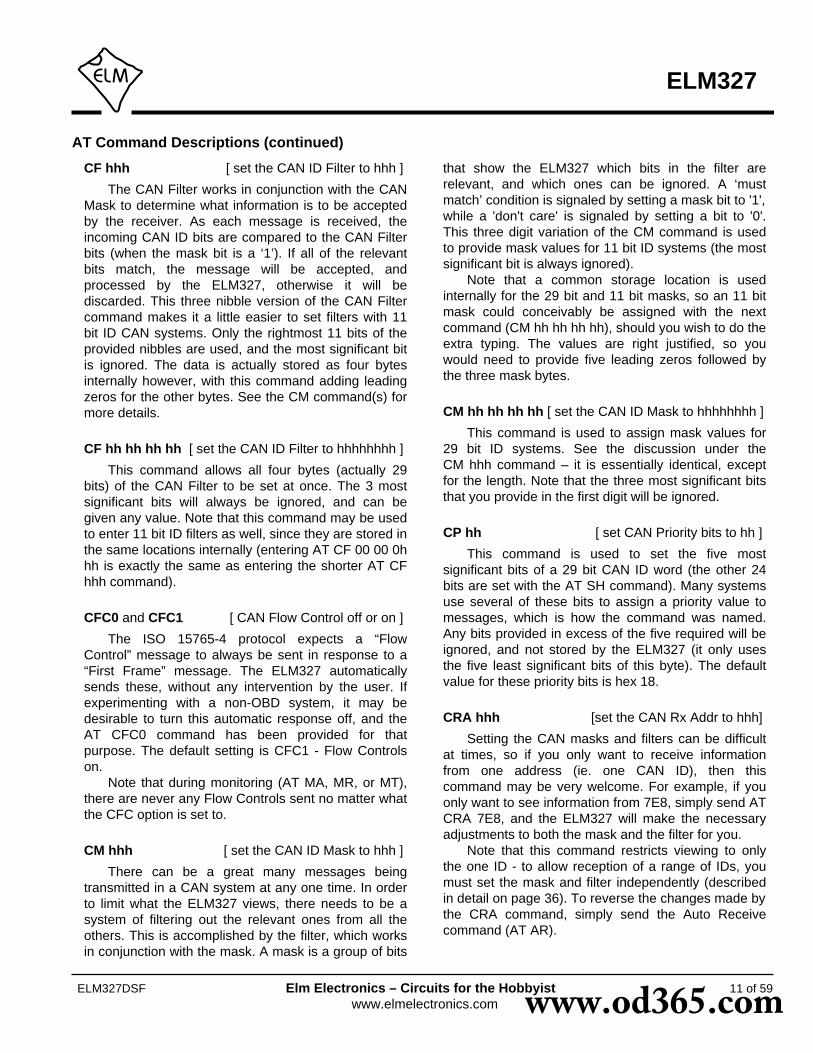
CF hhh [ set the CAN ID Filter to hhh ]
The CAN Filter works in conjunction with the CANMask to determine what information is to be acceptedby the receiver. As each message is received, theincoming CAN ID bits are compared to the CAN Filterbits (when the mask bit is a ‘1’). If all of the relevantbits match, the message will be accepted, andprocessed by the ELM327, otherwise it will bediscarded. This three nibble version of the CAN Filtercommand makes it a little easier to set filters with 11bit ID CAN systems. Only the rightmost 11 bits of theprovided nibbles are used, and the most significant bitis ignored. The data is actually stored as four bytesinternally however, with this command adding leadingzeros for the other bytes. See the CM command(s) formore details.
CF hh hh hh hh [ set the CAN ID Filter to hhhhhhhh ]
This command allows all four bytes (actually 29bits) of the CAN Filter to be set at once. The 3 mostsignificant bits will always be ignored, and can begiven any value. Note that this command may be usedto enter 11 bit ID filters as well, since they are stored inthe same locations internally (entering AT CF 00 00 0hhh is exactly the same as entering the shorter AT CFhhh command).
CFC0 and CFC1 [ CAN Flow Control off or on ]
The ISO 15765-4 protocol expects a “FlowControl” message to always be sent in response to a“First Frame” message. The ELM327 automaticallysends these, without any intervention by the user. Ifexperimenting with a non-OBD system, it may bedesirable to turn this automatic response off, and theAT CFC0 command has been provided for thatpurpose. The default setting is CFC1 - Flow Controlson.
Note that during monitoring (AT MA, MR, or MT),there are never any Flow Controls sent no matter whatthe CFC option is set to.
CM hhh [ set the CAN ID Mask to hhh ]
There can be a great many messages beingtransmitted in a CAN system at any one time. In orderto limit what the ELM327 views, there needs to be asystem of filtering out the relevant ones from all theothers. This is accomplished by the filter, which worksin conjunction with the mask. A mask is a group of bits
that show the ELM327 which bits in the filter arerelevant, and which ones can be ignored. A ‘mustmatch’ condition is signaled by setting a mask bit to '1',while a 'don't care' is signaled by setting a bit to '0'.This three digit variation of the CM command is usedto provide mask values for 11 bit ID systems (the mostsignificant bit is always ignored).
Note that a common storage location is usedinternally for the 29 bit and 11 bit masks, so an 11 bitmask could conceivably be assigned with the nextcommand (CM hh hh hh hh), should you wish to do theextra typing. The values are right justified, so youwould need to provide five leading zeros followed bythe three mask bytes.
CM hh hh hh hh [ set the CAN ID Mask to hhhhhhhh ]
This command is used to assign mask values for29 bit ID systems. See the discussion under theCM hhh command – it is essentially identical, exceptfor the length. Note that the three most significant bitsthat you provide in the first digit will be ignored.
CP hh [ set CAN Priority bits to hh ]
This command is used to set the five mostsignificant bits of a 29 bit CAN ID word (the other 24bits are set with the AT SH command). Many systemsuse several of these bits to assign a priority value tomessages, which is how the command was named.Any bits provided in excess of the five required will beignored, and not stored by the ELM327 (it only usesthe five least significant bits of this byte). The defaultvalue for these priority bits is hex 18.
CRA hhh [set the CAN Rx Addr to hhh]
Setting the CAN masks and filters can be difficultat times, so if you only want to receive informationfrom one address (ie. one CAN ID), then thiscommand may be very welcome. For example, if youonly want to see information from 7E8, simply send ATCRA 7E8, and the ELM327 will make the necessaryadjustments to both the mask and the filter for you.
Note that this command restricts viewing to onlythe one ID - to allow reception of a range of IDs, youmust set the mask and filter independently (describedin detail on page 36). To reverse the changes made bythe CRA command, simply send the Auto Receivecommand (AT AR).
AT Command Descriptions (continued)
www.od365.com

12 of 59
ELM327
ELM327DSF Elm Electronics – Circuits for the Hobbyistwww.elmelectronics.com
CRA hhhhhhhh [set the CAN Rx Addr to hhhhhhhh]
This command is identical to the previous one,except that it used to set 29 bit CAN IDs, instead of 11.The Auto Receive command (AT AR) is also used toreverse the changes made by this command.
CS [ show the CAN Status counts ]
The CAN protocol requires that statistics be keptregarding the number of transmit and receive errorsdetected. If there should be a significant number oferrors (due to a hardware or software problem), thedevice will go off-line in order to not affect other dataon the bus. The AT CS command lets you see boththe transmitter (Tx) and the receiver (Rx) error counts,in hexadecimal. If the transmitter should be off (count>FF), you will see ‘OFF’ rather than a specific count.
CV dddd [ Calibrate the Voltage to dd.dd volts ]
The voltage reading that the ELM327 shows for anAT RV request can be calibrated with this command.The argument (‘dddd’) must always be provided as 4digits, with no decimal point (it assumes that thedecimal place is between the second and the thirddigits).
To use this feature, simply use an accurate meterto read the actual input voltage, then use the CVcommand to change the internal calibration (scaling)factor. For example, if the ELM327 shows the voltageas 12.2V while you measure 11.99 volts, then sendAT CV 1199 and the ELM327 will recalibrate itself forthat voltage (it will actually read 12.0V due to digitroundoff). See page 22 for some more information onhow to read voltages and perform the calibration.
D [ set all to Defaults ]
This command is used to set the options to theirdefault (or factory) settings, as when power is firstapplied. The last stored protocol will be retrieved frommemory, and will become the current setting (possiblyclosing other protocols that are active). Any settingsthat the user had made for custom headers, filters, ormasks will be restored to their default values, and alltimer settings will also be restored to their defaults.
D0 and D1 [ display DLC off (0) or on (1) ]
Standard CAN (ISO 15765-4) OBD requires that allmessages have 8 data bytes, so displaying the
number of data bytes (the DLC) is not normally veryuseful. When experimenting with other protocols,however, it may be useful to be able to see what thedata lengths are. The D0 and D1 commands controlthe display of the DLC digit (the headers must also beon, in order to see this digit). When displayed, thesingle DLC digit will appear between the ID (header)bytes and the data bytes. The default setting isdetermined by PP 29.
DM1 [ monitor for DM1s ]
The SAE J1939 Protocol broadcasts trouble codesperiodically as they are detected, using DiagnosticMode 1 (DM1) messages. This command sets theELM327 to continually monitor for this type ofmessage for you, following multi-segment transportprotocols as required. Note that a combination ofmasks and filters could be set to provide a similaroutput, but they would not allow multiline messages tobe detected. The DM1 command adds the extra logicthat is needed for multiline messages.
This command is only available when a CANProtocol (A, B, or C) has been selected for J1939formatting. It returns an error if attempted under anyother conditions.
DP [ Describe the current Protocol ]
The ELM327 is capable of automaticallydetermining the appropriate OBD protocol to use foreach vehicle that it is connected to. When the ICconnects to a vehicle, however, it returns only the datarequested, and does not report the protocol found. TheDP command is used to display the current protocolthat the ELM327 is selected for (even if it is notconnected). If the automatic option is also selected,the protocol will show the word "AUTO" before it,followed by the type. Note that the actual protocolnames are displayed, not the numbers used by theprotocol setting commands.
DPN [ Describe the Protocol by Number ]
This command is similar to the DP command, butit returns a number which represents the currentprotocol. If the automatic search function is alsoenabled, the number will be preceded with the letter‘A’. The number is the same one that is used with theset protocol and test protocol commands.
AT Command Descriptions (continued)
www.od365.com
13 of 59
ELM327
ELM327DSF Elm Electronics – Circuits for the Hobbyistwww.elmelectronics.com
E0 and E1 [ Echo off (0) or on (1) ]
These commands control whether or not thecharacters received on the RS232 port are echoed(retransmitted) back to the host computer. Characterecho can be used to confirm that the characters sentto the ELM327 were received correctly. The default isE1 (or echo on).
FC SM h [ Flow Control Set Mode to h ]
This command sets how the ELM327 responds toFirst Frame messages when automatic Flow Controlresponses are enabled. The single digit provided caneither be ‘0’ (the default) for fully automatic responses,‘1’ for completely user defined responses, or ‘2’ foruser defined data bytes in the response. Morecomplete details and examples can be found in theAltering Flow Control Messages section (page 40).
FC SH hhh [ Flow Control Set Header to… ]
The header (or more properly ‘CAN ID’) bytesused for CAN Flow Control response messages canbe set using this command. Only the right-most 11 bitsof those provided will be used - the most significant bitis always removed. This command only affects FlowControl mode 1.
FC SH hhhhhhhh [ Flow Control Set Header to… ]
This command is used to set the header (or ‘CANID’) bits for Flow Control responses with 29 bit CAN IDsystems. Since the 8 nibbles define 32 bits, only theright-most 29 bits of those provided will be used - themost significant three bits are always removed. Thiscommand only affects Flow Control mode 1.
FC SD [1-5 bytes] [ Flow Control Set Data to… ]
The data bytes that are sent in a CAN FlowControl message can be set with this command. Thecurrent version of the software allows one to five databytes to be defined, with the remainder of the databytes in the message being automatically set to thedefault CAN filler byte. Data provided with thiscommand is only used when Flow Control modes 1 or2 have been enabled.
FE [ Forget Events ]
There are certain events which may change howthe ELM327 responds from that point on. One of these
is the occurance of an ERR94 condition, that blockssubsequent searching through CAN protocols if PP 2Abit 5 is ‘1’. Normally, an event such as this will affect allsearches until the next power off and on, but it can be‘forgotten’ using software, with the AT FE command.Similarly, an ‘LV RESET’ event will prevent searchesthrough CAN protocols if PP 2A bit 4 is ‘1’, and it mayalso be forgotten with the FE command. FE is a newcommand with v1.3a of the IC.
H0 and H1 [ Headers off (0) or on (1) ]
These commands control whether or not theadditional (header) bytes of information are shown inthe responses from the vehicle. These are normallynot shown by the ELM327, but can be turned on byissuing the AT H1 command.
Turning the headers on actually shows more thanjust the header bytes – you will see the completemessage as transmitted, including the check-digits andPCI bytes, and possibly the CAN data length code(DLC) if it has been enabled with PP 29. The currentversion of this IC does not display the CAN CRC code,nor the special J1850 IFR bytes (which some protocolsuse to acknowledge receipt of a message).
I [ Identify yourself ]
Issuing this command causes the chip to identifyitself, by printing the startup product ID string (currently“ELM327 v1.3a”). Software can use this to determineexactly which integrated circuit it is talking to, withouthaving to reset the IC.
IB 10 [ set the ISO Baud rate to 10400 ]
This command restores the ISO 9141-2 andISO 14230-4 baud rates to the default value of 10400.
IB 96 [ set the ISO Baud rate to 9600 ]
Several users have requested this command. It isused to change the baud rate used for the ISO 9141-2and ISO 14230-4 protocols (numbers 3, 4, and 5) to9600 baud, while relaxing some of the requirementsfor the initiation byte transfers. It may be useful forexperimenting with some vehicles. Normal 10,400baud operation can be restored at any time by issuingan IB 10 command.
AT Command Descriptions (continued)
www.od365.com

IFR0, IFR1, and IFR2 [ IFR control ]
The SAE J1850 protocol allows for an In-FrameResponse (IFR) byte to be sent after each message,usually to acknowledge the correct receipt of thatmessage. The ELM327 automatically generates andsends this byte for you by default, but you can overridethis behaviour with this command.
The AT IFR0 command will disable the sending ofall IFRs, no matter what the header bytes require.AT IFR2 is the opposite - it will force an IFR byte toalways be sent, no matter what header bytes indicate.The AT IFR1 command restores the response toprovide the automatic sending of IFRs, as determinedby the ‘K’ bit of the header byte. IFR1 is the defaultsetting of the ELM327.
IFR H and IFR S [ IFR from Header or Source ]
The value sent in the J1850 In-Frame Response(IFR) byte is normally the same as the value sent asthe Source (or Tester) Address byte that was in theheader of the request. There may be occasions whenit is desireable to use some other value, however, andthis set of commands allows for this.
If you send AT IFR S, the ELM327 will use thevalue defined as the Source Address (usually F1, but itcan be changed with PP 06), even if another valuewas sent in the Header bytes. This is not what isnormally required, and caution should be used whenusing AT IFR S. AT IFR H restores the sending of theIFR bytes to those provided in the Header, and is thedefault setting.
IIA hh [ set the ISO Init Address to hh ]
The ISO 9141-2 and ISO 14230-4 standards statethat when beginning a session with an ECU, theinitiation sequence is to be directed to a specificaddress ($33). If you wish to experiment by directingthe slow five baud sequence to another address, it isdone with this command. For example, if you preferthat the initiation be performed with the ECU ataddress $7A, then simply send:
>AT IIA 7A
and the ELM327 will use that address when called todo so (protocols 3 or 4). The full eight bit value is usedexactly as provided – no changes are made to it (ie noadding of parity bits, etc.)
Note that setting this value does not affect any
address values used in the header bytes. The ISO initaddress is restored to $33 whenever the defaults, orthe ELM327, are reset.
JE [ enables the J1939 ELM data format ]
The J1939 standard requires that PGN requestsbe sent with the byte order reversed from the standard‘left-to-right’ order, which many of us would expect. Forexample, to send a request for the engine temperature(PGN 00FEEE), the data bytes are actually sent in thereverse order (ie EE FE 00), and the ELM327 wouldnormally expect to receive the data in that order forpassing on to the vehicle.
When experimenting, this constant need for bytereversals can be quite confusing, so we have definedan ELM format that reverses the bytes for you. Whenthe J1939 ELM (JE) format is enabled, and you have aJ1939 protocol selected, and you provide three databytes to the ELM327, it will reverse the order for youbefore sending them to the ECU. To request theengine temperature PGN, you would send 00 FE EE(and not EE FE 00). The ‘JE’ type of automaticformatting is enabled by default.
JS [ enables the J1939 SAE data format ]
The AT JS command disables the automatic bytereordering that the JE command performs for you. Ifyou wish to send data bytes to the J1939 vehiclewithout any manipulation of the byte order, then selectJS formatting.
Using the above example for engine temperature(PGN 00FEEE) with the data format set to JS, youmust send the bytes to the ELM327 as EE FE 00 (thisis also known as little-endian byte ordering).
The JS type of data formatting is off by default, butwas the only type of data formatting provided by theELM327 v1.2. If you are switching from version 1.2 ofthe IC, take note of this difference.
KW [ display the Key Words ]
When the ISO 9141-2 and ISO 14230-4 protocolsare initialized, two special bytes (key words) arepassed to the ELM327 (the values are used internallyto determine whether a particular protocol variationcan be supported by the ELM327). If you wish to seewhat the value of these bytes were, simply send theAT KW command.
14 of 59
ELM327
ELM327DSF Elm Electronics – Circuits for the Hobbyistwww.elmelectronics.com
AT Command Descriptions (continued)
www.od365.com

15 of 59
ELM327
ELM327DSF Elm Electronics – Circuits for the Hobbyistwww.elmelectronics.com
KW0 and KW1 [ Key Word checks off (0) or on (1) ]
The ELM327 looks for specific bytes (called KeyWords) to be sent to it during the ISO 9141-2 andISO14230-4 initiation sequences. If those bytes arenot found, the initiation is said to have failed (youmight see “UNABLE TO CONNECT” or perhaps “BUSINIT: ...ERROR”). This may be because you are tryingto connect to a non-OBD compliant ECU, or perhapsto an older one.
If you wish to experiment, but do not want theELM327 to check the values contained in the keywords, you can turn the checking off with:
>AT KW0
after which the IC will look for Key Word bytes in theresponse, but will not look at the actual values of thebytes. This may allow a connection in an otherwise‘impossible’ situation. Normal behaviour can bereturned with AT KW1, which is the default setting.
Caution should be used with this command, asyou are bypassing the checks that are normallyperformed on the keyword bytes. The ELM327 sendsan acknowledgement to the ECU for these bytes, butthat is without considering what the bytes actually are.You could be incorrectly activating an ISO 9141, orKWP 2000 protocol, so should be very careful.
L0 and L1 [ Linefeeds off (0) or on (1) ]
This option controls the sending of linefeedcharacters after each carriage return character. ForAT L1, linefeeds will be generated after every carriagereturn character, and for AT L0, they will be off. Userswill generally wish to have this option on if using aterminal program, but off if using a custom computerinterface (as the extra characters transmitted will onlyserve to slow the communications down). The defaultsetting is determined by the voltage at pin 7 duringpower on (or reset). If the level is high, then linefeedson will be the default; otherwise it will be linefeeds off.
M0 and M1 [ Memory off (0) or on (1) ]
The ELM327 has internal ‘non-volatile’ memorythat is capable of remembering the last protocol used,even after the power is turned off. This can beconvenient if the IC is often used for one particularprotocol, as that will be the first one attempted whennext powered on. To enable this memory function, it isnecessary to either use an AT command to select theM1 option, or to have chosen “memory on” as the
default power on mode (by connecting pin 5 of theELM327 to a high logic level).
When the memory function is enabled, each timethat the ELM327 finds a valid OBD protocol, thatprotocol will be memorized (stored) and will becomethe new default. If the memory function is not enabled,protocols found during a session will not bememorized, and the ELM327 will always start at powerup using the same (last saved) protocol.
If the ELM327 is to be used in an environmentwhere the protocol is constantly changing, it wouldlikely be best to turn the memory function off, andissue an AT SP 0 command once. The SP 0 commandtells the ELM327 to start in an 'Automatic' protocolsearch mode, which is the most useful for an unknownenvironment. ICs come from the factory set to thismode. If, however, you have only one vehicle that youregularly connect to, storing that vehicle’s protocol asthe default would make the most sense.
As mentioned, the default setting for the memoryfunction is determined by the voltage level at pin 5 atpower up (or system reset). If it is connected to a highlevel (VDD), then the memory function will be on bydefault. If pin 5 is connected to a low level, thememory saving will be off by default.
MA [ Monitor All messages ]
This command places the ELM327 into a busmonitoring mode, in which it continually monitors for(and displays) all messages that it sees on the OBDbus. It is a quiet monitor, not sending In FrameResponses for J1850 systems, Acknowledges for CANsystems, or Wakeup (‘keep-alive’) messages for theISO 9141 and ISO 14230 protocols. Monitoring willcontinue until it is stopped by activity on the RS232input, or the RTS pin.
To stop the monitoring, simply send any singlecharacter to the ELM327, then wait for it to respondwith a prompt character (‘>’), or a low level output onthe Busy pin. (Setting the RTS input to a low level willinterrupt the device as well.) Waiting for the prompt isnecessary as the response time varies depending onwhat the IC was doing when it was interrupted. If forinstance it is in the middle of printing a line, it will firstcomplete that line then return to the command state,issuing the prompt character. If it were simply waitingfor input, it would return immediately. Note that thecharacter which stops the monitoring will always bediscarded, and will not affect subsequent commands.
Beginning with v1.3 of this IC, all messages will be
AT Command Descriptions (continued)
www.od365.com

16 of 59
ELM327
ELM327DSF Elm Electronics – Circuits for the Hobbyistwww.elmelectronics.com
AT Command Descriptions (continued)
printed as found, even if the CAN auto formatting is on(CAF1). The previous version of this IC (v1.2) did notdisplay some illegal CAN messages if the automaticformatting was on, but now all messages received aredisplayed, and if the data format does not appear to becorrect, then “<DATA ERROR” will be shown besidethe data.
If this command is used with CAN protocols, and ifthe CAN filter and/or mask were previously set (withCF, CM or CRA), then the MA command will beaffected by the settings. For example, if the receiveaddress had been set previously with CRA 4B0, thenthe AT MA command would only be able to ‘see’messages with an ID of 4B0. This is often not what isdesired - you may want to reset the masks and filters(with AT AR) first.
All of the monitoring commands (MA, MR and MT)operate by closing the current protocol (an AT PC isexecuted internally), then configuring the IC for silentmonitoring of the data (no wakeup messages, IFRs orCAN acknowledges are sent by the ELM327). Whenthe next OBD command is to be transmitted, theprotocol will again be initialized, and you may seemessages stating this. “SEARCHING...” may also beseen, depending on what changes were made whilemonitoring.
MP hhhh [ Monitor for PGN hhhh ]
The AT MA, MR and MT commands are quiteuseful for when you wish to monitor for a specific bytein the header of a typical OBD message. For the SAEJ1939 Protocol, however, it is often desireable tomonitor for the multi-byte Parameter Group Numbers(or PGNs), which can appear in either the header, orthe data bytes. The MP command is a special J1939only command that is used to look for responses to aparticular PGN request, and follow any multi-segmentoccurances of them.
Note that this MP command provides no means toset the first two digits of the requested PGN, and theyare always assumed to be 00. For example, the DM2PGN has an assigned value of 00FECB (see SAEJ1939-73). To monitor for DM2 messages, you wouldissue AT MP FECB, eliminating the 00, since theMP hhhh command always assumes that the PGN ispreceeded by two zeros.
This command is only available when a CANProtocol (A, B, or C) has been selected for SAE J1939formatting. It returns an error if attempted under anyother conditions. Note also that this version of the
ELM327 only displays responses that match thecriteria, not the requests that are asking for theinformation.
MP hhhhhh [ Monitor for PGN hhhhhh ]
This command is very similar to the MP hhhhcommand, but it extends the number of bytes providedby one, so that there is complete control over the PGNdefinition (it does not make the assumption that theData Page bit is 0, as the MP hhhh command does).This allows for future expansion, should additionalPGNs be defined with the Data Page bit set. Note thatonly the Data Page bit is relevant in the extra byte -the Reserved and Priority bits are ignored.
MR hh [ Monitor for Receiver hh ]
This command is very similar to the AT MAcommand except that it will only display messages thatwere sent to the hex address given by hh. These aremessages which are found to have the value hh in thesecond byte of a traditional three byte OBD header, inbits 8 to 15 of a 29 bit CAN ID, or in bits 8 to 10 of an11 bit CAN ID. Any single RS232 character aborts themonitoring, as with the MA command.
Note that if this command is used with CANprotocols, and if the CAN filter and/or mask werepreviously set (with CF, CM or CRA), then the MRcommand will over-write the previous values for thesebits only - the others will remain unchanged. As anexample, if the receive address has been set withCRA 4B0, and then you send MR 02, the 02 willreplace the 4, and the CAN masks/filters will only allowIDs that are equal to 2B0. This is often not what isdesired - you may want to reset the masks and filters(with AT AR) first.
As with the AT MA command, this commandbegins by performing an internal Protocol Close.Subsequent OBD requests may show “SEARCHING”or “BUS INIT”, etc. messages when the protocol isreactivated.
MT hh [ Monitor for Transmitter hh ]
This command is also very similar to the AT MAcommand, except that it will only display messagesthat were sent by the transmitter with the hex addressgiven by hh. These are messages which are found tohave that value in the third byte of a traditional threebyte OBD header, or in bits 0 to 7 for CAN IDs. As with
www.od365.com

17 of 59
ELM327
ELM327DSF Elm Electronics – Circuits for the Hobbyistwww.elmelectronics.com
AT Command Descriptions (continued)
the MA and MR monitoring modes, any RS232 activity(single character) aborts the monitoring.
Note that if this command is used with CANprotocols, and if the CAN filter and/or mask werepreviously set (with CF, CM or CRA), then the MTcommand will over-write the previous values for thesebits only - the others will remain unchanged. As anexample, if the receive address has been set withCRA 4B0, and then you send MT 20, the 20 willreplace the B0, and the CAN masks/filters will onlyallow IDs that are equal to 420. This is often not whatis desired - you may want to reset the masks andfilters (with AT AR) first.
As with the AT MA command, this commandbegins by performing an internal Protocol Close.Subsequent OBD requests may show “SEARCHING”or “BUS INIT”, etc. messages when the protocol isreactivated.
NL [ Normal Length messages ]
Setting the NL mode on forces all sends andreceives to be limited to the standard seven data bytesin length, similar to the other ELM32x OBD ICs. Toallow longer messages, use the AL command.
Beginning with v1.2, the ELM327 does not requirea change to AL to allow longer message lengths forthe KWP protocols to be received (as determined bythe header length values). You can simply leave the ICset to the default setting of NL, and all of the receivedbytes will be shown.
PC [ Protocol Close ]
There may be occasions where it is desirable tostop (deactivate) a protocol. Perhaps you are not usingthe automatic protocol finding, and wish to manuallyactivate and deactivate protocols. Perhaps you wish tostop the sending of idle (wakeup) messages, or haveanother reason. The PC command is used in thesecases to force a protocol to close.
PP hh OFF [ turn Prog. Parameter hh OFF ]
This command disables Programmable Parameternumber hh. Any value assigned using the PP hh SVcommand will no longer be used, and the factorydefault setting will once again be in effect. The actualtime when the new value for this parameter becomeseffective is determined by its type. Refer to theProgrammable Parameters section (page 45) for more
information on the types.Note that ‘PP FF OFF’ is a special command that
disables all of the Programmable Parameters, as if youhad entered PP OFF for every possible one.
It is possible to alter some of the ProgrammableParameters so that it may be difficult, or evenimpossible, to communicate with the ELM327. If thisoccurs, there is a hardware means of resetting all ofthe Programmable Parameters at once. Connect ajumper from circuit common to pin 28, holding it therewhile powering up the ELM327 circuit. Hold it inposition until you see the RS232 Receive LED begin toflash (which indicates that all of the PPs have beenturned off). At this point, remove the jumper to allowthe IC to perform a normal startup. Note that a reset ofthe PPs occurs quite quickly – if you are holding thejumper on for more than a few seconds and do not seethe RS232 receive light flashing, remove the jumperand try again – there may be a problem with yourconnection. This feature is only available beginningwith v1.2, and is not a provided with any earlierversions of the ELM327 IC.
PP hh ON [ turn Programmable Parameter hh ON ]
This command enables Programmable Parameternumber hh. Once enabled, any value assigned usingthe PP hh SV command will be used where the factorydefault value was before. (All of the programmableparameter values are set to their default values at thefactory, so enabling a programmable parameter beforeassigning a value to it will not cause problems.) Theactual time when the value for this parameter becomeseffective is determined by its type. Refer to theProgrammable Parameters section (page 45) for moreinformation on the types.
Note that ‘PP FF ON’ is a special command thatenables all of the Programmable Parameters at thesame time.
PP xx SV yy [ Prog. Param. xx: Set the Value to yy ]
A value is assigned to a Programmable Parameterusing this command. The system will not be able touse this new value until the Programmable Parameterhas been enabled, however.
PPS [ Programmable Parameter Summary ]
The complete range of current ProgrammableParameters are displayed with this command (even
www.od365.com

18 of 59
ELM327
ELM327DSF Elm Electronics – Circuits for the Hobbyistwww.elmelectronics.com
AT Command Descriptions (continued)
those not yet implemented). Each is shown as a PPnumber followed by a colon and the value that isassigned to it. This is followed by a single digit – either‘N’ or ‘F’ to show that it is ON (enabled), or OFF(disabled), respectively. See the ProgrammableParameters section for a more complete discussion.
R0 and R1 [ Responses off (0) or on (1) ]
These commands control the ELM327’s automaticreceive (and display) of the messages returned by thevehicle. If responses have been turned off, the IC willnot wait for a reply from the vehicle after sending arequest, and will return immediately to wait for the nextRS232 command (the ELM327 does not print anythingto say that the send was successful, but you will see amessage if it was not).
R0 may be useful to send commands blindly whenusing the IC for a non-OBD network application, orwhen simulating an ECU in a learning environment. Itis not recommended that this option normally be used,however, as the vehicle may have difficulty if it isexpecting an acknowledgement byte and neverreceives one.
An R0 setting will always override any number ofresponses digit that is provided with an OBD request.The default setting is R1, or responses on.
RA hh [ set the Receive Address to hh ]
Depending on the application, users may wish tomanually set the address to which the ELM327 willrespond. Issuing this command will turn off the ARmode, and force the IC to only accept responsesaddressed to hh. Use caution with this setting, asdepending on what you set it to, you may end upaccepting (acknowledging with an IFR) a message thatwas actually meant for another module. To turn off theRA filtering, simply send AT AR.
This command is not very effective for use with theCAN protocols, as it only monitors for one portion ofthe ID bits, and that is not likely enough for most CANapplications - the CRA command may be a betterchoice. Also, this command has no effect on theaddresses used by the J1939 protocols, as the J1939routines derive them from the header values, asrequired by the SAE standard.
This RA command is exactly the same as the SRcommand, and can be used interchangeably with it.
RTR [ send an RTR message ]
This command causes a special “Remote Frame”CAN message to be sent. This type of message hasno data bytes, and has its Remote TransmissionRequest (RTR) bit set. The headers and filters willremain as previously set (ie the ELM327 does notmake any assumptions as to what format a responsemay have), so adjustments may need to be made tothe mask and filter. This command must be used withan active CAN protocol, and will return an error if theprotocol is not. Note that the CAF1 setting normallyeliminates the display of all RTRs, so if you aremonitoring messages and want to see the RTRs, youwill have to turn off formatting, or turn the headers on.
The ELM327 treats an RTR just like any othermessage send, and will wait for a response from thevehicle (unless AT R0 has been chosen).
RV [ Read the input Voltage ]
This initiaties the reading of the voltage present atpin 2, and the conversion of it to a decimal voltage. Bydefault, it is assumed that the input is connected to thevoltage to be measured through a 47KΩ and 10KΩresistor divider (with the 10KΩ connected from pin 2 toVss), and that the ELM327 supply is a nominal 5V.This will allow for the measurement of input voltagesup to about 28V, with an uncalibrated accuracy oftypically about 2%.
S0 and S1 [ printing of Spaces off (0) or on (1) ]
These commands control whether or not spacecharacters are inserted in the ECU response.
The ELM327 normally reports ECU responses asa series of hex characters that are separated by spacecharacters (to improve readability), but messages canbe transferred much more quickly if every third byte(the space) is removed. While this makes the messageless readable for humans, it can provide significantimprovements for computer processing of the data. Bydefault, spaces are on (S1), and space characters areinserted in every response.
SH xyz [ Set the Header to 00 0x yz ]
Entering CAN 11 bit ID words (headers) normallyrequires that extra leading zeros be added (eg. AT SH00 07 DF), but this command simplifies doing so. TheAT SH xyz command accepts a three digit argument,takes only the right-most 11 bits from that, adds
www.od365.com

19 of 59
ELM327
ELM327DSF Elm Electronics – Circuits for the Hobbyistwww.elmelectronics.com
AT Command Descriptions (continued)
leading zeros, and stores the result in the headerstorage locations for you. As an example, AT SH 7DFis a valid command, and is quite useful for workingwith 11 bit CAN systems. It actually results in theheader bytes being internally stored as 00 07 DF.
SH xx yy zz [ Set the Header to xx yy zz ]
This command allows the user to manually controlthe values that are sent as the three header bytes in amessage. These bytes are normally assigned valuesfor you (and are not required to be adjusted), but theremay be occasions when it is desirable to change them(particularly if experimenting with physical addressing).
The header bytes are defined with hexadecimaldigits - xx will be used for the first or priority/type byte,yy will be used for the second or receiver/target byte,and zz will be used for the third or transmitter/sourcebyte. These remain in effect until set again, or untilrestored to their default values with the D, WS, or Zcommands.
If new values for header bytes are set before thevehicle protocol has been determined, and if thesearch is not set for fully automatic (ie other thanprotocol 0), these new values will be used for theheader bytes of the first request to the vehicle. If thatfirst request should fail to obtain a response, and if theautomatic search is enabled, the ELM327 will thencontinue to search for a protocol using default valuesfor the header bytes. Once a valid protocol is found,the header bytes will revert to the values assigned withthe AT SH command.
This command is used to assign all header bytes,whether they are for a J1850, ISO 9141, ISO 14230, ora CAN system. The CAN systems will use these threebytes to fill bits 0 to 23 of the ID word (for a 29 bit ID),or will use only the rightmost 11 bits for an 11 bit CANID (and any extra bits assigned will be ignored). Theadditional 5 bits needed for a 29 bit system are setwith the AT CP command.
If assigning header values for the KWP protocols(4 and 5), care must be taken when setting the firstheader byte (xx) value. The ELM327 will always insertthe number of data bytes for you, but how it is donedepends on the values that you assign to this byte. Ifthe second digit of this first header byte is anythingother than 0 (zero), the ELM327 assumes that youwish to have the length value inserted in that first bytewhen sending. In other words, providing a length valuein the first header byte tells the ELM327 that you wishto use a traditional 3 byte header, where the length is
stored in the first byte of the header.If you provide a value of 0 for the second digit of
the first header byte, the ELM327 will assume that youwish that value to remain as 0, and that you want tohave a fourth header (length) byte inserted into themessage. This is contrary to the ISO 14230-4 OBDstandard, but it is in use by many KWP2000 systemsfor (non-OBD) data transfer, so may be useful whenexperimenting. Support for 4 byte KWP headers wasadded with v1.2 of the ELM327 IC, and is not availablein previous versions.
SP h [ Set Protocol to h ]
This command is used to set the ELM327 foroperation using the protocol specified by 'h', and toalso save it as the new default. Note that the protocolwill be saved no matter what the AT M0/M1 setting is.
The currently valid protocols are:
0 - Automatic1 - SAE J1850 PWM (41.6 Kbaud)2 - SAE J1850 VPW (10.4 Kbaud)3 - ISO 9141-2 (5 baud init, 10.4 Kbaud)4 - ISO 14230-4 KWP (5 baud init, 10.4 Kbaud)5 - ISO 14230-4 KWP (fast init, 10.4 Kbaud)6 - ISO 15765-4 CAN (11 bit ID, 500 Kbaud)7 - ISO 15765-4 CAN (29 bit ID, 500 Kbaud)8 - ISO 15765-4 CAN (11 bit ID, 250 Kbaud)9 - ISO 15765-4 CAN (29 bit ID, 250 Kbaud)A - SAE J1939 CAN (29 bit ID, 250* Kbaud)B - USER1 CAN (11* bit ID, 125* Kbaud)C - USER2 CAN (11* bit ID, 50* Kbaud)
* default settings (user adjustable)
The first protocol shown (0) is a convenient way oftelling the ELM327 that the vehicle’s protocol is notknown, and that it should perform a search. It causesthe ELM327 to try all protocols if necessary, looking forone that can be initiated correctly. When a validprotocol is found, and the memory function is enabled,that protocol will then be remembered, and willbecome the new default setting. When saved like this,the automatic mode searching will still be enabled, andthe next time the ELM327 fails to connect to the savedprotocol, it will again search all protocols for anothervalid one. Note that some vehicles respond to morethan one protocol - during a search, you may see morethan one type of response.
www.od365.com

20 of 59
ELM327
ELM327DSF Elm Electronics – Circuits for the Hobbyistwww.elmelectronics.com
AT Command Descriptions (continued)
ELM327 users often use the AT SP 0 command toreset the search protocol before starting (or restarting)a connection. This works well, but as with any SetProtocol command, it involves a write to EEPROM,and an unnecessary delay (of about 30 msec) whilethe write occurs. Beginning with v1.3 of the ELM327, awrite to EEPROM will no longer be performed for anSP 0 (or an SP A0, or SP 0A) command, but it will stillreset the protocol to 0 for you. If you really want tochange what is stored in the internal EEPROM, youmust now use the new AT SP 00 command.
If another protocol (other than 0) is selected withthis command (eg. AT SP 3), that protocol will becomethe default, and will be the only protocol used by theELM327. Failure to initiate a connection in thissituation will result in familiar responses such as ‘BUSINIT: ...ERROR’, and no other protocols will beattempted. This is a useful setting if you know thatyour vehicle(s) only require the one protocol.
SP Ah [ Set Protocol to Auto, h ]
This variation of the SP command allows you tochoose a starting (default) protocol, while still retainingthe ability to automatically search for a valid protocolon a failure to connect. For example, if your vehicle isISO 9141-2, but you want to occasionally use theELM327 circuit on other vehicles, you might use theAT SP A3 command, so that the first protocol tried willthen be yours (3), but it will also automatically searchfor other protocols. Don't forget to disable the memoryfunction if doing this, or your neighbour’s protocolcould become your new default.
As for SP h, an SP Ah will save the protocolinformation even if the memory option is off (except forSP A0 and SP 0A which as of v1.3 no longer cause awrite - if you need to, use SP 00). Note that the ‘A’ cancome before or after the h, so AT SP A3 can also beentered as AT SP 3A.
SR hh [Set the Receive address to hh ]
Depending on the application, users may wish tomanually set the address to which the ELM327 willrespond. Issuing this command will turn off the ARmode, and force the IC to only accept responsesaddressed to hh. Use caution with this setting, asdepending on what you set it to, you may end upaccepting (acknowledging with an IFR) a message thatwas actually meant for another module. To turn off theSR filtering, simply send AT AR.
This command is not very effective for use with theCAN protocols, as it only monitors for one portion ofthe ID bits, and that is not likely enough for most CANapplications - the CRA command may be a betterchoice. Also, this command has no effect on theaddresses used by the J1939 protocols, as the J1939routines derive them from the header values, asrequired by the SAE standard.
This SR command is exactly the same as the RAcommand, and can be used interchangeably with it.
ST hh [ Set Timeout to hh ]
After sending a request, the ELM327 waits apreset time for a response before it can declare thatthere was ‘NO DATA’ received from the vehicle. Thesame timer setting is also used after a response hasbeen received, while waiting to see if more arecoming. The AT ST command allows this timer to beadjusted, in increments of 4 msec.
When Adaptive Timing is enabled, the AT ST timesets the maximum time that is to be allowed, even ifthe adaptive algorithm determines that the settingshould be higher. In most circumstances, it is best toleave the AT ST time at the default setting when usingadaptive timing.
The ST timer is set to 32 by default (giving a timeof approximately 200 msec), but this value can beadjusted by changing PP 03. Note that a value of 00does not result in a time of 0 msec – it will restore thetimer to the default value.
SW hh [ Set Wakeup to hh ]
Once a data connection has been made, somevehicles require that there be data flow every fewseconds, or the connection may time out and ‘go tosleep.’ The ELM327 will automatically generateperiodic ‘wakeup’ messages in order to maintain thisconnection, whenever the user is not requesting anydata. (Currently, only protocols 3, 4, and 5 generatethese messages.) The replies to these messages arealways ignored, and are not visible to the user.
The time interval between these periodic ‘wakeup’messages can be adjusted in 20 msec incrementsusing the AT SW hh command, where hh is anyhexadecimal value from 00 to FF. The maximumpossible time delay of just over 5 seconds thus occurswhen a value of FF (decimal 255) is used. The defaultsetting provides a nominal delay of 3 seconds betweenmessages.
www.od365.com

21 of 59
ELM327
ELM327DSF Elm Electronics – Circuits for the Hobbyistwww.elmelectronics.com
Note that the value 00 (zero) is treated as a veryspecial case, and must be used with caution, as it willstop all periodic messages. This is provided as it maybe convenient in certain circumstances. IssuingAT SW 00 will not change a prior setting for the timebetween wakeup messages, should the protocol be re-initialized.
TP h [ Try Protocol h ]
This command is identical to the SP command,except that the protocol that you select is notimmediately saved in internal memory, so does notchange the default setting. Note that if the memoryfunction is enabled (AT M1), and this new protocol thatyou are trying is found to be valid, that protocol willthen be stored in memory as the new default.
TP Ah [ Try Protocol h with Auto ]
This command is very similar to the AT TPcommand above, except that if the protocol that is triedshould fail to initialize, the ELM327 will thenautomatically sequence through all of the protocols,attempting to connect to one of them.
V0 and V1 [ Variable data lengths off (0) or on (1) ]
These commands modify the current CAN protocolsettings to allow the sending of variable data lengthmessages, just as bit 6 of PP 2C and PP 2E do forprotocols B and C. This allows experimenting withvariable data length messages for any of the CANprotocols (not just B and C). The V1 command willalways override any protocol setting, and force avariable data length message. The default setting isV0, providing data lengths as determined by theprotocol.
WM [1 to 6 bytes] [ set Wakeup Message to… ]
This command allows the user to override thedefault settings for the wakeup messages (sometimesknown as the ‘periodic idle’ messages). Simply providethe bytes that you wish to have sent (one to six ofthem), and the ELM327 will then send them asrequired, at the rate determined by the AT SW setting.Note that you do not have to add a checksum byte tothe data – the ELM327 calculates the value and addsit for you.
WS [ Warm Start ]
This command causes the ELM327 to perform acomplete reset which is very similar to the AT Zcommand, but does not include the power on LEDtest. Users may find this a convenient means toquickly ‘start over’ without having the extra delay of theAT Z command.
If using variable RS232 baud rates (ie AT BRDcommands), it is preferred that you reset the IC usingthis command rather than AT Z, as AT WS will notaffect the chosen RS232 baud rate.
Z [ reset all ]
This command causes the chip to perform acomplete reset as if power were cycled off and then onagain. All settings are returned to their default values,and the chip will be put in the idle state, waiting forcharacters on the RS232 bus. Any baud rate that wasset with the AT BRD command will be lost, and theELM327 will return to the default baud rate setting.
@1 [ display the device description ]
This command causes the internal devicedescription string to be printed. The default text is“OBDII to RS232 Interpreter”.
@2 [ display the device identifier ]
The device identifier that was recorded with the@3 command is displayed with an AT @2 command.All 12 characters and a terminating carriage return willbe sent in response, if they have been defined. If noidentifier has been set, the @2 command returns anerror response (‘?’). The identifier may be useful forstoring product codes, production dates, serialnumbers, or other such codes.
@3 cccccccccccc [ store the device identifier ]
This command is used to set the device identifiercode. Exactly 12 characters must be sent, and oncewritten to memory, they can not be changed (ie it is‘write once, read many’). The characters sent must beprintable (ascii character values 00x21 to 0x5Finclusive).
AT Command Descriptions (continued)
www.od365.com
22 of 59
ELM327
ELM327DSF Elm Electronics – Circuits for the Hobbyistwww.elmelectronics.com
Reading the Battery Voltage
Before proceding to the OBD Commands, we willshow an example of how to use an AT Command. Wewill assume that you have built (or purchased) a circuitwhich is similar to that of Figure 9 in the ExampleApplications section (page 56). This circuit provides aconnection to read the vehicle’s battery voltage, whichmany will find very useful.
If you look in the AT Command list, you will seethere is one command that is listed as RV [Read theinput Voltage]. This is the command which you willneed to use. First, be sure that the prompt character isshown (that is the ‘>’ character), then simply enter ‘AT’followed by RV, and press return (or enter):
>AT RV
Note that we used upper case characters for thisrequest, but it was not required, as the ELM327 willaccept upper case (AT RV) as well as lower case(at rv) or any combination of these (At rV). It does notmatter if you insert space characters (‘ ’) between the‘AT’ and the ‘RV’ either, as they will be ignored by theELM327.
A typical reposnse to this command will show avoltage reading, followed by another prompt character:
12.6V
>
The accuracy of this reading depends on severalfactors. As shipped from the factory, the ELM327voltage reading circuitry will typically be accurate toabout 2%. For many, this is all that is needed. Somepeople may want to calibrate the circuitry for moreaccurate readings, however, so we have provided aspecial ‘Calibrate Voltage’ command for this.
To change the internal calibration constants, youwill need to know the actual battery voltage to moreaccuracy than the ELM327 shows. Many quality digitalmultimeters can do this, but you should verify theaccuracy before making a change.
For this example, let us assume that you haveconnected your multimeter, and you find that it reads12.47V. The ELM327 is a little high at 12.6V, and youwould like the ELM327 to read the same as yourmeter. Simply calibrate the ELM327 to that voltageusing the CV command:
>AT CV 1247OK
Note that you should not provide a decimal point inthe CV value, as the ELM327 knows that it should bebetween the second and the third digits.
At this point, the internal calibration values havebeen changed (ie. written to EEPROM), and theELM327 now knows that the voltage at the input isactually 12.47V. To verify that the changes have takenplace, simply read the voltage again:
>AT RV12.5V
>
The ELM327 always rounds off the measurementto one decimal place, so the 12.47V actually appearsas 12.5V (but the second decimal place is maintainedinternally for accuracy and is used in the calculations).There is currently no way to restore the ELM327 to thefactory setting once you have sent a CV command, sobe careful while experimenting with it.
The ELM327 can be calibrated with any referencevoltage that you have available, but note that the CVcommand always expects to receive four charactersrepresenting the voltage at the input. If you had used a9V battery for your reference, and it is actually 9.32V,then you must add a leading zero to the actual voltagewhen calibrating the IC:
>AT CV 0932OK
>
The other AT Commands are used in the samemanner. Simply type the letters A and T, then followthat with the command you want to send, then anyarguments that are required for that command, andpress return (or enter, depending on your keyboard).You can always insert space characters as often asyou wish if it improves the readability for you, as theyare ignored by the ELM327.
www.od365.com
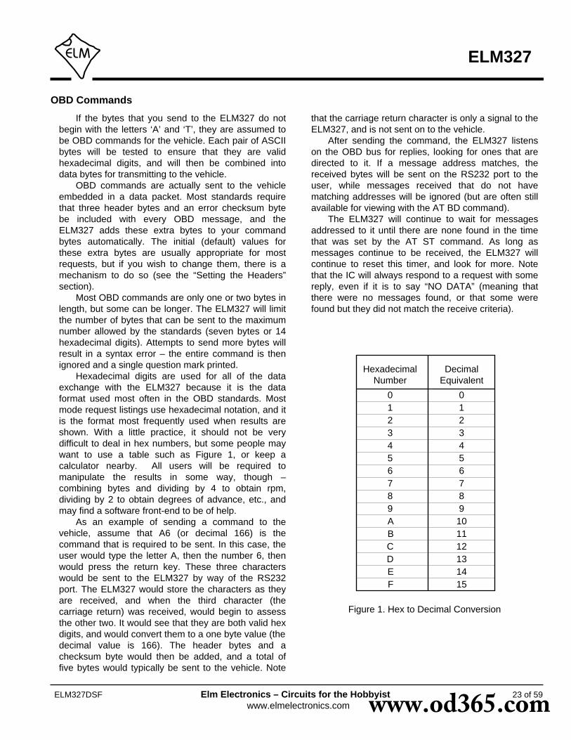
OBD Commands
If the bytes that you send to the ELM327 do notbegin with the letters ‘A’ and ‘T’, they are assumed tobe OBD commands for the vehicle. Each pair of ASCIIbytes will be tested to ensure that they are validhexadecimal digits, and will then be combined intodata bytes for transmitting to the vehicle.
OBD commands are actually sent to the vehicleembedded in a data packet. Most standards requirethat three header bytes and an error checksum bytebe included with every OBD message, and theELM327 adds these extra bytes to your commandbytes automatically. The initial (default) values forthese extra bytes are usually appropriate for mostrequests, but if you wish to change them, there is amechanism to do so (see the “Setting the Headers”section).
Most OBD commands are only one or two bytes inlength, but some can be longer. The ELM327 will limitthe number of bytes that can be sent to the maximumnumber allowed by the standards (seven bytes or 14hexadecimal digits). Attempts to send more bytes willresult in a syntax error – the entire command is thenignored and a single question mark printed.
Hexadecimal digits are used for all of the dataexchange with the ELM327 because it is the dataformat used most often in the OBD standards. Mostmode request listings use hexadecimal notation, and itis the format most frequently used when results areshown. With a little practice, it should not be verydifficult to deal in hex numbers, but some people maywant to use a table such as Figure 1, or keep acalculator nearby. All users will be required tomanipulate the results in some way, though –combining bytes and dividing by 4 to obtain rpm,dividing by 2 to obtain degrees of advance, etc., andmay find a software front-end to be of help.
As an example of sending a command to thevehicle, assume that A6 (or decimal 166) is thecommand that is required to be sent. In this case, theuser would type the letter A, then the number 6, thenwould press the return key. These three characterswould be sent to the ELM327 by way of the RS232port. The ELM327 would store the characters as theyare received, and when the third character (thecarriage return) was received, would begin to assessthe other two. It would see that they are both valid hexdigits, and would convert them to a one byte value (thedecimal value is 166). The header bytes and achecksum byte would then be added, and a total offive bytes would typically be sent to the vehicle. Note
that the carriage return character is only a signal to theELM327, and is not sent on to the vehicle.
After sending the command, the ELM327 listenson the OBD bus for replies, looking for ones that aredirected to it. If a message address matches, thereceived bytes will be sent on the RS232 port to theuser, while messages received that do not havematching addresses will be ignored (but are often stillavailable for viewing with the AT BD command).
The ELM327 will continue to wait for messagesaddressed to it until there are none found in the timethat was set by the AT ST command. As long asmessages continue to be received, the ELM327 willcontinue to reset this timer, and look for more. Notethat the IC will always respond to a request with somereply, even if it is to say “NO DATA” (meaning thatthere were no messages found, or that some werefound but they did not match the receive criteria).
23 of 59
ELM327
ELM327DSF Elm Electronics – Circuits for the Hobbyistwww.elmelectronics.com
Figure 1. Hex to Decimal Conversion
HexadecimalNumber
DecimalEquivalent
01
32
456
01
32
456
7 78 89 9A 10B 11C 12D 13E 14F 15
www.od365.com

Talking to the Vehicle
The OBD standards specify that each request thatis sent to the vehicle must adhere to a set format. Thefirst byte sent (known as the ‘mode’) describes thetype of data being requested, while the second byte(and possibly a third or more) specify the actualinformation that is required. The bytes which followafter the mode byte are known as the ‘parameteridentification’ or PID number bytes. The modes andPIDs are described in detail in documents such as theSAE J1979, or ISO 15031-5 standards, and may alsobe expanded on by the vehicle manufacturers.
Initially, SAE standard J1979 defined nine possiblediagnostic test modes, which are:
01 - show current data02 - show freeze frame data03 - show diagnostic trouble codes04 - clear trouble codes and stored values05 - test results, oxygen sensors06 - test results, non-continuously monitored07 - show ‘pending’ trouble codes08 - special control mode09 - request vehicle information
Recent changes now define a tenth mode thatmay be used with the ISO 15765-4 (CAN) standard.This mode (0A) is used for permanent trouble codes.
Vehicles are not required to support all modes,and within modes, they are not required to support allpossible PIDs (some of the first OBDII vehicles onlysupported a very small number). Within each mode,PID 00 is normally reserved to show which PIDs aresupported by that mode, and can be used to determinewhich ones your vehicle supports.
Mode 01, PID 00 must be supported by allvehicles, and can be accessed as follows…
Ensure that your ELM327 interface is properlyconnected to the vehicle, and powered. Most vehicleswill not respond without the ignition key in the ONposition, so turn the ignition to on, but do not start theengine. At the prompt, issue the mode 01 PID 00command:
>01 00
The first time the bus is accessed, you may see abus initialization message, followed by a response,which might typically be as follows:
41 00 BE 1F B8 10
The 41 signifies a response from a mode 01
request (01 + 40 = 41), while the second number (00)simply repeats the PID number requested. A mode 02,request is answered with a 42, a mode 03 with a 43,etc. The next four bytes (BE, 1F, B8, and 10)represent the requested data, in this case a bit patternshowing the PIDs that are supported by this mode(1=supported, 0=not). Although this information is notvery useful for the casual user, it does prove that theconnection is working.
Another example requests the current enginecoolant temperature (ECT). Coolant temperature isPID 05 in mode 01, and can be requested as follows:
>01 05
The response will be of the form:
41 05 7B
The 41 05 shows that this is a response to amode 1 request for PID 05, while the 7B is the desireddata. Converting the hexadecimal 7B to decimal, onegets 7 x 16 + 11 = 123. This represents the currenttemperature in degrees Celsius, but with the zerooffset to allow for subzero temperatures. To convert tothe actual coolant temperature, you need to subtract40 from the value obtained. In this case, then, thecoolant temperature is 123 - 40 or 83°C.
A final example shows a request for the enginerpm. This is PID 0C of mode 01, so at the prompt type:
>01 0C
A typical response would be:
41 0C 1A F8
The returned value (1A F8) is actually a two bytevalue that must be converted to a decimal value to beuseful. Converting it, we get a value of 6904, whichseems to be a very high value for engine rpm. That isbecause rpm is sent in increments of 1/4 rpm! Toconvert to the actual engine speed, we need to dividethe 6904 by 4. In this case, then, the rpm is 1726,which is much more reasonable.
When the ELM327 sends a request, it also sets atimer that limits the amount of time that the IC will waitfor a response (you can adjust this timer with theAT ST command). If no response is obtained duringthis time, you will see a NO DATA message, and if aresponse is received, it will be printed as we have justseen.
24 of 59
ELM327
ELM327DSF Elm Electronics – Circuits for the Hobbyistwww.elmelectronics.com www.od365.com

Talking to the Vehicle (continued)
25 of 59
ELM327
ELM327DSF Elm Electronics – Circuits for the Hobbyistwww.elmelectronics.com
After the first response has been received andprinted, the timer is reset, and the ELM327 waits tosee if another response is coming. If nothing doesarrive, you will not see a NO DATA response however,as there has been data returned already. On such atimeout, the IC will simply print a prompt character,and wait for the next command from the PC.
This timeout approach means that the ELM327may take almost twice as long as it needs to, in orderto obtain one single answer, then return to the prompt.Unfortunately, there was little that could be done aboutthis with the earlier versions of this IC.
Version 1.3 of the ELM327 introduces one way tospeed up the retrieval of information, if you know howmany responses to expect. You can now tell theELM327 how many responses to obtain beforereturning immediately to the prompt state. This is doneby adding a single hex digit after the OBD requestbytes - the value of the digit providing the maximumnumber of responses to obtain. As an example, if youknow that there is only one response coming for theengine temperature request that was previouslydiscussed, you can now send:
>01 05 1
and the ELM327 will return immediately after obtainingonly one response. It still sets the internal timer aftersending the request, but it only waits for one response- it does not set the timer and wait for a secondresponse, which may save considerable time (thedefault time without adaptive timing being enabled is200 msec).
The number of responses that you provide can beany single hex digit, of value 0 to F. It is not required tobe provided (the old way of doing it is fine - it’s just alittle slower). Note that the AT R0 setting will overrideany number provided with the OBD request. If you tryto obtain more responses than the ECU can provide,the ELM327 will time out as previously, and there is noharm done.
A final example is the request for a vehicle serialnumber, which is discussed in a coming section. Themode for the serial number is 09, while the PID is 02. Ifyou know that the response is to be 5 lines long, timecan be saved by sending:
>09 02 5
Before using this new method of data retrieval, besure to go to the trouble of learning how many
responses are normally sent by your vehicle inresponse to a query. If you should request too few,ignoring the others, you may cause undo congestion ofthe vehicle data bus as a result. For example, theJ1850 PWM protocol requires that every response beacknowledged with what is known as an ‘in frameresponse’ (IFR). If this IFR is not received by thevehicle, it will try to resend the data (many times),hoping to eventually receive an IFR. If you ask for onlyone response, but the vehicle is trying to send 5, youmay cause problems.
Clearly, there needs to be a way to keep track ofhow many responses to expect, and then make theproper requests based on this information. For aperson trying to obtain a few trouble codes, thesavings are not worth the trouble (it’s likely easiest touse the old way to make a request), but for aprogrammer trying to obtain vehicle information asquickly as possible, the time taken is most likely veryworthwhile.
We must present another warning here to be verycautious with how you use this method of querying thevehicle. One direct benefit of the ELM327 returningmore quickly from making a request is that the nextrequest can then begin more quickly. Be aware thatearly versions of the SAE J1979 standard forbidsending requests more frequently than every 100msec, however, and it was only with the APR2002update that scan tools were finally allowed to send thenext request without delay. Furthermore, a request canonly be sent without delay if it is determined that all theresponses have been received. If you are connectedto an older vehicle, you should use the old method ofmaking requests.
Hopefully this has shown how typical requests aremade using the ELM327. It has not been meant to bea definitive guide on modes and PIDs – thisinformation can be obtained from the manufacturer ofyour vehicle, the SAE (http://www.sae.org/), from ISO(http://www.iso.org/), or from various other sources onthe web.
www.od365.com

Interpreting Trouble Codes
Likely the most common use that the ELM327 willbe put to is in obtaining the current Diagnostic TroubleCodes (or DTCs). Minimally, this requires that a mode03 request be made, but first one should determinehow many trouble codes are presently stored. This isdone with a mode 01 PID 01 request as follows:
>01 01
To which a typical response might be:
41 01 81 07 65 04
The 41 01 signifies a response to the request, andthe next data byte (81) is the number of current troublecodes. Clearly there would not be 81 (hex) or 129(decimal) trouble codes present if the vehicle is at alloperational. In fact, this byte does double duty, withthe most significant bit being used to indicate that themalfunction indicator lamp (MIL, or ‘Check EngineLight’) has been turned on by one of this module’scodes (if there are more than one), while the other 7bits of this byte provide the actual number of storedtrouble codes. In order to calculate the number ofstored codes when the MIL is on, simply subtract 128(or 80 hex) from the number.
The above response then indicates that there isone stored code, and it was the one that set the CheckEngine Lamp or MIL on. The remaining bytes in theresponse provide information on the types of testssupported by that particular module (see the SAEdocument J1979 for further information).
In this instance, there was only one line to theresponse, but if there were codes stored in othermodules, they each could have provided a line ofresponse. To determine which module is reporting thetrouble code, one would have to turn the headers on(AT H1) and then look at the third byte of the threebyte header for the address of the module that sentthe information.
Having determined the number of codes stored,the next step is to request the actual trouble codeswith a mode 03 request (there is no PID needed):
>03
A response to this could be:
43 01 33 00 00 00 00
The ‘43’ in the above response simply indicatesthat this is a response to a mode 03 request. The other
6 bytes in the response have to be read in pairs toshow the trouble codes (the above would beinterpreted as 0133, 0000, and 0000). Note that theresponse has been padded with 00’s as required bythe SAE standard for this mode – the 0000’s do notrepresent actual trouble codes.
As was the case when requesting the number ofstored codes, the most significant bits of each troublecode also contain additional information. It is easiest touse the following table to interpret the extra bits in thefirst digit as follows:
Powertrain Codes - SAE defined0
“ “ - manufacturer defined
“ “ - SAE defined
“ “ - jointly defined
1
2
3
If the first hex digit received is this,Replace it with these two characters
Chassis Codes - SAE defined4
“ “ - reserved for future
5
6
7
Body Codes - SAE defined8
9
A
B
Network Codes - SAE definedC
D
E
F
P0
P1
P2
P3
C0
C1
C2
C3
B0
B1
B2
B3
U0
U1
U2
U3
“ “ - reserved for future
“ “ - manufacturer defined
“ “ - manufacturer defined
“ “ - manufacturer defined
“ “ - manufacturer defined
“ “ - manufacturer defined
“ “ - manufacturer defined
“ “ - reserved for future
Taking the example trouble code (0133), the firstdigit (0) would then be replaced with P0, and the 0133reported would become P0133 (which is the code foran ‘oxygen sensor circuit slow response’). Note thatthe ISO 15765-4 (CAN) protocol is very similar, but itadds an extra data byte (in the second position),showing how many data items (DTCs) are to follow.
To provide a few further examples, if the receivedcode was D016, you would replace the D with U1, andthe resulting trouble code would be U1016. Similarly,1131 received would actually be for the code P1131.
26 of 59
ELM327
ELM327DSF Elm Electronics – Circuits for the Hobbyistwww.elmelectronics.com www.od365.com

Resetting Trouble Codes
The ELM327 is quite capable of resettingdiagnostic trouble codes, as this only requires issuinga mode 04 command. The consequences shouldalways be considered before sending it, however, asmore than the MIL (or ‘Check Engine Light’) will bereset. In fact, issuing a mode 04 will:
- reset the number of trouble codes- erase any diagnostic trouble codes- erase any stored freeze frame data- erase the DTC that initiated the freeze frame- erase all oxygen sensor test data- erase mode 06 and 07 information
Clearing of all of this data is not unique to theELM327 – it occurs whenever any scan tool is used toreset the codes. The biggest problem with losing thisdata is that your vehicle may run poorly for a shorttime, while it performs a recalibration.
To avoid inadvertently erasing stored information,the SAE specifies that scan tools must verify that a
mode 04 is intended (“Are you sure?”) before actuallysending it to the vehicle, as all trouble codeinformation is immediately lost when the mode is sent.Remember that the ELM327 does not monitor thecontent of the messages, so it will not know to ask forconfirmation of the mode request – this would have tobe the duty of a software interface if one is written.
As stated, to actually erase diagnostic troublecodes, one need only issue a mode 04 command. Aresponse of 44 from the vehicle indicates that themode request has been carried out, the informationerased, and the MIL turned off. Some vehicles mayrequire a special condition to occur (eg. the ignition onbut the engine not running) before they will respond toa mode 04 command.
That is all there is to clearing trouble codes. Onceagain, do not accidentally send the 04 code!
27 of 59
ELM327
ELM327DSF Elm Electronics – Circuits for the Hobbyistwww.elmelectronics.com
Quick Guide for Reading Trouble Codes
If you do not use your ELM327 for some time, thisentire data sheet may seem like quite a bit to reviewwhen your ‘Check Engine’ light eventually comes on,and you just want to know why. We offer this sectionas a quick guide to the basics that you will need.
To get started, connect the ELM327 circuit to yourPC or PDA and communicate with it using a terminalprogram such as HyperTerminal, ZTerm, ptelnet, or asimilar program. It should normally be set to either9600 or 38400 baud, with 8 data bits, and no parity orhandshaking.
The chart at the right provides a quick procedureon what to do next:
Ignition Key to ON,but vehicle not running
>0101to see how many codes
(2nd digit of the 3rd byte)
>03to see the codes
(ignore the first byte andread the others in pairs)
>04to reset the codes
FIX THE VEHICLE !
www.od365.com
28 of 59
ELM327
ELM327DSF Elm Electronics – Circuits for the Hobbyistwww.elmelectronics.com
Wakeup Messages
After an ISO 9141 or ISO 14230 connection hasbeen established, there needs to be periodic datatransfers in order to maintain that connection, andprevent it from ‘going to sleep.’ If normal requests andresponses are being sent, that is usually sufficient, butthe ELM327 occasionally has to create its ownmessages to prevent the connecton from timing out.
We term these periodic messages that are createdthe ‘Wakeup Messages’, as they keep the connectionalive, and prevent the circuitry from going back to anidle or sleep mode. (Some texts refer to thesemessages simply as ‘idle messages.’) The ELM327automatically creates and sends these for you if thereappears to be no other activity – there is nothing thatyou need do to ensure that they occur. To see these,once a connection is made, simply monitor the OBDtransmit LED – you will see the periodic ‘blips’ createdwhen the ELM327 sends one. If you are curious as tothe actual contents of the messages, you can thenperform a Buffer Dump to see the bytes. Note that theELM327 never obtains or prints a response to any ofthe wakeup messages.
The standards state that if there is no activity atleast every five seconds, the data connection mayclose. To ensure that this does not happen, and to
provide some margin, the ELM327 will send a wakeupmessage after three seconds of inactivity. This timeinterval is fully programmable, should you prefer adifferent setting (see the AT SW command).
As with the ELM323, the ELM327 allows users tochange the actual wakeup message that is sent. To doso, simply send the ELM327 a Wakeup Messagecommand, telling it what you wish the message to bechanged to. For example, if you would like to send thedata bytes 44 55 with the header bytes set to 11 2233, simply send the command:
>AT WM 11 22 33 44 55
and from that point forward, every wakeup messagethat the ELM327 sends will be as shown. You shouldnot provide a checksum byte, as it will be automaticallyadded for you.
You can change these as often as you want, theonly restriction being that every time you do, you mustprovide the complete message – the header bytes andthe data bytes (the current version of the ELM327 onlyallows for messages of one to six bytes in length).
Bus Initiation
Both the ISO 9141-2 and ISO 14230-4 (KWP2000)standards require that the vehicle’s OBD bus beinitialized before any communications can take place.The ISO 9141 standard allows for only a slow (2 to 3second) initiation process, while ISO 14230 allows forboth a slow method, and a faster alternative.
The ELM327 will perform this bus initiation for you,but not until your request needs to be sent. If the businitiation occurs during an automatic search, you willnot see any status reporting, but if you have the Autooption off (and are set to protocols 3, 4, or 5), then youwill see a message similar to this:
BUS INIT: ...
The three dots appear only as the slow initiationprocess is carried out – a fast initiation does not showthe dots. This will be followed by either the expression‘OK’ to say it was successful, or else an error messageto indicate that there was a problem. (The mostcommon error encountered is in forgetting to turn thevehicle’s key to ‘ON’ before attempting to talk to the
vehicle.) Once the bus has been initiated, communications
must take place regularly (typically at least once everyfive seconds), or the bus will revert to a low-power‘sleep’ mode. If you are not sending data requestsoften enough, the ELM327 will generate requests foryou to ensure that the bus stays ‘awake’. You willnever see the responses to these, but you may seethe transmit LED flash periodically when these arebeing sent.
By default, the ELM327 ensures that these‘wakeup’ or ‘idle’ messages are sent every 3 seconds,but this is adjustable with the AT SW command. Thecontents of the wakeup message are also userprogrammable with the AT WM command, if youshould wish to change them. Users generally do nothave to change either of the above though, as thedefault settings work well with almost all systems.
www.od365.com

29 of 59
ELM327
ELM327DSF Elm Electronics – Circuits for the Hobbyistwww.elmelectronics.com
Selecting Protocols
The ELM327 supports several different OBDprotocols (see Figure 2, at right). As a user, you maynever have to choose which one it should use (sincethe factory settings cause an automatic search to beperformed for you), but while experimenting, you maywant to specify which protocol is to be used.
For example, if you know that your vehicle usesthe SAE J1850 VPW protocol, you may want theELM327 to use only that protocol, and no others. Ifthat is what you want, simply determine the protocolnumber (from Figure 2), then use the ‘Set Protocol’ ATCommand as follows:
>AT SP 2OK
From this point on, the default protocol (used afterevery power-up or AT D command) will be protocol 2(or whichever one that you have chosen). Verify thisby asking the ELM327 to describe the protocol:
>AT DPSAE J1850 VPW
Now what happens if your friend has a vehicle thatuses ISO 9141-2? How do you now use the ELM327interface for that vehicle, if it is set for J1850?
One possibility is to change your protocol selectionto allow for the automatic searching for anotherprotocol, on failure of the current one. This is done byputting an ‘A’ with the protocol number, as follows:
>AT SP A2OK
>AT DPAUTO, SAE J1850 VPW
Now, the ELM327 will begin by trying protocol 2,but will then automatically begin searching for anotherprotocol should an attempt to connect with protocol 2fail (as would happen when you try to connect to thefriend’s vehicle).
The Set Protocol commands cause an immediatewrite to the internal EEPROM, before even attemptingto connect to the vehicle. This write is time-consuming,affects the setting for the next powerup, and may notactually be appropriate, if the protocol selected is notcorrect for the vehicle. To allow a test before a writeoccurs, the ELM327 offers one other command - theTry Protocol (TP) command.
Try Protocol is very similar to Set Protocol. It isused in exactly the same way as the AT SP command,the only difference being that a write to internal
memory will only occur after a valid protocol is found,and only if the memory function is enabled (M0/M1).For the previous example, all that needs to be sent is:
>AT TP A2OK
Many times, it is very difficult to even guess at aprotocol to try first. In these cases, it is best to simplylet the ELM327 decide what to use. This is done bytelling it to use protocol 0 (with either the SP or the TPcommands).
To have the ELM327 automatically search for aprotocol to use, simply send:
>AT SP 0OK
and when the next OBD command is to be sent, theELM327 will automatically look for one that responds.You will see a “SEARCHING...” message, followed bya response, after which you can ask the ELM327 whatprotocol it found (by sending AT DP).
The first versions of the ELM327 used the SAErecommended search order (protocol 1, 2, 3, etc.), butrecent versions of the IC modify the search order
Figure 2. ELM327 Protocol Numbers
Description
SAE J1850 PWM (41.6 Kbaud)
Protocol
0
1
2
3
4
5
6
7
8
9
Automatic
SAE J1850 VPW (10.4 Kbaud)
ISO 9141-2 (5 baud init)
ISO 14230-4 KWP (5 baud init)
ISO 14230-4 KWP (fast init)
ISO 15765-4 CAN (11 bit ID, 500 Kbaud)
ISO 15765-4 CAN (29 bit ID, 500 Kbaud)
ISO 15765-4 CAN (11 bit ID, 250 Kbaud)
ISO 15765-4 CAN (29 bit ID, 250 Kbaud)
A
B
C
SAE J1939 CAN (29 bit ID, 250* Kbaud)
User1 CAN (11* bit ID, 125* Kbaud)
User2 CAN (11* bit ID, 50* Kbaud)
*user adjustable
www.od365.com

OBD Message Formats
To this point we have only discussed the contents(data portion) of an OBD message, and made onlypassing mention of other parts such as headers andchecksums, which all messages use to some extent.
On Board Diagnostics systems are designed to bevery flexible, providing a means for several devices tocommunicate with one another. In order for messagesto be sent between devices, it is necessary to addinformation describing the type of information beingsent, the device that it is being sent to, and perhapswhich device is doing the sending. Additionally, theimportance of the message becomes a concern aswell – crankshaft position information is certainly ofconsiderably more importance to a running enginethan a request for the number of trouble codes stored,
30 of 59
ELM327
ELM327DSF Elm Electronics – Circuits for the Hobbyistwww.elmelectronics.com
or the vehicle serial number. So to convey importance,messages are also assigned a priority.
The information describing the priority, theintended recipient, and the transmitter are usuallyneeded by the recipient even before they know thetype of request that the message contains. To ensurethat this information is obtained first, OBD systemstransmit it at the start (or head) of the message. Sincethese bytes are at the head, they are usually referredto as header bytes. Figure 3 below shows a typicalOBD message structure that is used by theSAE J1850, ISO 9141-2, and ISO 14230-4 standards.It uses 3 header bytes as shown, to provide detailsconcerning the priority, the receiver, and thetransmitter. Note that many texts refer to the receiver
Figure 3. An OBD Message
up to 7 data bytes checksum3 header bytes
priority receiver transmitter
TA SA
based on any active inputs that are present. If youneed to follow the SAE J1978 order, you will need toselect each protocol with the SP or TP commands.
The automatic search works well with OBDIIsystems, but may not be what you need if you areexperimenting. During a search, the ELM327 ignoresany headers that you have previously defined (sincethere is always a chance that your headers may notresult in a response), and it uses the default OBDheader values for each protocol. It will also usestandard requests (ie 01 00) during the searches. Ifthis is not what you want, the results may be a littlefrustrating.
To use your own header (and data) values whenattempting to connect to an ECU, do not tell theELM327 to use protocol 0. Instead, tell it to either useonly your target protocol (ie. AT SP n), or else tell it to
Selecting Protocols (continued)
use yours with automatic searches allowed on failure(ie AT SP An). Then send your request, with headersassigned as required. The ELM327 will attempt toconnect using your headers and your data, and only ifit fails (and you have chosen the protocol with the ATSP An method) will it search using the standard OBDdefault values.
In general, 99% of all users find that enabling thememory (setting pin 5 to 5V) and choosing the ‘Auto’option the first time (the easiest way is to say AT SP 0)works very well. After the initial search, the protocolused by your vehicle becomes the new default (so it istried first every time), and if the interface is used onanother vehicle, there is only a minor delay while itperforms an automatic search.
www.od365.com

31 of 59
ELM327
ELM327DSF Elm Electronics – Circuits for the Hobbyistwww.elmelectronics.com
Figure 4. A CAN OBD Message
as the “Target Address” (TA), and the transmitter asthe “Source Address” (SA).
Another concern when sending any message isthat errors might occur in the transmission, and thereceived data may be falsely interpreted. To detecterrors, the various protocols all provide some form ofcheck on the received data. This may be as simple asa sum calculation (ie a ‘running total’ of byte values)that is sent at the end of a message. If the receiveralso calculates a sum as bytes are received, then thetwo values can be compared and if they do not agree,the receiver will know that an error has occured. Sincesimple sums might not detect multiple errors, a morereliable (and more complicated) sum called a CyclicRedundancy Check (or ‘CRC’) is often used. All of theprotocols specify how errors are to be detected, andthe various ways of handling them if they occur.
The OBD data bytes are thus normallyencapsulated within a message, with ‘header’ bytes atthe beginning, and a ‘checksum’ at the end. TheJ1850, ISO 9141-2, and ISO 14230-4 protocols all useessentially the same structure, with three headerbytes, a maximum of seven data bytes and onechecksum byte.
The ISO 15765-4 (CAN) protocol uses a verysimilar structure (see Figure 4, below), the main
OBD Message Formats (continued)
difference really only relating to the structure of theheader. CAN header bytes are not referred to asheader bytes – they are called ‘ID bits’ instead. Theinitial CAN standard defined the ID bits as being 11 innumber, while the more recent CAN standard nowallows for 11 or 29 bit IDs.
The ELM327 does not normally show any of theseextra bytes unless you turn that feature on with theHeaders On command (AT H1). Issuing that allowsyou to see the header bytes and the checksum byte(for the J1850, ISO 9141 and ISO 14230 protocols).For the CAN protocols, you will see the ID bits, andother items which are normally hidden such as the PCIbyte for ISO 15765, or the data length codes (if theyare enabled with PP 29, or AT D1). Note that theELM327 does not display the checksum informationfor CAN systems, or the IFR bytes for J1850 systems.
It is not necessary to ever have to set theseheader byes, or to perform a checksum calculation, asthe ELM327 will always do this for you. The headerbytes are adjustable however, should you wish toexperiment by using advanced techniques such asphysical addressing. The next section provides adiscussion on how to do this…
ID bits (11 or 29) 7 data bytes checksumPCI
data bytes (8 in total)“header” bytes
www.od365.com

Setting the Headers
The emissions related diagnostic trouble codesthat most people are familiar with are described in theSAE J1979 standard (ISO15031-5). They representonly a portion of the data that a vehicle may haveavailable – much more can be obtained if you are ableto direct the requests elsewhere.
Accessing most OBDII diagnostics informationrequires that requests be made to what is known as aa ‘functional address.’ Any processor that supports thefunction will respond to the request (and theoretically,many different processors can respond to a singlefunctional request). In addition, every processor (orECU) will also respond to what is known as theirphysical address. It is the physical address thatuniquely identifies each module in a vehicle, andpermits you to direct more specific queries to only oneparticular module.
To retrieve information beyond that of the OBDIIrequirements then, it will be necessary to direct yourrequests to either a different functional address, or toan ECU’s physical address. This is done by changingthe data bytes in the message header.
As an example of functional addressing, let usassume that you want to request that the processorresponsible for Engine Coolant provide the currentFluid Temperature. You do not know its address, soyou consult the SAE J2178 standard and determinethat Engine Coolant is functional address 48. SAEstandard J2178 also tells you that for your J1850 VPWvehicle, a priority byte of A8 is appropriate. Finally,knowing that a scan tool is normally address F1, youhave enough information to specify the three headerbytes (A8 48 and F1). To tell the ELM327 to use thesenew header bytes, all you need is the Set Headercommand:
>AT SH A8 48 F1OK
The three header bytes assigned in this mannerwill stay in effect until changed by the next AT SHcommand, a reset, or an AT D.
Having set the header bytes, you now need onlysend the secondary ID for fluid temperature (10) at theprompt. If the display of headers is turned off, theconversation could look like this:
>1010 2E
The first byte in the response echos the request,as usual, while the data that we requested is the 2E
byte. You may find that some requests, being of a lowpriority, may not be answered immediately, possiblycausing a “NO DATA” result. In these cases, you maywant to adjust the timeout value, perhaps first tryingthe maximum (ie use AT ST FF). Many vehicles willsimply not support these extra addressing modes.
The other, and more common method of obtaininginformation is by physical addressing, in which youdirect your request to a specific device, not to afunctional group. To do this, you again need toconstruct a set of header bytes that direct your queryto the physical address of the processor, or ECU. Ifyou do not know the address, recall that the sender ofinformation is usually shown in the third byte of theheader. By monitoring your system for a time with theheaders turned on (AT H1), you can quickly learn themain addresses of the senders. The SAE documentJ2178 assigns address ranges to these devices if youare unsure of which might be most appropriate.
When you know the address that you wish to‘speak to,’ simply use it for the second byte in theheader (assume an address of 10 for this example).Combine that with your knowledge of SAE J2178 tochoose a priority/type byte (assume a value of E4 forthis example, as if the vehicle is J1850 PWM). Finally,you need to identify yourself to the target, so thatresponses can be returned to you. As is customary fordiagnostic tools, we’ll use an address of F1. As before,these three bytes are then assigned to the header withthe set header command:
>AT SH E4 10 F1OK
From this point on, all messages that the ELM327sends will use these three bytes for the header. All thatneeds to be done now is to request data from thevehicle. For physical addressing, this is often doneusing mode 22:
>22 11 6B62 11 6B 00 00
The response to this command is of the sameformat to those seen for ‘standard’ OBD requests. Therequest has been repeated (with 40 added to themode value in order to show that this is a response),and this is followed by the actual data (0000 in thiscase). The PIDs used with mode 22 are usuallyproprietary to each manufacturer and are generally notpublished widely, so you may have difficulty indetermining the ones to use with your vehicle. Elm
32 of 59
ELM327
ELM327DSF Elm Electronics – Circuits for the Hobbyistwww.elmelectronics.com www.od365.com

Setting the Headers (continued)
33 of 59
ELM327
ELM327DSF Elm Electronics – Circuits for the Hobbyistwww.elmelectronics.com
>AT SH xx yy zz>AT CP vv
vv xx yy zz
5 bits only
xx yy zzvv
29 bit ID
Figure 5. Setting a 29 bit (extended) CAN ID
Electronics does not maintain lists of this information,and cannot provide any further details for you. Mode22 and others are described in more detail in SAEdocument J2190, “Enhanced E/E Diagnostic TestModes”.
The ISO14230-4 standard defines its’ headerbytes a little differently. Advanced experimenters willbe aware that for ISO 14230-4, the first header bytemust always include the length of the data field, whichvaries from message to message. From that, onemight assume that the you would need to redefine theheader for every message that is to be sent – not so!The ELM327 always determines the number of bytesthat you are sending, and inserts that length for you, inthe proper place for the header that you are using. Ifyou are using the standard ISO 14230-4 header, thelength will be put into the first header byte, and youneed only provide the two (most significant) bits of thisbyte when defining the header. What you place in therest of the byte will be ignored by the ELM327 unlessyou set it to 0. If it is 0, it is assumed that you areexperimenting with KWP four byte headers, and theELM327 then creates the fourth header byte for you.Again, you do not need to provide any length to be putinto this byte – it is done for you.
Addressing within the CAN (ISO 15765-4)protocols is quite similar in many ways. First, considerthe 29 bit standard. The ELM327 splits the 29 bits intoa CAN Priority byte and the three header bytes that weare now familiar with. Figure 5 shows how these arecombined for use by the ELM327.
The CAN standard states that for diagnostics, thepriority byte (‘vv’ in the diagram) will always be 18 (this
xx yy zz
11 bit ID
Figure 6. Setting an 11 bit (standard) CAN ID
is the default value used by the ELM327). Since it israrely changed, it is assigned separately from theother header bytes, using the CP command. Changingof this value is usually only required if experimentingwith J1939 systems.
The next byte (‘xx’) describes the type of messagethat this is, and is set to hex DB for functionaladdressing, and to DA if using physical addressing.The next two bytes are as defined previously for theother standards – ‘yy’ is the receiver (or TargetAddress), and ‘zz’ is the transmitter (or SourceAddress). For the functional diagnostic requests, thereceiver is always 33, and the transmitter is F1, whichis very similar to ISO 14230-4.
Those that are familiar with the SAE J1939standard will likely find this header structure to be veryfamiliar (J1939 is a CAN standard for use by ‘heavy-duty vehicles’ such as trucks and buses). It usesslightly different terminology, but there is a directparallel between the bytes used by J1939 for theheaders and the grouping of the bytes in the ELM327.Refer to page 41 for a discussion of the J1939 supportthat is provided by the ELM327.
The final header format to discuss is that used in11 bit CAN systems. They also use a priority/addressstructure, but shorten it into roughly three nibblesrather than three bytes. The ELM327 uses the samecommands to set these values as for other headers,except that it only uses the 11 least significant (‘right-most’) bits of the provided header bytes, and ignoresthe others (as shown in Figure 6). It quickly becomesinconvenient to have to enter six digits when only threeare required, so there is a special ‘short’ version of the
>AT SH xx yy zz
www.od365.com

34 of 59
ELM327
ELM327DSF Elm Electronics – Circuits for the Hobbyistwww.elmelectronics.com
Setting the Headers (continued)
AT SH command that uses only three hex digits. Itactually operates by simply adding the leading zeroesfor you.
The 11 bit CAN standard typically makesfunctional requests (ID/header = 7DF), but receivesphysical replies (7En). With headers turned on, it is asimple matter to learn the address of the module thatis replying, then use that information to make physicalrequests if desired. For example, if the headers are on,and you send 01 00, you might see:
>01 007E8 06 41 00 BE 3F B8 13 00
The 7E8 shows that ECU#1 was the oneresponding. In order to talk directly to that ECU, all youneed do is to set the header to the appropriate value (itis 7E0 to talk to the 7E8 device – see ISO 15765-4 formore information). From that point on, you can ‘talk’directly to the ECU using its physical address, asshown here:
>AT SH 7E0OK
>01 057E8 03 41 05 46 00 00 00 00
Hopefully this has helped to get you started. As weoften tell those that write – if you are planning to dosome serious experimenting with OBD, you should buythe relevant standards.
www.od365.com

Monitoring the Bus
Some vehicles use the OBD bus for informationtransfer during normal vehicle operation, passing agreat deal of information over it. A lot can be learned ifyou have the good fortune to connect to one of thesevehicles, and are able to decipher the contents of themessages.
To see how your vehicle uses the OBD bus, youcan enter the ELM327’s ‘Monitor All’ mode, by sendingthe command AT MA from your terminal program. Thiswill cause the IC to display any information that it seeson the OBD bus, regardless of transmitter or receiveraddresses (it will show all). Note that the ELM327remains silent while monitoring, so periodic ‘wakeup’messages are not sent (if you have an ISO 9141 orISO 14230 bus that had been initialized previously, itmay ‘go to sleep’), IFRs are not sent, and the CANmodule does not acknowledge messages.
The monitoring mode can be stopped by putting alogic low level on the RTS pin, or by sending a singleRS232 character to the ELM327. Any convenientcharacter can be used to interrupt the IC – there areno restrictions on whether it is printable, etc. Note thatthe character you send will be discarded, and will haveno effect on any subsequent commands. The time ittakes to respond to this interrupting character willdepend on what the ELM327 is doing when thecharacter is received. The IC will always finish a taskthat is in progress (printing a line, for example) beforereturning to wait for input, so you should always waitfor the prompt character (‘>’), or the Busy line to golow, before beginning to send a command.
One unexpected result may occur if you have theautomatic protocol search feature enabled, and youtell the ELM327 to begin monitoring. If the bus is quiet,the ELM327 will begin searching for an active protocol,which may not be what you were expecting. Be awarealso that the ISO 9141 and ISO 14230 protocols lookidentical when monitoring, so the ELM327 will likelystop searching at ISO 9141, even if the actual protocolis ISO 14230. With the Automatic searching enabled,this should correct itself, however, when an OBDrequest is later made.
If the ‘Monitor All’ command provides too muchinformation (it certainly does for most CAN systems!),then you can restrict the range of data that is to bedisplayed. Perhaps you only want to see messagesthat are being transmitted by the ECU with address 10.To do that, simply type:
>AT MT 10
and all messages that contain 10 in the third byte ofthe header will be displayed.
Using this command with 11 bit CAN systems canbe a little confusing at first. Recall the way in which allheader bytes are stored within the ELM327. An 11 bitCAN ID is actually stored as the least significant 11bits in the 3 byte ‘header storage’ location. It will bestored with 3 bits in the receiver’s address location,and the remaining 8 bits in the transmitter’s addresslocation. For this example, we have requested that allmessages created by transmitter ‘10’ be printed, so all11 bit CAN IDs that end in 10 will be displayed (ie allthat look like ‘x10’).
The other monitoring command that is very usefulis the AT MR command, which looks for specificaddresses in the middle byte of the header. Using thiscommand, you can look for all messages being sent toa particular address. For example, to use it to look formessages being sent to the ECU with address 10,simply send:
>AT MR 10
and all messages that contain 10 in the second byte ofthe header will be displayed.
Using this command with the 11 bit CAN systemswill again need further explanation. It may be helpful tofirst picture the hex number ‘10’ in the above exampleas the binary number ‘0001 0000’. Recall from abovethat 11 bit CAN IDs are actually stored as the leastsignificant 11 bits in the 3 byte ‘header storage’locations, and only 3 bits are actually stored in themiddle byte (receiver’s address) position. Whencomparing the received CAN ID to the address youprovide with the MR command then, only the right-most 3 bits of your MR address are considered andthe other 5 bits are ignored. In this example, theAT MR 10 effectively becomes AT MR 0 for 11 bitCAN systems, and all messages that begin with ‘0’ asthe first digit will actually be displayed.
In order to use the AT MR command with CAN 11bit identifiers, you should always try to use the format‘AT MR 0x’, where ‘x’ is the digit that you want theidentifiers to begin with. To look for all 2xx’s, use thecommand ‘AT MR 02’, and to see all of the 7xx’s, youshould use ‘AT MR 07’.
The ELM327 can be set to automatically send theMonitor All command to itself after power on, if PP 00is set to the value 0, and enabled.
ELM327
35 of 59ELM327DSF Elm Electronics – Circuits for the Hobbyistwww.elmelectronics.com www.od365.com
CAN Messages and Filtering
The ELM327 monitoring commands allow forsome filtering of the information (with AT MR and MT),but those commands still only allow one byte to bedefined, of all the header bits. With CAN systems, thelarge volume of information present may mean thatthis is not precise enough, and there needs to be abetter means of being more selective.
The ELM327’s internal CAN module has a ‘filter’that can be used to select all of the ID bits, not just onebyte of them. The easiest way to use this filter is withthe CRA command. For example, if the only messagesthat you wish to see are those that have the CAN ID7E9, then simply send:
>AT CRA 7E9
and the ELM327 will set internal values so that all thatis displayed are messages with ID 7E9.
If you do not want to define all 11 or 29 bits, arange of values can also be defined, but that requiresalso setting a ‘mask’, in addition to the filter.
As an example, consider an application where youare trying to monitor for 29 bit CAN diagnosticmessages, exactly like the ELM327 does. Bydefinition, these messages will be sent to the scan toolat address F1, so from ISO 15765-4, you know thatthe ID portion of the reply must be of the form:
18 DA F1 xx
where xx is the address of the module that is sendingthe message. To use the filter, enter what you haveinto it, putting anything in for the unknown portion (youwill see why in a moment). The command to set theCAN filter is AT CF:
>AT CF 18 DA F1 00
How, do you tell the ELM327 to ignore those lasttwo 0’s? You do that with the mask. The mask is a bitpattern that tells the ELM327 which bits in the filter arerelevant. If the mask bit is 1, that filter bit is relevant,and is required to match. If it is 0, then that filter bit willbe ignored. All bits in the above message are relevant,except those of the last two digits. To set this maskthen, you would need to use the CAN Mask command,as follows:
>AT CM 1F FF FF 00
The 11 bit CAN IDs are treated in the samemanner. Recall that they are stored internally in the
36 of 59
ELM327
ELM327DSF Elm Electronics – Circuits for the Hobbyistwww.elmelectronics.com
right-most 11 bits of the locations used for 29 bit CAN,which must be considered when creating a filter ormask. As an example, assume that we wish to displayall messages that have a 6 as the first digit of the 11bit ID. We need to set a filter to look for 6 in that digit:
>AT CF 00 00 06 00
The 11 bit ID is stored in the last three locations,so the 6 would appear where it is shown. Now, tomake that digit relevant, we create the mask:
>AT CM 00 00 0F 00
The system only uses the 11 right-most bits in thiscase, so we can be lazy and enter the F as shown (thefirst bit of the F will be ignored, and it will be treated asif we had entered a 7).
Clearly, this can be quite cumbersome if using 11bit CAN systems routinely. To help with that, theELM327 offers some shorter versions of the CF andCM commands. To use them for the example above,you need only enter three digit arguments:
>AT CF 600
and
>AT CM F00
As for the 29 bit versions, only the 11 least significant(right-most) digits are actually used, so you do notneed to take special care with the first bit.
With a little practice, these commands are fairlyeasy to master. Initially, try entering the filter and maskvalues, then use a command such as AT MA to seewhat the results are. The ELM327 knows that you aretrying to filter, and combines the effects of bothcommands (it will do that for MR and MT as well). TheMA, MR and MT commands all have the extra benefitthat while they are in effect, the ELM327 will remainquiet, not sending acknowledgement or error signals,so anything you do while monitoring should not disruptother devices that are on the bus.
Note that if a filter has been set, it will be used forall CAN messages, so setting filters and masks maycause standard OBD requests to be ignored, and youmay begin seeing “NO DATA” responses. If thishappens, and you are unsure of why, you may want toreset everything to their default values (with AT D) andstart over.
www.od365.com

37 of 59
ELM327
ELM327DSF Elm Electronics – Circuits for the Hobbyistwww.elmelectronics.com
Multiline Responses
There are occasions when a vehicle must respondwith more information than one ‘message’ is able toshow. In these cases, it responds with several lineswhich must be assembled into one complete message.
One example of this is a request for the serialnumber of the vehicle (mode 09, PID 02). This is oftena multiline reply that needs to be joined. In thesesituations, you must take care to ensure that all of thereply has been received and it is in the correct orderbefore assembling the message. The actual responseusually has a byte that shows the sequence of thedata, to help with this. Here is one example for atypical SAE J1850 vehicle:
>090249 02 01 00 00 00 3149 02 02 44 34 47 5049 02 03 30 30 52 3549 02 04 35 42 31 3249 02 05 33 34 35 36
Note that all OBD compliant vehicles do notnecessarily provide this information. Many older onesdo not, but as a rule the newer ones do. If your vehicledoes not support this parameter, you will only see a“NO DATA” response.
The first two bytes (49 and 02) on each line of theabove response do not show any vehicle information.They only show that this is a response to an 09 02request. The next byte on each line shows the order inwhich the data is to be assembled. Assembling theremainder of the data in that order, and ignoring thefirst few 00’s gives:
31 44 34 47 50 30 30 52 35 35 42 31 3233 34 35 36
Using an ASCII table to convert these hex digitsgives the following serial number for the vehicle:
1 D 4 G P 0 0 R 5 5 B 1 2 3 4 5 6
CAN systems will display this information in asomewhat different fashion. Here is a typical responsefrom a CAN vehicle:
>09020140: 49 02 01 31 44 341: 47 50 30 30 52 35 352: 42 31 32 33 34 35 36
CAN Formatting has been left on (the default),making the reading of the data easier. With formattingon, the sequence numbers are shown with a colon (‘:’)after each, so that they clearly stand out (0:, 1:, etc.).CAN systems add this hex digit (it goes from 0 to Fthen repeats), to aid in reassembling the data, just asthe J1850 vehicle did.
The first line of this response says that there are014 bytes of information to follow. That is 14 inhexadecimal, or 20 in decimal terms, which agreeswith the 6 + 7 + 7 bytes shown on the three lines.Serial numbers are generally 17 digits long however,so how do we assemble the number from 20 digits?
The second line shown begins with the familiar 4902, as this is a response to an 09 02 request. Clearlythey are not part of the serial number. CAN willoccasionally add a third byte to the response which wesee next (the ‘01’), which shows the number of dataitems that are to follow (the vehicle can only have oneVIN, so the response says there is only one data item).That third byte can be ignored, so this leaves 17 databytes which are the serial number (purposely chosento be identical to the those of the previous example).All that is needed is a conversion to ASCII, in order toread them, exactly as before.
The following shows an example of a different typeof multiline response that can occur when two or moreECUs respond to one request. Here is a typicalresponse to an 01 00 request:
>01 0041 00 BE 3E B8 1141 00 80 10 80 00
This is difficult to decipher without knowing a littlemore information. We need to turn the headers on toactually see ‘who’ is doing the talking:
>AT H1OK
>01 0048 6B 10 41 00 BE 3E B8 11 FA48 6B 18 41 00 80 10 80 00 C0
Now, if you analyze the header, you can see thatthe third byte shows ECU 10 (the engine controller)and ECU 18 (the transmission) are both respondingwith a reply that is valid for them. This type ofresponse occurs often, and you should be prepared forit.
A final example shows how similar messages
www.od365.com

38 of 59
ELM327
ELM327DSF Elm Electronics – Circuits for the Hobbyistwww.elmelectronics.com
Multiline Responses (continued)
might occasionally be ‘mixed up’ in a CAN system. Weask the vehicle for the Calibration ID (09 04) and arepresented with the following response:
>09 040130: 49 04 01 35 36 301: 32 38 39 34 39 41 430130: 49 04 01 35 36 302: 00 00 00 00 00 00 311: 32 38 39 35 34 41 432: 00 00 00 00 00 00 00
which is quite confusing. The first group (the 013, 0:, 1:group) seems to make some sense, but the followinggroup is very confusing. Why are there two segmenttwos? Which ECU do these belong to? The only wayto tell is to turn on the headers, and repeat yourrequest:
>AT H1OK
>09 047E8 10 13 49 04 01 35 36 307E8 21 32 38 39 34 39 41 437E9 10 13 49 04 01 35 36 307E8 22 00 00 00 00 00 00 317E9 21 32 38 39 35 34 41 437E9 22 00 00 00 00 00 00 00
This time, the order appears to be the same, butbe aware that it may not be – that is why the standardrequires that sequence codes be transmitted withmultiline responses.
Looking at the first digits of these responses, youcan see that some begin with 7E8, and some beginwith 7E9. This is the special CAN IDs representingECU#1 and ECU#2, respectively. Grouping theresponses from the two ECUs gives:
7E8 10 13 49 04 01 35 36 307E8 21 32 38 39 34 39 41 437E8 22 00 00 00 00 00 00 31
and7E9 10 13 49 04 01 35 36 307E9 21 32 38 39 35 34 41 437E9 22 00 00 00 00 00 00 00
From these, the messages can be assembled intheir proper order. To do this, look at the byte following
the CAN ID - it is what is known as the PCI byte, andis used to tell what type of data follows. In this case,the PCI byte begins with either a 1 (for a ‘First Frame’message), or a 2 (for the ‘Consecutive Frames’). Thesecond half of the PCI byte shows the order in whichthe information is to be assembled (ie. the segmentnumber). In this case, the segment numbers arealready in order, but if they had not been, it wouldhave been necessary to rearrange the messages toplace them in order.
Each OBD standard has some minor peculiarities.Hopefully this has helped you with some of the moredifficult ones. If you are still having trouble, we urgeyou to purchase the relevant standard, and study it.
www.od365.com

CAN Message Formats
The ISO 15765-4 (CAN) standard defines severalmessage types that are to be used with diagnosticsystems. Currently, there are four main ones that maybe used:
SF - the Single Frame
FF - the First Frame (of a multiframe message)
CF - the Consecutive Frame ( “ “ )
FC - the Flow Control frame
The Single Frame message contains storage forup to seven data bytes and what is known as a PCI(Protocol Control Information) byte. The PCI byte isalways the first byte of them all, and tells how manydata bytes are to follow. If the CAN Auto Formattingoption is on (CAF1) then the ELM327 will create thisbyte for you when sending, and remove it for you whenreceiving. (If the headers are enabled, you will alwayssee it.)
If you turn the Auto Formatting off (with CAF0), itis expected that you will provide all of the data bytes tobe sent. For diagnostics systems, this means the PCIbyte and the data bytes. The ELM327 will not modifyyour data in any way, except to add extra paddingbytes for you, to ensure that you always send as manydata data bytes as are required (eight for ISO15765).You do not need to set the Allow Long (AT AL) optionin order to send eight bytes, as the IC overrides it foryou.
A First Frame message is used to say that amultiframe message is about to be sent, and tells thereceiver just how many data bytes to expect. Thelength descripter is limited to 12 bits, so a maximum of4095 byes can be received at once using this method.
Consecutive Frame messages are sent after theFirst Frame message to provide the remainder of thedata. Each Consecutive Frame message includes asingle hex digit ‘sequence number’ that is used todetermine the order when reassembling the data. It isexpected that if a message were corrupted and resent,it could be out of order by a few packets, but not bymore than 16, so the single digit is normally more thanadequate. As seen previously, the serial number for avehicle is often a multiframe response:
>09020140: 49 02 01 31 44 341: 47 50 30 30 52 35 352: 42 31 32 33 34 35 36
In this example, the line that begins with 0: is theFirst Frame message. The length (014) was actuallyextracted from the message by the ELM327 andprinted on the first line as shown. Following the FirstFrame line are two Consecutive Frames (that beginwith 1: and 2:). To learn more details of the exactformatting, you may want to send a request such asthe one above, then repeat the same request with theheaders enabled (AT H1). This will show the PCI bytesthat are actually used to send these components of thetotal message.
The Flow Control frame is one that you do notnormally have to deal with. When a First Framemessage is sent as part of a reply, the ELM327 musttell the sender some technical things (such as howlong to delay between Consecutive Frames, etc.) anddoes so by replying immediately with a Flow Controlmessage. These are predefined by the ISO 15765-4standard, so can be automatically inserted for you. Ifyou wish to generate custom Flow Control messages,then refer to the next section.
If a Flow Control frame is detected whilemonitoring, the line will be displayed with ‘FC: ’ beforethe data, to help you with decoding of the information.
There is a final type of message that isoccasionally reported, but is not supported by thediagnostics standard. The (Bosch) CAN standardallows for the transmission of a data request withoutsending any data in the requesting message. Toensure that the message is seen as such, the senderalso sets a special flag in the message (the RTR bit),which is seen at each receiver. The ELM327 alwayslooks for this flag, or for zero data bytes, and mayreport to you that an RTR was detected whilemonitoring. This is shown by the characters RTRwhere data would normally appear, but only if the CANAuto Formatting is off, or headers are enabled. Often,when monitoring a CAN system with an incorrect baudrate chosen, RTRs may be seen.
Note that the CAN system is quite robust withseveral error detecting methods in place, so thatduring normal data transmission you will rarely seeany errors. When monitoring buses however, you maywell see errors (especially if the ELM327 is set to anincorrect baud rate). As a diagnostic aid, when errorsdo occur, the ELM327 will print all bytes (no matterwhat CAF, etc., is set to), followed by the message‘<RX ERROR’.
ELM327
39 of 59ELM327DSF Elm Electronics – Circuits for the Hobbyistwww.elmelectronics.com www.od365.com
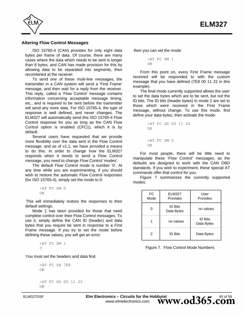
40 of 59ELM327DSF Elm Electronics – Circuits for the Hobbyistwww.elmelectronics.com
Altering Flow Control Messages
ELM327
ISO 15765-4 (CAN) provides for only eight databytes per frame of data. Of course, there are manycases where the data which needs to be sent is longerthan 8 bytes, and CAN has made provision for this byallowing data to be separated into segments, thenrecombined at the receiver.
To send one of these multi-line messages, thetransmitter in a CAN system will send a ‘First Frame’message, and then wait for a reply from the receiver.This reply, called a ‘Flow Control’ message containsinformation concerning acceptable message timing,etc., and is required to be sent before the transmitterwill send any more data. For ISO 15765-4, the type ofresponse is well defined, and never changes. TheELM327 will automatically send this ISO 15765-4 FlowControl response for you as long as the CAN FlowControl option is enabled (CFC1), which it is bydefault.
Several users have requested that we providemore flexibility over the data sent in the Flow Controlmessage, and as of v1.1, we have provided a meansto do this. In order to change how the ELM327responds when it needs to send a Flow Controlmessage, you need to change Flow Control ‘modes’.
The default Flow Control mode is number ‘0’. Atany time while you are experimenting, if you shouldwish to restore the automatic Flow Control responses(for ISO 15765-4), simply set the mode to 0:
>AT FC SM 0OK
This will immediately restore the responses to theirdefault settings.
Mode 1 has been provided for those that needcomplete control over their Flow Control messages. Touse it, simply define the CAN ID (header) and databytes that you require be sent in response to a FirstFrame message. If you try to set the mode beforedefining these values, you will get an error:
>AT FC SM 1?
You must set the headers and data first:
>AT FC SH 7E8OK
>AT FC SD 00 11 22OK
then you can set the mode:
>AT FC SM 1OK
From this point on, every First Frame messagereceived will be responded to with the custommessage that you have defined (7E8 00 11 22 in thisexample).
The final mode currently supported allows the userto set the data bytes which are to be sent, but not theID bits. The ID bits (header bytes) in mode 2 are set tothose which were received in the First Framemessage, without change. To use this mode, firstdefine your data bytes, then activate the mode:
>AT FC SD 00 11 22OK
>AT FC SM 2OK
For most people, there will be little need tomanipulate these ‘Flow Control’ messages, as thedefaults are designed to work with the CAN OBDstandards. If you wish to experiment, these special ATcommands offer that control for you.
Figure 7 summarizes the currently supportedmodes:
Figure 7. Flow Control Mode Numbers
ELM327Provides
FCMode
0
1
2
ID BitsData Bytes
UserProvides
ID Bits Data Bytes
no values
no values
ID BitsData Bytes
www.od365.com

ELM327
41 of 59ELM327DSF Elm Electronics – Circuits for the Hobbyistwww.elmelectronics.com
J1939 Support
The SAE J1939 CAN standard is a relatively newprotocol that is being used in many types of heavymachinery – trucks, agricultural equipment, andbusses, to name a few. It uses a standard CAN(ISO 11898) physical interface, and defines its ownformat for data transfer (although it is very similar tothe ISO 15765 standard that is used for automobiles).
The ELM327 offers some support for the J1939standard in Protocol A. (Protocols B and C may alsobe selected for J1939 formatting if needed, withProgrammable Parameters 2C and 2E). Although thisis not full support as dictated by the standards, theELM327 implementation should at least allow you tobegin experimenting.
The default data rate for Protocol A has been setto 250 kbps, as is required by the SAE J1939-11standard. Should your application require a differentbaud rate, it is easily changed with PP 2B.
J1939 messages use 29 bit CAN IDs, and up to 8data bytes for each message (ISO 15765 always uses8 bytes). Diagnostics on SAE J1939 are defined by theJ1939-73 standard, and the actual data transferprotocol is described in J1939-21. If you are going todo a lot of work with J1939, it may be wise to purchasethese standards documents from the Society ofAutomotive Engineers (SAE).
The ELM327 handles the sending of messageswith the J1939 protocol in the same way that it doesthe other protocols. The header bytes have beenpredefined for you (to send a global request for PGNdata), and all you need do is provide the PGN numberas data bytes.
For example, assume that you wish to send arequest for engine temperature (which is PGN00FEEE). Simply send the request as you would anyother OBD request:
>00 FE EE
When it receives these bytes, the ELM327 addsthe required header (ID) bytes, etc. and sends themessage for you. It then configures itself to be able toreceive a response, and prints out anything that itsees.
If you wish to send a request to a specific addressrather than globally, you will need to change theheader bytes to that address prior to requesting thedata. Setting these bytes is done in exactly the sameway as with other protocols - with the AT SHcommand. For example, the if you wish to send arequest directly to Engine #1 (address 00), from the
scan tool (F9), you would simply send the commandAT SH EA 00 F9 prior to sending any data. After that,all data will be directed to the engine, so don’t forget toreset the headers if you wish to again make globalrequests. Note that the ELM327 does not negotiate fora bus address (per J1939-81), and always uses theaddress set by the header bytes.
If you are familiar with the standard, you will noticethat J1939 actually specifies a reverse order for thedata bytes (the above request should actually be sentas EE FE 00), but this can be very confusing, so theELM327 automatically reverses the order for you. Thisfeature can be disabled at any time with the AT JScommand.
All responses to a request are printed by theELM327, whether they are a single CAN message, ora multisegment transmission as defined by thetransport protocol (J1939-21). If the responses aremultisegment, the ELM327 handles all of thenegotiation for you (transparently - you won’t see ithappen). Note that if you provide three data bytes inthe request, the ELM327 will assume that you aresending a PGN, and will look for responses to that. Ifyou send other than 3 data bytes, it will assume thatyou are making a general request, and it will only lookfor responses to the Source Address (as given in thethird byte of the header).
The SAE J1939 standard predefines severalDiagnostic Messages, and assigns ID values to them.The first of these (designated ‘DM1’) is reserved fortrouble codes, which are periodically broadcast overthe CAN network. Since these are commonly required,the ELM327 provides a special command to monitorfor them (aptly named DM1). If you wish to monitor forall DM1 messages, simply issue:
>AT DM1
and the ELM327 will print out all that it finds.The DM1 message is the only one that is presently
predefined by the ELM327 for you. To monitor for anyother diagnostic message, you need to know it’s PGNnumber (in hexadecimal), and monitor for that usingthe AT MP command. For example, the DM2 PGNnumber is 65227, or 00FECB in hexadecimal, so tomonitor for DM2s, you need only send:
>AT MP 00FECB
and the IC will begin looking for all replies to DM2requests. Since PGNs presently all begin with 00, you
www.od365.com

ELM327
42 of 59ELM327DSF Elm Electronics – Circuits for the Hobbyistwww.elmelectronics.com
J1939 Support (continued)
may find it easier to simply type a shorter version ofthis command:
>AT MP FECB
and have the ELM327 automatically add the two zerosfor you. This shorter version of the command ispresented as a convenience, and is equivalent to theother version.
Received messages are presented in a slightlydifferent way with the J1939 protocols, when theautomatic formating option is selected (it is by default).As an example, we will reset the IC, then set theprotocol to J1939, and then turn the display of headerson. The commands required to perform these stepsare as follows:
>AT Z
ELM327 v1.3a
>AT SP AOK
>AT DPSAE J1939 (CAN 29/250)
>AT H1OK
now, turn the auto formatting off, and look at what maytypically be seen:
>AT CAF0OK
>AT DM118 FE CA 00 40 FF B8 04 03 8A FF FF18 FE CA 00 40 FF B8 04 03 8A FF FF18 FE CA 00 40 FF B8 04 03 8A FF FF
You will need to stop this monitoring mode by pressingany key. When the prompt character appears again,try the same command, but with formatting on:
>AT CAF1OK
>AT DM16 0FECA 00 40 FF B8 04 03 8A FF FF6 0FECA 00 40 FF B8 04 03 8A FF FF6 0FECA 00 40 FF B8 04 03 8A FF FF
Again, the monitoring will need to be stopped at somepoint, by pressing any key.
If you are familiar with the SAE J1939 standard,you will likely recognize how the ELM327 formats theJ1939 data. The 6 at the beginning represents thepriority value, which is a 3 bit value set by thestandard. The 0FECA represents the identifier valueassigned to the DM1 PGN (the 0 before the FECA isthe Data Page bit). Note that the ELM327 does notprint the Reserved bit value when formatting is on - ifyou need to see that, you will have to turn theformatting off.
Immediately following the 0FECA is the value 00,which represents the Source Address. In this case, it is00 for Engine #1. If the data length code had beenturned on (with AT D1), a single digit would haveappeared next, but since we have it off, there isnothing. The final 8 bytes represent the data bytes astransmitted by the message (these were not takenfrom a vehicle, and are only shown as an example).There are 8 bytes here, but data lengths are definedfor each PGN, and while they are often 8 bytes long,they are not required to be.
This has been a brief description of the ELM327’ssupport for the SAE J1939 standard. Please note thatit is only basic (it does not support address negotiationas described in J1939-81, for example), and it has notundergone the extensive testing that our automotiveprotocols have. We simply have had a large number ofrequests for support of the protocol, and wanted toprovide something for you to begin experimenting with.As always, we are quite open to your feedback andyour suggestions for future upgrades.
www.od365.com
ELM327
43 of 59ELM327DSF Elm Electronics – Circuits for the Hobbyistwww.elmelectronics.com
Restoring Order
There may be times when it seems the ELM327 isout of control, and you will need to know how torestore order. Before we continue to discuss modifyingtoo many parameters, this seems to be a good point todiscuss how to ‘get back to the start’. Perhaps youhave told the ELM327 to monitor all data, and thereare screens and screens of data flying by. Perhaps theIC is now responding with ‘NO DATA’ when it did workpreviously. This is when a few tips may help.
The ELM327 can always be interrupted from atask by a single keystroke from the keyboard. As partof its normal operation, checks are made for receivedcharacters, and if found the IC will stop what it is doingat the next opportunity. Often this means that it willcontinue to send the information on the current line,then stop, print a prompt character, and wait for yourinput. The stopping may not always seem immediate ifthe RS232 send buffer is almost full, though – you willnot actually see the prompt character until the bufferhas emptied, and your terminal program has finishedprinting what it has received.
There are times when the problems seem moreserious and you don’t remember just what you did tomake them so bad. Perhaps you have ‘adjusted’ someof the timers, then experimented with the CAN filter, orperhaps tried to see what happens if the header byteswere changed. All of these can be reset by sendingthe ‘set to Defaults’ AT Command:
>AT DOK
This will often be sufficient to restore order, but itcan occasionally bring unexpected results. One suchsurprise will occur if you are connected to a vehicleusing one protocol, but the saved (default) protocol isa different one. In this case, the ELM327 will close thecurrent session and then change the protocol to thedefault one, exactly as instructed.
If the AT D does not bring the expected results, itmay be necessary to do something more drastic - likeresetting the entire IC. There are a few ways that thiscan be performed with the ELM327. One way is tosimply remove the power and then reapply it. Anotherway that acts exactly the same way as a power off andthen on is to send the full reset command:
>AT Z
It takes approximately one second for the IC toperform this reset, initialize everything and then test
the four status LEDs in sequence. A much quickeroption is available with the ELM327, however, if theled test is not required – the ‘Warm Start’ command:
>AT WS
The AT WS command performs a software reset,restoring exactly the same items as the AT Z does, butit omits the LED test, making it considerably faster.Also, it does not affect any baud rates that have beenset with the AT BRD command, so is essential if youare modifying the RS232 baud rates with software.
Any of the above methods should be effective inrestoring order while experimenting. There is alwaysthe chance that you may have changed aProgrammable Parameter, however, and are stillhaving problems with your system. In this case, youmay want to simply turn off all ProgrammableParameters (which forces them to their default values).To do so, send the command:
>AT PP FF OFF
which should disable all of the changes that you havemade. You can then start over with what is essentiallya device with ‘factory settings’. There may be timeswhen even this command is not recognized, however.If that is the case, you will need to use the hardwaremethod of turning the PPs off (see the next section on‘Programmable Parameters’, for more details).
www.od365.com

ELM327
44 of 59ELM327DSF Elm Electronics – Circuits for the Hobbyistwww.elmelectronics.com
Programmable Parameters
The ELM327 contains several programmablememory locations that retain their data even afterpower is turned off. Every time the IC is powered up,these locations are read and used to change thedefault settings for such things as whether to displaythe headers, or how often to send ‘wakeup’ messages.
The settings, or parameters, can be altered by theuser at any time using a few simple commands. TheseProgrammable Parameter commands are standard ATCommands, with one exception: each one requires atwo-step process to complete. This extra step providessome security against random inputs that might try tomake changes.
The following pages list the currently supportedProgrammable Parameters for this version of theELM327. As an example of how to use aProgrammable Parameter, consider PP 01 (theprinting of headers). If you are constantly poweringyour ELM327 and then using AT H1 to turn theheaders on, you may want to change its defaultsetting, so that they are always on by default. To dothis, simply set the value of PP 01 to 00:
>AT PP 01 SV 00OK
This changes the value associated with PP 01, butdoes not enabled it. To make the change effective, youmust also type:
>AT PP 01 ONOK
At this point, you have changed the default settingfor AT H1/H0, but you have not changed the actualvalue of the current AT H1/H0 setting. From the ‘Type’column in the table on page 45, you can see that thechange only becomes effective the next time thatdefaults are restored. This could be from a reset, apower off/on, or possibly an AT D command.
With time, it may be difficult to know what changesyou have made to the Programmable Parameters. Tohelp with that, the ELM327 provides a ProgrammableParameter Summary (PPS) command. This simplyprints a list of all of the supported PPs, their currentvalue, and whether they are on/enabled (N), oroff/disabled (F). For an ELM327 v1.3a IC, with only theheaders enabled (as discussed above), the summarytable would look as follows:
>AT PPS00:FF F 01:00 N 02:FF F 03:32 F04:01 F 05:FF F 06:F1 F 07:09 F08:FF F 09:00 F 0A:0A F 0B:FF F0C:68 F 0D:0D F 0E:FF F 0F:FF F10:0D F 11:00 F 12:FF F 13:32 F14:FF F 15:FF F 16:FF F 17:92 F18:00 F 19:FF F 1A:FF F 1B:FF F1C:FF F 1D:FF F 1E:FF F 1F:FF F20:FF F 21:FF F 22:FF F 23:FF F24:00 F 25:00 F 26:00 F 27:FF F28:FF F 29:FF F 2A:38 F 2B:02 F2C:E0 F 2D:04 F 2E:80 F 2F:0A F
You can see that PP 01 now shows a value of 00,and it is enabled (oN).
Another example shows how you might changethe CAN filler byte. Some systems use ‘AA’ as thevalue to put into unused CAN bytes, while the ELM327uses ‘00’ by default. To change the ELM327’sbehaviour, simply change PP 26:
>AT PP 26 SV AAOK
>AT PP 26 ONOK
Again, PP 26 is of type ‘D’, so the above changewill not actually take effect until the AT D command isissued, or the ELM327 is reset.
The Programmable Parameters are a great way tocustomize your ELM327 for your own use, but youshould do so with caution if using commercialsoftware. Most software expects an ELM327 torespond in certain ways to commands, and may beconfused if the headers are on when not expected, orif the CAN response shows data length codes, forexample. If you make changes, it might be best tomake small changes and then see the effect of each,so that it is easier to retrace your steps and ‘undo’what you have done. If you get in too deeply, don’tforget the ‘all off’ command:
>AT PP FF OFF
No matter what software you use, you might getinto more serious trouble, should you change the baudrate, or the Carriage Return character, for example,and forget what you have set them to. The CarriageReturn value set by PP 0D is the only character that isrecognized by the ELM327 as ending a command, so
www.od365.com

45 of 59ELM327DSF Elm Electronics – Circuits for the Hobbyistwww.elmelectronics.com
ELM327
Programmable Parameters (continued)
if you change its value, you may not be able to undoyour change. In this case, your only recourse may beto force all of the PPs off with a hardware trick.
When the ELM327 first powers up, it looks for ajumper between pin 28 (the OBD Tx LED output) andcircuit common (VSS). If a jumper is in place, it will turnoff all of the PPs for you, restoring the IC to the factorydefaults. To use this feature, simply connect a jumperto circuit common (which appears in numerous places- pins 8 or 19 of the ELM327, pin 5 of the RS232connector, one end of most capacitors, or at the OBDconnector), then hold the other end of the jumper topin 28 while turning the power on. When you see theRS232 Rx LED begin to flash quickly, remove thejumper – the PPs are off.
This feature should only be used when you getinto trouble too deeply, and it’s your only choice (sinceputting jumpers into a live circuit might cause damageif you put it into the wrong place). As well, it is only
available beginning with version 1.2 of the IC, and cannot be used with any previous versions.
The following pages provide a summary of thecurrently available Programmable Parameters. Notethat the “Type” column indicates when changes to theProgrammable Parameter will take effect. Possiblevalues are:
I - the effect is Immediate,
D - takes effect after Defaults are restored
(AT D, AT Z, AT WS, MCLR or power off/on)
R - takes effect after any Reset
(AT Z, AT WS, MCLR or power off/on)
P - needs a Power off/on type reset
(AT Z, MCLR, or power off/on)
06 OBD Source (Tester) Address. Not used for J1939 protocols. F1 R
07 ILast Protocol to try during automatic searches 09
PP Description Values Default Type
01 Printing of header bytes (AT H default setting) D
02 Allow long messages (AT AL default setting) D
03 NO DATA timeout time (AT ST default setting)setting = value x 4.096 msec
00 to FF 32(205 msec)
D
09 Character echo (AT E default setting) R
0A Linefeed Character 0A R
00 Perform AT MA after powerup or reset FF(OFF)
R
00(ON)
00 = ONFF = OFF
00 to FF
01 to 0C
00 to FF
FF(OFF)
FF(OFF)
00 to 02 01 D04 Default Adaptive Timing mode (AT AT setting)
00 = ONFF = OFF
00 = ONFF = OFF
00 = ONFF = OFF
Programmable Parameter Summary
www.od365.com

46 of 59ELM327DSF Elm Electronics – Circuits for the Hobbyistwww.elmelectronics.com
ELM327
Programmable Parameter Summary (continued)
PRS232 baud rate divisor when pin 6=1The baud rate (in kbps) is given by 4000/(this value)For example, to obtain 500kbps, use a setting of 08 (4000/8 = 500)
68(38.4)
08 to FF0C
Here are some example baud rates, and the divisor to be used:
Note that the PP 0C value must be provided as hex digits only.The decimal values (in brackets) are shown for your convenience.
PP Description Values Default Type
0D Carriage Return Character
10 J1850 voltage settling timesetting = value x 4.096 msec
I
11 J1850 Break Signal monitor enable(reports BUS ERROR if break signal duration limits are exceeded)
D
13 Auto search time delay between protocols 1 & 2setting = value x 4.096 msec
16 Default ISO baud rate (AT IB default setting) FF(10.4K)
R
ISO wakeup message rate (AT SW default setting)setting = value x 20.48 msec
D
18 I
24 CAN auto formatting (AT CAF default setting) D
25 D
CAN filler byte (used to pad out messages) 00
17
R0D
0D(53 msec)
Auto search time delay between protocols 4 & 5setting = value x 4.096 msec
00(no delay)
CAN auto flow control (AT CFC default setting)
92(2.99 sec)
I32(205 msec)
00(ON)
00(ON)
00(ON)
00 to FF
00 to FF
00 to FF
00 to FF
00 to FF
00 to FF
00 = ONFF = OFF
00 = 96FF = 10
00 = ONFF = OFF
00 = ONFF = OFF
Baud Rate(kbps)
19.2
38.4
57.6
115.2
230.4
PP 0C value
D0 (208)
68 (104)
45 (69)
23 (35)
11 (17)
500 08 (8)
hex (dec)
26 D
www.od365.com
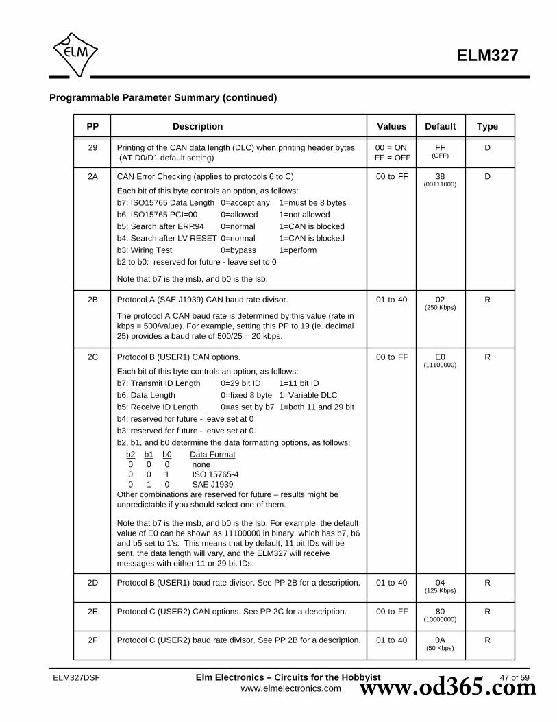
47 of 59ELM327DSF Elm Electronics – Circuits for the Hobbyistwww.elmelectronics.com
ELM327
Programmable Parameter Summary (continued)
29 Printing of the CAN data length (DLC) when printing header bytes (AT D0/D1 default setting)
DFF(OFF)
PP Description Values Default Type
2C Protocol B (USER1) CAN options.
2D
2E 80(10000000)
2F 0A(50 Kbps)
Protocol B (USER1) baud rate divisor. See PP 2B for a description.
00 to FF
E0(11100000)
04(125 Kbps)
01 to 40
00 to FF
Protocol C (USER2) CAN options. See PP 2C for a description.
Protocol C (USER2) baud rate divisor. See PP 2B for a description.
01 to 40
R
Each bit of this byte controls an option, as follows:b7: Transmit ID Length 0=29 bit ID 1=11 bit IDb6: Data Length 0=fixed 8 byte 1=Variable DLCb5: Receive ID Length 0=as set by b7 1=both 11 and 29 bit b4: reserved for future - leave set at 0b3: reserved for future - leave set at 0.b2, b1, and b0 determine the data formatting options, as follows: b2 b1 b0 Data Format 0 0 0 none 0 0 1 ISO 15765-4 0 1 0 SAE J1939Other combinations are reserved for future – results might be unpredictable if you should select one of them.
R
R
R
2B Protocol A (SAE J1939) CAN baud rate divisor. 02(250 Kbps)
01 to 40
The protocol A CAN baud rate is determined by this value (rate in kbps = 500/value). For example, setting this PP to 19 (ie. decimal 25) provides a baud rate of 500/25 = 20 kbps.
R
00 = ONFF = OFF
2A CAN Error Checking (applies to protocols 6 to C) 38(00111000)
00 to FF D
Each bit of this byte controls an option, as follows:b7: ISO15765 Data Length 0=accept any 1=must be 8 bytesb6: ISO15765 PCI=00 0=allowed 1=not allowedb5: Search after ERR94 0=normal 1=CAN is blockedb4: Search after LV RESET 0=normal 1=CAN is blockedb3: Wiring Test 0=bypass 1=performb2 to b0: reserved for future - leave set to 0
Note that b7 is the msb, and b0 is the lsb.
Note that b7 is the msb, and b0 is the lsb. For example, the default value of E0 can be shown as 11100000 in binary, which has b7, b6 and b5 set to 1’s. This means that by default, 11 bit IDs will be sent, the data length will vary, and the ELM327 will receive messages with either 11 or 29 bit IDs.
www.od365.com

48 of 59ELM327DSF Elm Electronics – Circuits for the Hobbyistwww.elmelectronics.com
ELM327
Using Higher RS232 Baud Rates
The RS232 serial interface has been maintainedthroughout the ELM OBD products, largely due to itsversatility. Older computers and PDAs can use itdirectly, as can microprocessors. Newer computersgenerally do not have physical RS232 ports, but theydo have USB and ethernet ports, both of which can beconverted to RS232 with a simple adapter.
Most people will build their ELM327 circuits withan RS232 interface, mainly because it is relativelyeasy and inexpensive to do. A circuit such as the oneshown in Figure 9 requires very few components andworks extremely well at speeds of up to 57600 bps.Depending on your computer’s RS232 voltages, yourwiring practices, and your choice of components, itmay also work well at speeds as high as 115200 bps.This is the approximate limit of such a circuit however,and anything operating at this speed should bethoroughly tested.
Users that would like to operate at speeds in therange of 115200 bps (or higher) may wish to look atsome of the single IC solutions that are available.These include devices such as the ADM232A fromAnalog Devices (http://www.analog.com/), or thepopular MAX232 series of ICs from Maxim IntegratedProducts (http://www.maxim-ic.com/). These are allexcellent devices that can be used for speeds of up to115.2 Kbps. We do caution that many of these types ofdevices are only rated for operation up to 120 Kbps,however, so may not be suitable for higher data rates -be sure to check the manufacturers data sheet beforecommitting to a design.
An RS232 interface needs relatively large voltageswings, which are difficult to maintain at higher rateswith large cable capacitances to contend with. (Atypical interface is often limited to about 230.4Kbpsunder ideal conditions.) If you need to operate theELM327 at these speeds or higher, it is recommendedthat you consider alternatives.
One popular alternative is a USB data connection.The USB interface is capable of very high data transferrates, certainly much higher than the 500 Kbps limit ofthe ELM327. Several manufacturers offer special‘bridge’ circuits that simplify connecting an RS232device (such as the ELM327) directly to the USB bus.Examples are the CP2102 from Silicon Labs(http://www.silabs.com/) or the FT232R from FutureTechnology Devices (http://www.ftdichip.com/). Ifplanning to use the higher baud rates (ie up to 500Kbaud), these interfaces are essential.
We are often asked if it is possible to use a direct
connection to a microprocessor. That is certainly anoption, and one that allows a full speed connection atessentially zero cost. If you are developing such aninterface, refer to page 51 for more details.
The default configuration for the ELM327 providesan RS232 data rate of either 9600 baud, or 38400baud, depending on the voltage level at pin 6 duringpower up or reset. While the 9600 baud rate is notadjustable, the 38400 one is (beginning with v1.2 ofthe IC). There are two ways that the rate can bechanged – either permanently with a ProgrammableParameter, or temporarily with an AT command.
Programmable Parameter ‘0C’ is the memorylocation that allows you to store a new baud rate whichreplaces the 38.4Kbps high speed rate. The value isstored in ‘non-volatile’ memory (EEPROM) that is notaffected by power cycles or resets (but changing thisvalue may affect the operation of some softwarepackages, so be careful how you use it).
If you store a new value in PP 0C, then enable it,and if pin 6 is at a high level during the next powerup,then your stored rate will become the new default datarate. (If it has not been enabled, the rate will revert tothe factory default of 38.4Kbps.) As an example,perhaps you would like to have the ELM327 use abaud rate of 57.6Kbps, rather than the factory settingof 38.4Kbps. To do this, determine the required valuefor PP 0C, store this value in PP 0C, and then enablethe PP.
The value stored in PP 0C is actually an internaldivisor that is used to determine the baud rate (it willbe 4000Kbps divided by the value of PP 0C). Toobtain a setting of 57.6, a baud rate divisor of 69 isrequired (4000/69 is approximately 57.6). Since 69 indecimal is 45 in hexadecimal, you need to tell theELM327 to set the value of PP 0C to 45, with thiscommand:
>AT PP 0C SV 45
then enable the new value for use:
>AT PP 0C ON
from that point (until PP 0C is turned off), the defaultdata rate will be 57.6K, and not 38.4K. Note that thevalue that you write does not become effective untilthe next full reset (a power off/on, AT Z, or MCLRpulse).
If you are designing your own circuitry, you willknow what your circuit is capable of, and can assign avalue to PP 0C. Software developers will not usually
www.od365.com
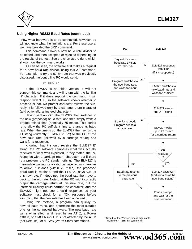
49 of 59ELM327DSF Elm Electronics – Circuits for the Hobbyistwww.elmelectronics.com
ELM327
Using Higher RS232 Baud Rates (continued)
* Note that the 75msec time is adjustable (with the AT BRT hh command)
know what hardware is to be connected, however, sowill not know what the limitations are. For these users,we have provided the BRD command.
This command allows a new baud rate divisor tobe tested, and then accepted or rejected depending onthe results of the test. See the chart at the right, whichshows how the command works.
As can be seen, the software first makes a requestfor a new baud rate divisor, using this AT command.For example, to try the 57.6K rate that was previouslydiscussed, the controlling PC would send:
AT BRD 45
If the ELM327 is an older version, it will notsupport this command, and will return with the familiar‘?’ character. If it does support the command, it willrespond with ‘OK’, so the software knows whether toproceed or not. No prompt character follows the ‘OK’reply; it is followed only by a carriage return character(and optionally, a linefeed character).
Having sent an ‘OK’, the ELM327 then switches tothe new (proposed) baud rate, and then simply waits apredetermined time (nominally 75 msec). This periodis to allow the PC sufficient time to change its baudrate. When the time is up, the ELM327 then sends theID string (currently ‘ELM327 v1.3a’) to the PC at thenew baud rate (followed by a carriage return) andwaits for a response.
Knowing that it should receive the ELM327 IDstring, the PC software compares what was actuallyreceived to what was expected. If they match, the PCresponds with a carriage return character, but if thereis a problem, the PC sends nothing. The ELM327 ismeanwhile waiting for a valid carriage return characterto arrive. If it does (within 75 msec), the proposedbaud rate is retained, and the ELM327 says ‘OK’ atthis new rate. If it does not, the baud rate then revertsback to the old rate. Note that the PC might correctlyoutput the carriage return at this new rate, but theinterface circuitry could corrupt the character, and theELM327 might not see a valid response, so yoursoftware must check for an ‘OK’ response beforeassuming that the new rate has been accepted.
Using this method, a program can quickly tryseveral baud rates, and determine the most suitableone for the connected hardware. The new baud ratewill stay in effect until reset by an AT Z, a PowerOff/On, or a MCLR input. It is not affected by the AT D(set Defaults), or AT WS (Warm Start) commands.
Request for a newbaud rate divisor:AT BRD hh ELM327 responds
with ‘OK’(if it is supported)
ELM327 sendsthe AT I string
Program switches tothe new baud rate,and waits for input
ELM327 waitsup to 75 msec*
for a carriage return
If the Rx is good,Program sends acarriage return
ELM327 says ‘OK’(and remains at thenew baud setting)
Baud rate revertsto the previous
baud rate
PC ELM327
CRreceived
?
yesno
Print a prompt,and wait for thenext command
ELM327 switches tonew baud rate andwaits for 75msec*
www.od365.com

50 of 59ELM327DSF Elm Electronics – Circuits for the Hobbyistwww.elmelectronics.com
ELM327
Setting Timeouts - AT ST and AT AT Commands
Users often ask about how to obtain faster OBDscanning rates. There is no definite answer for allvehicles, but the following information may help withunderstanding how the settings might apply to yourvehicle.
A typical vehicle request and response is shown inthe diagram below:
The ELM327 sends a request then waits up to200msec for a reply. If none were to come, an internaltimer would stop the waiting, and the ELM327 wouldprint “NO DATA”.
After each reply has been received, the ELM327must wait to see if any more replies are coming (and ituses the same internal timer to stop the waiting if nomore replies arrive). With our initial OBD products (theELM320, ELM322 and ELM323) we found that oldervehicles often needed a timeout setting of about 100msec, and occasionally they needed more, so wesettled on a standard default setting of 200 msec.
If a typical vehicle query response time were about50 msec, and the timeout were set to 200 msec, thefastest scan rate possible would only be about 4queries per second. Changing the ST time to about100msec would almost double that rate, giving about 7queries per second. Clearly, if you were to know howlong it takes for your vehicle to reply, you might beable to improve on the scan rate, by adjusting the STtime.
It is not easy to tell how fast a vehicle replies torequests. For one thing, requests all have prioritiesassigned, so responses may be fast at some times,and slower at others. The physical measurement ofthe time is not easy either - it requires expensive testequipment just to make one measurement. To helpwith this, we added a new feature to the v1.2 IC, calledAdaptive Timing.
Adaptive timing actually makes the response timemeasurements for you, and adjusts the AT ST time to
a value that should work for most situations. It isenabled by default, but can be disabled with the AT0command should you not agree with what it is doing(there is also an AT2 setting that is a little moreagressive, should you wish to experiement). For 99%of all vehicles, we recommend that you simply leavethe settings at their default values, and let the ELM327make the adjustments for you.
Surely there has to be a way to eliminate that finaltimeout, if you know how many responses to expect?There is a way now, with v1.3a of the ELM327.
Consider the following times taken from a J1850VPW vehicle, in response to an 01 00 request:
The engine responds very quickly, but thetransmission takes considerably longer. The adaptivetiming algorithm measures the longer transmissionresponse times and will use them to set the timeout,likely to a value in the range of 90msec. With atimeout of 90 msec, the maximum scan rate may beabout 6 readings per second.
Instead of sending 01 00 for the above request,the ELM327 will now also accept 01 00 2. This tellsthe IC to send 01 00, then return immediately afterreceiving 2 responses. It can not speed up a slowECU, but it will eliminate the final delay, as theELM327 now knows the number of responses toexpect.
We do caution that you use this new featurecarefully. If you set the last digit to a number that isless than the actual number of responses, thenacknowledgements that may be required will not besent, and some protocols may begin resending themessage, looking for a response. This will lead tounnecessary network congestion, and should beavoided. Before using this feature, always determinethe number of responses that will be coming from thevehicle, and then set the responses digit to that value.
ELM327
Vehicle
58 msec
engine(ECU 10)
transmission(ECU 18)
4 msec
ELM327
Vehicle
request is sent
response
ELM waitsup to 200msec
ELM waits 200msecfor more responses
www.od365.com

1 2 3 4 5 6 7 8 9 10 11 12 13 14
1516171819202122232425262728
A very common question that we receive is “Can Iconnect the ELM327 directly to my own circuit, or mustI use the RS232 interface shown?” Certainly you mayconnect directly to our ICs, and you do not need to usean RS232 interface. There are a few items to consider,however.
The ELM327 is actually a microprocessor thatcontains a standard UART type interface, connected tothe RS232 Tx and Rx pins. The logic type is CMOS,and this is compatible with virtually all 5V TTL andCMOS circuits, so you should be able to connectdirectly to these pins provided that the two devicesshare the same power supply (5V), and that they arenot physically more than about 10 to 20 inches apart(CMOS circuits are subject to latchup from inducedcurrents, which may be a problem if you have longleads).
The normal (idle) levels of the ELM327 transmitand receive pins are at the VDD (5V) level. Mostmicroprocessors and RS232 interface ICs expect thatto be the idle level, but you should verify it for yourmicroprocessor before connecting to the ELM327. Theconnections are straightforward - transmit connects toreceive, and receive connects to transmit, as shownbelow. Don’t forget to set both devices to the samebaud rate.
The ELM327 also provides a hand-shaking featurethat may simplify the flow of data for you. The interface
consists of two pins - an input an an output. The inputis called “request to send” (RTS), and it is used tointerrupt the ELM327, just the same as tapping a keyon the keyboard when using a terminal program. Theoutput pin (“Busy”) is used by the ELM327 to tell yoursystem that it is processing data.
To use the handshaking feature, set one of yourport pins to normally provide a high output, andconnect it to the RTS input (pin 15). Use another portpin as an input to monitor the ELM327 Busy output.When you want to send a command, simply check theBusy output first. If it is at a high logic level, then eitherwait for it to go low, or if you need to interrupt the IC,then bring the RTS line low and wait for the Busy lineto go low. (You might want to consider using an edgetriggered interrupt on the Busy output, if one isavailable). When Busy does go low, restore your RTSline to a high level, and then send your command tothe ELM327. No need to worry about the ELM327becoming busy again after you raise the RTS line atthis point – once Busy goes low, the ELM327 will wait(indefinitely) for your command.
If you do not use the RTS input on the ELM327, itmust be connected to a high logic level, as shownbelow.
Microprocessor Interfaces
51 of 59ELM327DSF Elm Electronics – Circuits for the Hobbyistwww.elmelectronics.com
ELM327
+5V
X14.00MHz
C427pF
R27-30470Ω
+5V
C327pF
+5V
+5V
toR15to
R21
n.c.
+5V
327
L1-L4
your microprocessorTx Rx
TxRxThe ELM327 and yourmicroprocessor mustuse the same 5V supply
Busy RTS
www.od365.com

Error Messages
?
This is the standard response for a misunderstoodcommand received on the RS232 input. Usually it isdue to a typing mistake.
BUFFER FULL
The ELM327 provides a 256 byte internal RS232transmit buffer so that OBD messages can be receivedquickly, stored, and sent to the computer or PDA at amore constant rate. Occasionally (particularly withCAN systems) the buffer will fill at a faster rate than itis being ‘emptied.’ Eventually it may become full, andno more data can be stored (it is lost).
If you are receiving BUFFER FULL messages,and are using a 9600 baud data rate, give seriousconsideration to changing your data rate to 38400baud. If you still receive BUFFER FULL messagesafter that, consider some of the filtering options (theMR, MT, CF and CM AT Commands).
BUS BUSY
The ELM327 tried to send the message, or tried toinitialize the bus, and detected too much activity to doso (it needs a pause in activity in order to insert themessage). Although this could be because the buswas in fact very busy, it is most often due a wiringproblem that is giving a continuously active input. Ifthis is an initial trial with your ELM327 circuit, check allof the voltage levels at the offending OBD input – thiserror is very likely due to a wiring problem.
BUS ERROR
A generic problem has occured. This is most oftenfrom an invalid signal being detected (a pulse that islonger than a Break signal, etc.) on the bus, but couldbe from a wiring error. Note that some vehicles maygenerate long pulses as part of their startup process,so you may see this message as part of a normalvehicle startup while ‘monitoring all.’
CAN ERROR
The CAN system had difficulty initializing, sending,or receiving. Often this is simply from not beingconnected to a CAN system when you attempt to senda message, but it may be because you have set thesystem to an incorrect protocol, or to a rate that doesnot match the actual data rate. As with BUS ERRORs,the CAN ERROR might also be the result of a wiringproblem, so if this is the first time using your ELM327circuit, review all of your CAN interface circuitry beforeproceeding.
DATA ERROR
There was a response from the vehicle, but theinformation was incorrect or could not be recovered.
<DATA ERROR
There was an error in the line that this points to,either from an incorrect checksum, or a problem withthe format of the message (the ELM327 still showsyou what it received). There could have been a noiseburst which interfered, possibly a circuit problem, orperhaps you have the CAN Auto Formatting (CAF) onand you are looking at a system that is not of theISO 15765-4 format. Try re-sending the commandagain – if it was a noise burst, it may be receivedcorrectly the second time.
ERRxx
There are a number of internal errors that might bereported as ERR with a two digit code following. Theseoccur if an internally monitored parameter is found tobe out of limits, or if a module is not respondingcorrectly. If you witness one of these, contact ElmElectronics for advice.
One error that is not necessarily a result of aninternal problem is ERR94. This code represents a‘fatal CAN error’, and may be seen if there are CANnetwork issues (some non-CAN vehicles may use pins
When hardware or data problems occur, theELM327 will respond with one of the following shortmessages. Some of the messages are suppressedduring an automatic search for a protocol, and are onlyvisible if not in the ‘auto’ mode.
Here is a brief description of each:
ELM327
52 of 59ELM327DSF Elm Electronics – Circuits for the Hobbyistwww.elmelectronics.com www.od365.com

53 of 59ELM327DSF Elm Electronics – Circuits for the Hobbyistwww.elmelectronics.com
ELM327
6 and 14 of the connector for other functions, and thismay cause problems). If you see an ERR94, it meansthat the CAN module was not able to reset itself, andneeded a complete IC reset to do so. You will need torestore any settings that you had previuosly made, asthey will have been restored to their default values.
Beginning with v1.3a of this IC, an ERR94 will alsoblock any automatic searches through the CANprotocols, if bit 5 of PP 2A is a ‘1’ (it is by default). Thisis done because most ERR94s will be as a result ofserious CAN wiring problems. Blocking of the CANprotocols remains in effect until the next power off andon, or until an AT FE is sent.
FB ERROR
When an OBD output is energized, a check isalways made to ensure that the signal also appears atthe respective input. If there is a problem, and noactive input is detected, the IC turns the output off anddeclares that there was a problem with the FeedBack(FB) of the signal. If this is an initial trial with yourELM327, this is almost certainly a wiring problem.Check your wiring before proceeding.
LV RESET
The ELM327 continually monitors the 5V supply toensure that it is within acceptable limits. If the voltageshould go below the low limit, a ‘brownout reset’ circuitis activated, the IC stops all activity, performs a fullreset, and then prints LV RESET. Note that this type ofreset is exactly the same as an AT Z or MCLR reset(but it does not print ELM327 v1.3a).
Beginning with v1.3a of this IC, an LV RESET willalso block any automatic searches through the CANprotocols, if bit 4 of PP 2A is a ‘1’ (it is by default). Thisis done because most LV RESETs will be as a resultof CAN wiring problems, if they should start occurringsuddenly. Blocking of the CAN protocols is only doneuntil the next reset (AT Z, WS, etc.) or until an AT FEis sent.
NO DATA
The IC waited for the period of time that was setby AT ST, and detected no response from the vehicle.It may be that the vehicle had no data to offer for thatparticular PID, that the mode requested was notsupported, that the vehicle was attending to higherpriority issues, or in the case of the CAN systems, the
Error Messages (continued)
filter may have been set so that the response wasignored, even though one was sent. If you are certainthat there should have been a response, try increasingthe ST time (to be sure that you have allowed enoughtime for the ECU to respond), or restoring the CANfilter to its default setting.
<RX ERROR
An error was detected in the received CAN data.This will usually only occur if monitoring a CAN bus,with an incorrect baud rate setting, or if monitoring andthere are messages found that are not beingacknowledged, or that contain bit errors. The entiremessage will be displayed as it was received (if youhave filters set, the received mesage may not agreewith the filter setting). Try a different protocol, or adifferent baud rate.
STOPPED
If a protocol initiation or search should beinterrupted by a received RS232 character or a lowlevel on the RTS pin, the ELM327 will print the wordSTOPPED, to show why it is aborting the OBDcommand, and returning to the prompt state. If youshould see this response, then something hasinterrupted the process that was in progress.
UNABLE TO CONNECT
The ELM327 has tried all of the availableprotocols, and could not detect a compatible one. Thiscould be because your vehicle uses an unsupportedprotocol, or could be as simple as forgetting to turn theignition key on. Check all of your connections, and theignition, then try the command again.
www.od365.com
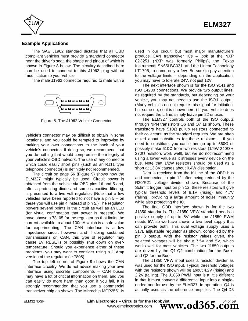
Figure 8. The J1962 Vehicle Connector
81
9 16
Example Applications
The SAE J1962 standard dictates that all OBDcompliant vehicles must provide a standard connectornear the driver’s seat, the shape and pinout of which isshown in Figure 8 below. The circuitry described herecan be used to connect to this J1962 plug withoutmodification to your vehicle.
The male J1962 connector required to mate with a
vehicle’s connector may be difficult to obtain in somelocations, and you could be tempted to improvise bymaking your own connections to the back of yourvehicle’s connector. If doing so, we recommend thatyou do nothing that would compromise the integrity ofyour vehicle’s OBD network. The use of any connectorwhich could easily short pins (such as an RJ11 typetelephone connector) is definitely not recommended.
The circuit on page 56 (Figure 9) shows how theELM327 might typically be used. Circuit power isobtained from the vehicle via OBD pins 16 and 5 and,after a protecting diode and some capacitive filtering,is presented to a five volt regulator. (Note that a fewvehicles have been reported to not have a pin 5 – onthese you will use pin 4 instead of pin 5.) The regulatorpowers several points in the circuit as well as an LED(for visual confirmation that power is present). Wehave shown a 78L05 for the regulator as that limits thecurrent available to about 100mA which is a safe valuefor experimenting. The CAN interface is a lowimpedance circuit however, and if doing sustainedtransmissions on CAN, this type of regulator maycause LV RESETs or possibly shut down on over-temperature. Should you experience either of theseproblems, you may want to consider using a 1 Ampversion of the regulator (ie 7805).
The top left corner of Figure 9 shows the CANinterface circuitry. We do not advise making your owninterface using discrete components – CAN busesmay have a lot of critical information on them, and youcan easily do more harm than good if you fail. It isstrongly recommended that you use a commercialtransceiver chip as shown. The Microchip MCP2551 is
used in our circuit, but most major manufacturersproduce CAN transceiver ICs – look at the NXP82C251 (NXP was formerly Philips), the TexasInstruments SN65LBC031, and the Linear TechnologyLT1796, to name only a few. Be sure to pay attentionto the voltage limits – depending on the application,you may have to tolerate 24V, not just 12V.
The next interface shown is for the ISO 9141 andISO 14230 connections. We provide two output lines,as required by the standards, but depending on yourvehicle, you may not need to use the ISO-L output.(Many vehicles do not require this signal for initiation,but some do, so it is shown here.) If your vehicle doesnot require the L line, simply leave pin 22 unused.
The ELM327 controls both of the ISO outputsthrough NPN transistors Q6 and Q7 as shown. Thesetransistors have 510Ω pullup resistors connected totheir collectors, as the standard requires. We are oftenasked about substitutes for these resistors – if youneed to substitute, you can either go up to 560Ω orpossibly make 510Ω from two resistors (1/4W 240Ω +270Ω resistors work well), but we do not recommendusing a lower value as it stresses every device on thebus. Note that 1/2W resistors should be used as ashort at 13.8V causes about 0.4W dissipation.
Data is received from the K Line of the OBD busand connected to pin 12 after being reduced by theR20/R21 voltage divider shown. Because of theSchmitt trigger input on pin 12, these resistors will givetypical threshold levels of 9.1V (rising) and 4.7V(falling), providing a large amount of noise immunitywhile also protecting the IC.
The final OBD interface shown is for the twoJ1850 standards. The J1850 VPW standard needs apositive supply of up to 8V while the J1850 PWMneeds 5V, so we have shown a two level supply thatcan provide both. This dual voltage supply uses a317L adjustable regulator as shown, controlled by thepin 3 output. With the resistor values given, theselected voltages will be about 7.5V and 5V, whichworks well for most vehicles. The two J1850 outputsare driven by the Q1-Q2 combination for the Bus+,and Q3 for the Bus-.
The J1850 VPW input uses a resistor divider aswas used for the ISO input. Typical threshold voltageswith the resistors shown will be about 4.2V (rising) and2.2V (falling). The J1850 PWM input is a little differentin that it must convert a differential input into a single-ended one for use by the ELM327. In operation, Q4 isactually used as the difference amplifier. The Q4-D3
ELM327
54 of 59ELM327DSF Elm Electronics – Circuits for the Hobbyistwww.elmelectronics.com www.od365.com

ELM327
ELM327DSF Elm Electronics – Circuits for the Hobbyistwww.elmelectronics.com
series circuit sets a threshold voltage of about 1V (fornoise immunity), while R11 limits the current flow, andR12 keeps Q4 off when the input is left open-circuited.
Resistor R36 has been added to the circuit ofFigure 9, to help turn transistor Q4 off more rapidly incertain circumstances. The resistor is generally notrequired, but it may be helpful if you are connected toa very high capacitance J1850 VPW system then forcethe ELM327 to operate in the J1850 PWM mode, andexperience some false BUS ERRORs. We show theresistor as an option and leave the choice whether toinstall it up to you.
The voltage monitoring circuitry for the AT RVcommand is shown in this schematic connected to pin2 of the ELM327. The two resistors simply divide thebattery voltage to a safe level for the ELM327, and thecapacitor filters out noise. As shipped, the ELM327expects a resistor divider ratio as shown, and setsnominal calibration constants assuming that. If yourapplication needs a different range of values, simplychoose the resistor values to maintain the input withinthe specified 0-5V limit, and then perform an AT CV tocalibrate the ELM327 to your new divider ratio. Themaximum voltage that the ELM327 can show is 99.9V.
A very basic RS232 interface is shown connectedto pins 17 and 18 of the ELM327. This circuit ‘steals’power from the host computer in order to provide a fullswing of the RS232 voltages without the need for anegative supply. The RS232 pin connections shownare for a standard 9 pin connector. If you are using a25 pin one, you will need to compensate for thedifferences. The polarity of the ELM327’s RS232 pinsis such that they are compatible with standardinterface ICs (MAX232, etc.), so if you should prefersuch an interface, you can remove all of the discretecomponents shown and use one of those.
The four LEDs shown (on pins 25 to 28) havebeen provided as a visual means of confirming circuitactivity. They are not essential, but it is nice to see thevisual feedback when experimenting.
Finally, the crystal shown connected between pins9 and 10 is a standard 4.000MHz microprocessor typecrystal. The 27pF crystal loading capacitors shown aretypical only, and you may have to select other valuesdepending on what is specified for the crystal youobtain. The crystal frequency is critical to circuitoperation and must not be altered.
We often receive requests for parts lists toaccompany our Example Applications circuits. Sincethis circuit is more complex than most, we have
named/numbered all of the components and provideda summary parts list (see Figure 10). Note that theseare only suggestions for parts. If you prefer anotherLED colour, or have a different general purposetransistor on hand, etc., by all means make thechange. A quick tip for those having trouble finding a0.3” wide socket for the ELM327: many of the standard14 pin sockets can be placed end-to-end to form one0.3” wide 28 pin socket.
What if you only want to use one of the protocols?What if you want to use a USB interface? These arecommon questions that we receive, and both areaddressed in Figure 11.
There are a few single IC products on the marketthat allow you to connect an RS232 system directly toUSB. We have shown the CP2102 by SiliconLaboratories (http://www.silabs.com) in Figure 11, butthere are others available as well – Future TechnologyDevices (http://www.ftdichip.com), for example,produces several. These ICs provide a very simpleand relatively inexpensive way to ‘bridge’ betweenRS232 and USB, and as you can see, require very fewcomponents to support them.
If using the CP2102, we do caution that it is verysmall and difficult to solder by hand, so be preparedfor that. Also, if you provide protection on the datalines with transient voltage suppressors (TVS’s), becareful of which ones you choose, as some exhibit avery large capacitance and will affect the transmissionof the USB data. Note also that the circuit aspresented will operate at a 38400 bits per second rate.If you want to take full advantage of the speed of theUSB interface, you will need to change PP 0C.
Considering the OBD protocol portions of thecircuits in Figures 9 and 11, the differences should bevery apparent. The unused protocols in Figure 11 havesimply had their outputs ignored (left open circuit), andtheir inputs wired to a convenient logic level (as CMOSinputs must never be left floating).
The circuit maintains the status LEDs, and theJ1850 Bus+ circuitry, but the majority of the rest hasbeen eliminated. The voltage switching circuitry hasbeen reduced to a single 8V regulator as well, sincethere will be no need to switch to 5V. Note that pin 3has been intentionally left open-circuited as it is notrequired by the voltage regulator.
The first time that this circuit is used, it will likely beset to protocol 0, the default ‘automatic search’ modeof operation (as shipped from the factory). When youconnect it to the J1850 VPW vehicle, it will then
Example Applications (continued)
55 of 59www.od365.com
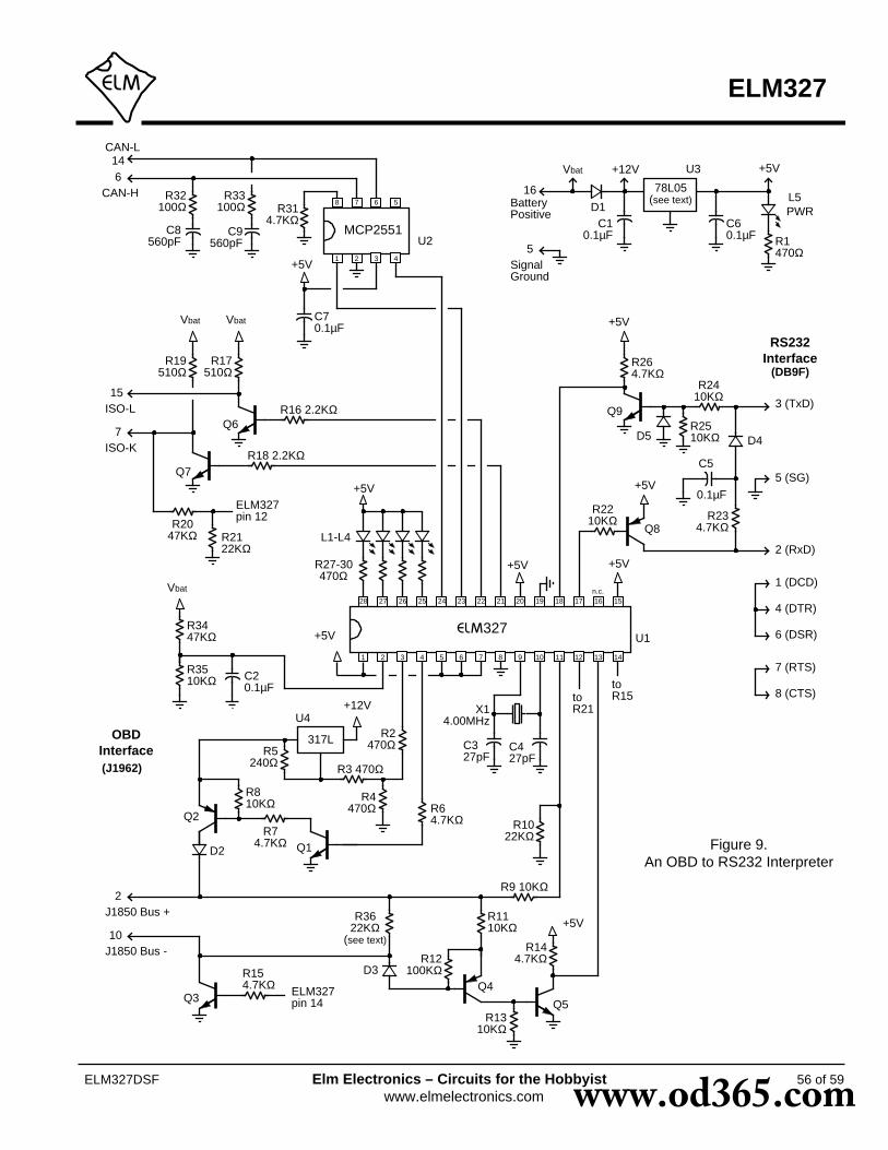
R3622KΩ
(see text)
56 of 59
ELM327
ELM327DSF Elm Electronics – Circuits for the Hobbyistwww.elmelectronics.com
Figure 9.An OBD to RS232 Interpreter
2 (RxD)
X14.00MHz
C427pF
RS232Interface
(DB9F)
OBDInterface
R27-30470Ω
+5V
C327pF
+5V
+5V
+5V
3 (TxD)
5 (SG)
1 (DCD)
4 (DTR)
6 (DSR)
7 (RTS)
8 (CTS)
+5V
317L
+12V
ELM327pin 14
R154.7KΩ
toR15
+5V
(J1962)
J1850 Bus +2
J1850 Bus -10
Q5
toR21
n.c.
+5V
+5V
CAN-H6
CAN-L14
1 2 3 4
5678
MCP2551PWR
Vbat Vbat
ISO-L15
ISO-K7
ELM327pin 12
Vbat
327
1 2 3 4 5 6 7 8 9 10 11 12 13 14
1516171819202122232425262728
U1
BatteryPositive
16 78L05(see text)
Vbat +12V
SignalGround
5
+5V
R1470Ω
C60.1µF
C10.1µF
D1
R264.7KΩ
R2410KΩ
R2510KΩ D4D5
C5
0.1µF
R234.7KΩ
R2210KΩ
Q8
Q9
L1-L4
L5R32100Ω
R33100Ω
C8560pF
C9560pF
R314.7KΩ
C70.1µF
R19510Ω
R17510Ω
R16 2.2KΩ
R18 2.2KΩ
R2047KΩ R21
22KΩ
R3447KΩ
R3510KΩ C2
0.1µF
R5240Ω R3 470Ω
R4470Ω
R2470Ω
R810KΩ
R74.7KΩ Q1
Q2R64.7KΩ R10
22KΩ
R9 10KΩ
R1110KΩ
R12100KΩD3
Q4
R1310KΩ
R144.7KΩ
Q3
D2
Q6
Q7
U2
U3
U4
www.od365.com

57 of 59
ELM327
ELM327DSF Elm Electronics – Circuits for the Hobbyistwww.elmelectronics.com
ResistorsR32, R33= 100 ΩR5 = 240 ΩR1, R2, R3, R4, R27, R28, R29, R30 = 470 ΩR17, R19 = 510 Ω 1/2WR16, R18 = 2.2 KΩR6, R7, R14, R15, R23, R26, R31 = 4.7 KΩR8, R9, R11, R13, R22, R24, R25, R35 = 10 KΩR10, R21, R36 = 22 KΩR20, R34 = 47 KΩR12 = 100 KΩ
MiscX1 = 4.000MHz crystalRS232 Conn = DB9FIC Socket = 28pin 0.3” (or 2 x 14pin)
SemiconductorsD1 = 1N4001D2, D3, D4, D5 = 1N4148L1, L2, L3, L4 = Yellow LEDL5 = Green LEDQ1, Q3, Q5, Q6, Q7, Q9 = 2N3904 (NPN)Q2, Q4, Q8 = 2N3906 (PNP)U1 = ELM327U2 = MCP2551U3 = 78L05 (5V, 100mA regulator)U4 = 317L (adj. 100mA regulator)
CapacitorsC1, C2, C5, C6, C7 = 0.1uF 16VC3, C4 = 27pFC8, C9 = 560pF
Figure 10. Parts List for Figure 9
Example Applications (continued)
automatically detect the protocol, and if the memory isenabled (as shown), J1850 VPW will then become thenew default, with no input required by you. This willwork well for most applications, but if the circuit is usedon a vehicle with the key off, for example, then it willagain go searching for a new protocol. In general, youdo not want this to happen every time. It may be only aminor inconvenience to have to wait while the ELM327determines that it is “UNABLE TO CONNECT”, butwhy go through it if you do not have to? If you knowthat you are using the circuit in a J1850 VPW onlyapplication (protocol 2) then you should issue thecommand AT SP 2 the very first time that the circuit ispowered. From that point on, it will remain in protocol2, whether it fails to make a connection or not.
Depending on the circumstances, you may be ableto simplify this circuit even further, by possibly usingthe USB connection to obtain 5V for the ELM327,rather than the 78L05 regulator shown. We cautionthat some protocols (CAN for example), may drawmore current than your USB connection is able to
supply, so review this first.This has provided two examples of how the
ELM327 integrated circuit might be used. Hopefully ithas been enough to get you started on your way tomany more… we hope that you enjoy the journey!
www.od365.com

Example Applications (continued)
58 of 59
ELM327
ELM327DSF Elm Electronics – Circuits for the Hobbyistwww.elmelectronics.com
Figure 11. An OBD (J1850 VPW) to USB Interpreter
2 (D-)
4.00MHz
27pF
USBInterface(type ‘B’
connector)
OBDInterface
4 x470Ω
+5V
27pF
+5V
+5V
1 (+5)
4 (SG)+5V
78L08
+12V
(J1962)
J1850 Bus +2
1 2 3 4 5 6 7 8 9 10 11 12 13 14
1516171819202122232425262728
10KΩ
4.7KΩ
4.7KΩ22KΩ
10KΩ
PWRBatteryPositive
16 78L05
+12V
SignalGround
5
+5V
470Ω0.1µF0.1µF
+5V
3 (D+)
SiLabsCP2102
0.1µF
5.0VTVS
1µF
7
6
26 253
4
5
8
+5V
327
www.od365.com

Section Index
Description and Features....................................................................................... 1
Pin Descriptions..................................................................................................... 2
Ordering Information.............................................................................................. 3
Absolute Maximum Ratings....................................................................................4
Electrical Characteristics........................................................................................ 4
Overview................................................................................................................ 5
Communicating with the ELM327...........................................................................5
AT Commands....................................................................................................... 7
AT Command Summary.........................................................................................7
AT Command Descriptions.................................................................................... 9
Reading the Battery Voltage................................................................................ 22
OBD Commands.................................................................................................. 23
Talking to the Vehicle........................................................................................... 24
Interpreting Trouble Codes...................................................................................26
Resetting Trouble Codes......................................................................................27
Quick Guide for Reading Trouble Codes............................................................. 27
Bus Initiation.........................................................................................................28
Wakeup Messages...............................................................................................28
Selecting Protocols...............................................................................................29
OBD Message Formats........................................................................................30
Setting the Headers..............................................................................................32
Monitoring the Bus............................................................................................... 35
CAN Messages and Filtering................................................................................36
Multiline Responses............................................................................................. 37
CAN Message Formats........................................................................................ 39
Altering Flow Control Messages...........................................................................40
J1939 Support...................................................................................................... 41
Restoring Order....................................................................................................43
Programmable Parameters.................................................................................. 44
Programmable Parameter Summary....................................................................45
Using Higher RS232 Baud Rates.........................................................................48
Setting Timeouts - AT ST and AT AT Commands............................................... 50
Microprocessor Interfaces.................................................................................... 51
Error Messages.................................................................................................... 52
Example Applications........................................................................................... 54
59 of 59
ELM327
ELM327DSF Elm Electronics – Circuits for the Hobbyistwww.elmelectronics.com www.od365.com