ELITE High Capacity Coriolis Flow and Density …€¦ · Micro Motion® ELITE® High Capacity...
24
Micro Motion ® ELITE ® High Capacity Coriolis Meters offer unparalleled flow and density measurement performance in a large size meter. Best precision flow and density measurement in a meter that fits large line sizes • Unique design delivers unparalleled measurement sensitivity and stability • Guarantees consistent, reliable performance over the widest flow range • Smart Meter Verification for quick, complete meter diagnosis without process interruption Superior performance in the most challenging applications • Available in Super Duplex for corrosive or high-pressure applications, ideal for oil production sites with sweet crude and brine • Industry standard for custody transfer and critical process control • Best two-phase flow capability for batching, loading, and entrained air applications • Immune to fluid, process, or environmental effects for superb mea- surement confidence Product Data Sheet PS-001042, Rev. G March 2011 Micro Motion ® ELITE ® High Capacity Coriolis Flow and Density Meters High performance compact drainable Coriolis meter Peak performance high capacity meter Hygienic compact drainable Coriolis meter Straight tube full-bore Coriolis meter General purpose flow-only Coriolis meter F-Series ELITE HC H-Series T-Series R-Series Extreme low- flow Coriolis meter LF-Series Peak performance Coriolis meter ELITE ®
Transcript of ELITE High Capacity Coriolis Flow and Density …€¦ · Micro Motion® ELITE® High Capacity...

Micro Motion® ELITE® High Capacity Coriolis Meters offer unparalleled flow and density measurement performance in a large size meter.
Best precision flow and density measurement in a meter that fits large line sizes
• Unique design delivers unparalleled measurement sensitivity and stability
• Guarantees consistent, reliable performance over the widest flow range
• Smart Meter Verification for quick, complete meter diagnosis without process interruption
Superior performance in the most challenging applications
• Available in Super Duplex for corrosive or high-pressure applications, ideal for oil production sites with sweet crude and brine
• Industry standard for custody transfer and critical process control
• Best two-phase flow capability for batching, loading, and entrained air applications
• Immune to fluid, process, or environmental effects for superb mea-surement confidence
Product Data SheetPS-001042, Rev. GMarch 2011
Micro Motion® ELITE® High Capacity Coriolis Flow and Density Meters
High performance compact drainable Coriolis meter
Peak performance high capacity meter
Hygienic compact drainable Coriolis meter
Straight tube full-bore Coriolis meter
General purpose flow-only Coriolis meter
F-Series
ELITE HC
H-Series
T-Series
R-Series
Extreme low-flow Coriolis meter
LF-Series
Peak performance Coriolis meter
ELITE®

2 ELITE® High Capacity Flow and Density Meters
Micro Motion ELITE High Capacity flow and density meters
Micro Motion Coriolis meters from Emerson Process Management meet a vast range of application needs, ranging from extreme low-flow up to high-flow, high-capacity lines. Cryogenic, hygienic, high-temperature, and high-pressure—Micro Motion meters can handle them all. Micro Motion meters are available with a variety of wetted parts to ensure the best material compatibility.
Coriolis meters. Coriolis meters offer dramatic benefits over traditional volumetric measurement technologies. Coriolis meters:
• Deliver accurate and repeatable process data over a wide range of flow rates and process conditions.
• Provide direct inline measurement of mass flow and density, and also measure volume flow and temperature—all from a single device.
• Have no moving parts, so maintenance costs are minimal.
• Have no requirements for flow conditioning or straight pipe runs, so installation is simplified and less expensive.
• Provide advanced diagnostic tools for both the meter and the process.
ELITE High Capacity Coriolis Meters. Micro Motion® ELITE® High Capacity Meters are the leading meters for precision flow and density measurement. ELITE meters offer the most accurate measurement available for virtually any process fluid, while exhibiting exceptionally low pressure drop.
ELITE High Capacity meters are available for:
• Standard applications (316L)
• High temperature applications (316L)
• High chloride applications (Super Duplex)
• High pressure applications (Super Duplex)
Now with Smart Meter Verification, Micro Motion ELITE meters deliver industry-best performance:
• Best measurement and ease of use for critical applications
• Best measurement performance for mass, density, and volume, regardless of process or environmental conditions
• Measurement capability for two-phase flow, liquid, and gas custody transfer
Contents
Liquid flow performance . . . . . . . . . . . . . . . . . . . 3
Gas flow performance . . . . . . . . . . . . . . . . . . . . . 3
Density performance (liquid only) . . . . . . . . . . . . 3
Environmental effects . . . . . . . . . . . . . . . . . . . . . 4
Temperature specifications . . . . . . . . . . . . . . . . . 5
Power consumption . . . . . . . . . . . . . . . . . . . . . . . 6
Pressure ratings . . . . . . . . . . . . . . . . . . . . . . . . . 6
Hazardous area classifications . . . . . . . . . . . . . . . 7
Materials of construction. . . . . . . . . . . . . . . . . . . . 9
Weight and center of gravity . . . . . . . . . . . . . . . . . 9
Dimensions. . . . . . . . . . . . . . . . . . . . . . . . . . . . . 10
Fitting options . . . . . . . . . . . . . . . . . . . . . . . . . . . 13
Ordering information. . . . . . . . . . . . . . . . . . . . . . 16

ELITE® High Capacity Flow and Density Meters 3
Liquid flow performance
Gas flow performance
Density performance (liquid only)
Mass Volume(1)
(1) Specifications for volumetric flow rate are based on a process-fluid density of 998,2 kg/m3. For fluids with density other than 1000 kg/m3, the volumetric flow rate equals the mass flow rate divided by the fluid’s density.
kg/h metric tons/h l/h m3/h
Maximum flow rate CMFHC2 1306000 1306 1306000 1306CMFHC3 2550000 2550 2550000 2550CMFHC4 3265870 3266 3265870 3266
Mass flow accuracy(2)
(2) Stated flow accuracy includes the combined effects of repeatability, linearity, and hysteresis. All specifications for liquids are based on reference conditions of water at 20 to 25 °C and 1 to 2 bar, unless otherwise noted.
±0,10% of rate(3)
(3) When flow rate is less than zero stability / 0,001, accuracy = ±[(zero stability / flow rate) × 100]% of rate, and repeatability = ±[½(zero stability / flow rate) × 100]%.
Volume flow accuracy(2) ±0,10% of rate(3)
Repeatability ±0,05% of rate(3)
kg/h
Zero stability CMFHC2 68CMFHC3 136CMFHC4 204
When selecting sensors for gas applications, measurement accuracy is a function of fluid mass flow rate independent of operating temperature, pressure, or composition. However, pressure drop through the sensor is dependent upon operating temperature, pressure, and fluid composition. Therefore, when selecting a sensor for any particular gas application, it is highly recommended that each sensor be sized using Micro Motion’s product selector, available at www.micromotion.com.
Accuracy(1)
(1) Accuracy includes the combined effects of repeatability, linearity, and hysteresis. Specifications are based on reference conditions of water at 20 to 25 °C and 1 to 2 bar, unless otherwise noted.
±0,5 kg/m3
Repeatability ±0,2 kg/m3
Range up to 5000 kg/m3

4 ELITE® High Capacity Flow and Density Meters
Environmental effects
Process temperature effect Process temperature effect is defined as:• For mass flow measurement, the worst-case zero offset due to process fluid
temperature change away from the zeroing temperature.• For density measurement, the maximum measurement offset due to process
fluid temperature change away from the density calibration temperature.
Process temperature effect
% of maximum flow rate per °C density accuracy per °C(1) (kg/m3)
(1) For –100 °C and above.
CMFHC2 ±0,00025 ±0,015
CMFHC3 ±0,00025 ±0,015
CMFHC4 ±0,00025 ±0,015
Pressure effect Pressure effect is defined as the change in sensor flow and density sensitivity due to process pressure change away from the calibration pressure. Pressure effect can be corrected.
Pressure effect on mass flow accuracy
% of rate per psi % of rate per bar
CMFHC2 –0,0016 –0,023
CMFHC3 –0,0020 –0,029
CMFHC4 –0,0014 –0,020
Pressure effect on density accuracy
g/cm3 per psi kg/m3 per bar
CMFHC2 –0,0000028 –0,041
CMFHC3 –0,0000025 –0,037
CMFHC4 –0,0000014 –0,021
ELITE® High Capacity Flow and Density Meters 5
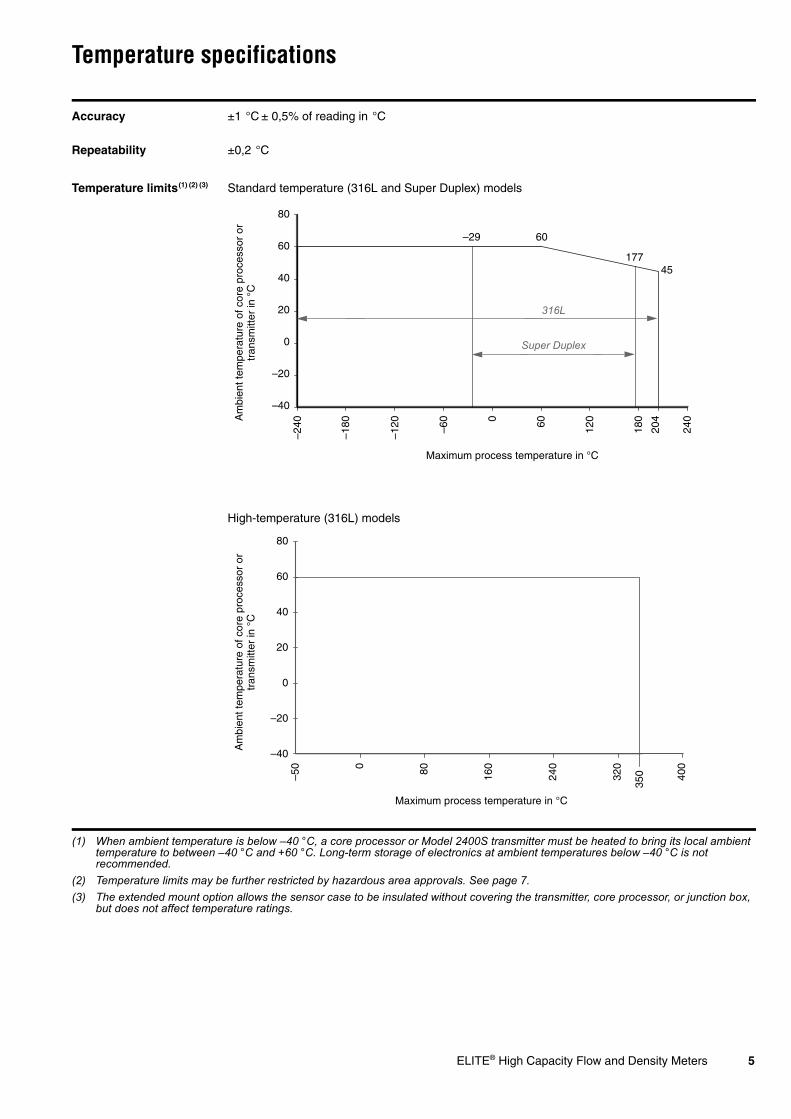
Temperature specifications
Accuracy ±1 °C ± 0,5% of reading in °C
Repeatability ±0,2 °C
Temperature limits(1) (2) (3)
(1) When ambient temperature is below –40 °C, a core processor or Model 2400S transmitter must be heated to bring its local ambient temperature to between –40 °C and +60 °C. Long-term storage of electronics at ambient temperatures below –40 °C is not recommended.
(2) Temperature limits may be further restricted by hazardous area approvals. See page 7.(3) The extended mount option allows the sensor case to be insulated without covering the transmitter, core processor, or junction box,
but does not affect temperature ratings.
Standard temperature (316L and Super Duplex) models
High-temperature (316L) models
Am
bien
t tem
pera
ture
of c
ore
proc
esso
r or
tr
ansm
itter
in °
C
Maximum process temperature in °C
–40
–20
0
20
40
60
80
–240
–180
–120 –60 0 60 180
240
120
45
204
60
Super Duplex
177
–29
316L
–40
–20
0
20
40
60
80
350–5
0 0
240
16080 400
320
Maximum process temperature in °C
Am
bien
t tem
pera
ture
of c
ore
proc
esso
r or
tr
ansm
itter
in °
C
6 ELITE® High Capacity Flow and Density Meters
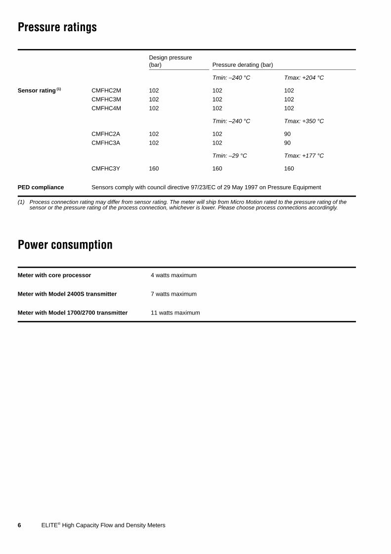
Pressure ratings
Power consumption
Design pressure(bar) Pressure derating (bar)
Tmin: –240 °C Tmax: +204 °C
Sensor rating (1)
(1) Process connection rating may differ from sensor rating. The meter will ship from Micro Motion rated to the pressure rating of the sensor or the pressure rating of the process connection, whichever is lower. Please choose process connections accordingly.
CMFHC2M 102 102 102
CMFHC3M 102 102 102
CMFHC4M 102 102 102
Tmin: –240 °C Tmax: +350 °C
CMFHC2A 102 102 90
CMFHC3A 102 102 90
Tmin: –29 °C Tmax: +177 °C
CMFHC3Y 160 160 160
PED compliance Sensors comply with council directive 97/23/EC of 29 May 1997 on Pressure Equipment
Meter with core processor 4 watts maximum
Meter with Model 2400S transmitter 7 watts maximum
Meter with Model 1700/2700 transmitter 11 watts maximum
ELITE® High Capacity Flow and Density Meters 7
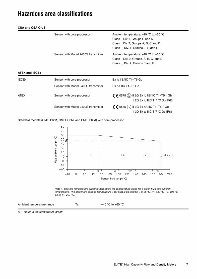
Hazardous area classifications
CSA and CSA C-US
Sensor with core processor Ambient temperature: –40 °C to +60 °C
Class I, Div 1, Groups C and D
Class I, Div 2, Groups A, B, C and D
Class II, Div. 1, Groups E, F, and G
Sensor with Model 2400S transmitter Ambient temperature: –40 °C to +60 °C
Class I, Div. 2, Groups, A, B, C, and D
Class II, Div. 2, Groups F and G
ATEX and IECEx
IECEx Sensor with core processor Ex ib IIB/IIC T1–T5 Gb
Sensor with Model 2400S transmitter Ex nA IIC T1–T5 Gc
ATEX Sensor with core processor 0575 II 2G Ex ib IIB/IIC T1–T5(1) Gb
(1) Refer to the temperature graph.
II 2D Ex ib IIIC T(1) °C Db IP65
Sensor with Model 2400S transmitter 0575 II 3G Ex nA IIC T1–T5(1) Gc
II 3D Ex tc IIIC T(1) °C Dc IP65
Standard models (CMFHC2M, CMFHC3M, and CMFHC4M) with core processor
Ambient temperature range Ta –40 °C to +60 °C
Sensor fluid temp (°C)
Max
am
bien
t tem
p (°
C)
Note 1: Use the temperature graph to determine the temperature class for a given fluid and ambient temperature. The maximum surface temperature T for dust is as follows: T5: 95 °C, T4: 130 °C, T3: 195 °C, T2 to T1: 207 °C.

8 ELITE® High Capacity Flow and Density Meters
Hazardous area classifications
ATEX and IECEx
High-temperature models (CMFHC2A and CMFHC3A) with core processor
Ambient temperature range Ta –50 °C to +55 °C
Super Duplex models (CMFHC3Y) with core processor
Ambient temperature range Ta –40 °C to +60 °C
Sensor fluid temp (°C)
Max
am
bien
t tem
p (°
C)
Note 1: Use the temperature graph to determine the temperature class for a given fluid and ambient temperature. The maximum surface temperature T for dust is as follows: T5: 95 °C, T4: 130 °C, T3: 195 °C, T2: 290 °C, T1: 363 °C. The minimum ambient and process fluid temperature allowed for dust is –40 °C.
Sensor fluid temp (°C)
Max
am
bien
t tem
p (°
C)
Note 1: Use the temperature graph to determine the temperature class for a given fluid and ambient temperature. The maximum surface temperature T for dust is as follows: T5: 95 °C, T4: 130 °C, T3: 195 °C, T2 to T1: 207 °C. The minimum ambient and process fluid temperature allowed for dust is –40 °C.

ELITE® High Capacity Flow and Density Meters 9
Materials of construction
Weight and center of gravity
Wetted parts(1)
(1) General corrosion guides do not account for cyclical stress, and therefore should not be relied upon when choosing a wetted material for your Micro Motion sensor. Please refer to the Micro Motion corrosion guide for proper material compatibility information.
316L stainless steel or Super Duplex (UNS S32750)
Housing 304L stainless steel(2)
(2) 316L stainless steel is available.
Core processor Polyurethane-painted aluminum or 300-series stainless steel (2); NEMA 4X (IP66)
Model 2400S transmitter Polyurethane-painted aluminum or 300-series stainless steel(2); NEMA 4X (IP66)
Weight includes the weight of the sensor with CL150 weld neck raised face flanges, plus the weight of the core processor or Model 2400S transmitter.
kg
Weight CMFHC2 248
CMFHC3 356
CMFHC4 599
Center of gravity is based on a sensor with integral core processor or Model 2400S transmitter, with meter empty of fluid. Value shown with CL150 flange. Exact center of gravity will vary with the weight of the flange.
Dim. A (mm)
Center of gravity CMFHC2 338
CMFHC3 365
CMFHC4 465
Dim. A
10 ELITE® High Capacity Flow and Density Meters
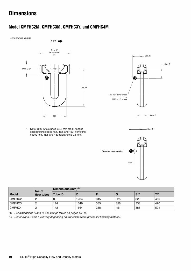
Dimensions
Model CMFHC2M, CMFHC3M, CMFHC3Y, and CMFHC4M
ModelNo. of flow tubes
Dimensions (mm)(1)
(1) For dimensions A and B, see fittings tables on pages 13–15.
Tube ID D F G S(2)
(2) Dimensions S and T will vary depending on transmitter/core processor housing material.
T(2)
CMFHC2 2 89 1234 315 325 323 460
CMFHC3 2 114 1349 335 356 338 470
CMFHC4 2 142 1664 358 451 385 521
Dimensions in mm
Dim. Ø B*
Dim. A* face-to-face
±5
Flow
Ø32
Extended mount option
Dim. S
Dim. D
839
Dim. F
2 × 1/2”–NPT femaleor
M20 × 1,5 female
Dim. G
Dim. T* Note: Dim. A tolerance is ±5 mm for all flanges except fitting codes 451, 452, and 453. For fitting codes 451, 452, and 453 tolerance is ±3 mm.

ELITE® High Capacity Flow and Density Meters 11
Dimensions continued
Models CMFHC2A and CMFHC3A
Model
Dimensions (mm)
F Q
CMFHC2A 315 228
CMFHC3A 335 258
Dimensions in mm Dim. Q
Dim. F
Ø33
Flexible conduitMinimum bend radius
171 mm
* For additional sensor dimensions, see page 10.
1187
79

12 ELITE® High Capacity Flow and Density Meters
Dimensions continued
Electronics mounted on high-temperature sensor flexible conduit
Electronics interface option Dim. C (mm)
0 Model 2400S transmitter, painted aluminum housing 225
Model 2400S transmitter, stainless steel housing 235
2 Core processor, painted aluminum housing 225
3 Core processor, stainless steel housing 235
Dimensions in mm
Dim. C
4 × Ø10
3636
36
36
116
2 × 1/2”–14 NPT femaleor M20 × 1,5 female

ELITE® High Capacity Flow and Density Meters 13
Fitting options
Model CMFHC2
Process fitting
Code(1)
(1) Fittings listed here are standard options. Other types of fittings are available. The face to face dimensions for any custom fittings ordered using a 998 or 999 fitting code are not represented in this table. It is necessary to confirm face to face dimensions of these fittings at time of ordering. Contact your local Micro Motion representative.
Dim. A(2) face-to-face(mm)
(2) Tolerance for Dim. A is ±5 mm for all fittings except codes 451, 452, and 453. For codes 451, 452, and 453 tolerance is ±3 mm.
Dim. B outside dia.(mm)316L
6-inch ANSI CL150 weld neck raised face flange 451 1087 279
6-inch ANSI CL300 weld neck raised face flange 452 1107 318
6-inch ANSI CL600 weld neck raised face flange 453 1157 356
6-inch ANSI CL900 weld neck raised face flange 821 1201 381
8-inch ANSI CL150 weld neck raised face flange 810 1111 343
8-inch ANSI CL300 weld neck raised face flange 811 1131 381
8-inch ANSI CL600 weld neck raised face flange 818 1187 419
8-inch ANSI CL900 weld neck raised face flange 819 1245 470
DN150 PN40 weld neck flange; EN 1092-1 Form B1 822 1059 300
DN150 PN100 weld neck flange; EN 1092-1 Form B2 823 1139 355
DN150 PN160 weld neck flange; EN 1092-1 Form B2 824 1165 355
DN200 PN40 weld neck flange; EN 1092-1 Form B1 801 1084 375
DN200 PN100 weld neck flange; EN 1092-1 Form B2 802 1168 430
DN200 PN160 weld neck flange; EN 1092-1 Form B2 803 1188 430

14 ELITE® High Capacity Flow and Density Meters
Fitting options continued
Model CMFHC3
Process fitting
Code(1)
(1) Fittings listed here are standard options. Other types of fittings are available. The face to face dimensions for any custom fittings ordered using a 998 or 999 fitting code are not represented in this table. It is necessary to confirm face to face dimensions of these fittings at time of ordering. Contact your local Micro Motion representative.
Dim. A(2) face-to-face(mm)
(2) Tolerance for Dim. A is ±5 mm.
Dim. B outside dia.(mm)316L
Super Duplex
8-inch ANSI CL150 weld neck raised face flange 810 831 1111 343
8-inch ANSI CL300 weld neck raised face flange 811 832 1131 381
8-inch ANSI CL600 weld neck raised face flange 818 833 1187 419
8-inch ANSI CL600 lap joint flange 812 — 1187 419
8-inch ANSI CL900 weld neck raised face flange 819 834 1245 470
10-inch ANSI CL150 weld neck raised face flange 813 836 1114 406
10-inch ANSI CL300 weld neck raised face flange 814 837 1143 445
10-inch ANSI CL600 weld neck raised face flange 815 838 1203 508
10-inch ANSI CL600 lap joint flange 816 — 1264 508
10-inch ANSI CL600 weld neck raised face PD replacement flange
817 — 1119 508
10-inch ANSI CL900 weld neck raised face flange 820 839 1258 546
DN200 PN40 weld neck flange; EN 1092-1 Form B1 801 825 1084 375
DN200 PN100 weld neck flange; EN 1092-1 Form B2 802 826 1168 430
DN200 PN160 weld neck flange; EN 1092-1 Form B2 803 827 1188 430
DN250 PN40 weld neck flange; EN 1092-1 Form B1 804 828 1118 450
DN250 PN100 weld neck flange; EN 1092-1 Form B2 805 829 1222 505
DN250 PN160 weld neck flange; EN 1092-1 Form B2 806 830 1218 515

ELITE® High Capacity Flow and Density Meters 15
Fitting options continued
Model CMFHC4
Process fitting
Code(1)
(1) Fittings listed here are standard options. Other types of fittings are available. The face to face dimensions for any custom fittings ordered using a 998 or 999 fitting code are not represented in this table. It is necessary to confirm face to face dimensions of these fittings at time of ordering. Contact your local Micro Motion representative.
Dim. A(2) face-to-face(mm)
(2) Tolerance for Dim. A is ±5 mm.
Dim. B outside dia.(mm)316L
10-inch ANSI CL150 weld neck raised face flange 841 1213 406
10-inch ANSI CL300 weld neck raised face flange 842 1244 445
10-inch ANSI CL600 weld neck raised face flange 843 1327 508
10-inch ANSI CL900 weld neck raised face flange 844 1391 546
12-inch ANSI CL150 weld neck raised face flange 845 1238 483
12-inch ANSI CL300 weld neck raised face flange 846 1270 521
12-inch ANSI CL600 weld neck raised face flange 847 1333 559
12-inch ANSI CL900 weld neck raised face flange 848 1423 610
DN250 PN40 weld neck flange; EN 1092-1 Form B1 849 1220 450
DN250 PN100 weld neck flange; EN 1092-1 Form B2 850 1324 505
DN250 PN160 weld neck flange; EN 1092-1 Form B2 851 1320 515
DN300 PN40 weld neck flange; EN 1092-1 Form B1 852 1240 515
DN300 PN100 weld neck flange; EN 1092-1 Form B2 853 1350 585
DN300 PN160 weld neck flange; EN 1092-1 Form B2 854 1360 585

16 ELITE® High Capacity Flow and Density Meters
Ordering information
Standard models
Model Product description
CMFHC2M Micro Motion Coriolis ELITE sensor; 150 to 200 mm; 316L stainless steel
CMFHC3M Micro Motion Coriolis ELITE sensor; 200 to 250 mm; 316L stainless steel
CMFHC4M Micro Motion Coriolis ELITE sensor; 250 to 300 mm; 316L stainless steel
Code Process connections
### See process fitting options on pages 13–15.
Code Case options
N Standard pressure containment
Code Electronics interface
0 Model 2400S transmitter
1 Extended mount Model 2400S transmitter
2 4-wire polyurethane-painted aluminum integral core processor for remote mount transmitters
3 4-wire stainless steel integral core processor for remote mount transmitters
4 4-wire polyurethane-painted aluminum integral extended mount core processor for remote mount transmitters
5 4-wire stainless steel integral extended mount core processor for remote mount transmitters
Code Conduit connections
Electronics interface codes 0 and 1
A No gland
Electronics interface codes 2, 3, 4, and 5
B 1/2-inch NPT – no gland
E M20 – no gland
F Brass/nickel cable gland (cable diameter 8,5 to 10 mm)
G Stainless steel cable gland (cable diameter 8,5 to 10 mm)
Code Approvals
Electronics interface codes 0 and 1
M Micro Motion Standard (no approval)
N Micro Motion Standard / PED compliant
2 CSA Class I, Div. 2
V ATEX Equipment Category 3 (Zone 2) / PED compliant
3 IECEx Zone 2
Electronics interface codes 2, 3, 4, and 5
M Micro Motion Standard (no approval)
N Micro Motion Standard / PED compliant
A CSA C-US (U.S.A. and Canada)
Z ATEX Equipment Category 2 (Zone 1) / PED compliant
I IECEx Zone 1
6 ATEX Equipment Category 2 (Zone 1 – IIC modified) / PED compliant
7 IECEx Zone 1 – IIC modified
Continued on next page

ELITE® High Capacity Flow and Density Meters 17
Ordering information continued
Standard models
Code Language
A Danish CE requirements document and English installation manual
D Dutch CE requirements document and English installation manual
E English installation manual
F French installation manual
G German installation manual
H Finnish CE requirements document and English installation manual
I Italian installation manual
J Japanese installation manual
M Chinese installation manual
N Norwegian CE requirements document and English installation manual
O Polish installation manual
P Portuguese installation manual
S Spanish installation manual
W Swedish CE requirements document and English installation manual
C Czech installation manual
B Hungarian CE requirements document and English installation manual
K Slovak CE requirements document and English installation manual
T Estonian CE requirements document and English installation manual
U Greek CE requirements document and English installation manual
L Latvian CE requirements document and English installation manual
V Lithuanian CE requirements document and English installation manual
Y Slovenian CE requirements document and English installation manual
Code Calibration options
Z 0,10% mass flow and 0,5 kg/m3 density
Code Measurement application software
Z No measurement application software
Code Factory options
Z Standard product
X ETO product
Typical Model Number: CMFHC3M 801 N 2 E Z E Z Z Z

18 ELITE® High Capacity Flow and Density Meters
Ordering information continued
Super Duplex models
Model Product description
CMFHC3Y Micro Motion Coriolis ELITE sensor; 200 to 250 mm; Super Duplex
Code Process connections
### See process fitting options on pages 13–15.
Code Case options
N Standard pressure containment
Code Electronics interface
0 Model 2400S transmitter
1 Extended mount Model 2400S transmitter
2 4-wire polyurethane-painted aluminum integral core processor for remote mount transmitters
3 4-wire stainless steel integral core processor for remote mount transmitters
4 4-wire polyurethane-painted aluminum integral extended mount core processor for remote mount transmitters
5 4-wire stainless steel integral extended mount core processor for remote mount transmitters
Code Conduit connections
Electronics interface codes 0 and 1
A No gland
Electronics interface codes 2, 3, 4, and 5
B 1/2-inch NPT — no gland
E M20 — no gland
F Brass/nickel cable gland (cable diameter 8,5 to 10 mm)
G Stainless steel cable gland (cable diameter 8,5 to 10 mm)
Code Approvals
Electronics interface codes 0 and 1
M Micro Motion Standard (no approval)
N Micro Motion Standard / PED compliant
2 CSA Class I, Div. 2
V ATEX Equipment Category 3 (Zone 2) / PED compliant
3 IECEx Zone 2
Electronics interface codes 2, 3, 4, and 5
M Micro Motion Standard (no approval)
N Micro Motion Standard / PED compliant
A CSA C-US (U.S.A. and Canada)
Z ATEX Equipment Category 2 (Zone 1) / PED compliant
I IECEx Zone 1
6 ATEX Equipment Category 2 (Zone 1 – IIC modified) / PED compliant
7 IECEx Zone 1 – IIC modified
Continued on next page

ELITE® High Capacity Flow and Density Meters 19
Ordering information continued
Super Duplex models
Code Language
A Danish CE requirements document and English installation manual
D Dutch CE requirements document and English installation manual
E English installation manual
F French installation manual
G German installation manual
H Finnish CE requirements document and English installation manual
I Italian installation manual
J Japanese installation manual
M Chinese installation manual
N Norwegian CE requirements document and English installation manual
O Polish installation manual
P Portuguese installation manual
S Spanish installation manual
W Swedish CE requirements document and English installation manual
C Czech installation manual
B Hungarian CE requirements document and English installation manual
K Slovak CE requirements document and English installation manual
T Estonian CE requirements document and English installation manual
U Greek CE requirements document and English installation manual
L Latvian CE requirements document and English installation manual
V Lithuanian CE requirements document and English installation manual
Y Slovenian CE requirements document and English installation manual
Code Calibration options
Z 0,10% mass flow and 0,5 kg/m3 density
Code Measurement application software
Z No measurement application software
Code Factory options
Z Standard product
X ETO product
Typical Model Number: CMFHC3Y 825 N 2 E Z E Z Z Z

20 ELITE® High Capacity Flow and Density Meters
Ordering information continued
High-temperature models
Model Product description
CMFHC2A Micro Motion Coriolis ELITE sensor; 150 to 200 mm; high temperature; 316L stainless steel
CMFHC3A Micro Motion Coriolis ELITE sensor; 200 to 250 mm; high temperature; 316L stainless steel
Code Process connections
### See process fitting options on pages 13–15.
Code Case options
N Standard pressure containment
Code Electronics interface
0 Model 2400S transmitter
2 4-wire polyurethane-painted aluminum integral core processor for remote mount transmitters
3 4-wire stainless steel integral core processor for remote mount transmitters
Code Conduit connections
Electronics interface codes 0 and 1
A No gland
Electronics interface codes 2, 3, 4, and 5
B 1/2-inch NPT – no gland
E M20 – no gland
F Brass/nickel cable gland (cable diameter 8,5 to 10 mm)
G Stainless steel cable gland (cable diameter 8,5 to 10 mm)
Code Approvals
Electronics interface codes 0 and 1
M Micro Motion Standard (no approval)
N Micro Motion Standard / PED compliant
2 CSA Class I, Div. 2
V ATEX Equipment Category 3 (Zone 2) / PED compliant
3 IECEx Zone 2
Electronics interface codes 2, 3, 4, and 5
M Micro Motion Standard (no approval)
N Micro Motion Standard / PED compliant
A CSA C-US (U.S.A. and Canada)
Z ATEX Equipment Category 2 (Zone 1) / PED compliant
I IECEx Zone 1
6 ATEX Equipment Category 2 (Zone 1 – IIC modified) / PED compliant
7 IECEx Zone 1 – IIC modified
Continued on next page
ELITE® High Capacity Flow and Density Meters 21
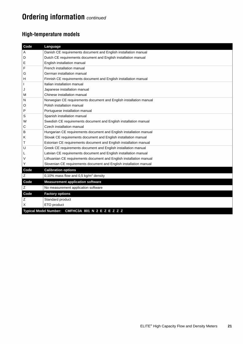
Ordering information continued
High-temperature models
Code Language
A Danish CE requirements document and English installation manual
D Dutch CE requirements document and English installation manual
E English installation manual
F French installation manual
G German installation manual
H Finnish CE requirements document and English installation manual
I Italian installation manual
J Japanese installation manual
M Chinese installation manual
N Norwegian CE requirements document and English installation manual
O Polish installation manual
P Portuguese installation manual
S Spanish installation manual
W Swedish CE requirements document and English installation manual
C Czech installation manual
B Hungarian CE requirements document and English installation manual
K Slovak CE requirements document and English installation manual
T Estonian CE requirements document and English installation manual
U Greek CE requirements document and English installation manual
L Latvian CE requirements document and English installation manual
V Lithuanian CE requirements document and English installation manual
Y Slovenian CE requirements document and English installation manual
Code Calibration options
Z 0,10% mass flow and 0,5 kg/m3 density
Code Measurement application software
Z No measurement application software
Code Factory options
Z Standard product
X ETO product
Typical Model Number: CMFHC3A 801 N 2 E Z E Z Z Z

22 ELITE® High Capacity Flow and Density Meters

ELITE® High Capacity Flow and Density Meters 23

Micro Motion—The undisputed leader in flow and density measurement
WWW.micromotion.com
�������������� � ����������������������� ������������ ����������������������������������������������� !����"##$#��� !�%���&"#�"#��' !�%���&"���(")*+��� � "#"""��)"�����,����� � "(��(����������-�� � ""�"�#���"#�.�-��� � "�#$��)#��"�
�������������� � ������������������������������� ��
��/�������� � !�����()""""��,��0 � !�##��$����
�121 � ����#(��)��3�����4�5� � !�()")��)���
5���6 � ��������(7�0��6 � ������#"�(�'���� � ����)��)��8�9�� � !)��(�������������:;�����;���< � !(�(��$�$���
�������������� � �������������������� �����
���,�<�� � %$"&$����#��2��� � %�#&#�(��($��=�<�� � %��&�"�$)$���5���� � %)�&##$$$#�"$$����� � %�$&#�#�)#)������������ � %$�&�)�#��#��
�<��� � !�()��"�$���
World-leading Micro Motion measurement solutions from Emerson Process Management deliver what you need most:
Technology leadershipMicro Motion introduced the first reliable Coriolis meter in 1977. Since that time, our ongoing product development has enabled us to provide the highest performing measurement devices available.
Product breadthFrom compact, drainable process control to high flow rate fiscal transfer—look no further than Micro Motion for the widest range of measurement solutions.
Unparalleled valueBenefit from expert phone, field, and application service and support made possible by more than 600000 meters installed worldwide and over 30 years of flow and density measurement experience.
© 2011 Micro Motion, Inc. All rights reserved.
The Emerson logo is a trademark and service mark of Emerson Electric Co. Micro Motion, ELITE, ProLink, MVD and MVD Direct Connect are marks of one of the Emerson Process Management family of companies. All other trademarks are property of their respective owners.
Micro Motion supplies this publication for informational purposes only. While every effort has been made to ensure accuracy, this publication is not intended to make performance claims or process recommendations. Micro Motion does not warrant, guarantee, or assume any legal liability for the accuracy, completeness, timeliness, reliability, or usefulness of any information, product, or process described herein. We reserve the right to modify or improve the designs or specifications of our products at any time without notice. For actual product information and recommendations, please contact your local Micro Motion representative.
For a complete list of contact information and web sites, please visit: www.emersonprocess.com/home/contacts/global