
ELFOEnergy Magnum - Cooling only - Cooke Industries · ELFOEnergy Magnum - Cooling only. Nominal...
36
ELFOEnergy Magnum - Cooling only Nominal cooling capacity (A35/W7) from 50 kW to 125 kW ▶ SCROLL INVERTER R-410A TECHNOLOGY ▶ TWO INDEPENDENT REFRIGERATION CIRCUITS ▶ EUROVENT CLASS A IN COOLING ▶ ECOBREEZE FANS Silent operation and reduced fan consumptions ▶ PARTIAL RECOVERY OF THE CONDENSING HEAT (OPTIONAL) ▶ AXITOP FAN (OPTIONAL) For a further increase in efficiency ▶ VARYFLOW+ (OPTIONAL) Variable water flow-rate with inverter pumps Technical Bulletin Air-cooled liquid chiller for outdoor installation WSAT-XIN 18.2 - 45.2 RANGE Clivet is taking part in the EUROVENT certification programme up to 1.500 kW. The products concerned appear in the certified products list of the EUROVENT www.eurovent-certification.com site. BT15N007GB-03 Cooke Industries - Phone: +64 9 579 2185 Fax: +64 9 579 2181 Email: [email protected] Web: www.cookeindustries.co.nz
Transcript of ELFOEnergy Magnum - Cooling only - Cooke Industries · ELFOEnergy Magnum - Cooling only. Nominal...
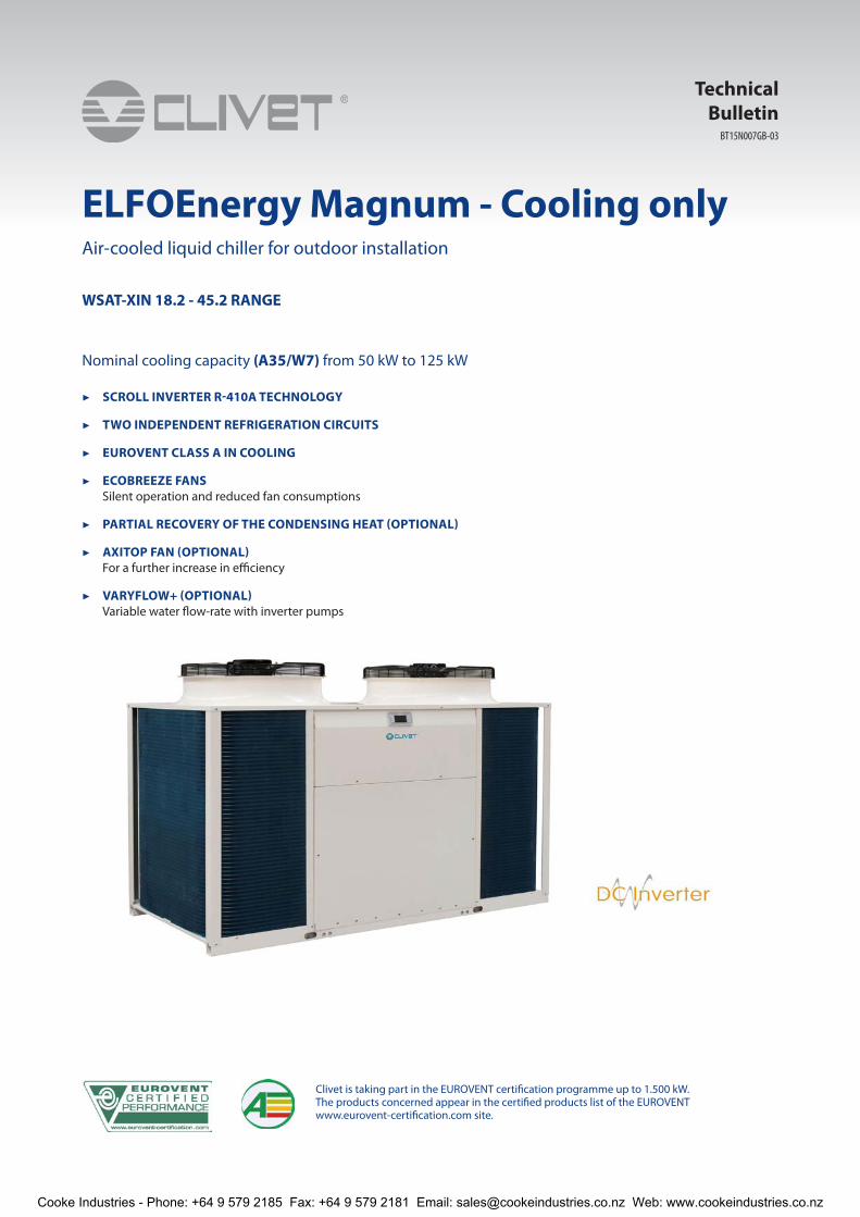
ELFOEnergy Magnum - Cooling only
Nominal cooling capacity (A35/W7) from 50 kW to 125 kW
▶ SCROLL INVERTER R-410A TECHNOLOGY
▶ TWO INDEPENDENT REFRIGERATION CIRCUITS
▶ EUROVENT CLASS A IN COOLING
▶ ECOBREEZE FANSSilent operation and reduced fan consumptions
▶ PARTIAL RECOVERY OF THE CONDENSING HEAT (OPTIONAL)
▶ AXITOP FAN (OPTIONAL)For a further increase in efficiency
▶ VARYFLOW+ (OPTIONAL)Variable water flow-rate with inverter pumps
Technical Bulletin
Air-cooled liquid chiller for outdoor installation
WSAT-XIN 18.2 - 45.2 RANGE
Clivet is taking part in the EUROVENT certification programme up to 1.500 kW. The products concerned appear in the certified products list of the EUROVENT www.eurovent-certification.com site.
BT15N007GB-03
Cooke Industries - Phone: +64 9 579 2185 Fax: +64 9 579 2181 Email: [email protected] Web: www.cookeindustries.co.nz
2 ELFOEnergy Magnum BT15N007GB-03
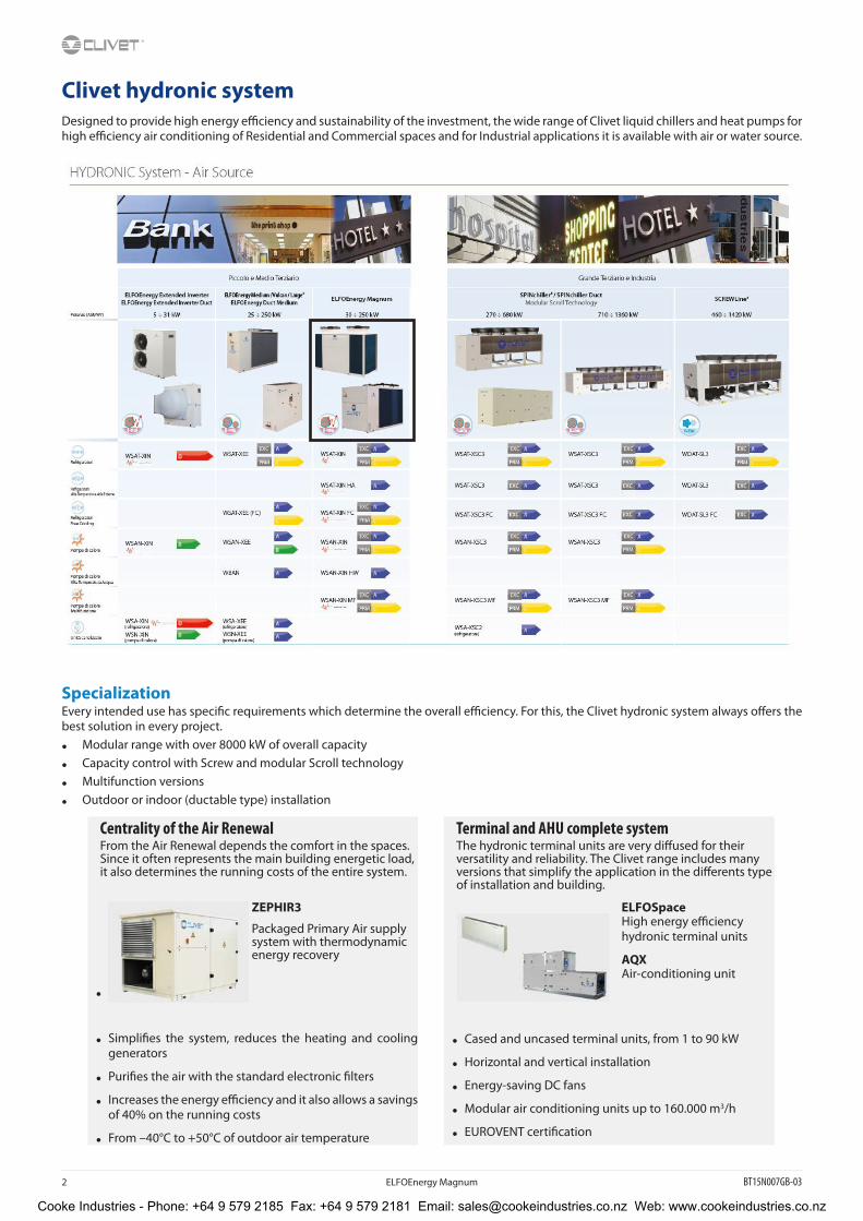
Clivet hydronic systemDesigned to provide high energy efficiency and sustainability of the investment, the wide range of Clivet liquid chillers and heat pumps for high efficiency air conditioning of Residential and Commercial spaces and for Industrial applications it is available with air or water source.
SpecializationEvery intended use has specific requirements which determine the overall efficiency. For this, the Clivet hydronic system always offers the best solution in every project.
• Modular range with over 8000 kW of overall capacity
• Capacity control with Screw and modular Scroll technology
• Multifunction versions
• Outdoor or indoor (ductable type) installation
Centrality of the Air Renewal Terminal and AHU complete systemFrom the Air Renewal depends the comfort in the spaces. Since it often represents the main building energetic load, it also determines the running costs of the entire system.
The hydronic terminal units are very diffused for their versatility and reliability. The Clivet range includes many versions that simplify the application in the differents type of installation and building.
•
ZEPHIR3
Packaged Primary Air supply system with thermodynamic energy recovery
ELFOSpaceHigh energy efficiency hydronic terminal units
AQXAir-conditioning unit
• Cased and uncased terminal units, from 1 to 90 kW
• Horizontal and vertical installation
• Energy-saving DC fans
• Modular air conditioning units up to 160.000 m3/h
• EUROVENT certification
• Simplifies the system, reduces the heating and cooling generators
• Purifies the air with the standard electronic filters
• Increases the energy efficiency and it also allows a savings of 40% on the running costs
• From –40°C to +50°C of outdoor air temperature
Cooke Industries - Phone: +64 9 579 2185 Fax: +64 9 579 2181 Email: [email protected] Web: www.cookeindustries.co.nz
BT15N007GB-03 ELFOEnergy Magnum 3
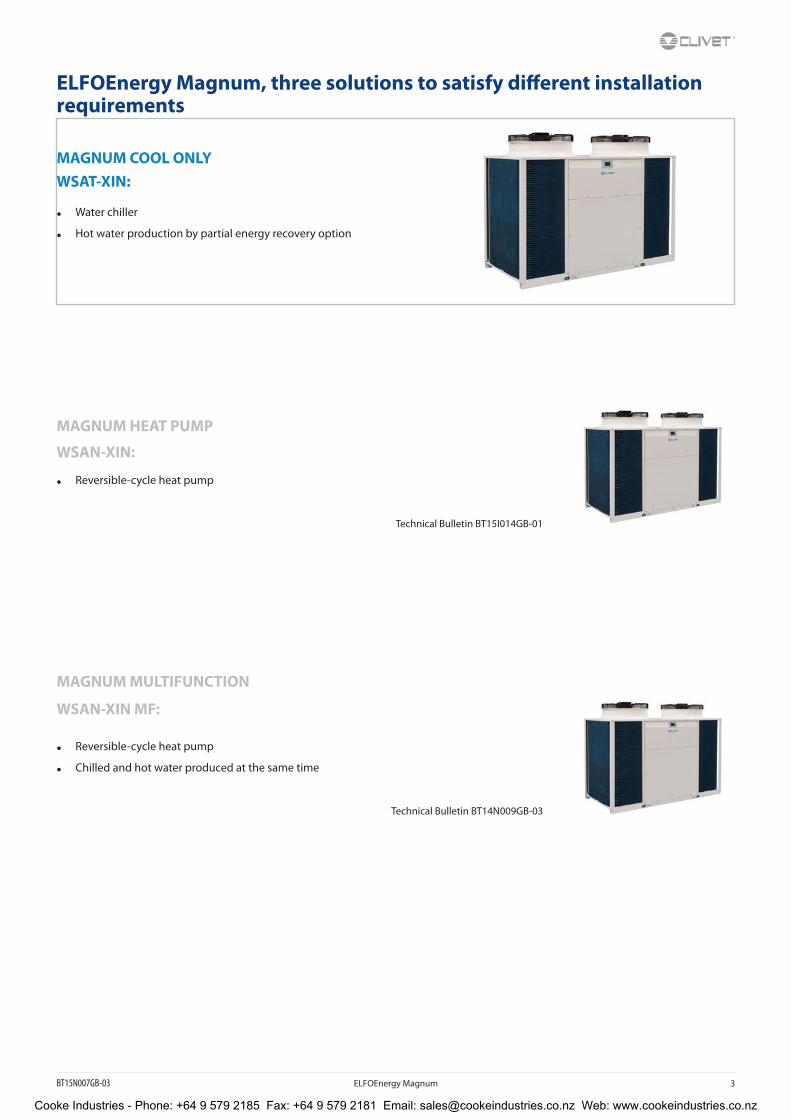
ELFOEnergy Magnum, three solutions to satisfy different installation requirements
MAGNUM COOL ONLYWSAT-XIN:
• Water chiller
• Hot water production by partial energy recovery option
MAGNUM HEAT PUMP
WSAN-XIN:
• Reversible-cycle heat pump
Technical Bulletin BT15I014GB-01
MAGNUM MULTIFUNCTION
WSAN-XIN MF:
• Reversible-cycle heat pump
• Chilled and hot water produced at the same time
Technical Bulletin BT14N009GB-03
Cooke Industries - Phone: +64 9 579 2185 Fax: +64 9 579 2181 Email: [email protected] Web: www.cookeindustries.co.nz
4 ELFOEnergy Magnum BT15N007GB-03
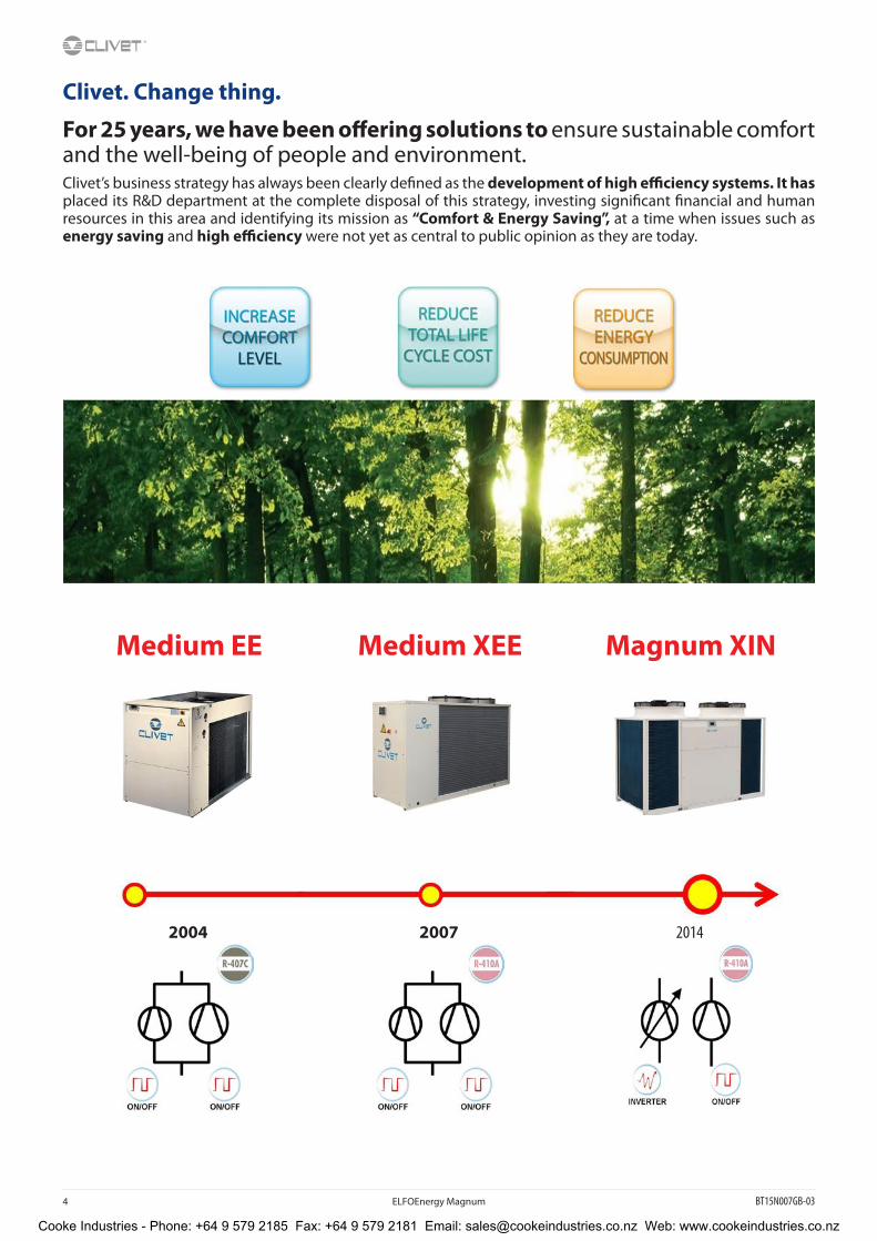
Clivet. Change thing.
For 25 years, we have been offering solutions to ensure sustainable comfort and the well-being of people and environment.Clivet’s business strategy has always been clearly defined as the development of high efficiency systems. It has placed its R&D department at the complete disposal of this strategy, investing significant financial and human resources in this area and identifying its mission as “Comfort & Energy Saving”, at a time when issues such as energy saving and high efficiency were not yet as central to public opinion as they are today.
Medium EE Medium XEE Magnum XIN
2004 2007 2014
Cooke Industries - Phone: +64 9 579 2185 Fax: +64 9 579 2181 Email: [email protected] Web: www.cookeindustries.co.nz

BT15N007GB-03 ELFOEnergy Magnum 5
Maximum efficiency is necessary with a part load
Load variability
Cooling capacity required from the air conditioning system typically varies over the year and often even in the course of the same day.
Climatic conditions vary depending on the place consequently also the load‘s trend.
The highest values appear for limited periods of time, often coinciding with the most demanding weather conditions.
Maximum efficiency is necessary with a part load
Since the maximum power generated by the system is requested only for short periods of time, it is fundamental to dispose of the maximum efficiency in the conditions of part-load.
This is the only way to actually reduce overall yearly consumptions.
ELFOEnergy Magnum
The most advanced technologies, enclosed in a single compact unit, combined with the reliability advantages of the double refrigeration circuit, guarantee the best seasonal efficiency.
Cooke Industries - Phone: +64 9 579 2185 Fax: +64 9 579 2181 Email: [email protected] Web: www.cookeindustries.co.nz

6 ELFOEnergy Magnum BT15N007GB-03
High seasonal efficiency thanks to the capacity continuous modulation
The progressive and sequential activation of the two refrigeration circuits, one controlled by inverter technology, guarantees the complete adjustment to the installation load.
The capacity modultation is necessary starting from minimum values which guarantee the continuous capacity supply depending on the requirements.
Control of the refrigerant flow
The load variability involves the continuous variation of the refrigerant volume moved by compressors.
The electronic expansion valve (EEV), standard on Clivet units, adapts rapidly and precisely to the actual load required for usage, allowing stable and reliable control in comparison with mechanical thermostatic valves (TEV). This results also in a further increase in efficiency and longer compressor life.
The overheating control allows preventing phenomena that are hazardous to the compressors, such as overtemperature and return fluids, thereby increasing even more efficiency and durability.
Efficient heat exchange
The new plate exchanger design allows an higher evaporating temperature, guaranteeing a better exchange efficiency, above all in the part-load operating that coincides with the most of the unit operating time.
Standard supplied ECOBREEZE fans, electronically controlled.
With ECOBREEZE, the electric motor with an external rotor is driven by the continuous magnetic switching of the stator, deriving from the integrated electronic control.
User benefits:
• 70% increase in efficiency thanks to the brushless technology and the special electricity supply;
• increase in the working life, thanks to the elimination of the brush wear;
• reduction in the electrical consumption by the system, thanks to a drastic reduction of the inrush current for the fans obtained using the integrated ‘Soft starter’ function.
Fans at variable speed for minimal noise emission
All units are equipped with electronic condensation control. It automatically reduces the fan speed when the heat load is reduced.
Since the fans are the unit’s main noise source, the benefits are evident especially during the night hours, when the load is reduced but sensitivity to noise is enhanced.
All this translates into a reduction of sound pressure down to 8 dB(A) compared to full load operation in 90% of operating time of the unit.
Cooke Industries - Phone: +64 9 579 2185 Fax: +64 9 579 2181 Email: [email protected] Web: www.cookeindustries.co.nz

BT15N007GB-03 ELFOEnergy Magnum 7
Efficient and silent ventilation technology (optional)
It is possible to further increase the seasonal efficiency with the innovative air handling system on the external exchangers.
The new AxiTop diffuser creates an ideal air distribution: it aerodynamically decelerates the flow and transforms a big part of its kinetic energy in static pressure.
All AXITOP components are aerodinamically optimized enhancing significantly the efficiency and reducing the impeller speed and consequently the noise.
Obtaining:
• down to –3 dB of silence
• reduction of 3% of the absorbed energy
Water flow-rate continuous modulation (optional)
The energy used for the vector pumping is fundamental on the seasonal efficiency.
The VARYFLOW+ modulating pumping unit made up of two pumps in parallel controlled by inverter, allows a precise water flow-rate modulation reducing notably the consumptions and at the same time it guarantees its functionality also in case of temporary unavailability of one of the two pumps, guaranteeing about the 80% of the nominal flow-rate.
The water flow-rate modulation can be managed in function of the installation pressure or keeping constant the delta between return and supply temperature.
If the installation water temperature is in critical conditions, VARYFLOW+ allows to extend the ELFOEnergy Magnum operating ranges guaranteeing the operating.
In case of particular installation needs, the hydronic assemblies are also available:
• ON/OFF pump: the traditional solution with high available pressure.
• ON/OFF pump + ON/OFF pump in stand-by: the solution that favours reliability. The built-in control balances the operating hours of the two pump and in case of any failure it signals the damage and automatically activates the stand-by pump.
Integrated inertial storage tank available (optional)
Available only for size 35.2 ÷ 45.2.
In most Magnum systems it can be installed without inertial storage tank on the system. In fact, the unit quickly adapts to the load due to modular compressors, electronic thermostatic valve and low water content plate heat exchangers. However, in the event of hydraulic distribution networks with reduced dimensions, it is important to provide the system with a hydraulic flywheel. In such cases, inertial storage tank is available built-in, equipped with insulating coating and all the necessary safety devices. This allows eliminating installation times and costs and freeing space inside the building.
Produces hot water freely (optional)
Condensation heat partial recovery:
• it recovers about the 20% of the available heat (desuperheater)
It allows the free DHW production for:
• Hot water coil supply for reheat
• Domestic hot water production (with intermediate exchanger)
• Other processes or operations
Cooke Industries - Phone: +64 9 579 2185 Fax: +64 9 579 2181 Email: [email protected] Web: www.cookeindustries.co.nz

8 ELFOEnergy Magnum BT15N007GB-03
Advanced control
The control system combines in a single solution the operating efficiency and the user-friendliness.
Continuously monitoring all of the unit operating parameters, it ensures the maintenance of an optimal energy efficiency.
The control includes many safety functions and a complete alarm management.
It also includes advanced functions, such as daily and weekly programming and automatic maximum power consumption limitation (demand limit).
It allows the management of several units in cascade up to 1 master and 6 slave (Ecoshare).
The interface terminal is equipped with a backlit graphic display and a multifunction access keyboard. The multilevel menu is protected by different passwords according to the type of user.
Remote control (optional)
The remote control allows accessing to the same functions that are accessible by the built-in unit user interface, and can be installed at a maximum distance of 350 meters.
Even for low water temperature
The unit is also perfectly adapted for use in process cooling where the low temperature version (Brine) together with the addition of glycol to the thermo-vector liquid produces chilled water down to –8 °C.
Remote system management:
Magnum is standard equipped with:
• potential-free contact for remote on/off control
• potential-free contacts for remote display of the compressor status
• setting from user interface: Off / local On / serial On
• potential-free contact to remote any possible alarm
The various communication protocols allow the unit to exchange information with the main supervision systems by means of serial connections.
Controlled power supply
Proper power supply ensures optimal unit operation and protects its many electrical components.
The phase monitor, standard supplied:
• controls the presence and the exact sequence of the phases
• checks any voltage anomalies (-10%)
• automatically restarts the unit as soon as the proper power supply is restored.
Cooke Industries - Phone: +64 9 579 2185 Fax: +64 9 579 2181 Email: [email protected] Web: www.cookeindustries.co.nz
BT15N007GB-03 ELFOEnergy Magnum 9
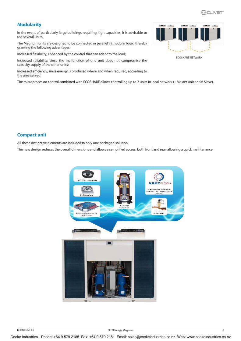
Modularity
In the event of particularly large buildings requiring high capacities, it is advisable to use several units.
The Magnum units are designed to be connected in parallel in modular logic, thereby granting the following advantages:
Increased flexibility, enhanced by the control that can adapt to the load;
Increased reliability, since the malfunction of one unit does not compromise the capacity supply of the other units;
Increased efficiency, since energy is produced where and when required, according to the area served.
The microprocessor control combined with ECOSHARE allows controlling up to 7 units in local network (1 Master unit and 6 Slave).
Compact unit
All these distinctive elements are included in only one packaged solution.
The new design reduces the overall dimensions and allows a semplified access, both front and rear, allowing a quick maintenance.
Cooke Industries - Phone: +64 9 579 2185 Fax: +64 9 579 2181 Email: [email protected] Web: www.cookeindustries.co.nz
10 ELFOEnergy Magnum BT15N007GB-03
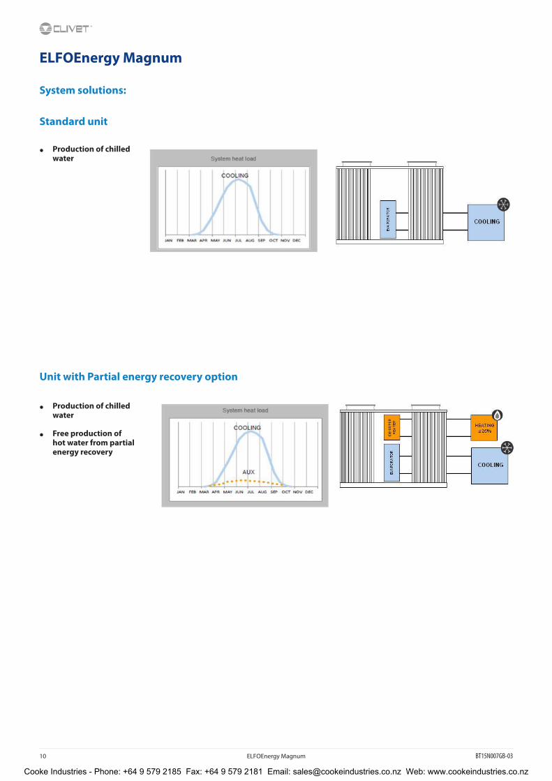
ELFOEnergy Magnum
System solutions:
Standard unit
• Production of chilled water
Unit with Partial energy recovery option
• Production of chilled water
• Free production of hot water from partial energy recovery
Cooke Industries - Phone: +64 9 579 2185 Fax: +64 9 579 2181 Email: [email protected] Web: www.cookeindustries.co.nz
BT15N007GB-03 ELFOEnergy Magnum 11
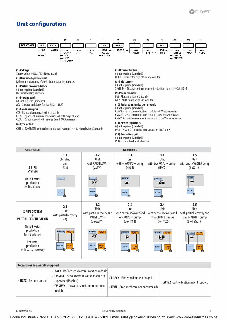
Unit configuration
(1) VoltageSupply voltage 400/3/50+N (standard)(2) User side hydronic unitRefer to the diagrams of the hydronic assembly reported(3) Partial recovery device(-) not required (standard)D - Partial energy recovery(4) Storage tank(-) -not required (standard)ACC - Storage tank (only for size 35.2 ÷ 45.2)(5) Condensing coilCCS - Standard condenser coil (standard)CCCA - Copper / aluminium condenser coil with acrylic liningCCCA1 - Condenser coil with Energy Guard DCC Aluminum(6) Type of fansCREFB - ECOBREEZE external section fans consumption reduction device (Standard)
(7) Diffuser for fan(-) not required (standard)HEDIF - Diffuser for high efficiency axial fan(8) Soft starter(-) not required (standard)SFSTR4N - Disposal for inrush current reduction, for unit 400/3/50+N(9) Phase monitorPM - Phase monitor (standard)MF2 - Multi-function phase monitor(10) Serial communication module(-) not required (standard)CMSC8 - Serial communication module to BACnet supervisorCMSC9 - Serial communication module to Modbus supervisorCMSC10 - Serial communication module to LonWorks supervisor(11) Power capacitors(-) not required (standard)PFCP - Power factor correction capacitors (cosfi > 0.9)(12) Protection grill(-) not required (standard)PGFC - Finned coil protection grill
Functionalities Hydronic units
2 PIPE SYSTEM
Chilled water production
for installation
1.1Standard
unit(Std)
1.2Unit
with VARYFLOW+ (VARYP)
1.3Unit
with one ON/OFF pump(HYG1)
1.4Unit
with two ON/OFF pumps(HYG2)
1.5Unit
with one INVERTER pump(HYGU1V)
2 PIPE SYSTEM+
PARTIAL REGENERATION
Chilled waterproduction
for installation-
Hot water production
with partial recovery
2.1Unit
with partial recovery (D)
2.2Unit
with partial recovery and VARYFLOW+ (D+VARYP)
2.3Unit
with partial recovery and one ON/OFF pump
(D+HYG1)
2.4Unit
with partial recovery and two ON/OFF pumps
(D+HYG2)
2.5Unit
with partial recovery andone INVERTER pump
(D+HYGU1V)
Accessories separately supplied
• RCTX - Remote control
• BACX - BACnet serial communication module• CMMBX - Serial communication module to
supervisor (Modbus)• CMSLWX - LonWorks serial communication
module
• PGFCX - Finned coil protection grill
• IFWX - Steel mesh strainer on water side• AVIBX - Anti-vibration mount support
Cooke Industries - Phone: +64 9 579 2185 Fax: +64 9 579 2181 Email: [email protected] Web: www.cookeindustries.co.nz
12 ELFOEnergy Magnum BT15N007GB-03
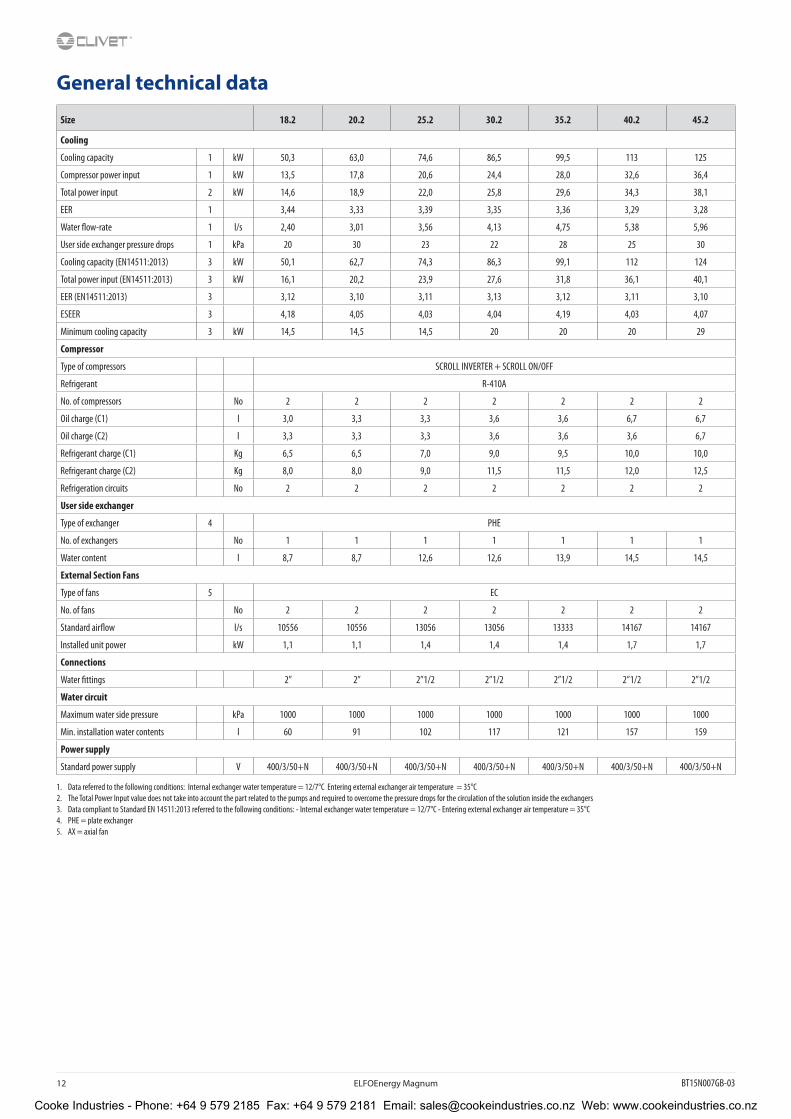
General technical data
Size 18.2 20.2 25.2 30.2 35.2 40.2 45.2
Cooling
Cooling capacity 1 kW 50,3 63,0 74,6 86,5 99,5 113 125
Compressor power input 1 kW 13,5 17,8 20,6 24,4 28,0 32,6 36,4
Total power input 2 kW 14,6 18,9 22,0 25,8 29,6 34,3 38,1
EER 1 3,44 3,33 3,39 3,35 3,36 3,29 3,28
Water flow-rate 1 l/s 2,40 3,01 3,56 4,13 4,75 5,38 5,96
User side exchanger pressure drops 1 kPa 20 30 23 22 28 25 30
Cooling capacity (EN14511:2013) 3 kW 50,1 62,7 74,3 86,3 99,1 112 124
Total power input (EN14511:2013) 3 kW 16,1 20,2 23,9 27,6 31,8 36,1 40,1
EER (EN14511:2013) 3 3,12 3,10 3,11 3,13 3,12 3,11 3,10
ESEER 3 4,18 4,05 4,03 4,04 4,19 4,03 4,07
Minimum cooling capacity 3 kW 14,5 14,5 14,5 20 20 20 29
Compressor
Type of compressors SCROLL INVERTER + SCROLL ON/OFF
Refrigerant R-410A
No. of compressors No 2 2 2 2 2 2 2
Oil charge (C1) l 3,0 3,3 3,3 3,6 3,6 6,7 6,7
Oil charge (C2) l 3,3 3,3 3,3 3,6 3,6 3,6 6,7
Refrigerant charge (C1) Kg 6,5 6,5 7,0 9,0 9,5 10,0 10,0
Refrigerant charge (C2) Kg 8,0 8,0 9,0 11,5 11,5 12,0 12,5
Refrigeration circuits No 2 2 2 2 2 2 2
User side exchanger
Type of exchanger 4 PHE
No. of exchangers No 1 1 1 1 1 1 1
Water content l 8,7 8,7 12,6 12,6 13,9 14,5 14,5
External Section Fans
Type of fans 5 EC
No. of fans No 2 2 2 2 2 2 2
Standard airflow l/s 10556 10556 13056 13056 13333 14167 14167
Installed unit power kW 1,1 1,1 1,4 1,4 1,4 1,7 1,7
Connections
Water fittings 2” 2” 2”1/2 2”1/2 2”1/2 2”1/2 2”1/2
Water circuit
Maximum water side pressure kPa 1000 1000 1000 1000 1000 1000 1000
Min. installation water contents l 60 91 102 117 121 157 159
Power supply
Standard power supply V 400/3/50+N 400/3/50+N 400/3/50+N 400/3/50+N 400/3/50+N 400/3/50+N 400/3/50+N
1. Data referred to the following conditions: Internal exchanger water temperature = 12/7°C Entering external exchanger air temperature = 35°C2. The Total Power Input value does not take into account the part related to the pumps and required to overcome the pressure drops for the circulation of the solution inside the exchangers3. Data compliant to Standard EN 14511:2013 referred to the following conditions: - Internal exchanger water temperature = 12/7°C - Entering external exchanger air temperature = 35°C4. PHE = plate exchanger5. AX = axial fan
Cooke Industries - Phone: +64 9 579 2185 Fax: +64 9 579 2181 Email: [email protected] Web: www.cookeindustries.co.nz

BT15N007GB-03 ELFOEnergy Magnum 13
Electrical dataSupply voltage 400/3/50+N
Size 18.2 20.2 25.2 30.2 35.2 40.2 45.2
F.L.A. - Full load current at max admissible conditions
F.L.A. - Compressor 1 (ON/OFF) A 16,8 24,3 26,6 30,8 30,8 40,6 40,6
F.L.A. - Compressor 2 (INVERTER) A 20,8 20,8 23,3 29,5 32,1 32,1 40,5
F.L.A. - Single External Fan A 3,9 3,9 3,9 3,9 3,9 3,9 3,9
F.L.A. - Total A 45,5 52,9 57,7 68,1 70,7 80,5 88,9
L.R.A. - Loked rotor amperes
L.R.A. - Compressor 1 (ON/OFF) A 98,0 147 158 197 197 215 215
L.R.A. - Compressor 2 (INVERTER) A 20,8 20,8 23,3 29,5 32,1 32,1 40,5
F.L.I. - Full load power input at max admissible conditions
F.L.I. - Compressor 1 (ON/OFF) kW 9,7 14,6 16,5 18,5 18,5 24,8 24,8
F.L.I. - Compressor 2 (INVERTER) kW 12,7 12,7 14,6 18,0 19,6 19,6 26,7
F.L.I. - Single External Fan kW 2,56 2,56 2,56 2,56 2,56 2,56 2,56
F.L.I. - Total kW 27,5 32,5 36,3 41,6 43,3 49,6 56,6
M.I.C. - Maximum unit starting current
M.I.C - Value A 126,6 175,6 189,1 234,3 237,0 255,0 263,3
M.I.C - With soft start accessory A 77,6 102,1 110,1 135,8 138,4 147,4 155,8
Power supply: 400/3/50 Hz. Voltage variation: max. +/-10%Voltage unbalance between phases: max 2 %For non standard voltage please contact Clivet technical officeUnits are in compliance with the european law CEI EN 60204 and CEI EN 60335.
Sound levelsStandard unit
Size
Sound power level (dB) Sound pressure
level
Sound power levelOctave band (Hz)
63 125 250 500 1000 2000 4000 8000 dB(A) dB(A)
18.2 90 83 78 80 78 72 67 61 65 82
20.2 89 82 80 81 77 72 64 59 65 82
25.2 90 83 80 81 79 74 68 60 66 83
30.2 91 84 82 83 78 75 66 59 66 84
35.2 91 85 82 84 79 74 67 61 68 85
40.2 92 85 83 84 80 75 67 62 68 85
45.2 94 85 83 84 82 77 71 63 69 86
Sound levels refer to units with full load under nominal test conditions.The sound pressure level refers to a distance of 1 meter from the outer surface of the unit operating in open field.Noise levels are determined using the tensiometric method (UNI EN ISO 9614-2)Data referred to the following conditions:internal exchanger water = 12/7°Cambient temperature = 35 °C
Unit with HEDIF - “Diffuser for high efficiency axial fan” option
Size
Sound pressure
level
Sound power level
dB(A) dB(A)
18.2 63 80
20.2 63 80
25.2 64 81
30.2 64 82
35.2 66 83
40.2 66 83
45.2 67 84
Sound levels refer to units with full load under nominal test conditions.The sound pressure level refers to a distance of 1m from the outer surface of the unit operating in an open field.Noise levels are determined using the tensiometric method (UNI EN ISO 9614-2)Data referred to the following conditions:internal exchanger water = 12/7°Cambient temperature = 35 °C
Cooke Industries - Phone: +64 9 579 2185 Fax: +64 9 579 2181 Email: [email protected] Web: www.cookeindustries.co.nz

14 ELFOEnergy Magnum BT15N007GB-03
Operating rangeCooling
Unit equipment with low outdoor temperatures
Minimum outdoor air temperature Operating unit Unit in stand-by*
(fed unit)Unit in storage
(unit not fed)
-11°C
√ standard unit √ standard unit √ standard unit (2)
+2°C-7°C
-10°C
Between –10°C and –15°C √ glycol in an appropriate percentage (1) √ glycol in an appropriate percentage (1)
NOT POSSIBLE
Between –15°C and –18°C√ glycol in an appropriate percentage (1)
X not compatible with Clivet integrated pumping device
√ glycol in an appropriate percentage (1)
X not compatible with Clivet integrated pumping device
Data referred to the following conditions:internal exchanger water = 12/7°C
* consider the unit powered electrically, with active control on pumping units. It is recommended to set a set-point value lower than standard (eco mode)
1. Operating range where the water pumping unit must be powered and always active, or with a periodical activation of the outdoor temperature operating pump to guarantee the correct unit operation.2. Unit without water or conteining water with an appropriate quantity of glycol.
At the unit start-up the water temperature or water with glycol must be inside the operating range indicated in the “Operating range” graph.To know the water freezing temperature at the glycol percetage changing refer to the specific ‘Correction factor for antifreeze solutions’ table.
Air conditions which are at rest are defined as the absence of air flowing towards the unit. Weak winds can induce air to flow through the exchanger and air-levels which can cause a reduction in the operating range. In the presence of predominant winds it is necessary to use suitable windbreak barriers.
Twu [°C] = Internal exchanger outlet water temperatureTae [°C] = External exchanger inlet air temperature
1. Standard unit operating range at full load
2. Operating range where the use of ethylene glycol is mandatory in relation to the temperature of the water at the outlet of the user side exchanger
Cooke Industries - Phone: +64 9 579 2185 Fax: +64 9 579 2181 Email: [email protected] Web: www.cookeindustries.co.nz
BT15N007GB-03 ELFOEnergy Magnum 15
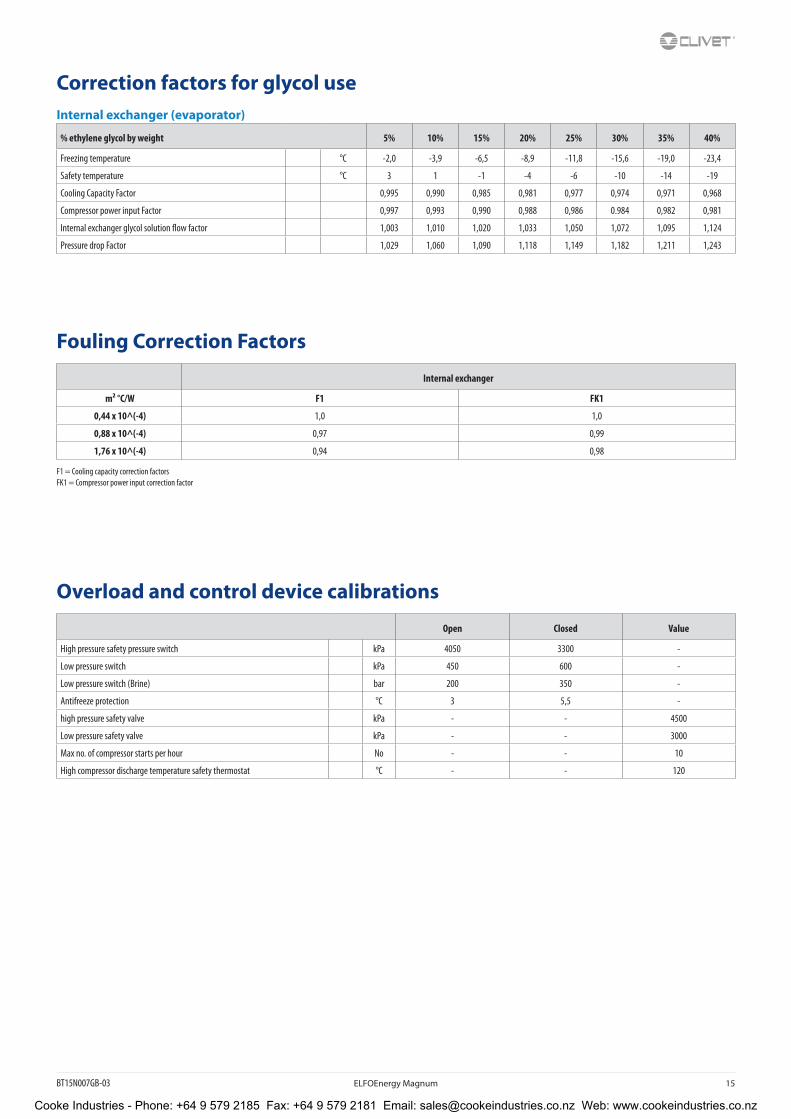
Correction factors for glycol useInternal exchanger (evaporator)
% ethylene glycol by weight 5% 10% 15% 20% 25% 30% 35% 40%
Freezing temperature °C -2,0 -3,9 -6,5 -8,9 -11,8 -15,6 -19,0 -23,4
Safety temperature °C 3 1 -1 -4 -6 -10 -14 -19
Cooling Capacity Factor 0,995 0,990 0,985 0,981 0,977 0,974 0,971 0,968
Compressor power input Factor 0,997 0,993 0,990 0,988 0,986 0.984 0,982 0,981
Internal exchanger glycol solution flow factor 1,003 1,010 1,020 1,033 1,050 1,072 1,095 1,124
Pressure drop Factor 1,029 1,060 1,090 1,118 1,149 1,182 1,211 1,243
Fouling Correction Factors
Internal exchanger
m² °C/W F1 FK1
0,44 x 10^(-4) 1,0 1,0
0,88 x 10^(-4) 0,97 0,99
1,76 x 10^(-4) 0,94 0,98
F1 = Cooling capacity correction factorsFK1 = Compressor power input correction factor
Overload and control device calibrations
Open Closed Value
High pressure safety pressure switch kPa 4050 3300 -
Low pressure switch kPa 450 600 -
Low pressure switch (Brine) bar 200 350 -
Antifreeze protection °C 3 5,5 -
high pressure safety valve kPa - - 4500
Low pressure safety valve kPa - - 3000
Max no. of compressor starts per hour No - - 10
High compressor discharge temperature safety thermostat °C - - 120
Cooke Industries - Phone: +64 9 579 2185 Fax: +64 9 579 2181 Email: [email protected] Web: www.cookeindustries.co.nz
16 ELFOEnergy Magnum BT15N007GB-03
Standard unit technical specifications
CompressorFirst circuit: Hermetic scroll compressor, complete with motor over-temperature and over-current devices and protection against excessive gas discharge temperature. Fitted on rubber antivibration mounts and complete with oil charge. The automatic oil heater prevents the oil from being diluted by the refrigerant when the compressor stops.
Second circuit: Hermetic orbiting scroll compressor, complete with motor over-temperature and over-current devices and protection against excessive gas discharge temperature. Fitted on rubber antivibration mounts and complete with oil charge. The automatic oil heater prevents the oil from being diluted by the refrigerant when the compressor stops.
StructureSupporting structure realised with steel frame with zinc-magnesium superficial traitment painted with polyester powder RAL 9001, that ensures excellent mechanical features and high long-term resilience against corrosion.
PanellingExternal sheet steel panelling with pre-painted zinc-magnesium superficial traitment that ensures superior resistance to corrosion for outdoor installation and eliminates the need for periodical painting. The panels can be easily removed to fully access internal components and are lined with sound-proof material on the inside to contain the unit’s sound levels.
Internal exchangerDirect expansion heat exchanger, braze-welded AISI 316 stainless steel plates with large exchange surface and complete with external heat and anti-condensate insulation.
The exchanger is complete with:
• differential pressure switch, water side
• antifreeze heater to protect the water side exchanger, preventing the formation of frost if the water temperature falls below a set value.
External exchangerDirect expansion finned coil exchanger made with copper pipes placed on staggered rows mechanically expanded to better adhere to the fin collar. The fins are made from aluminium with a corrugated surface and adequately distanced to ensure the maximum heat exchange efficiency.
FanAxial fans with sickle-shaped blades with “Winglets” at the end, coupled directly to a three phase electric external rotor motor with heat protection incorporated, with IP 54 operation. Housed in aerodynamically shaped nozzles to increase efficiency and minimize noise levels. They are fitted with protective safety guard grilles. Supplied with variable speed control (ECOBREEZE).
Refrigeration circuitDouble refrigeration circuit complete, for each circuit, with:
• replaceable anti-acid solid cartridge dehydrator filter
• high pressure safety pressure switch
• high pressure transducer
• low pressure transducer
• refrigerant temperature probe
• electronic thermostatic expansion valve
• high pressure safety valve
Cooke Industries - Phone: +64 9 579 2185 Fax: +64 9 579 2181 Email: [email protected] Web: www.cookeindustries.co.nz

BT15N007GB-03 ELFOEnergy Magnum 17
Electrical panelThe capacity section includes:
• main door lock isolator switch
• isolating transformer for auxiliary circuit power supply
• on-off scroll compressor protection magnetothermic
• inverter scroll compressor protection fuses
• Inverter, complete with thermal protection, for continuous control of the modulating scroll compressor revolutions
• fan protection fuses and heat protection
• on-off scroll compressor control contactor
The control section includes:
• interface terminal with graphic display
• display of the set values, the error codes and the parameter index
• ON/OFF and alarm reset buttons
• proportional-integral water temperature control
• daily, weekly programmer of temperature set-point and unit on/off
• Set point compensation in function of the outdoor air temperature
• set-point compensation with 0-10 V signal
• unit switching on management by local or remote (serial)
• antifreeze protection water side
• compressor overload protection and timer
• prealarm function for water antifreeze and high refrigerant gas pressure
• self-diagnosis system with immediate display of the fault code
• automatic rotation control for compressor starts
• compressor operating hour display
• input for remote ON/OFF control
• relay for remote cumulative fault signal
• inlet for demand limit (power input limitation according to a 0÷10V external signal)
• digital input for double set-point enabling
• potential-free contacts for compressor status
• phase monitor
• ECOSHARE function for the automatic management of a group of units
• numeration of electrical panel cables
Cooke Industries - Phone: +64 9 579 2185 Fax: +64 9 579 2181 Email: [email protected] Web: www.cookeindustries.co.nz

18 ELFOEnergy Magnum BT15N007GB-03
Electronic controlDescription of step start-up controlThe electronic control allows to manage the unit depending on the requested load.
The compressor step activation favours the maximum efficiency and manages at its best the inverter compressor.
The inverter compressor is activated first modulating the capacity in function of the installation return temperature and controlling the supply temperature with PID control.
Main controlsLeaving water temperature control with PID algorithm: it keeps the leaving mean temperature to a set value.
• Auto-adaptive switching on differential: guarantees the compressors minimum operating time in systems with low water content.
• Set point compensation with outdoor temperature
• Condensation control based on pressure
• Pre-alarms at automatic reset: in case of alarm it is allowed a certain number of restarts before the definitive lock.
• Compressor operating hour calculation
• Compressor start calculation
• Control and continuous management of the compressor operating conditions to guarantee the unit operating also in extreme conditions
• Water temperature check (when used) to avoid the pipe freezing
• ”Anti-snow” function: in case of heavy snowfalls, it avoid the deposit of snow on fans
• Alarm log
• Autostart after voltage drop
• Local or remote control
Unit status displayBy the user interface is possible to display:
• unit operating status
• Leaving/entering water temperature
• Outdoor air temperature
• Refrigeration circuit pressure and temperatures (circuit 1 and 2)
• Signalling of alarms and anomalies in progress.
Probe, transducer and parameter displayA user interface dedicated section allows the maintenance or technical assistance personnel to control the unit operating stata.
This section is accessible only by specialized personnel.
Management of more units in cascade (ECOSHARE)It allows the management of several units hydraulically connected up to 1 master and 6 slave maximum.
Units must be of the same type: all reversible heat pumps, or all cool only, or all heat only. Sizes can be different.
The communication among the units is via a BUS serial cable allowing:
• Supply water set-point setting of the slave units
• Setting of logics that increase the system energy efficiency
• Unit operating hours balancing
• Unit management in case of damage (only on slave unit)
• Hydronic assembly switch-off management of units not used
RCTX - Remote controlThe remote control allows the full control of all unit functions from remote position.
It can be easily installed on the wall and has the same aspect and functions of the user interface on the unit.
Cooke Industries - Phone: +64 9 579 2185 Fax: +64 9 579 2181 Email: [email protected] Web: www.cookeindustries.co.nz
BT15N007GB-03 ELFOEnergy Magnum 19
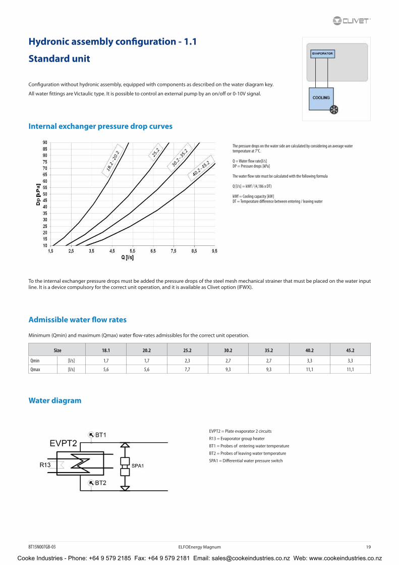
Hydronic assembly configuration - 1.1
Standard unit
Configuration without hydronic assembly, equipped with components as described on the water diagram key.
All water fittings are Victaulic type. It is possible to control an external pump by an on/off or 0-10V signal.
Internal exchanger pressure drop curves
To the internal exchanger pressure drops must be added the pressure drops of the steel mesh mechanical strainer that must be placed on the water input line. It is a device compulsory for the correct unit operation, and it is available as Clivet option (IFWX).
Admissible water flow rates
Minimum (Qmin) and maximum (Qmax) water flow-rates admissibles for the correct unit operation.
Size 18.1 20.2 25.2 30.2 35.2 40.2 45.2
Qmin [l/s] 1,7 1,7 2,3 2,7 2,7 3,3 3,3
Qmax [l/s] 5,6 5,6 7,7 9,3 9,3 11,1 11,1
Water diagram
EVPT2 = Plate evaporator 2 circuits
R13 = Evaporator group heater
BT1 = Probes of entering water temperature
BT2 = Probes of leaving water temperature
SPA1 = Differential water pressure switch
The pressure drops on the water side are calculated by considering an average water temperature at 7°C.
Q = Water flow rate[l/s]DP = Pressure drops [kPa]
The water flow rate must be calculated with the following formula
Q [l/s] = kWf / (4,186 x DT)
kWf = Cooling capacity [kW]DT = Temperature difference between entering / leaving water
Cooke Industries - Phone: +64 9 579 2185 Fax: +64 9 579 2181 Email: [email protected] Web: www.cookeindustries.co.nz
20 ELFOEnergy Magnum BT15N007GB-03
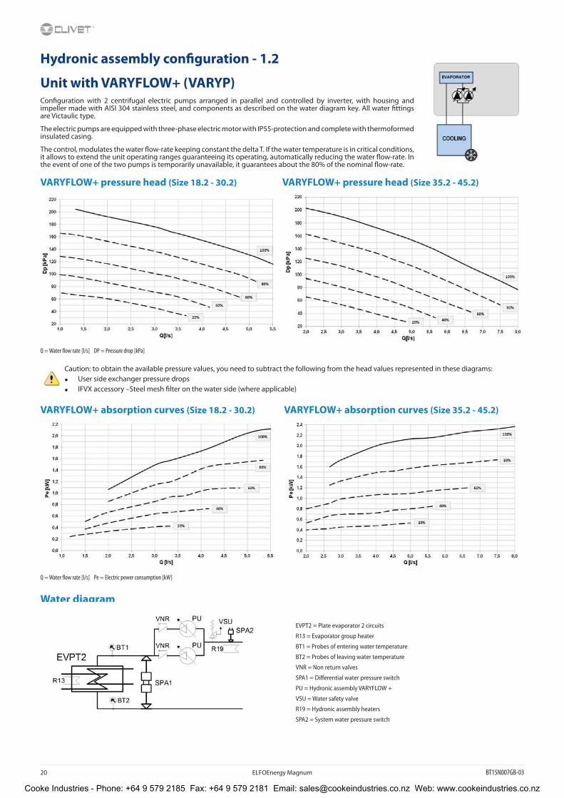
Hydronic assembly configuration - 1.2
Unit with VARYFLOW+ (VARYP)Configuration with 2 centrifugal electric pumps arranged in parallel and controlled by inverter, with housing and impeller made with AISI 304 stainless steel, and components as described on the water diagram key. All water fittings are Victaulic type.
The electric pumps are equipped with three-phase electric motor with IP55-protection and complete with thermoformed insulated casing.
The control, modulates the water flow-rate keeping constant the delta T. If the water temperature is in critical conditions, it allows to extend the unit operating ranges guaranteeing its operating, automatically reducing the water flow-rate. In the event of one of the two pumps is temporarily unavailable, it guarantees about the 80% of the nominal flow-rate.
VARYFLOW+ pressure head (Size 18.2 - 30.2) VARYFLOW+ pressure head (Size 35.2 - 45.2)
Q = Water flow rate [l/s] DP = Pressure drop [kPa]
Caution: to obtain the available pressure values, you need to subtract the following from the head values represented in these diagrams:
• User side exchanger pressure drops
• IFVX accessory –Steel mesh filter on the water side (where applicable)
VARYFLOW+ absorption curves (Size 18.2 - 30.2) VARYFLOW+ absorption curves (Size 35.2 - 45.2)
Q = Water flow rate [l/s] Pe = Electric power consumption [kW]
Water diagram
EVPT2 = Plate evaporator 2 circuits
R13 = Evaporator group heater
BT1 = Probes of entering water temperature
BT2 = Probes of leaving water temperature
VNR = Non return valves
SPA1 = Differential water pressure switch
PU = Hydronic assembly VARYFLOW +
VSU = Water safety valve
R19 = Hydronic assembly heaters
SPA2 = System water pressure switch
Cooke Industries - Phone: +64 9 579 2185 Fax: +64 9 579 2181 Email: [email protected] Web: www.cookeindustries.co.nz
BT15N007GB-03 ELFOEnergy Magnum 21
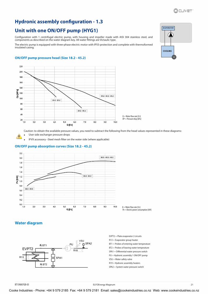
Hydronic assembly configuration - 1.3
Unit with one ON/OFF pump (HYG1)Configuration with 1 centrifugal electric pump, with housing and impeller made with AISI 304 stainless steel, and components as described on the water diagram key. All water fittings are Victaulic type.
The electric pump is equipped with three-phase electric motor with IP55-protection and complete with thermoformed insulated casing.
ON/OFF pump pressure head (Size 18.2 - 45.2)
Caution: to obtain the available pressure values, you need to subtract the following from the head values represented in these diagrams:
• User side exchanger pressure drops
• IFVX accessory –Steel mesh filter on the water side (where applicable)
ON/OFF pump absorption curves (Size 18.2 - 45.2)
Water diagram
EVPT2 = Plate evaporator 2 circuits
R13 = Evaporator group heater
BT1 = Probes of entering water temperature
BT2 = Probes of leaving water temperature
SPA1 = Differential water pressure switch
PU = Hydronic assembly 1 ON/OFF pump
VSU = Water safety valve
R19 = Hydronic assembly heaters
SPA2 = System water pressure switch
Q = Water flow rate [l/s] Pe = Electric power consumption [kW]
Q = Water flow rate [l/s] DP = Pressure drop [kPa]
Cooke Industries - Phone: +64 9 579 2185 Fax: +64 9 579 2181 Email: [email protected] Web: www.cookeindustries.co.nz
22 ELFOEnergy Magnum BT15N007GB-03
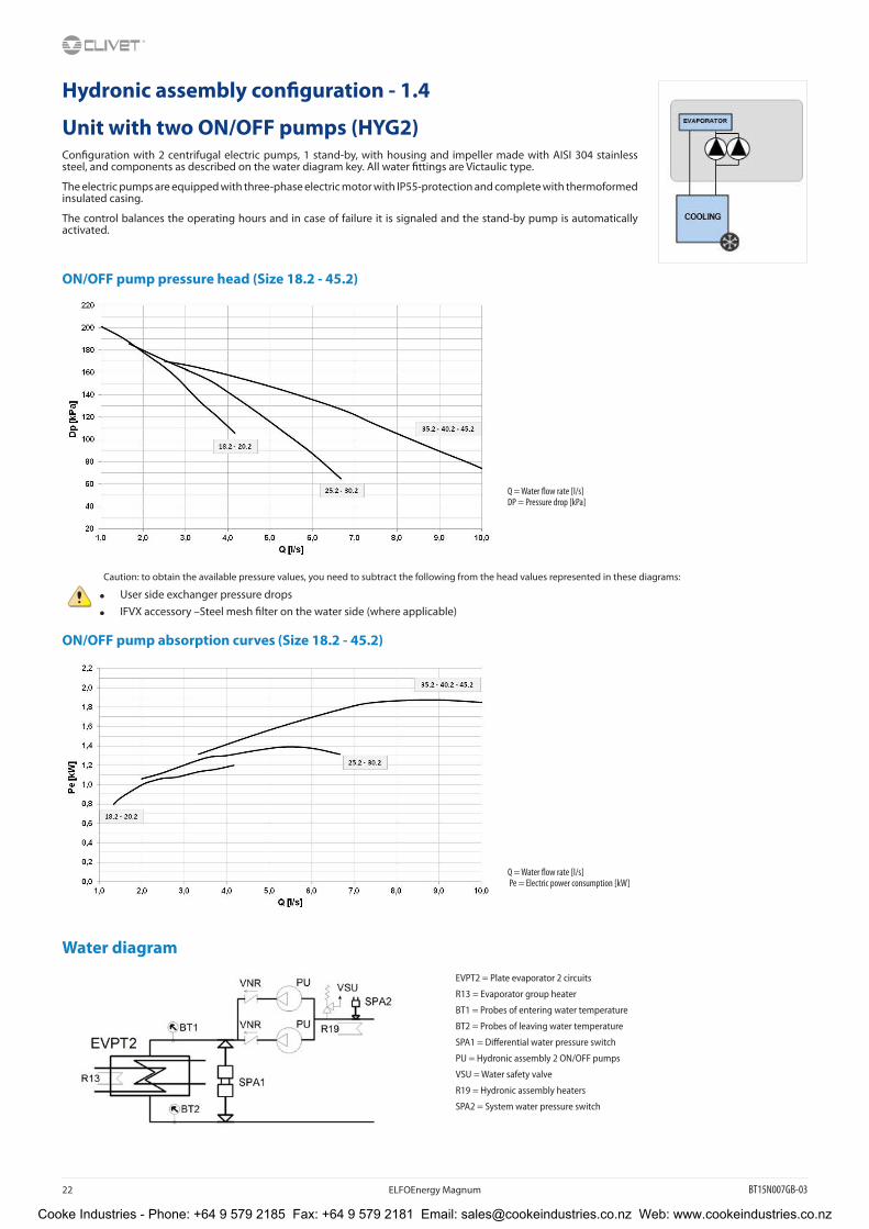
Hydronic assembly configuration - 1.4
Unit with two ON/OFF pumps (HYG2)Configuration with 2 centrifugal electric pumps, 1 stand-by, with housing and impeller made with AISI 304 stainless steel, and components as described on the water diagram key. All water fittings are Victaulic type.
The electric pumps are equipped with three-phase electric motor with IP55-protection and complete with thermoformed insulated casing.
The control balances the operating hours and in case of failure it is signaled and the stand-by pump is automatically activated.
ON/OFF pump pressure head (Size 18.2 - 45.2)
Caution: to obtain the available pressure values, you need to subtract the following from the head values represented in these diagrams:
• User side exchanger pressure drops
• IFVX accessory –Steel mesh filter on the water side (where applicable)
ON/OFF pump absorption curves (Size 18.2 - 45.2)
Water diagram
EVPT2 = Plate evaporator 2 circuits
R13 = Evaporator group heater
BT1 = Probes of entering water temperature
BT2 = Probes of leaving water temperature
SPA1 = Differential water pressure switch
PU = Hydronic assembly 2 ON/OFF pumps
VSU = Water safety valve
R19 = Hydronic assembly heaters
SPA2 = System water pressure switch
Q = Water flow rate [l/s] DP = Pressure drop [kPa]
Q = Water flow rate [l/s] Pe = Electric power consumption [kW]
Cooke Industries - Phone: +64 9 579 2185 Fax: +64 9 579 2181 Email: [email protected] Web: www.cookeindustries.co.nz

BT15N007GB-03 ELFOEnergy Magnum 23
Hydronic assembly configuration - 1.5
Unit with one INVERTER pump (HYGU1V)This configuration provides for one inverter-controlled electric centrifugal pump with body and impeller in AISI 304 steel and components listed in the key of the included water diagram. All water fittings are Victaulic.The electric pump is equipped with three-phase electric motor with IP55-protection and complete with thermoformed insulated casing.
Adjustment enables the optimised load distribution according to the system requirements.
Inverter pump pressure head (Size 18.2 - 20.2) Inverter pump pressure head (Size 25.2 - 30.2)
Q = Water flow rate [l/s] Q = Water flow rate [l/s]DP = Pressure head [kPa] DP = Pressure head [kPa]
Inverter pump absorption curve (Size 18.2 - 20.2) Inverter pump absorption curve (Size 25.2 - 30.2)
Q = Water flow rate [l/s] Q = Water flow rate [l/s]Pe = Electric power consumption [kW] Pe = Electric power consumption [kW]
Cooke Industries - Phone: +64 9 579 2185 Fax: +64 9 579 2181 Email: [email protected] Web: www.cookeindustries.co.nz

24 ELFOEnergy Magnum BT15N007GB-03
Inverter pump available pressure (Size 35.2 - 45.2)
Q = Water flow rate [l/s]DP = Pressure head [kPa]
Inverter pump absorption curve (Size 35.2 - 45.2)
Q = Water flow rate [l/s]Pe = Electric power consumption [kW]
Water diagram
EVPT2 = Plate evaporator 2 circuits
R13 = Evaporator group heater
BT1 = Probes of entering water temperature
BT2 = Probes of leaving water temperature
SPA1 = Differential water pressure switch
PU = Hydronic assembly 1 inverter pump
VSU = Water safety valve
R19 = Hydronic assembly heaters
SPA2 = System water pressure switch
Caution: to obtain the available pressure values, you need to subtract the following from the head values represented in these diagrams:
• User side exchanger pressure drops
• IFVX accessory steel mesh filter on the water side (where applicable)
Cooke Industries - Phone: +64 9 579 2185 Fax: +64 9 579 2181 Email: [email protected] Web: www.cookeindustries.co.nz
BT15N007GB-03 ELFOEnergy Magnum 25
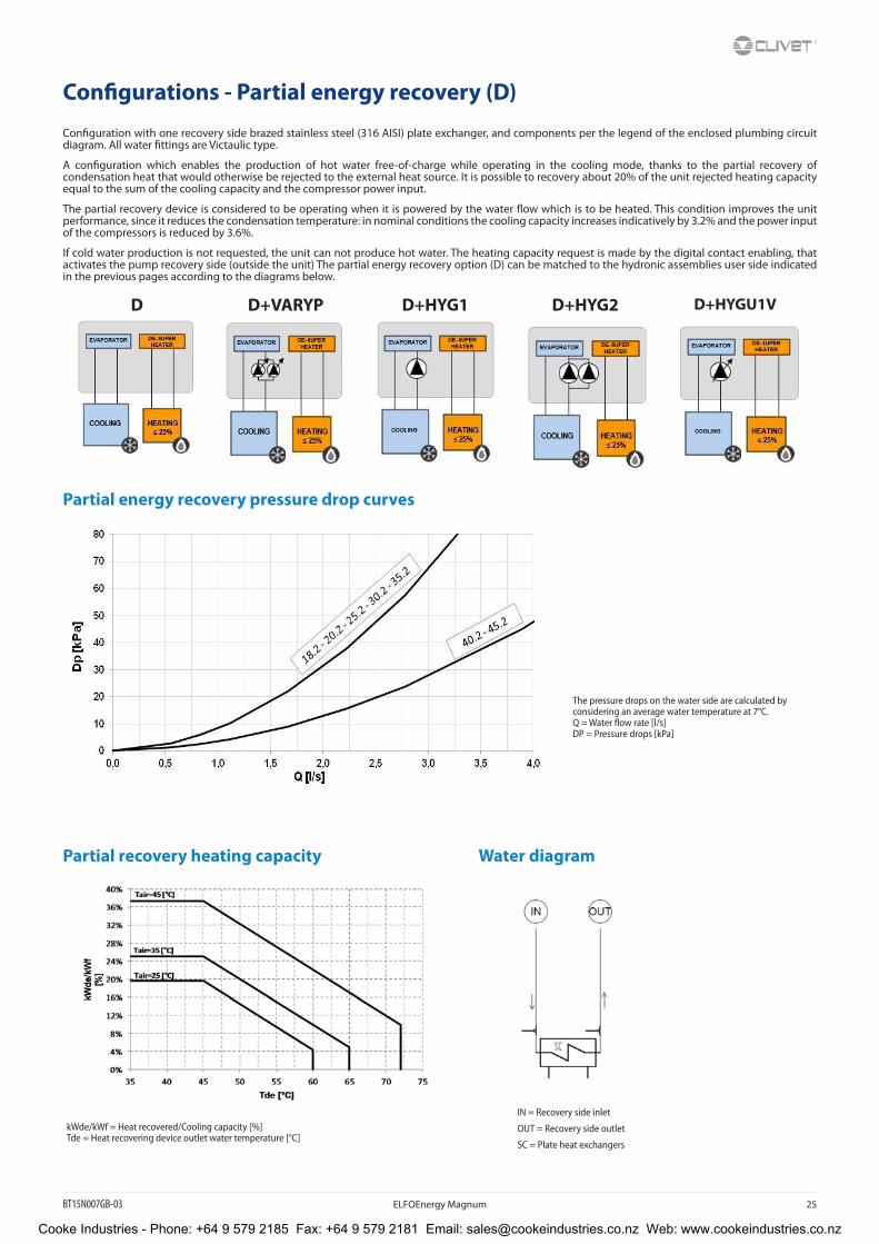
Configurations - Partial energy recovery (D)
Configuration with one recovery side brazed stainless steel (316 AISI) plate exchanger, and components per the legend of the enclosed plumbing circuit diagram. All water fittings are Victaulic type.
A configuration which enables the production of hot water free-of-charge while operating in the cooling mode, thanks to the partial recovery of condensation heat that would otherwise be rejected to the external heat source. It is possible to recovery about 20% of the unit rejected heating capacity equal to the sum of the cooling capacity and the compressor power input.
The partial recovery device is considered to be operating when it is powered by the water flow which is to be heated. This condition improves the unit performance, since it reduces the condensation temperature: in nominal conditions the cooling capacity increases indicatively by 3.2% and the power input of the compressors is reduced by 3.6%.
If cold water production is not requested, the unit can not produce hot water. The heating capacity request is made by the digital contact enabling, that activates the pump recovery side (outside the unit) The partial energy recovery option (D) can be matched to the hydronic assemblies user side indicated in the previous pages according to the diagrams below.
D D+VARYP D+HYG1 D+HYG2 D+HYGU1V
Partial energy recovery pressure drop curves
Partial recovery heating capacity Water diagram
The pressure drops on the water side are calculated by considering an average water temperature at 7°C.Q = Water flow rate [l/s]DP = Pressure drops [kPa]
kWde/kWf = Heat recovered/Cooling capacity [%]Tde = Heat recovering device outlet water temperature [°C]
IN = Recovery side inlet
OUT = Recovery side outlet
SC = Plate heat exchangers
Cooke Industries - Phone: +64 9 579 2185 Fax: +64 9 579 2181 Email: [email protected] Web: www.cookeindustries.co.nz

26 ELFOEnergy Magnum BT15N007GB-03
Built-in configuration options
ACC - Storage tankOption supplied built-in the unit. Steel storage tank complete with double layer covering with closed-cell insulation, stainless steel anti-freeze immersion resistance, bleed valve, draw off cock, quick connections with insulated casing. The various available models can be differentiated by capacity.
Available only for size 35.2 ÷ 45.2.
The storage tank capacity is 150L.
CCCA - Copper / aluminium condenser coil with acrylic liningCoils with copper pipes and aluminium fins with acrylic lining. Resist bi-metallic corrosion and allow for application in coastal areas.
Attention!
• cooling capacity variation -2.7%
• variation in compressor power input +4.2%
• operating range reduction -2.1°C
CCCA1 - Condenser coil with Aluminum Energy Guard DCC treatmentA treatment which offers an optimal thermal exchange and guarantees and protects the finned coil exchangers from corrosion over time. Can be used in settings with very aggressive saline concentrations and other chemical agents in the air thus maintaining the performance of the coils over time.
PFCP - Power factor correction capacitors (cosfi>0,9)The component is necessary to lower the phase difference between current and voltage in the electromagnetic components of the unit (e.g. asynchronous motors). The component allows to put the cosfi power factor to values on average higher than 0.9, reducing the network reactive power. This often leads to an economic benefit which the energy provider grants to the final user.
MF2 - Multi-function phase monitorMultifunction phase monitor supplied as standard: it controls the presence and the correct phase sequences, verifies possible voltage anomalies (-10%), it automatically resets the unit operation, when the correct power supply is re-established
This control allows to:
• protect components inside the unit, as if they are powered by an anomalous voltage they may operate incorrectly or break;
• quickly identify, among the alarms of the unit’s components, the real cause of the malfunction due to the sudden change in voltage.
SFSTR4N - Disposal for inrush current reduction, for unit 400/3/50+NElectronic device that automatically and gradually starts the compressors, thereby reducing the current peak generated in star-triangle start-ups and therefore reduces the mechanical stress on the motor and the electrodynamic stress on the power cables and on the mains.
PGFC – Finned coil protection grillThis accessory is used to protect the external coil from the accidental contact with external things or people.Ideal for installation in places where persons can pass from, such as car parks, terraces, etc.
HEDIF - Diffuser for high efficiency axial fanThe new AxiTop diffuser creates an ideal air distribution: it aerodynamically decelerates the flow and transforms a big part of its kinetic energy in static pressure. Obtaining:
• down to –3 dB of silence
• reduction of 3% of the absorbed energy
Since the fans are the unit’s main noise source, the benefits are evident especially during the night hours, when the load is reduced but sensitivity to noise is enhanced.
Cooke Industries - Phone: +64 9 579 2185 Fax: +64 9 579 2181 Email: [email protected] Web: www.cookeindustries.co.nz

BT15N007GB-03 ELFOEnergy Magnum 27
CMSC8 - Serial communication module to BACnet supervisorAllows the serial connection to supervision systems by using BACnet-IP as a communication protocol. It allows the access to the entire list of operating variables, controls and alarms. With this accessory every unit can communicate with the main supervision systems.
The device is built-in the unit.
The configuration and management activities for the BACnet networks are the responsibility of the client.
The total length of each serial line do not exceed 1000 meters and the line must be connected in bus typology (in/out)
CMSC9 - Serial communication module to Modbus supervisorThis enables the serial connection of the supervision system, using Modbus as the communication protocol. It enables access to the complete list of operational variables, commands and alarms. Using this accessory every unit can dialogue with the main supervision systems.
The device is built-in the unit.
The total length of each serial line do not exceed 1000 meters and the line must be connected in bus typology (in/out)
CMSC10 - Serial communication module to LonWorks supervisorThis enables the serial connection of the supervision system which uses the LonWorks communication protocol. It enables access to a list of operating variables, commands and alarms which comply with the Echelon® standard.
The device is built-in the unit.
The configuration and management activities for the LonWorks networks are the responsibility of the client.
LonWorks technology uses the LonTalk® protocol for communicating between the network nodes. Contact the service supplier for further information.
Cooke Industries - Phone: +64 9 579 2185 Fax: +64 9 579 2181 Email: [email protected] Web: www.cookeindustries.co.nz

28 ELFOEnergy Magnum BT15N007GB-03
Accessories separately supplied
RCTX - Remote controlThis option allows to have full control over all the unit functions from a remote position. It can be easily installed on the wall and has the same aspect and functions of the user interface on the unit.
All device functions can be repeated with a normal portable PC connected to the unit with an Ethernet cable and equipped with an internet navigation browser.
The device should be installed on the wall using suitable plugs, electrically hooked up and connected to the unit (installation and wiring are the responsibility of the Customer). Max. remote distance 350 m without auxiliary supply.
Data and power supply serial connection cable n.1 twisted and shielded pair. Diameter of the individual conductor 0.8 mm.
Installation provided by the Customer.
BACX - BACnet serial communication moduleAllows the serial connection to supervision systems by using BACnet-IP as a communication protocol. It allows the access to the entire list of operating variables, controls and alarms. With this accessory every unit can communicate with the main supervision systems.
The configuration and management activities for the BACnet networks are the responsibility of the client.
The total length of each serial line do not exceed 1000 meters and the line must be connected in bus typology (in/out)
Installation provided by the Customer.
CMMBX - Serial communication module to supervisor (Modbus)This enables the serial connection of the supervision system, using Modbus as the communication protocol. It enables access to the complete list of operational variables, commands and alarms. Using this accessory every unit can dialogue with the main supervision systems.
The device is installed and wired built-in the unit.
The total length of each serial line do not exceed 1000 meters and the line must be connected in bus typology (in/out)
Installation provided by the Customer.
CMSLWX - LonWorks serial communication moduleThis enables the serial connection of the supervision system which uses the LonWorks communication protocol. It enables access to a list of operating variables, commands and alarms which comply with the Echelon® standard.
The device is installed and wired built-in the unit.
The configuration and management activities for the LonWorks networks are the responsibility of the client.
LonWorks technology uses the LonTalk® protocol for communicating between the network nodes. Contact the service supplier for further information.
Installation provided by the Customer.
PGFCX - Finned coil protection grillThis accessory is used to protect the external coil from the accidental contact with external things or people. Ideal for installation in places where persons can pass from, such as car parks, terraces, etc. The accessory is supplied installed built-in the unit.
This option is not suitable for application in sulphuric environments
Installation provided by the Customer.
Cooke Industries - Phone: +64 9 579 2185 Fax: +64 9 579 2181 Email: [email protected] Web: www.cookeindustries.co.nz
BT15N007GB-03 ELFOEnergy Magnum 29
AVIBX - Anti-vibration mount supportThe rubber antivibration mounts are attached in special housing on the support frame and serve to smooth the vibrations produced by the unit thus reducing the noise transmitted to the support structure.
Installation provided by the Customer.
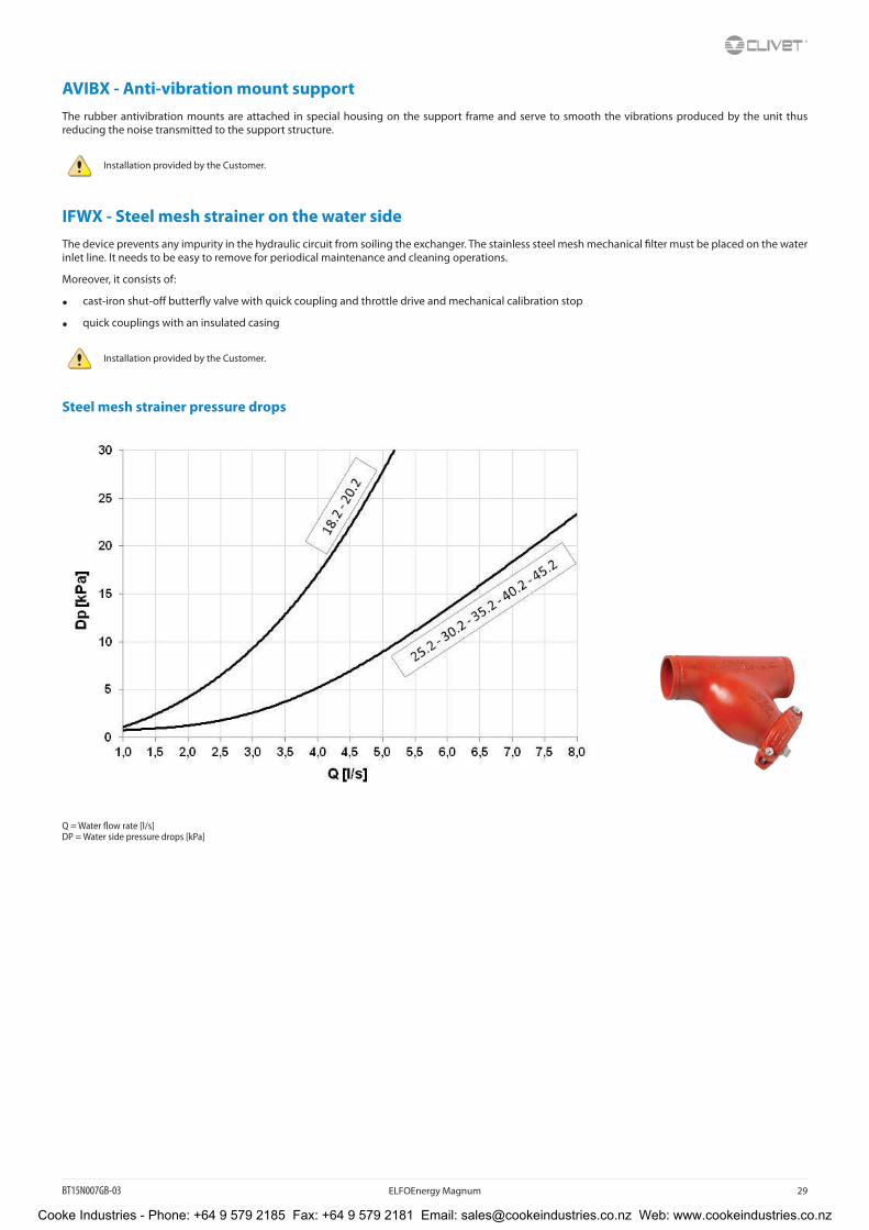
IFWX - Steel mesh strainer on the water sideThe device prevents any impurity in the hydraulic circuit from soiling the exchanger. The stainless steel mesh mechanical filter must be placed on the water inlet line. It needs to be easy to remove for periodical maintenance and cleaning operations.
Moreover, it consists of:
• cast-iron shut-off butterfly valve with quick coupling and throttle drive and mechanical calibration stop
• quick couplings with an insulated casing
Installation provided by the Customer.
Steel mesh strainer pressure drops
Q = Water flow rate [l/s]DP = Water side pressure drops [kPa]
Cooke Industries - Phone: +64 9 579 2185 Fax: +64 9 579 2181 Email: [email protected] Web: www.cookeindustries.co.nz
30 ELFOEnergy Magnum BT15N007GB-03
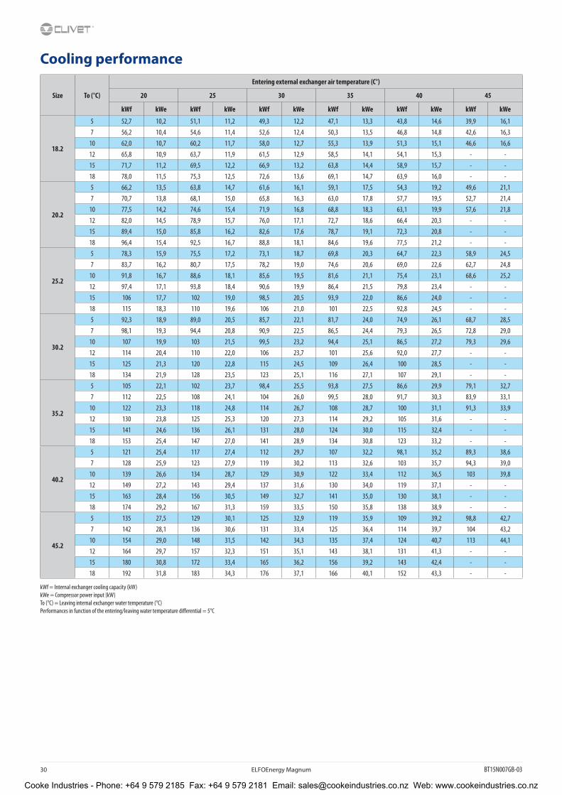
Cooling performance
Size To (°C)
Entering external exchanger air temperature (C°)
20 25 30 35 40 45
kWf kWe kWf kWe kWf kWe kWf kWe kWf kWe kWf kWe
18.2
5 52,7 10,2 51,1 11,2 49,3 12,2 47,1 13,3 43,8 14,6 39,9 16,17 56,2 10,4 54,6 11,4 52,6 12,4 50,3 13,5 46,8 14,8 42,6 16,3
10 62,0 10,7 60,2 11,7 58,0 12,7 55,3 13,9 51,3 15,1 46,6 16,612 65,8 10,9 63,7 11,9 61,5 12,9 58,5 14,1 54,1 15,3 - -15 71,7 11,2 69,5 12,2 66,9 13,2 63,8 14,4 58,9 15,7 - -18 78,0 11,5 75,3 12,5 72,6 13,6 69,1 14,7 63,9 16,0 - -
20.2
5 66,2 13,5 63,8 14,7 61,6 16,1 59,1 17,5 54,3 19,2 49,6 21,17 70,7 13,8 68,1 15,0 65,8 16,3 63,0 17,8 57,7 19,5 52,7 21,4
10 77,5 14,2 74,6 15,4 71,9 16,8 68,8 18,3 63,1 19,9 57,6 21,812 82,0 14,5 78,9 15,7 76,0 17,1 72,7 18,6 66,4 20,3 - -15 89,4 15,0 85,8 16,2 82,6 17,6 78,7 19,1 72,3 20,8 - -18 96,4 15,4 92,5 16,7 88,8 18,1 84,6 19,6 77,5 21,2 - -
25.2
5 78,3 15,9 75,5 17,2 73,1 18,7 69,8 20,3 64,7 22,3 58,9 24,57 83,7 16,2 80,7 17,5 78,2 19,0 74,6 20,6 69,0 22,6 62,7 24,8
10 91,8 16,7 88,6 18,1 85,6 19,5 81,6 21,1 75,4 23,1 68,6 25,212 97,4 17,1 93,8 18,4 90,6 19,9 86,4 21,5 79,8 23,4 - -15 106 17,7 102 19,0 98,5 20,5 93,9 22,0 86,6 24,0 - -18 115 18,3 110 19,6 106 21,0 101 22,5 92,8 24,5 - -
30.2
5 92,3 18,9 89,0 20,5 85,7 22,1 81,7 24,0 74,9 26,1 68,7 28,57 98,1 19,3 94,4 20,8 90,9 22,5 86,5 24,4 79,3 26,5 72,8 29,0
10 107 19,9 103 21,5 99,5 23,2 94,4 25,1 86,5 27,2 79,3 29,612 114 20,4 110 22,0 106 23,7 101 25,6 92,0 27,7 - -15 125 21,3 120 22,8 115 24,5 109 26,4 100 28,5 - -18 134 21,9 128 23,5 123 25,1 116 27,1 107 29,1 - -
35.2
5 105 22,1 102 23,7 98,4 25,5 93,8 27,5 86,6 29,9 79,1 32,77 112 22,5 108 24,1 104 26,0 99,5 28,0 91,7 30,3 83,9 33,1
10 122 23,3 118 24,8 114 26,7 108 28,7 100 31,1 91,3 33,912 130 23,8 125 25,3 120 27,3 114 29,2 105 31,6 - -15 141 24,6 136 26,1 131 28,0 124 30,0 115 32,4 - -18 153 25,4 147 27,0 141 28,9 134 30,8 123 33,2 - -
40.2
5 121 25,4 117 27,4 112 29,7 107 32,2 98,1 35,2 89,3 38,67 128 25,9 123 27,9 119 30,2 113 32,6 103 35,7 94,3 39,0
10 139 26,6 134 28,7 129 30,9 122 33,4 112 36,5 103 39,812 149 27,2 143 29,4 137 31,6 130 34,0 119 37,1 - -15 163 28,4 156 30,5 149 32,7 141 35,0 130 38,1 - -18 174 29,2 167 31,3 159 33,5 150 35,8 138 38,9 - -
45.2
5 135 27,5 129 30,1 125 32,9 119 35,9 109 39,2 98,8 42,77 142 28,1 136 30,6 131 33,4 125 36,4 114 39,7 104 43,2
10 154 29,0 148 31,5 142 34,3 135 37,4 124 40,7 113 44,112 164 29,7 157 32,3 151 35,1 143 38,1 131 41,3 - -15 180 30,8 172 33,4 165 36,2 156 39,2 143 42,4 - -18 192 31,8 183 34,3 176 37,1 166 40,1 152 43,3 - -
kWf = Internal exchanger cooling capacity (kW)kWe = Compressor power input (kW)To (°C) = Leaving internal exchanger water temperature (°C)Performances in function of the entering/leaving water temperature differential = 5°C
Cooke Industries - Phone: +64 9 579 2185 Fax: +64 9 579 2181 Email: [email protected] Web: www.cookeindustries.co.nz

BT15N007GB-03 ELFOEnergy Magnum 31
Dimensional drawingsSize 18.2 - 20.2
1. Water inlet user side Ø 2” Victaulic
2. Water outlet user side Ø 2” Victaulic
3. Water inlet recovery side Ø 1” 1/4 Victaulic (optional)
4. Water outlet recovery side Ø 1” 1/4 Victaulic (optional)
5. General electrical panel
6. Compressor compartment
7. Power input
8. Lifting brackets (removable)
9. Unit fixing holes Ø 18mm
10. Clearance access recommended
Size 18.2 20.2
A - Length mm 2400 2400
B - Width mm 1100 1100
C - Standard unit height mm 1540 1540
C - Height with HEDIF option mm 1690 1690
W1 Supporting Point kg 160 164
W2 Supporting Point kg 157 161
W3 Supporting Point kg 135 136
W4 Supporting Point kg 133 134
Operating weight kg 575 595
Shipping weight kg 580 585
The presence of optional accessories may result in a substantial variation of the weights shown in the table.
DABM218.2_20.2_027/01/2016
Cooke Industries - Phone: +64 9 579 2185 Fax: +64 9 579 2181 Email: [email protected] Web: www.cookeindustries.co.nz

32 ELFOEnergy Magnum BT15N007GB-03
Dimensional drawingsSize 25.2 - 30.2
1. Water inlet user side Ø 2” 1/2 Victaulic
2. Water outlet user side Ø 2” 1/2 Victaulic
3. Water inlet recovery side Ø 1” 1/4 Victaulic (optional)
4. Water outlet recovery side Ø 1” 1/4 Victaulic (optional)
5. General electrical panel
6. Compressor compartment
7. Power input
8. Lifting brackets (removable)
9. Unit fixing holes Ø 18mm
10. Clearance access recommended
Size 25.2 30.2
A - Length mm 2400 2400
B - Width mm 1100 1100
C - Standard unit height mm 1790 1790
C - Height with HEDIF option mm 1940 1940
W1 Supporting Point kg 180 196
W2 Supporting Point kg 180 194
W3 Supporting Point kg 137 144
W4 Supporting Point kg 137 142
Operating weight kg 634 676
Shipping weight kg 620 661
The presence of optional accessories may result in a substantial variation of the weights shown in the table.
DABM225.2_30.2_017/12/2015
Cooke Industries - Phone: +64 9 579 2185 Fax: +64 9 579 2181 Email: [email protected] Web: www.cookeindustries.co.nz

BT15N007GB-03 ELFOEnergy Magnum 33
Dimensional drawingsSize 35.2 - 40.2 - 45.2
1. Water inlet user side Ø 2” 1/2 Victaulic
2. Water outlet user side Ø 2” 1/2 Victaulic
3. Water inlet recovery side Ø 1” 1/2 Victaulic
4. Water outlet recovery side Ø 1” 1/2 Victaulic
5. General electrical panel
6. Compressor compartment
7. Power input
8. Lifting brackets (removable)
9. Unit fixing holes Ø 18mm
10. Clearance access recommended
Size 35.2 40.2 45.2
A - Length mm 3600 3600 3600
B - Width mm 1100 1100 1100
C - Standard unit height mm 1890 1890 1890
C - Height with HEDIF option mm 2040 2040 2040
W1 Supporting Point kg 183 195 205
W2 Supporting Point kg 184 193 207
W3 Supporting Point kg 223 237 254
W4 Supporting Point kg 223 235 257
Operating weight kg 813 860 923
Shipping weight kg 802 849 913
The presence of optional accessories may result in a substantial variation of the weights shown in the table.
DABM235.2_40.2_45.2_014/09/2015
Cooke Industries - Phone: +64 9 579 2185 Fax: +64 9 579 2181 Email: [email protected] Web: www.cookeindustries.co.nz

34 ELFOEnergy Magnum BT15N007GB-03
Page intentionally left blank
Cooke Industries - Phone: +64 9 579 2185 Fax: +64 9 579 2181 Email: [email protected] Web: www.cookeindustries.co.nz

BT15N007GB-03 ELFOEnergy Magnum 35
Page intentionally left blank
Cooke Industries - Phone: +64 9 579 2185 Fax: +64 9 579 2181 Email: [email protected] Web: www.cookeindustries.co.nz
CLIVET SPAVia Camp Lonc 25, Z.I. Villapaiera - 32032 Feltre (BL) - Italy Tel. + 39 0439 3131 - Fax + 39 0439 313300 - [email protected]
CLIVET UK LTD (Sales)4 Kingdom Close, Segensworth East - Fareham, Hampshire - PO15 5TJ - United KingdomTel. + 44 (0) 1489 572238 - Fax + 44 (0) 1489 573033 - [email protected]
CLIVET AIRCON LTD (Service and Maintenance Division)Units F5&F6 Railway Triangle Ind Est, Walton Road - Portsmouth, Hampshire - PO6 1TG - United KingdomTel. +44 (0) 2392 381235 - Fax. +44 (0) 2392 381243 - [email protected]
CLIVET ESPAÑA COMERCIAL S.L. (Sales)Calle Gurb, 17 1º 1ª - 08500 Vic, Barcelona - EspañaTel: +34 93 8606248 - Fax +34 93 8855392 - [email protected]
CLIVET ESPAÑA S.A.U. (Service and Maintenance Division)Calle Real de Burgos Nº 12 - 28860 Paracuellos del Jarama, Madrid - EspañaTel. +34 91 6658280 - Fax +34 91 6657806 - [email protected]
CLIVET GmbH (Hydronic and Applied Division)Hummelsbütteler Steindamm 84, 22851 Norderstedt - GermanyTel. + 49 (0) 40 32 59 57-0 - Fax + 49 (0) 40 32 59 57-194 - [email protected]
CLIVET GmbH (VRF, Residential and Lightcom Division)Eisenstrasse 9c, 65428 Rüsselsheim/Frankfurt - GermanyTel. + 49 (0) 6142 83594-0 - Fax + 49 (0) 6142 83594-20 - [email protected]
CLIVET RUSSIA Elektrozavodskaya st. 24, office 509 - 107023, Moscow, RussiaTel. + 74956462009 - Fax + 74956462009 - [email protected]
CLIVET MIDEAST FZCODubai Silicon Oasis (DSO), High Bay Complex, Office N. 20, PO BOX 342009, Dubai, UAE Tel. + 9714 3208499 - Fax + 9714 3208216 - [email protected]
CLIVET AIRCONDITIONING SYSTEMS PRIVATE LIMITED4BA, Gundecha Onclave, Kherani Road - Sakinaka, Andheri (East) - Mumbai 400 072 - IndiaTel. +91 22 6193 7000 - Fax +91 22 6193 7001 - [email protected]
w w w . c l i v e t . c o mw w w.cl ivet l ive.com
A Group Company of
Cooke Industries - Phone: +64 9 579 2185 Fax: +64 9 579 2181 Email: [email protected] Web: www.cookeindustries.co.nz