
Elevator/Escalator Health and Safety Manual - IHSA€¦ · Elevator/Escalator Trade...
38
ELEVATOR/ESCALATOR HEALTH AND SAFETY MANUAL © Construction Safety Association of Ontario, September 2008 Prepared for the Elevator/Escalator Trade Labour-Management Health and Safety Committee
Transcript of Elevator/Escalator Health and Safety Manual - IHSA€¦ · Elevator/Escalator Trade...
ELEVATOR/ESCALATOR HEALTH AND SAFETY
MANUAL
© Construction Safety Association of Ontario, September 2008
Prepared for the Elevator/Escalator Trade
Labour-Management Health and Safety Committee
Construction Safety Association of Ontario 1-800-781-2726 www.csao.org 2
CONTENTS
Fall protection guidelines for elevator construction 3 Hoisting with a capstan 20 Tuggers (powered winches) 28 Well wheels (gin wheels) for light hoisting 31
Construction Safety Association of Ontario 1-800-781-2726 www.csao.org 3
FALL PROTECTION GUIDELINES for
ELEVATOR CONSTRUCTION
Construction Safety Association of Ontario 1-800-781-2726 www.csao.org 4
Construction Safety Association of Ontario 1-800-781-2726 www.csao.org 5
Fall protection guidelines for elevator construction
INTRODUCTION These guidelines are intended to describe basic fall protection procedures for elevator construction. They are not intended to describe the elevator construction process or the specific requirements for various types, designs, or manufacturers. DEFINITIONS Fall arrest system: An assembly of components joined together so that when the assembly is connected to a fixed support, it is capable of arresting a worker’s fall. Fall restricting system: A type of fall-arrest system that has been designed to limit a worker’s fall to a specified distance. Travel restraint system: An assembly of components capable of restricting a worker’s movement on a work surface and preventing the worker from reaching a location from which the worker could fall. Vertical lifeline: A rope or wire that is attached to an anchor. The lanyard of a fall-arrest system is attached to the lifeline. The lifeline extends the reach of the lanyard to an appropriate anchor point. An example of a lifeline is a 5/8" diameter synthetic rope (polypropylene blend) with a spliced loop and thimble for attachment to an anchor point using a shackle. It must extend to the ground or the lowest point that a worker could access. If synthetic rope may be subjected to damage such as from welding or cutting operations, a CSA-approved 3/8" diameter
wire-rope lifeline may be used, provided a CSA approved rope grab that is matched to the wire rope is also used.
Exposure to the sun may damage or weaken synthetic lifelines. Ensure that material being considered for lifelines is UV-resistant. There must be a separate lifeline for each worker using a fall-arrest system. Anchor point (for a vertical lifeline): A structure, or a device attached to a structure, which will support a fall-arrest load. A support used in a fall-arrest system must be capable of supporting a static force of at least 8 kilonewtons (1800 lb) without exceeding the allowable unit stress for each material used. Horizontal lifeline: A horizontal lifeline is a
lifeline connected horizontally with an anchor point at each end. Because of its configuration, it may have very high end
A vertical lifeline must meet CAN/CSA-Z259.2.1-98 standard Fall Arresting Devices and Vertical Lifelines. Vertical lifelines sold on a reel or in a container will have the CSA standard information attached or etched on the container or reel. Once removed from the original packaging, pertinent information such as the purchase order number and CSA certification should be identified on the lifeline (with tags or otherwise) to ensure it does not get confused with hoisting rope and cable. The lifeline should be stored separately from hoisting ropes and cable.
Construction Safety Association of Ontario 1-800-781-2726 www.csao.org 6
loads in the event of a fall arrest. Horizontal lifelines, including the end anchorages, must be designed by a professional engineer. FALL PROTECTION TRAINING The Construction Regulation (Ontario Regulation 213/91) requires • that employers ensure that workers using
a fall protection system are trained in its use
• that training records are kept, including training dates and participants’ names
• that employers have training records available for Ministry of Labour inspectors upon request.
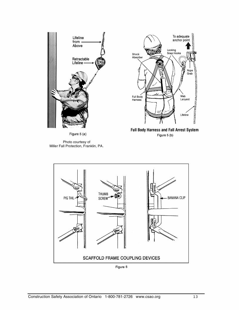
RESCUE PROCEDURES Before use of a fall-arrest system or a safety net by a worker on a project, the worker’s employer must develop written procedures for rescuing the worker in the event of a fall arrest. Minimizing the time between a fall occurrence and medical attention is vitally important. INSPECTION All fall protection equipment must be inspected for damage, wear, and obvious defects by a competent worker before each use. Any defective component must be replaced by one that meets or exceeds the manufacturer’s minimum performance standards for that particular system. FALL ARREST SYSTEMS Depending on the application, a fall-arrest system typically consists of a full body harness, shock absorber, and lanyard as specified above, attached to an adequate anchor point. Anchorages for the system should be designed by a professional engineer and a sketch stamped by the engineer should be
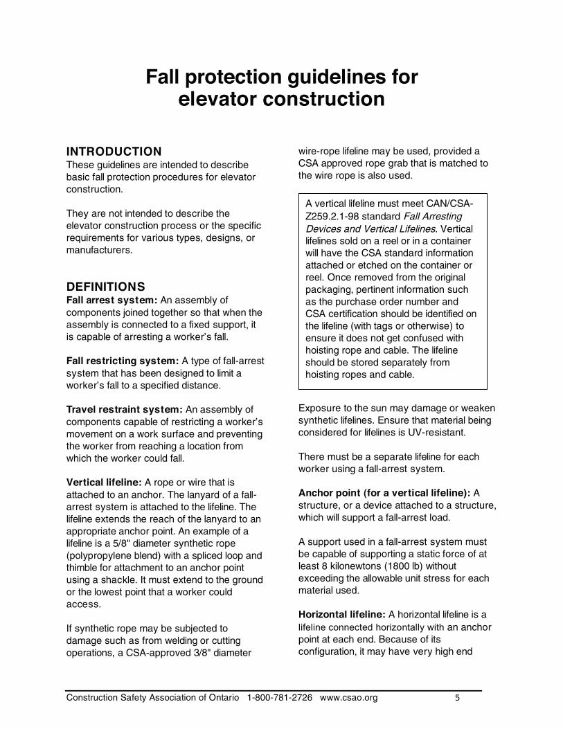
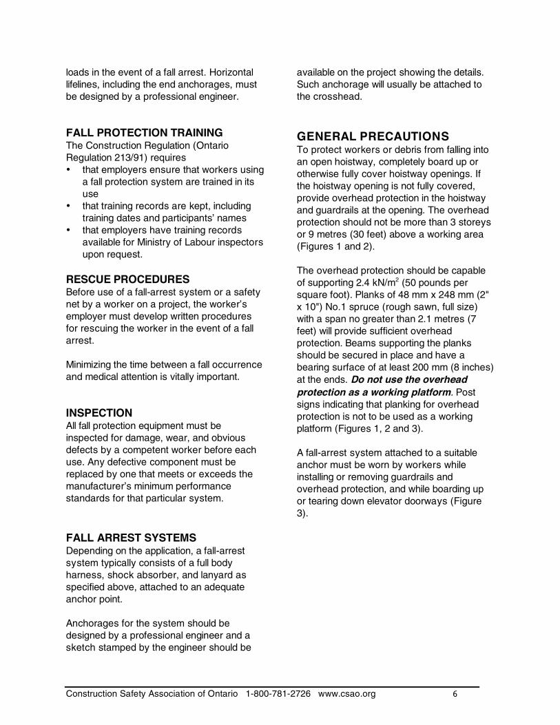
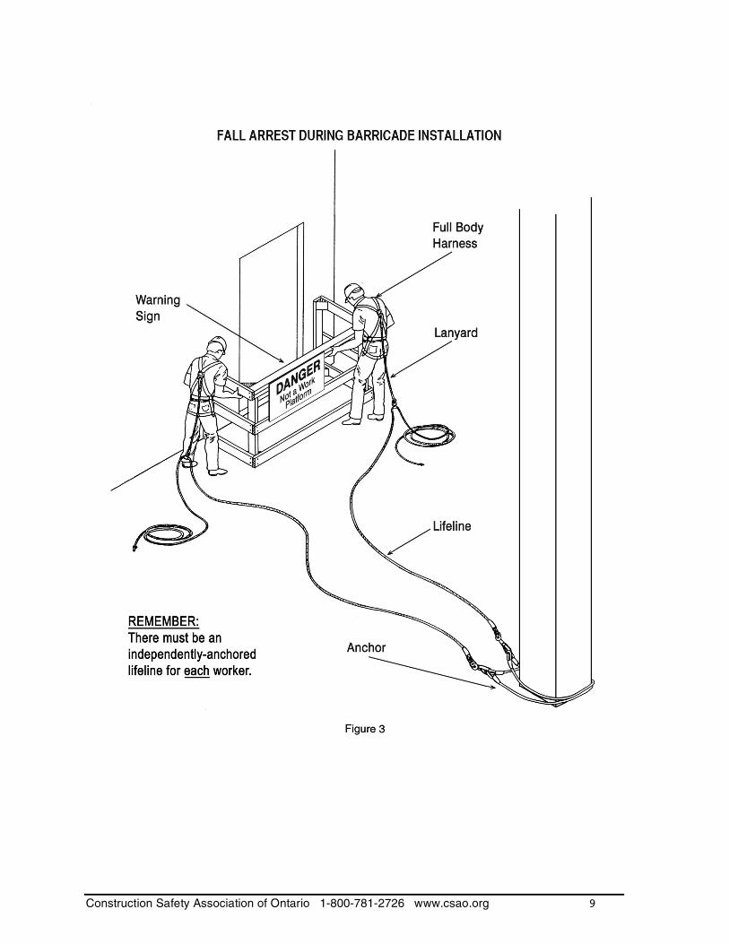
available on the project showing the details. Such anchorage will usually be attached to the crosshead. GENERAL PRECAUTIONS To protect workers or debris from falling into an open hoistway, completely board up or otherwise fully cover hoistway openings. If the hoistway opening is not fully covered, provide overhead protection in the hoistway and guardrails at the opening. The overhead protection should not be more than 3 storeys or 9 metres (30 feet) above a working area (Figures 1 and 2). The overhead protection should be capable of supporting 2.4 kN/m2 (50 pounds per square foot). Planks of 48 mm x 248 mm (2" x 10") No.1 spruce (rough sawn, full size) with a span no greater than 2.1 metres (7 feet) will provide sufficient overhead protection. Beams supporting the planks should be secured in place and have a bearing surface of at least 200 mm (8 inches) at the ends. Do not use the overhead protection as a working platform. Post signs indicating that planking for overhead protection is not to be used as a working platform (Figures 1, 2 and 3). A fall-arrest system attached to a suitable anchor must be worn by workers while installing or removing guardrails and overhead protection, and while boarding up or tearing down elevator doorways (Figure 3).
Construction Safety Association of Ontario 1-800-781-2726 www.csao.org 7
Construction Safety Association of Ontario 1-800-781-2726 www.csao.org 8
Construction Safety Association of Ontario 1-800-781-2726 www.csao.org 9
Construction Safety Association of Ontario 1-800-781-2726 www.csao.org 10
FALL PROTECTION DURING RAIL INSTALLATION There are two basic methods of installing brackets and rails: 1) The first method requires scaffolding the
entire height of the hoistway and is usually only used for elevators of moderate height. For situations where travel is in excess of 15 metres (50 feet), a professional engineer must be consulted.
2) The second method requires scaffolding to set up the basic structural car components and the first length of rails, and to hook up the basic running components of the car. Workers then use the car to install the balance of the brackets and rails.
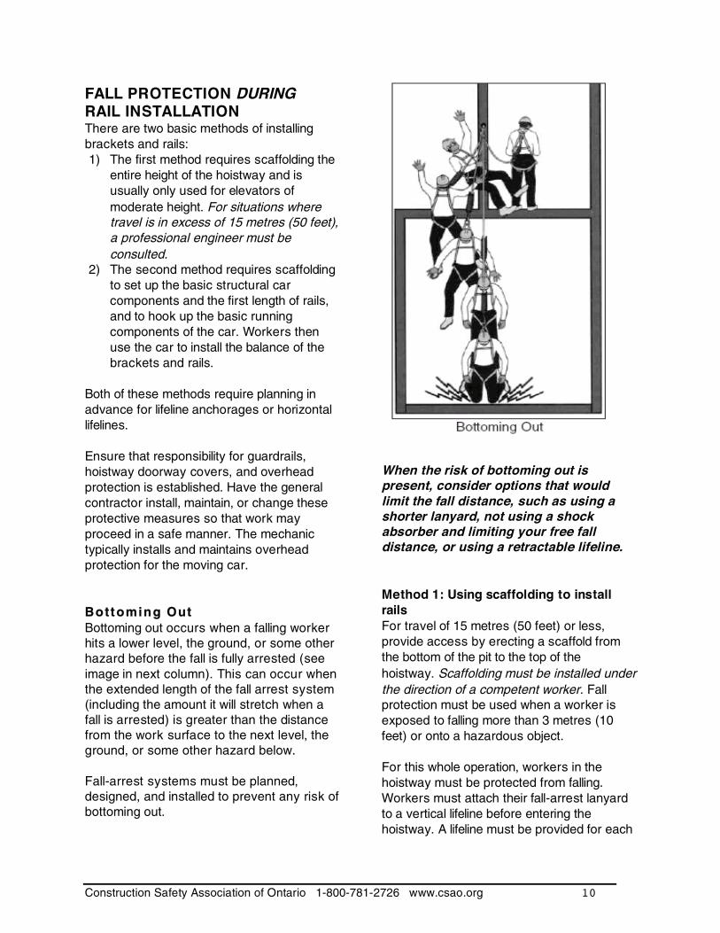
Both of these methods require planning in advance for lifeline anchorages or horizontal lifelines. Ensure that responsibility for guardrails, hoistway doorway covers, and overhead protection is established. Have the general contractor install, maintain, or change these protective measures so that work may proceed in a safe manner. The mechanic typically installs and maintains overhead protection for the moving car. Bottoming Out Bottoming out occurs when a falling worker hits a lower level, the ground, or some other hazard before the fall is fully arrested (see image in next column). This can occur when the extended length of the fall arrest system (including the amount it will stretch when a fall is arrested) is greater than the distance from the work surface to the next level, the ground, or some other hazard below. Fall-arrest systems must be planned, designed, and installed to prevent any risk of bottoming out.
When the risk of bottoming out is present, consider options that would limit the fall distance, such as using a shorter lanyard, not using a shock absorber and limiting your free fall distance, or using a retractable lifeline. Method 1: Using scaffolding to install rails For travel of 15 metres (50 feet) or less, provide access by erecting a scaffold from the bottom of the pit to the top of the hoistway. Scaffolding must be installed under the direction of a competent worker. Fall protection must be used when a worker is exposed to falling more than 3 metres (10 feet) or onto a hazardous object. For this whole operation, workers in the hoistway must be protected from falling. Workers must attach their fall-arrest lanyard to a vertical lifeline before entering the hoistway. A lifeline must be provided for each
Construction Safety Association of Ontario 1-800-781-2726 www.csao.org 11
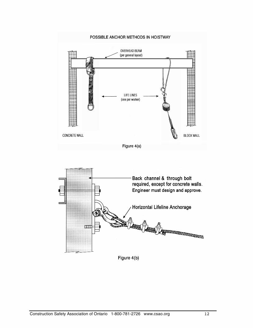
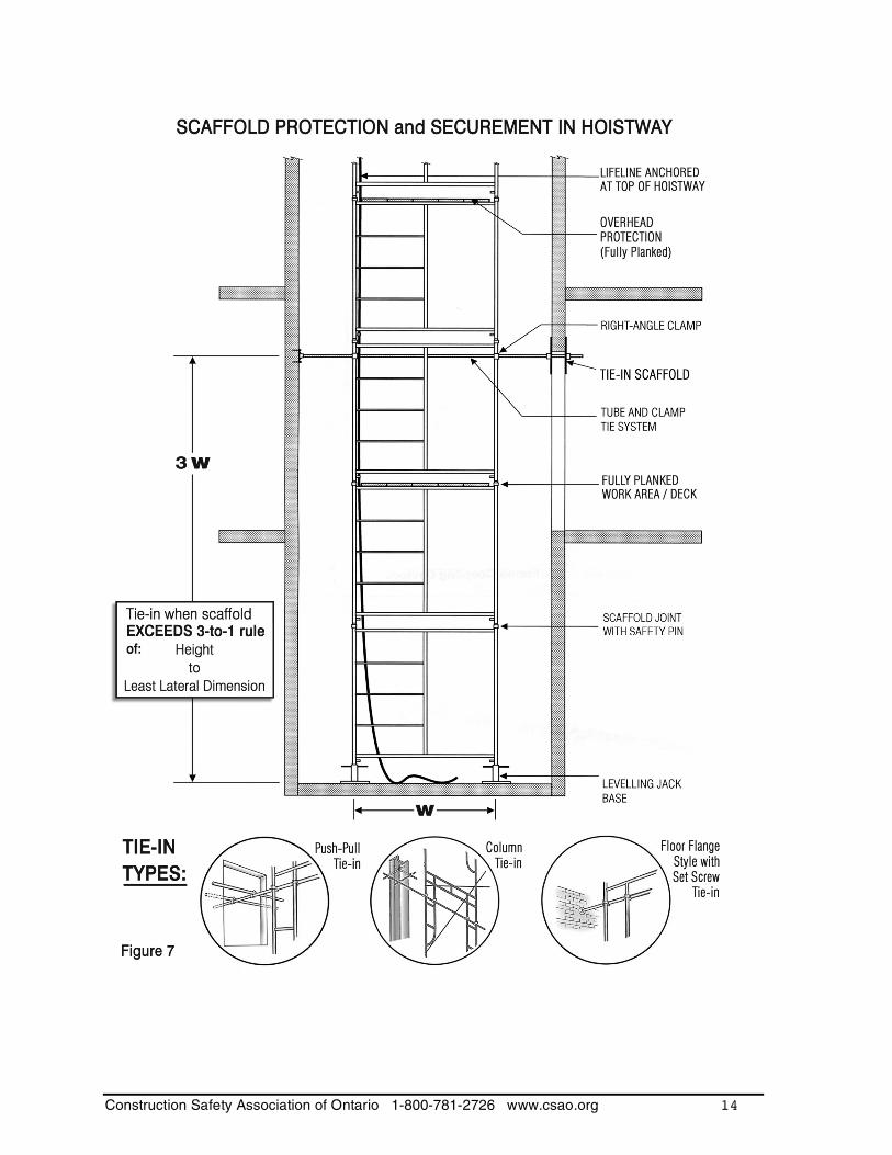
worker and be adequately anchored from above. Thread the lifeline down inside the scaffold frames. Anchorage for the lifeline may be provided by special anchors installed in the hoistway, by structural steel, or by a horizontal line installed across the hoistway and anchored on either side. A beam in use for hoisting must not be used as a lifeline anchor point (Figures 4a and 4b). The anchorage components must be designed by a professional engineer. Use a "gin" wheel or other hoisting device to hoist scaffold components. Use only rated devices with their working load limit (WWL) stamped on them. The gin wheel must be attached to an appropriate hoisting point. Remember, the lifeline must be anchored independently of a hoisting beam. Scaffold platforms must be completely decked-in before the next tier of frames and braces is installed or dismantled. Erect scaffold towers plumb and level by using the adjustable base plates. Base plates and frames should be pinned together to withstand both tension and compression in accordance with manufacturers' instructions. Some methods of pinning scaffolds together are shown in Figure 6. Tie the scaffold to the structure at vertical distances which do not exceed 3 times the least lateral dimension or no more than 3 frames in height for standard 5 x 5 frame systems (Figure 7). Hang worker lifelines inside the confines of the scaffold frames when preparing to install the brackets and rails. The workers can then climb up or down and be protected by the fall-arrest system. When installing brackets or rails, workers must remain hooked up to the fall-arrest system at all times.
Construction Safety Association of Ontario 1-800-781-2726 www.csao.org 12
Construction Safety Association of Ontario 1-800-781-2726 www.csao.org 13
Photo courtesy of Miller Fall Protection, Franklin, PA.
Construction Safety Association of Ontario 1-800-781-2726 www.csao.org 14
Construction Safety Association of Ontario 1-800-781-2726 www.csao.org 15
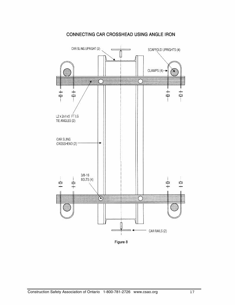
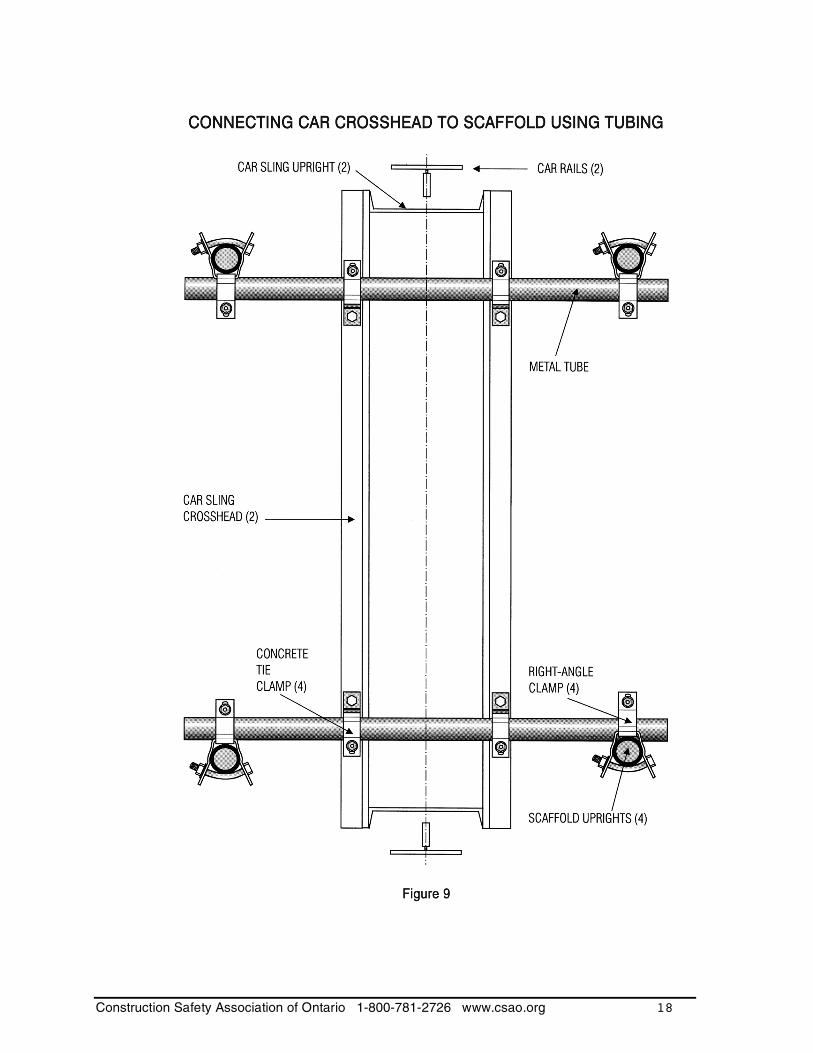
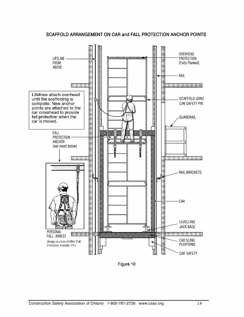
Method 2: Using the car to install rails If the hoistway is many storeys in height, it is common practice to install the rail system using the completed platform of the elevator car. For this method, scaffolds are usually erected to a level of 5 tiers in height or about 7.5 metres (25 feet) using the standard procedures described in “Method 1”, above. Each working level of scaffolding should be decked in with planks or with prefab platforms (Figure 7). Once the first level of rails is installed, the top three or four tiers of scaffold frames are dismantled. Prepare for the installation of the car sling and platform by double-planking the scaffold platform. The next operation is to install the car sling, safety planks, bottom shoes, stiles, and crosshead. Scaffolding two tiers in height above the basic platform will be required to install the stiles and crosshead. When the car sling has been installed and the car platform is in place, the scaffolding is then re-erected to provide access for further work such as installation of cabling and further installation of brackets and rails. Alternate methods may be used such as attaching a platform to the crosshead. Remember: Workers in the hoistway must continue to wear a fall-arrest system attached to vertical lifelines anchored above until the scaffolding is complete. The top of the scaffolding should be completely decked-in for overhead protection. Again, 48 mm x 248 mm (2" x 10") full size No.1 spruce planks spanning no more than 2.1 metres (7' 0") should provide adequate protection (Figure 10). The scaffolding should be fully decked in at each level where work will be performed. The scaffolding should also be fixed to the car. One method is to attach members to the
car's crosshead as illustrated in Figures 8 and 9. The cabling and counterweight system should then be installed. During these operations, workers in the hoistway must continue to be protected from falling by wearing a fall-arrest system attached to a vertical lifeline anchored overhead, as before. The overhead protection in the hoistway can now be removed. The travelling cable, running buttons, and lights should then be hooked up. Install the governor and governor rope in preparation for checking out the running operation of the car. Install buffers before proceeding to run the car and install additional brackets and rails. At this time, the lifelines attached overhead are supplemented by additional lifelines that will be used to provide fall protection when the car is moved. These new anchor points attach to the car crosshead (Figure 10). Additional rope lifelines or a retractable lifeline may be suitable. These lifelines should be dropped down inside the scaffolding to provide fall protection while installers move up and down from one working level to another (Figure 10). This arrangement should remain in place until the work of installing brackets and rails has been completed, at which point the scaffolding on the car can be dismantled. FALL PROTECTION AFTER RAIL INSTALLATION Work from the car platform After rails and brackets are installed and the scaffolding has been dismantled, you can prepare the car platform for the rest of the work. Before it can be used as an access

Construction Safety Association of Ontario 1-800-781-2726 www.csao.org 16
platform, you need to install a guardrail and provisions for a fall-arrest system. Guardrails Guardrails must conform to Section 26.3 of the Construction Regulation (Ontario Regulation 213/91). A standard guardrail consists of a top rail, mid-rail, and toeboard. Guardrails must be able to withstand the loads specified in Section 26.3(5). Fall protection is provided by the use of standard guardrails on two sides and the rear of the car platform with no front rail. Guardrails should be located as close as possible to the car perimeter on the two sides and rear of the car platform. On the front side where the elevator doors are located, the gap between the wall and the end of the guardrail should be no greater than 300 mm (12”). Where a front guardrail (facing door openings) is used, it will consist of a single rail of equal size to the other top rails. It should be placed at a height of 0.9 to 1.1 metres (3’ to 3’ 7”). It should also be located at least 300 mm (12”) from the front of the platform. Since a considerable portion of the work carried out from the car platform at this stage of construction will be at the front of the car, this front rail should be removable. When the car is moved, workers are to be tied off with a fall-arrest system as described in “Method 2”. Lifelines that provide fall protection while the car is moved attach to the car crosshead. Workers must also be tied off when the car platform is stationary if openings in the guardrail or between the ends of the guardrail and a wall are greater than 300 mm (12”). Unless the gap between the guardrail and the front wall is greater than 300 mm (12”), workers do not have to tie off during car platform movement once the hoistway walls and doors are installed.
Construction Safety Association of Ontario 1-800-781-2726 www.csao.org 17
Construction Safety Association of Ontario 1-800-781-2726 www.csao.org 18
Construction Safety Association of Ontario 1-800-781-2726 www.csao.org 19
Construction Safety Association of Ontario 1-800-781-2726 www.csao.org 20
HOISTING WITH A CAPSTAN
Construction Safety Association of Ontario 1-800-781-2726 www.csao.org 21
HOISTING WITH A CAPSTAN
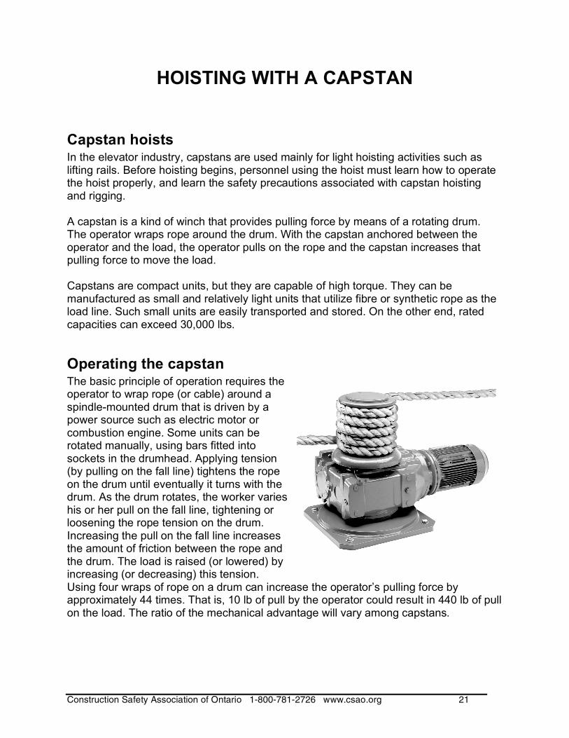
Capstan hoists In the elevator industry, capstans are used mainly for light hoisting activities such as lifting rails. Before hoisting begins, personnel using the hoist must learn how to operate the hoist properly, and learn the safety precautions associated with capstan hoisting and rigging. A capstan is a kind of winch that provides pulling force by means of a rotating drum. The operator wraps rope around the drum. With the capstan anchored between the operator and the load, the operator pulls on the rope and the capstan increases that pulling force to move the load. Capstans are compact units, but they are capable of high torque. They can be manufactured as small and relatively light units that utilize fibre or synthetic rope as the load line. Such small units are easily transported and stored. On the other end, rated capacities can exceed 30,000 lbs.
Operating the capstan The basic principle of operation requires the operator to wrap rope (or cable) around a spindle-mounted drum that is driven by a power source such as electric motor or combustion engine. Some units can be rotated manually, using bars fitted into sockets in the drumhead. Applying tension (by pulling on the fall line) tightens the rope on the drum until eventually it turns with the drum. As the drum rotates, the worker varies his or her pull on the fall line, tightening or loosening the rope tension on the drum. Increasing the pull on the fall line increases the amount of friction between the rope and the drum. The load is raised (or lowered) by increasing (or decreasing) this tension. Using four wraps of rope on a drum can increase the operator’s pulling force by approximately 44 times. That is, 10 lb of pull by the operator could result in 440 lb of pull on the load. The ratio of the mechanical advantage will vary among capstans.
Construction Safety Association of Ontario 1-800-781-2726 www.csao.org 22
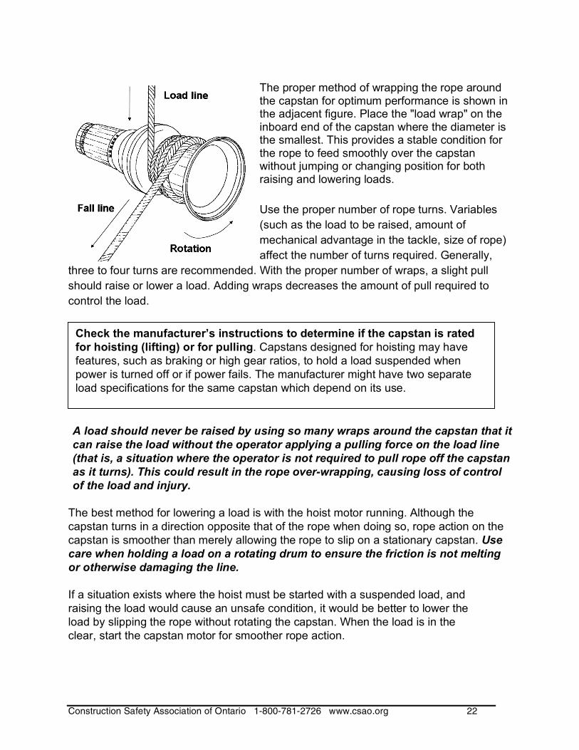
The proper method of wrapping the rope around the capstan for optimum performance is shown in the adjacent figure. Place the "load wrap" on the inboard end of the capstan where the diameter is the smallest. This provides a stable condition for the rope to feed smoothly over the capstan without jumping or changing position for both raising and lowering loads.
Use the proper number of rope turns. Variables
(such as the load to be raised, amount of
mechanical advantage in the tackle, size of rope)
affect the number of turns required. Generally,
three to four turns are recommended. With the proper number of wraps, a slight pull
should raise or lower a load. Adding wraps decreases the amount of pull required to
control the load.
A load should never be raised by using so many wraps around the capstan that it
can raise the load without the operator applying a pulling force on the load line
(that is, a situation where the operator is not required to pull rope off the capstan
as it turns). This could result in the rope over-wrapping, causing loss of control
of the load and injury.
The best method for lowering a load is with the hoist motor running. Although the
capstan turns in a direction opposite that of the rope when doing so, rope action on the
capstan is smoother than merely allowing the rope to slip on a stationary capstan. Use
care when holding a load on a rotating drum to ensure the friction is not melting
or otherwise damaging the line.
If a situation exists where the hoist must be started with a suspended load, and
raising the load would cause an unsafe condition, it would be better to lower the
load by slipping the rope without rotating the capstan. When the load is in the
clear, start the capstan motor for smoother rope action.
Check the manufacturer’s instructions to determine if the capstan is rated
for hoisting (lifting) or for pulling. Capstans designed for hoisting may have
features, such as braking or high gear ratios, to hold a load suspended when
power is turned off or if power fails. The manufacturer might have two separate
load specifications for the same capstan which depend on its use.
Construction Safety Association of Ontario 1-800-781-2726 www.csao.org 23
Always use at least as many wraps of rope on the drum to lower a load as is required to
lift that load.
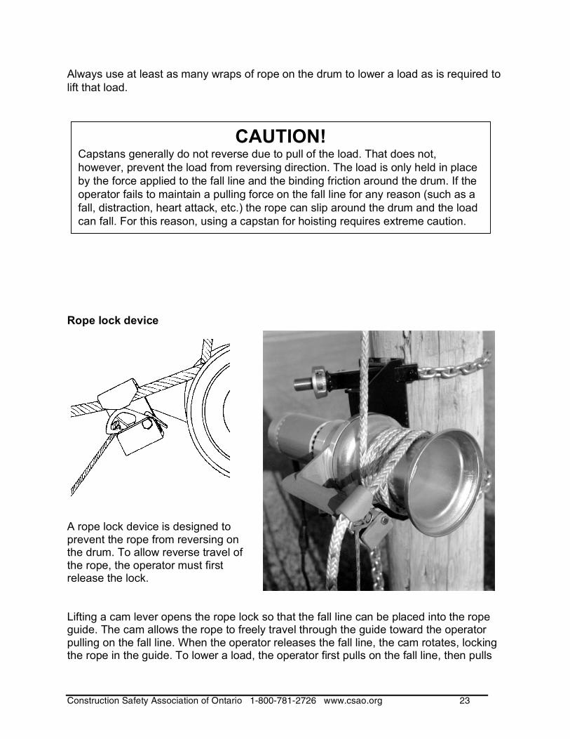
Rope lock device
A rope lock device is designed to prevent the rope from reversing on the drum. To allow reverse travel of the rope, the operator must first release the lock. Lifting a cam lever opens the rope lock so that the fall line can be placed into the rope guide. The cam allows the rope to freely travel through the guide toward the operator pulling on the fall line. When the operator releases the fall line, the cam rotates, locking the rope in the guide. To lower a load, the operator first pulls on the fall line, then pulls
CAUTION! Capstans generally do not reverse due to pull of the load. That does not,
however, prevent the load from reversing direction. The load is only held in place
by the force applied to the fall line and the binding friction around the drum. If the
operator fails to maintain a pulling force on the fall line for any reason (such as a
fall, distraction, heart attack, etc.) the rope can slip around the drum and the load
can fall. For this reason, using a capstan for hoisting requires extreme caution.
Construction Safety Association of Ontario 1-800-781-2726 www.csao.org 24
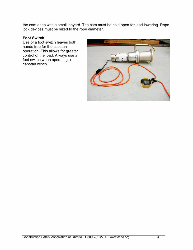
the cam open with a small lanyard. The cam must be held open for load lowering. Rope lock devices must be sized to the rope diameter. Foot Switch Use of a foot switch leaves both hands free for the capstan operation. This allows for greater control of the load. Always use a foot switch when operating a capstan winch.
Construction Safety Association of Ontario 1-800-781-2726 www.csao.org 25
Rigging for capstan hoisting
Calculating a Simple Load
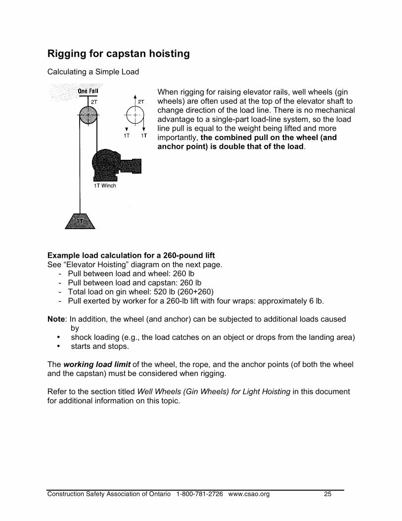
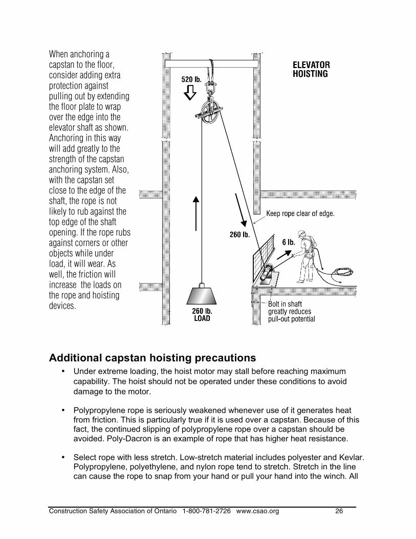
When rigging for raising elevator rails, well wheels (gin wheels) are often used at the top of the elevator shaft to change direction of the load line. There is no mechanical advantage to a single-part load-line system, so the load line pull is equal to the weight being lifted and more importantly, the combined pull on the wheel (and anchor point) is double that of the load.
Example load calculation for a 260-pound lift See “Elevator Hoisting” diagram on the next page.
- Pull between load and wheel: 260 lb - Pull between load and capstan: 260 lb - Total load on gin wheel: 520 lb (260+260) - Pull exerted by worker for a 260-lb lift with four wraps: approximately 6 lb.
Note: In addition, the wheel (and anchor) can be subjected to additional loads caused
by • shock loading (e.g., the load catches on an object or drops from the landing area) • starts and stops.
The working load limit of the wheel, the rope, and the anchor points (of both the wheel and the capstan) must be considered when rigging. Refer to the section titled Well Wheels (Gin Wheels) for Light Hoisting in this document for additional information on this topic.
Construction Safety Association of Ontario 1-800-781-2726 www.csao.org 26
When anchoring a capstan to the floor, consider adding extra protection against pulling out by extending the floor plate to wrap over the edge into the elevator shaft as shown. Anchoring in this way will add greatly to the strength of the capstan anchoring system. Also, with the capstan set close to the edge of the shaft, the rope is not likely to rub against the top edge of the shaft opening. If the rope rubs against corners or other objects while under load, it will wear. As well, the friction will increase the loads on the rope and hoisting devices.
Additional capstan hoisting precautions • Under extreme loading, the hoist motor may stall before reaching maximum
capability. The hoist should not be operated under these conditions to avoid
damage to the motor.
• Polypropylene rope is seriously weakened whenever use of it generates heat from friction. This is particularly true if it is used over a capstan. Because of this fact, the continued slipping of polypropylene rope over a capstan should be avoided. Poly-Dacron is an example of rope that has higher heat resistance.
• Select rope with less stretch. Low-stretch material includes polyester and Kevlar.
Polypropylene, polyethylene, and nylon rope tend to stretch. Stretch in the line can cause the rope to snap from your hand or pull your hand into the winch. All
Construction Safety Association of Ontario 1-800-781-2726 www.csao.org 27
rope will stretch. Be cautious when using long lengths of rope. Release the line tension slowly to avoid the line recoiling and whipping.
• Overhead loads can fall. Do not allow people to stand under or near the load.
The operator must keep the rope securely on the capstan drum, and under control.
• Read the operating instructions for the capstan.
DO NOT
use a capstan unless you are competent to do so
lift more than the rated load for any hoisting system components
use any hoisting system components if damaged or malfunctioning
lift people
lift loads above people
stand between load and hoist
let the fall line tangle with operator or equipment
hold loads suspended in the air
remove wraps of rope from the drum while supporting a load.
• Inspect the winch, rope, and other rigging equipment before use. Check for wear,
misuse, damage, or improper functioning. If any of these conditions exist, do not
use the capstan. Tag it and return it to the manufacturer for repairs or replace as
appropriate.

Construction Safety Association of Ontario 1-800-781-2726 www.csao.org 28
TUGGERS (POWERED WINCHES)
Construction Safety Association of Ontario 1-800-781-2726 www.csao.org 29
Tuggers (powered winches)
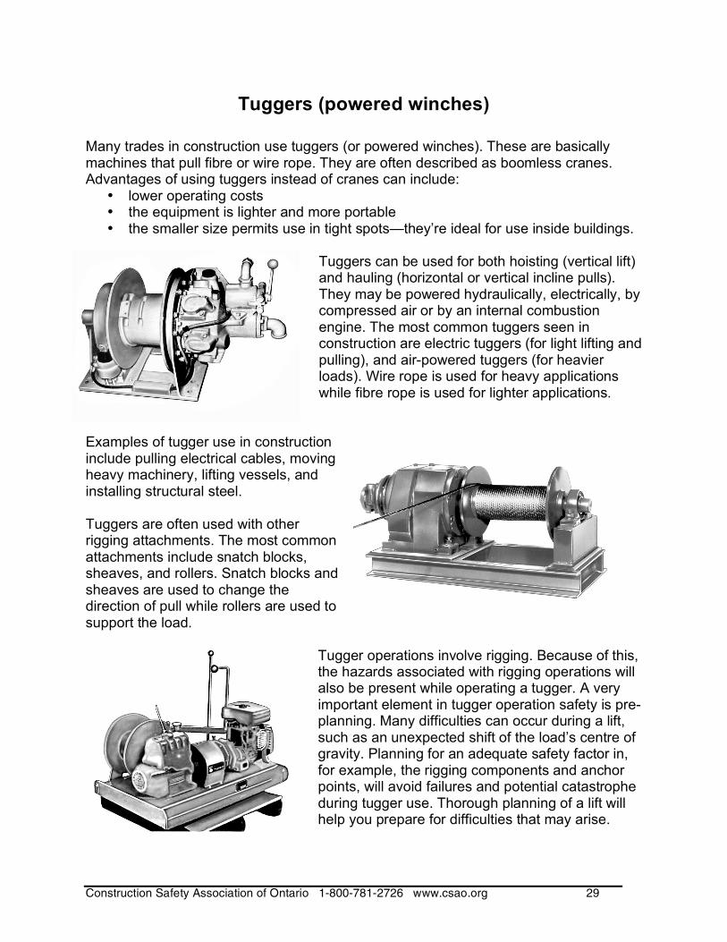
Many trades in construction use tuggers (or powered winches). These are basically machines that pull fibre or wire rope. They are often described as boomless cranes. Advantages of using tuggers instead of cranes can include:
• lower operating costs • the equipment is lighter and more portable • the smaller size permits use in tight spots—they’re ideal for use inside buildings.
Tuggers can be used for both hoisting (vertical lift) and hauling (horizontal or vertical incline pulls). They may be powered hydraulically, electrically, by compressed air or by an internal combustion engine. The most common tuggers seen in construction are electric tuggers (for light lifting and pulling), and air-powered tuggers (for heavier loads). Wire rope is used for heavy applications while fibre rope is used for lighter applications.
Examples of tugger use in construction include pulling electrical cables, moving heavy machinery, lifting vessels, and installing structural steel. Tuggers are often used with other rigging attachments. The most common attachments include snatch blocks, sheaves, and rollers. Snatch blocks and sheaves are used to change the direction of pull while rollers are used to support the load.
Tugger operations involve rigging. Because of this, the hazards associated with rigging operations will also be present while operating a tugger. A very important element in tugger operation safety is pre-planning. Many difficulties can occur during a lift, such as an unexpected shift of the load’s centre of gravity. Planning for an adequate safety factor in, for example, the rigging components and anchor points, will avoid failures and potential catastrophe during tugger use. Thorough planning of a lift will help you prepare for difficulties that may arise.
Construction Safety Association of Ontario 1-800-781-2726 www.csao.org 30
Hazards associated with tugger operation
The kinds of hazards a worker is likely to be exposed to during tugging operations are similar to those in rigging applications. Check for the following hazards, as well as conditions that can create hazards:
Poor communication Lack of training Overloading Failure of tugger and rigging
assembly Fall hazards Failure of anchorage points of the
tugger or rigging components Shifting or other movement of the
tugger or point of anchorage when under load
Brake failure when under load Unexpected movement of the
equipment which can strike or crush a worker handling the load
The moving drum and sheaves which can pinch or crush a worker’s hand
Loose clothing or jewellery caught in drum or sheaves
Electrical hazards when using electrically powered tuggers
Carbon monoxide from combustion by-products in confined spaces
Fire or explosion (if operated in an area of combustible products)
Exposure to hydraulic fluid from hoses breaking or leaks
Improper purging of hydraulic lines Rope coming off the drum Area not isolated from other
workers or public during hoisting or hauling.
A tugger must generate enough pull through the load line to lift, move, or hold the load and any associated rigging. In addition to this pull, there is also stored “potential” energy in the system. A failure in the rigging system can result in a violent whipping of the lift line due to release of this stored energy, and the release of the load. It's of paramount importance to ensure that all rigging and all points of anchorage are able to safely handle all loads, or all potential loads, to which they might be subjected.
For detailed information on powered winches, see CSAO’s data sheet Specialized Rigging: Guidelines for Construction—Hydraulic Gantry Systems, Overhead Cranes, Jacks and Rollers, Tuggers (DS035).
All rigging components and points of anchorage may be subjected to forces greater than the weight of the load.
Construction Safety Association of Ontario 1-800-781-2726 www.csao.org 31
WELL WHEELS (GIN WHEELS) for
LIGHT HOISTING
Construction Safety Association of Ontario 1-800-781-2726 www.csao.org 32
WELL WHEELS (GIN WHEELS) FOR LIGHT HOISTING
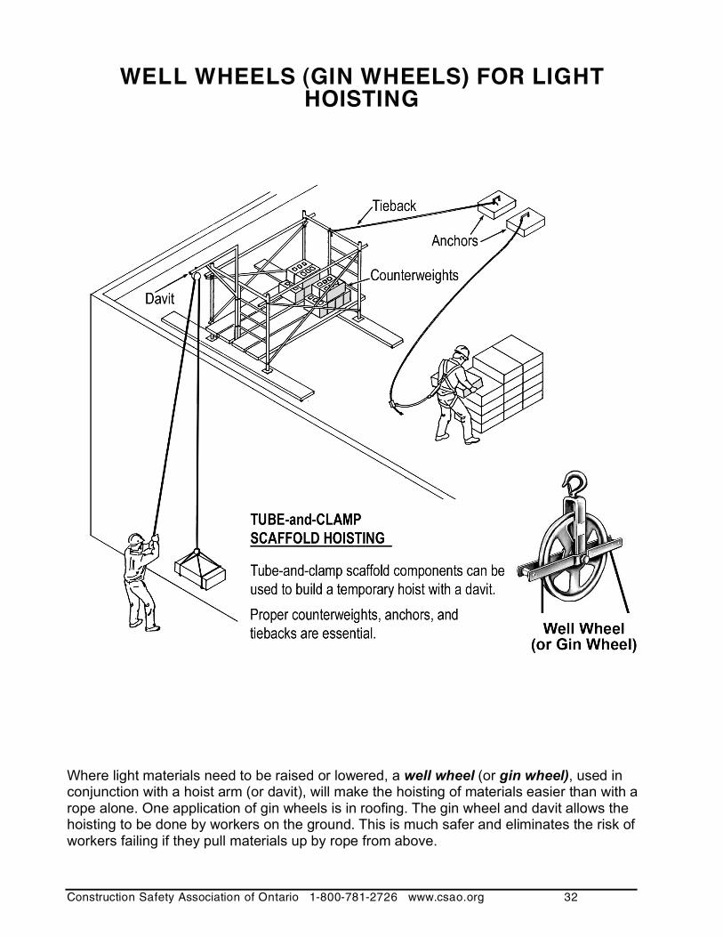
Where light materials need to be raised or lowered, a well wheel (or gin wheel), used in conjunction with a hoist arm (or davit), will make the hoisting of materials easier than with a rope alone. One application of gin wheels is in roofing. The gin wheel and davit allows the hoisting to be done by workers on the ground. This is much safer and eliminates the risk of workers failing if they pull materials up by rope from above.
Construction Safety Association of Ontario 1-800-781-2726 www.csao.org 33
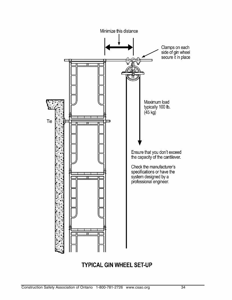
Loads lifted by a gin wheel are limited by the capacity of the structure supporting the wheel, the individual components used, and the anchor point. Check the manufacturer’s recommendations when determining the maximum load that can be safely raised. Lifts should normally be no more than 100 lb (45 kg) unless engineered structural provisions are made. Although the gin wheel itself may have a capacity far in excess of 100 lb, the maximum load is dependent on the weakest link in the entire system. The Construction Regulation (Ontario Regulation 213/91) requires the load rating and weight to be legibly stamped or cast on the “hook block.” In this type of system, the weakest links are usually the structure supporting the wheel, the capacity and condition of the rope used to lift the load, and the worker. The weight and strength of the person pulling on the rope limits the weight that can be hoisted with a safe measure of control of the lift. The physical limitations of the operator can be overcome by using a hand-operated or machine-operated winch. Using a winch requires careful planning. Mechanical devices can generate a great amount of force quickly. Evaluate the rigging components to ensure that you won’t exceed their limitations.
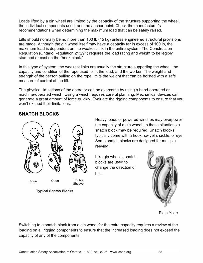
SNATCH BLOCKS Heavy loads or powered winches may overpower
the capacity of a gin wheel. In these situations a
snatch block may be required. Snatch blocks
typically come with a hook, swivel shackle, or eye.
Some snatch blocks are designed for multiple
reeving.
Like gin wheels, snatch
blocks are used to
change the direction of
pull.
Switching to a snatch block from a gin wheel for the extra capacity requires a review of the
loading on all rigging components to ensure that the increased loading does not exceed the
capacity of any of the components.
Plain Yoke
Construction Safety Association of Ontario 1-800-781-2726 www.csao.org 34
Construction Safety Association of Ontario 1-800-781-2726 www.csao.org 35
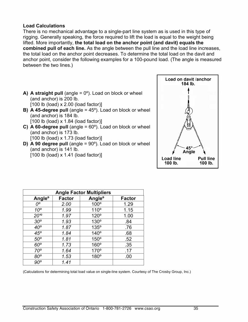
Load Calculations There is no mechanical advantage to a single-part line system as is used in this type of rigging. Generally speaking, the force required to lift the load is equal to the weight being lifted. More importantly, the total load on the anchor point (and davit) equals the combined pull of each line. As the angle between the pull line and the load line increases, the total load on the anchor point decreases. To determine the total load on the davit and anchor point, consider the following examples for a 100-pound load. (The angle is measured between the two lines.) A) A straight pull (angle = 0º). Load on block or wheel
(and anchor) is 200 lb. [100 lb (load) x 2.00 (load factor)]
B) A 45-degree pull (angle = 45º). Load on block or wheel (and anchor) is 184 lb. [100 lb (load) x 1.84 (load factor)]
C) A 60-degree pull (angle = 60º). Load on block or wheel (and anchor) is 173 lb. [100 lb (load) x 1.73 (load factor)]
D) A 90 degree pull (angle = 90º). Load on block or wheel (and anchor) is 141 lb. [100 lb (load) x 1.41 (load factor)]
Angle Factor Multipliers
Angleº Factor Angleº Factor
0º 2.00 100º 1.29
10º 1.99 110º 1.15
20'º 1.97 120º 1.00
30º 1.93 130º .84
40º 1.87 135º .76
45º 1.84 140º .68
50º 1.81 150º .52
60º 1.73 160º .35
70º 1.64 170º .17
80º 1.53 180º .00
90º 1.41 (Calculations for determining total load value on single-line system. Courtesy of The Crosby Group, Inc.)
Construction Safety Association of Ontario 1-800-781-2726 www.csao.org 36
Working Load Limit (WLL) Always consider the safety factor of each component when calculating loads. The safety factor provides additional protection from dangers such as accidental overloading and wear and tear on components. It is used in calculating the Working Load Limit (WLL) of a component. The WLL is the maximum load to be applied to a component. To incorporate the safety factor in calculating the WLL of a gin wheel, consider the following example:
For a gin wheel rated at 1000 lb, having a manufacturer's designed safety factor of 3,
what is its WLL?
Section 172 (1)(d) of the Construction Regulation requires a safety
factor of 5. This requirement is greater than the designed safety factor. The gin wheel capacity must be reduced accordingly.
The WLL of the gin wheel is calculated as follows: 1000 lb x (3 / 5) = 600lb.
In this example, even though the gin wheel has a stamped capacity of 1000 lb, it can be used
to lift only a maximum of 600 lb safely.
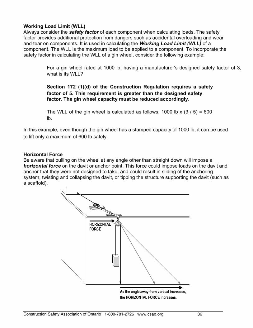
Horizontal Force Be aware that pulling on the wheel at any angle other than straight down will impose a horizontal force on the davit or anchor point. This force could impose loads on the davit and anchor that they were not designed to take, and could result in sliding of the anchoring system, twisting and collapsing the davit, or tipping the structure supporting the davit (such as a scaffold).
Construction Safety Association of Ontario 1-800-781-2726 www.csao.org 37
Additional safety measures • Keep the landing areas clear, both above and below. • Ensure workers are using appropriate fall protection where required. • Keep hands, body, and clothing away from moving parts to avoid pinch points. • Wear gloves to protect hands from rope burn. Other personal protective equipment such
as eyewear and a hard hat should be used to protect you from falling dirt or material. • Take into account the potential for shock loading. Shock loading results from rapid
movement or jerking of the load and can significantly add to the total load. Examples of what can contribute to this type of loading include sudden pulls on the line during lifting and lowering, and sliding the load over the edge of a roof (without first having taken up the full weight of the load).
• Ensure all loads are secured to prevent shifting of the load. • Inspect the equipment and line before use and after any shocks are placed on the system.
If you find any problems, take the system out of service until repairs have been made by a person competent to do so. At the very least, check for the following:
The anchor mechanism for the gin wheel and/or davit is secure. Proper attachment of the gin wheel: make sure the hook latch is in place and
closed. Deformation of support components (including the gin wheel). Integrity of the line. Loose nuts, bolts, pins, or other locking devices.
Construction Safety Association of Ontario 21 Voyager Court South
Etobicoke, Ontario M9W 5M7 Canada 1-800-781-2726 fax (416) 674-8866 www.csao.org
W020