Elevator actuator housing bay flight mission thermal ...
11
HAL Id: hal-01396639 https://hal.archives-ouvertes.fr/hal-01396639 Submitted on 14 Nov 2016 HAL is a multi-disciplinary open access archive for the deposit and dissemination of sci- entific research documents, whether they are pub- lished or not. The documents may come from teaching and research institutions in France or abroad, or from public or private research centers. L’archive ouverte pluridisciplinaire HAL, est destinée au dépôt et à la diffusion de documents scientifiques de niveau recherche, publiés ou non, émanant des établissements d’enseignement et de recherche français ou étrangers, des laboratoires publics ou privés. Elevator actuator housing bay flight mission thermal integrated analysis Grégoire Lenoble, Marie Olivier, David Donjat, Anton Steblinkin, Jimenez Olazabal To cite this version: Grégoire Lenoble, Marie Olivier, David Donjat, Anton Steblinkin, Jimenez Olazabal. Elevator actua- tor housing bay flight mission thermal integrated analysis. Recent Advances in Aerospace Actuation Systems and Components, Mar 2016, TOULOUSE, France. hal-01396639
Transcript of Elevator actuator housing bay flight mission thermal ...

HAL Id: hal-01396639https://hal.archives-ouvertes.fr/hal-01396639
Submitted on 14 Nov 2016
HAL is a multi-disciplinary open accessarchive for the deposit and dissemination of sci-entific research documents, whether they are pub-lished or not. The documents may come fromteaching and research institutions in France orabroad, or from public or private research centers.
L’archive ouverte pluridisciplinaire HAL, estdestinée au dépôt et à la diffusion de documentsscientifiques de niveau recherche, publiés ou non,émanant des établissements d’enseignement et derecherche français ou étrangers, des laboratoirespublics ou privés.
Elevator actuator housing bay flight mission thermalintegrated analysis
Grégoire Lenoble, Marie Olivier, David Donjat, Anton Steblinkin, JimenezOlazabal
To cite this version:Grégoire Lenoble, Marie Olivier, David Donjat, Anton Steblinkin, Jimenez Olazabal. Elevator actua-tor housing bay flight mission thermal integrated analysis. Recent Advances in Aerospace ActuationSystems and Components, Mar 2016, TOULOUSE, France. �hal-01396639�

Recent Advances in Aerospace Actuation Systems and Components, March 16-17, 2016, Toulouse, France
Elevator actuator housing bay flight mission thermal integrated analysis
LENOBLE Grégoire OLIVIER, Marie
Siemens PLM Software, LMS Engineering La Cité Internationale
84 Quai Charles de Gaulle 69006 Lyon France
Phone: +33 (0)4 37 91 61 54 Email: [email protected]
DONJAT David
ONERA Centre de Toulouse 2, Avenue Edouard Belin 31055 Toulouse France
Phone: +33 (0)5 62 25 28 08 Email: [email protected]
STEBLINKIN Anton TsAGI (Central Aerohydrodynamic Institute
named after prof. N.E. Zhukovsky) Zhukovsky st. 1, Zhukovsky
Moscow region, 140180 Russia Phone: +7 (495) 556-38-38
Email: [email protected]
JIMENEZ OLAZABAL Andrés CESA
P.° John Lennon, n°4 28906 Getafe – Madrid, Spain
Phone: +34 91 624 02 28 Email: [email protected]
ABSTRACT Aircraft hydraulic systems traditionally provide power for flight surface actuation, but are heavy, complex to maintain in service, and consume significant amounts of energy. Electrical based actuators help tackle these issues, but come with other challenges, such as thermal integration. Indeed, the close vicinity of several heat sources (hydraulic pump and bloc, electrical motor, control unit) in a cavity that is only passively cooled makes it difficult to guarantee the electrical motor and Electronic Control Unit (ECU) safe operation over the entire aircraft mission from a thermal point of view. In addition, systems thermal behavior can be critical when used inside composite structures that can lose durability under high temperatures.
Collaborative European-Russian project RESEARCH (w3.onera.fr/RESEARCH/) has enabled the thermal analysis of a regional aircraft stabilizer bay that houses two elevator actuators, so as to support and optimize actuator motor design. This analysis largely relied on Model Based Systems Engineering (MBSE) given the early actuator design phase and the need for mission-wide analysis, through a number of varying scenarios. However the additional insight of three-dimensional analysis has also been included with simulations performed at thermally critical flight conditions. The methodology, models, outputs and implications for motor design gained from this study are described in this paper.
KEYWORDS Elevator; actuator; EHA, EMA; MBSE; LMS Amesim; CFD; Fluent; flight mission; thermal integration.
INTRODUCTION
Context, Need for thermal analysis The reduction of fuel burn has become a priority for most aircraft operators due to environmental and cost implications. Such interest has encouraged the aerospace industry to look at ways of minimizing fuel consumption, concluding that the approach towards a More Electrical Aircraft (MEA), i.e. an aircraft that uses electricity to operate its consumers, could provide some benefits. This approach tends to remove hydraulic actuators and the hydraulic systems that feed them, as they require a significant amount of maintenance, are heavier and consume significant amounts of energy. Additionally, electrical components allow for a higher integration of sensors that monitor actuators performance and structural integrity (from a safety point of view); and help implement a higher level of “intelligence”, improving the actuation system integration within the aircraft controlling system as a result.
Despite the potential benefits indicated above, such as weight reduction, increased safety and reliability, lower consumption, reduced maintenance costs, etc.… electrical actuators are not fully embraced by the industry due the limitations they present in their current development stage, which prevent them from being used massively or in critical areas, such as aircraft primary flight control surfaces. These limitations are: high actuator weight, safety concerns due to the jamming probability of Electro-Mechanical Actuators (EMAs), and Electro Magnetic Compatibility (EMC) issues. Systems thermal behavior and integration is also another very challenging issue.

Recent Advances in Aerospace Actuation Systems and Components, March 16-17, 2016, Toulouse, France
Indeed, it is well known that the reliability of EMAs and Electro-Hydrostatic Actuators (EHAs) for flight controls depends on their operating temperature. The A380 flight control EHA is a great example [Bossche], being used as a backup actuator. Thus, EHAs and EMAs that are constantly working in an active regime need to see their thermal management improved: removing the traditional hydraulic network imposes the need to dissipate heat generated by the actuation system (motor, ECU, and harness) differently. The management of this thermal environment needs both new cooling technologies (see [Lawson]) and design optimization methods. The latter is a key enabler for designers to address thermal integration earlier in the design process.
For the above reasons, and the fact that the RESEARCH program is a wide objective oriented cooperative project, the decisions was taken to analyze the thermal integration of the actuation system under development by the consortium partners.
Cavity configuration Based on the results of weight and safety analyses of the different possible FCAS architectures performed by the RESEARCH consortium in the first project phase, the elevator control system of a regional passenger aircraft (100-seater) was chosen as the target application to be developed. The control system should consist of an EMA (under CESA’s development, Spain) and EHA (under Moscow Aviation Institute (MAI) development, Russia) operating in parallel (active/active configuration).
The preliminary actuators characteristics for such configuration were the following:
Stroke ±30mm Maximum rod velocity 55 mm/s
Maximum rod velocity under 25 mm/s
Stall load 20 kN
EMA and EHA designs identified as candidates for this analysis are shown with Figure 1, Figure 2 and the ECU envisaged for their control is shown with Figure 3.
Figure 1. EMA isometric view (CESA)
Figure 2. EHA side and top views with dimensions (MAI)
Figure 3. ECU isometric view (Tecnalia)
The weight information available for the above mentioned hardware is summarized with Table 1.
Hardware Weight (kg) EHA Motor 15 EHA Body 4 EHA Pump 3
EHA Reverse Valve 0,5 EHA Piston 3
EMA Body (items 1,3,6) 4,2 EMA Shaft (item 2) 5,1 EMA Motor (item 4) 10,7
ECU 2,5
Table 1 : Hardware weight summary (partners)
The actuator housing cavity is shown with Figure 4.
Figure 4. Stabilizer cavity with actuating devices:
EHA/EHA/ECU (ONERA)

Recent Advances in Aerospace Actuation Systems and Components, March 16-17, 2016, Toulouse, France
The flight mission The flight scenario is based on a real flight record that contains the data arrays of Indicated Air Speed (IAS) and aircraft altitude (both shown with Figure 5), as well as external forces under hinge moments and other flight parameters. This flight record thus fully determines the actuation system heat losses and heat dissipation processes.
Figure 5. Aircraft IAS and altitude from the flight-record
Thermal analysis
MBSE cavity model The methodology of the actuation system thermal behavior analysis described implies the wide use of simulation, which as a first step was represented by the simulation of the cavity system thermal behavior in the LMS Imagine.Lab Amesim software, over the flight mission described above.
1) Cavity boundary conditions
The elevator actuator operates inside a given thermal context, which will interact with the actuator bay, and even influence its thermal behavior. The following interfaces to the actuator are considered: outside air, Sun radiation, cavity structure.
Outside airflow provides a large cooling effect to the cavity outside shell. This is captured both on the top and bottom panels (see Figure 6 and Figure 7), assuming airflow over a horizontal flat plate configuration. Depending on the flight regime and air properties, forced and free convections are calculated with laminar or turbulent equations [Incropera].
In order to ensure a smooth mathematical model over the entire range of convection regimes (purely free, mixed, purely forced), a unique Nusselt number combines the free and forced ones, so that a unique convection Heat Transfer Coefficient (HTC) can be calculated as per (1). In this outside convection case, the characteristic dimension L is the total stabilizer outside area (top and bottom) divided by its perimeter.
∗ / (1)
Note that the air viscosity, thermal conductivity, specific heat, density and speed are dynamically updated during the aircraft mission simulation.
Figure 6. Cavity top panel
As shown with Figure 6, Sun radiation onto the stabilizer cavity is accounted for with (2), where θ is the angle between the cavity surface (normal vector) and the Sun direction (set to 0° so as to consider maximum Sun radiation), and abscoeff stands for the surface absorption factor.
∗ cos ∗ ∗ 2
This Sun radiation is complemented with the radiative exchange the surface has with outside ambient air, as per (7), and using εgw as the outside air and cavity panel emission factor.
⋅ ⋅ ⋅ (3)
Note that equation (3) is a particular case of the general radiation equation that assumes an infinite “radiating air surface” and thus a view factor of 1.
As shown with Figure 7, ground radiation is accounted for in a very similar way, only with no exposure angle factor, a different ε and the ability for it to be turned off when the aircraft has left ground.
Figure 7. Cavity bottom panel
The thermal behavior of the cavity that houses the stabilizer actuator has been simplified to that of a few panels: a vertical, and two horizontal ones: top and bottom. Top and bottom panels are the aggregate of an external layer (exposed to the Sun / ground and outside air), and an internal layer (in contact with internal air), separated by an insulation composite material, as shown with Figure 6 and Figure 7.
Finally, thermal conduction occurs from the top to the bottom panels, through the vertical one. This is captured with two instances of a “thermal conduction” component, that derive the heat flux between two solid material pieces 1 and 2; depending on is their contact surface, and contact thermal resistance. It predicts T1 and T2 temperatures, both taken at a distance d1 and d2 inside each material piece.

Recent Advances in Aerospace Actuation Systems and Components, March 16-17, 2016, Toulouse, France
2) Cavity internal heat loads
The end objective of this analysis being the thermal integration of all heat sources and exchanges inside this cavity, each heat source has then been modeled individually.
The heat transfer modes involved in all of the following heat loads are all based on standard heat transfer equations: free and forced convection over a flat plate (or a cylinder for the EMA shaft and body, plus the EHA piston), radiation in an enclosure, and linear conduction between two pieces of different material.
First, EHAs are modeled with a focus put on their thermal interaction with the cavity. The EHA heat flux generated as a function of its duty cycle is obtained from the EHA Simulink-model developed by MAI, and split over the EHA parts: body, motor, pump, piston and reverse valve. The EHA parts are in obviously contact, and bolted to the cavity bottom (lower panel). They dissipate EHA heat losses through conduction (to themselves, and the lower panel), forced oil convection (driven by duty cycle oil consumption), as well as air convection (forced and free) and radiation, as will be described in the next section.
Figure 8. EHA model focus
Similarly, EMAs have identical thermal interactions with the cavity and its constituents. The EMA thermal capacitance behavior is captured with a body, motor and shaft, which obviously are not in contact with any oil. The EMA heat load is piloted by the EMA Simulink-model developed by TsAGI.
Figure 9. EMA model focus
Given the early nature of this analysis, the exact combination of EHAs / EMAs that would power the actuator has not been
decided upon. Indeed, the output from this work was designed to support this decision! As a result, and leveraging the Systems Engineering approach, the actuator configuration implemented into the LMS Amesim software model is parametric, meaning that the number of EHAs and EMAs is only a model parameter, which is then used as a hiding / scaling factor of the relevant heat fluxes.
The ECU adds an additional third heat load into the cavity, through its thermal losses. This is captured with a single thermal capacitance, which also includes the behavior of the System ECU (SECU) when positioned in the cavity itself, as shown with Figure 10. Its heat load is calculated based on the power it provides to the EMA / EHA motor, and its own efficiency η. The ECU is in thermal contact with the lower panel, and is cooled by air convection and radiation.
Figure 10. ECU model focus
3) Cavity thermal integration
Thermal integration of the components described in the above sections is mostly piloted by the cavity internal convection and radiation.
First, internal convection thermally connects all cavity elements: EMA / EHA, ECU and cavity panels. As seen with Figure 7, Figure 8 and Figure 9, convection is modeled over “horizontal” and “vertical” faces, so as to capture all heat exchanges, distinguishing between the EMA cylindrical body and its flat end faces for example. Natural and forced convections are handled as per the equations given in section 1), with the additional subtlety that convection is piloted from the airspeed point of view. LMS Amesim software being a Systems Engineering tool, 2D or 3D airspeed maps cannot be predicted. Rather, this internal air speed estimation is based on a correlation derived by ONERA for similar actuator cavity configurations; that is driven by the ingested airflow. In the case of a sealed cavity, it is artificially set to a minimum of 0.2 m/s, as recommended in [Saury et al.].
Internal radiation completes the list of cavity internal heat exchanges, and has been allowed between all bodies (EHA, EMA, and ECU) and both cavity horizontal panels. Radiation between bodies, and from a panel to the other have been neglected given temperature levels and relative influence with regards to convection or conduction.

Recent Advances in Aerospace Actuation Systems and Components, March 16-17, 2016, Toulouse, France
Finally, all heat loads, heat storage, and heat exchanges are resolved in the Cavity submodel shown in Figure 11.
Figure 11. Cavity model focus
This submodel computes the cavity temperature and Pressure based on mass and energy conservation, respectively owing from airflows (ingested and leaked), and the heat exchanges detailed above. Note that in the scope of this project, relative humidity dynamics have been neglected.
CFD cavity model Calculations are performed with FLUENT14's unsteady incompressible solver. Based on first estimations of flow conditions, the laminar approach is selected. For thermal considerations, both free convective and radiative behaviors are resolved. For radiative considerations, the S2S method is preferred for this 3D enclosed configuration. View factors are evaluated based on the geometry definition of the cavity and 3D localizations of the bodies. For each surface, the model assumes the identical values of emissivity and absorption characteristics. Solar radiation however, is not currently accounted for (although it is in the MBSE model), given initial model estimates predicting it to account for only 5% of the thermal heat exchanges at stake in the cavity.
Boundary conditions are extracted from the LMS Amesim software simulation in term of heat loads (i.e. heat power released by electric items) and external airflow (i.e. Static Air Temperature - SAT), altitude and Mach number.
Analysis focus Given the early design phase of the EHA and EMA actuators envisaged for the elevator actuation, and the criticality of their thermal heat rejection, conservative assumptions have been applied, with a constant 60W heat rejection throughout the flight mission. This number is reduced to 6W (10%) in the “taxi out” and “taxi in” phases. This will replace the heat rejection obtained from the EHA and EMA Simulink models, until further confidence is gained in these models. Any other thermal analyses that does not need conservative assumptions, but rather a dynamic model of their heat rejection can use these Simulink models.
For the EHA heat rejection, the heat losses split between the pump and motor recommended by the Simulink model has been kept, with 31.4W generated by the pump and 28.6W by the motor.
Similarly, the ECU heat rejection has been assumed constant at 20W. Assuming that the ECU is powered throughout the entire aircraft mission, this value is not decreased during taxi.
The analysis results described in this article focus on a case which combines two EHAs with an ECU, with no EMA in the cavity. Out of the two EHAs, only one is active during the flight mission (nominal case). However the thermal inertia provided by the second one is accounted for.
Similarly, conservative assumptions have suggested running a HOT day analysis (ISA+35) in addition to the standard ISA day mission described in “The flight mission” section.
Simulation results
1) MBSE model results
The evolution of the temperature of the active EHA over the whole flight mission is shown with Figure 12. As expected, all temperatures clearly increase during both ground phases as a result of medium to high SAT and low aircraft speeds. On the opposite, low outside temperatures and high aircraft velocities during cruise directly help reduce EHA temperatures. The steeper temperature rise during approach and landing than during takeoff is a direct consequence of the quick decrease of external heat convection following landing.
The temperature profiles observed for the EHA pump and motor are both higher than that of other EHA parts, but yet exhibit different time variations. This is explained by the fact that they both reject the same thermal power (approx. 30W), but have different weights (as summarized with Table 1), which results in different heat per unit mass values.
Figure 12. Time profiles of the active EHA lumped temperatures on HOT (top) and ISA (bottom) days, for a
sealed cavity (no air ingestion)
The watchful reader may observe that the flight mission shown with Figure 5 has been extended by 160mins in the taxi-in phase. Although highly unrealistic, this was done so

Recent Advances in Aerospace Actuation Systems and Components, March 16-17, 2016, Toulouse, France
as to verify long-term temperature stabilizations, and made possible by the very low CPU run times of the LMS Amesim software model (100 CPU s for 16800s simulated). Despite this mission extension, all temperatures keep rising after landing and taxi-in phases, even with moderate heat release levels (6W for the EHA, and 20W for the ECU). This can be explained with the conservative assumption of a sealed cavity, combined with a low wind speed assumption (1 m/s) that do not provide sufficient cooling to the cavity and its actuators. This behavior does not hold when cavity ventilation is introduced, as described in section “EMA design support”.
The results shown above have confirmed that, as expected, the flight condition that is most critical and demanding from a thermal point of view is the landing / taxiing phase. Therefore, it has been decided to further analyze the cavity thermal behavior straight after landing (t=95min) with the CFD model described previously. The end of cruise condition (t=76,7min) has also been analyzed, given that it is the operating point where actuators are designed to operate for the longest part of their life.
2) CFD model results
The temperatures of the cavity bodies obtained from CFD analysis in an EHA-EHA configuration, on a HOT day, in steady state conditions, are given below as body averages to allow for a comparison with MBSE results (extracted from Figure 12). End of cruise conditions (t=76,7min) and landing conditions (t=95min) are given and compared with MBSE results in Table 2 and Table 3 respectively.
Temperature (°C) CFD MBSE ∆
Mean EHA 51.9 54.3 5%
ECU 47 52.4 11%
Cavity 15.1 45 198%
Upper panel -internal -- 35.6 --
Upper panel -external -3 -4 33%
Table 2 : CFD averaged temperatures, steady state end of cruise conditions, sealed cavity, HOT day
Temperature (°C) CFD MBSE ∆
Mean EHA 50.7 54.9 8%
ECU 59.6 55.8 6%
Cavity 50.5 53.6 6%
Upper panel -internal -- 53.2 --
Upper panel -external 50 50 0%
Table 3 : CFD averaged temperatures, steady state at landing conditions, sealed cavity, HOT day
Interpretation of the MBSE and CFD results provided in Table 2 and Table 3 is of great interest, providing average differences around 6 to 7% for the values that should be compared, 5% as a minimum discrepancy, and 11% as a
maximum one. The main contributors to these discrepancies are believed to be differences in local HTC values, and radiation view factors. Of course both predictions are expected to be more reliable in the CFD model, and will fed back to the MBSE model in due time.
In this result post-processing summary percentages, the CFD cavity temperature at End of Cruise is not included, as it clearly highlights a limitation to the current model. This is believed to be linked to the inaccurate accounting of thermal conduction along the cavity walls, currently modelled with the “shell-conduction” approach that uses an artificial meshing based on the real panel thicknesses. Improvements to this approach are currently being investigated.
Also left out of the post-processing summary percentages is the cavity upper panel external temperature since the end of cruise difference is 1degC only, but also since solar radiation is not yet accounted for in the CFD model. This will be added in future versions of the model, given its importance when compared with other heat fluxes into the cavity roof, as understood from the MBSE model (250 to 350W, compared to 200W for external convection).
Keeping in mind the added value of the CFD model for an accurate prediction of radiation view factors, an additional run has be performed with the CFD model, increasing all emissivity values to 0.9 (starting from 0.5 for the glass fiber and aluminum, and 0.8 for the carbon fiber).
Temperature (°C) CFD MBSE ∆
Mean EHA 52 54.9 6%
ECU 63.2 55.8 12%
Cavity 53.2 53.6 1%
Upper panel -internal -- 53.2 --
Upper panel -external 50 50 0%
Table 4 : CFD averaged temperatures, steady state at landing conditions, sealed cavity, HOT day, ε=0.9
This additional CFD run provides further understanding of the cavity thermal behavior, and especially of the importance of internal radiation, which increases all internal temperatures by 2-3 degC. Just like the cavity air temperature discrepancy, this variation as a result of additional radiation can be explained with the “shell conduction” model that needs improving. Indeed, in the previous ( 0.5) run, inaccurate thermal conduction between the EHA constituents prevented realistic spread of the heat dissipated by the motor and pump. The rise in radiation ( 0.9) reduces this isolation of heat in one EHA constituent only (mostly the pump), and allows for heat propagation to the rest of the cavity and hardware.
Apart from conduction and solar radiation to be refined in the CFD model, this results comparison still validates the discretization assumptions made in the MBSE analysis, with the split of EHA actuators into a few bodies only. This is of great importance, as it gives confidence in further use of the MBSE model, whose flexibility and fast simulation
Recent Advances in Aerospace Actuation Systems and Components, March 16-17, 2016, Toulouse, France
capability are instrumental at this early stage of actuator design.
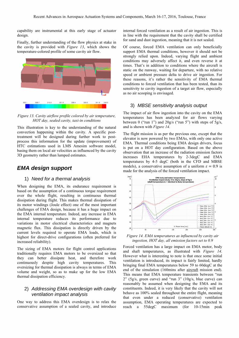
Finally, further understanding of the flow physics at stake in the cavity is provided with Figure 13, which shows the temperature-colored profile of some cavity air flow.
Figure 13. Cavity airflow profile colored by air temperature,
HOT day, sealed cavity, taxi-in conditions
This illustration is key to the understanding of the natural convection happening within the cavity. A specific post-treatment will be designed during further work to post-process this information for the update (improvement) of HTC estimations used in LMS Amesim software model, basing them on local air velocities as influenced by the cavity 3D geometry rather than lumped estimates.
EMA design support
1) Need for a thermal analysis
When designing the EMA, its endurance requirement is based on the assumption of a continuous torque requirement over the whole flight, resulting in continuous thermal dissipation during flight. This makes thermal dissipation of its motor windings (Joule effect) one of the most important challenges of EMA design, because it has a huge impact on the EMA internal temperature. Indeed, any increase in EMA internal temperature reduces its performance due to variations in motor electrical characteristics and magnets magnetic flux. This dissipation is directly driven by the current levels required to operate EMA loads, which is highest for direct-drive configurations (often preferred for increased reliability).
The sizing of EMA motors for flight control applications traditionally requires EMA motors to be oversized so that they can better dissipate heat, and therefore work continuously despite high cavity temperatures. This oversizing for thermal dissipation is always in terms of EMA volume and weight, so as to make up for the low EMA thermal dissipation efficiency.
2) Addressing EMA overdesign with cavity ventilation impact analysis
One way to address this EMA overdesign is to relax the conservative assumption of a sealed cavity, and introduce
internal forced ventilation as a result of air ingestion. This is in line with the requirement that the cavity shall be certified for sand and dust ingestion, meaning that it is not sealed.
Of course, forced EMA ventilation can only beneficially support EMA thermal conditions, however it should not be strongly relied upon. Indeed, varying flight and ambient conditions may adversely affect it, and even reverse it at times. That’s in addition to conditions where the aircraft is static on the runway, waiting for departure, with no relative speed or ambient pressure delta to drive air ingestion. For these reasons, it’s rather the sensitivity of EMA thermal conditions to forced ventilation that has been tested, than its sensitivity to cavity ingestion of a target air flow, especially as no air scooping is envisaged.
3) MBSE sensitivity analysis output
The impact of air flow ingestion into the cavity on the EMA temperatures has been analyzed for air flows varying between 0 (“run 1”) and 20g/s (“run 5”) with steps of 5g/s, and is shown with Figure 14.
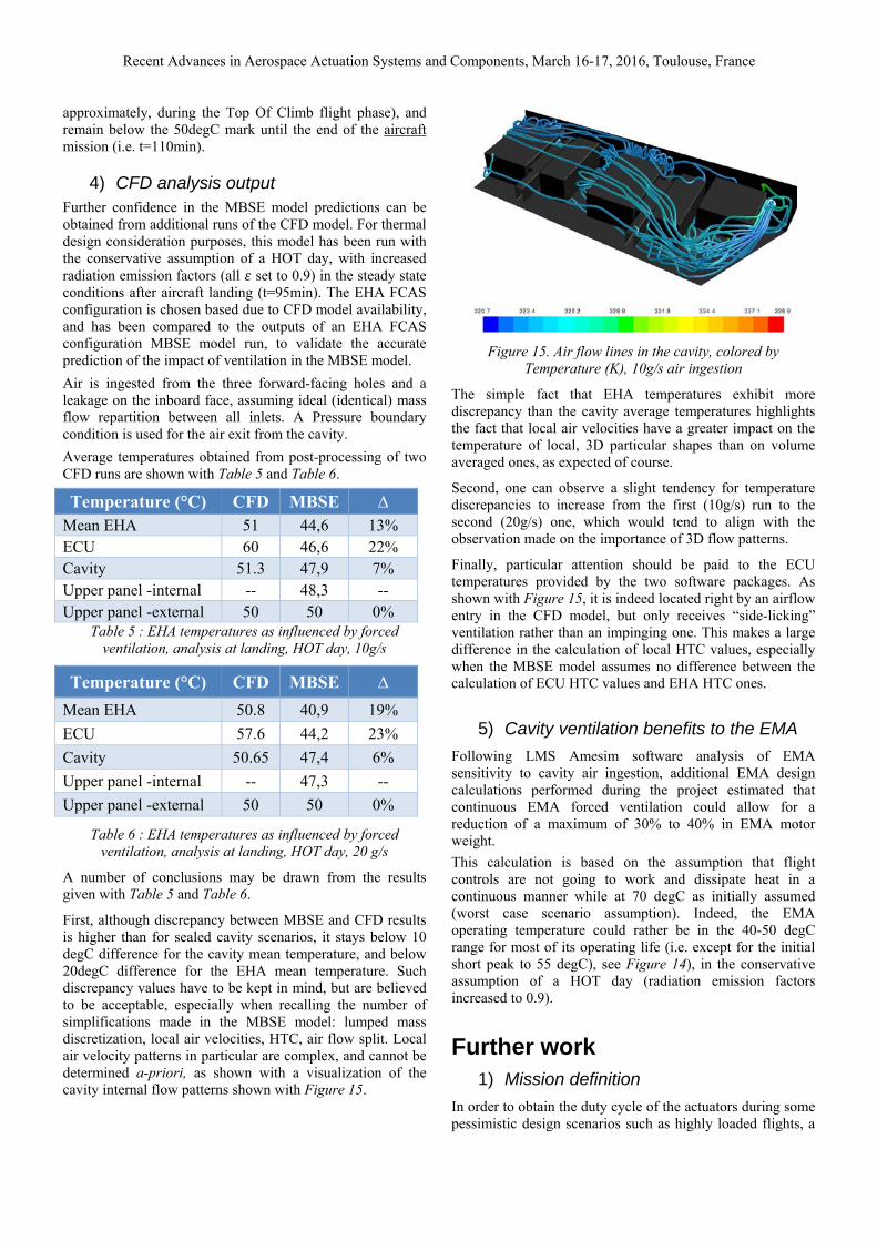
The flight mission is as per the previous one, except that the elevator is now powered by two EMAs, with only one active EMA. Thermal conditions being EMA design drivers, focus is put on a HOT day configuration. Based on the above observation that an increase of the radiation emission factors increases EHA temperatures by 2-3degC and EMA temperatures by 4-5 degC (both in the CFD and MBSE models), a conservative assumption of a uniform 0.9 is made for the analysis of the forced ventilation impact.
Figure 14. EMA temperatures as influenced by cavity air ingestion, HOT day, all emission factors set to 0.9
Forced ventilation has a large impact on EMA motor, body and shaft temperatures, as illustrated with Figure 14. However what is interesting to note is that once some initial ventilation is introduced, its impact is fairly limited, hardly bringing final EMA temperatures below 59 to 60degC at the end of the simulation (160mins after aircraft mission end). This means that EMA temperature transients between “run 2” (5g/s, green curve) and “run 3” (10g/s, blue curve) can reasonably be assumed when designing the EMA and its constituents. Indeed, it is very likely that the cavity will not behave as 100% sealed throughout the entire flight, meaning that even under a reduced (conservative) ventilation assumption, EMA operating temperatures are expected to reach a 55degC maximum (for 10-15min peak
Recent Advances in Aerospace Actuation Systems and Components, March 16-17, 2016, Toulouse, France
approximately, during the Top Of Climb flight phase), and remain below the 50degC mark until the end of the aircraft mission (i.e. t=110min).
4) CFD analysis output Further confidence in the MBSE model predictions can be obtained from additional runs of the CFD model. For thermal design consideration purposes, this model has been run with the conservative assumption of a HOT day, with increased radiation emission factors (all set to 0.9) in the steady state conditions after aircraft landing (t=95min). The EHA FCAS configuration is chosen based due to CFD model availability, and has been compared to the outputs of an EHA FCAS configuration MBSE model run, to validate the accurate prediction of the impact of ventilation in the MBSE model.
Air is ingested from the three forward-facing holes and a leakage on the inboard face, assuming ideal (identical) mass flow repartition between all inlets. A Pressure boundary condition is used for the air exit from the cavity.
Average temperatures obtained from post-processing of two CFD runs are shown with Table 5 and Table 6.
Temperature (°C) CFD MBSE ∆ Mean EHA 51 44,6 13% ECU 60 46,6 22% Cavity 51.3 47,9 7% Upper panel -internal -- 48,3 -- Upper panel -external 50 50 0%
Table 5 : EHA temperatures as influenced by forced ventilation, analysis at landing, HOT day, 10g/s
Temperature (°C) CFD MBSE ∆
Mean EHA 50.8 40,9 19%
ECU 57.6 44,2 23%
Cavity 50.65 47,4 6%
Upper panel -internal -- 47,3 --
Upper panel -external 50 50 0%
Table 6 : EHA temperatures as influenced by forced ventilation, analysis at landing, HOT day, 20 g/s
A number of conclusions may be drawn from the results given with Table 5 and Table 6.
First, although discrepancy between MBSE and CFD results is higher than for sealed cavity scenarios, it stays below 10 degC difference for the cavity mean temperature, and below 20degC difference for the EHA mean temperature. Such discrepancy values have to be kept in mind, but are believed to be acceptable, especially when recalling the number of simplifications made in the MBSE model: lumped mass discretization, local air velocities, HTC, air flow split. Local air velocity patterns in particular are complex, and cannot be determined a-priori, as shown with a visualization of the cavity internal flow patterns shown with Figure 15.
Figure 15. Air flow lines in the cavity, colored by Temperature (K), 10g/s air ingestion
The simple fact that EHA temperatures exhibit more discrepancy than the cavity average temperatures highlights the fact that local air velocities have a greater impact on the temperature of local, 3D particular shapes than on volume averaged ones, as expected of course.
Second, one can observe a slight tendency for temperature discrepancies to increase from the first (10g/s) run to the second (20g/s) one, which would tend to align with the observation made on the importance of 3D flow patterns.
Finally, particular attention should be paid to the ECU temperatures provided by the two software packages. As shown with Figure 15, it is indeed located right by an airflow entry in the CFD model, but only receives “side-licking” ventilation rather than an impinging one. This makes a large difference in the calculation of local HTC values, especially when the MBSE model assumes no difference between the calculation of ECU HTC values and EHA HTC ones.
5) Cavity ventilation benefits to the EMA
Following LMS Amesim software analysis of EMA sensitivity to cavity air ingestion, additional EMA design calculations performed during the project estimated that continuous EMA forced ventilation could allow for a reduction of a maximum of 30% to 40% in EMA motor weight.
This calculation is based on the assumption that flight controls are not going to work and dissipate heat in a continuous manner while at 70 degC as initially assumed (worst case scenario assumption). Indeed, the EMA operating temperature could rather be in the 40-50 degC range for most of its operating life (i.e. except for the initial short peak to 55 degC), see Figure 14), in the conservative assumption of a HOT day (radiation emission factors increased to 0.9).
Further work 1) Mission definition
In order to obtain the duty cycle of the actuators during some pessimistic design scenarios such as highly loaded flights, a

Recent Advances in Aerospace Actuation Systems and Components, March 16-17, 2016, Toulouse, France
«virtual» aircraft flight-record will also developed. It will include the influence of predefined turbulence, as well as some special maneuvers during flight (e.g. sudden altitude drop during cruise, s-maneuver just before landing and large turbulence levels) so as to put the actuation system into the most critical regime and make sure it will not generate overheat conditions in the cavity.
Finally, more diverse missions may be analyzed, with varied configurations, such as {EHA & EMA} for example. This will support MEA investigations in particular. More complexity can also be brought in with flight missions that include the failure of an actuator, or maximum loads applied to the surface as a result of a tear-down for example.
2) MBSE model
When enough CFD runs have been run, HTC variations may be characterized with dedicated Nu correlations that would be specific to the elevator cavity configuration and materials, and thus bring the 3D perspective and added value of CFD into the MBSE model. A simpler approach would consist in running smaller series of CFD runs (e.g. 4 runs) per flight phase (i.e. taxi-out / climb / cruise / descent / taxi-in) and capture HTC correlations specific to each aircraft phase only.
Similarly, it is planned to update the MBSE model with the radiation view factors generated by the 3D thermal model.
3) CFD model
The modeling of the thermal conduction within the cavity layers (currently based on the shell-conduction” approach) will be investigated for improvements. Particular attention will be paid to the impact it has on the cavity temperature.
The introduction of solid models of EHA and ECU into the CFD model will allow for the analysis of the impact of the aerothermal flow inside the cavity during a transient part of the flight mission, such as landing for example.
4) Testing for validation
In order to validate the MBSE and CFD models generated during this work, experimental testing of the “actuator in cavity” system is planned for execution by TsAGI. This test will rely on a full-scale composite stabilizer and the real EHA / EMA actuators installed inside the cavity.
Conclusions This collaboration between project partners allowed for the development of models that can reliably predict the influence of actuators design & characteristics (mass, dimensions) on the thermal behavior of the cavity they live in. This provides a better understanding of the thermal conditions they should be designed to operate in, even at early design stages.
As a result, these models and the verification methodology proposed allow actuation design engineers to account for system thermal considerations at early design stage, which is instrumental in supporting MEA applications development,
and is expected to eventually lead to aircraft lifecycle costs reduction through faster and better systems development.
Last but not least, the methodology developed gives the ability to all the project partners to merge and leverage the outputs of their work in the common LMS Amesim software platform. This makes it possible for them to focus on their core expertise (e.g. component development), while being confident that they can then analyze their design in a realistic context, with interfaces to other components being taken care of in the MBSE model. Of course, this model can be complemented with additional insight gained from CFD analysis, supporting flow pattern, local HTC, and radiation view factors identifications in particular. Once this additional insight is implemented into the MBSE model however, the MBSE model can be used as a standalone one, leveraging its flexibility and simulation power for further pre-design analyses.
REFERENCES Lawson, C.P., Pointon, J., “Thermal Management of
Electromechanical Actuation On An All-Electric Aircraft”, 26th ICAS Congress, Anchorage, Alaska. 14-19 Sept. 2008.
Van Den Bossche D., "The A380 flight control electrohydrostatic actuators, achievements and lessons learnt", ICAS 2006.
Incropera F.P., DeWitt D.P., (2002) Fundamentals of Heat and Mass Transfer, fifth edition, Jhon Wiley & Sons, Inc.
Saury D, Rouger N, Djanna F, Penot F, (2009), Mesures de vitesse, de température et de flux thermique en convection naturelle en espace confiné, CONGRES SFT 2009, May 2009, Vannes, France. 1, pp.129-134, 2009.
NOTATIONS abscoeff Surface absorption coefficient (null) ∆ Difference between two values (%) ε Radiation emission factor (null) λ Thermal conductivity (W/m/degC) φ Heat flow rate (W) σ Stefan-Boltzmann constant (W/m2/K4) θ Incidence angle (degrees) A Body surface (m2) F Radiation shape factor (null) L Distance (m) Nu Nusselt number (null) S Body surface (m2) T Temperature (°C)
ACKNOWLEDGEMENTS The authors wish to thank all the RESEARCH project partners for their participation and support.

Recent Advances in Aerospace Actuation Systems and Components, March 16-17, 2016, Toulouse, France
The authors would also like to express their gratitude to the European Commission and Russian Ministry of Trade and Industry for their support to the RESEARCH project.