Elementary Statics of 2 & Dimensions R.J.a. Barnard 1921
273
ttiittw, .tiiaannuiitiUiitnirHtmiiuRii, ^itiiiiiiiuiiiiiiiutiiiHiiHmiiiiiiii 3 1761 06705853 7 itiiittiitntiiiituHtiMitiHiUDintuitiitttiifHiUHiiiimiumt
-
Upload
bmover2933 -
Category
Documents
-
view
221 -
download
0
Transcript of Elementary Statics of 2 & Dimensions R.J.a. Barnard 1921
8/4/2019 Elementary Statics of 2 & Dimensions R.J.a. Barnard 1921
http://slidepdf.com/reader/full/elementary-statics-of-2-dimensions-rja-barnard-1921 1/272
ttiittw,
.tiiaannuiitiUiitnirHtmiiuRii,
^itiiiiiiiuiiiiiiiutiiiHiiHmiiiiiiii
3
1761
06705853
7
itiiittiitntiiiituHtiMitiHiUDintuitiitttiifHiUHiiiimiumt
ItllilltitiiiliilitiillliliililitHllltilililiillililiilliiiiiiiiit"""
•itiiitiinuiiiniintttiMiiiliiii
ilijilHIHHjll!
"
tiMiiiMinMi
8/4/2019 Elementary Statics of 2 & Dimensions R.J.a. Barnard 1921
http://slidepdf.com/reader/full/elementary-statics-of-2-dimensions-rja-barnard-1921 2/272
¥1
8/4/2019 Elementary Statics of 2 & Dimensions R.J.a. Barnard 1921
http://slidepdf.com/reader/full/elementary-statics-of-2-dimensions-rja-barnard-1921 3/272

8/4/2019 Elementary Statics of 2 & Dimensions R.J.a. Barnard 1921
http://slidepdf.com/reader/full/elementary-statics-of-2-dimensions-rja-barnard-1921 4/272
Digitized by tine Internet Arciiive
in 2007 witii funding from
IVIicrosoft Corporation
littp://www.arcliive.org/details/elementarystaticOObarnuoft
8/4/2019 Elementary Statics of 2 & Dimensions R.J.a. Barnard 1921
http://slidepdf.com/reader/full/elementary-statics-of-2-dimensions-rja-barnard-1921 5/272
ELEMENTARY STATICS
OFTWO
ANDTHREE DIMENSIONS
8/4/2019 Elementary Statics of 2 & Dimensions R.J.a. Barnard 1921
http://slidepdf.com/reader/full/elementary-statics-of-2-dimensions-rja-barnard-1921 6/272
MACMILLAN AND CO., Limited
LONDON • BOMBAY • CALCUTTA • MADRAS
MELBOURNE
THE MACMILLAN COMPANYNEW YORK • BOSTON • CHICAGO
DALLAS • SAN FRANCISCO
THE MACMILLAN CO. OF CANADA. Ltd.
TORONTO
8/4/2019 Elementary Statics of 2 & Dimensions R.J.a. Barnard 1921
http://slidepdf.com/reader/full/elementary-statics-of-2-dimensions-rja-barnard-1921 7/272
ELEMENTARY
STATICSOF TWO AND THREE DIMENSIONS
BY
R.J. A. BARNARD, MA. (Melb.)
PROFESSOR OF MATHEMATICS, ROYAL MILITARY COLLEGE OF AUSTRALIA
MACMILLAN AND CO., LIMITEDST. MARTIN'S STREET, LONDON
1921
8/4/2019 Elementary Statics of 2 & Dimensions R.J.a. Barnard 1921
http://slidepdf.com/reader/full/elementary-statics-of-2-dimensions-rja-barnard-1921 8/272
COPTRIOBT
OUABGOW PRINTED AT THK tJMIVERSITT PRESS
. BV ROUKKT MACLKH08K AND CO. LTD.
8/4/2019 Elementary Statics of 2 & Dimensions R.J.a. Barnard 1921
http://slidepdf.com/reader/full/elementary-statics-of-2-dimensions-rja-barnard-1921 9/272
PREFACE
The reception of my Elementary Dynamics has encouraged
me to write a Statics of a similar standard of difficulty,
and I have followed the same principles as in that book.
With reference to the contents I may mention the following :
(i) The introduction of examples on friction early, in
dealing with forces at a point,
(ii) The insertion of a chapter on Shearing Stress and
Bending Moments,
(iii) The use of the methods of the elementary difEerential
calculus in the chapteron
VirtualWork, and of
the integral calculus for finding the centres of
mass of a number of geometrical areas and volumes,
(iv) Three-Dimensional Statics are dealt with more fully
than usual,
(v) A chapter on Vectors in Space, including vector
products, has been included.
It is hoped that the last-named chapter, with the chapter
on vectors in my Dynamics, will make a satisfactory introduc-
tion to Vector Algebra and its applications.
As in my Dynamics, a number of the more difficult examples
come from papers set at the Melbourne University. Nearly
all the others have been constructed by myself for the book
or for my classes.
R J. A. BARNARD.DUNTROON,
March, 1921.

8/4/2019 Elementary Statics of 2 & Dimensions R.J.a. Barnard 1921
http://slidepdf.com/reader/full/elementary-statics-of-2-dimensions-rja-barnard-1921 10/272
8/4/2019 Elementary Statics of 2 & Dimensions R.J.a. Barnard 1921
http://slidepdf.com/reader/full/elementary-statics-of-2-dimensions-rja-barnard-1921 11/272
CONTENTS
CHAPTER PAGE
I. Foundations of Mechanics 1
II. Forces at a Point - 8
III. Parallel Forces 39
IV. Work. Simple Machines - - • - 62
V. Couples. Any Forces in a Plane ... 79
VI. Connected Bodies - - - - - - - 107
VII. Weightless Rods, Frames. Graphical Statics ofWeightless Frames - - - - - 119
VIII. Shearing Stress and Bending Moment - - 135
IX. Miscellaneous Questions 147
/
X. Centres op Mass - - - - - - -161
XI. Virtual Work 187
XII. Graphical Statics 200
XIII. Forces at a Point in Three Dimensions - - 209
XIV. Any Forces in Three Dimensions - - - 215
XV. Vectors in Space - 238
Appendix ^ - - - - 246
Answers - 247

8/4/2019 Elementary Statics of 2 & Dimensions R.J.a. Barnard 1921
http://slidepdf.com/reader/full/elementary-statics-of-2-dimensions-rja-barnard-1921 12/272
8/4/2019 Elementary Statics of 2 & Dimensions R.J.a. Barnard 1921
http://slidepdf.com/reader/full/elementary-statics-of-2-dimensions-rja-barnard-1921 13/272
CHAPTER I
FOUNDATIONS OF MECHANICS.
Before dealing specially with Statics as one branch of
Mechanics, it is necessary to refer to the fundamental ideas
about Force, and these are most easily obtained from a con-
sideration of dynamical questions.
It will be sufficient to give a short summary of these ideas,
referring for fuller development to my book on Elementary
Dynamics, Chapter III.
1. Position, Relative Motion and Best.
The position of a point is generally measured by its distances
from points, or lines, or planes fixed to the earth. If these
distances change, it is said to be in motion relative to the
earth ; if the distances do not change it is at rest relative
to the earth. When it is at rest relative to the earth it is usually
said simply to be at rest.
2. Force.
Force is generally defined as any action that alters or tends
to alter a body's state of motion ; but two or more forces
acting on a body may balance one another's effects in such a
way that the body remains at rest.
Statics is that branch of mechanics which deals with the
relations between forces acting on a body at rest.
8/4/2019 Elementary Statics of 2 & Dimensions R.J.a. Barnard 1921
http://slidepdf.com/reader/full/elementary-statics-of-2-dimensions-rja-barnard-1921 14/272
2 ELEMENTARY STATICS
A body is said to be Rigid if its shape and size are unaffected
by forces acting on it. While no such body actually exists in
nature, the alterations in solids are small and will be neglected
throughout this book, except where changes are specially
mentioned, such as in the springs and strings of the next
paragraphs.
In simple experiments a force may be applied to a body
by attaching a spring or string to it, and pulling the spring
or string. The effect of the force depends both on the strength
and the direction of the pull. Hence a force requires bothmagnitude and direction to denote it fully, and can be con-
sequently represented by a straight line whose length repre-
sents the magnitude of the force according to some scale,
and whose direction is the direction of the force.
If the force is exerted by the medium of a spiral spring
(spring balance), the extension of the spring can be taken as
a measure of the force. For, if we take weights which balance
on an ordinary balance, and hang them successively to a
spring balance, we find that they elongate the spring balance
to the same amount ; and that if different weights are hung
on, the elongation will be very nearly proportional to the
weight, and even if the elongation is not exactly proportional
to the weight, the balance may still be graduated to shew
various forces by marking the positions taken by the pointer
for given weights hung on the balance.
Spring balances thus graduated, and of comparatively
small stiffness, so that a weight of a few ounces produces an
easily observed elongation, may be used for simple demonstra-
tions of fundamental results in statics.
3. Action and Reaction.
A force acting on a body is always due to the presence of a
second body influencing it, and a force never acts on one
body without an equal force acting in the opposite direction
I
8/4/2019 Elementary Statics of 2 & Dimensions R.J.a. Barnard 1921
http://slidepdf.com/reader/full/elementary-statics-of-2-dimensions-rja-barnard-1921 15/272
FOUNDATIONS OF MECHANICS 3
on the second. This fact is called Newton's Law of Action
and Reaction.
For example, when a heavy body rests on a horizontal table,
the body presses down on the table, and the table presses
upwards on the body with exactly the same force. A verifica-
tion of this law in certain cases may be made by means of the
spring balances. If twoi of these are hooked together and
then pulled, it will be found that the two register the same
force, shewing that they exert the same force to one another.
As a general rule, the bodies acting and re-acting on one another
are in contact, as in the above cases, but all bodies also act
on one another by gravitational attraction, and in this case
the two reacting bodies pull one another without contact.
This force, however, is only appreciable in ordinary statics
when one of the bodies is the earth, the gravitational attraction
between two bodies on the earth being always very minute.
4. Weight.
The attraction which the earth exerts on a body results
in the body having weight.
Weight is the force with which a body presses on a horizontal
plane on which it is at rest, or the force with which a body
at rest, and supported at one point (for example by a string),
will exert on its support.
On account of the rotation of the earth, thig is slightly
less than the force with which the earth attracts the body
(see Elementary Dynamics, Art. 130). However, it is not
necessary in Statics to consider the rotation of the earth, if
we replace the attraction of the earth by a slightly different
force equal to the weight of the body ; in other words, if wethink of the body as acted on by a vertical downward force
equal to its weight. This force, and the other forces acting
on the body, will balance one another in the sense referred
to above (Art. 2), as if there were no rotation of the earth.
8/4/2019 Elementary Statics of 2 & Dimensions R.J.a. Barnard 1921
http://slidepdf.com/reader/full/elementary-statics-of-2-dimensions-rja-barnard-1921 16/272
4 ELEMENTARY STATICS
5. Transmissibility of Force.
The principle called the Transmissibility of Force states
that a force may be supposed to act at any point in its line of
action, or in other words, the effect on a body is the same at
whatever point in the line of action the force is applied to the
body.
Thus, if we have a block of wood on a horizontal table,
it will take the same force to move it, whether we pull it from
the front or push it from behind, provided the line of action
of the pull
andpush is the same.
6. Compounding of Two Forces.
Besides the Laws of Action and Reaction, and of the
Transmissibility of Force, Statics requires another experi-
mental basis to rest on. This is the rule or rules concerning
the combined action of two forces meeting at one point.
The facts may be expressed in two statements :
(I) If two forces P and Q act along the same line in the
same direction, they are equivalent in their effect to a single
force equal to their sum, and if they act in opposite directions
they are equivalent to a single force equal to their difference,
in the direction of the larger.
In particular, if two equal forces act on a body in opposite
directions, along the same line, the body can remain at rest
and convergely, if a body remains at rest under the action of
two forces only, the forces must be
equal, opposite, and in the same
straight line.
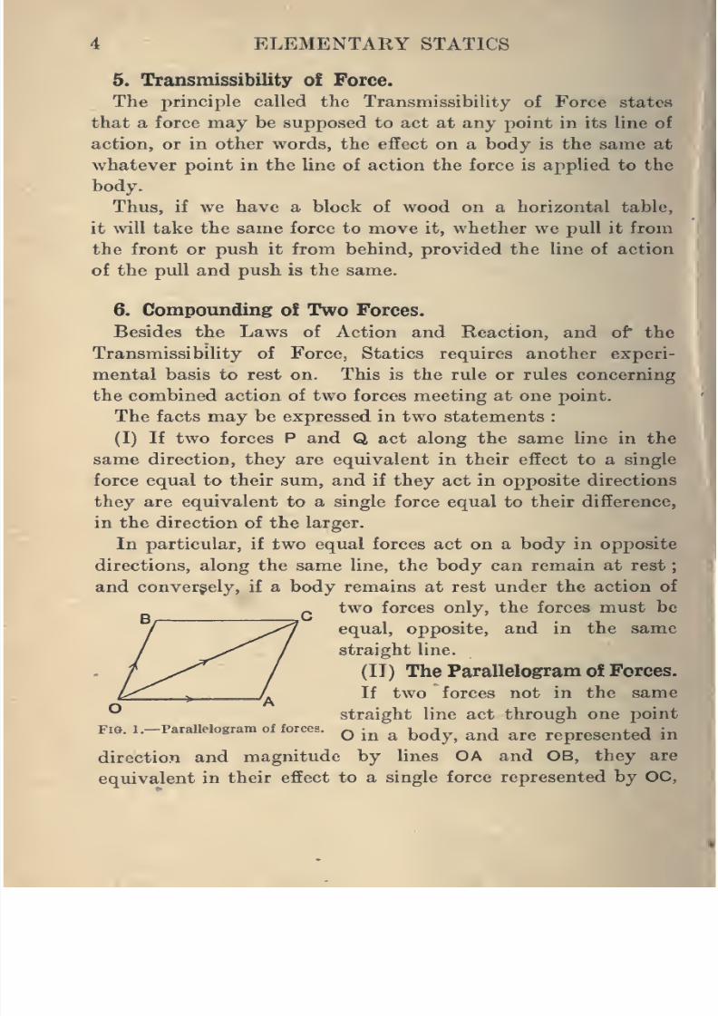
(11) The Parallelogram of Forces.
If two forces not in the same^straight line act through one point
Fio.l.-ParaUelogram of forces, q -^ ^ ^^^^^ ^^^ ^^^ represented in
direction and magnitude by lines OA and OB, they are
equivalent in their effect to a single force represented by OC,
8/4/2019 Elementary Statics of 2 & Dimensions R.J.a. Barnard 1921
http://slidepdf.com/reader/full/elementary-statics-of-2-dimensions-rja-barnard-1921 17/272
FOUNDATIONS OF MECHANICS
the diagonal of the parallelogram of which OA and OB are
adjacent sides.
The first of these statements, relating to forces in the same
line, may be regarded as a special case of the parallelogram
of forces.
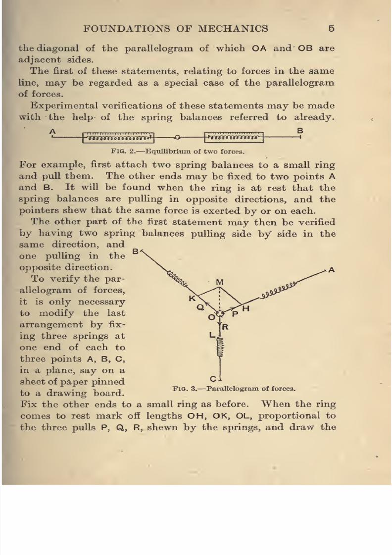
Experimental verifications of these statements may be made
with the help of the spring balances referred to already.
AI
, ,,
|n^^nn^nn^mnn^^_^S' hQ(WjymnrsT!nmnw O HTfirtrwriTSTM 1
Fig. 2.
—Equilibrium of two forces.
For example, first attach two spring balances to a small ring
and pull them. The other ends may be fixed to two points A
and B, It will be found when the ring is at rest that the
spring balances are pulling in opposite directions, and the
pointers shew that the same force is exerted by or on each.
The other part of the first statement may then be verified
by having two spring balances pulling side by side in the
same direction, and
one pulling in the
opposite direction.
To verify the par-
allelogram of forces,
it is only necessaryto modify the last
arrangement by fix-
ing three springs at
one end of each to
three points A, B, C,
in a plane, say on a
sheet of paper pinned
to a drawing board.
Fix the other ends to a small ring as before. When the ring
comes to rest mark off lengths OH, OK, OL, proportional to
the three pulls P, Q, R, shewn by the springs, and draw the
FlQ. 3.-Ci
-Parallelogram of forces.
8/4/2019 Elementary Statics of 2 & Dimensions R.J.a. Barnard 1921
http://slidepdf.com/reader/full/elementary-statics-of-2-dimensions-rja-barnard-1921 18/272
6 ELEMENTARY STATICS
parallelogram OHMK. Then it will be found that OM is in the
same line as OL, and equal to OL. This shews that since R
balances a force equivalent to P and Q, therefore the forces P
and Q represented by OH and OK are together equivalent to
a force represented by OL.
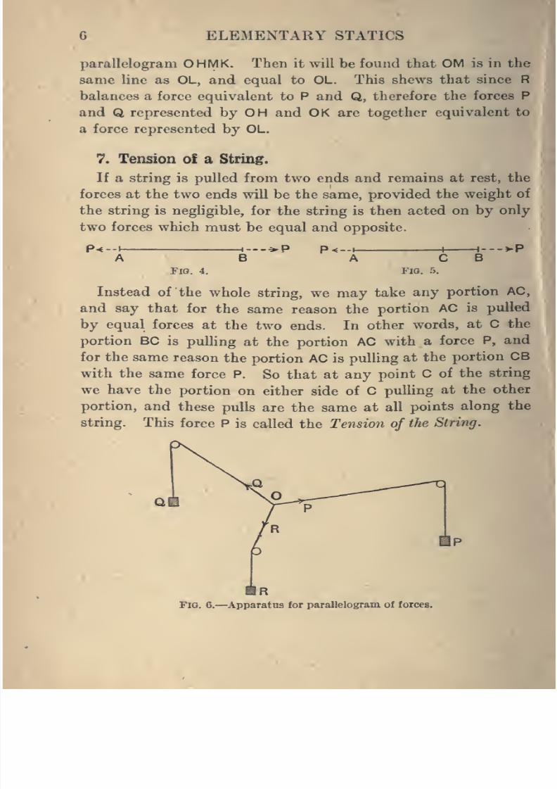
7. Tension of a String.
If a string is pulled from two ends and remains at rest, the
forces at the two ends will be the same, provided the weight of
the string is negligible,for the string
is
then acted on byonly
two forces which must be equal and opposite.
Pt-y- H-.-*P P<--t- H---J-P
Fia. 4. Fio. 5.
Instead of the whole string, we may take any portion AC,
and say that for the same reason the portion AC is pulled
by equal forces at the two ends. In other words, at C the
portion BC is pulling at the portion AC with a force P, and
for the same reason the portion AC is pulling at the portion CB
with the same force P. So that at any point C of the string
we have the portion on either side of C pulling at the other
portion, and these pulls are the same at all points along the
string. This force P is called the Tension of the Siring.
Fig. 6.—Apparatus for parallelogram of forces.
8/4/2019 Elementary Statics of 2 & Dimensions R.J.a. Barnard 1921
http://slidepdf.com/reader/full/elementary-statics-of-2-dimensions-rja-barnard-1921 19/272
FOUNDATIONS OF MECHANICS 7
The same result applies to a weightless string passing round
a frictionless peg or pulley.
Thus, in the verification of the parallelogram of forces the
strings may be replaced by strings passing over smooth pulleys
and having weights attached at the ends, as in Fig. 6.
The pulleys are in a vertical plane, and if the strings are
knotted at O or attached to a small ring there, we have three
forces P, Q, R, acting at O in the directions shewn, and the
parallelogram of forces may be verified as before.
8. Units of Force.
In all the Statics it is only ratios of the forces that come
into the equations, hence there are no difficulties about units
such as appear in the Dynamics ; consequently, in Statics the
forces may be measured in any unit so long as the same unit
is retained throughout the one question. We will use the
Pound-weight, Gram-weight, or Kilogram-weight as our usual
units.
8/4/2019 Elementary Statics of 2 & Dimensions R.J.a. Barnard 1921
http://slidepdf.com/reader/full/elementary-statics-of-2-dimensions-rja-barnard-1921 20/272
CHAPTER II.
FORCES AT A POINT.
9. Two Forces.
We have seen that when a body is acted on by two forces
only and at rest, these forces must be equal, opposite, and in
the same straight line.
In such a case it is said that the body is in equilibrium, or
that the forces are in equilibrium. Both expressions are in
common use.
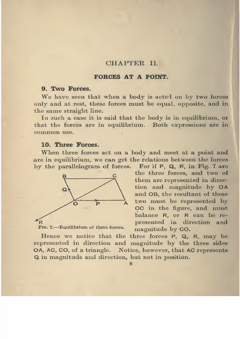
10. Three Forces.
When three forces act on a body and meet at a point and
are in equilibrium, we can get the relations between the forces
by the parallelogram of forces. For if P, Q, R, in Fig. 7 are
the three forces, and two of
them are represented in direc-
tion and magnitude by OAand OB, the resultant of these
two must be represented by
OC in the figure, and must
balance R, or R can be re-
presented in direction and
magnitude by CO.
Hence we notice that the three forces P, Q, R, may be
represented in direction and magnitude by the three sides
OA, AC, CO, of a triangle. Notice, however, that AC represents
Q, in magnitude and direction, but not in position.
8
Fig. 7.—Equilibrium of three forces.
8/4/2019 Elementary Statics of 2 & Dimensions R.J.a. Barnard 1921
http://slidepdf.com/reader/full/elementary-statics-of-2-dimensions-rja-barnard-1921 21/272
FORCES AT A POINT 9
We thus get the proposition known as the Triangle of Forces,
namely :
//three forces acting at a 'point can he represented in direction
and magnitude hy the three sides of a triangle taken in order
{that is, in order round the triangle as OA, AC, CO), they are
in equilibrium ; and conversely,
// three forces acting at a point are in equilibrium, they can
be represented by the three sides of a triangle taken in order.
It will be noticed that the three lines of action of the forces
must be in one plane ; also that if three forces in one plane
are in equilibrium, they must all meet in a point or be all
parallel.
For if any two of them, say P and Q, meet in a point O,
the resultant of P and Q acts through O, and can only be
balanced by a single force if this force acts through O.
We shall find later that if two forces are parallel, they can
be balanced by a third force parallel to these and in the same
plane ; also that three forces, which are not in the same plane,
cannot balance one another.
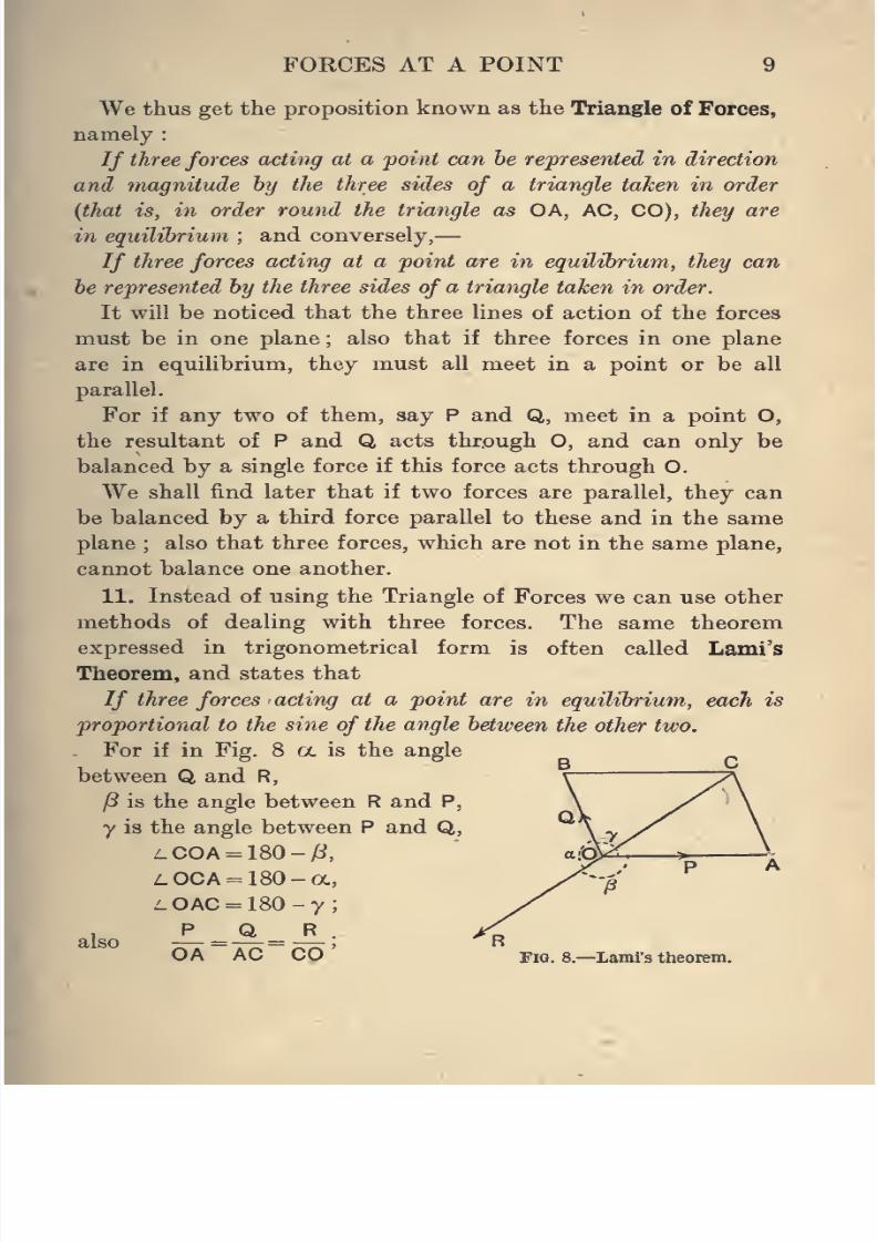
11. Instead of using the Triangle of Forces we can use other
methods of dealing with three forces. The same theorem
expressed in trigonometrical form is often called Lami's
Theorem,and
states that
// three forces acting at a point are in equilibrium, each is
proportional to the sine of the angle between the other two.
For if in Fig. 8 a is the angle
between Q and R,
/3 is the angle between R and P,
y is the angle between P and Q,
^COA = 180-/i,
z.OCA = 180-oc,
L OAC = 180 - 7 ;
also A=A=_?_-OA AC CO Fig. 8.—Lami's theorem.
8/4/2019 Elementary Statics of 2 & Dimensions R.J.a. Barnard 1921
http://slidepdf.com/reader/full/elementary-statics-of-2-dimensions-rja-barnard-1921 22/272
10 ELEMENTARY STATICS
and by trigonometry,
OA AC CO
sin (180 -a) sin (180-^3) sin (180 -y)
. OA AC . CO
sin fd sin y
Q R
sin^
sinoc
P
sma siny
also
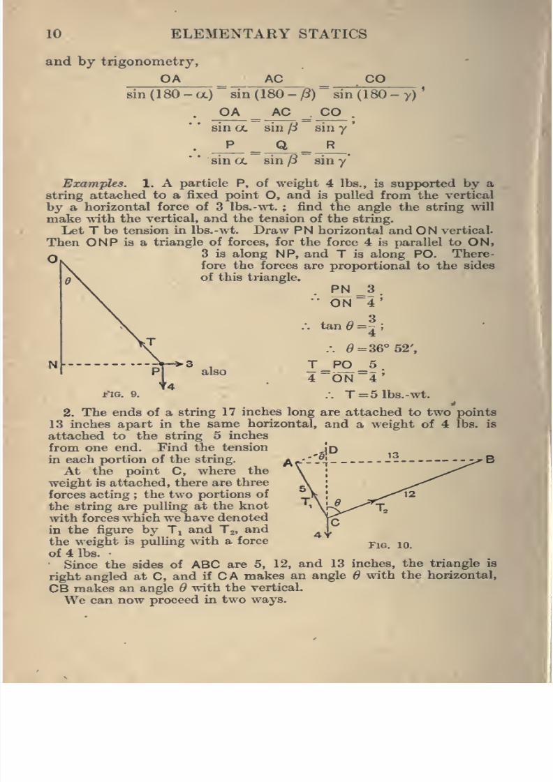
Examples. 1. A particle P, of weight 4 lbs., is supported by a
string attached to a fixed point O, and is pulled from the vertical
by a horizontal force of 3 Ibs.-wt. ; find the angle the string will
make -nath the vertical, and the tension of the string.
Let T be tension in Ibs.-wt. Draw PN horizontal and ON vertical.
Then ONP is a triangle of forces, for the force 4 is parallel to ON,3 is along NP, and T is along PO. There-
fore the forces are proportional to the sides
0\ of this triangle.
PN^3.0N~4'
.-. tan<9=f;4
.-. e=36°52',
TPO 5.
4~ON~4'.-. T=51bs.-wt.
2. The ends of a string 17 inches long are attached to two points
13 inches apart in the same horizontal, and a weight of 4 lbs. is
attached to the string 5 inches
from one end. Find the tension
in each portion of the string.
At the point C, where the
weight is attached, there are three
forces acting ; the two portions of
the string are pulling at the knot
with forces which we have denoted
in the figure by T^ and Tj, and
the weight is pulling with a force
of 4 lbs.
Since the sides of ABC are 5, 12, and 13 inches, the triangle is
right angled at C, and if C A makes an angle 6 with the horizontal,
CB makes an angle 6 ynth the vertical.
We can now proceed in two ways.
8/4/2019 Elementary Statics of 2 & Dimensions R.J.a. Barnard 1921
http://slidepdf.com/reader/full/elementary-statics-of-2-dimensions-rja-barnard-1921 23/272
FORCES AT A POINT 11
First solution, by the Triangle of Forces.
To get a convenient triangle with its sides parallel to the three
forces, draw AD parallel to CB, and CD vertical ; then ADC has its
sides parallel to the three forces, following round the triangle inthe direction ADC A. The forces Tj, Tj, and 4 are therefore pro-
portional to CA, AD, DC.
Now the triangle ADC is similar to CAB.
CA^AD^DC,12" 5 ""is
'
•12 5 13'
48.-, Tt=^= 3-69 lbs.-wt.
and To= 7^= 1-54 lbs.-wt.^ 13
Second solution, by LarnVs Theorem.
The angles between the forces are
180 - ^ between Tg and 4,
90 + ^ between Tj and 4,
90 between T^ and Tg
T,
but
3. A string of length 24 inches has its ends fixed to two points
20 inches apart in the same horizontal line, and a weight of 6 lbs.
is hung from it by means of a small hook. Find the tension of the
string. (Neglect friction ; see Art. 18.)
The difference between this and Example 2 is that the hook
can slip along the string, and the two portions of the string form
one continuous string with the same tension throughout. In
Example 2, the two portions being knotted to the third were equiva-
lent to two quite distinct strings with different tensions.
As the tensions are the same, either Lami's Theorem or the
parallelogram of forces shews that the two portions make equal
sir1(180 -0)- sin (90+ ^)" sin 90'
T,
sin 6
_ T2_
cos^
4
= 1'
sin 6
12
"13 and cos^:
5
~13'
T,48
'~13 lbs.-wt., T2 =
20
"13 lbs.-•wt.
8/4/2019 Elementary Statics of 2 & Dimensions R.J.a. Barnard 1921
http://slidepdf.com/reader/full/elementary-statics-of-2-dimensions-rja-barnard-1921 24/272
12 ELEMENTARY STATICS
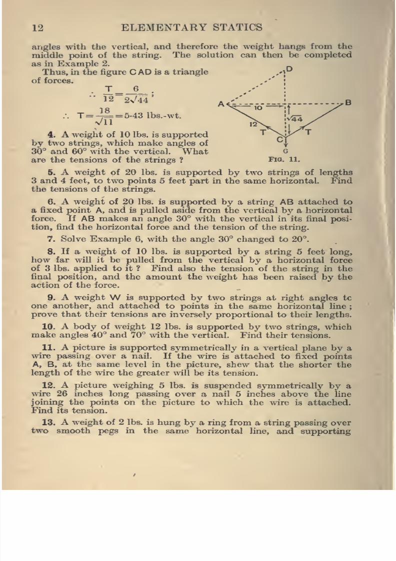
angles with the vertical, and therefore the weight hangs from the
middle point of the string. The solution can then be completed
as in Example 2.
Thus, in the figure
CADis a triangle .'P
of forces.
T^_6_." 12 2^44
.-. 7=4^ = 5-43 lbs.-wt.
Vll
4. A weight of 10 lbs. is supported
by two strings, which make angles of
30° and 60° with the vertical. Whatare the tensions of the strings ?
5. A weight of 20 lbs. is supported by two strings of lengths
3 and 4 feet, to two points 5 feet part in the same horizontal. Kndthe tensions of the strings.
6. A weight of 20 lbs. is supported by a string AB attached to
a fixed point A, and is pulled aside from the vertical b}' a horizontal
force. If AB makes an angle 30° with the vertical in its final posi-
tion, find the horizontal force and the tension of the string.
7. Solve Example 6, with the angle 30° changed to 20°.
8. If a weight of 10 lbs. is supported by a string 5 feet long,
how far will it be pulled from the vertical by a horizontal force
of 3 lbs. applied to it ? Find also the tension of the string in the
final position, and the amount the weight has been raised by the
action of the force.
9. A weight W is supported by two strings at right angles tc
one another, and attached to points in the same horizontal line ;
prove that their tensions are inversely proportional to their lengths.
10. A body of weight 12 lbs. is supported by two strings, which
make angles 40° and 70° with the vertical. Find their tensions.
11. A picture is supported sjinmetrically in a vertical plane by awire passing over a nail. If the wire is attached to fixed points
A, B, at the same level in the picture, shew that the shorter the
length of the wire the greater wiU. be its tension.
12. A picture weighing 5 lbs. is suspended symmetrically by a^vire 26 inches long passing over a nail 5 inches above the line
joining the points on the picture to which the wire is attached.
Find its tension.
13. A weight of 2 lbs. is himg by a ring from a string passing over
two smooth pegs in the same horizontal Une, and supporting
I
8/4/2019 Elementary Statics of 2 & Dimensions R.J.a. Barnard 1921
http://slidepdf.com/reader/full/elementary-statics-of-2-dimensions-rja-barnard-1921 25/272
FOECES AT A POINT 13
weights of 1| lbs. at each end. Find the angles the Inclined portions
of the string make with the vertical.
Will the result be affected if one of the pegs is placed at a higher
level than the other ?
14. A string passes over two smooth pegs on the same level and
supports weights of 5 lbs. at each end. A weight of 6 lbs. is nowhung to it midway between the pegs, and the point of attachment
of this weight moves down 3 inches. Find the distance between the
pulleys, and find the depth of the middle point below them when
any weightW is hung on.
Examine the case whenW =8. What happens ifW = 10 lbs. ?
15. If three forces, of magnitudes 3, 4, 5 Ibs.-wt., are in equilibrium,
find by the triangle of forces the angles between each pair.
16. If three forces, of magnitudes 5, 6, 7 Ibs.-wt., are in equilibrium,
find by the triangle of forces the angles between each pair.
12. Resultant and Components.
The force R, which is equivalent in its action to two given
forces P and Q, is called their Resultant, and P and Q are called
the Components of R.
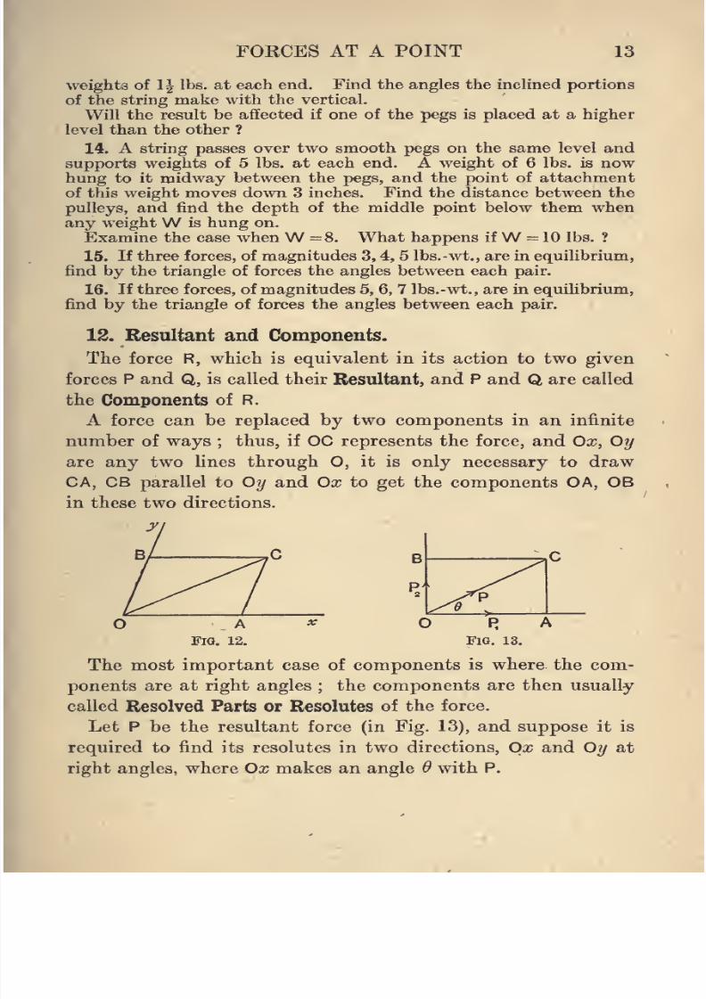
A force can be replaced by two components in an infinite
number of ways ; thus, if OC represents the force, and Ox, Oy
are any two lines through O, it is only necessary to draw
CA, CB parallel to Oy and Ox to get the components OA, OB
in these two directions.
The most important case of components is where the com-
ponents are at right angles ; the components are then usually
called Resolved Parts or Resolutes of the force.
Let P be the resultant force (in Fig. 13), and suppose it is
required to find its resolutes in two directions, Ox and Oy at
right angles, where Ox makes an angle 6 with P.
8/4/2019 Elementary Statics of 2 & Dimensions R.J.a. Barnard 1921
http://slidepdf.com/reader/full/elementary-statics-of-2-dimensions-rja-barnard-1921 26/272
14 ELEMENTARY STATICS
Let Pi and P^ be the resolutes. Then, in the figure,
P, OA .
P
Pg
P
Pi
OC
OBACOC ~ OC
Pcos^, (1)
> sin ^
also
and
P2 = Psin ^;
OA2 + OB2 = OC2;
P2....^^ + Po^-
P2 AC . .
zr = :=nr = tan 6.
Pi OA
•(2)
(3)
(4)
(1) and (2) give the resolutes in two directions at right
angles when the magnitude and direction of the resultant
are given; (3) and (4) give the magnitude and direction of
the resultant when the resolut.es in two directions at right
angles are given.
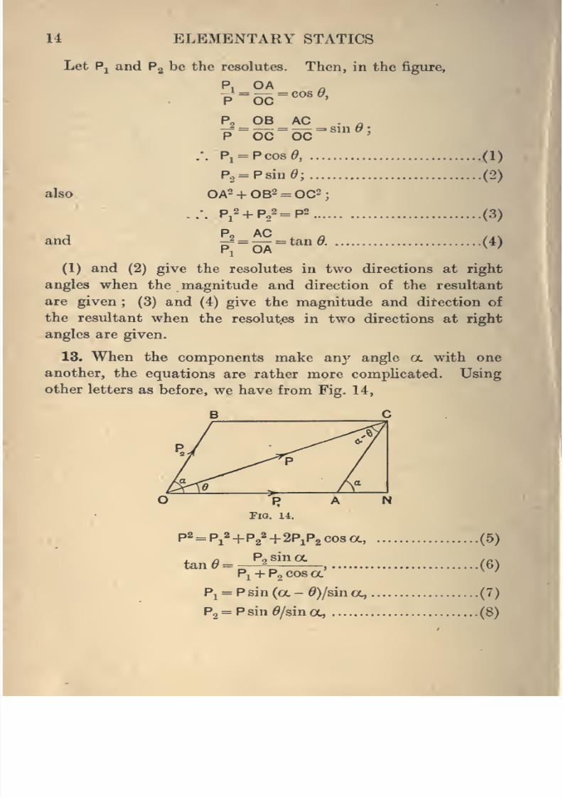
13. When the components make anj'^ angle a. with one
another, the equations are rather more complicated. Using
other letters as before, we have from Fig. 14,
FIO. 14.
p2 = Pj2+ p^2^ 2P1P2 cos a,
, ^ Po sin OCta,nO =
Pi + Pgcosoc'
Pj = P sin (oc - 0)/sin a,
Pg = P sin ^/sin oc,
8/4/2019 Elementary Statics of 2 & Dimensions R.J.a. Barnard 1921
http://slidepdf.com/reader/full/elementary-statics-of-2-dimensions-rja-barnard-1921 27/272
FORCES AT A POINT 15
all following from elementary trigonometry. They should
be verified by the student.
Example. Shew that equations (5)-(8) reduce to (l)-(4) if a. is
a right angle.
14. It is important to observe that the resolute of a force
in any direction is obtained by multiplying theforce by the cosine
of the angle between it and the given direction.
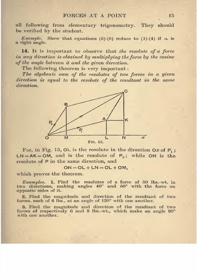
The following theorem is very important
The algebraic
sum ofthe resolutes
of two forcesin a given
direction is equal to the resolute of the resultant in the same
direction.
C
Fig. 15.
For, in Fig. 15, OL is the resolute in the direction Ox of Pj
LN=AK = OM, and is the resolute of P^; while ON is the
resolute of P in the same direction, and
ON = OL+LN = OL + OM,
which proves the theorem.
Examples. 1. Find the resolutes of a force of 50 Ibs.-wt. in
two directions, making angles 40° and 50° with the force on
opposite sides of it.
2. Find the magnitude and direction of the resultant of two
forces, each of 6 lbs., at an angle of 120° with one another.
3. Find the magnitude and direction of the resultant of two
forces of respectively 6 and 8 Ibs.-wt., which make an angle 60°
with one another.
8/4/2019 Elementary Statics of 2 & Dimensions R.J.a. Barnard 1921
http://slidepdf.com/reader/full/elementary-statics-of-2-dimensions-rja-barnard-1921 28/272
16 ELEMENTARY STATICS
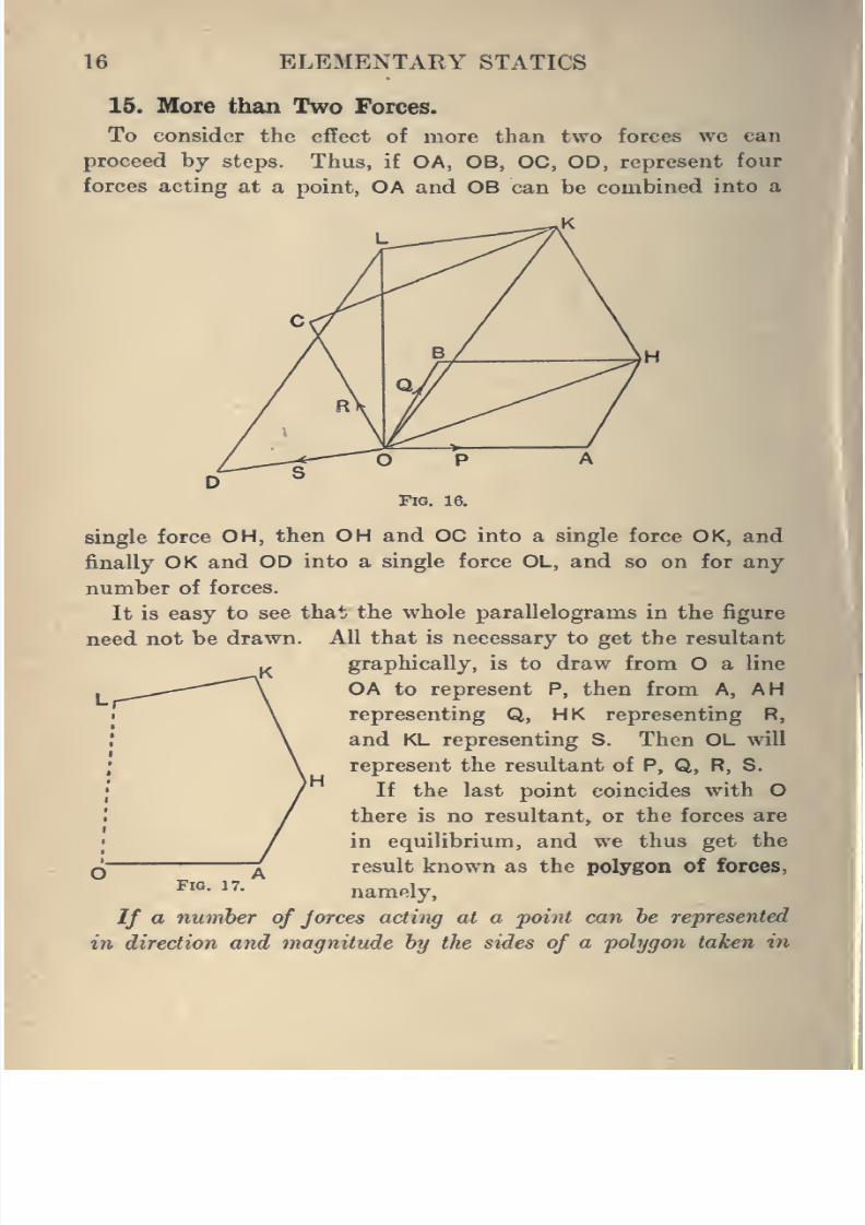
15. More than Two Forces.
To consider the effect of more than two forces we can
proceed by steps. Thus, if OA, OB, OC, OD, represent fourforces acting at a point, OA and OB can be combined into a
single force OH, then OH and OC into a single force OK, and
finally OK and OD into a single force OL, and so on for any
number of forces.
It is easy to see that the whole parallelograms in the figure
need not be drawn. All that is necessary to get the resultant
graphically, is to draw fromO
a line
OA to represent P, then from A, AH
representing Q, HK representing R,
and KL representing S. Then OL will
represent the resultant of P, Q, R, S.
If the last point coincides with O
there is no resultant, or the forces are
in equilibrium, and we thus get the
result known as the polygon of forces,
namely.
If a number of jorces acting at a -point can he represented
in direction and magnitude hy the sides of a polygon taken in
Fig. 17.
8/4/2019 Elementary Statics of 2 & Dimensions R.J.a. Barnard 1921
http://slidepdf.com/reader/full/elementary-statics-of-2-dimensions-rja-barnard-1921 29/272
FORCES AT A POINT 17
order, the forces are in equilibrium ; and conversely, if they are
in equilibrium, they can be represented by the sides of a polygon
taken in order.
Notice, however, that when there are more than three
forces whose directions are known, the relative magnitudes
cannot be deduced by the polygon of forces, as it can when
there are only three forces, for different polygons may have
their sides in given directions and
yet not be similar, as, for example,
a square and a rectangle.
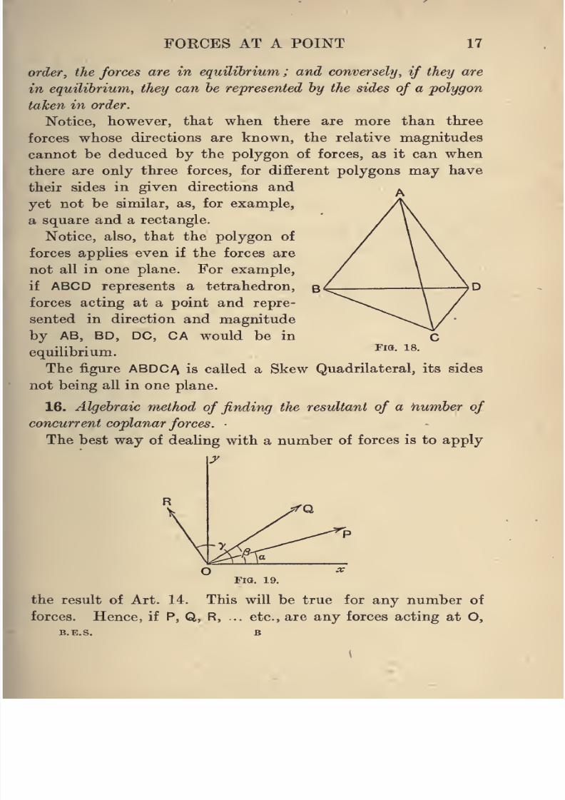
Notice, also, that the polygon of
forces applies even if the forces are
not all in one plane. For example,
if ABCD represents a tetrahedron,
forces acting at a point and repre-
sented in direction and magnitude
by AB, BD, DC, CA would be in
equilibrium.
The figure ABDC^ is called a Skew Quadrilateral, its sides
not being all in one plane.
16. Algebraic method of finding the resultant of a number of
concurrent coplanar forces.
The best way of dealing with a number of forces is to apply
y
Fia. 18.
FlO. 19.
the result of Art. 14. This will be true for any number of
forces. Hence, if P, Q, R, .. etc., are any forces acting at O,
B.E.S. B
K

8/4/2019 Elementary Statics of 2 & Dimensions R.J.a. Barnard 1921
http://slidepdf.com/reader/full/elementary-statics-of-2-dimensions-rja-barnard-1921 30/272
18 ELEMENTARY STATICS
and making angles a, /3, y, ... etc., with a line Ox, and if the
resultant is F, making an angle 6 with Ox, and if X, Y are the
resolutes of F along and perpendicular to Ox, then
X = F cos ^ = P cos a.+ Q cos ^ + R cos 7+ . .
.
and Y = Fsin d = P sin rx+ Q sin/?+ R siny+...
from which F and 6 can be found.
If the forces are in equilibrium,
F = 0;
.*. both X and Y are zero.
17. Conditions for Equilibrium.
We can now state the conditions for equilibrium of a number
of concurrent coplanar forces, thus :
The forces are in equilibrium if the sums of the resolutes in
any two different directions separately vanish.
For if the sum of the resolutes in a direction Ox is zero,
Fcos^=0,
and either F =
or 61= 90°,
that is to say, if the resultant exists, it is at right angles to Ox.
Similarly, if the sum of the resolutes in another direction Oy
is zero, the resultant, if existing, is perpendicular to Oy.
Hence, as F cannot be per-
pendicular to two different
lines, it must be zero if both
these sums are zero.
It is seen from this that it
is not necessary for Ox and
Oy to be at right angles, but it
is generally most convenient
to choose directions at right.
Fig. 20. angles.
Examples. 1. Find the resultant of the forces marked in the
figure.
J
8/4/2019 Elementary Statics of 2 & Dimensions R.J.a. Barnard 1921
http://slidepdf.com/reader/full/elementary-statics-of-2-dimensions-rja-barnard-1921 31/272
FORCES AT A POINT
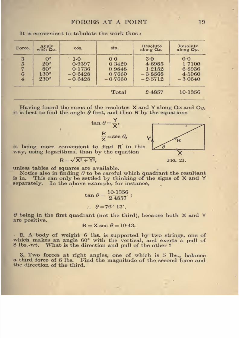
It is convenient to tabulate the work thus :
Total 2-4857
19
Angle Resolute Resolutewith O^. along Ox. along Oy.
3 0° 10 00 3-0 0-0
5 20° 0-9397 0-3420 4-6985 1-7100
7 80° 0-1736 0-9848 1-2152 6-8936
6 130° -0-6428 0-7660 - 3-8568 4-5960
4 230° -0-6428 - 0-7660 -2-5712 - 3 0640
101356
Having found the sums of the resolutes X and Y along Ox and Oy,
it is best to find the angle 6 first, and then R by the equations
R=sec^.
it being more convenient to find R in this
way, using logarithms, than by the equation
R=v/X^TY^,
unless tables of squares are available.
Notice also in finding ^ to be careful which quadrant the resultant
is in. This can only be settled by thinking of the signs of X and Y
separately. In the above example, for instance.
tan10-1356
2-4857
.-. ^=76° 13',
being in the first quadrant (not the third), because both X and Yare positive.
R = Xsec ^ = 10-43.
2. A body of weight 6 lbs. is supjwrted by two strings, one of
which makes an angle 60° with the vertical, and exerts a pull of
8 Ibs.-wt. What is the direction and pull of the other ?
3. Two forces at right angles, one of which is 6 lbs., balance
a third force of 6 lbs. Find the magnitude of the second force andthe direction of the third.
8/4/2019 Elementary Statics of 2 & Dimensions R.J.a. Barnard 1921
http://slidepdf.com/reader/full/elementary-statics-of-2-dimensions-rja-barnard-1921 32/272
20 ELEMENTARY STATICS
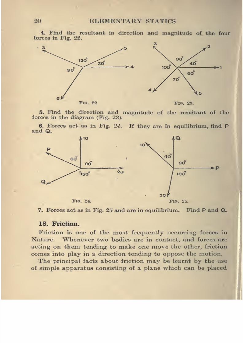
4. Find the resultant in direction and magnitude of the four
forces in Fig. 22.
>4
Fia. 22 Fig. 23.
5. Find the direction and magnitude of the resultant of the
forces in the diagram (Fig. 23).
6. Forces act as in Fig. 24. If they are in equilibrium, find Pand Q.
^P
Fio. 24. Fig. 25.
7. Forces act as in Fig. 25 and are in equilibrium. Find P and Q.
18. Friction.
Friction is one of the most frequently occurring forces in
Nature. Whenever two bodies are in contact, and forces are
acting on them tending to make one move the other, friction
comes into play in a direction tending to oppose the motion.
The principal facts about friction may be learnt by the use
of simple apparatus consisting of a plane which can be placed
^1
8/4/2019 Elementary Statics of 2 & Dimensions R.J.a. Barnard 1921
http://slidepdf.com/reader/full/elementary-statics-of-2-dimensions-rja-barnard-1921 33/272
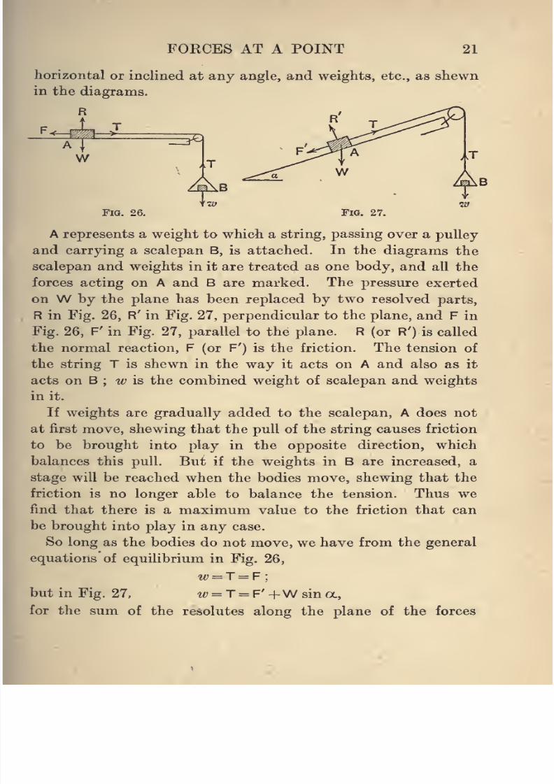
FORCES AT A POINT 21
horizontal or inclined at any angle, and weights, etc., as shewn
in the diagrams.
R
W
Fia. 26. Fig. 27.
A represents a weight to which a string, passing over a pulley
and carrying a scalepan B, is attached. In the diagrams the
scalepan and weights in it are treated as one body, and all the
forces acting on A and B are marked. The pressure exerted
on W by the plane has been replaced by two resolved parts,
R in Fig. 26, R' in Fig. 27, perpendicular to the plane, and F in
Fig. 26, F' in Fig. 27, parallel to the plane. R (or R') is called
the normal reaction, F (or F') is the friction. The tension of
the string T is shewn in the way it acts on A and also as it
acts on B; w is the combined weight of scalepan and weights
in it.
If weights are gradually added to the scalepan, A does not
at first move, shewing that the pull of the string causes friction
to be brought into play in the opposite direction, which
balances this pull. But if the weights in B are increased, a
stage will be reached when the bodies move, shewing that the
friction is no longer able to balance the tension. Thus we
find that there is a maximum value to the friction that can
be brought into play in any case.
So long as the bodies do not move, we have from the general
equations of equihbrium in Fig. 26,
w = T = F;
but in Fig. 27, w = T = F'+Wsina,
for the sum of the resolutes along the plane of the forces
8/4/2019 Elementary Statics of 2 & Dimensions R.J.a. Barnard 1921
http://slidepdf.com/reader/full/elementary-statics-of-2-dimensions-rja-barnard-1921 34/272
22 ELEMENTARY STATICS
acting on A is zero. Thus, by increasing the weight w till
the bodies just move, we can deduce the maximum friction
in either case.
Also, in Fig. 26, R =W;
but in Fig. 27, taking resolutes perpendicular to the plane,
R' =W cos oc.
If we continue the experiments, varying the weight of A by
placing other weights on top of it, we find that the maximum
friction is nearly proportional to the normal reaction, and that
the ratio maximum friction
normal reaction
is the same on the horizontal,plane or the incline, and depends
only on the nature of the surfaces in contact (including in
nature, degree of polish), and not on the area or shape of the
surfaces in contact.
We will therefore take it as a closely approximate result that
where F^a^ denotes the maximum friction and /* is a constant
for a given pair of bodies in contact.
At will be called the coefficient of friction.
The value of fx. varies greatly for different pairs of materials.
For smooth blocks of wood /z may lie between 0-25 and 0-50.
For wood on glass, betwteen 0-20 and 0-40. But there is no
limit to the values /u may assume in different cases ; it may
have any value from zero upwards.
The beginner must be careful to notice that the coefficient
of friction is the ratio of the maximum friction to the normal
component of the reaction, not of the maximum friction to the
weight. The normal reaction may be quite different from the
weight. Also it must always be remembered that when a
certain value is given for the coefficient of friction, while the
friction cannot be greater than /x times the normal reaction,
J
I
8/4/2019 Elementary Statics of 2 & Dimensions R.J.a. Barnard 1921
http://slidepdf.com/reader/full/elementary-statics-of-2-dimensions-rja-barnard-1921 35/272
FORCES AT A POINT 23
it may according to circumstances be anything less than that
maximum.
When the surfaces are such that no tfiction can act betweenthem, or yU = 0, they are said to be perfectly smooth. This
never occurs in nature. However, in many examples bodies
will be spoken of as smooth, meaning that no friction is supposed
to act. It does not necessarily imply that the results would
be affected if friction could act. For example, if we are asked
what force acting in a certain direction is required to keep a
given body from sliding down a given smooth inclined plane,
we know that such a plane does not exist, but we also know
that if we calculate the force on the supposition that there
is no friction, then if that force is applied the body will rest
on the plane without any friction being brought into play.
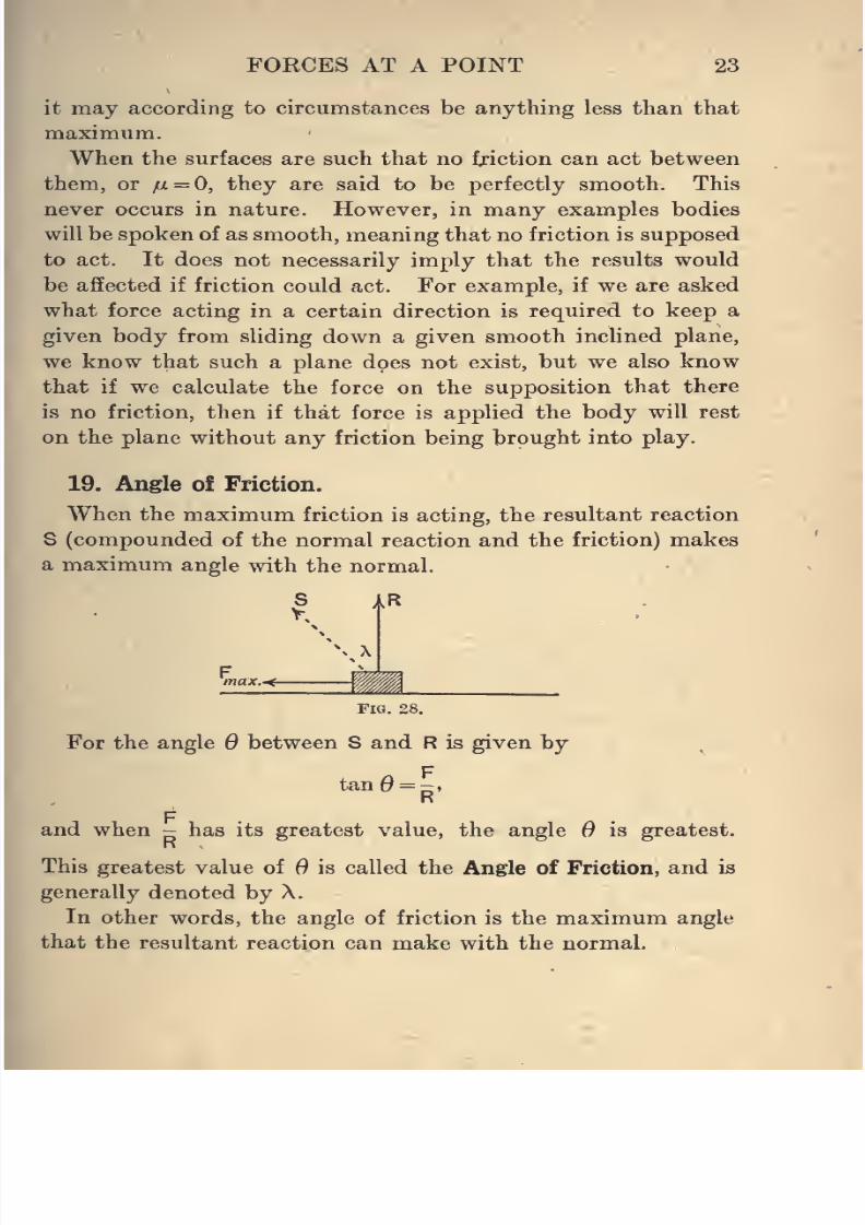
19. Angle of Friction.
When the maximum friction is acting, the resultant reaction
S (compounded of the normal reaction and the friction) makes
a maximum angle with the normal.
max.<-
FlG. 28.
For the angle Q between S and R is given by
tan0 = -,R
Fand when - has its greatest value, the angle is greatest.
R
This greatest value of B is called the Angle of Friction, and is
generally denoted by A.
In other words, the angle of friction is the maximum angle
that the resultant reaction can make with the normal.
8/4/2019 Elementary Statics of 2 & Dimensions R.J.a. Barnard 1921
http://slidepdf.com/reader/full/elementary-statics-of-2-dimensions-rja-barnard-1921 36/272
24 ELEMENTARY STATICS
Also we have tanX =
giving the relation between X and //.
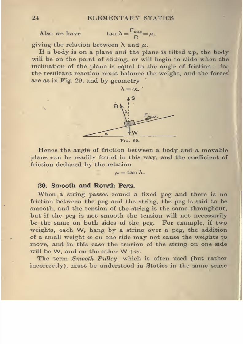
If a body is on a plane and the plane is tilted up, the body
will be on the point of sliding, or will begin to slide when the
inclination of the plane is equal to the angle of friction ; for
the resultant reaction must balance the weight, and the forces
are as in Fig. 29, and by geometry
X = a.
Fig. 2
^Hence the angle of friction between a body and a movable
plane can be readily found in this way, and the coefficient of
friction deduced by the relation
jj. — tan X.
20. Smooth and Rough Pegs.
When a string passes round a fixed peg and there is no
friction between the peg and the string, the peg is said to be
smooth, and the tension of the string is the same throughout,
but if the peg is not smooth the tension will not necessarily
be the same on both sides of the peg. For example, if two
weights, each W, hang by a string over a peg, the addition
of a small weight w on one side may not cause the weights to
move, and in this case the tension of the string on one side
will be W, and on the other W +w.
The term Smooth Pulley, which is often used (but rather
incorrectly), must be understood in Statics in the same sense
I
8/4/2019 Elementary Statics of 2 & Dimensions R.J.a. Barnard 1921
http://slidepdf.com/reader/full/elementary-statics-of-2-dimensions-rja-barnard-1921 37/272
FORCES AT A POINT 25
as a smooth peg, namely a body whicli will let a string pass
round it without any friction being exerted, in which case,
however, the pulley would not be turned round by a pull
in the string.
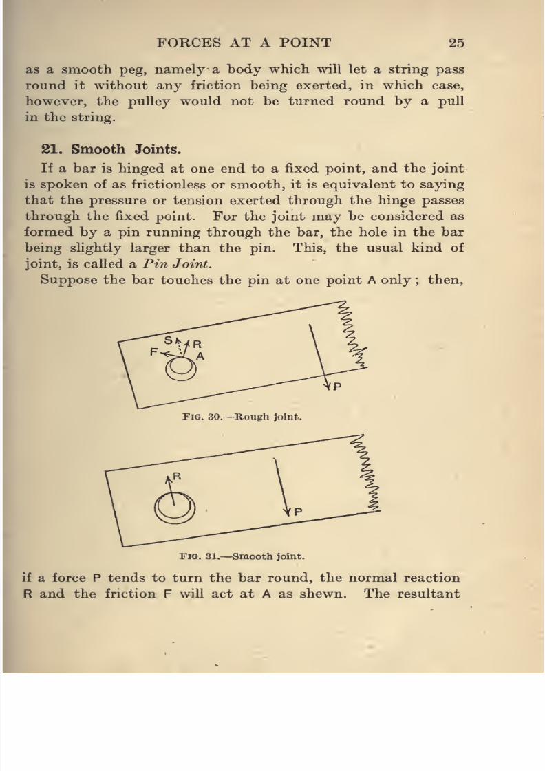
31. Smooth Joints.
If a bar is hinged at one end to a fixed point, and the joint
is spoken of as frictionless or smooth, it is equivalent to saying
that the pressure or tension exerted through the hinge passes
through the fixed point. For the joint may be considered as
formed by a pin running through the bar, the hole in the bar
being slightly larger than the pin. This, the usual kind of
joint, is called a Pin Joint.
Suppose the bar touches the pin at one point A only ; then,
Fig. 30.—Rough joint.
Fig. 31.—Smooth joint.
if a force P tends to turn the bar round, the normal reaction
R and the friction F will act at A as shewn. The resultant
8/4/2019 Elementary Statics of 2 & Dimensions R.J.a. Barnard 1921
http://slidepdf.com/reader/full/elementary-statics-of-2-dimensions-rja-barnard-1921 38/272
26 ELEMENTARY STATICS
reaction will not therefore act through the centre of the pin,
but if there were no friction it would do so.
The difference between the cases when there is friction at a
joint and when there is not, will be seen better after deaUng
with moments of forces in Chapter V.
22. Methods of attacking Problems.
Summing up the work of the chapter, we find that when
there are only coplanar concurrent forces acting, there are
two ways of dealing with cases where there are only three
forces, namely by
(i) the triangle of forces, or its alternative form, Lami's
theorem, '
(ii) resolving in two directions.
For more than three forces the method of resolving is usually
the only one available, but occasionally two of the forces maybe conveniently reduced to one, and thus a question with four
forces reduced to one with three.
The work of the chapter may be illustrated by a number of
examples.
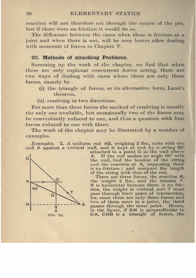
Examples. 1. A uniform rod AB, weighing 2 lbs., rests with one
end A against a vertical wall, and is kept at rest by a string BC
attached to a point C in the wall aboveA. If the rod makes an angle 60° with
the wall, find the tension of the string
and the reaction at A, supposing there
is no friction ; and compare the length
of the string with that of the rod.
There are three forces, the reaction R,
the weight 2 lbs., and the tension T.
R is horizontal because there is no fric-
tion,the weight
is vertical, andTmust
pass through their point of intersection,
for, since there are only three forces and
two of them meet in a point, the third
passes through the same point. Hence,
in the figure, if BN is perpendicular to
CA, CNB is a triangle of forces, the
I
8/4/2019 Elementary Statics of 2 & Dimensions R.J.a. Barnard 1921
http://slidepdf.com/reader/full/elementary-statics-of-2-dimensions-rja-barnard-1921 39/272
FORCES AT A POINT 27
Let
weight being parallel to CN, R parallel to NB, and T along BC, and
we have by geometry,
since G is the middle point of AB,
.'. O is the middle point of BC ;
.'. A is the middle point of CN.
AB =2a
:. AN=a,
CN =2a,
NB=av/3,
CB = VCN2 + NB2=aV7.
T ^ R ^ 2
CB~NB~CNT _ R 2
.
:. 7 = ^7 =2-65 lbs.-wt.,
R=v^3 = l-73 lb8.-wt.,
CBv^BA~^3
Hence
:nA2-33 = 1-53.
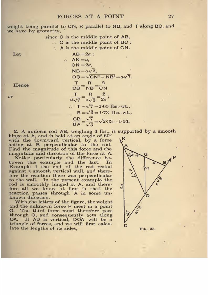
S. A uniform rod AB, weighing 4 lbs., is supported by a smooth
hinge at A, and is held at an angle of 60°
with the dowTiward vertical, by a force
acting at B perpendicular to the rod.
Find the magnitude of this force and the
magnitude and direction of the force at A.
Notice particularly the difference be-
tween this example and the last. InExample 1 the end of the rod rested
against a smooth vertical wall, and there-
fore the reaction there was perpendicular
to the wall. In the present example the
rod is smoothly hinged at A, and there-
fore all we know at first is that the
reaction passes through A in some un-
known direction.
With the letters of the figure, the weightand the unknown force P meet in a point
O. The third force must therefore pass
through O, and consequently acts along
OA. If AD is vertical, DOA will be a
triangle of forces, and we will first calcu-
late the lengths of its sides. Fig. 33.
8/4/2019 Elementary Statics of 2 & Dimensions R.J.a. Barnard 1921
http://slidepdf.com/reader/full/elementary-statics-of-2-dimensions-rja-barnard-1921 40/272
28 ELEMENTARY STATICS
Let AB=2o:
.-. DB=2aN/3;
.-. D0=a\/3
also OB =aV3
.-. OA=a\/7:
• -^ =_^=i •
o-s/S ov/7 4a'
.-. P = v'3 = l-731b8.-wt.,
R = V7=2-65 „
also the angle R makes with the rod is given by
tan OAB='^ =0-866;
/. OAB=40°54'.
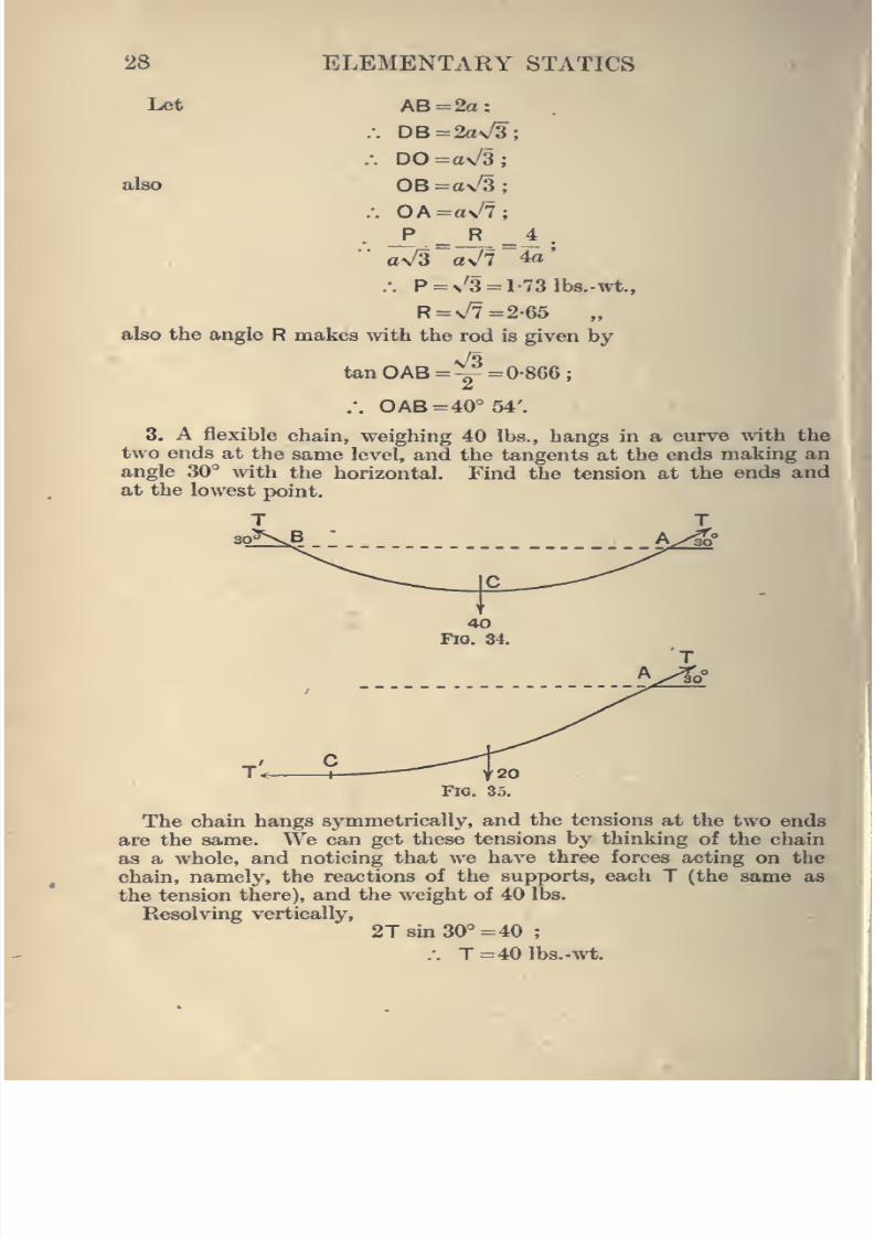
3. A flexible chain, weighing 40 lbs., hangs in a curve with the
two ends at the same level, and the tangents at the ends making an
angle 30° with the horizontal. Find the tension at the ends andat the lowest point.
The chain hangs symmetrically, and the tensions at the two ends
are the same. We can get these tensions by thinking of the chain
as a whole, and noticing that we have three forces acting on ther '.
chain, namely, the reactions of the supports, each T (the same as
the tension there), and the weight of 40 lbs.
Resolving vertically,
2T8m30°=40 ;
.-. T=401bs.-wt.
8/4/2019 Elementary Statics of 2 & Dimensions R.J.a. Barnard 1921
http://slidepdf.com/reader/full/elementary-statics-of-2-dimensions-rja-barnard-1921 41/272
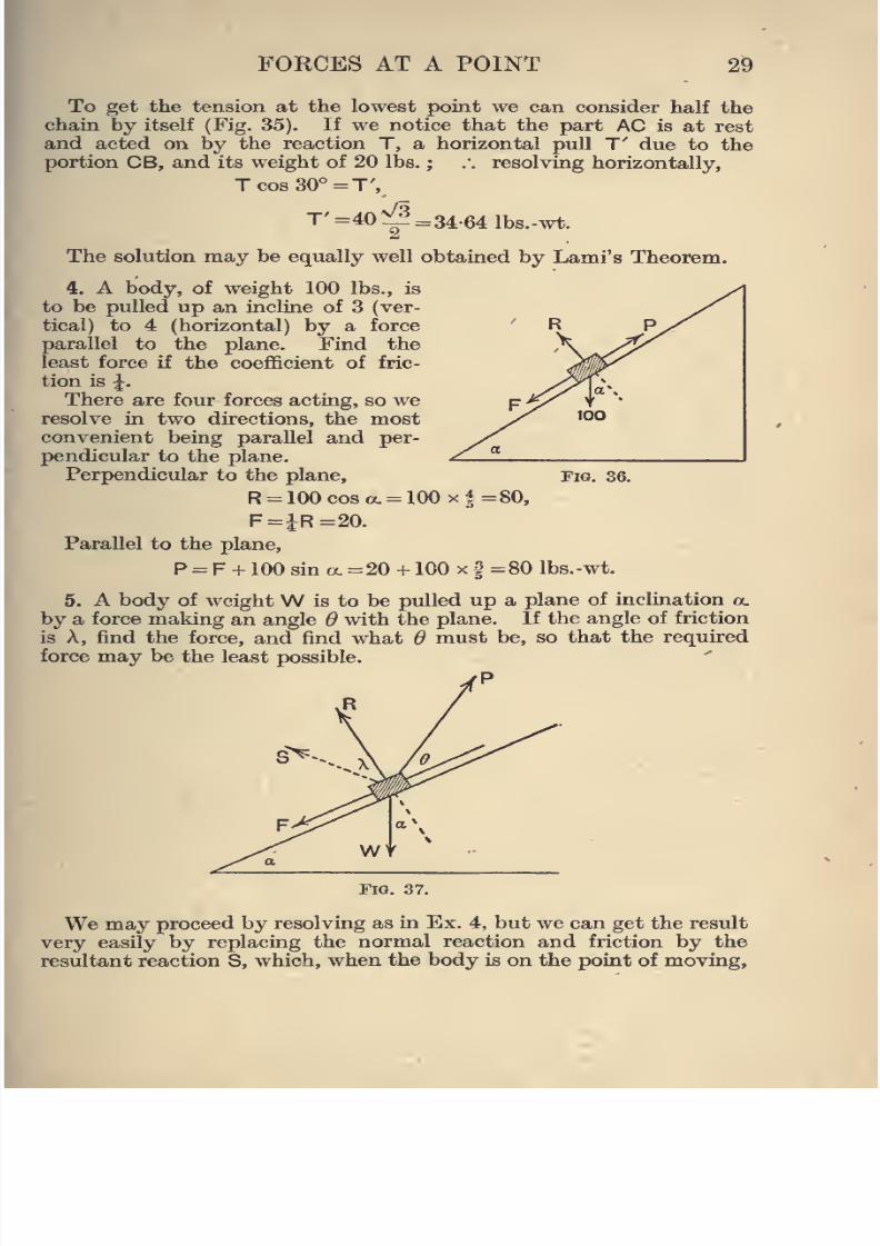
FORCES AT A POINT 29
To get the tension at the lowest point we can consider half the
chain by itself (Fig. 35). If we notice that the part AC is at rest
and acted on by the reaction T, a horizontal pull T' due to the
portion CB, and its weightof
20 lbs.; .•.
resolving horizontally,Tcos30°=T',
T' =40^ =34-64 lbs.-wt.
The solution may be equally well obtained by Lami's Theorem.
4. A body, of weight 100 lbs., is
to be pulled up an incline of 3 (ver-
tical) to 4 (horizontal) by a force
parallel to the plane. Find the
least force if the coefficient of fric-
tion is J.
There are four forces acting, so weresolve in two directions, the most
convenient being parallel and per-
pendicular to the plane.
Perpendicular to the plane,
R = 100cosa. = 100x4=80,
F=JR=20.
Parallel to the plane,
P = F + 100 sin a. =20 + 100 x f=80 Ibs.-wt.
5. A body of weightW is to be pulled up a plane of inclination a.
by a force making an angle 6 with the plane. If the angle of friction
is A, find the force, and find what 6 must be, so that the required
force may be the least possible.
rP
Fig. 36.
Fig. 37.
We may proceed by resolving as in Ex. 4, but we can get the result
very easily by replacing the normal reaction and friction by the
resultant reaction S, which, when the body is on the point of moving,
8/4/2019 Elementary Statics of 2 & Dimensions R.J.a. Barnard 1921
http://slidepdf.com/reader/full/elementary-statics-of-2-dimensions-rja-barnard-1921 42/272
30 ELEMENTARY STATICS
acts an angle A with the normal. We then have three forces only,
and can use Lami's Theorem. We have then
P S Wsin (180 -a. -A) sin(90+a+ ^) sin (90+ A- ^)'
P ^ ^'
^ W8in(a.+ A) cos(a.+ ^)~co8(^- A)
p^^8in(oL+A)
C08(^-A)*
Hence, for different values of 0, P is least when cos (^ - A) is greatest,
that is, when ^ = A,
or
andP is at right angles to S,
P„i.=W8in(a. + A).
23. Particles connected by a String.
When two particles are connected by a string it is generally
necessary to deal with each separately, noticing that the
string pulls each body with the same force. The student
should therefore mark the tension as it acts on each body,
and form the equations for each body by Lami's Theorem
or otherwise.
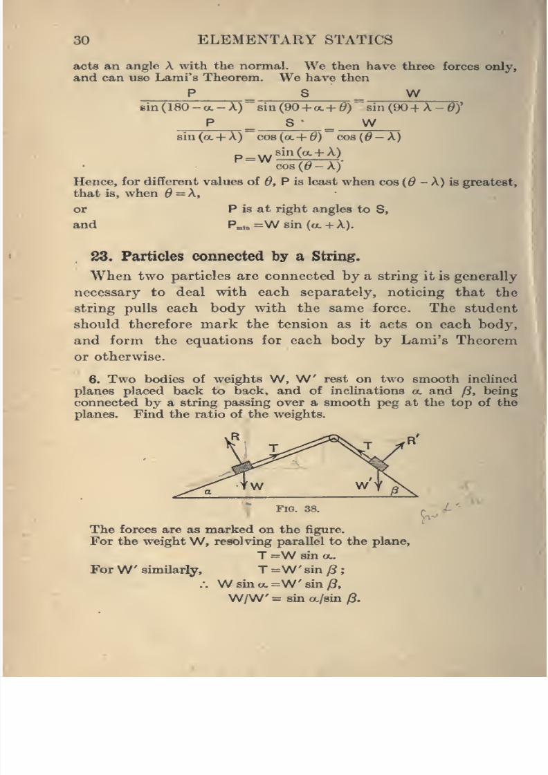
6. Two bodies of weights W, W rest on two smooth inclined
planes placed back to bsick, and of inclinations a. and /3, being
connected by a string passing over a smooth peg at the top of the
planes. Find the ratio of the weights.
Fig. 38.
The forces are as marked on the figure.For the weight W, resolving parallel to the plane,
T=W sin OL.
ForW similarly, T =W sin (i
:. W sin a. =W' sin (S,
W/W'= sin a/sin /8.
8/4/2019 Elementary Statics of 2 & Dimensions R.J.a. Barnard 1921
http://slidepdf.com/reader/full/elementary-statics-of-2-dimensions-rja-barnard-1921 43/272
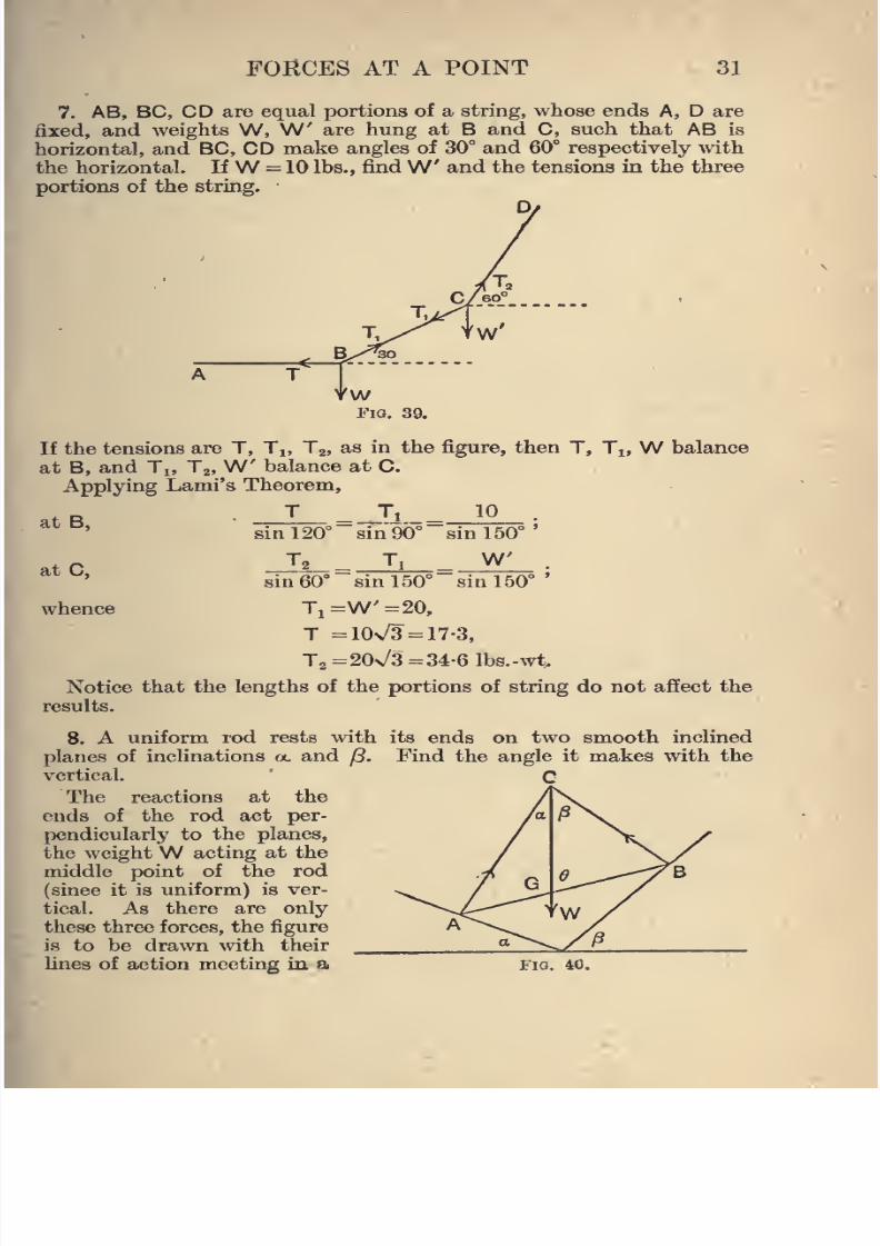
FORCES AT A POINT 31
7. AB, BC, CD are equal portions of a string, whose ends A, D are
fixed, and weights W, W are hung at B and C, such that AB is
horizontal, and BC, CD make angles of 30° and 60° respectively with
the horizontal. IfW = 10 lbs., find
W and the tensions in the threeportions of the string.
D/
If the tensions are T, Tj, Tg, as in the figure, then T, Ti, W balance
at B, and Tj, Tj,W balance at 0.
Applying Lami's Theorem,
T __Ti_ 10
"sin 90°'t B,
at C,
whence
sin 120
sin 60'
T,
sin 150°'
W"sin 150°in 150°
Ti=W'-20,
T =10n/3 = 17-3,
T„=20\/3=34-61b8.-wt
Notice that the lengths of the portions of string do not affect the
results.
8. A uniform rod rests with its ends on two smooth Inclined
planes of inclinations a. and j3. Find the angle it makes with the
vertical.
The reactions at the
ends of the rod act per-
pendicularly to the planes,
the weightW acting at themiddle point of the rod
(since it is uniform) is ver-
tical. As there are only
these three forces, the figure
is to be drawn with their
lines of action meeting in a Fia. 40.
8/4/2019 Elementary Statics of 2 & Dimensions R.J.a. Barnard 1921
http://slidepdf.com/reader/full/elementary-statics-of-2-dimensions-rja-barnard-1921 44/272
32 ELEMENTARY STATICS
point. If ^ is the angle the rod makes with the vertical, 6 can be
found as follows
From the triangle AGC,
sin GAG/ sinACQ =CG/AG,sin (6 -a.)l sin a. =CG/G A.
Similarly, from the triangle BCG,
sin((9+/i)/8in/?=CG/GB,
sin(^ -0L)/sina.=sin(^ + ^)/sin/8,
sin cot a. -cos^=sin^cot/3+cos^,
2 cos 6=sm0 (cot a. - cot j8),
or 2cot ^=cota. -cotjS.
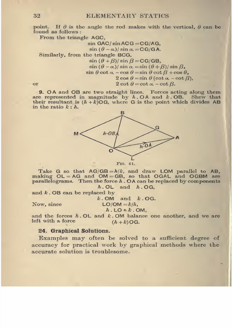
9. OA and OB are two straight lines. Forces acting along them
are represented in magnitude by h.OA and k.OB. Shew that
their resultant is {h+k)OG, where G is the point which divides ABin the ratio k : h.
Take G so that AG/GB=A/A:, and draw L.OM parallel to AB,
making OL = AG and OM=GB, so that OGAL and OGBM are
parallelograms. Then the force h.OA can be replaced by components
h.OL and A.OG,
and A; . OB can be replaced by
k . OM and k . OG.
Now, since LO/OM = kjh,
h.LO*-k.OM,
and the forces h.OL and k.OM balance one another, and we arej
left with a force /^ + i) OG.
24. Graphical Solutions.
Examples may often be solved to a sufficient degree of
accuracy for practical work by graphical methods where the
accurate solution is troublesome.
8/4/2019 Elementary Statics of 2 & Dimensions R.J.a. Barnard 1921
http://slidepdf.com/reader/full/elementary-statics-of-2-dimensions-rja-barnard-1921 45/272
FORCES AT A POINT 33
For example, if we wanted an approximate solution of No. 1,
Art. 22, we have only to draw the figure on a fairly large scale
and measure off the sides of the triangle AOC.
Thus, draw first the vertical AN, and AB at an angle 60°
with it. Make AN and AC each = 2 inches; draw NB hori-
zontal, and finish off the figure as in the diagram. Then the
sides AO, OC will represent the reaction and tension on the
scale of 1 Ib.-wt. to the inch and the angle ACB can be measured
off by a protractor.
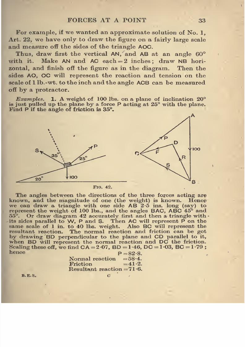
Examples. 1. A weight of 100 lbs. on a plane of inclination 20''
is just pulled up the plane by a force P acting at 25° with the plane.
Find P if the angle of friction is 35°.
A
100
Fig. 42.
The angles between the directions of the three forces acting are
known, and the magnitude of one (the weight) is known. Hencewe can draw a triangle with one side AB 2-5 ins. long (say) to
represent the weight of 100 lbs., and the angles BAG, ABC 45° and55°. Or draw diagram 42 accurately first and then a triangle with •
-its sides parallel to W, P and S. Then AC will represent P on the
same scale of 1 in. to 40 lbs. weight. Also BC will represent the
resultant reaction. The normal reaction and friction can be got
by drawing BD perpendicular to the plane and CD parallel toit,
when BD will represent the normal reaction and DC the friction.
Scaling these off, we find CA =207, BD =1-46, DC = 1-03, BC = 1-79;
hence P=82-8.
Normal reaction =58-4.
Friction =41-2.
Resultant reaction =71-6.
B.E.S. c
8/4/2019 Elementary Statics of 2 & Dimensions R.J.a. Barnard 1921
http://slidepdf.com/reader/full/elementary-statics-of-2-dimensions-rja-barnard-1921 46/272
34 ELEMENTAKY STATICS
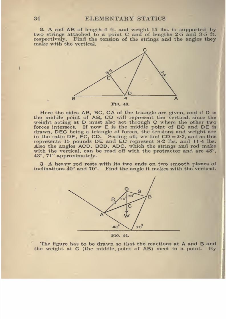
2. A rod AB of length 4 ft. and weight 15 lbs. is supported by
two strings attached to a point C and of lengths 2-5 and 3-5 ft.
respectively. Find the tension of the strings and the angles they
make with the vertical.
II
Here the sides AB, BC, CA of the triangle are given, and if D is
the middle point of AB, CD will represent the vertical, since the
weight acting at D must also act through C where the other two
forces intersect. If now E is the middle point of BC and DE is
drawn, DEC being a triangle of forces, the ten.sions and weight are
in the ratio DE, EC; CD. Scaling off, we find CD =2-3, and as this
represents 15 pounds DE and EC represent 8-2 lbs. and 11-4 lbs.
Also the angles ACD, BCD, ADC, which the strings and rod makewith the vertical, can be read off with the protractor and are 48°,
43°, 71° approximately.
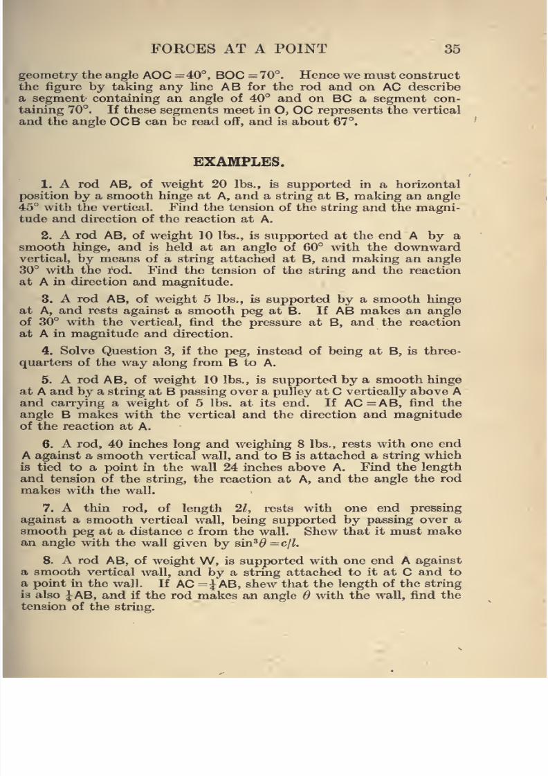
3. A heavy rod rests with its two ends on two smooth planes of
inclinations 40° and 70°. Find the angle it makes with the vertical.
Fig. 44.
The figure has to be drawn so that the reactions at A and B and
the weight at C (the middle point of AB) meet in a point. By
8/4/2019 Elementary Statics of 2 & Dimensions R.J.a. Barnard 1921
http://slidepdf.com/reader/full/elementary-statics-of-2-dimensions-rja-barnard-1921 47/272
FORCES AT A POINT 35
geometry the angle AOC =40°, BOC =70°. Hence we must construct
the figure by taking any fine AB for the rod and on AC describe
a segment containing an angle of 40° and on BC a segment con-
taining 70°. If these segments meet in O, OC represents the vertical
and the angle OCB can be read off, and is about 67°.
EXAMPLES.
1. A rod AB, of weight 20 lbs., is supported in a horizontal
position by a smooth hinge at A, and a string at B, making an angle
45° with the vertical.
Findthe tension of
thestring
and the magni-tude and direction of the reaction at A.
2. A rod AB, of weight 10 lbs., is supported at the end A by a
smooth hinge, and is held at an angle of 60° with the downwardvertical, by means of a string attached at B, and making an angle
30° with the rod. Find the tension of the string and the reaction
at A in direction and magnitude.
3. A rod AB, of weight 5 lbs., is supported by a smooth hinge
at A, and rests against a smooth peg at B. If AB makes an angle
of 30° with the vertical, find the pressure at B, and the reaction
at A in magnitude and direction.
4. Solve Question 3, if the peg, instead of being at B, is three-
quarters of the way along from B to A.
5. A rod AB, of weight 10 lbs., is supported by a smooth hinge
at A and bj' a string at B passing over a pulley at C vertically above A
and carrying a weight of 5 lbs. at its end. If AC=AB, find the
angle B makes with the vertical and the direction and magnitude
of the reaction at A.
6. A rod, 40 inches long and weighing 8 lbs., rests with one end
A against a smooth vertical wall, and to B is attached a string which
is tied to a point in the wall 24 inches above A. Find the length
and tension of the string, the reaction at A, and the angle the rod
makes with the wall.
7. A thin rod, of length 21, rests with one end pressing
against a smooth vertical wall, being supported by passing over a
smooth peg at a distance c from the wall. Shew that it must makean angle with the wall given by sin*^ =c/i.
8. A rod AB, of weight W, is supported with one end A against
a smooth vertical wall, and by a string attached to it at C and to
a point in the wall. If AC =i AB, shew that the length of the string
is also JAB, and if the rod makes an angle 6 with the wall, find the
tension of the string.
8/4/2019 Elementary Statics of 2 & Dimensions R.J.a. Barnard 1921
http://slidepdf.com/reader/full/elementary-statics-of-2-dimensions-rja-barnard-1921 48/272
36 ELEMENTARY STATICS
9. A sphere, of weightW and radius r, rests on a smooth plane
of inclination a., being kept at rest by a horizontal string attached
to the sphere and to a point in the plane. Find the length and
tension of the string, and the reaction at the point of contact.
10. A sphere, of weight 3 lbs., rests in the angle between twoplanes, one of which is vertical and the other inclined at an angle
of 30° to the vertical. Find the pressures on the planes.
11. A sphere, of weight W, rests on two planes of inclinations
OL, p. Find the pressures on the planes.
12. Two spheres, of weights \N,\N', rest one on each of two planes
placed back to back of inclinations a., a.', being connected by a
string which runs horizontally from one to the other. Shew that
W tan OL =W tan a.'.
13. A rod, of weight 6 lbs., rests with its ends on two smooth
planes of inclinations 30° and 60°. Find the angle the rod makes
with the vertical, and find the pressures on the planes.
14. A rod rests with its ends on two smooth planes of inclinations
40° and 70°. Find the angle that it makes \\ith the vertical.
15. ABCDis
astring,
and equal weightsWare
attachedat
Band
C, and BC remains horizontal, while AB, CD make angles of 60°
with the horizontal. Find the tensions.
16. A small ring, of weight W, can slide on a smooth vertical
circle, and is attached to the highest point by a string which subtends
an angle 2«. at the centre. Find the tension of the string.
17. Whet is the least force parallel to the incline which will
pull a body of weight 100 lbs. up an incline of 30° if the coefficient
of friction is 0-2 ?
Find also the least force that will prevent it from sliding down.
18. A plane slopes at 5 (vertical) to 12 (horizontal). Find the
greatest and least forces parallel to the plane which can act on a
body of weight 26 lbs. on the plane without its moving, if the
efficient of friction is 0-25.
19. Find the least force (in any direction) necessary to move a
body of weight W along a horizontal plane if the coefficient of
friction is 0-75.
20. Find the least force required to move a body of weight 20 11
along a horizontal plane if the coefficient of friction is 1 '0.
21. Find the least horizontal force required to move a body
weight 50 lbs. up an incline of 30° if the coefficient of friction is 0-5.
22. Find the least horizontal force required to move a body of
weight 120 lbs. up an incline of 25° if the coefficient of friction is 0-3.
I
e a
, of
11
8/4/2019 Elementary Statics of 2 & Dimensions R.J.a. Barnard 1921
http://slidepdf.com/reader/full/elementary-statics-of-2-dimensions-rja-barnard-1921 49/272
FORCES AT A POINT 37
23. Shew that the least force necessary to stop a body from
running down a plane of inclination a., when the angle of friction
is A, must be applied at an angle A with the plane (A<ol).
24. What force, applied at an angle of 15° to the plane, will be
required to drag a body of weight 140 lbs. up an incline of 35° if
the coefficient of friction is 0-5 ?
25. A wheel, of radius r and weight W, is to be dragged over a
rectangular block of stone of height ^ ( < r), by means of a horizontal
force applied at its centre. Find the magnitude of the force whenthe lowest point of the wheel is at a height k above the ground, and
find the smallest force P required.
Examine the case when r =30 inches, A = 18 inches,
W=50 lbs.
26. Equal particles are hung from a series of points on a weightless
string. Shew that if di, 6^, ... are the angles the successive portions
make with the horizontal, tan 6^, tan 6^, ... are in A.P., and that
the horizontal components of the tensions are the same.
27. If in Question 26 the points of attachment of the weights are
such that the projections on the horizontal of the separate portions
of the string are each equal to a, and the first portion starting
from the lower end is horizontal with a tension Tq in it, and the
suspended weights are each W, prove that the x and y coordinates of^(^ \\ XA/flt
the n"* angle measured from the lower end are na and -~ - ^j;— ,
and hence that the angles lie on a parabola.
28. A block, of weight W, rests on a rough horizontal plane. Apiston presses down upon it with force P. If the coefficient of friction
is /x at each contact, what is the least horizontal force required
to draw out the block ?
29. AB is a weightless rod carrying a weight W at a point which
divides the rod in the ratio a: b. It is supported by strings at the
ends, making angles a. and /? with the vertical. Shew that the rod
makes an angle 6 with the vertical given by
{a + b) cot = b cot f3-a cot a.,
and find the tensions of the strings.
30. A weight w rests on a rough horizontal table, the coefficient
of friction being fi. To it are attached two springs which pass over
pulleys and carry weights W at the end of each. The strings each
make an angle a. with the horizontal. If
anextra weight
Wis
added to one of these, shew that in limiting equilibrium
W =fi{w -2W sin a.)/(cos a. +/x sin a.).
31. A ring, of weight w, slides on a smooth vertical circular wire
of radius a, being attached to the extremity of the horizontal diameter
by a string of length a/2. Shew that the tension is approximately
0-9w, and find the pressure.
8/4/2019 Elementary Statics of 2 & Dimensions R.J.a. Barnard 1921
http://slidepdf.com/reader/full/elementary-statics-of-2-dimensions-rja-barnard-1921 50/272
38 ELEMENTARY STATICS
32. A weight of 100 lbs. is supported on a rough plane of inclina-
tion 30°, by a rope at an inclination 45° with the horizontal. If
the coefficient of friction is 0-25, find the greatest and least tensions
of the rope consistent with equilibrium.
33. ABC is a triangle, and D is a point in BC. Forces P, Q, along
AB, AC have a resultant R along AD. Prove that
P/R=CD.AB/BC.AD.
34. A ring C slides on a string whose ends are 2 ft. apart, ABmaking an angle 30° with the horizontal. Shew that in the position
of equilibrium the two portions of the string make equal angles with
the vertical, and if the length of the string is 2 \/3 ft., shew that
these angles are 30°.
Solve the follatving questions graphically :
35. A rod AB, of weight 20 lbs., is smoothly hinged at A, and is
held at an angle 50° T^ith the upward vertical by a string attached
to B and to a point above A and making an angle 20° with the
vertical. Find the tension of the string and the reaction at A.
36. A rod AB, of length 2 ft. and weight 10 lbs., is supported by
a smooth hinge at A and by a string attached at B which passes
over a smooth pulley at C verticall}' above A, and supports a weight
of 5 lbs. at its end. If AC is 4 ft., find the angle the rod makes with
the vertical and the magnitude and direction of the reaction at A.
37. AB is a smooth rod fixed at an angle 40° with the horizontal.
A small ring of weight 15 oz. can slide on AB and is attached by a
string 3-5 feet long to a point vertically above A. If CA=4 ft.
find the tension of the string and pressure of the rod.
38. A sphere, of weight 15 lbs., is kept at rest on a plane of inclina-
tion 18° by a horizontal string attached to its highest point. Find
the tension of the string.
39. A rod, of weight 3 lbs. and length 2-3 ft., is hinged at one
end to the lowest point of a fixed vertical circle of radius 2 ft., and
the other end rests on the inside of the circle. Find the reactions
at each end.
40. A weight C, of 100 lbs., is hung by two wires attached to points
A and B 6 ft. apart, B being 2 ft. above A. If the lengths of thewires are 4 and 5 ft. respectively, find their tensions.
41. A ring C, of weight 2 lbs., can slide on a string 5 ft. long, whose!
ends A and B are 4 ft. apart, and the end B is 1 ft. above A. Find
the tension of the string and the lengths of AC, CB in the position
of equilibrium.
I
8/4/2019 Elementary Statics of 2 & Dimensions R.J.a. Barnard 1921
http://slidepdf.com/reader/full/elementary-statics-of-2-dimensions-rja-barnard-1921 51/272
CHAPTER III.
PARALLEL FORCES.
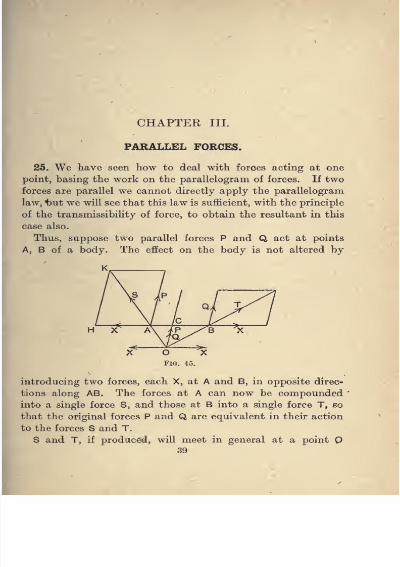
25. We have seen how to deal with forces acting at one
point, basing the work on the parallelogram of forces. If two
forces are parallel we cannot directly apply the parallelogram
law, t)ut we will see that this law is sufficient, with the principle
of the transmissibility of force, to obtain the resultant in this
case also.
Thus, suppose two parallel forces P and Q act at points
A, B of a body. The effect on the body is not altered by
H X
introducing two forces, each X, at A and B, in opposite direc-
tions along AB. The forces at A can now be compounded
into a single force S, and those at B into a single force T, so
that the original forces P and Q are equivalent in their action
to the forces S and T.
S and T, if produced, will meet in general at a point
39
8/4/2019 Elementary Statics of 2 & Dimensions R.J.a. Barnard 1921
http://slidepdf.com/reader/full/elementary-statics-of-2-dimensions-rja-barnard-1921 52/272
40 ELEMENTARY STATICS
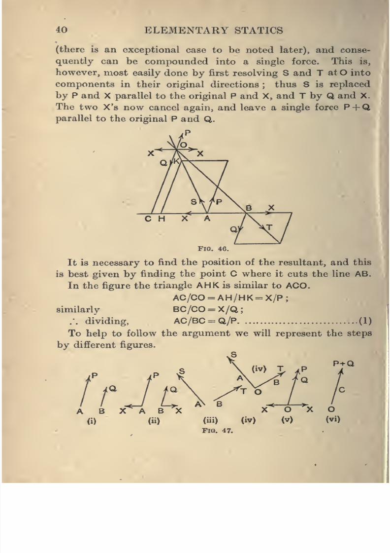
(there is an exceptional case to be noted later), and conse-
quently can be compounded into a single force. This is,
however, most easily done by first resolving S and T at O into
components in their original directions ; thus S is replaced
by P and X parallel to the original P and X, and T by Q and X.
The two X's now cancel again, and leave a single force P + Qparallel to the original P and Q.
jP
/O
^FlO. 46.
It is necessary to find the position of the resultant, and this
is best given by finding the point C where it cuts the line AB.
In the figure the triangle AHK is similar to AGO.
AC/CO = AH/HK = X/P;
similarly BC/CO = X/Q
.'. dividing, AC/BC = Q/P (1)
To help to follow the argument we will represent the steps
by different figures.
AN BA B X^ B X X O X O
(i) (ii) (iii) (iv) (v) (vi)
Fia. 47.
8/4/2019 Elementary Statics of 2 & Dimensions R.J.a. Barnard 1921
http://slidepdf.com/reader/full/elementary-statics-of-2-dimensions-rja-barnard-1921 53/272
PARALLEL FORCES 41
The beginner should follow these figures, and notice carefully
that the forces in the first are exactly equivalent to those in
the next, and so on.
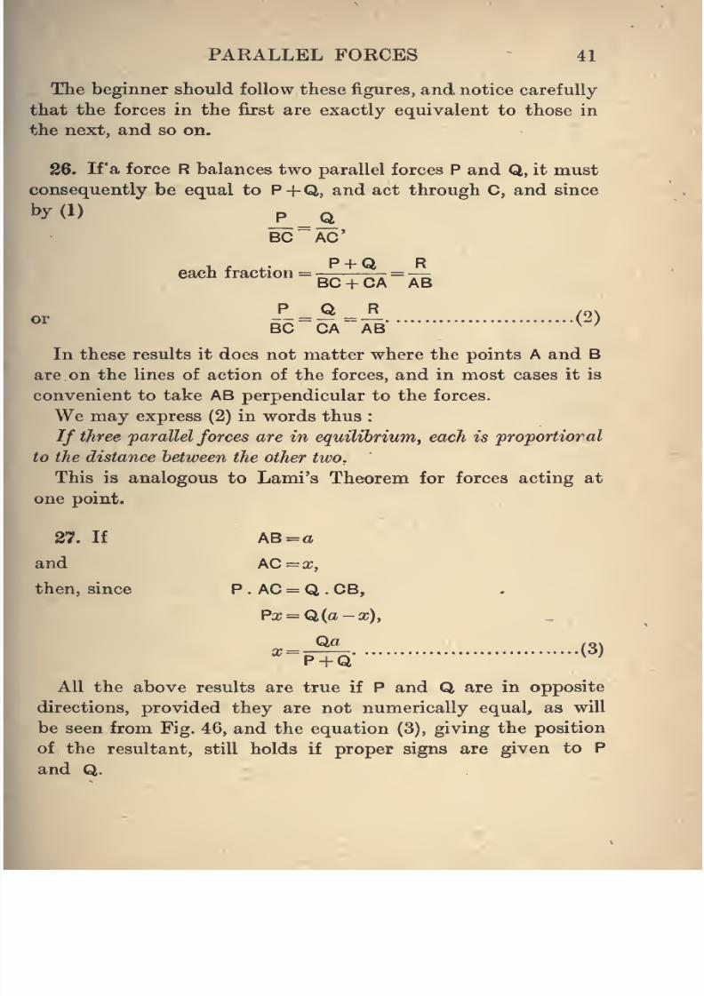
26. If'a force R balances two parallel forces P and Q, it must
consequently be equal to P + Q, and act through C, and since
by(l)p
=AC'
ion =
P +QBC + CA
R
"AB
P Q R~CA " AB"CC= ?A = A^
<^>
In these results it does not matter where the points A and B
are on the lines of action of the forces, and in most cases it is
convenient to take AB perpendicular to the forces.
We may express (2) in words thus :
If three parallel forces are in equilibrium, each is proportioral
to the distance between the other two.
This is analogous to Lami's Theorem for forces acting at
one point.
27. If AB = a
and AC = x,
then, since P . AC = Q . CB,
Pa;=Q(a-x),
Qa /q\x = -— \o)
P + Q
All the above results are true if P and Q are in opposite
directions, provided they are not numerically equal, as will
be seen from Fig. 46, and the equation (3), giving the position
of the resultant, still holds if proper signs are given to P
and Q.
8/4/2019 Elementary Statics of 2 & Dimensions R.J.a. Barnard 1921
http://slidepdf.com/reader/full/elementary-statics-of-2-dimensions-rja-barnard-1921 54/272
8/4/2019 Elementary Statics of 2 & Dimensions R.J.a. Barnard 1921
http://slidepdf.com/reader/full/elementary-statics-of-2-dimensions-rja-barnard-1921 55/272
PARALLEL FORCES 43
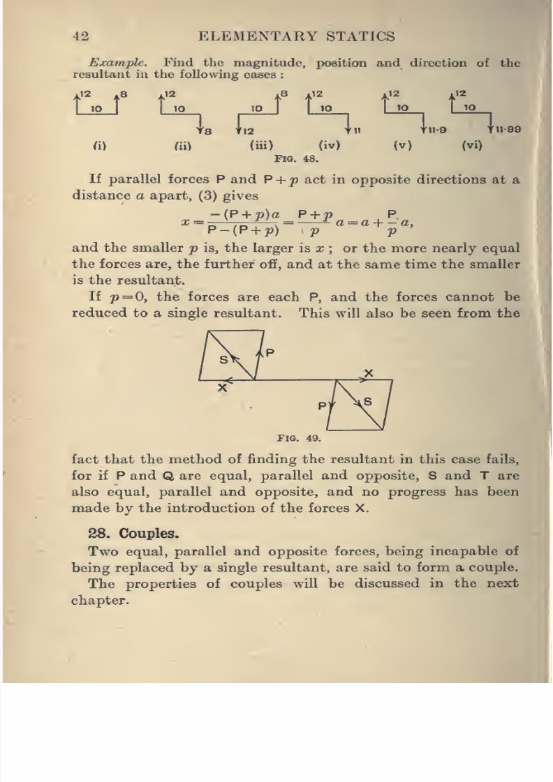
Examples. 1. Find the magnitude and position of the resultant
of the following pairs of parallel forces in the same direction
(i) 10 lbs. and 6 lbs., 8 inches apart,
(ii) 8 lbs. and 4 lbs., 20 inches apart,(iii) 5 lbs. and 4 lbs., 100 inches apart.
2. Find the resultants of the pairs of forces as in Question (1),
but with the forces acting in opposite directions.
3. A weightless rod, of length 15 inches, caixies a weight of 10 lbs.,
4 inches from one end, and is supported in a horizontal position byspring balances attached to the ends of the rod. What will the
readings of the spring balances be ?
4. A beam AB, 16 feet long and weighing 120 lbs., rests on twosupports, one 1 foot from A, and the other 3 feet from B. Find the
pressure on each support.
5. A rod AB, of length 6 feet and weight 15 lbs., can turn in a
vertical plane about a smooth pin 30 inches from the end A. Therod is kept at any inclination to the vertical by a vertical string
passing downwards from A. Find the tension of this string and the
reaction at A.
6.If, in
Question 5, the string can bear a maximum tension of20 Ibs.-wt., what is the greatest extra weight that can be hung at
the centre of the rod without breaking the string ?
7. A rod AB, 5 feet long and of weight 20 lbs., is supported by a
smooth hinge at A, and by a vertical string at C, where AC is 18
inches. Find the tension of the string.
If the maximum tension the string can bear is 40 lbs., find the
greatest extra weight that could be hung at the centre of the rod
without breaking the string.
8. A man carries a weight of 25 lbs. at one end of a stick 3 ft. 6 in.
long, resting on his shoulder, and holds the other end. Neglecting
the weight of the stick, find the pressure on his shoulder when the
length of the stick projecting in front of his shoulder is (i) 2 ft., (ii)
2 ft. 6 ins.
29. Moments.
In trying to obtain the resultant of a number of parallel
forces, it is useful to introduce the idea of Moment of a force.
Still dealing with forces in one plane, we can define the
Moment of a Force about a Point in the plane, as the product
of the force into the perpendicular distance of the point from the
line of action of the force.
8/4/2019 Elementary Statics of 2 & Dimensions R.J.a. Barnard 1921
http://slidepdf.com/reader/full/elementary-statics-of-2-dimensions-rja-barnard-1921 56/272
44 ELEMENTARY STATICS
Thus, in the figure the moment of P about X is P. XN.
iX
FlO. 50.
If the force is in Ibs.-wt. and the distance in feet, the moment
will be said to be in Ib.-wt.-ft. units. Thus, if P is 10 Ibs.-wt.
and XN 6 ins., the moment is 5 Ib.-wt.-ft. units, or simply5 Ib.-wt.-ft.
The moment of a force is a measure of its tendency to turn a
body about the point. Thus, if a rod was hinged at X and the
force P acts on it, the tendency to make it turn will be propor-
tional both to the magnitude of P and to the distance XN.
Note that a force has no moment about a point in its line
of action, and conversely, if the moment of a force about a
given point is zero, the force must pass through the point or
be itself zero. Also, if the moment about X is not zero,the force
cannot pass through X.
Moments may be positive or negative, a positive moment
being the moment of a force which tends to make the body
V8
FlO. 51.
rotate in a positive direction about the point. As usual,
either direction may be considered positive, and the opposite
one is then negative. To decide whether the moment of a
given force is to be regarded as positive or negative, it is easiest
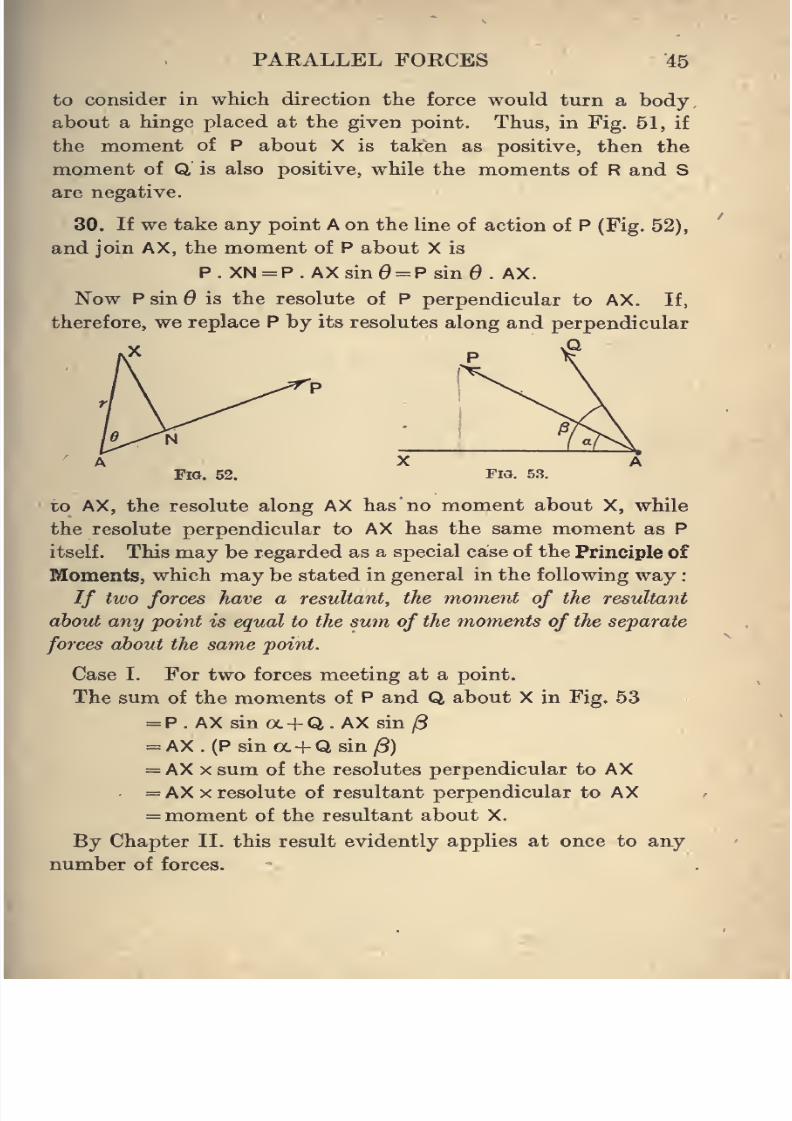
8/4/2019 Elementary Statics of 2 & Dimensions R.J.a. Barnard 1921
http://slidepdf.com/reader/full/elementary-statics-of-2-dimensions-rja-barnard-1921 57/272
PARALLEL FORCES 45
to consider in which direction the force would turn a body
about a hinge placed at the given point. Thus, in Fig. 51, if
the moment of P about X is taken as positive, then themoment of Q is also positive, while the moments of R and S
are negative.
30. If we take any point A on the line of action of P (Fig. 52),
and join AX, the moment of P about X is
P.XN = P.AXsin0 = Psin0. AX.
Now PsinOis the resolute of P
perpendicular to AX. If,
therefore, we replace P by its resolutes along and perpendicular
FW. 5.^?.
to AX, the resolute along AX has no moment about X, while
the resolute perpendicular to AX has the same moment as P
itself. This may be regarded as a special case of the Principle of
Moments, which may be stated in general in the following way
// two forces have a resultant, the moment of the resultant
about any point is equal to the sum of the moments of the separate
forces about the same point.
Case I. For two forces meeting at a point.
The sum of the moments of P and Q about X in Fig. 53
= P. AX sin a+ Q. AX sin /3
= AX . (P sin a+ Q sin ^)
= AX X sum of the resolutes perpendicular to AX= AX X resolute of resultant perpendicular to AX
= moment of the resultant about X.
By Chapter II. this result evidently applies at once to any
number of forces.
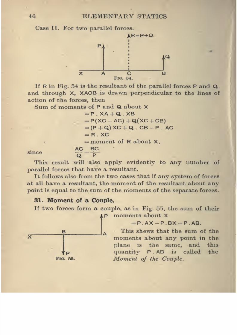
8/4/2019 Elementary Statics of 2 & Dimensions R.J.a. Barnard 1921
http://slidepdf.com/reader/full/elementary-statics-of-2-dimensions-rja-barnard-1921 58/272
46 ELEMENTARY STATICS
Case II. For two parallel forces.
AR=P+Q
AQ
Fig.
C54.
B
If R in Fig. 54 is the resultant of the parallel forces P and Q.
and through X, XACB is drawn perpendicular to the lines of
action of the forces, then
Sum of moments of P and Q about X
= P.XA + Q.XB
= P(XC - AC) +Q(XC +CB)
= (P + Q)XC + Q . CB-P . AC
= R. XC
\= moment of R about X,
AC BCsince ^=—
.
This result will also apply evidently to any number of
parallel forces that have a resultant.
It follows also from the two cases that if any system of forces
at all have a resultant, the moment of the resultant about anypoint is equal to the sum of the moments of the separate forces.
31. Moment of a Couple.
If two forces form a couple, as in Fig. 55, the sum of their
;|^P moments about X
= P.AX-P.BX = P.AB.
This shews that the sum of the
moments about any point in the
plane is the same, and this
quantity P . AB is called the
Moment of the Couple.
B
YPFig. 66.
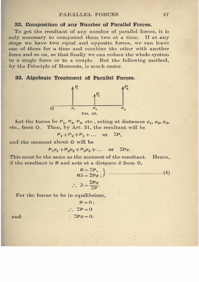
8/4/2019 Elementary Statics of 2 & Dimensions R.J.a. Barnard 1921
http://slidepdf.com/reader/full/elementary-statics-of-2-dimensions-rja-barnard-1921 59/272
PAKALLEL FORCES 47
32. Composition of any Number of Parallel Forces.
To get the resultant of any number of parallel forces, it is
only necessary to compound them two at a time. If at anystage we have two equal and opposite forces, we can leave
one of them for a time and combine the other with another
force and so on, so that finally we can reduce the whole system
to a single force or to a couple. But the following method,
by the Principle of Moments, is much easier.
33. Algebraic Treatment of Parallel Forces.
a'T jJa
/KP^
^1
Fig. 56.
Let the forces be P^, Pg, P3, etc., acting at distances Xi, x^, x^,
etc., from O. Then, by Art. 31, the resultant will be
P1+P2+P3 +- or 2P,
and the moment about O will be
Pl^l+P2^2+ P3^3+ "- ^^ ^P^-
This must be the same as the moment of the resultant. Hence,
if the resultant is R and acts at a distance x from O,
R = 2P,I
Rx= l.PxJ(4)
. -_^Px
For the forces to be in equilibrium,
R = 0;
.-. 2P =
and 2Px = 0.
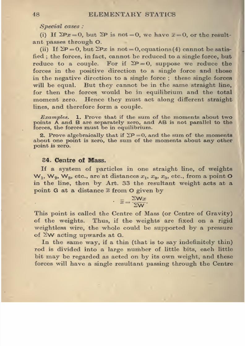
8/4/2019 Elementary Statics of 2 & Dimensions R.J.a. Barnard 1921
http://slidepdf.com/reader/full/elementary-statics-of-2-dimensions-rja-barnard-1921 60/272
48 ELEMENTARY STATICS
Special cases
(i) If 3Px = 0, but IP is not=0, we have x = 0, or the result-
ant passes through O.
(ii) If i'P = 0, but ^Px is not = 0, equations (4) cannot be satis-
fied ; the forces, in fact, cannot be reduced to a single force, but
reduce to a couple. For if 2P = 0, suppose we reduce the
forces in the positive direction to a single force and those
in the negative direction to a single force ; these single forces
will be equal. But they cannot be in the same straight line,
for then the forces would bein
equilibrium and the totalmoment zero. Hence they must act along different straight
lines, and therefore form a couple.
Examples. 1. Prove that if the sum of the moments about two
points A and B are separately zero, and AB is not parallel to the
forces, the forces must be in equilibrium.
2. Prove algebraically that if 2P =0, and the sum of the moments
about one point is zero, the sum of the moments about any otherpoint is zero.
84. Centre of Mass.
If a system of particles in one straight line, of weights
Wj, Wg, Wg, etc., are at (fistances x^, x^, Xg, etc., from a point O
in the line, then by Art. 33 the resultant weight acts at a
point G at a distance x from O given by
This point is called the Centre of Mass (or Centre of Gravity)
of the weights. Thus, if the weights are fixed on a rigid
weightless wire, the whole could be supported by a pressure
of 2)W acting upwards at G.
In the same way, if a thin (that is to say indefinitely thin)
rod is divided into a large number of little bits, each little
bit may be regarded as acted on by its own weight, and these
forces will have a single resultant passing through the Centre
at a
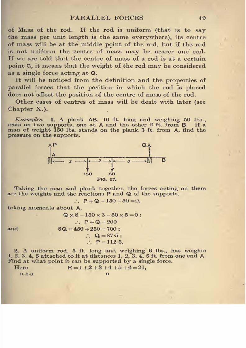
8/4/2019 Elementary Statics of 2 & Dimensions R.J.a. Barnard 1921
http://slidepdf.com/reader/full/elementary-statics-of-2-dimensions-rja-barnard-1921 61/272
PARALLEL FORCES 49
of Mass of the rod. If the rod is uniform (that is to say
the mass per unit length is the same everywhere), its centre
of mass will be at the middle point of the rod, but if the rod
is not uniform the centre of mass may be nearer one end.
If we are told that the centre of mass of a rod is at a certain
point G, it means that the weight of the rod may be considered
as a single force acting at G.
It will be noticed from the definition and the properties of
parallel forces that the position in which the rod is placed
does not affect the position of the centre of mass of the rod.
Other cases of centres of mass will be dealt with later (see
Chapter X.).
Examples. 1. A plank AB, 10 ft. long and weighing 50 lbs.,
rests on two supports, one at A and the other 2 ft. from B. If a
man of weight 150 lbs. stands on the plank 3 ft. from A, find the
pressure on the supports.
>KP QA
W^ »<--t M B
Y i150 50
Fig. 57.
Taking the man and plank together, the forces acting on them
are the weights and the reactions P and Q of the supports.
.-. P + Q- 150 -50=0,
taking moments about A,
Qx8-150x3-50x5=0;
.-. P + Q = 200
and 8Q = 450 + 250 = 700 ;
.-. Q=87-5;
.'. P = 112-5.
2. A uniform rod, 5 ft. long and weighing 6 lbs., has weights
1, 2, 3, 4, 5 attached to it at distances 1, 2, 3, 4, 5 ft. from one end A.
Find at what point it can be supported by a single force.
Here R =1 +2 +3 +4 +5 +6=21,
8/4/2019 Elementary Statics of 2 & Dimensions R.J.a. Barnard 1921
http://slidepdf.com/reader/full/elementary-statics-of-2-dimensions-rja-barnard-1921 62/272
50 ELEMENTARY STATICS
and taking moments about A,
Rx = lxl+2x2+3x3+4x4+5x5+6x2J=71,x= 71/21 =3-38,
or 3-38 ft. from A.
3. Find the resultant in magnitude and position of the following
forces :
(i) 2, -3, -3, 6, - 1 lb8.-wt. at intervals of 1 ft. along a rod.
(ii) 2, -3, -5, 6, -1 as before,
(iii) 2, - 3, - 7, 6, - 1 as before.
4. At points along a rod 4 ft. long, forces 2, -3, -4, 6, -1,
act at intervals of 1 ft. Prove that the forces are equivalent to a
couple, and find its moment.
5. A horizontal rod, 18 ins. long and weighing IJ lbs., has a
weight of 2 lbs. hung at a point 12 ins. from one end. If the ends
are supported by spring balances, find the reading of each.
6. A plank, 20 ft. long and weighing 60 lbs., rests on two supports,
one at A and the other 3 ft. from B. If a weight of 40 lbs. is placed
on the plank 6 ft. from A, find the pressure on each support.
7. A imiform horizontal beam, 20 ft. long and weighing 2 cwt.,
is supported at its ends, and carries loads of 3, 2, 5, 4 cwt. at distances
3, 7, 12, 15 ft. from one end. Find the pressures on the supports.
8. A rod AB, 10 ft. long and weighing 6 lbs., is supported at A
and at another point. A load of 1 lb. is suspended at B, and 5 lbs.
and 2 lbs. at points 2 ft. and 6 ft. from B. If the pressure on the
support at A is 4 lbs., where is the other support ?
9. Find the magnitude and line of action of the resultant of
parallel forces 3, 5, 8 in one direction, and 7 in the opposite, acting
at points A, B, C, D in a straight line, where AB = 1 ft., BC =3 ft.,
CD =4 ft.
10. A plank, 15 ft. long and weighing 30 lbs., rests on supports,
one at one end A, and the other 2| ft. from B. A boy walks along
the plank, which just begins to tilt when he is a foot from B. Find
the weight of the boy.
11. A uniform bar AB, 4 ft. long, is free to turn in a vertical plane
about a hinge at A. It is supported at any angle with the horizontal
by a vertical string attached to a point of the rod 18 inches from A.
Find the greatest weight that can be hung from B without breaking
the string, supposing the string cannot support a tension of morethan 16 Ibs.-wt.
12. A ladder, 40 ft. long and weighing IJ cwt., has its centre of
mass 16 ft. from one end. It is being carried by two men, one of
whom supports it at the heavy end, while the other supports it
4 ft. from the light end. How much of its weight does each support ?
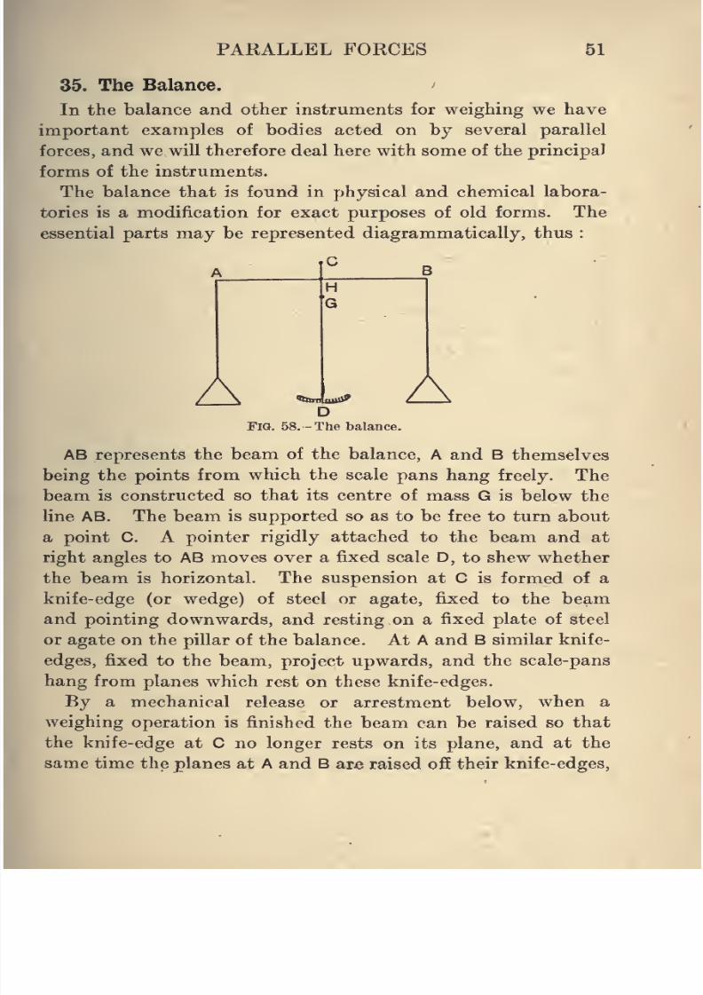
8/4/2019 Elementary Statics of 2 & Dimensions R.J.a. Barnard 1921
http://slidepdf.com/reader/full/elementary-statics-of-2-dimensions-rja-barnard-1921 63/272
PARALLEL FORCES 51
35. The Balance.
In the balance and other instruments for weighing we have
important examples of bodies acted on by several parallel
forces, and we will therefore deal here with some of the principal
forms of the instruments.
The balance that is found in physical and chemical labora-
tories is a modification for exact purposes of old forms. The
essential parts may be represented diagrammatically, thus :
AaiiX^
AFig. 58. -The balance.
AB represents the beam of the balance, A and B themselves
being the points from which the scale pans hang freely. The
beam is constructed so that its centre of mass G is below the
line AB. The beam is supported so as to be free to turn about
a point C. A pointer rigidly attached to the beam and at
right angles to AB moves over a fixed scale D, to shew whether
the beam is horizontal. The suspension at C is formed of a
knife-edge (or wedge) of steel or agate, fixed to the beam
and pointing downwards, and resting on a fixed plate of steel
or agate on the pillar of the balance. At A and B similar knife-
edges, fixed to the beam, project upwards, and the scale-pans
hang from planes which rest on these knife-edges.
By a mechanical release or arrestment below, when a
weighing operation is finished the beam can be raised so that
the knife-edge at C no longer rests on its plane, and at the
same time the planes at A and B are raised off their knife-edges.
8/4/2019 Elementary Statics of 2 & Dimensions R.J.a. Barnard 1921
http://slidepdf.com/reader/full/elementary-statics-of-2-dimensions-rja-barnard-1921 64/272
52 ELEMENTARY STATICS
and supports below the scale-pans move up for the scale-pans
to rest on.
The scale may be a millimetre scale, usually running from
to 200, with the 100 at the centre, that is, where the pointer
is when the beam is horizontal.
We will suppose at first that the balance is true. This means
that the arms AH, HB are equal, the weights of the scale-pans
are equal, and C, H, G are in a straight line perpendicular to AB.
In this case, if equal weights P, Q are placed in the scale-pans,
the beam will remain horizontal, and the pointer will come to
rest at the middle of the scale [i.e. at the 100).
However, in accurate weighing it is not usually possible to
continue trying different weights in one pan till an exact
balance is obtained. Nor is it possible to wait for the balance
to come absolutely to rest.
On account of the positions of C and G we shall see that
with any given weights in the scale-pans the balance would
come to a perfectly definite position of rest, but it actually
oscillates about this position, and the position of rest has to be
determined from the extreme positions of the pointer in the
successive oscillations.
36. Theory of the Balance.
We can now examine the relation between the inclination
of the beam and the weights in the pans.
Suppose then that the balance is true, and let
S = the weight of each scale-pan.
P, Q = the weights placed in the pans.
W = the weight of the beam.
a = the length of each arm (that is, AH = BH =a).
A;= the length CH.
Z = the length HG.
= the angle AB makes with the horizontal = GCN.
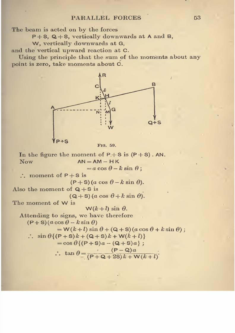
8/4/2019 Elementary Statics of 2 & Dimensions R.J.a. Barnard 1921
http://slidepdf.com/reader/full/elementary-statics-of-2-dimensions-rja-barnard-1921 65/272
PAKALLEL FORCES 53
The beam is acted on by the forces
P + S, Q + S, vertically downwards at A and B,
W, vertically downwards at G,
and the vertical upward reaction at C.
Using the principle that the sum of the moments about any
point is zero, take moments about C.
Q+S
'^P+SFig. 59.
In the figure the moment of P + S is (P + S) . AN.
Now AN = AM - H K
= a cos O-ksinO;
.'. moment of P + S is
(P + S) (a cosO-k sin 6).
Also the moment of Q + S is
(Q + S) (a cos O+kainO).
The moment of W is
V^{k + l) sin d.
Attending to signs, we have therefore
{P + S){acos6-ksui0)
=W (k + l) sin 6 + {Q + S) (a cos6 + k sin 6)
:. sind{{P + S)k + {Q + S)k + \N(k + l)}
= cos0{(P + S)a-(Q + S)a};
•• ^ (P + Q + 2S)1; + W(^ + /)'
8/4/2019 Elementary Statics of 2 & Dimensions R.J.a. Barnard 1921
http://slidepdf.com/reader/full/elementary-statics-of-2-dimensions-rja-barnard-1921 66/272
54 ELEMENTARY STATICS
From this result it will be seen that if the weights in the
scale-pans are equal, the beam remains horizontal, but that
if the weights are slightly different, the beam will take a
definite position of equilibrium which is not horizontal.
If h and I were both zero, that is, if the centre of mass of
the beam and the centre of suspension coincided and were
in the line AB, the beam could take any position when equal
weights were in the scale-pans, and would turn to a vertical
position if the weights were different. This is avoided by
having G below AB.
37. Sensitiveness of the Balance.
The ratio tan 0/(P - Q) may be taken as a measure of the
sensitiveness of the balance, which is therefore
(5)(P
+Q4-2S)A;-}-W(A;-f-0'
6 will always be small in any case of weighing, and tan 6
therefore will be nearly the same as the circular measure of Q,
and therefore will also be proportional to the number of
divisions on the scale moved over by the pointer from its
standard position. Thus the sensitiveness may be denoted
by the number of divisions in the displacement of the resting
point for a difference of weights of 1 milligramme.
The expression shews that the sensitiveness diminishes as
the weights increase.
If however k = 0, that is to say, if the three knife-edges
are in a straight line, the sensitiveness becomes
a
and is independent of the weights in the pans. This condition
is generally aimed at, but on account of slight bending of the
beam with larger loads it cannot be attained exactly. Usually
matters are so arranged that when the pans are unloaded, C
I
4
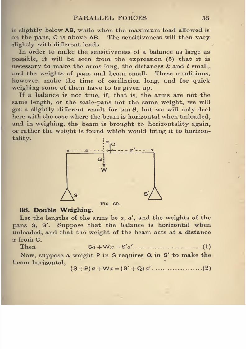
8/4/2019 Elementary Statics of 2 & Dimensions R.J.a. Barnard 1921
http://slidepdf.com/reader/full/elementary-statics-of-2-dimensions-rja-barnard-1921 67/272
PARALLEL FORCES 55
is slightly below AB, while when the maximum load allowed is
on the pans, C is above AB. The sensitiveness will then vary
slightly with different loads.
In order to make the sensitiveness of a balance as large as
possible, it will be seen from the expression (5) that it is
necessary to make the arms long, the distances k and I small,
and the weights of pans and beam small. These conditions,
however, make the time of oscillation long, and for quick
weighing some of them have to be given up.
If a balance is not true, if, that is, the arms are not the
same length, or the scale-pans not the same weight, we will
get a slightly different result for tan 0, but we will only deal
here with the case where the beam is horizontal when tinloaded,
and in weighing, the beam is brought to horizontality again,
or rather the weight is found which would bring it to horizon-
tality. •
;
..\X--'a'--
W
A AFig. 60.
38. Double Weighing.
Let the lengths of the arms be a, a', and the weights of the
pans S, S'. Suppose that the balance is horizontal when
unloaded, and that the weight of the beam acts at a distance
X from C.
Then Sa+Wa; = SV. (1)
Now, suppose a weight P in S requires Q in S' to make the
beam horizontal,
(S +P)a+Wx = (S' + Q)a' (2)
8/4/2019 Elementary Statics of 2 & Dimensions R.J.a. Barnard 1921
http://slidepdf.com/reader/full/elementary-statics-of-2-dimensions-rja-barnard-1921 68/272
56 ELEMENTARY STATICS
Now place P in S', and balance it with a weight Q' in S,
(S + Q')a+Wa; = (S'+P)a' (3)
From (1) and (2), Pa= Qa'.
From (1) and (3), Q'a = Pa'.
From these equations we can get both the true weight of P
and the ratio of the arms for
P2 = QQ' (4)
and --^ = a/I' (5)a Q ^| Q
In any ordinary case Q and Q' are very nearly equal, and it
is sufficiwitly accurate to take the arithmetic mean for the
true weight instead of the geometric mean.
For let Q' = Q + tf,
where w is very small compared with Q,
P = s/QGl' = JQ{Q~+w)
= qVI + w/Q
= Q(1 +W/2Q,) very nearly
= Q+w/2 =^t^; (6)
also a'/a = -Jq'/Q. = Jl + w/Q = 1 + —- very nearly
2Q 2Q ^r
39. Steelyards.
The Common or Roman Steelyard consists of a heavy rod
AB, supported at a fixed fulcrum C, and having a scale-pan
or hook attached at one end to carry the body, whose weight
W is required. The rod is graduated, and a weight w can be
moved along the rod, and its position when the rod is horizontal
gives the weight of the body.
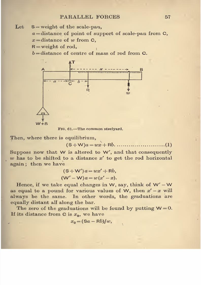
8/4/2019 Elementary Statics of 2 & Dimensions R.J.a. Barnard 1921
http://slidepdf.com/reader/full/elementary-statics-of-2-dimensions-rja-barnard-1921 69/272
PAKALLEL FORCES 57
Let S = weight of the scale-pan,
a = distance of point of support of scale-pan from C,
X = distance of w from C,
R = weight of rod,,
6 = distance of centre of mass of rod from C.
AT
— X J
llllllllllllllllllllllllll
Awh-sFig. 61.—The common steelyard.
Then, where there is equiUbrium,
(S+W)a = w:r + R6 (1)
Suppose now that W is altered to W', and that consequently
w has to be shifted to a distance x' to get the rod horizontal
again ; then we have
(S+W')a =W + R6,
(W'-W)a=w(a;'-a;).
Hence, if we take equal changes in W, say, think of W' -Was equal to a pound for various values of W, then x' -x will
always be the same. In other words, the graduations are
equally distant all along the bar.
The zero of the graduations will be found by putting W = 0,
If its distance from C is o^q, we have
Xi^ = {Sa-Rb)/w,
8/4/2019 Elementary Statics of 2 & Dimensions R.J.a. Barnard 1921
http://slidepdf.com/reader/full/elementary-statics-of-2-dimensions-rja-barnard-1921 70/272
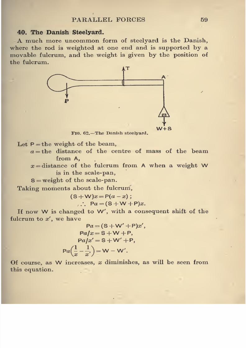
8/4/2019 Elementary Statics of 2 & Dimensions R.J.a. Barnard 1921
http://slidepdf.com/reader/full/elementary-statics-of-2-dimensions-rja-barnard-1921 71/272
PARALLEL FORCES 59
40. The Danish Steelyard.
A much more uncommon form of steelyard is the Danish,
where the rod is weighted at one end and is supported by a
movable fulcrum, and the weight is given by the position of
the fulcrum.
uT
A
i HZ
Fig. 62.—The Danish steelyard.
W+S
Let P = the weight of the beam,
a = the distance of the centre of mass of the beam
from A,
a; = distance of the fulcrum from A when a weight Wis in the scale-pan,
S = weight of the scale-pan.
Taking moments about the fulcrum,
(S+W)a; = P(a-a;);
.-. Pa = (S+W-f-P)a;.
If now W is changed to W, with a consequent shift of the
fulcrum to x', we have
Pa = (S-|-W'-f-P)a;',
Pa/a;=S+W + P,
Pa/a;' = S+W'+P,
Pa(---) =W-W.\x X /
Of course, as W increases, x diminishes, as will be seen from
this equation.
8/4/2019 Elementary Statics of 2 & Dimensions R.J.a. Barnard 1921
http://slidepdf.com/reader/full/elementary-statics-of-2-dimensions-rja-barnard-1921 72/272
60 ELEMENTARY STATICS
li W* is another weight, and x" the corresponding value of x,
Paf— --r7Vw'-W".\X
X }
Therefore, if W -W =W - W",
X x' X a;'"
or in other wbrds, if the weights are in arithmetical progression,
the distances between the corresponding graduations are in
harmonical progression.
Examples. 1. A body appears to weigh 51-474 gms. when placed
in one scale-pan of a balance, and to weigh 51-577 gms. when placed
in the other. What is its true weight and the ratio of the arms?
Also compare the true values given by equations (4) and (5), Art. 38,
with the approximate values given by (6) and (7).
2. The three knife-edges of a balance are in one straight line.
The length of the balance arm is 20 cms., the mass of the beam is
100 gms The angular deflection for a change of a centigram in the
load is 001 of the radian. Find the distance of the centre of mass
of the beam from the central knife-edge.
3. A uniform rod AB, of weight w, c^n turn about a fulcrum at a
point whose distances from the ends are a and b If a body is hung
from A it balances a weight W hung from B, and if hung from B it
balances a weight W hung from A. Find the weight of the body
in terms of W, W, a, b.
If o = 12 ins., 6 = 10 ins., W = 15 oz.,W = 16 oz., find the weight.
4. The resting point of the pointer of a balance when unloaded is
at 96. When a body is being weighed the resting point is at 130
when the weight in the scale-pan is 26-87. When the weight is 26-88
the resting-point is 18. What is the true weight to the nearest
milligram ?
5. The beam of a balance is 25 cms. long, and the pointer 30 cms.
The pointer scale is divided into millimetres. If the weight of the
beam is 200 gms. and 1 gm. moves the pointer through one division,
shew that the distance of the centre of mass of the beam below theknife-edge is 3/16 mm., the three knife-edges being in one line.
6. If the arms of a balance are a and a', and the weights of the
scale-pans S and S', other letters being as in Art. 36, prove that
Pa - Qa'tan^ =
{P + Qi + S+S')k+\N(k+l)
8/4/2019 Elementary Statics of 2 & Dimensions R.J.a. Barnard 1921
http://slidepdf.com/reader/full/elementary-statics-of-2-dimensions-rja-barnard-1921 73/272
PARALLEL FORCES 61
7. In a common steelyard the rod AB is a imiform beam of length
36 ins. and weight 3 lbs., and the fulcrum is 4 ins. from A. The
scale-pan is weighted so as to be of weight 10 lbs., and the moving
weight is 1 lb. It is graduated to quarters of a pound. Find thedistance between the graduations, the greatest weight that can be
weighed, and the position of the zero.
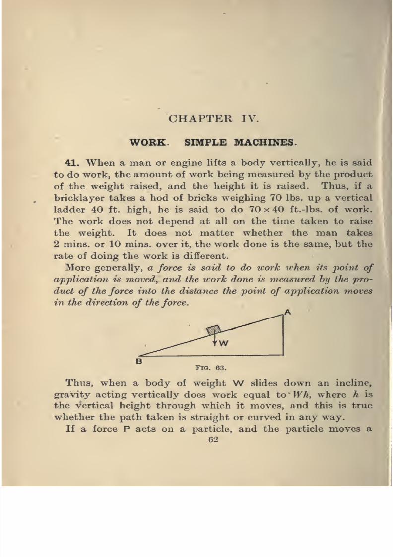
8/4/2019 Elementary Statics of 2 & Dimensions R.J.a. Barnard 1921
http://slidepdf.com/reader/full/elementary-statics-of-2-dimensions-rja-barnard-1921 74/272
CHAPTER IV.
WORE. SIMPLE MACHINES.
41. When a man or engine lifts a body vertically, he is said
to do work, the amount of work being measured by the product
of the weight raised, and the height it is raised. Thus, if a
bricklayer takes a hod of bricks weighing 70 lbs. up a vertical
ladder 40 ft. high, he is said to do 70 x 40 ft.-lbs. of work.
The work does not depend at all on the time taken to raise
the weight. It does not matter whether the man takes
2 mins. or 10 mins. over it, the work done is the same, but the
rate of doing the work is different.
More generally, a force is said to do work tohen its foint of
application is moved, and the work done is measured by the pro-
duct of the force into the distance the point of application moves
in the direction of the force.
Thus, when a body of weight W slides down an incline,
gravity acting vertically does work equal to Wh, where h is
the vertical height through which it moves, and this is true
whether the path taken is straight or curved in any way.
If a force P acts on a particle, and the particle moves a
62
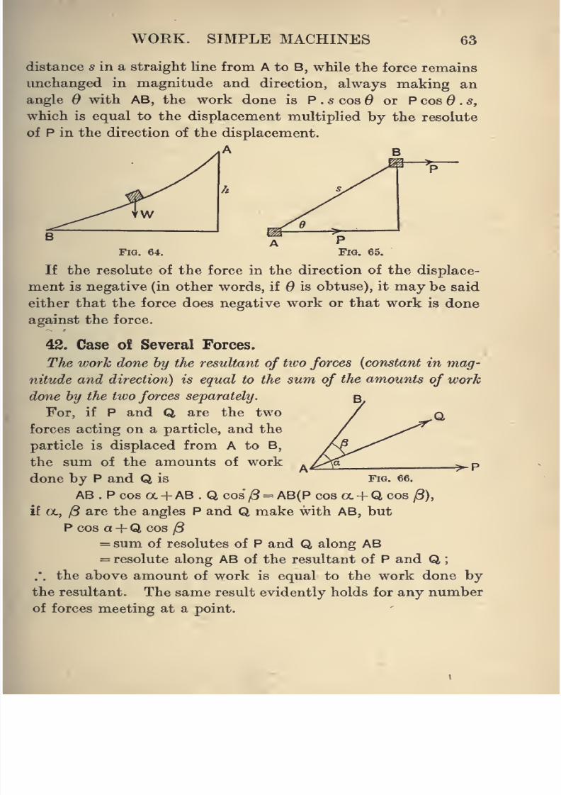
8/4/2019 Elementary Statics of 2 & Dimensions R.J.a. Barnard 1921
http://slidepdf.com/reader/full/elementary-statics-of-2-dimensions-rja-barnard-1921 75/272
WORK. SIMPLE MACHINES 63
distance s in a straight line from A to B, while the force remains
unchanged in magnitude and direction, always making an
angle d with AB, the work done is P . s cos or P cos 6 . s,
which is equal to the displacement multiplied by the resolute
of P in the direction of the displacement.
A B
If the resolute of the force in the direction of the displace-
ment is negative (in other words, if 6 is obtuse), it may be said
either that the force does negative work or that work is done
against the force.
42. Case of Several Forces.
The work done by the resultant of two forces {constant in mag-
nitude and direction) is equal to the sum of the amounts of work
done by the two forces separately. B
For, if P and Q are the two / qforces acting on a particle, and the
particle is displaced from A to B,
the sum of the amounts of work
done by P and Q is fig. 66.
AB. Pcosa + AB. Qcos/3 = AB(Pcoso(.-f QcoS|8),
if a., 13 are the angles P and Q make with AB, but
P cos a +Q cos j8
= sum of resolutes of P and Q along AB= resolute along AB of the resultant of P and Q
.'. the above amount of work is equal to the work done by
the resultant. The same result evidently holds for any number
of forces meeting at a point.
^P
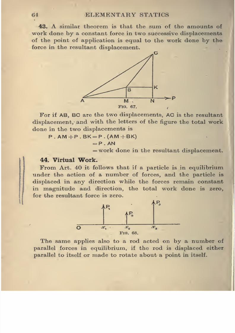
8/4/2019 Elementary Statics of 2 & Dimensions R.J.a. Barnard 1921
http://slidepdf.com/reader/full/elementary-statics-of-2-dimensions-rja-barnard-1921 76/272
64 ELEMENTARY STATICS
48. A similar theorem is that the sum of the amounts of
work done by a constant force in two successive displacements
of the point of application is equal to the work done by the
force in the resultant displacement.
^P
For if AB, BC are the two displacements, AC is the resultant
displacement, and with the letters of the figure the total work
done in the two displacements is
P.AM+P.BK = P.(AM+BK)= P . AN
= work done in the resultant displacement.
44. Virtual Work.
From Art. 40 it follows that if a particle is in equilibrium
under the action of a number of forces, and the particle is
displaced in any direction while the forces remain constantin magnitude and direction, the total work done is zero,
for the resultant force is zero.
A P.
I
Fig. 68.
The same applies also to a rod acted on by a number of
parallel forces in equilibrium, if the rod is displaced either
parallel to itself or made to rotate about a point in itself.
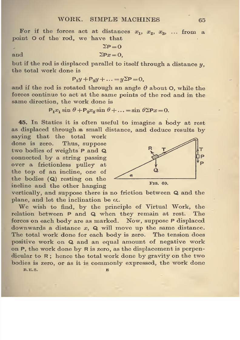
8/4/2019 Elementary Statics of 2 & Dimensions R.J.a. Barnard 1921
http://slidepdf.com/reader/full/elementary-statics-of-2-dimensions-rja-barnard-1921 77/272
WOKK. SIMPLE MACHINES 65
For if the forces act at distances Xj^, x^, x^, ... from a
point O of tlie rod, we have that
2P=0and 2Pa;=0,
but if the rod is displaced parallel to itself through a distance y,
the total work done is
and if the rod is rotated through an angle Q about O, while the
forces continue to act at the same points of the rod and in the
same direction, the work done is
Pi^i sin 6 + PgOig sin ^+ . . . = sin dlPx 0.
45. In Statics it is often useful to imagine a body at rest
as displaced through a small distance, and deduce results by-
saying that the total work
done is zero. Thus, suppose
two bodies of weights P and Qconnected by a string passing
over a frictionless pulley at
the top of an incline, one of
the bodies (Q) resting on the
incline and the other hangingvertically, and suppose there is no friction between Q and the
plane, and let the inclination be «..
We wish to find, by the principle of Virtual Work, the
relation between P and Q when they remain at rest. The
forces on each body are as marked. Now, suppose P displaced
downwards a distance x, Q will move up the same distance.
The total work done for each body is zero. The tension does
positive work on Q and an equal amount of negative work
on P, the work done by R is zero, as the displacement is perpen-
dicular to R ; hence the total work done by gravity on the two
bodies is zero, or as it is commonly expressed, the work done
B.E.S. B
Fig, 69.
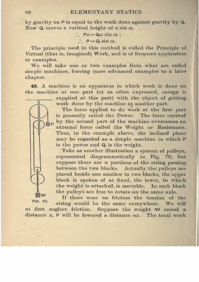
8/4/2019 Elementary Statics of 2 & Dimensions R.J.a. Barnard 1921
http://slidepdf.com/reader/full/elementary-statics-of-2-dimensions-rja-barnard-1921 78/272
66 ELEMENTARY STATICS
by gravity on P is equal to the work done against gravity by Q..
Now Q moves a vertical height of x sin ex..
.'. Px=QxsmcL;
.'. P = Q sin (X.
The principle used in this method is called the Principle of
Virtual (that is, imagined) Work, and is of frequent application
to examples.
We will take one or two examples from what are called
simple machines, leaving more advanced examples to a later
chapter.
46. A machine is an apparatus in which work is done on
the machine at one part (or as often expressed, energy is
supplied at this part) with the object of getting
work done by the machine at another part.
The force applied to do work at the first part
k
y
^y\ is generally called the Power. The force exerted
"N 1 by the second part of the machine overcomes an
y external force called the Weight or Resistance.
Thus, in the example above, the inclined plane
may be regarded as a simple machine in which P
is the power and Q is the weight.
Take as another illustration a system of pulleys,
represented diagrammatically in Fig. 70, but
suppose there are n portions of the string passing
between the two blocks. Actually the pulleys are
placed beside one another in two blocks, the upper
^J block is spoken of as fixed, the lower, to which
the weight is attached, is movable. In each block
the pulleys are free torotate on the same axle.
If there were no friction the tension of the
string would be the same everywhere. We will
at first neglect friction. Suppose the weight W raised a
distance x, P will be lowered a distance nx. The total work
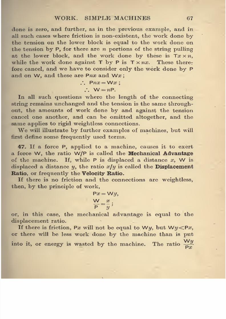
8/4/2019 Elementary Statics of 2 & Dimensions R.J.a. Barnard 1921
http://slidepdf.com/reader/full/elementary-statics-of-2-dimensions-rja-barnard-1921 79/272
WORK. SIMPLE MACHINES 67
done is zero, and further, as in the previous example, and in
all such cases where friction is non-existent, the work done by
the tension on the lower block is equal to the work done onthe tension by P, for there are n portions of the string pulling
at the lower block, and the work done by these is Tx x n,
while the work done against T by P is T x nx. These there?
fore cancel, and we have to consider only the work done by P
and on W, and these are Pnx and Wa;
.*. Pnx —Wx;
/. W = nP.
In all such questions where the length of the connecting
string remains unchanged and the tension is the same through-
out, the amounts of work done by and against the tension
cancel one another, and can be omitted altogether, and the
same applies to rigid weightless connections.
We will illustrate by further examples of machines, but will
first define some frequently used terms.
47. If a force P, applied to a machine, causes it to exert
a force W, the ratio W/P is called the Mechanical Advantage
of the machine. If, while P is displaced a distance x, W is
displaced a distance y, the ratio xjy is called the Displacement
Ratio, or frequently the Velocity Ratio.If there is no friction and the connections are weightless,
then, by the principle of work,
Px = \Ny,
"p-y'
or, in this case, the mechanical advantage is equal to the
displacement ratio.
If there is friction, Px will not be equal to Wy, but Wy<Px,
or there will be less work done by the machine than is put
W«mto it, or energy is wasted by the machine. The ratio -—
8/4/2019 Elementary Statics of 2 & Dimensions R.J.a. Barnard 1921
http://slidepdf.com/reader/full/elementary-statics-of-2-dimensions-rja-barnard-1921 80/272
68 ELEMENTARY STATICS
is then called the Efficiency. For a frictionless weightless
machine the efficiency is unity, and in no case can it be greater
than unity.
The mechanical advantage can be anything from zero to
infinity.
As a simple example take the system of pulleys already
illustrated, calling W the total weight of the moving
block and weight lifted. The displacement ratio is n, and
therefore the mechanical advantage is n if there is no
friction.
Suppose n = 4, then a weight of 100 lbs. could be lifted by
a force of 25 lbs. in the theoretical case of no friction. But in
practice the force required to raise the weight of 100 lbs. will
be greater than 25 Ibs.-wt., say it was found to be 40 Ibs.-wt.
In lifting W 1 ft., 100 ft.-lbs. of work are done, P goes down
4 ft., and 160 ft.-lbs. of work are done by P. The ratio j^g = |
is the efficiency of the system. In other words f of the work
done on (or energy supplied to) the machine is utiUzed, the
remaining f being wasted.
48. The Wheel and Axle.
Awheel is capable of rotation about a horizontal axis, and
a weight W to be raised is attached to one
end of a rope wound round the axle, the
other end of the rope being fixed to the
axle. The force P is applied tangentially
to the wheel.
In this case it is best to consider a
complete rotation of the wheel. If the
radii of the wheel and axle are a and b,
in one revolution of the wheel P descends
a distance 27ra, and W rises a distance
The displacement ratio is therefore a/6.x6..
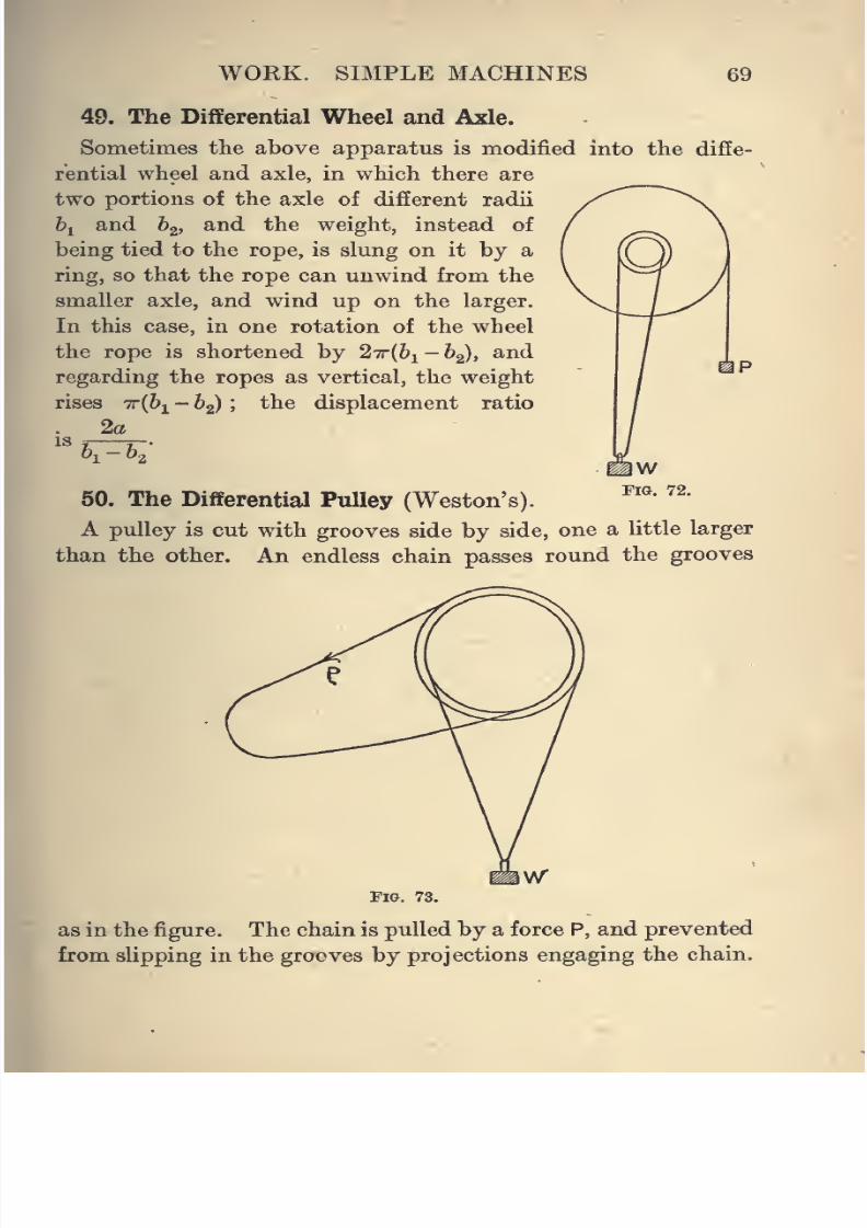
8/4/2019 Elementary Statics of 2 & Dimensions R.J.a. Barnard 1921
http://slidepdf.com/reader/full/elementary-statics-of-2-dimensions-rja-barnard-1921 81/272
WORK. SIMPLE MACHINES 69
49. The Differential Wheel and Axle.
Sometimes the above apparatus is modified into the diffe-
rential wheel and axle, in which there are
two portions of the axle of different radii
bi and &2j ^^^ ^^^ weight, instead of
being tied to the rope, is slung on it by a
ring, so that the rope can unwind from the
smaller axle, and wind up on the larger.
In this case, in one rotation of the wheel
the rope is shortened by 27r{hi-b2), and
regarding the ropes as vertical, the weight
rises 7r(6i - 63) Ithe displacement ratio
2aIS
61-62
50. The Differential Pulley (Weston's).
A pulley is cut with grooves side by side, one a little larger
than the other. An endless chain passes round the grooves
Fig. 73.
as in the figure. The chain is pulled by a force P, and prevented
from slipping in the grooves by projections engaging the chain.
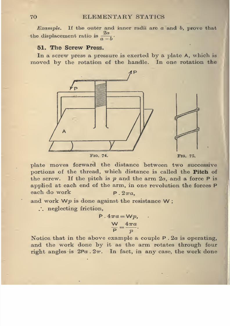
8/4/2019 Elementary Statics of 2 & Dimensions R.J.a. Barnard 1921
http://slidepdf.com/reader/full/elementary-statics-of-2-dimensions-rja-barnard-1921 82/272
70 ELEMENTARY STATICS
Example. If the outer and inner radii are a and h, prove that
the displacement ratio is —^z-
51. The Screw Press.
In a screw press a pressure is exerted by a plate A, which is
moved by the rotation of the handle. In one rotation the
Fig, 74. FlQ. 75.
plate moves forward the distance between two successive
portions of the thread, which distance is called the Pitch of
the screw. If the pitch is jp and the arm 2a, and a force P is
applied at each end of the arm, in one revolution the forces P
each do work p . ^ira,
and work Wj? is done against the resistance W;
.', neglecting friction,
P . iira = W;p,
P~
f'
Notice that in the above example a couple P . 2a is operating,
and the work done by it as the arm rotates through four
right angles is 2Pa . 27r. In fact, in any case, the work done
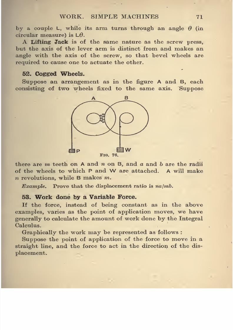
8/4/2019 Elementary Statics of 2 & Dimensions R.J.a. Barnard 1921
http://slidepdf.com/reader/full/elementary-statics-of-2-dimensions-rja-barnard-1921 83/272
WOKK. SIMPLE MACHINES 71
by a couple L, wiile its arm turns through an angle 6 (in
circular measure) is L6.
A Lifting Jack is of the same nature as the screw press,
but the axis of the lever arm is distinct from and makes an
angle with the axis of the screw, so that bevel wheels are
required to cause one to actuate the other.
52. Cogged Wheels.
Suppose an arrangement as in the figure A and B, each
consisting of two wheels fixed to the same axis. Suppose
A B
Fig. 76.
there are m teeth on A and w on B, and a and h are the radii
of the wheels to which P and W are attached. A will make
n revolutions, while B makes m.
Example. Prove that the displacement ratio is nalmh.
53. Work done by a Variable Force.
If the force, instead of being constant as in the above
examples, varies as the point of application moves, we have
generally to calculate the amount of work done by the Integral
Calculus.
Graphically the work may be represented as follows :
Suppose the point of application of the force to move in a
straight line, and the force to act in the direction of the dis-
placement.
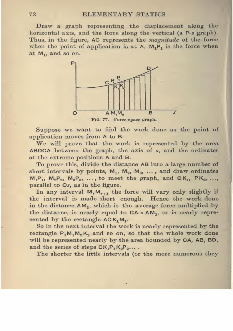
8/4/2019 Elementary Statics of 2 & Dimensions R.J.a. Barnard 1921
http://slidepdf.com/reader/full/elementary-statics-of-2-dimensions-rja-barnard-1921 84/272
72 ELEMENTARY STATICS
Draw a graph representing the displacement along the
horizontal axis, and the force along the vertical (a P-s graph).
Thus, in the figure, AC represents the magnitude of the force
when the point of application is at A, MjPi is the force when
at M,, and so on.
A M,M^ B
Fig. 77.—Force-space graph.
Suppose we want to fiiid the work done as the point of
application moves from A to B.
We will prove that the work is represented by the area
ABDCA between the graph, the axis of s, and the ordinates
at the extreme positions A and B.
To prove this, divide the distance AB into a large number of
short intervals by points, Mj, Mg, Mg, ... , and draw ordinates
MiPi, M2P2, M3P3 to meet the graph, and CKj, PKj
parallel to Os, as in the figure.
In any interval M^M^^j the force will vary only slightly if
the interval is made short enough. Hence the work done
in the distance AM^, which is the average force multiplied by
the distance, is nearly equal to CAxAMj, or is nearly repre-
sented by the rectangle ACK^Mi.
So in the next interval the work is nearly represented by the
rectangle P^IA^IA^K^ and so on, so that the whole work done
will be represented nearly by the area bounded by CA, AB, BD,
and the series of steps CKiPiKgPg-..
.
The shorter the little intervals (or the more numerous they
8/4/2019 Elementary Statics of 2 & Dimensions R.J.a. Barnard 1921
http://slidepdf.com/reader/full/elementary-statics-of-2-dimensions-rja-barnard-1921 85/272
WORK. SIMPLE MACHINES 73
are) the more accurate will this representation become, and
also the nearer will the series of steps be to coincidence
with the graph itself.
Hence, when we make the number of intervals indefinitely
large, we have the result that the work will be accurately
represented by the area between the graph, the ordinates,
and the axis of s.
The representation of the work by an area must be under-
stood in the following way. Suppose on squared paper the
side of a square in the horizontal direction represents a distance
of one foot, and the same length in the vertical direction
represents a force of 5 Ibs.-wt., then a unit square will represent
5 ft.-lbs. of work, and similarly in any case.
54. Springs and Extensible Springs.
The only case we shall examine of work done by a variable
force is where a spiral spring or an elastic string is stretched.
We have already mentioned that when an elastic string is fixed
at one end and a weight is hung at the other, the string is found
to increase in length, and the extension of the string is pro-
portional to the weight applied, that is, to the stretching force
or the tension of the string. This is a case of Hooke's Law.
The extension for different strings of the same material is also
found to be proportional to the length of the string and in-
versely proportional to its cross section.
PiThus the extension is proportional to —, where P is the force
applied. A is the area of cross section, I the length when
unstretched.
If we call s the extension, we can therefore write
Pi
where E is a constant for the material and is called Young's
Modulus.
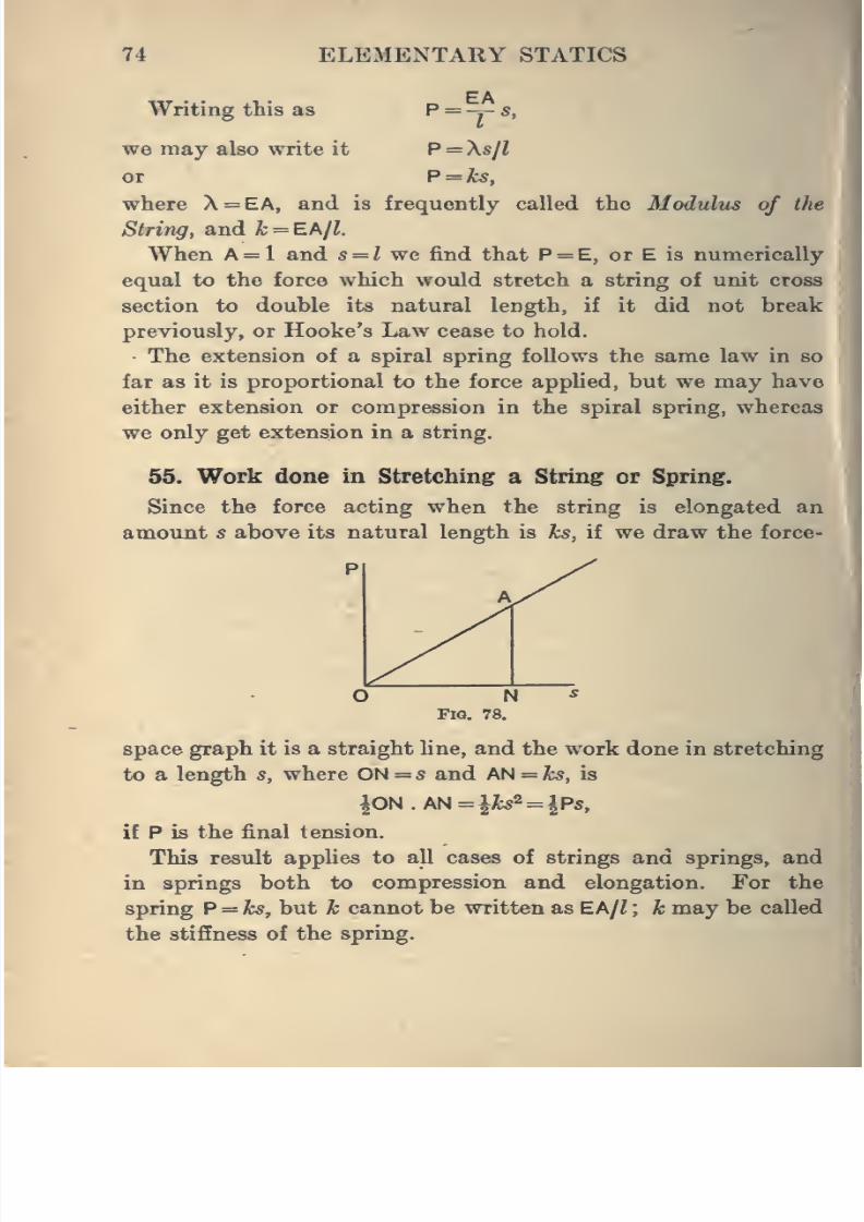
8/4/2019 Elementary Statics of 2 & Dimensions R.J.a. Barnard 1921
http://slidepdf.com/reader/full/elementary-statics-of-2-dimensions-rja-barnard-1921 86/272
74 ELEMENTARY STATICS
Writing this as P = -,- s,
we may also write it P = Xs/l
or P = ks,
where X = EA, and is frequently called the Modulus of the
String, and k = EA/Z.
When A = 1 and s= l yre find that P = E, or E is numerically
equal to the force which would stretch a string of unit cross
section to double its natural length, if it did not break
previously, or Hooke's Law cease to hold.
The extension of a spiral spring follows the same law in so
far as it is proportional to the force appUed, but we may have
either extension or compression in the spiral spring, whereas
we only get extension in a string.
55. Work done in Stretching a String or Spring.
Since the force acting when the string is elongated an
amount s above its natural length is ks, if we draw the force-
FlQ. 78.
space graph it is a straight line, and the work done in stretching]
to a length s, where ON = s and AN = ks, is
^0N.AN=^Jb2 = |P5,
if P is the finaltension.
This result applies to all cases of strings and springs, and
in springs both to compression and elongation. For the
spring P = ks, but k cannot be written as EAjl ; k may be called
the stiffness of the spring.
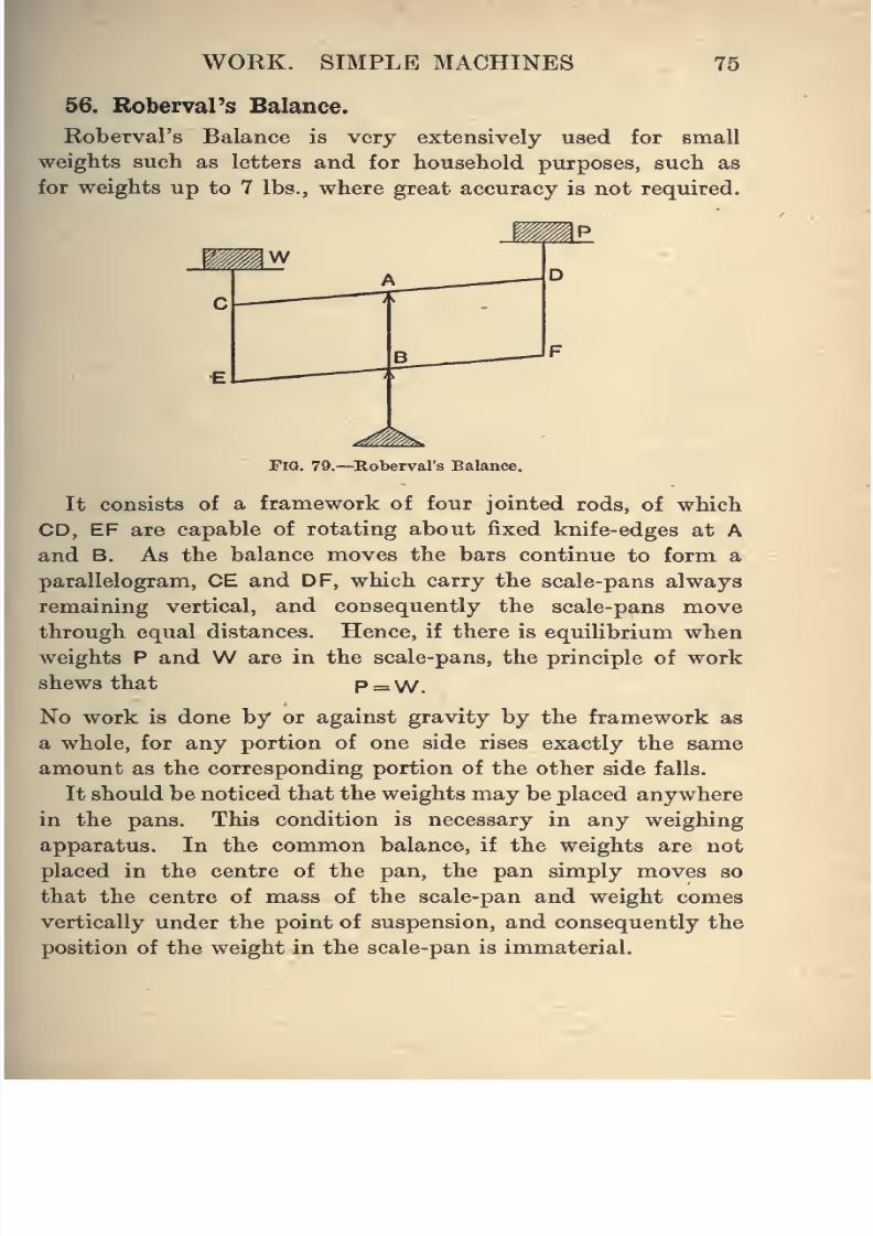
8/4/2019 Elementary Statics of 2 & Dimensions R.J.a. Barnard 1921
http://slidepdf.com/reader/full/elementary-statics-of-2-dimensions-rja-barnard-1921 87/272
WORK. SIMPLE MACHINES 75
56. Roberval's Balance.
Roberval's Balance is very extensively used for small
weights such as letters and for household purposes, such as
for weights up to 7 lbs., where great accuracy is not required.
FiQ. 79.—Roberval's Balance.
It consists of a framework of four jointed rods, of whichCD, EF are capable of rotating about fixed knife-edges at A
and B. As the balance moves the bars continue to form a
parallelogram, CE and DF, which carry the scale-pans always
remaining vertical, and consequently the scale-pans move
through equal distances. Hence, if there is equilibrium when
weights P and W are in the scale-pans, the principle of work
shews that P = W.
No work is done by or against gravity by the framework as
a whole, for any portion of one side rises exactly the same
amount as the corresponding portion of the other side falls.
It should be noticed that the weights may be placed anywhere
in the pans. This condition is necessary in any weighing
apparatus. In the common balance, if the weights are notplaced in the centre of the pan, the pan simply moves so
that the centre of mass of the scale-pan and weight comes
vertically under the point of suspension, and consequently the
position of the weight in the scale-pan is immaterial.
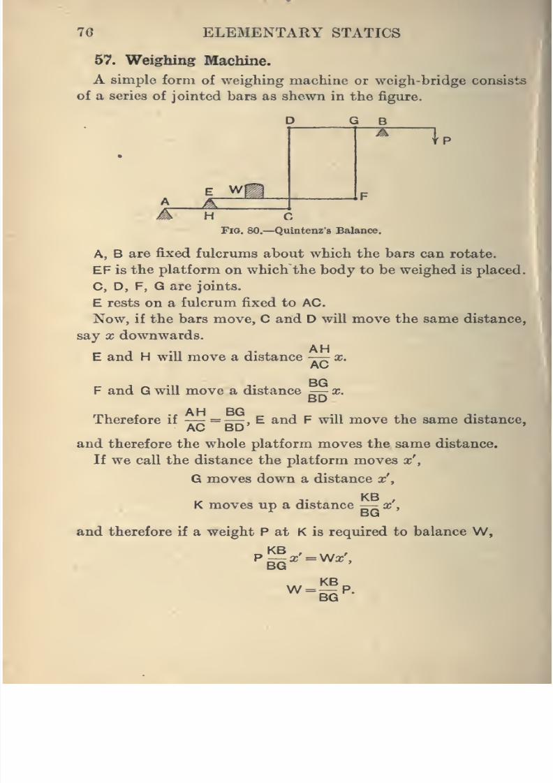
8/4/2019 Elementary Statics of 2 & Dimensions R.J.a. Barnard 1921
http://slidepdf.com/reader/full/elementary-statics-of-2-dimensions-rja-barnard-1921 88/272
76 ELEMENTARY STATICS
57. Weighing Machine.
A simple form of weighing machine or weigh-bridge consists
of a series of jointed bars as shewn in the figure.
D G
f P
H CFio. 80.—Quintenz'3 Balance.
A, B are fixed fulcrums about which the bars can rotate.
EF is the platform on which the body to be weighed is placed.
C, D, F, G are joints.
E rests on a fulcrum fixed to AC.
Now, if the bars move, C and D will move the same distance,
say X downwards.
AHE and H will move a distance —-r x.
AC
F and G will move a distance —- x.BD
AH ROTherefore if —r. =zrir, E and F will move the same distance,
AC BD'
'
and therefore the whole platform moves the same distance.
If we call the distance the platform moves x',
Q moves down a distance x',
K moves up a distance — x',
and therefore if a weight P at K is required to balance W,
W = ^P.BG
i
8/4/2019 Elementary Statics of 2 & Dimensions R.J.a. Barnard 1921
http://slidepdf.com/reader/full/elementary-statics-of-2-dimensions-rja-barnard-1921 89/272
WORK. SIMPLE MACHINES 77
As the whole platform moves the same distance, it does
not matter on what portion of it the load is placed.
Often this balance is made with KB = 10 BG, and is then
called a Decimal Balance.
The work done by the parts of the machine is not taken into
account in the above theory.
EXAMPLES.
1. In the system of pulleys in which a single string passes round
the tAVO blocks, there are six portions of the string between the two.
What is the displacement ratio ? If the efficiency of the apparatus
is 30 per cent., what energy has to be supplied to raise a weight of
150 lbs. 20 ft. ?
2. If the lower block contains two pulleys and weighs 2 lbs.
and the upper block contains three, what would the mechanical
advantage be in raising a 20 lb. weight if there were no friction,
and what energy is wasted in raising it 10 ft. if a force of 6 lbs. is
actually required ?
3. A fixed pulley and a single movable one are used for raising
a weight of 200 lbs. If the efficiency is 64 per cent., what force
will be exerted, and how much energy is expended in raising the
weight 20 ft. ?
4. A man suspends himself by standing in a bucket at one end of
a rope, and pulling at the other end. IfW is the weight of the man,
andW of the bucket, find the tension of the rope and the pressure
of the man on the bucket.
5. Two painters seated on a plank haul themselves up by
means of a block and tackle at each end of the plank. If each
man weighs 10 stone, and the plank and lower blocks weigh a cwt.,
and there are three sheaves m each block, find the pull each manmust exert, and his pressure on the plank, neglecting friction.
6. The handle of a winch has a radius of 18 ins., and the drum
is 6 ins. in diameter. Fmd the force on the handle necessary to
give a pull of 2 cwt. on the rope. Explain how gear wheels may be
used, so that the same force on the handle would give a pull ofhalf a ton.
7. A bucket of weight 50 lbs. is raised by a windlass whose
dimensions are as in Question 6. What force would be required if
there were no friction ? What is the efficiency if the force actually
required is 12 Ibs.-wt. ?
8/4/2019 Elementary Statics of 2 & Dimensions R.J.a. Barnard 1921
http://slidepdf.com/reader/full/elementary-statics-of-2-dimensions-rja-barnard-1921 90/272
78 ELEMENTARY STATICS
8. An ordinary winch is used to lift a weight of 112 lbs. The
length of the handle is 20 ins., and the diameter of the barrel of the
winch is 8 ins. What force on the handle would be required to
raise the weight if there were no friction ?
If a force of 30 lbs. is actually required, find the energy wastedon account of friction in raising the weight 20 ft.
9. In a differential wheel and axle the two parte of the axle
are of radii 4 and 5 ins., and the force is applied at the end of an
arm 18 ins. long. To raise a weight of 2000 lbs. a force of 96 lbs.
is required. What is the efficiency ?
10. In a differential wheel and axle the two parts of the rope
on which the weightW is slung make an angle 2a. with one another,
and a, b, r are the radii of the two parts of the axle and of the wheel.Prove that Pr =
JW (6 - a) sec o.,
neglecting friction.
11. The handle of a screw press is 20 ins. long, and the screw
advances \ in. in each complete revolution. Find the pressure
exerted by the press when a force of 12 Ibs.-wt. is applied at each
end of the handle. Find also the work done in a complete revolution
of the handle (neglect friction).
12. What will the pitch of the screw press be if the handle is 2 ft.
long, and a force of 10 Ibs.-wt. applied at each end of the handle
causes a pressure of 5000 Ibs.-wt. to be exerted by the press (neglect
friction) ?
13. Two screws of pitches p and p' are cut on the same cylinder.
The first works in a fixed nut, the second on a nut that can movelongitudinally, but is prevented from turning. The driving force
is applied at the end of an arm of length h ; the resistance acts on
the movable nut. Find the ratio of driving force to resistance.
14. A body is pulled up a rough incline AB by a force P parallel
to the plane. Shew that the work done is equal to the sum of the
work done in pulling the body by a horizontal force along an equally
rough horizontal plane equal to the base AC, and then lifting it
vertically from C to B.
15. A weight of 260 lbs. is pulled up a plane of length 13 ft. and
height 5 ft. Find the force exerted and the work done if the co-
efficient of friction is 0-5
(i) when the force is parallel to the plane ;
(ii) when it is horizontal
(iii) when the least possible force is used (see Art. 22j Ex. 5).
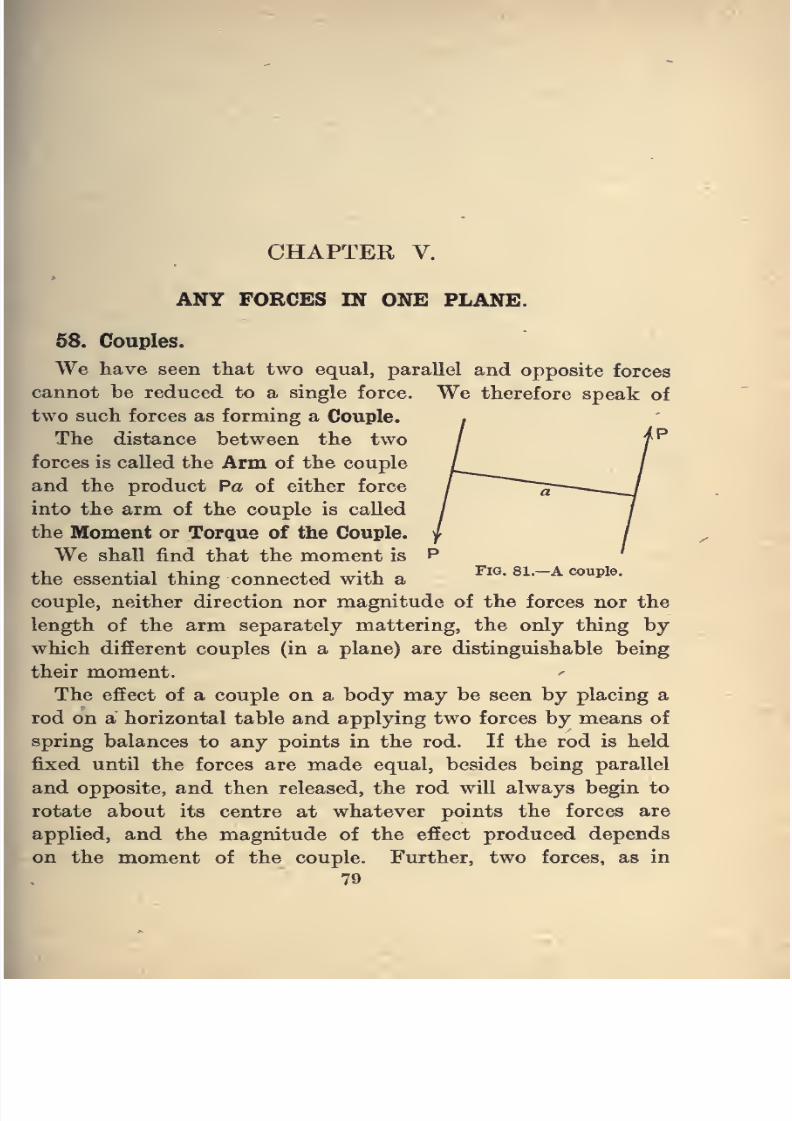
8/4/2019 Elementary Statics of 2 & Dimensions R.J.a. Barnard 1921
http://slidepdf.com/reader/full/elementary-statics-of-2-dimensions-rja-barnard-1921 91/272
CHAPTER V.
ANY FORCES IN ONE PLANE.
58. Couples.
We have seen that two equal, parallel and opposite forces
cannot be reduced to a single force. We therefore speak of
two such forces as forming a Couple.
The distance between the two
forces is called the Arm of the couple
and the product Pa of either force
into the arm of the couple is called
the Moment or Torque of the Couple.
We shall find that the moment is
the essential thing connected with a^^' '~ *^"p®-
couple, neither direction nor magnitude of the forces nor the
length of the arm separately mattering, the only thing by
which different couples (in a plane) are distinguishable being
their moment.
The effect of a couple on a body may be seen by placing a
rod on a horizontal table and applying two forces by means of
spring balances to any points in the rod. If the rod is held
fixed until the forces are made equal, besides being parallel
and opposite, and then released, the rod will always begin to
rotate about its centre at whatever points the forces are
applied, and the magnitude of the effect produced depends
on the moment of the couple. Further, two forces, as in
79
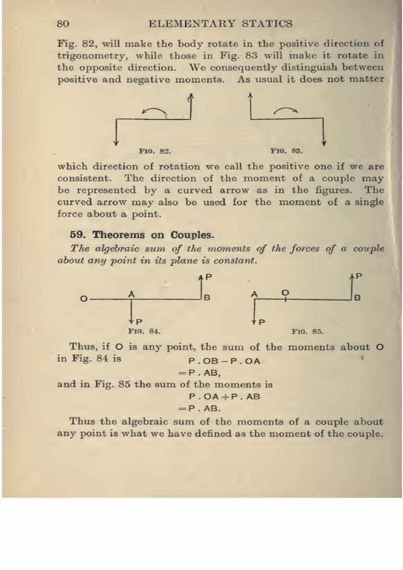
8/4/2019 Elementary Statics of 2 & Dimensions R.J.a. Barnard 1921
http://slidepdf.com/reader/full/elementary-statics-of-2-dimensions-rja-barnard-1921 92/272
80 ELEMENTARY STATICS
Fig. 82, will make the body rotate in the positive direction of
trigonometry, while those in Fig. 83 will make it rotate in
the opposite direction. We consequently distinguish between
positive and negative moments. As usual it does not matter
FlO. 82. Fig. 83.
which direction of rotation we call the positive one if we are
consistent. The direction of the moment of a couple may
be represented by a curved arrow as in the figures. The
curved arrow may also be used for the moment of a single
force about a point.
59. Theorems on Couples.
The algebraic sum of the moments of tJie forces of a couple
about any point in its plane is constant.
tPFig. 84. Fig. 85.
Thus, if O is any point, the sum of the moments abou
in Fig. 84 is P . OB - P . OA
= P. AB,
and in Fig. 85 the sum of the moments is
P.OA + P. AB
= P.AB.
Thus the algebraic sum of the moments of a couple about
any point is what we have defined as the moment of the couple
i
J
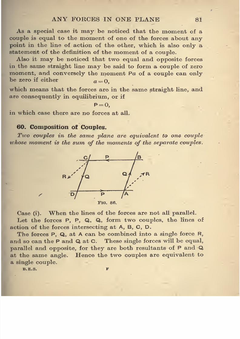
8/4/2019 Elementary Statics of 2 & Dimensions R.J.a. Barnard 1921
http://slidepdf.com/reader/full/elementary-statics-of-2-dimensions-rja-barnard-1921 93/272
ANY FORCES IN ONE PLANE 81
As a special case it may be noticed that the moment of a
couple is equal to the moment of one of the forces about any
point in the line of action of the other, which is also only astatement of the definition of the moment of a couple.
Also it may be noticed that two equal and opposite forces
in the same straight line may be said to form a couple of zero
moment, and conversely the moment Pa of a couple can only
be zero if either a=0
which means that the forces are in the same straight line, and
are consequently in equilibrium, or if
P = 0,
in which case there are no forces at all.
60. Composition o£ Couples.
Tivo couples in the same plane are equivalent to one couple
whose moment is the sum of the moments of the separate couples.
Case (i). When the lines of the forces are not all parallel.
Let the forces P, P, Q, Q, form two couples, the lines of
action of the forces intersecting at A, B, C, D.
The forces P, Q, at A can be combined into a single force R,
and so can the P and Q at C. These single forces will be equal,
parallel and opposite, for they are both resultants of P and Q
at the same angle. Hence the two couples are equivalent to
a single couple.
B.E,S. F
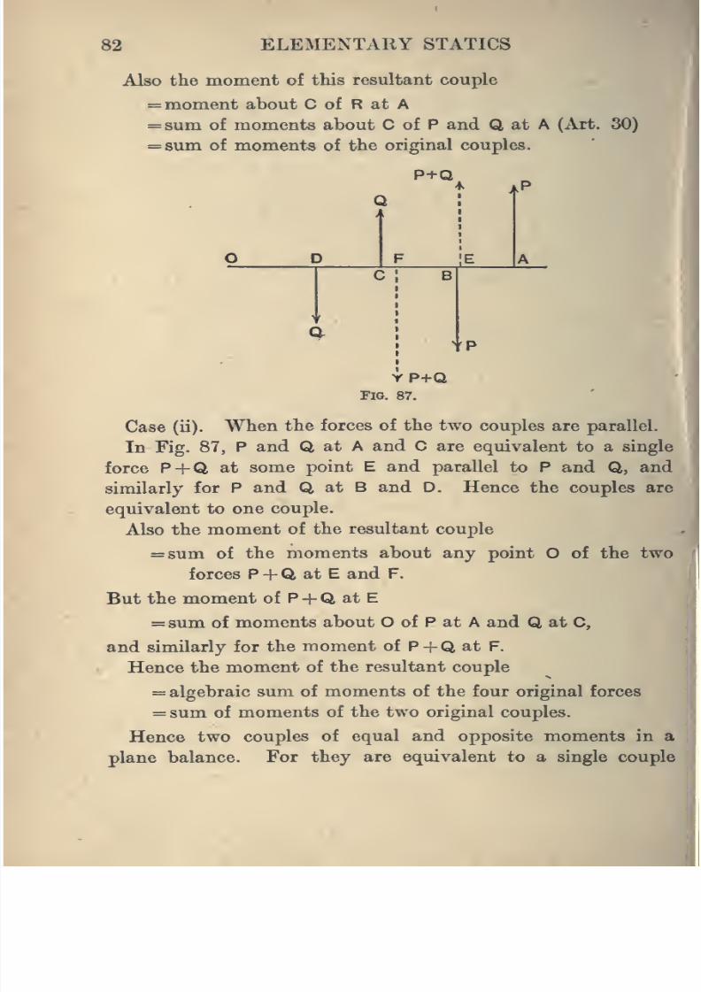
8/4/2019 Elementary Statics of 2 & Dimensions R.J.a. Barnard 1921
http://slidepdf.com/reader/full/elementary-statics-of-2-dimensions-rja-barnard-1921 94/272
82 ELEMENTARY STATICS
Also the moment of this resultant couple
= moment about C of R at A
= sum of moments about C of P and Q at A (Art. 30)
=8um of moments of the original couples.
P+Q
tP
YP+QFIO. 87.
Case (ii). When the forces of the two couples are parallel.
In Fig. 87, P and Q at A and C are equivalent to a single
force P +Q at some point E and parallel to P and Q, and
similariy for P and Q at B and D. Hence the couples are
equivalent to one couple.
Also the moment of the resultant couple
=8um of the moments about any point O of the twc
forces P +Q at E and F.
But the moment of P +Q at E
= sum of moments about O of P at A and Q at C,
and similarly for the moment of P+Q at F.
Hence the moment of the resultant couple
= algebraic sum of moments of the four original forces
= sum of moments of the two original couples.
Hence two couples of equal and opposite moments in
plane balance. For they are equivalent to a single couplfl
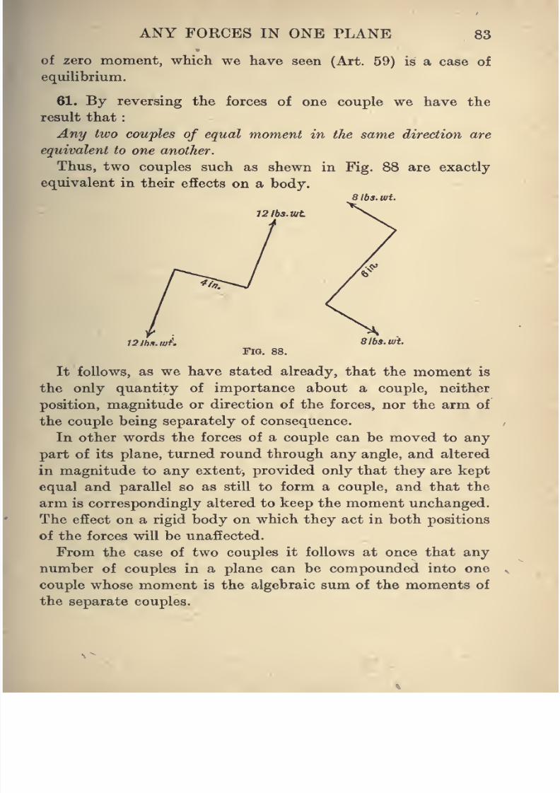
8/4/2019 Elementary Statics of 2 & Dimensions R.J.a. Barnard 1921
http://slidepdf.com/reader/full/elementary-statics-of-2-dimensions-rja-barnard-1921 95/272
ANY FORCES IN ONE PLANE 83
of zero moment, wMch we have seen (Art. 59) is a case of
equilibrium.
61. By reversing the forces of one couple
we havethe
result that
Any two couples of equal moment in the same direction are
equivalent to one another.
Thus, two couples such as shewn in Fig. 88 are exactly
equivalent in their effects on a body.
aibs.wt.
12lbs.ujt
12lh.i.iJjf'. SibS.wt.
Fig. 88.
It follows, as we have stated already, that the moment is
the only quantity of importance about a couple, neither
position, magnitude or direction of the forces, nor the arm of
the couple being separately of consequence.
In other words the forces of a couple can be moved to any
part of its plane, turned round through any angle, and altered
in magnitude to any extent, provided only that they are kept
equal and parallel so as still to form a couple, and that the
arm is correspondingly altered to keep the moment unchanged.
The effect on a rigid body on which they act in both positions
of the forces will be unaffected.
From the case of two couples it follows at once that any
number of couples in a plane can be compounded into one
couple whose moment is the algebraic sum of the moments of
the separate couples.
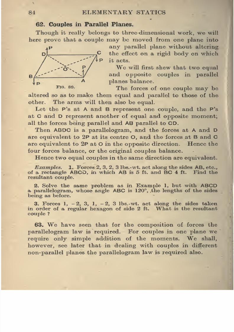
8/4/2019 Elementary Statics of 2 & Dimensions R.J.a. Barnard 1921
http://slidepdf.com/reader/full/elementary-statics-of-2-dimensions-rja-barnard-1921 96/272
84 ELEMENTARY STATICS
62. Couples in Parallel Planes.
Though it really belongs to three dimensional work, we will
here prove that a couple may be moved from one plane into
any parallel plane without altering
the efEect on a rigid body on which
it acts.
-Q^x P/ We will first shew that two equal
and opposite couples in parallel
planes balance.
*^'°- ®^-
Theforces of
onecouple
maybe
altered so as to make them equal and parallel to those of the
other. The arms will then also be equal.
Let the P's at A and B represent one couple, and the P's
at C and D represent another of equal and opposite moment,
all the forces being parallel and AB parallel to CD.
Then ABDC is a parallelogram, and the forces at A and D
are equivalent to 2P at its centre O, and the forces at B and Care equivalent to 2P at O in the opposite direction. Hence the
four forces balance, or the original couples balance.
Hence two equal couples in the same direction are equivalent.
Examples. 1. Forces 2, 3, 2, 3 Ibs.-wt. act along the sides AB, etc.,
of a rectangle ABCD, in which AB is 5 ft. and BC 4 ft. Find the
resultant couple.
2. Solve the same problem as in Example 1, but with ABCDa parallelogram, whose angle ABC is 120°, .the lengths of the sides
being as before.
3. Forces 1, -2, 3, 1, -2, 3 Ibs.-wt. act along the sides taken
in order of a regular hexagon of side 2 ft. What is the resultant
couple ?
63. We have seen that for the composition of forces the
parallelogram law is required. For couples in one plane we
require only simple addition of the moments. We shall,
however, see later that in dealing with couples in different
non-parallel planes the parallelogram law is required also.
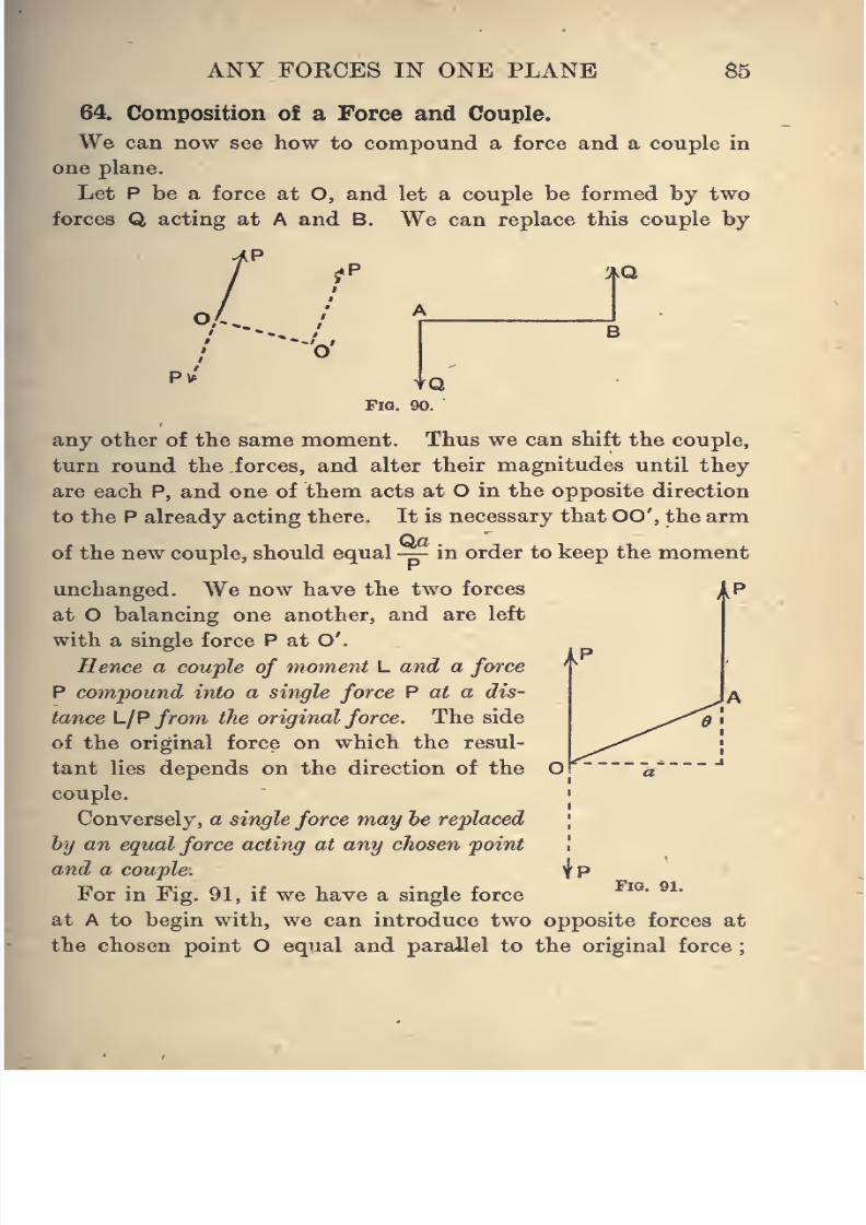
8/4/2019 Elementary Statics of 2 & Dimensions R.J.a. Barnard 1921
http://slidepdf.com/reader/full/elementary-statics-of-2-dimensions-rja-barnard-1921 97/272
ANY FORCES IN ONE PLANE 85
64. Composition of a Force and Couple.
We can now see how to compound a force and a couple in
one plane.
Let P be a force at O, and let a couple be formed by two
forces Q acting at A and B. We can replace this couple by
%Q,
"O'
Fia. 90.
any other of the same moment. Thus we can shift the couple,
turn round the forces, and alter their magnitudes until they
are each P, and one of them acts at O in the opposite direction
to the P already acting there. It is necessary that 00', the arm
of the new couple, should equal— in order to keep the moment
unchanged. We now have the two forces
at O balancing one another, and are left
with a single force P at O'.
Hence a couple of moment L and a forceP compound into a single force P at a dis-
tance L/P from the original force. The side
of the original force on which the resul-
tant lies depends on the direction of the
couple.
Conversely, a single force may he replaced
by an equal force acting at any chosen point
and a couple.
For in Fig. 91, if we have a single force
at A to begin with, we can introduce two opposite forces at
the chosen point O equal and parallel to the original force
hFig. 91.
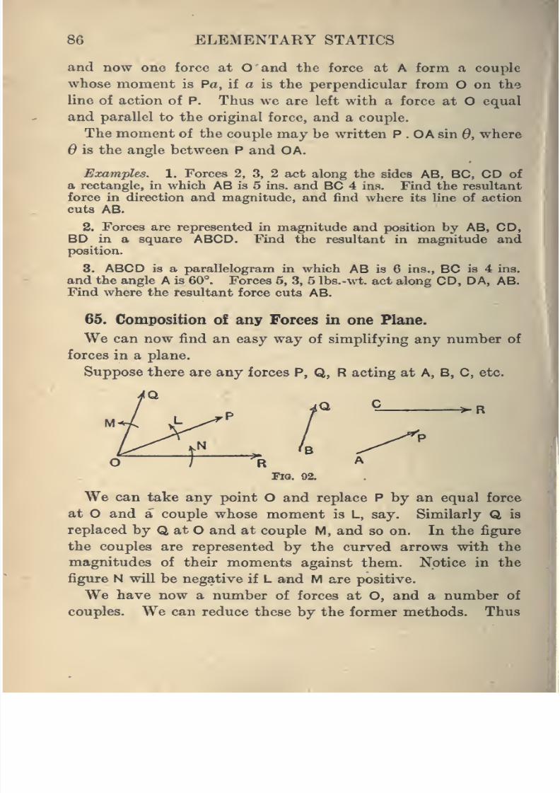
8/4/2019 Elementary Statics of 2 & Dimensions R.J.a. Barnard 1921
http://slidepdf.com/reader/full/elementary-statics-of-2-dimensions-rja-barnard-1921 98/272
86 ELEMENTAKY STATICS
and now one force at O and the force at A form a couple
whose moment is Pa, if a is the perpendicular from O on the
line of action of P. Thus we are left with a force at O equal
and parallel to the original force, and a couple.
The moment of the couple may be written P . OA sin 0, where
6 is the angle between P and OA.
Examples. 1. Forces 2, 3, 2 act along the sides AB, BC, CD of
a rectangle, in which AB is 5 ins. and BC 4 ins. Find the resultant
force in direction and magnitude, and find where its line of action
cuts AB.
2. Forces are represented in magnitude and position by AB, CD,
BD in a square ABCD. Find the resultant in magnitude andposition.
3. ABCD is a parallelogram in which AB is 6 ins., BC is 4 ins.
and the angle A is 60°. Forces 5, 3, 5 Ibs.-wt. act along CD, DA, AB.
Find where the resultant force cuts AB.
65. Composition of any Forces in one Plane.
We can now find an easy way of simplifying any number of
forces in a plane.
Suppose there are any forces P, Q, R acting at A, B, C, etc.
"4 t^"
^R
^—r%
Fig. 92.
We can take any point O and replace P by an equal force
at O and a couple whose moment is L, say. Similarly Q is
replaced by Q at O and at couple M, and so on. In the figure
the couples are represented by the curved arrows with the
magnitudes of their moments against them. Notice in the
figure N will be negative if L and M are positive.
We have now a number of forces at O, and a number of
couples. We can reduce these by the former methods. Thus
8/4/2019 Elementary Statics of 2 & Dimensions R.J.a. Barnard 1921
http://slidepdf.com/reader/full/elementary-statics-of-2-dimensions-rja-barnard-1921 99/272
ANY FOECES IN ONE PLANE 87
*
the forces at O can be reduced to a single force and the couples
reduce to one couple. Either the single force or the couple
or both may happen to be zero.
Hence we are left with
(i) a single force or (ii) zero,
together with
(iii) a couple or (iv) zero.
Now, if we have (i) and (iii), we can further reduce them to
a single force :
(i) and (iv) also give a single force,
(ii) and (iii) give a couple,
(ii) and (iv) give zero.
Thus we have the result that any system of forces whatever
in a plane can be reduced to either
(a) a single force,
(6)a couple.
(c) zero.
66. It should be noticed that in reducing any system of
forces to a simpler system there is no change in the sum of
the resolutes in any given direction, nor is tliere any change in
the sum of the moments about any given point.
For, first, the sum of the resolutes of the forces of a
couple in any direction is evidently zero, and therefore when a
force is replaced by a parallel and equal force and a couple,
the sum of the resolutes is unaffected. Also in combining
the forces into a single force (by Art. 16), the sum of the
resolutes is unaffected, and so it is again in finally compounding
a force and a couple into a single force.
Nor secondly, is the moment about any given point affected,
for the replacing of a force by a force and a couple is performed
by the addition of two equal and opposite forces in the same
straight line, and the total moment is left unaffected, and the
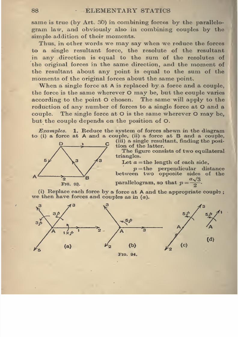
8/4/2019 Elementary Statics of 2 & Dimensions R.J.a. Barnard 1921
http://slidepdf.com/reader/full/elementary-statics-of-2-dimensions-rja-barnard-1921 100/272
88 ELEMENTARY STATICS
same is true (by Art. 30) in combining forces by the parallelo-
gram law, and obviously also in combining couples by the
simple addition of their moments.
Thus, in other words we may say when we reduce the forcesto a single resultant force, the resolute of the resultant
in any direction is equal to the sum of the resolutes of
the original forces in the same direction, and the moment of
the resultant about any point is equal to the sum of the
moments of the original forces about the same point.
When a single force at A is replaced by a force and a couple,
the force is the same wherever O may be, but the couple varies
according to the point O chosen. The same will apply to the
reduction of any number of forces to a single force at O and a
couple. The single force at O is the same wherever O may be,
but the couple depends on the position of O.
Examples. 1. Reduce the system of forces shewn in the diagram
to (i) a force at A and a couple, (ii) a force at B and a couple,
(iii) a single resultant, finding the posi-
tion of the latter.
The figure consists of two equilateral
triangles.
Let a =the length of each side,
p=the perpendicular distance
between two opposite sides of the
parallelogram, so that
p=—^.
(i) Replace each force by a force at A and the appropriate couple;
we then have forces and couples as in (o).
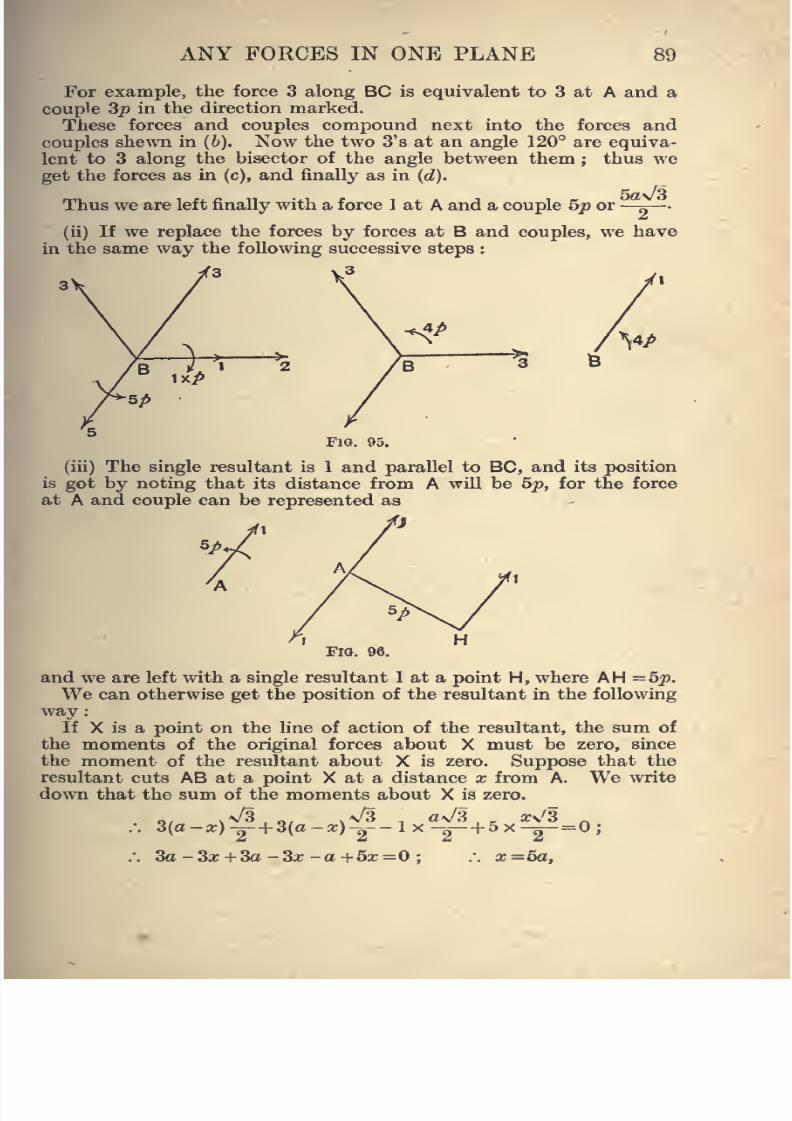
8/4/2019 Elementary Statics of 2 & Dimensions R.J.a. Barnard 1921
http://slidepdf.com/reader/full/elementary-statics-of-2-dimensions-rja-barnard-1921 101/272
ANY FORCES IN ONE PLANE 89
For example, the force 3 along BC is equivalent to 3 at A and a
couple 3^ in the direction marked.
These forces and couples compound next into the forces and
couples shewTi in {b). Now the two 3's at an angle 120° are equiva-
lent to 3 along the bisector of the angle between them ; thus we
get the forces as in (c), and finally as in (d).
5a\/3Thus we are left finally with a force 1 at A and a couple 5p or—^
(ii) If we replace the forces by forces at B and couples, we have
in the same way the following successive steps :
.3
Fig. 95,
(iii) The single resultant is 1 and parallel to BC, and its position
is got by noting that its distance from A will be 5p, for the force
at A and couple can be represented as
Fig. 96.
and we are left with a single resultant 1 at a point H, where AH=5p.We can otherwise get the position of the resultant in the following
way :
If X is a point on the line of action of the resultant, the sum of
the moments of the original forces about X must be zero, since
the moment of the resultant about X is zero. Suppose that the
resultant cuts AB at a point X at a distance x from A. We write
down that the sum of the moments about X is zero.
\/33(a-«)-2-+ 3(a-a;)-2 .^ g
3a -3a; + 3a -3a; -a +6a;=0;
\/3 , a^/3,^ ars'S .
x=5a.
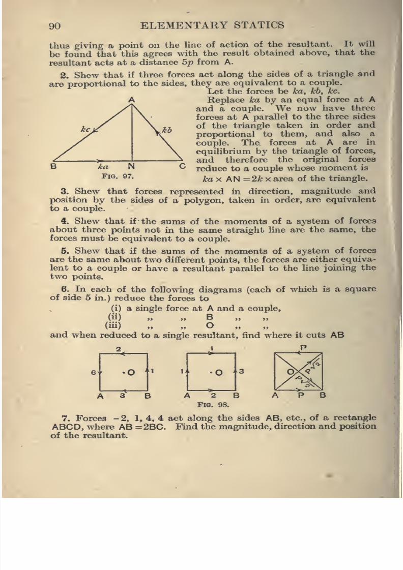
8/4/2019 Elementary Statics of 2 & Dimensions R.J.a. Barnard 1921
http://slidepdf.com/reader/full/elementary-statics-of-2-dimensions-rja-barnard-1921 102/272
90 ELEMENTARY STATICS
thus giving a point on the line of action of the resultant. It will
be found that this agrees with the result obtained above, that the
resultant acts at a distance 5p from A.
2. Shew that if three forces act along the sides of atriangle
andare proportional to the sides, they are equivalent to a couple.
Let the forces be ka, kb, kc.
Replace ka by an equal force at A
and a couple. We now have three
forces at A parallel to the three sides
of the triangle taken in order and
proportional to them, and also a
couple. The forces at A are in
equilibrium by the triangle of forces,
and therefore the original forces
reduce to a couple whose moment is
fci X AN =2ifc X area of the triangle,
3. Shew that forces represented in direction, magnitude and
position by the sides of a polygon, taken in order, are equivalent
to a couple.
4. Shew that if the sums of the moments of a system of forces
about three points not in the same straight line are the same, the
forces must be equivalent to a couple.
5. Shew that if the sums of the moments of a system of forces
are the same about two different points, the forces are either equiva-
lent to a couple or have a resultant parallel to the line joining the
two points.
6. Li each of the following diagrams (each of which is a square
of side 5 in.) reduce the forces to
(i) a single force at A and a couple,
(ii) „ „ B(iii) » „ O
and when reduced to a single resultant, find where it cuts AB
7. Forces -2, 1, 4, 4 act along the sides AB, etc., of a rectangle
ABCD, where AB =2BC. Find the magnitude, direction and position
of the resultant.
8/4/2019 Elementary Statics of 2 & Dimensions R.J.a. Barnard 1921
http://slidepdf.com/reader/full/elementary-statics-of-2-dimensions-rja-barnard-1921 103/272
ANY FORCES IN ONE PLANE 91
8. Forces P, 2P, - P, 2P act along the sides AB, etc., of a square
ABCD, and P->/2 along each of BD and CA. Shew that the forces
reduce to a couple, and find its moment.
67. Conditions for Equilibrium.
We have seen that any system of forces in a plane can be
reduced either to („) ^ single force,
or (fe) a couple,
or (c) zero.
In the latter case the forces are in equilibrium, and it will
be seen (from Art. 65) that for this to occur, the single force
and couple to which the forces were first reduced must be
both zero.
We can now examine the conditions necessary that any
system of forces in a plane may be in equilibrium.
It will be found that when expressed algebraically there are
three conditions necessary for equilibrium, but that the
conditions may be expressed in various alternative ways.
The most usual form is as follows :
A system offorces in a plane is in equilibrium if the sums of
the resolved parts of the forces in any two different directions
are separately zero, and the sum of the moments about one point
is zero.
That these conditions are sufficient to secure equilibrium may
be seen in the following way. By Art. 65 the forces must
reduce either to(^) ^ gj^gl^ fo^^g^
(6) a couple,
(c) nothing at all.
If the above conditions hold we have(1) The forces cannot reduce to a single force, for if the sums
of the resolved parts in any two directions are separately
zero, the resolved part of the resultant would be zero in each
of the two directions, which is impossible.
8/4/2019 Elementary Statics of 2 & Dimensions R.J.a. Barnard 1921
http://slidepdf.com/reader/full/elementary-statics-of-2-dimensions-rja-barnard-1921 104/272
92 ELEMENTARY STATICS
(2) The forces cannot reduce to a couple, for a couple has a
definite moment, not zero, about every point in its plane,
.'. the forces must reduce to nothing at all.
68. Other forms of putting the conditions for equilibrium
are the following :
(1) The sums of the moments about two points A and B
are separately zero, and the sum of the resolved parts in a
direction not perpendicular to AB is zero.
(2) The sums of the moments about three points not in the
same line are separately zero.
We will demonstrate the latter and leave the remaining
case to the student.
If the sum of the moments about A is zero, the forces cannot
reduce to a couple, but may reduce to a single force through A.
Similarly the other conditions give only a possible resultant
through B and through C. But if A, B, C are not in one
straight line the resultant force cannot pass through the three,
and therefore there cannot be a resultant force at all.
69. Solution o! Examples.
In solving examples the method nearly always to be fol-
lowed wiU be to first draw a diagram and mark all the forces,
then write down the three equations obtained by
(i) Equating the sums of the resolved parts in two different
directions to zero separately.
(ii) Equating the sum of the moments about a chosen point
to zero.
From the three equations thus written down the unknown
quantities are to be found, and therefore must not be more thanthree if the question is capable of solution.
In selecting a point O to take moments about, it may be
noticed that if one of the forces passes through O that force
wiU have no moment about O, and therefore will not appear
I
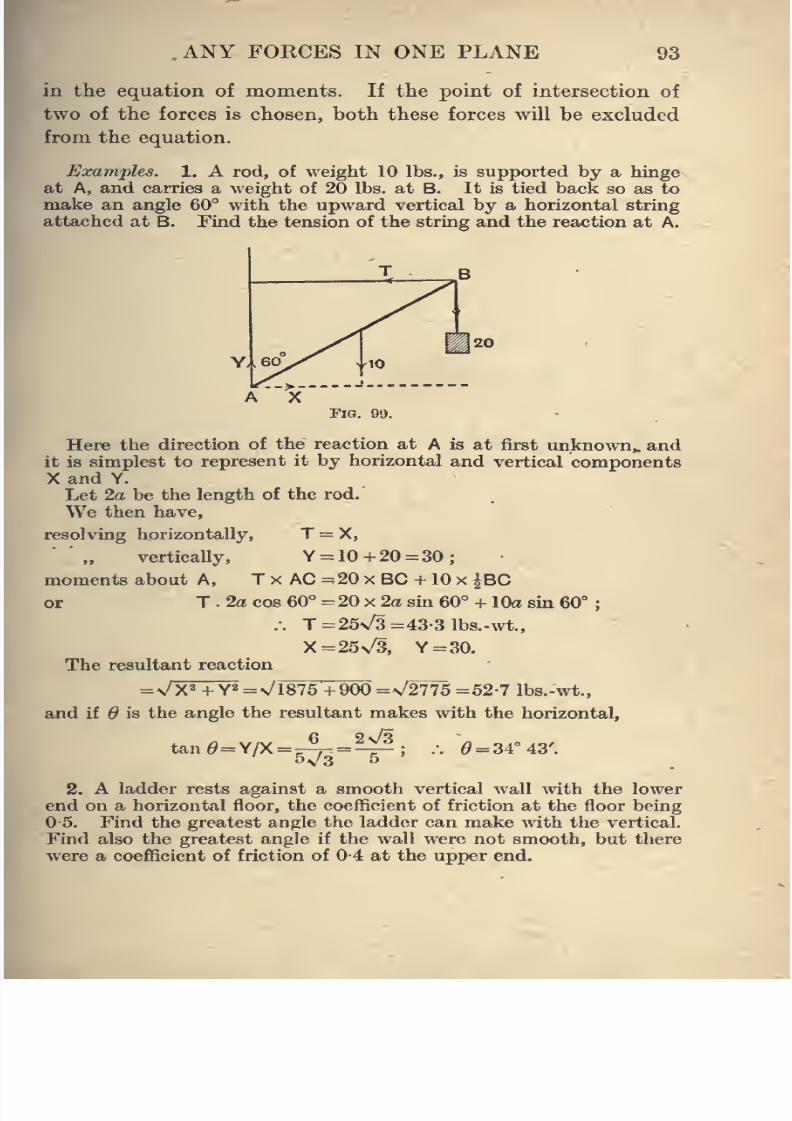
8/4/2019 Elementary Statics of 2 & Dimensions R.J.a. Barnard 1921
http://slidepdf.com/reader/full/elementary-statics-of-2-dimensions-rja-barnard-1921 105/272
ANY FORCES IN ONE PLANE 93
in the equation of moments. If the point of intersection of
two of the forces is chosen, both these forces will be excluded
from the equation.
Examples. 1. A rod, of weight 10 lbs., is supported by a hinge
at A, and carries a weight of 20 lbs. at B. It is tied back so as to
make an angle 60° with the upward vertical by a horizontal string
attached at B. Find the tension of the string and the reaction at A.
Fig. 99.
Here the direction of the reaction at A is at first unkno^vn„ and
it is simplest to represent it by horizontal and vertical componentsX and Y.
Let 2a be the length of the rod.
We then have,
resolving horizontally, T = X,
'„ verticaUy, Y = 10 +20 =30;
moments about A, T x AC =20 x BC + 10 x |BC
or T . 2a cos 60° = 20 x 2a sin 60° + lOo sm 60°
.-. T=25\/3=43-31bs.-wt.,
X=25v/3, Y = 30.
The resultant reaction
=\/X2 + Y2=v/i875+900 =\/2775 =52-7 Ibs.-wt.,
and if 6 is the angle the resultant makes with the horizontal,
, a \,iw 6 2v/3tan^= Y/X =^- =— ^ = 34° 43'.
2. A ladder rests against a smooth vertical wall with the lower
end on a horizontal floor, the coefficient of friction at the floor being
0-5. Find the greatest angle the ladder can make with the vertical.
Find also the greatest angle if the wall were not smooth, but there
were a coefficient of friction of 0-4 at the upper end.
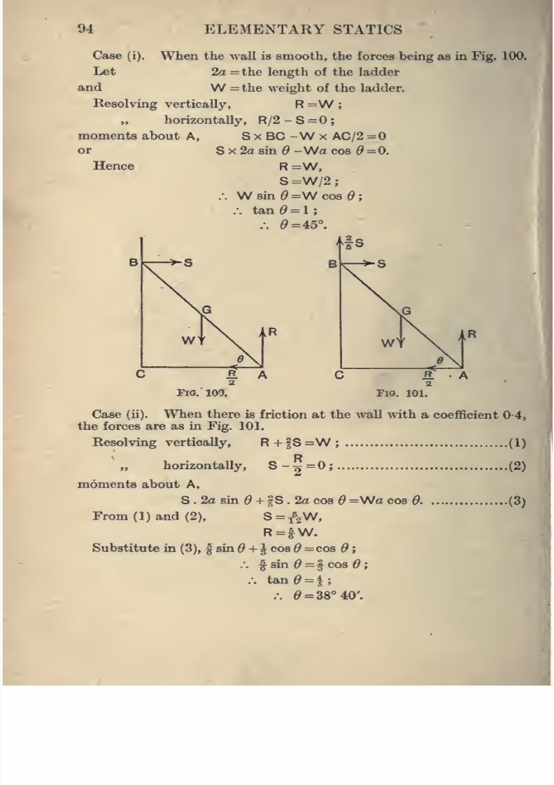
8/4/2019 Elementary Statics of 2 & Dimensions R.J.a. Barnard 1921
http://slidepdf.com/reader/full/elementary-statics-of-2-dimensions-rja-barnard-1921 106/272
94 ELEMENTARY STATICS
Case (i). When the wall is smooth, the forces being as in Fig. 100.
Let 2a =the length of the ladder
and W =the weight of the ladder.
Resolving vertically, R =W;
„ horizontally, R/2 - S =0 ;
moments about A, 8 x BC -W x AC/2 =0
Hence
S X 2a sm ^ -Wa cos 6 =0.
R=W,S =W/2
.-. W an e =\N COB d
:.
tan = 1;.-. 19=45°.
Fig. 100. Fio. 101.
Case (ii). When there is friction at the wall with a coefficient 0-4,
the forces are as in Fig. 101.
Resolving vertically, R+|S=W; (1)
„ horizontally, S-h=0;
moments about A,
S . 2a sm + ?S . 2a cos =Wa cos 9.
From ( 1 ) and (2), S = ^2W,
R=^W.
Substitute in (3), | sin + J cos d cos 6 ;
.". ^sin0=§cos0;
.-. tan = 4;
.-. 0=38° 40'.
.(2)1
(3)1
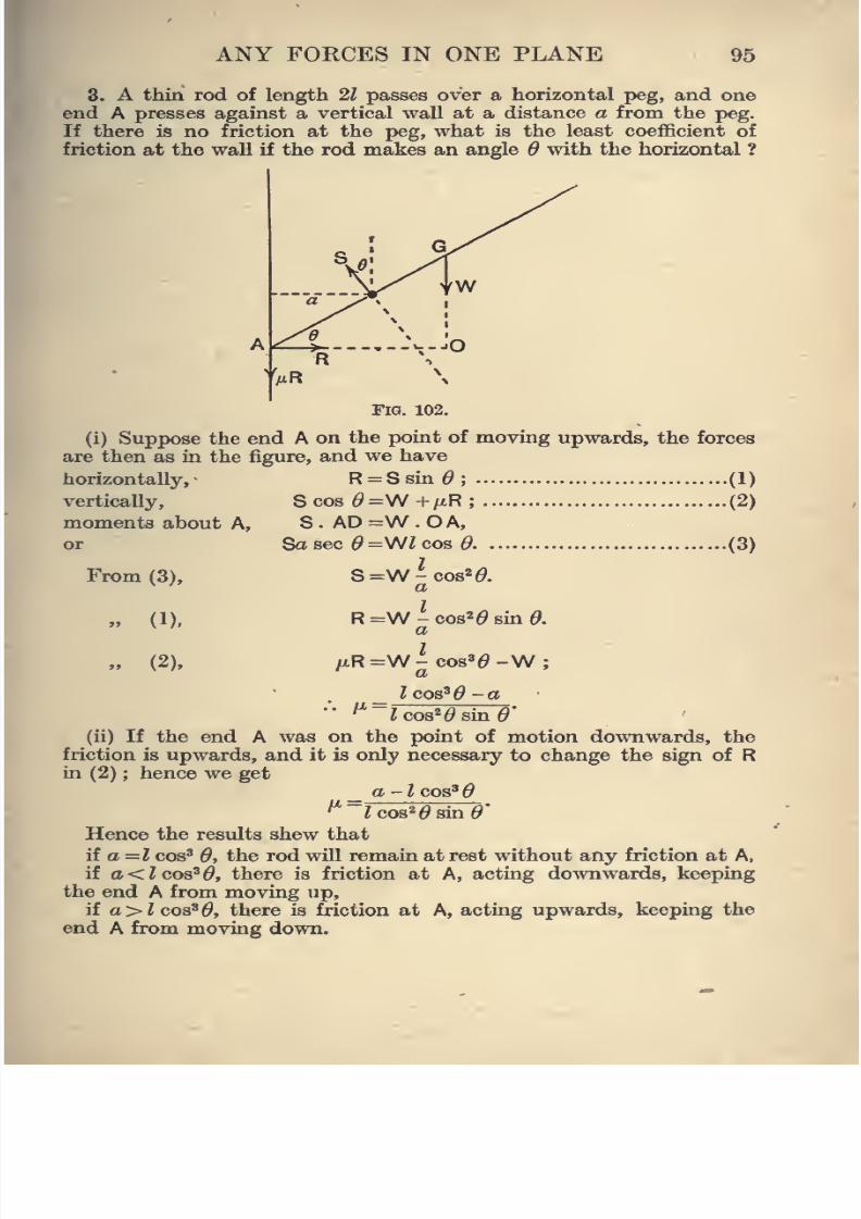
8/4/2019 Elementary Statics of 2 & Dimensions R.J.a. Barnard 1921
http://slidepdf.com/reader/full/elementary-statics-of-2-dimensions-rja-barnard-1921 107/272
ANY FOECES IN ONE PLANE 95
3. A thin rod of length 21 passes over a horizontal peg, and one
end A presses against a vertical wall at a distance a from the peg.
If there is no friction at the peg, what is the least coefficient of
friction at the wall if the rod makes an angle 6 with the horizontal ?
Fig. 102.
(i) Suppose the end A on the point of moving upwards, the forces
are then as in the figure, and we have
horizontally, R = Ssin 6 ; (1)
vertically, S cos d=VJ +fMR; (2)
moments about A, S . AD =W . O A,
From (3),
» (1),
» (2),
Sa sec ^ =WZ cos ^ ,
S=W-cos2^.a
R=W-cos2^sin(9.a
.(3)
aR=W-cos'^^ a W;_ ?COS^^-CT
'^~icos*^sin6»'
(ii) If the end A was on the point of motion downwards, the
friction is upwards, and it is only necessary to change the sign of Rin (2) ; hence we get
_ a -Icoa'd
^~lcoa^daia9'
Hence the results shew thatif a =Z cos' 0, the rod will remain at rest without any friction at A,
if a<Zcos'^, there is friction at A, acting downwards, keeping
the end A from moving up,
if a>Zcos'^, there is friction at A, acting upwards, keeping the
end A from moving down.
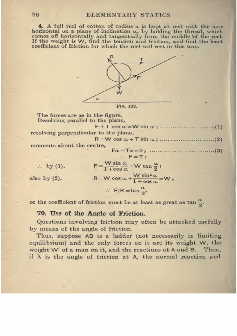
8/4/2019 Elementary Statics of 2 & Dimensions R.J.a. Barnard 1921
http://slidepdf.com/reader/full/elementary-statics-of-2-dimensions-rja-barnard-1921 108/272
96 ELEMENTARY STATICS
4. A full reel of cotton of radius a is kept at re«t mth the axis
horizontal on a plane of inclination a, by holding the thread, whichcomes off horizontally and tangentially from the middle bf the reel.
If the weight is W, find the tension and friction, and find the least
coefficient of friction for which the reel will rest in this way.
Fio. 103.
The forces are as in the figure.
Resolving parallel to the plane,
F + T cos ot.=W sin a. (1)
resolving perpendicular to the plane,
R=Wcosa. + Tsina.; (2)
moments about the centre,
Fa-Ta=0; (3)
.-. F=T;
. u /i\ c Wsina a.,.*. by (1), F=^-; ^Wtan^c;
•' ^'
1 +cosa. 2
also by (2), r =w cos a. +J^^^^^^!^=W ;
1 T COS CC
.-. F/R=tan|,
or the coefficient of friction must be at least as great as tan ^.
70. Use of the Angle ot Friction.
Questions involving friction may often be attacked usefully
by means of the angle of friction.
Thus, suppose AB is a ladder (not necessarily in limiting
equilibrium) and the only forces on it are its weight W, the
weightW of a man on it, and the reactions at A and B. Then,
if X is the angle of friction at A, the normal reaction and
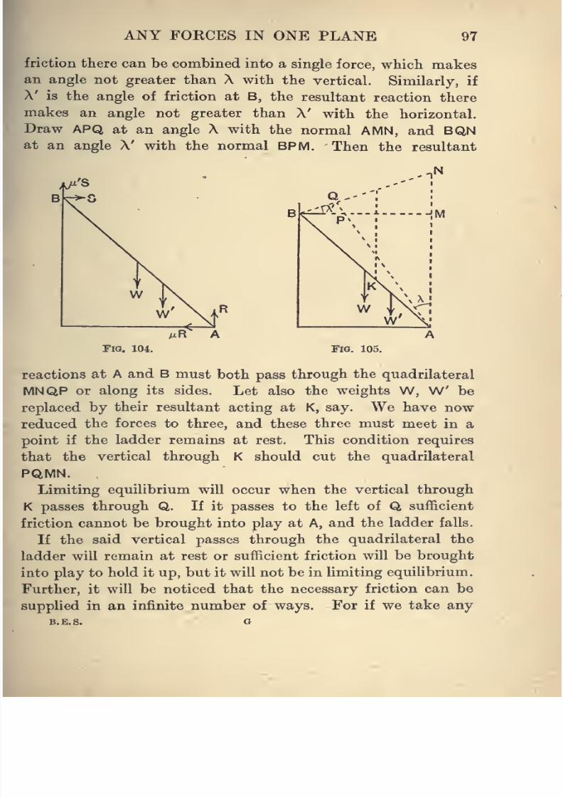
8/4/2019 Elementary Statics of 2 & Dimensions R.J.a. Barnard 1921
http://slidepdf.com/reader/full/elementary-statics-of-2-dimensions-rja-barnard-1921 109/272
ANY FORCES IN ONE PLANE 97
friction there can be combined into a single force, which makes
an angle not greater than X with the vertical. Similarly, if
A' is the angle of friction at B, the resultant reaction there
makes an angle not greater than A' with the horizontal.
Draw APQ at an angle X with the normal AMN, and BQNat an angle X' with the normal BPM. Then the resultant
;|^'S
Fia. 104. Fig. 105.
reactions at A and B must both pass through the quadrilateral
MNQP or along its sides. Let also the weights W, W' be
replaced by their resultant acting at K, say. We have now
reduced the forces to three, and these three must meet in a
point if the ladder remains at rest. This condition requires
that the vertical through K should cut the quadrilateral
PQMN.
Limiting equilibrium will occur when the vertical through
K passes through Q. If it passes to the left of Q sufficient
friction cannot be brought into play at A, and the ladder falls.
If the said vertical passes through the quadrilateral the
ladder will remain at rest or sufficient friction will be brought
into play to hold it up, but it will not be in limiting equilibrium.
Further, it will be noticed that the necessary friction can be
supplied in an infinite number of ways. For if we take any
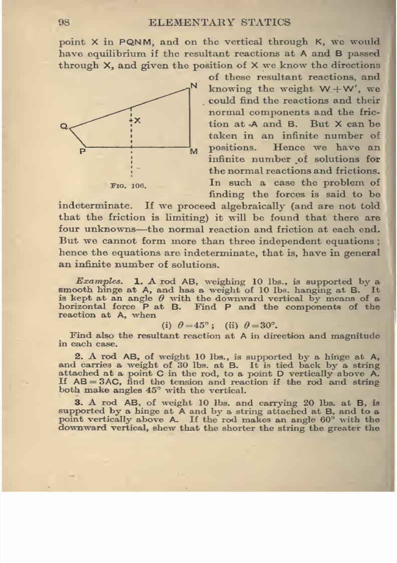
8/4/2019 Elementary Statics of 2 & Dimensions R.J.a. Barnard 1921
http://slidepdf.com/reader/full/elementary-statics-of-2-dimensions-rja-barnard-1921 110/272
98 ELEMENTARY STATICS
FlO. 106.
point X in PQNM, and on the vertical tlirough K, we would
have equilibrium if the resultant reactions at A and B passed
through X, and given the position of X we know the directions
of these resultant reactions, and
knowing the weight W+W, we
could find the reactions and their
normal components and the fric-
tion at -A and B. But X can be
taken in an infinite number of
positions. Hence we have an
infinite number .of solutions for
the normal reactions and frictions.
In such a case the problem of
finding the forces is said to be
indeterminate. If we proceed algebraically (and are not told
that the friction is limiting) it will be found that there are
four unknowns—^the normal reaction and friction at each end.
But we cannot form more than three independent equations
hence the equations are indeterminate, that is, have in general
an infinite number of solutions.
Examples. 1. A rod AB, weighing 10 lbs., is supported by a
smooth hinge at A, and has a weight of 10 lb.s. hanging at B. It
is kept at an angle 6 with the downward vertical by means of a
horizontal force P at B. Find P and the components of thereaction at A, when
(i) (9=45°; (ii) (9=30°.
Find also the resultant reaction at A in direction and magnitude
in each case. J
2. A rod AB, of weight 10 lbs., is supported by a hinge at A,'
and carries a weight of 30 lbs. at B. It is tied back by a string
attached at a point C in the rod, to a point D vertically above A.
If AB = 3AC, find the tension and reaction if the rod and string
both make angles 45° with the vertical.
3. A rod AB, of weight 10 lbs. and carrying 20 lbs. at B, ifl
supported by a hinge at A and by a string attached at B, and to apoint vertically above A. If the rod makes an angle 60° with, the
downward vertical, shew that the shorter the string the greater the
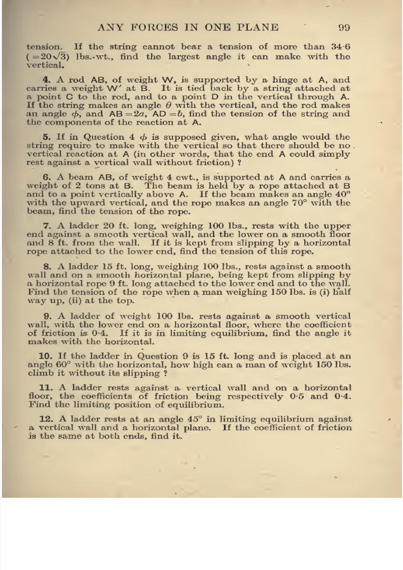
8/4/2019 Elementary Statics of 2 & Dimensions R.J.a. Barnard 1921
http://slidepdf.com/reader/full/elementary-statics-of-2-dimensions-rja-barnard-1921 111/272
ANY FORCES IN ONE PLANE 99
tension. If the string cannot bear a tension of more than 34 6
( =20\/3) Ibs.-wt., find the largest angle it can make with the
vertical.
4. A rod AB, of weight W, is supported by a hinge at A, and
carries a weight W' at B. It is tied back by a string attached at
a point C to the rod, and to a point D in the vertical through A.
If the string makes an angle 6 with the vertical, and the rod makes
an angle </>, and AB =2a, AD =6, find the tension of the string and
the components of the reaction at A.
5. If in Question 4 <jf) is supposed given, what angle would the
string require to make with the vertical so that there should be no
.
vertical reaction at A (in other words, that the end A could simplyrest against a vertical wall without friction) ?
6. A beam AB, of weight 4 cwt., is supported at A and carries a
weight of 2 tons at B. The beam is held by a rope attached at Band to a point vertically above A. If the beam makes an angle 40°
with the upward vertical, and the rope makes an angle 70° with the
beam, find the tension of the rope.
7. A ladder 20 ft. long, weighing 100 lbs., rests with the upper
end against a smooth vertical wall, and the lower on a smooth floor
and 8 ft. from the wall. If it is kept from slipping by a horizontal
rope attached to the lower end, find the tension of this rope.
8. A ladder 15 ft. long, weighing 100 lbs., rests against a smooth
wall and on a smooth horizontal plane, being kept from slipping bya horizontal rope 9 ft. long attached to the lower end and to the wall.
Find the tension of the rope when a man weighing 150 lbs. is (i) h'alf
way up, (ii) at the top.
9. A ladder of weight 100 lbs. rests against a smooth vertical
wall, with the lower end on a horizontal floor, where the coefficient
of friction is 0-4. If it is in limiting equilibrium, find the angle it
makes with the horizontal.
10. If the ladder in Question 9 is 15 ft. long and is placed at an
angle 60° with the horizontal, how high can a man of weight 150 lbs.
climb it without its slipping ?
11. A ladder rests against a vertical wall and on a horizontal
floor, the coefficients of friction being respectively 0-5 and 0-4.
Find the limiting position of equilibrium.
12. A ladder rests at an angle 45° in limiting equilibrium against
a vertical wall and a horizontal plane. If the coefficient of friction
is the same at both ends, find it.
8/4/2019 Elementary Statics of 2 & Dimensions R.J.a. Barnard 1921
http://slidepdf.com/reader/full/elementary-statics-of-2-dimensions-rja-barnard-1921 112/272
100 ELEMENTARY STATICS
13. A ladder rests in limiting equilibrium at an angle 6 with the
horizontal against a vertical wall. If the coefficients of friction at
the upper and lower ends are respectively /x and /x', prove that
tan^ =l^.14. A ladder of weight 100 lbs. rests between a smooth wall and
smooth floor, being prevented from slipping by a rope attached to
the foot of the wall, and to a point in the ladder. If the rope is
perpendicular to the ladder and the ladder makes an angle 60°
with the horizontal, find the tension of the rojjc and the reactions at
the ends.
Find also the tension when a boy weighing 100 lbs. is at the top
of the ladder.
15. A rod of weight 10 lbs. rests with its ends on a smooth hori-
zontal plane and on a smooth plane of inclination 60°. It is kept
at rest at an angle 30° with the horizontal, by a horizontal string
attached to the lower end. Find the tension of the string and the
reactions at the ends of the rod.
16. A rod is in limiting equilibrium, resting horizontally with its
ends on two inclined planes at right angles, one of which makesan angle a. ( <45°) with the horizontal. If the coefficient of friction
fi is the same at both ends, prove that
cos a. - sin a.
M = : »
cosoL+smoL
and that A =45° -a..
17. If in Question 16 the steeper plane is smooth and the rod
reata as before, prove that/i =cot 2a.,
A =90° -2a..
18. A weightless rod of length I is placed between two roughvertical posts at a distance d apart less than I. If /x is the coefficient
of friction, what is the lowest point of the rod at which a weight
can be hung without the rod slipping down ?
19. An equilateral triangle is formed by three uniform rods
rigidly attached to one another at their ends, and is suspended on
a rough horizontal peg, the angle of friction between peg and rods
being A. Find the range of possible equilibrium positions, excluding
those in which the peg is at a vertex of the triangle.
20. A cotton reel, partly emptied, rests on a rough plane inclined
at an angle a. to the horizontal. The end of the thread is held so
that it comes off parallel to the plane. If the radius of the reel
is a and the radius of the cylinder formed by the cotton is h, find
the least coefficient of friction necessary to prevent it from sliding
down.
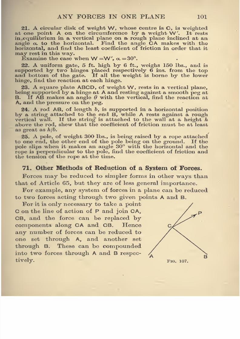
8/4/2019 Elementary Statics of 2 & Dimensions R.J.a. Barnard 1921
http://slidepdf.com/reader/full/elementary-statics-of-2-dimensions-rja-barnard-1921 113/272
ANY FORCES IN ONE PLANE 101
21. A circular disk of weight W, whose centre is C, ia weighted
at one point A on the circumference by a weight W'. It rests
in,equilibrium in a vertical plane on a rough plane inclined at an
angle a. to the horizontal. Find the angle CA makes with the
horizontal, and find the least coefficient of friction in order that it
may rest in this way.
Examine the case whenW =W', a. = 30°.
22. A uniform gate, 5 ft. high by 6 ft., weighs 150 lbs., and is
supported by two hinges placed respectively 6 ins. from the top
and bottom of the gate. If all the weight is borne by the lower
hinge, find the reaction at each hinge.
23. A square plate ABCD, of weight W, rests in a vertical plane,
being supported by a hinge at A and resting against a smooth peg atB. If AB makes an angle 6 with the vertical, find the reaction at
A, and the pressure on the peg.
24. A rod AB, of length h, is supported in a horizontal position
by a string attached to the end B, while A rests against a rough
vertical wall. If the string is attached to the wall at a height h
above the rod, shew that the coefficient of friction must be at least
as great as hjh,
25. A pole, of weight 300 lbs., is being raised by a rope attached
to one end, the other end of the pole being on the ground. If the
pole slips when it makes an angle 30° with the horizontal and the
rope is perpendicular to the pole, find the coefficient of friction and
the tension of the rope at the time.
71. Other Methods of Reduction of a System of Forces.
Forces may be reduced to simpler forms in other ways than
that of Article 65, but they are of less general importance.
For example, any system of forces in a plane can be reduced
to two forces acting through two given points A and B.
For it is only necessary to take a point
C on the line of action of P and join CA,
CB, and the force can be replaced by
components along CA and CB. Hence
any number of forces can be reduced to
one set through A, and another set
through B. These can be compounded
into two forces through A and B respec-
tively. Fio. 107.
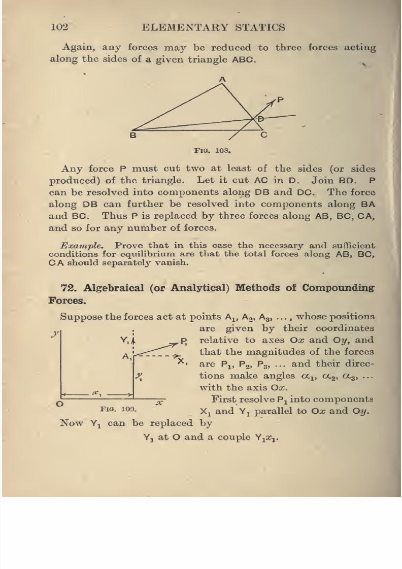
8/4/2019 Elementary Statics of 2 & Dimensions R.J.a. Barnard 1921
http://slidepdf.com/reader/full/elementary-statics-of-2-dimensions-rja-barnard-1921 114/272
102 ELEMENTARY STATICS
Again, any forces may be reduced to tliree forces acting
along the sides of a given triangle ABC.
Fig. 108.
Any force P must cut two at least of the sides (or sides
produced) of the triangle. Let it cut AC in D. Join BD. P
can be resolved into components along DB and DC. The force
along DB can further be resolved into components along BA
and BC. Thus P is replaced by three forces along AB, BC, CA,
and so for any number of forces.
Example. Prove that in this case the necessary and sufficient
conditions for equilibrium are that the total forces along AB, BC,
CA should separately vanish.
72. Algebraical (or Analytical) Methods of Compounding
Forces.
y
Suppose the forces act at points A^, Ag, A3, . .., whose positions
are given by their coordinates
YiA _^p relative to axes Ox and Oy, and
that the magnitudes of the forces
^' are Pj, Pg, P3, ... and their direc-
^^ tions make angles a^, ag, 0C3, ...
with the axis Ox.^ First resolve P^ into components
FIG. 109.Xi and Yj parallel to Ox and O^.
Now YjL can be replaced by
Vj at O and a couple ViX^.
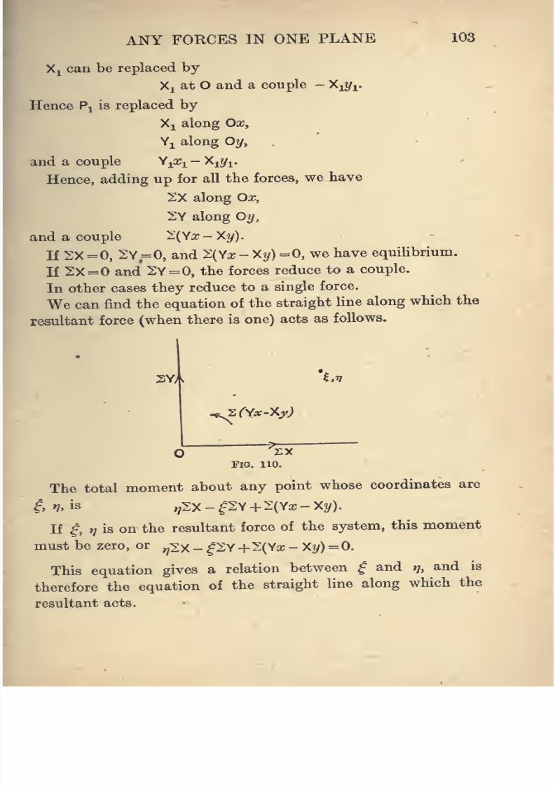
8/4/2019 Elementary Statics of 2 & Dimensions R.J.a. Barnard 1921
http://slidepdf.com/reader/full/elementary-statics-of-2-dimensions-rja-barnard-1921 115/272
ANY FORCES IN ONE PLANE 103
Xj can be replaced by
Xi at O and a couple - Xi^/i.
Hence P^ is replaced by
Xj along Ox,
Yi along Oy,
and a couple Y^x^ - Xi?/i.
Hence, adding up for all the forces, we have
2X along Ox,
2Y along Oy,
and a couple 2{yx-Xy).
If 2X =0, 2Y =0, and 2(Ya; - X^) =0, we have equilibrium.
If 2X=0 and 2Y = 0, the forces reduce to a couple.
In other cases they reduce to a single force.
We can find the equation of the straight line along which the
resultant force (when there is one) acts asfollows.
2Y, Xv
-Nsrv^-xj^;
Fig. 110.
The total moment about any point whose coordinates are
i, n, is ,;2X - ^2Y +2(Ya; - X?/).
If ^, t] is on the resultant force of the system, this moment
must be zero, or ^v^ _ ^2Y +2(Ya; - X^/) =0.
This equation gives a relation between ^ and i/, and is
therefore the equation of the straight line along which the
resultant acts.
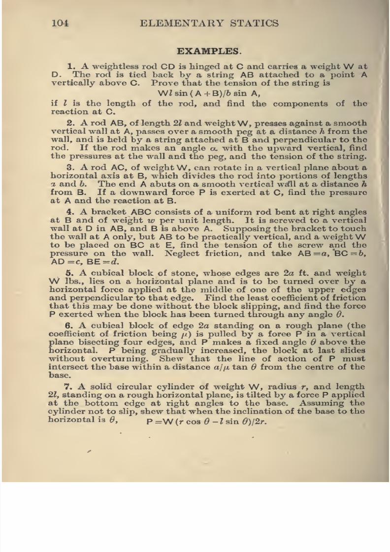
8/4/2019 Elementary Statics of 2 & Dimensions R.J.a. Barnard 1921
http://slidepdf.com/reader/full/elementary-statics-of-2-dimensions-rja-barnard-1921 116/272
104 ELEMENTARY STATICS
EXAMPLES.
1. A weightless rod CD is hinged at C and carries a weightW at
D. The rod is tied back by a string AB attached to a point Avertically above C. Prove that the tension of the string is
WZBin(A + B)/6 8in A,
if I is the length of the rod, and find the components of the
reaction at C.
2. A rod AB, of length 21 and weight W, presses against a smooth
vertical wall at A, passes over a smooth peg at a distance h from the
wall, and is held by a string attached at B and perpendicular to the
rod. Ifthe rod makes an angle a. with the upward vertical, find
the pressures at the wall and the peg, and the tension of the string.
8. A rod AC, of weight W, can rotate in a vertical plane about a
horizontal axis at B, which divides the rod into portions of lengths
a and b. The end A abuts on a smooth vertical w^fll at a distance h
from B. If a downward force P is exerted at C, find the pressure
at A and the reaction at B.
4. A bracket ABC consists of a uniform rod bent at right angles
at B and of weight w per unit length. It is screwed to a vertical
wall at D in AB, and B is above A. Supposing the bracket to touchthe wall at A only, but AB to be practically vertical, and a weightWto be placed on BC at E, find the tension of the screw and the
pressure on the wall. Neglect friction, and take AB=a,'BC=b,AD=c, BE=d.
5. A cubical block of stone, whose edges are 2a ft. and weight
W lbs., lies on a horizontal plane and is to be turned over by a
horizontal force applied at the middle of one of the upper edges
and perpendicular to that edge. Find the least coefficient of friction
that this may be done without the block slipping, and find the force
P exerted when the block has been turned through any angle 6.
6. A cubical block of edge 2a standing on a rough plane (the
coefficient of friction being /i) is pulled by a force P in a vertical
plane bisecting four edges, and P makes a fixed angle above the
horizontal. P being gradually increased, the block at last slides
without overturning. Shew that the line of action of P must
intersect the base within a distance ajfj. tan from the centre of the
base.
7. A soUd circular cylinder of weight W, radius r, and length
21, standing on a rough horizontal plane, is tilted by a force P applied
at the bottom edge at right angles to the base. Assuming the
cylinder not to slip, shew that when the inclination of the base to the
horizontal is 6, p ^w (r cos 6 -I sin e)l2r.
8/4/2019 Elementary Statics of 2 & Dimensions R.J.a. Barnard 1921
http://slidepdf.com/reader/full/elementary-statics-of-2-dimensions-rja-barnard-1921 117/272
ANY FORCES IN ONE PLANE 105
8. A sphere is resting on a rough horizontal plane. A pressure
P is applied at a point the radius to which makes an angle a. with
the vertical. If equilibrium still subsists, find the direction of P,
and shew that P cannot be greater than
juW/fsia.
sm-2-/"^°«2
if tan ^ is greater than /x.
9. A rectangular board ABCD, of weight W, rests with its plane
vertical and the side AB below DC, these sides making an angle a.
with the horizontal, and is supported by a rough peg at the middle
point of
ABand with the side
CDpressing against a smooth peg P.
Find the reactions at the pegs, and if the angle of friction (A) is
less than a, prove that the distance of P from the middle point of
CD cannot be greater than BC sin a. sin A/2 sin (a. - A).
10. A square plate of edge 2a stands in a vertical plane with two
sides horizontal, the lower of which rests on a rough peg at a distance
d from a rough vertical wall against which an upper corner of the
plate presses, the vertical side through this corner being otherwise
just clear of the wall. Shew that if the coefficients of friction are
the same at the two contacts, they cannot be less than V
11. A rod AB rests with one end on a rough horizontal plane,
and passes over a smooth peg at a height h above the plane. Shewthat if the rod makes an angle d with the horizontal, the least
coefficient of friction is I sin^^ cos 6l{h - Z sin ^ cos*^) if the length
of the rod is 21.
12. A drawer, of breadth 2a and depth (from front to back) 26,has two symmetrically placed handles 2d apart. Shew that (neglect-
ing the weight of the drawer) the drawer cannot be pulled out by one
handle if the coefficient of friction between the drawer and its guides
is greater than hid.
13. A rectangular window frame, ,3 ft. wide and 2 ft. 6 ins. high,
Wand of weight W, is counterpoised by weights, each -— , attached
to cords passing over pulleys and attached to the upper corners of
the frame. What is the least coefficient of friction necessary that
if one cord breaks the frame may not fall ?
14. A vertical cylindrical bar, of weight W, can slide in two fixed
horizontal rings A, B, of slightly greater diameter, at a distance d
apart. The bar is to be raised slowly by a vertical force P at a
8/4/2019 Elementary Statics of 2 & Dimensions R.J.a. Barnard 1921
http://slidepdf.com/reader/full/elementary-statics-of-2-dimensions-rja-barnard-1921 118/272
106 ELEMENTARY STATICS
distance c from the axis of the cylinder. Assuming a coefficient of
friction /x at the contact with each ring, prove that
-w/(.-?r).
Explain what happens if 2//c>rf.
15. A ladder of length 21 is in contact with a vertical wall and a
horizontal floor, the angle of friction being X. at each contact. If
the weight of the ladder acts at a distance hi from the middle point
downwards, prove that the limiting inclination 9 to the vertical is
cot~^(cot 2X. -k cosec 2A).
If the coefficient of friction isJ,
prove that the ladder will
slip at any angle if the centre of mass is more than one-tenth of thelength from the lower end.
16. A gasalier with two straight arms, each of length a in a line at
right angles to the descending tube of length I, is hanging out of
plumb from the joint at the top. A horizontal force P, applied at
the lower end of the descending tube, brings the gasalier plumb.
Find the weight at the end of the arm that would do so.
17. A plate can turn in its plane, which is horizontal about an
axis O. A cord passes round two smooth pegs in the same line as O,
and the ends are attached to two fixed points A and B outside the
plate and in the same plane as it. The strings run from A and Bperpendicular to AB. AB=a, B0=&^ A couple L is applied to the
plate so as to strain the string. Find its tension.
18. A ladder weighing 200 lbs. rests at an angle 65° with the hori-
zontal. If the friction at the lower end is 40 Ibs.-wt., find the
normal reaction there and the friction and normal reaction at the
upper end.
19. A rectangular box is tilted up so that the two long bottom
edges rest one against a smooth vertical wall, and the other on a
rough horizontal floor, and the bottom makes an angle f^ with the
vertical. If the breadth and height are 26 and 2h respectively, shew
that it is on the point of slipping if tan a. =2/i -h-r-
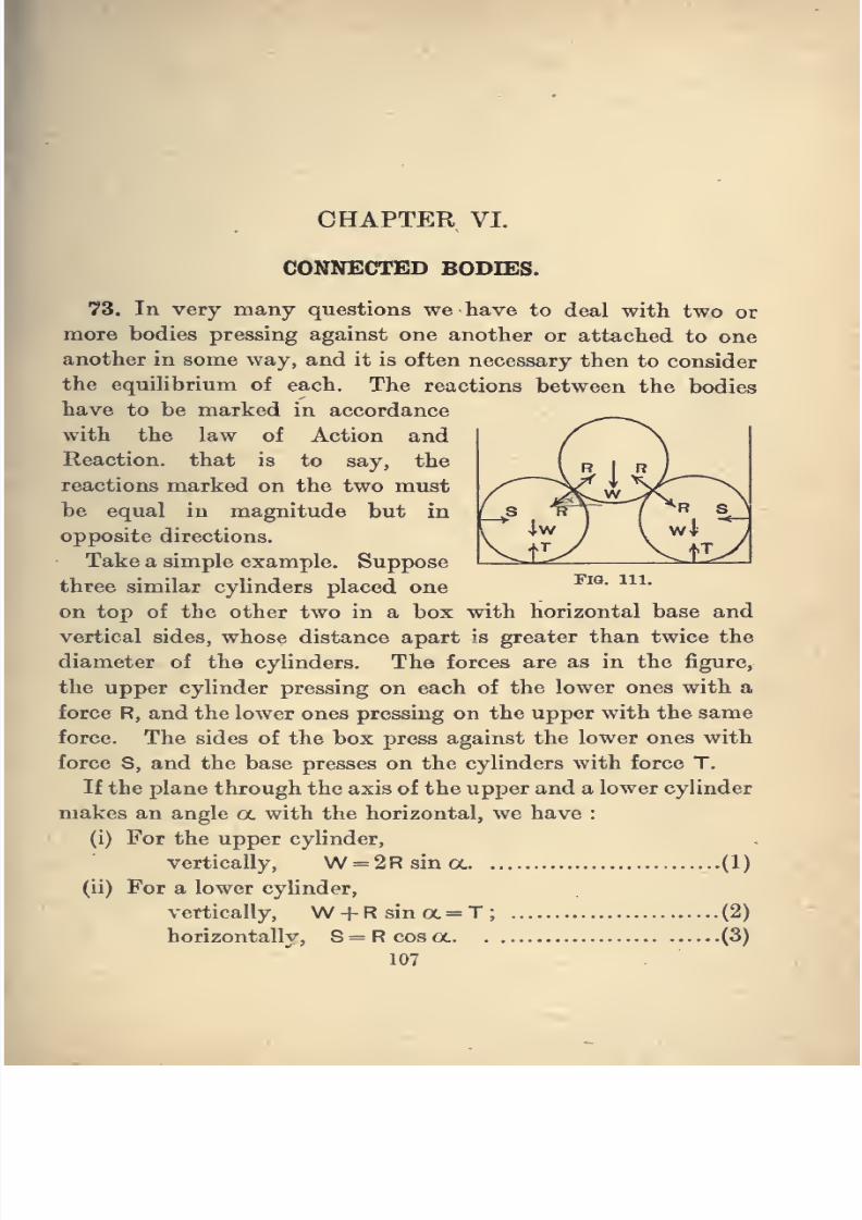
8/4/2019 Elementary Statics of 2 & Dimensions R.J.a. Barnard 1921
http://slidepdf.com/reader/full/elementary-statics-of-2-dimensions-rja-barnard-1921 119/272
CHAPTER VI.
CONNECTED BODIES.
Fia. 111.
73. In very many questions we have to deal with two or
more bodies pressing against one another or attached to one
another in some way, and it is often necessary then to consider
the equilibrium of each. The reactions between the bodies
have to be marked in accordance
with the law of Action and
Reaction, that is to say, the
reactions marked on the two must
be equal in magnitude but in
opposite directions.
Take a simple example. Suppose
three similar cylinders placed one
on top of the other two in a box with horizontal base and
vertical sides, whose distance apart is greater than twice the
diameter ofthe cylinders. The
forces are as in the figure,
the upper cylinder pressing on each of the lower ones with a
force R, and the lower ones pressing on the upper with the same
force. The sides of the box press against the lower ones with
force S, and the base presses on the cylinders with force T.
If the plane through the axis of the upper and a lower cylinder
makes an angle a. with the horizontal, we have :
(i) For the upper cylinder,
vertically, W = 2Rsina. (1)
(ii) For a lower cylinder,
vertically, W + Rsina= T; (2)
horizontally, S=Rcosa. (3)
107
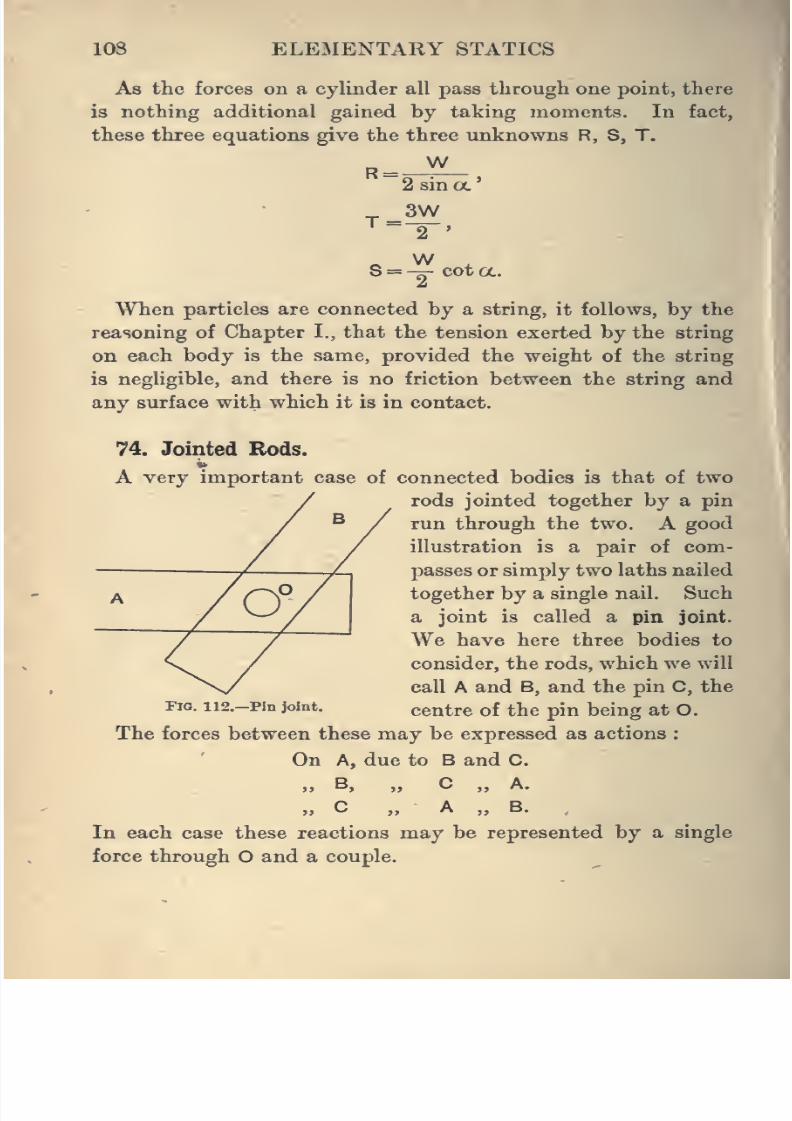
8/4/2019 Elementary Statics of 2 & Dimensions R.J.a. Barnard 1921
http://slidepdf.com/reader/full/elementary-statics-of-2-dimensions-rja-barnard-1921 120/272
108 ELEMENTARY STATICS
As the forces on a cylinder all pass through one point, there
is nothing additional gained by taking moments. In fact,
these three equations give the three unknowns R, S, T.
WR =
T =
2 sin a.
3W2 '
WS = -^ cot a.
When particles are connected by a string, it follows, by the
reasoning of Chapter I., that the tension exerted by the string
on each body is the same, provided the weight of the string
is negligible, and there is no friction between the string and
any surface with which it is in contact.
74. Jointed Rods.
A very important case of connected bodies is that of two
rods jointed together by a pin
run through the two. A good
illustration is a pair of com-
passes or simply two laths nailed
together by a single nail. Such
a joint is called a pin joint.
We have here three bodies to
consider, the rods, which we will
call A and B, and the pin C, the
Fio. ii2.-Pm joint. centre of the pin being at O.
The forces between these may be expressed as actions :
On A, due to B and C.
j> B, „ C „ A.
» C „ A „ B.,
In each case these reactions may be represented by a single
force through O and a couple.
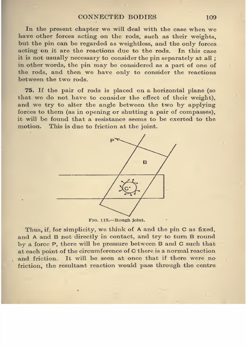
8/4/2019 Elementary Statics of 2 & Dimensions R.J.a. Barnard 1921
http://slidepdf.com/reader/full/elementary-statics-of-2-dimensions-rja-barnard-1921 121/272
CONNECTED BODIES 109
In the present chapter we will deal with the case when we
have other forces acting on the rods, such as their weights,
but the pin can be regarded as weightless, and the only forces
acting on it are the reactions due to the rods. In this case
it is not usually necessary to consider the pin separately at all
in other words, the pin may be considered as a part of one of
the rods, and then we have only to consider the reactions
between the two rods.
75. If the pair of rods is placed on a horizontal plane (so
that we do not have to consider the effect of their weight),
and we try to alter the angle between the two by applying
forces to them (as in opening or shutting a pair of compasses),
it will be found that a resistance seems to be exerted to the
motion. This is due to friction at the joint.
Fia. 113.—Rough joint.
Thus, if, for simplicity, we think of A and the pin C as fixed,
and A and B notdirectly in contact, and try to turn B round
by a force P, there will be pressure between B and C such that
at each point of the circumference of C there is a normal reaction
and friction. It will be seen at once that if there were no
friction, the resultant reaction would pass through the centre
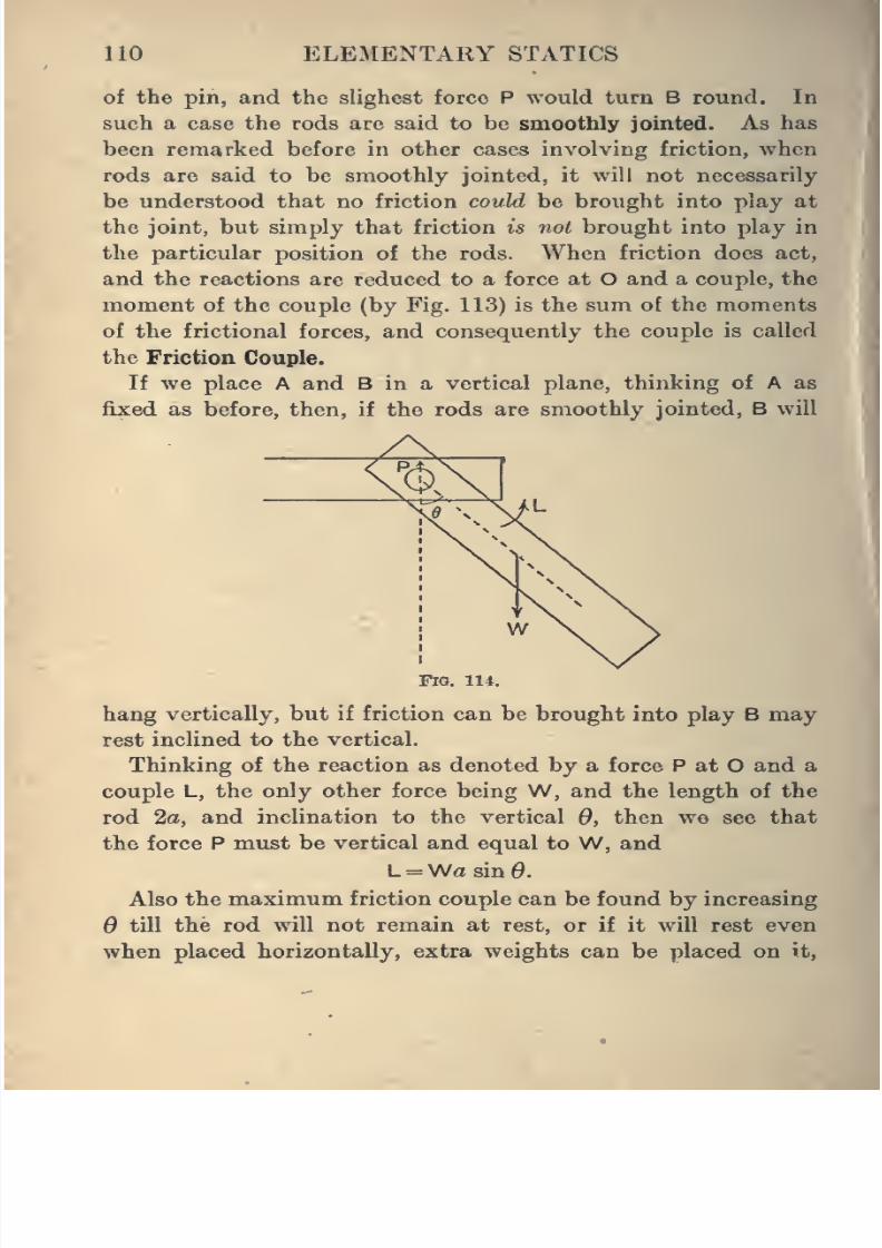
8/4/2019 Elementary Statics of 2 & Dimensions R.J.a. Barnard 1921
http://slidepdf.com/reader/full/elementary-statics-of-2-dimensions-rja-barnard-1921 122/272
no ELEMENTARY STATICS
of the pin, and the slighest force P would turn B round. In
such a case the rods are said to be smoothly jointed. As has
been remarked before in other cases involving friction, when
rods are said to be smoothly jointed, it will not necessarily
be understood that no friction could be brought into play at
the joint, but simply that friction is not brought into play in
the particular position of the rods. When friction does act,
and the reactions are reduced to a force at O and a couple, the
moment of the couple (by Fig. 113) is the sum of the moments
of the frictional forces, and consequently the couple is called
the Friction Couple.
If we place A and B in a vertical plane, thinking of A as
fixed as before, then, if the rods are smoothly jointed, B will
Fig. 114.
hang vertically, but if friction can be brought into play B may
rest inclined to the vertical.
Thinking of the reaction as denoted by a force P at O and a
couple L, the only other force being W, and the length of the
rod 2a, and inclination to the vertical 6, then we see that
the force P must be vertical and equal to W, and
L = Wasin0.
Also the maximum friction couple can be found by increasing
6 till the rod will not remain at rest, or if it will rest even
when placed horizontally, extra weights can be placed on it.
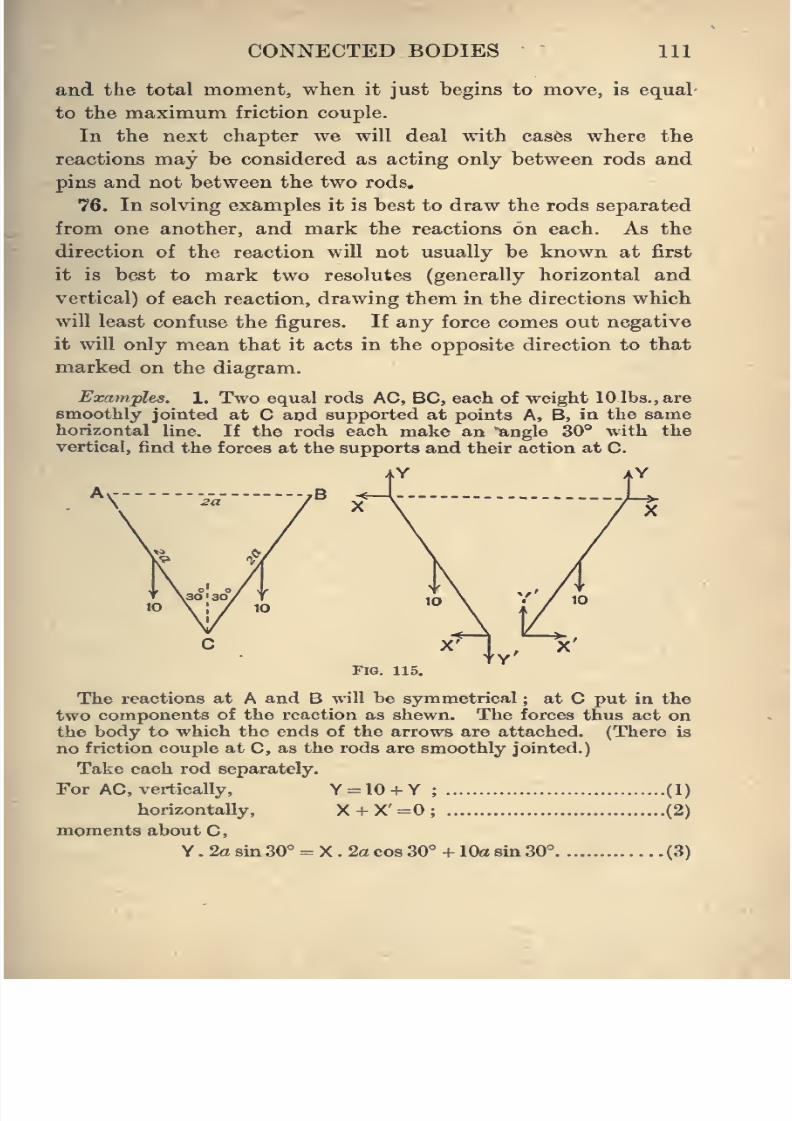
8/4/2019 Elementary Statics of 2 & Dimensions R.J.a. Barnard 1921
http://slidepdf.com/reader/full/elementary-statics-of-2-dimensions-rja-barnard-1921 123/272
CONNECTED BODIES 111
and the total moment, when it just begins to move, is equal
to the maximum friction couple.
In the next chapter we will deal with cases where the
reactions may be considered as acting only between rods and
pins and not between the two rods,
76. In solving examples it is best to draw the rods separated
from one another, and mark the reactions on each. As the
direction of the reaction will not usually be known at first
it is best to mark two resolutes (generally horizontal and
vertical) of each reaction, drawingthem
in the directions which
will least confuse the figures. If any force comes out negative
it will only mean that it acts in the opposite direction to that
marked on the diagram.
Examples. 1. Two equal rods AC, BC, each of weight 10 lbs., are
smoothly jointed at C and supported at points A, B, in the samehorizontal line. If the rods each make an "angle 30° with the
vertical, find the forces at the supports and their action at C.
C X' I X'
Fig. 115.
The reactions at A and B will be symmetrical ; at C put in the
two components of the reaction as shewn. The forces thus act on
the body to which the ends of the arrows are attached. (There is
no friction couple at C, as the rods are smoothly jointed.)
Take each rod separately.
For AC, vertically, Y-IO + Y ; (I)
horizontally, X + X'=0; (2)
moments about C,
Y . 2a 8m30° = X . 2a cos 30° + 10a sin 30° (3)
8/4/2019 Elementary Statics of 2 & Dimensions R.J.a. Barnard 1921
http://slidepdf.com/reader/full/elementary-statics-of-2-dimensions-rja-barnard-1921 124/272
112 ELEMENTARY STATICS
For BC, verticaUy, Y + Y' = 10. (4)
The other equations for BC are the same as for AC.
Hence we have four equations for four unknowns.
From (1) and (4) we getY'=0, Y = 10,
and (3) then gives X . 2o 1^ = 10a xJ,
X=5/N/3=2-891b8.-wt.,
X'= -2-89 lb3.-wt.
We can now write down the resultant force at A as we have the
two components. Its magnitude la
V^+ 100 = 10-41, and its
direction makes an angle with the vertical equal to tan~* 2v^3 or
73° 54'.
The reaction at C is horizontal and acts in the opposite direction
to that drawn in the figure ; in other words, the rod AC pulls at BC,
and BC pulls at AC, as is obvious must be the case.
77. Frequently considerations of . symmetry shorten the
work. In the present example we used it in marking the forces
at A and B as the same. But if we look further into the
matter we will find that we could have said from the first that
the reaction at C is horizontal. For Newton's Law of Action
and Reaction requires that the vertical components on the
two rods should be in opposite directions, as shewn in the
figure, but symmetry requires that these components should
be in the same direction ; these two requirements can only
be satisfied by the vertical components being zero. We can
therefore leave out Y' in the diagram, and we have only three
unknowns and only have to use the equations for one rod.
It is always possible to write down three equations for each
rod. We ought then to have the correct number of equations
to find the unknowns, and can solve algebraically. But this
process may be awkward, and it is frequently possible to forman equation containing one of the unknowns only, and so find
it and continue with other equations, selecting them so that
each, new equation contains one new unknown. In doing this
it is frequently advantageous to form equations for two or
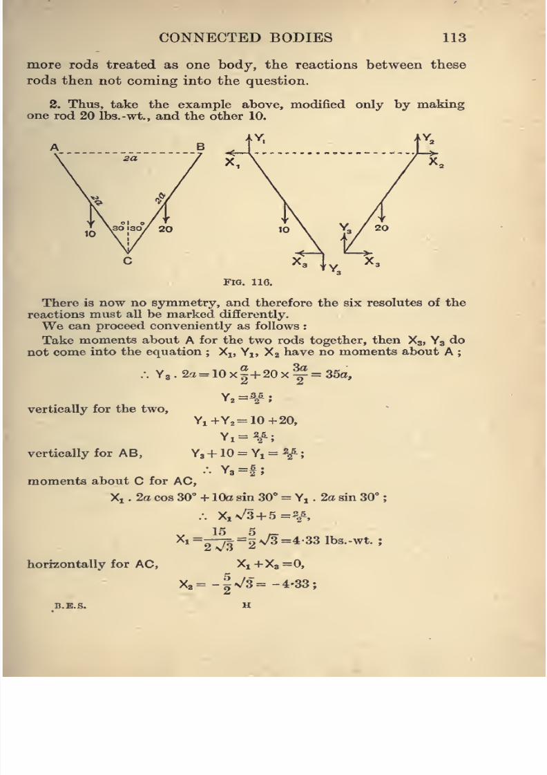
8/4/2019 Elementary Statics of 2 & Dimensions R.J.a. Barnard 1921
http://slidepdf.com/reader/full/elementary-statics-of-2-dimensions-rja-barnard-1921 125/272
CONNECTED BODIES 113
more rods treated as one body, the reactions between these
rods then not coming into the question.
2. Thus, take the example above, modified only by makingone rod 20 Ibs.-wt., and the other 10.
Fig. 116.
There is now no symmetry, and therefore the six resolutes of the
reactions must aU be markeddifferently.
We can proceed conveniently as follows :
Take moments about A for the two rods together, then Xg, Y3 do
not come into the equation ; Xj, Yj, X2 have no moments about A ;
.-. Y2.2a= 10x|+20xy=35a,
vertically for the two,
Yi+Y2= 10+20,
Yi=^;
vertically for A B, Y3+ 10 = Yj = ^:. Y8=f
moments about C for AC,
Xi . 2a cos 30° + 10a sin 30° = Y, . 2a sin 30°
.-. XiV3 + 5=2/,
15 5 ^Xi=—^=2V3=4-33 Ibs.-wt. ;
horizontally for AC, Xi+X8=0,
X3--|\/3"=-4-33;
B.E.S. H
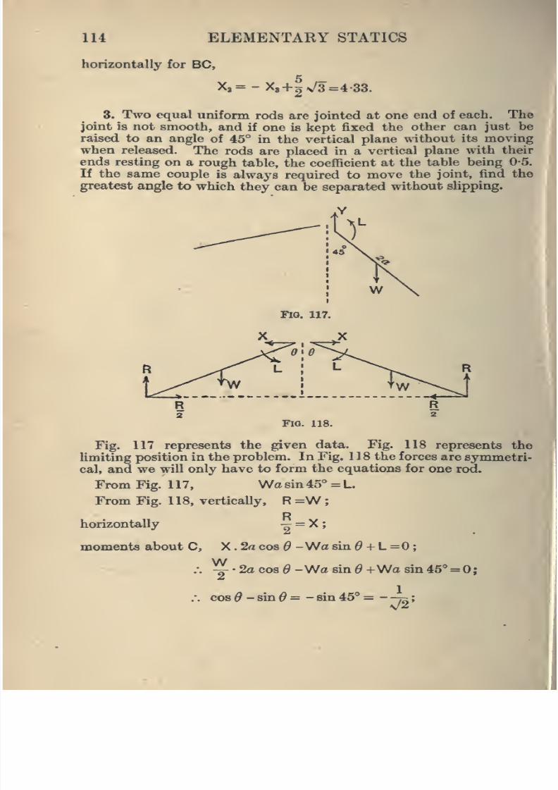
8/4/2019 Elementary Statics of 2 & Dimensions R.J.a. Barnard 1921
http://slidepdf.com/reader/full/elementary-statics-of-2-dimensions-rja-barnard-1921 126/272
114 ELEMENTARY STATICS
horizontally for BC,
X,= -XB+gv/3=4-33.
3. Two equal uniform rods are jointed at one end of each. Thejoint is not smooth, and if one is kept fixed the other can just be
raised to an angle of 45° in the vertical plane without its moving
when released. The rods are placed in a vertical plane with their
ends resting on a rough table, the coefficient at the table being 0-5.
If the same couple is always required to move the joint, find the
greatest angle to which they can be separated without sUpping.
Fig. 117.
no. 118.
Fig. 117 represents the given data. Fig. 118 represents the
limiting position in the problem. In Fig. 118 the forces are symmetri-
cal, and we will only have to form the equations for one rod.
From Fig. 117, \Na sin 45° = L.
From Fig. 118, vertically, R =Wp
horizontally "9 ~ ^ '
moments about C, X.2aco8^ -Wo8in^ + L=0;
W^ • 2a cos ^ -Wo sin d +Wa sin 46'=0;
1
cos $-and= -sia 45° = -
v/2'
8/4/2019 Elementary Statics of 2 & Dimensions R.J.a. Barnard 1921
http://slidepdf.com/reader/full/elementary-statics-of-2-dimensions-rja-barnard-1921 127/272
CONNECTED BODIES 115
a'^ • ^ 1 1
\/2 v/2 2
.-. cos(^+45°)=cosl20°;
.-. ^+45° = 120°;
.-. ^=75°.
4. Two rods, AB, BC, are jointed at B, and attached to fixed
points A, C in the same vertical, A being above C. If BC is hori-
zontal, and AB makes an angle 30° with the vertical, and the weights
are 20 lbs. and 10 lbs. respectively, find the reactions at A, B, and C,
5. Solve the same question as No. 4, except that BC makes an
angle 60''
with the vertical.
6. AB, BC are two rods jointed at B, and of lengths 3 ft. and
4 ft., and weights 15 and 20 lbs., supported at two points A and Cin the same horizontal line. If AC =5 ft., find the reactions at
A, B, and C.
7. Solve the same question as No. 6, except that AC is vertical
with A above B.
8. Three rods, AB, BC, CD, of equal weight and equal length 2a,
are smoothly hinged at B and C and supported at points A and Din the same horizontal line. If AB and CD make angles a with
the horizontal, find the reactions at A and B.
9. Three equal rods, as in Question 8, are supported at points
A and D not in the same horizontal. If a, (i, y are the angles the
rods make with the horizontal, prove that tan a, tan (i, tan y are
in A.P., and find the components of the reactions at A, B, C, D.
10. Three rods, AB, BC, CD, of lengths 2a, 26, 2a, but of equal
weight, smoothly hinged at B and C, rest symmetrically in a vertical
plane with AB, CD, on two smooth pegs E, F, in the same horizontal.If AE=3EB, prove that AB, CD must make angles 30° with the
horizontal, and so also does the reaction at B. Find the reactions.
11. Three rods, AB, BC, CD, are of equal weight W, and AB, CDare of equal length. They rest, as in Question 10, over two pegs E, F
at a distance 2d apart in the same horizontal. If BC is of length 2a,
and AB makes an angle 6 with the horizontal, prove that the length
of AB is ^{d -h)sec^B, and that the reaction at B makes an angle
tan~^ {I cot $) with the horizontal, and find the reactions at B and E.
12. A rod AB, of weight w, is hinged at A and carries a weight
W at B. It is kept at an inclined position by a weightless rod CDjointed to it at a point C, and to a fixed point D vertically below A.
Shew that the thrust in CD is
(2W+m;)AB.CD/2AC.AD,
and find the reaction at A.
8/4/2019 Elementary Statics of 2 & Dimensions R.J.a. Barnard 1921
http://slidepdf.com/reader/full/elementary-statics-of-2-dimensions-rja-barnard-1921 128/272
116 ELEMENTARY STATICS
13. Two rods, AB, BC, of equal length, but of weights 20 and 30 lbs.
,
are smoothly hinged together at B and connected by a string AC.
They stand in a vertical plane with A, C, on a smooth -horizontal
plane. If ABC is an equilateral triangle, find the tension of the
string and the reaction at B.
14. AB is a rod 20 ft. long and weighing 40 lbs., capable of turning
in a vertical plane about a smooth hinge at A. A smooth weightless
ring D slides on the rod and is attached by a string 6 ft. long to a
point C, 13 ft. vertically above A. Shew that in the position of
equilibrium the string is perpendicular to the rod, and find its
tension and the reaction at A.
15. If a rod supported as in Question 14 has a weight W and
length 21, and the ring, instead of being weightless, has a weight w,
but is smooth, and if AC =6, CD =o, obtain equations to determine
the position of equilibrium.
16. Two rods, AC, CB, of the same length, but of weights W, 2W,are smoothly jointed at C, and stand in a vertical plane with their
ends on a rough horizontal plane. The coefficient of friction /x being
the same at A and B, shew that the greatest angle the rods can makewith one another is 20, where tan 6 =5/^/3.
In what way dothe rods
begin to move when limiting equilibriumis passed ?
17. AC, CB are two rods smoothly jointed at C and fixed to points
A, B in the same vertical. If the weights of the rods are in the
ratio cotA : cot B, shew that the reaction at C is horizontal and
equal toW sin A sin B/2 sin C, whereW is the total weight of the rods.
18. A square board ABCD, of weight W, rests with one edge ABon the ground, and is supported by a weightless rod EF hinged to the
board at a point E, and resting on the ground at F, EF being in thevertical plane bisecting AB. If AB=a and E is at a distance 6
from AB, find the thrust in the rod and the pressure of the square
on the ground when the square makes an angle a with the ground,
and EF an angle 6. Find also the least coefficient of friction,
supposed the same at each contact, for it to remain in this position.
19. A cubical block of weight W rests with one edge AB on a
smooth horizontal plane, and the base maintained at an angle 2tt
with the plane by a smooth roller of radius r between it, and the
plane with its axis parallel to AB. Equilibrium is maintained bytwo horizontal forces P, Q, one on the edge AB, and the other on the
axis of the roller. Prove that
I
I
p =Q =2v/2-^ cos( - +2a Ism^a,
where AB=2a.
8/4/2019 Elementary Statics of 2 & Dimensions R.J.a. Barnard 1921
http://slidepdf.com/reader/full/elementary-statics-of-2-dimensions-rja-barnard-1921 129/272
CONNECTED BODIES 117
20. Two rods, AB, AC, are of the same material and thickness,
but AC is double the length of AB and of weightW lbs. They are
smoothly jointed at A and supported at points B and C, so that theyeach make an angle a with the vertical. Find the reactions at
A, B, C.
21. Three rods, AB, BC, CD, each of length 2a, are jointed together
in such a way that each joint offers a maximum couple L of resistance
to turning. AB being held fixed, find the greatest horizontal distance
of D from B.
22. Two rods, AB, AC, smoothly jointed at A, rest in a vertical
plane with their ends on a smooth horizontal plane. A horizontal
atring joins two points D, E on the rods. Prove that its tension is
JW. ABsin6'/AP,
where 6 is the angle the rods make with the horizontal, W is the
total weight of the rods, and P is the middle point of the string.
23. Shew that the force required to support a cylinder of weight
W on a plane inclined at an angle a to the horizontal by a crowbar
of length I inclined at an angle /i to the horizontal is
Wrsina tan \{a +/i)/Zsin(a +/3).
24. Three similar rods AB, BC, CD, each of length 2a, rest sym-
metrically on two smooth pegs E, F, in the same horizontal line,
and under the outer rods. Find the distance between the pegs
(i) When the three rods are horizontal.
(ii) When AB, CD are inclined at an angle 30° to the horizontal,
BC being horizontal.
25. Two equal rods, AB, CD, each of weightW, are hinged together
at their middle points E and stand in a vertical plane on a smoothhorizontal table, being kept from collapsing by a string joining their
lower ends A, C. If the rods make angles a with the horizontal,
find the tension of the string.
26. Work out the same question as No. 25, but with the string
joining A to the middle point of CE. Also find the reaction at the
hinge.
27. Two equal heavy circular cylinders are placed symmetiically
in the angle formed by two rough planes equally inclined to the
vertical. A rough wedge is pressed down symmetrically between
the two. If 2a is the angle between the planes, and A the angle
of friction at all contacts, and 2ft the angle of the wedge, shew that
the wedge cannot force up the cylinders unless a-ft> 2A.
If this condition is satisfied, find the least pressure on the wedge
which will force up the cylinders, and prove that they begin to
move by slipping on the wedge.
8/4/2019 Elementary Statics of 2 & Dimensions R.J.a. Barnard 1921
http://slidepdf.com/reader/full/elementary-statics-of-2-dimensions-rja-barnard-1921 130/272
118 ELEMENTARY STATICS
28. A rough hemisphere rests with its base on a rough horizontal
plane. The lower end (rough) of a stick sliding in a smooth vertical
tube rests on the hemisphere. Shew that the hemisphere begins
to slide when the inclination a to the vertical of the radius to thelower end of the stick is given by
W' tan (a - A) =(W +W) tan A,
where A is the angle of friction at both contacts.
29. A heavy framework ABC, formed of bars of weight w per unit
length, is suspended from C, and weights Wj, Wj are suspended
from A and B respectively, so that AB is horizontal. Shew that
{2Wi +w{b+ c)}h cos A = {2Wjj + w{a + c)}a cos B, ^ Iand find the component reactions at A.
^
30. AC, BC are two equal rods, each of weight w, smoothly
jointed at C, and jointed to points A and B in a vertical line so that
ABC is an equilateral triangle. A weightW is hung at C ; find the
reactions at A, B, and C.
8/4/2019 Elementary Statics of 2 & Dimensions R.J.a. Barnard 1921
http://slidepdf.com/reader/full/elementary-statics-of-2-dimensions-rja-barnard-1921 131/272
CHAPTER VII.
WEIGHTLESS FRAMEWORKS.
78. Frameworks such as girders, which carry heavy loads,
are treated rather differently from the rods in the last chapter.
For the bars of the girder can be treated in a first approximation
at any rate, as weightless, that is to say, their weights are
small compared with the loads carried.
Any load borne by a bar may, moreover, be replaced by two
loads at the two ends of the bar, and may be supposed to act
on the pins and not on the bar. Also, the bars may be supposed
to act and react on the pins only, and not on one another.
Lastly, in a frame at rest and undeformable, friction at the
joints is practically non-existent, and may be neglected
altogether.
Thinking of the ideal case, when a single pin passes through
the ends of the bars, it is necessary, of course, that there
should be sufficient bars to keep the frame from deforming
in other words, to make it rigid, and this requirement will
almost always be followed in any actual frame, though examples
of roof trusses not satisfying the condition are sometimes
found. These remain undeformed for symmetrical loads, and
for other loads rigidity is maintained by the stiffness of the
joints (say by extra bolts there).
We will shew immediately (Art. 81) that if a framework has
n joints, it requires 2n - 3 bars to make it rigid.
119
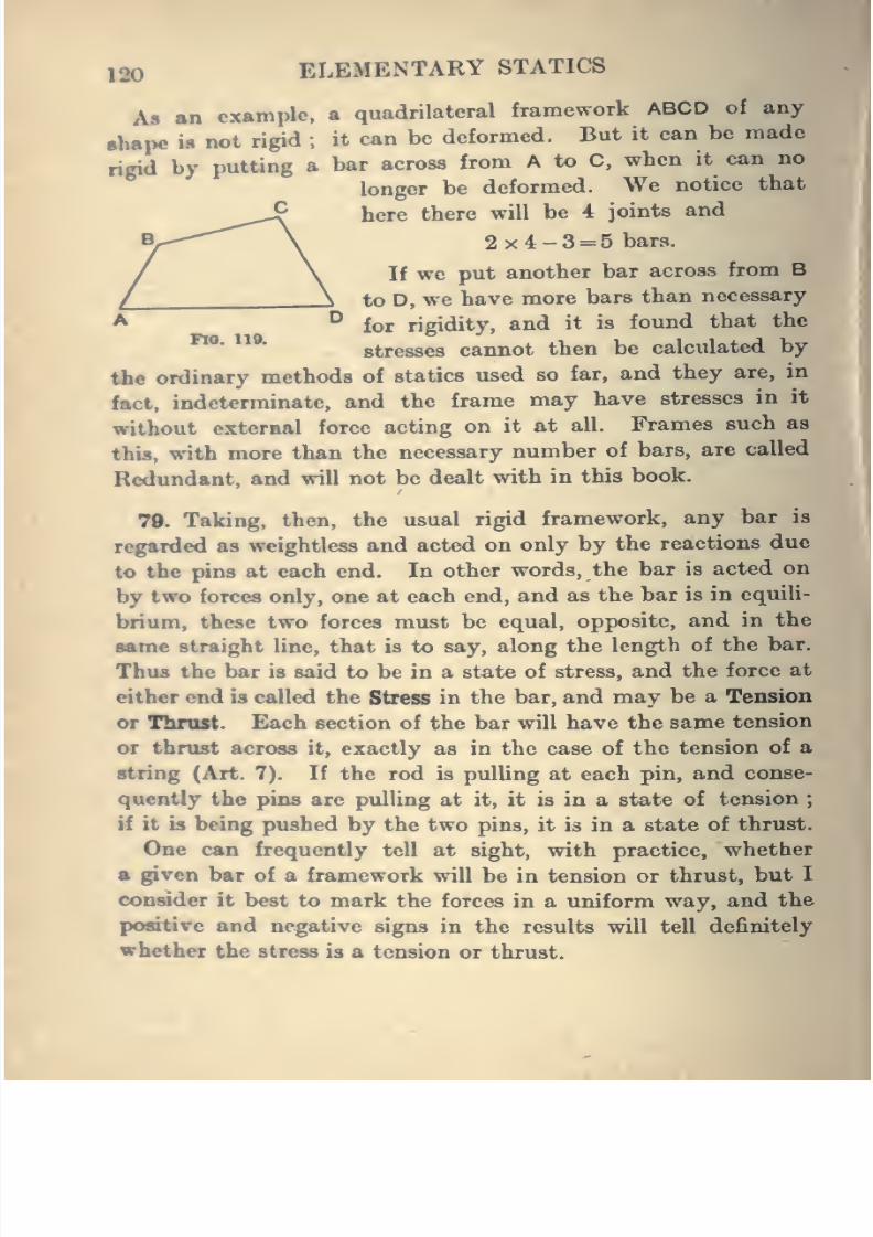
8/4/2019 Elementary Statics of 2 & Dimensions R.J.a. Barnard 1921
http://slidepdf.com/reader/full/elementary-statics-of-2-dimensions-rja-barnard-1921 132/272
120 ELEMENTARY STATICS
Afl an example, a quadrilateral framework ABCD of any
shape U not rigid ; it can be deformed. But it can be made
rigid by putting a bar across from A to C, whenit can no
longer be deformed. We notice that
here there will be 4 joints and
2x4-3 = 5 bars.
If we put another bar across from B
to D, we have more bars than necessary
for rigidity, and it is foimd that the
*^' ***"stresses cannot then be calculated by
the ordinary methods of statics used so far, and they are, in
fact, indeterminate, and the frame may have stresses in it
without external force acting on it at all. Frames such as
this, with more than the necessary number of bars, are called
Redundant, and will not be dealt with in this book.
79. Taking, then, the usual rigid framework, any bar is
regarded as weightless and acted on only by the reactions due
to the pins at each end. In other words, the bar is acted on
by two forces only, one at each end, and as the bar is in equili-
brium, these two forces must be equal, opposite, and in the
same straight line, that is to say, along the length of the bar.
Thus the baris
said to be in a state ofstress, and the force at
either end is called the Stress in the bar, and may be a Tension
or Throst. Each section of the bar will have the same tension
or thrust across it, exactly as in the case of the tension of a
string (Art. 7). If the rod is pulling at each pin, and conse-
quently the pins are pulling at it, it is in a state of tension;
if it is being pushed by the two pins, it is in a state of thrust.
One can frequently tell at sight, with practice, whether
a given bar of a framework will be in tension or thrust, but I
consider it best to mark the forces in a uniform way, and the
positive and negative signs in the results will tell definitely
whether the stress is a tension or thrust.
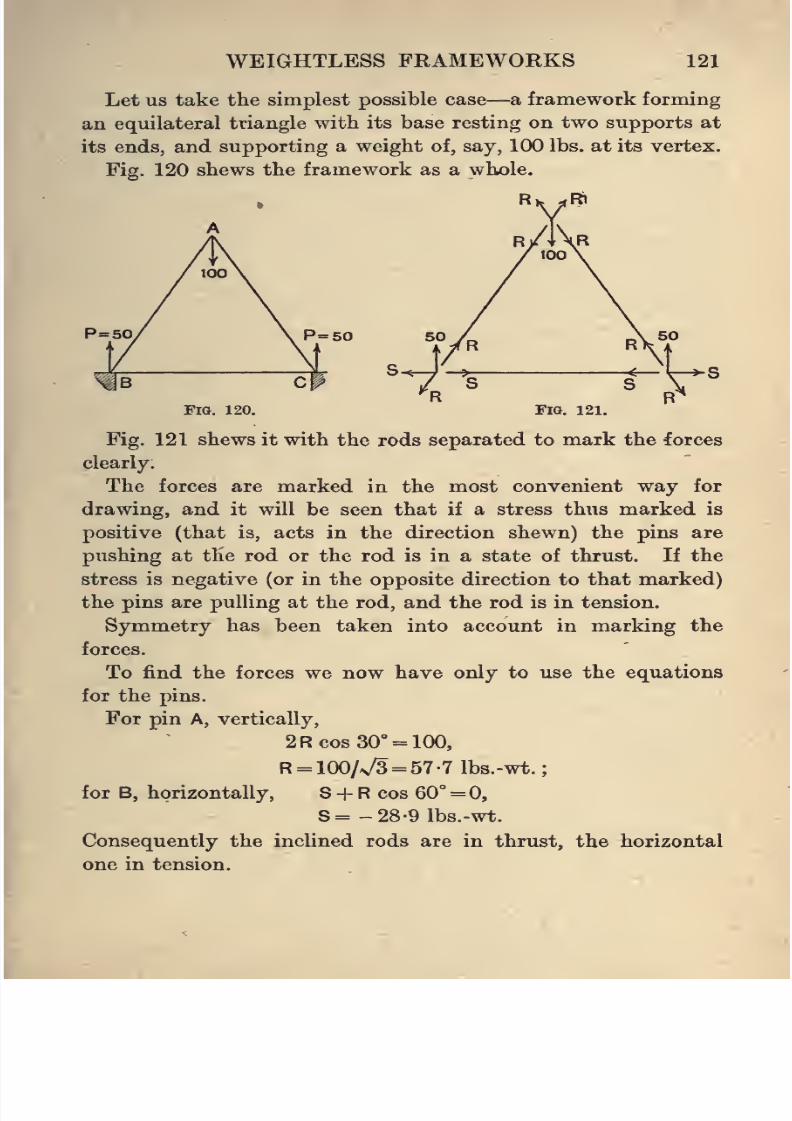
8/4/2019 Elementary Statics of 2 & Dimensions R.J.a. Barnard 1921
http://slidepdf.com/reader/full/elementary-statics-of-2-dimensions-rja-barnard-1921 133/272
WEIGHTLESS FRAMEWORKS 121
Let us take the simplest possible case—a framework forming
an equilateral triangle with its base resting on two supports at
its ends, and supporting a weight of, say, 100 lbs. at its vertex.
Fig. 120 shews the framework as a whole.
P=50 P=50
Fig. 120. Fig. 121.
Fig. 121 shews it with the rods separated to mark the forces
clearly.
The forces are marked in the most convenient way for
drawing, and it will be seen that if a stress thus marked is
positive (that is, acts in the direction shewn) the pins are
pushing at the rod or the rod is in a state of thrust. If the
stress is negative (or in the opposite direction to that marked)
the pins are pulling at the rod, and the rod is in tension.
Symmetry has been taken into account in marking the
forces.
To find the forces we now have only to use the equations
for the pins.
For pin A, vertically,
2R cos 30° = 100,
R = 100/v/3 = 57-7 1bs.-wt.;
for B, horizontally, S + R cos 60° = 0,
S= -28-9 lbs.-wt.
Consequently the inclined rods are in thrust, the horizontal
one in tension.
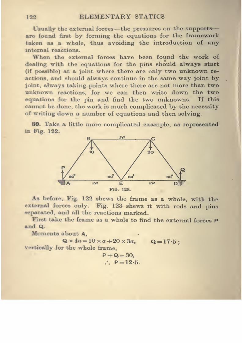
8/4/2019 Elementary Statics of 2 & Dimensions R.J.a. Barnard 1921
http://slidepdf.com/reader/full/elementary-statics-of-2-dimensions-rja-barnard-1921 134/272
122 ELEMENTARY STATICS
Usually the external forces—the pressures on the supports
arc found first by forming the equations for the framework
taken as a whole, thus avoiding the introduction of any
internal reactions.
When the external forces have been found the work of
dealing with the equations for the pins should always start
(if possible) at a joint where there are only two unknown re-
actions, and should always continue in the same way joint by
joint, always taking points where there are not more than two
unknown reactions, for we can then write down the twoequations for the pin and find the two unknowns. If this
cannot be done, the work is much complicated by the necessity
of writing down a number of equations and then solving.
80. Take a little more complicated example, as represented
in Fig. 122.
B^,^ £2 JD
4
FIO. 122.
A« before, Fig. 122 shews the frame as a whole, with the
external forces only. Fig. 123 shews it with rods and pins
separated, and all the reactions marked.
First take the frame as a whole to find the external forces P
and Q.
Momenta about A,
Qx4<i = 10xa+20x3a, Q = 17-5;
vertically for the whole frame,
P+Q = 30,
.-. P = 12-5.
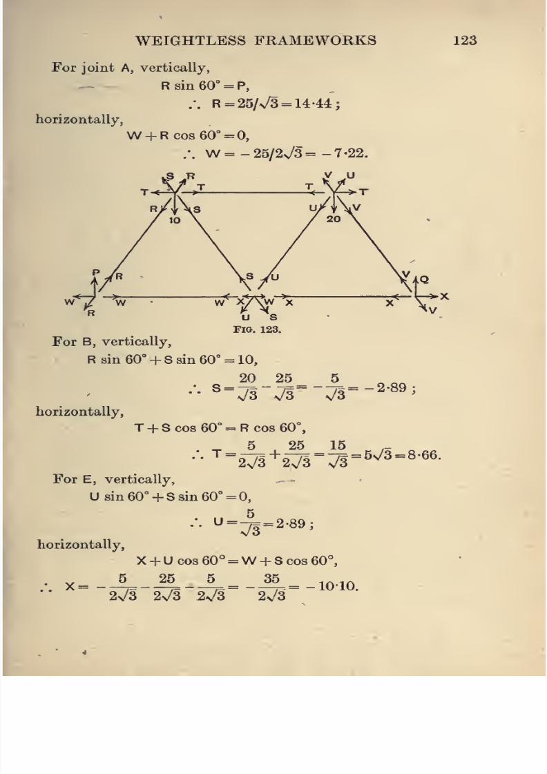
8/4/2019 Elementary Statics of 2 & Dimensions R.J.a. Barnard 1921
http://slidepdf.com/reader/full/elementary-statics-of-2-dimensions-rja-barnard-1921 135/272
WEIGHTLESS FRAMEWORKS 123
For joint A, vertically,
R sin 60° = P,
.-. R = 26lJ3 = U'U;horizontally,
W + Rcos60° = 0,
.-. W=-25/2v/3=-7-22.
kS Jt y .u
u sFig. 123.
>x
For B, vertically,
R sin 60° + S sin 60° = 10,
horizontally,
20_25_^
T + Scos60° = Rcos60°,
5 25 15^ =
27l+2Tr7r«^^= 8.66.
For E, vertically,
Usin60° + Ssin60°=0,
horizontally.
•
"=71 =
2-8^'
X + U cos 60'' =W + S cos 60°,
., x=-4-if^-A=_iB.= _io.io.
2v/3 2V3 2s/3 2V3
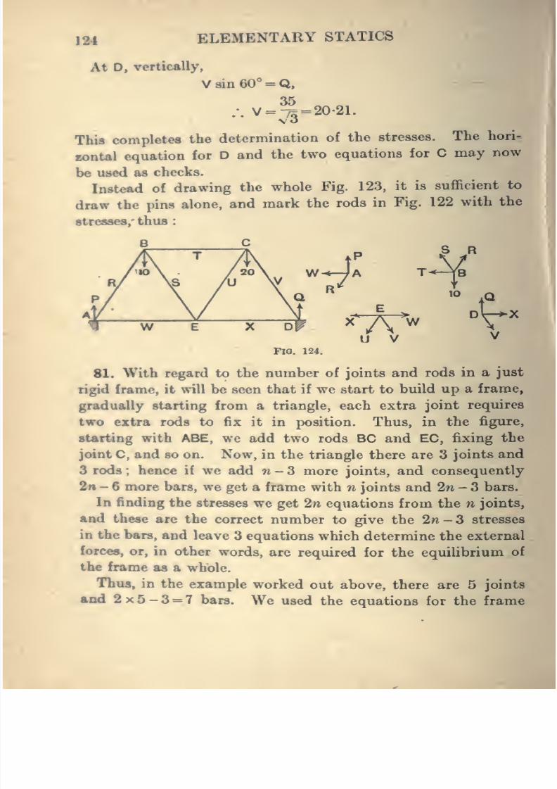
8/4/2019 Elementary Statics of 2 & Dimensions R.J.a. Barnard 1921
http://slidepdf.com/reader/full/elementary-statics-of-2-dimensions-rja-barnard-1921 136/272
124 ELEMENTARY STATICS
At D, vertically,
V8in60° = Q,
35.-. V = -75 = 20-21.
\o
Thifl completes the determination of the stresses. The hori-
rontal equation for D and the two equations for C may now
be used as checks.
Instead of drawing the whole Fig. 123, it is sufficient to
draw the pins alone, and mark the rods in Fig. 122 with the
stresses/ thus
FlO. 124.
81. With regard to the number of joints and rods in a just
rigid frame, it will be seen that if we start to build up a frame,
gradually starting from a triangle, each extra joint requires
two extra rods to fix it in position. Thus, in the figure,
starting with ABE, we add two rods BC and EC, fixing the
joint C, and so on. Now, in the triangle there are 3 joints and
3 rods ; hence if we add n - 3 more joints, and consequently
2f» - 6 more bars, we get a frame with n joints and 2n - 3 bars.
In finding the stresses we get 2n equations from the n joints,
and these are the correct number to give the 2n-3 stresses
in the bars, and leave 3 equations which determine the external
forces, or, in other words, are required for the equilibrium of
the frame as a whole.
Thus, in the example worked out above, there are 5 joints
and 2x5-3 = 7 bars. We used the equations for the frame
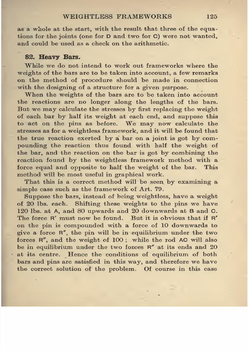
8/4/2019 Elementary Statics of 2 & Dimensions R.J.a. Barnard 1921
http://slidepdf.com/reader/full/elementary-statics-of-2-dimensions-rja-barnard-1921 137/272
WEIGHTLESS FRAMEWORKS 125
as a whole at the start, with the result that three of the equa-
tions for the joints (one for D and two for C) were not wanted,
and could be used as a check on the arithmetic.
82. Heavy Bars.
While we do not intend to work out frameworks where the
weights of the bars are to be taken into account, a few remarks
on the method of procedure should be made in connection
with the designing of a structure for a given purpose.
When the weights of the bars are to be taken into accountthe reactions are no longer along the lengths of the bars.
But we may calculate the stresses by first replacing the weight
of each bar by half its weight at each end, and suppose this
to act on the pins as before. We may now calculate the
stresses as for a weightless framework, and it will be found that
the true reaction exerted by a bar on a joint is got by com-
pounding the reaction thus found with half the weight of
the bar, and the reaction on the bar is got by combining the
reaction found by the weightless framework method with a
force equal and opposite to half the weight of the bar. This
method will be most useful in graphical work.
That this is a correct method will be seen by examining a
simple case such as the framework of Art. 79.
Suppose the bars, instead of being weightless, have a weight
of 20 lbs. each. Shifting these weights to the pins we have
120 lbs. at A, and 80 upwards and 20 downwards at B and C.
The force R' must now be found. But it is obvious that if R'
on the pin is compounded with a force of 10 downwards to
give a force R", the pin will be in equilibrium under the two
forces R", and the weight of 100;
while the rod AC will also
be in equilibrium under the two forces R" at its ends and 20
at its centre. Hence the conditions of equilibrium of both
bars and pins are satisfied in this way, and therefore we have
the correct solution of the problem. Of course in this case
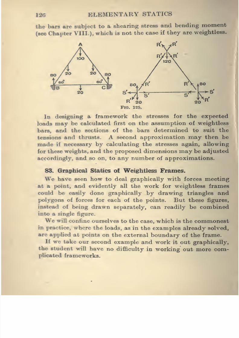
8/4/2019 Elementary Statics of 2 & Dimensions R.J.a. Barnard 1921
http://slidepdf.com/reader/full/elementary-statics-of-2-dimensions-rja-barnard-1921 138/272
126 ELEMENTARY STATICS
the bars are subject to a shearing stress and bending moment
(see Chapter VIII.). which is not the case if they are weightless.
In designing a framework the stresses for the expected
loads may be calculated first on the assumption of weightless
bars, and the sections of the bars determined to suit the
tensions and thrusts. A second approximation may then bemade if necessary by calculating the stresses again, allowing
for these weights, and the proposed dimensions may be adjusted
accordingly, and so on, to any number of approximations.
88. Graphical Statics o! Weightless Frames.
We have seen how to deal graphically with forces meeting
at a point, and evidently all the work for weightless frames
could be easily done graphically by drawing triangles and
polygons of forces for each of the points. But these figures,
instead of being drawn separately, can readily be combined
into a single figure.
We will confine ourselves to the case, which is the commonest
in practice, where the loads, as in the examples already solved,
are applied at points on the external boundary of the frame.
If we take our second example and work it out graphically,
the student will have no difficulty in working out more com-
plicated frameworks.
II
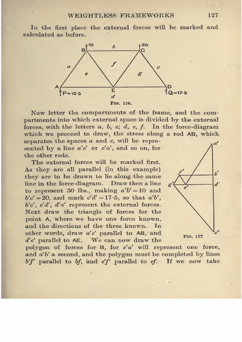
8/4/2019 Elementary Statics of 2 & Dimensions R.J.a. Barnard 1921
http://slidepdf.com/reader/full/elementary-statics-of-2-dimensions-rja-barnard-1921 139/272
WEIGHTLESS FRAMEWORKS 127
In the first place the external forces will be marked and
calculated as before.
Now letter the compartments of the frame, and the com-
partments into which external space is divided by the external
forces, with the letters a, b, c, d, e, f.In the force-diagram
which we proceed to draw, the stress along a rod AB, which
separates the spaces a and e, will be repre-
sented by a line a'e' or e'a', and so on, for
the other rods.
The external forces will be marked first.
As they are all parallel (in this example)
they are to be drawn to lie along the same
line in the force-diagram. Draw then a line
to represent 30 lbs., making a'b' = 10 and
h'c' = 20, and mark c'd' = ll-b, so that a'b',
b'c, c'd', d'a' represent the external forces.
Next draw the triangle of forces for the
point A, where we have one force known,
and the directions of the three known. In
other words, draw a'e' parallel to AB, andd'e' parallel to AE. We can now draw the
polygon of forces for B, for e'a' will represent one force,
and a'b' a second, and the polygon must be completed by lines
b'f parallel to bf, and e'f parallel to ef. If we now take
Fig. 127.
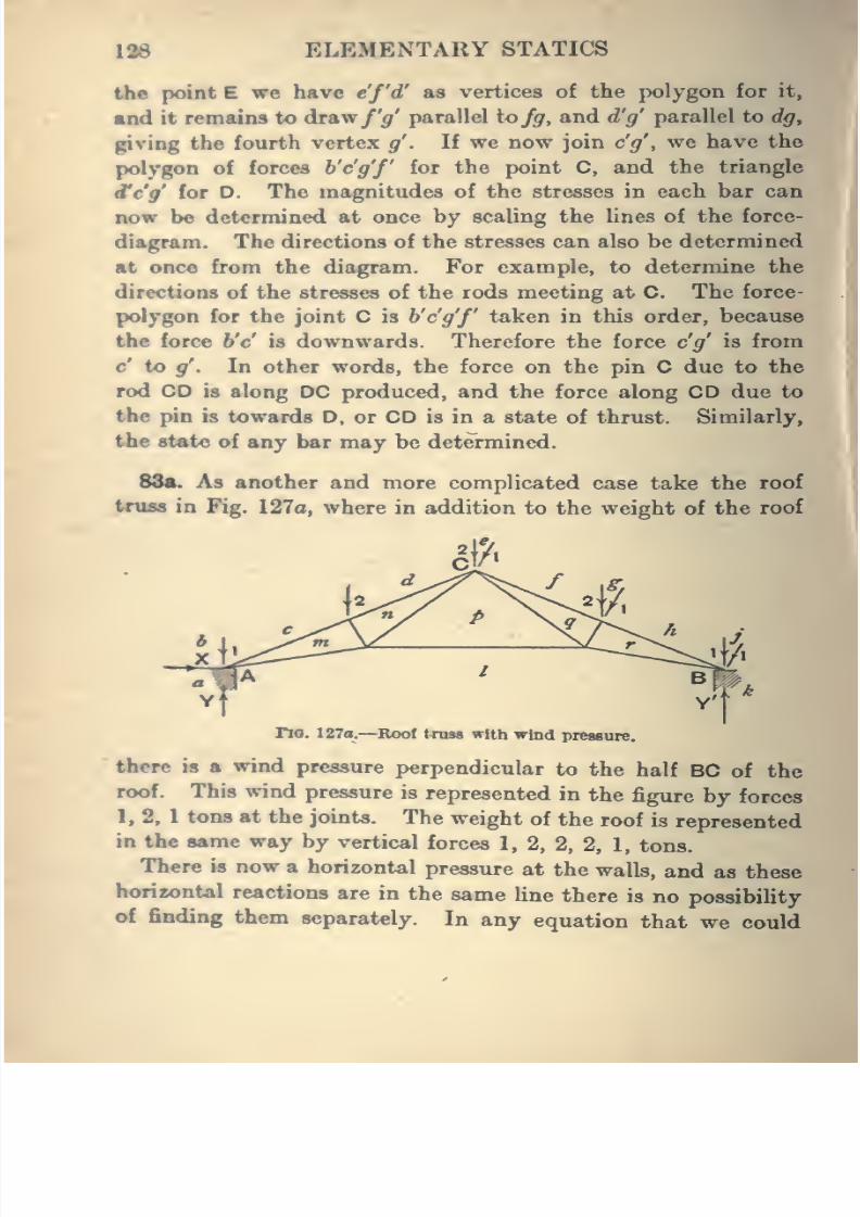
8/4/2019 Elementary Statics of 2 & Dimensions R.J.a. Barnard 1921
http://slidepdf.com/reader/full/elementary-statics-of-2-dimensions-rja-barnard-1921 140/272
138 ELEMENTARY STATICS
the point E we have c'/'d' as vertices of the polygon for it,
and it remains to dr&wf'g' parallel tofg, and d'g' parallel to dg,
giving the fourth vertex g'. If we now join c'g', we have the
polygon of forces b'c'g'f for the point C, and the triangle
d'c'g' for D. The magnitudes of the stresses in each bar can
now be determined at once by scaling the lines of the force-
diagram. The directions of the stresses can also be determined
at once from the diagram. For example, to determine the
directions of the stresses of the rods meeting at C. The force-
polygon for the joint C is b'c'g'f taken in this order, because
the force b'c' is downwards. Therefore the force c'g' is from
c* to 5^. In other words, the force on the pin C due to the
rod CD is along DC produced, and the force along CD due to
the pin is towards D, or CD is in a state of thrust. Similarly,
the state of any bar may be determined.
88a. As another and more complicated case take the roof
truss in Fig. 127a, where in addition to the weight of the roof
J
rio. 127o.—Roof truss with wind pressure.
there is a wind pressure perpendicular to the half BC of the
roof. This wind pressure is represented in the figure by forces
1, 2, 1 tons at the joints. The weight of the roof is represented
in the same way by vertical forces 1, 2, 2, 2, 1, tons.
There is now a horizontal pressure at the walls, and as these
horizontal reactions are in the same line there is no possibility
of finding them separately. In any equation that we could
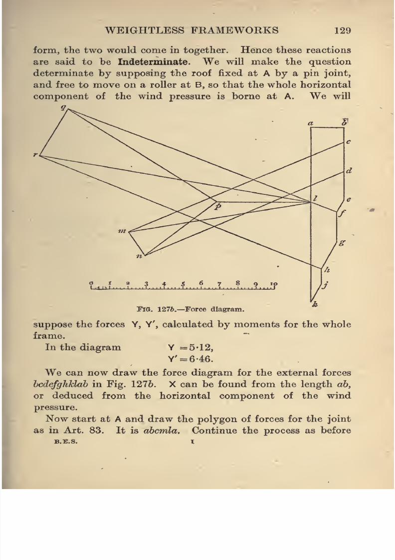
8/4/2019 Elementary Statics of 2 & Dimensions R.J.a. Barnard 1921
http://slidepdf.com/reader/full/elementary-statics-of-2-dimensions-rja-barnard-1921 141/272
WEIGHTLESS FKAMEWORKS 129
form, the two would come in together. Hence these reactions
are said to be Indeterminate. We will make the question
determinate by supposing the roof fixed at A by a pin joint,
and free to move on a roller at B, so that the whole horizontal
component of the wind pressure is borne at A. We will
Fig. 1276.—Force diagram.
suppose the forces Y, Y', calculated by moments for the whole
frame.
In the diagram Y =5*12,
Y' = 646.
We can now draw the force diagram for the external forces
hcdefghklab in Fig. 1276. X can be found from the length ab,
or deduced from the horizontal component of the wind
pressure.
Now start at A and draw the polygon of forces for the joint
as in Art. 83. It is ahcmla. Continue the process as before
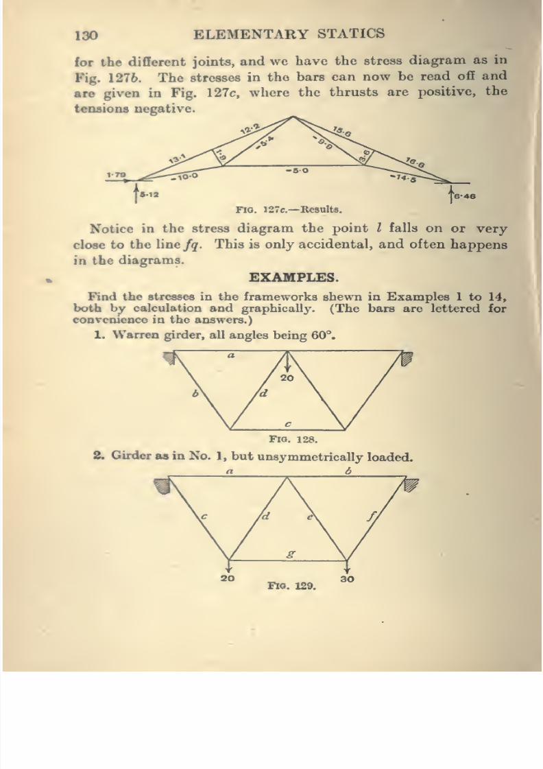
8/4/2019 Elementary Statics of 2 & Dimensions R.J.a. Barnard 1921
http://slidepdf.com/reader/full/elementary-statics-of-2-dimensions-rja-barnard-1921 142/272
lao ELEMENTARY STATICS
for the different joints, and we have the stress diagram as in
Fig. 1276. The stresses in the bars can now be read off and
are given in Fig. 127c, where the thrusts are positive, the
tensions negative.
Fio. 127e.—Besults.
Notice in the stress diagram the point / falls on or very
close to the line fq. This is only accidental, and often happens
in the diagrams.
EXAMPLES.
Find the stresses in the frameworks shewn in Examples 1 to 14,
both by calculation and graphically. (The bars are lettered for
coDTcnicDce in the answers.)
L Warren girder, all angles being 60°.
I
FlQ. 128.
2. Girder as in No. 1, but unsymmetrically loaded.
Fro. 129.
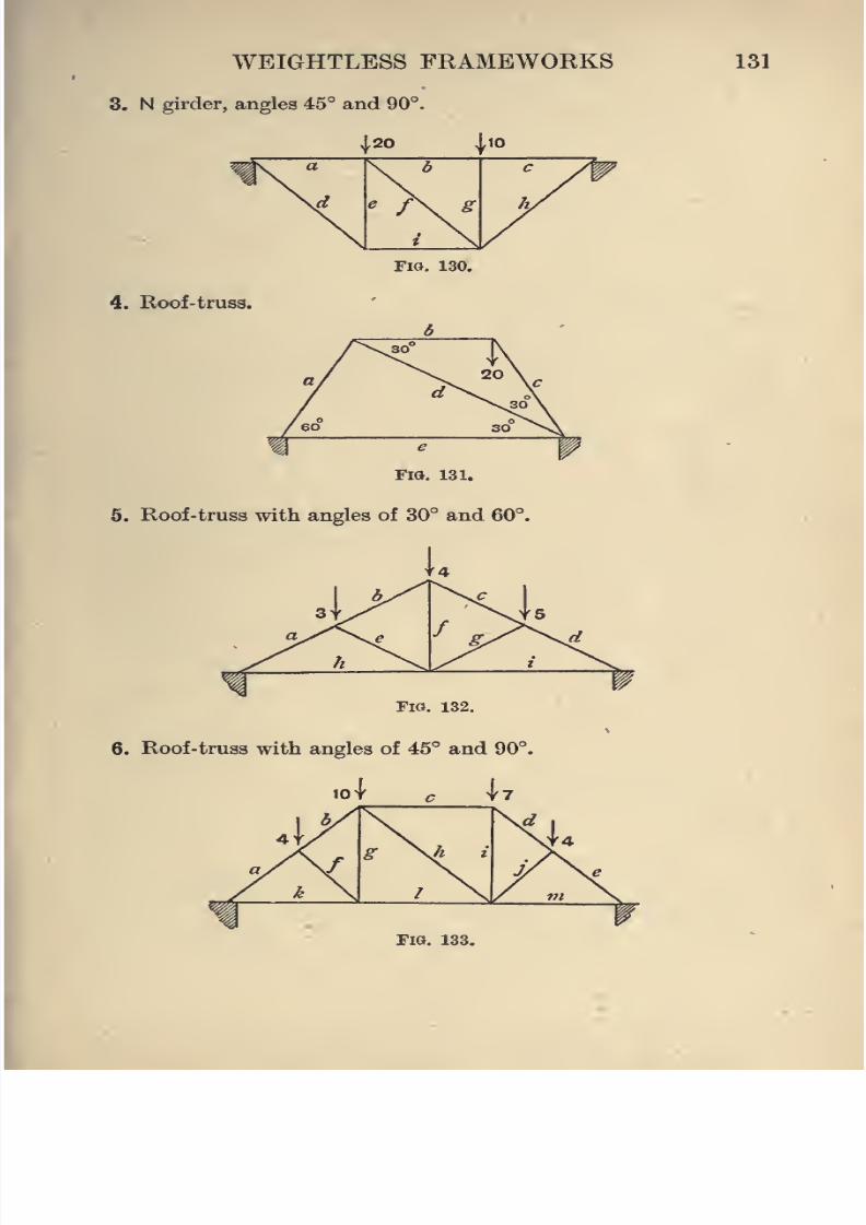
8/4/2019 Elementary Statics of 2 & Dimensions R.J.a. Barnard 1921
http://slidepdf.com/reader/full/elementary-statics-of-2-dimensions-rja-barnard-1921 143/272
WEIGHTLESS FKAMEWORKS
3. N girder, angles 45° and 90°.
131
..20 ,,10
i\ ^ \* c /|
\d g
\y
Fig. 130.
4. Roof-truss.
FlO, 131.
5. Roof-truss with angles of 30° and 60°.
Fig. 132.
6. Roof-truss with angles of 45° and 90°
FIO. 133.
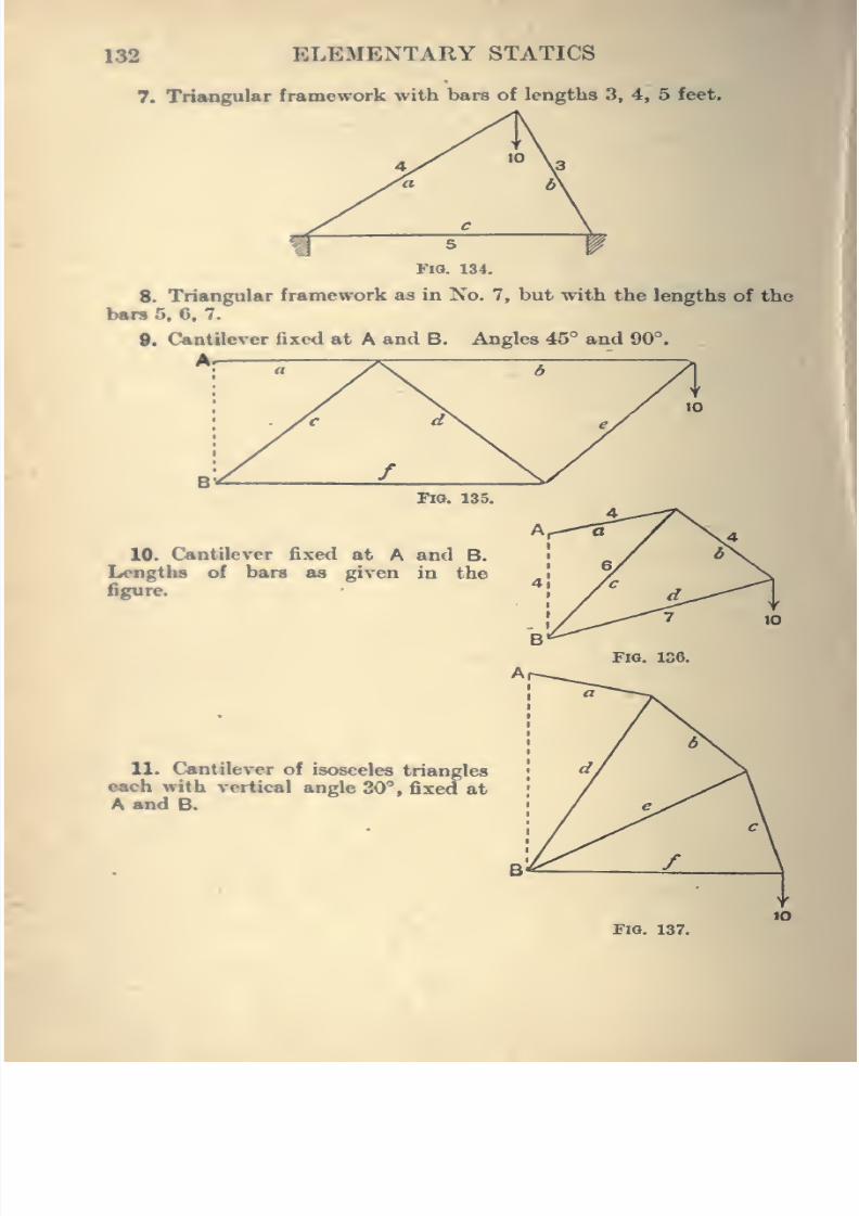
8/4/2019 Elementary Statics of 2 & Dimensions R.J.a. Barnard 1921
http://slidepdf.com/reader/full/elementary-statics-of-2-dimensions-rja-barnard-1921 144/272
132 ELEMENTARY STATICS
7. Triangular framework with bars of lengths 3, 4, 5 feet.
Fio. 134.
8. Triangular framework as in No. 7, but with the lengths of the
ban 5, 6, 7.
9. Cantilever fixed at A and B. Angles 45° and 90°.
yFig. 135.
10. Cantilever fixed at A and B.
Lengths of bars as given in the
figure.
11. Cantilever of isosceles triangles
each with vertical angle 30°, fixed at
A and B.
Fio. 137.
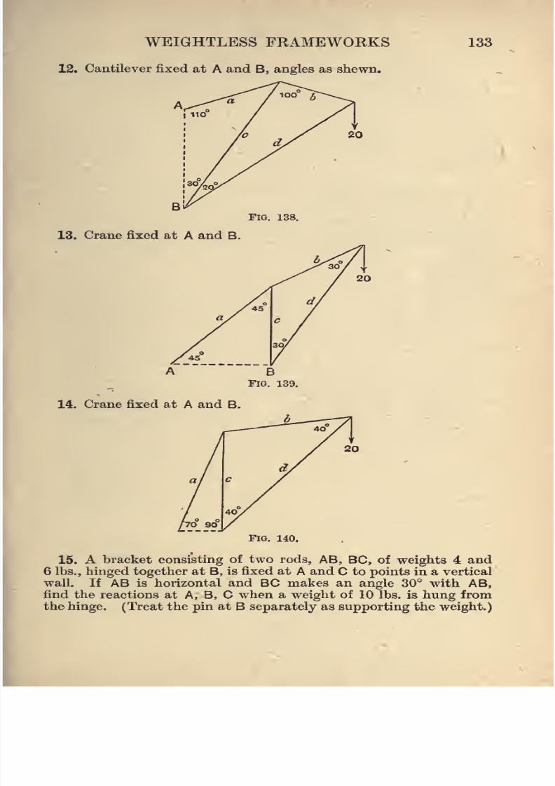
8/4/2019 Elementary Statics of 2 & Dimensions R.J.a. Barnard 1921
http://slidepdf.com/reader/full/elementary-statics-of-2-dimensions-rja-barnard-1921 145/272
WEIGHTLESS FRAMEWORKS
12. Cantilever fixed at A and B, angles as shewn.
133
Fig. 138.
13. Crane fixed at A and B.
14. Crane fixed at A and B.
Fig. 140.
15. A bracket consisting of two rods, AB, BC, of weights 4 and
6 lbs., hinged together at B, is fixed at A and C to points in a vertical
wall. If AB is horizontal and BC makes an angle 30° with AB,
find the reactions at A, B, C when a weight of 10 lbs. is hung from
the hinge. (Treat the pin at B separately as supporting the weight.)
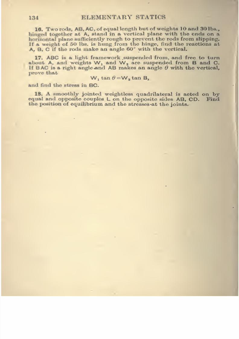
8/4/2019 Elementary Statics of 2 & Dimensions R.J.a. Barnard 1921
http://slidepdf.com/reader/full/elementary-statics-of-2-dimensions-rja-barnard-1921 146/272
134 ELEMENTARY STATICS
16. Two rods, AB, AC, of equal length but of weights 10 and 30 lbs.,
hiosed together at A, stand in a vertical plane with the ends on a
bonzontal plane sufficiently rough to prevent the rods from slipping.
If a weight of 50 lbs.is
hung from the hinge, find the reactions atA, B. C if the rods make an angle 60^ with the vertical.
17. ABC is a light framework suspended from, and free to turn
alx>ut A, and weights Wi and Wj are suspended from B and C.
If BAC is a right angle«nd AB makes an angle d with the vertical,
prove that
W, tan^=W,tanB,
and find the stress in BC.
18. A smoothly jointed weightless quadrilateral is acted on byequal and opposite couples L on the opposite sides AB, CD. Findthe position of equilibrium and the stresses^at the joints.
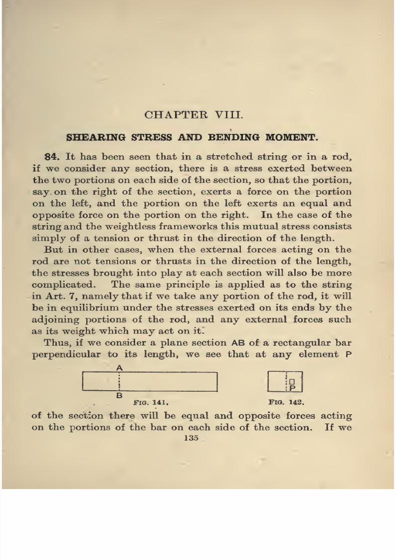
8/4/2019 Elementary Statics of 2 & Dimensions R.J.a. Barnard 1921
http://slidepdf.com/reader/full/elementary-statics-of-2-dimensions-rja-barnard-1921 147/272
CHAPTER VIIL
SHEARING STRESS AND BENDING MOMENT.
84. It has been seen that in a stretched string or in a rod,
if we consider any section, there is a stress exerted between
the two portions on each side of the section, so that the portion,
say on the right of the section, exerts a force on the portion
on the left, and the portion on the left exerts an equal and
opposite force on the portion on the right. In the case of the
stringand
the weightlessframeworks
this
mutualstress consists
simply of a tension or thrust in the direction of the length.
But in other cases, when the external forces acting on the
rod are not tensions or thrusts in the direction of the length,
the stresses brought into play at each section will also be more
complicated. The same principle is applied as to the string
in Art. 7, namely that if we take any portion of the rod, it will
be in equilibrium under the stresses exerted on its ends by the
adjoining portions of the rod, and any external forces such
as its weight which may act on it.
Thus, if we consider a plane section AB of a rectangular bar
perpendicular to its length, we see that at any element P
A
BFig. 141. Fio. 142.
of the section there will be equal and opposite forces acting
on the portions of the bar on each side of the section. If we
135
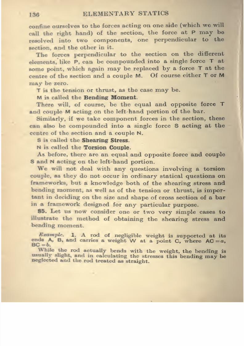
8/4/2019 Elementary Statics of 2 & Dimensions R.J.a. Barnard 1921
http://slidepdf.com/reader/full/elementary-statics-of-2-dimensions-rja-barnard-1921 148/272
13e ELEMENTARY STATICS
confine ourselves to the forces acting on one side (which we will
call the right hand) of the section, the force at P may bo
resolved into two components, one perpendicular to the
section, and the other in it.
The forces iMjrpendicular to the section on the different
elements, like P, can be compounded into a single force T at
acme point, which again may be replaced by a force T at the
centre of the section and a couple M. Of course either T or M
nuy be zero.
T is the tension or thrust, as the case may be.
M is called the Bending Moment.
There will, of course, be the equal and opposite force T
and couple M acting on the left hand portion of the bar.
Similarly, if we take component forces in the section, these
can also be compounded into a single force S acting at the
centre of the section and a couple N.
S is called the Shearing Stress.
N is called the Torsion Couple.
As before, there are an equal and opposite force and couple
8 and N acting on the left-hand portion.
We will not deal with any questions involving a torsion
couple, as they do not occur in ordinary statical questions on
frameworks, but a knowledge both of the shearing stress and
bending moment, as well as of the tension or thrust, is impor-
tant in deciding on the size and shape of cross section of a bar
in a framework designed for any particular purpose.
85. Let us now consider one or two very simple cases to
illustrate the method of obtaining the shearing stress and
bending moment.
Examplt. 1. A rod of negligibleweight
is
supported atits
ends A, B, and carries a weight W at a point C, where AC =o,BC=6.While the rod actually bends with the weight, the bending is
usoaliy slight, and in calculating the stresses this bending may beneglected and the rod treated as straight.
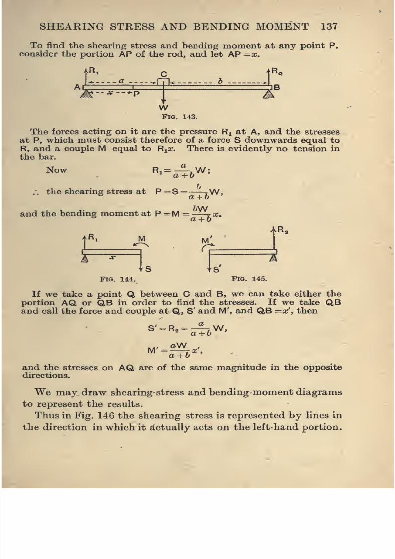
8/4/2019 Elementary Statics of 2 & Dimensions R.J.a. Barnard 1921
http://slidepdf.com/reader/full/elementary-statics-of-2-dimensions-rja-barnard-1921 149/272
SHEARING STRESS AND BENDING MOMENT 137
To find the shearing stress and bending moment at any point P,
consider the portion AP of the rod, and let AP =a;.
kR,
At..a -.-.^[71^
|R«
•-- X --*-p
WFig. 143.
The forces acting on it are the pressure R^ at A, and the stresses
at P, which must consist therefore of a force S downwards equal to
R, and a couple M equal to R^x. There is evidently no tension in
the bar.
Now
the shearing stress at P =S
"-a-i**^
a +6W,
and the bending moment at P =M = —7 cc.° a+h
|R,AR,
+s'
FlO. 144. Fig. 145.
If we take a point Q between C and B, we can take either the
portion AQ or QB in order to find the stresses. If we take QBand call the force and couple at Q, S' and M', and QB =«', then
a+0
and the stresses on AQ are of the same magnitude in the opposite
directions.
We may draw shearing-stress and bending-moment diagrams
to represent the results.
Thus in Fig. 146 the shearing stress is represented by lines in
the direction in which it d^ctually acts on the left-hand portion.
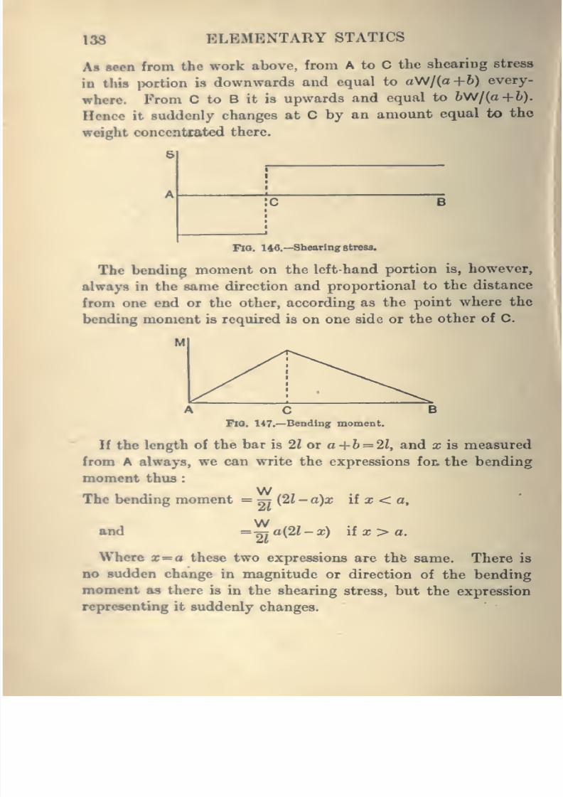
8/4/2019 Elementary Statics of 2 & Dimensions R.J.a. Barnard 1921
http://slidepdf.com/reader/full/elementary-statics-of-2-dimensions-rja-barnard-1921 150/272
138 ELEMENTARY STATICS
Ab seen from the work above, from A to C the sheariDg stress
in this portion is downwards and equal to aW/(a+6) every-
where. From C to B it is upwards and equal to b\N/{a+h).
Hence it suddenly changes at C by an amount equal to the
weight concentiated there.
B
Fio. 146.—Shearing stress.
The bending moment on the left-hand portion is, however,
always in the same direction and proportional to the distance
from one end or the other, according as the point where the
bending moment is required is on one side or the other of C.
Fio. 147.—Bending moment.
If the length of the bar is 21 or a +6 = 2?, and x is measured
from A always, we can write the expressions fot the bending
moment thus
WThe bending moment = ^ {21- a)x if a; < a,
and
21
W= -^a{2l-x) iix>a.
Where x= a these two expressions are thfe same. There is
no sudden change in magnitude or direction of the bending
moment as there is in the shearing stress, but the expression
representing it suddenly changes.
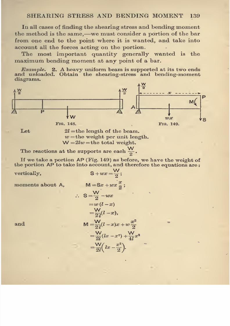
8/4/2019 Elementary Statics of 2 & Dimensions R.J.a. Barnard 1921
http://slidepdf.com/reader/full/elementary-statics-of-2-dimensions-rja-barnard-1921 151/272
SHEARING STRESS AND BENDING MOMENT 139
In all cases of finding the shearing stress and bending moment
the method is the same,—we must consider a portion of the bar
from one end to the point where it is wanted, and take into
account all the forces acting on the portion.
The most important quantity generally wanted is the
maximum bending moment at any point of a bar.
Example. 2.
and unloaded,
diagrams.
A heavy uniform beam is supported at its two ends
Obtain the shearing-stress and bending-moment
aW
iW
A+W
Fig. 148.
Let 2l=the length of the beam.
w = the weight per unit length.
W —2liu =the total weight.
WThe reactions at the supports are each —
wx
Fig. 149.
'I'S
If we take a portion AP (Fig. 149) as before, we have the weight of
the portion AP to take into account, and therefore the equations are
vertically,
moments about A, 2'
and
M =Sx +WX
=w{l -x)
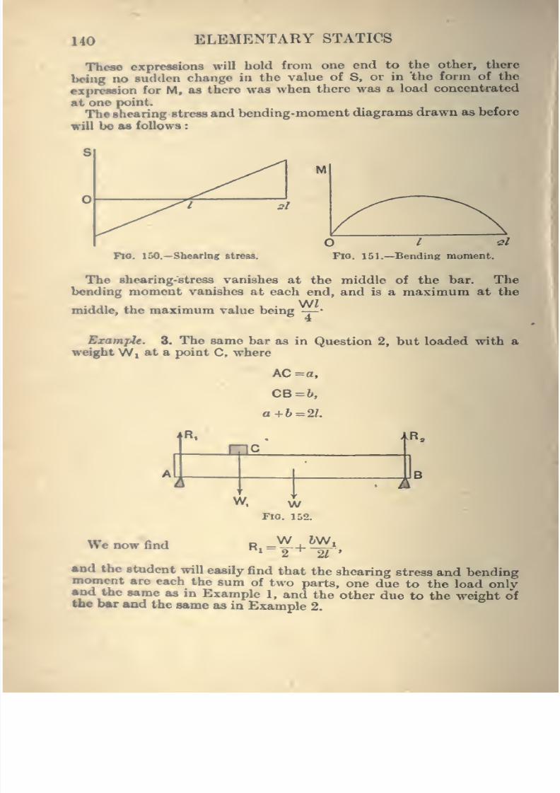
8/4/2019 Elementary Statics of 2 & Dimensions R.J.a. Barnard 1921
http://slidepdf.com/reader/full/elementary-statics-of-2-dimensions-rja-barnard-1921 152/272
140 ELEMENTARY STATICS
Tbeao expressions will hold from one end to the other, there
being no sudden change in the value of S, or in 'the form of the
expreasion for M, as there was when there was a load concentrated
At onepoint.
The saearing stress and bending-moment diagrams drawn as before
will be aa follows
Fio. 150.—Sbeftring stress.
O I 2l
Fio. 151.—Bending moment.
The shearing-stress vanishes at the middle of the bar. The
bending moment vanishes at each end, and is a maximum at the
middle, the maximum value being -j-*
ExampU. 8. The same bar as in Question 2, but loaded with aweight Wi at a point C, where
AC = a.
CB=b,
a +1=21.
R,
mc*..
A.ii
V^. \V
A
Fio. 152.
We now find R -WRi-2- 5Wi*21
'
and the student will easily find that the shearing stress and bendingmoment are each the sum of two parts, one due to the load onlyand the same as in Example 1, and the other due to the weight oftoe bar and the same as in Example 2.
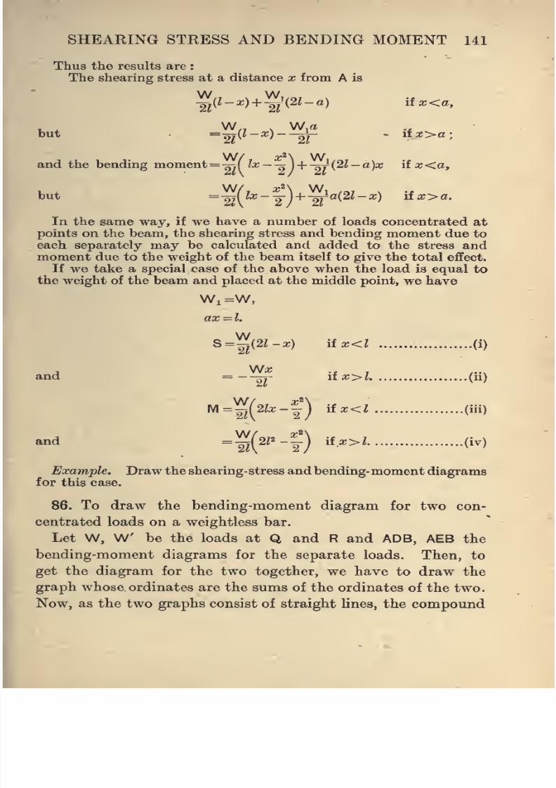
8/4/2019 Elementary Statics of 2 & Dimensions R.J.a. Barnard 1921
http://slidepdf.com/reader/full/elementary-statics-of-2-dimensions-rja-barnard-1921 153/272
SHEARING STEESS AND BENDING MOMENT 141
Thus the results are
The shearing stress at a distance x from A is
W W,
but"^M^ '~~2r
* ii2;>a;
W/ x^\ W,and the bending moment= -s-.(
lx~-x\+ -^{2l-a)x \ix<a,
but =-2tU«- 2")+ "27 «(2t-a;) u.x>a.
In the same way, if we have a number of loads concentrated at
points on the beam, the shearing stress and bending moment due to
each separately may be calculated and added to the stress andmoment due to the weight of the beam itself to give the total effect.
If we take a special case of the above when the load is equal to
the weight of the beam and placed at the middle point, we have
Wi=W,
ax=l.
S='^A2l-x) itx<l (i)2V
'21nd =-—^- iix>l (ii)
M
and
Example. Draw the shearing-stress and bending-moment diagrams
for this case.
86. To draw the bending-moment diagram for two con-
centrated loads on a weightless bar.
Let W, W be the loads at Q and R and ADB, AEB thebending-moment diagrams for the separate loads. Then, to
get the diagram for the two together, we have to draw the
graph whose ordinates are the sums of the ordinates of the two.
Now, as the two graphs consist of straight lines, the compound
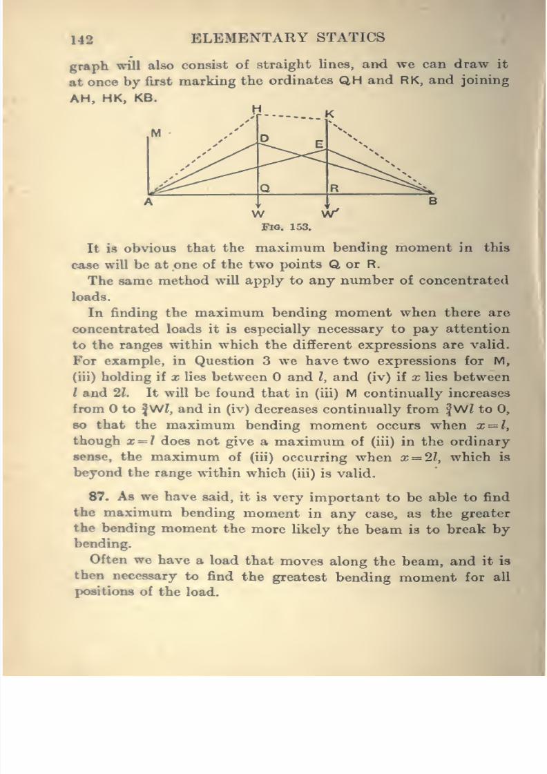
8/4/2019 Elementary Statics of 2 & Dimensions R.J.a. Barnard 1921
http://slidepdf.com/reader/full/elementary-statics-of-2-dimensions-rja-barnard-1921 154/272
142 ELEMENTARY STATICS
graph will also consist of straight lines, and we cjan draw it
at once by first marking the ordinates QH and RK, and joining
AH, HK, KB.
W- K
W W'FIO. 153.
It is obvious that the maximum bending moment in thSf
case will be at one of the two points Q or R.
The same method will apply to any number of concentrated
loads.
Infinding the
maximumbending
momentwhen there are
concentrated loads it is especially necessary to pay attention
to the ranges within which the different expressions are valid.
For example, in Question 3 we have two expressions for M,
(iii) holding if x lies between and I, and (iv) if x lies between
I and 1\. It will be found that in (iii) M continually increases
from to |Wi, and in (iv) decreases continually from |W^ to 0,
BO that the maximum bending moment occurs when x — l,
though x = / does not give a maximum of (iii) in the ordinary
sense, the maximum of (iii) occurring when x = 2l, which is
beyond the range within which (iii) is valid.
87. As we have said, it is very important to be able to find
the maximum bending moment in any case, as the greater
the bending moment the more likely the beam is to break bybending.
Often we have a load that moves along the beam, and it is
then necessary to find the greatest bending moment for all
poMtions of the load.
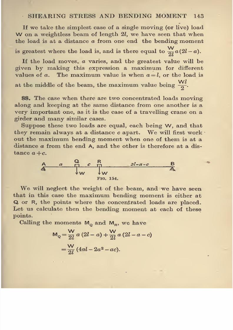
8/4/2019 Elementary Statics of 2 & Dimensions R.J.a. Barnard 1921
http://slidepdf.com/reader/full/elementary-statics-of-2-dimensions-rja-barnard-1921 155/272
SHEARING STRESS AND BENDING MOMENT 143
If we take the simplest case of a single moving (or live) load
W on a weightless beam of length 21, we have seen that when
the load is at a distance a from one end the bending moment
Wis greatest where the load is, and is there equal to -^a(2Z-a).
If the load moves, a varies, and the greatest value will be
given by making this expression a maximum for difierent
values of a. The maximum value is when a = l, or the load is
WZat the middle of the beam, the maximum value being -^.
88. The case when there are two concentrated loads moving
along and keeping at the same distance from one another is a
very important one, as it is the case of a travelling crane on a
girder and many similar cases.
Suppose these two loads are equal, each being W, and that
they remain always at a distance c apart. We will first work
out the maximum bending moment when one of them is at a
distance a from the end A, and the other is therefore at a dis-
tance a-\-c.
A Q R ,r e
W \\N
Fia. 154.
We will neglect the weight of the beam, and we have seen
that in this case the maximum bending moment is either at
Q or R, the points where the concentrated loads are placed.
Let us calculate then the bending moment at each of these
points.
Calling the moments M^ and M^, we have
W WMq =
2^a (2Z - a) + ^7 a (2Z - a - c)
W= nT (4aZ - 2a^ - ac).
8/4/2019 Elementary Statics of 2 & Dimensions R.J.a. Barnard 1921
http://slidepdf.com/reader/full/elementary-statics-of-2-dimensions-rja-barnard-1921 156/272
•I
144 ELEMENTARY STATICS
w wM„ = -^{2l-a-c) + -^{a+c){2l-a-c)
w= -g(2a+c)(2Ua-c)
= -g(4a?-2a2+2fc-3ac-c2) (i)
wMQ-M„ = ^^{2ac-2fc+c«)
w= -^c(2a-2/+c)
= 2^c{a-(2?-a-c)}.
.*. Mq>Mp if a>2l-a-c,
i.e. if AQ>RB.
In other words, the maximum bending moment is at that
one of the points Q or R which is nearest to the centre of the
beam.Now, as the load travels from A towards B, R is nearer to
the centre until a = l-^. We will find when M„ is a maximum.
, Now, by (i), wM„ = -^(4ai-2a2+2fc-3ac-c2),
and for different values of a this is a maximum when
U-ia-Zc = 0,
or a = l-^c,
this value being within the assigned limits for a (less than
^-ic) gives the solution of the problem, and by (i)
WM„^=2^(2Z-a-c)(2a+c)
=^(2Z-c-Z+ |c)(2/-|+c)
= ^(^-ic)(2Z-Jc)
t('-|)'
8/4/2019 Elementary Statics of 2 & Dimensions R.J.a. Barnard 1921
http://slidepdf.com/reader/full/elementary-statics-of-2-dimensions-rja-barnard-1921 157/272
SHEARING STRESS AND BENDING MOMENT 145
EXAMPLES.
1. Find the shearing stress and bending moment at any point
of a cantilever (a horizontal beam fixed at one end and free at theother) of weightW and loaded with a weightW at the free end.
2. Find the shearing stress and bending moment at points on a
heavy beam of length 2Z resting symmetrically on supports at a
distance 2a from one another.
3. A beam is 20 ft. long and weighs 12 cwt. It rests on supports
at its ends. Find the maximum bending moment due to its ownweight and to a load of | ton at its centre.
4. With the same beam as in Question 3, find the bending momentat any point for a load of 8 cwt. at a distance of 5 ft. from one end
;
find also where this bending moment is a maximum, and find its
maximum value.
Compare the gradients of the bending-moment curve at points on
the two sides of the load and close to it.
Find also the shearing stress at any point, the points where it is
a maximum and minimum, and the maximum and minimum values.
5. A beam 20 ft. long and weighing a ton is supported at the
ends and loaded with concentrated loads of J ton each at four points
at 4, 8, 12, 16 ft. from one end. Find expressions for the shearing
stress and bending moment at all points, obtaining the numerical
values at 5 and 10 ft. from the end.
Draw the shearing-stress and bending-moment diagrams.
6. Find the shearing stress and bending moment at any point
in a cantilever, as in Question 1, 12 ft. long and weighing 8 cwt.,
with a load of 4 cwt. at the free end.
Find the maximum value of each.
7. A truck of weight 4 tons, borne equally by the four wheels,
has its axles 10 ft. apart, and it passes along a pair of girders 50 ft.
long supported at the ends of each. What is the maximum bending
moment due to the truck on one girder for any position of the
truck ?
Find also the bending moment at the centre and at a wheel whenthe truck is at the centre of the girder.
8. Draw a graph to shew the maximum bending moment in a
weightless
beamdue to a
movingload passing along it.
(yto
represent the max. B.M. in the beam when the position of the
moving load is at x.
9. By taking a portion of length Sx of a bar, shew that where
there is no concentrated load -^=S.ax
8/4/2019 Elementary Statics of 2 & Dimensions R.J.a. Barnard 1921
http://slidepdf.com/reader/full/elementary-statics-of-2-dimensions-rja-barnard-1921 158/272
146 ELEMENTARY STATICS
10. Two equal uprights ABC, DEF are jointed to fixed points A, D,
on the same level and braced by equal light bars BF, CE. jointed at
their ends to the uprights. A force X in the direction CF is applied
at C. Find the stresses in BF, CE, and shew that the maximum
bending momenta are ——r- X and —-rX, where AC =a, AB =6.^* a+b a+b
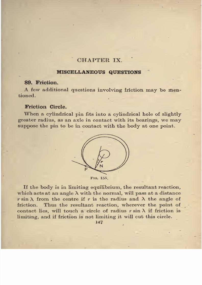
8/4/2019 Elementary Statics of 2 & Dimensions R.J.a. Barnard 1921
http://slidepdf.com/reader/full/elementary-statics-of-2-dimensions-rja-barnard-1921 159/272
CHAPTER IX.
MISCELLANEOUS QUESTIONS
89. Friction.
A few additional questions involving friction may be men-
tioned.
Friction Circle.
When a cylindrical pin fits into a cylindrical hole of slightly
greater radius, as an axle in contact with its bearings, we may
suppose the pin to be in contact with the body at one point.
Fig. 155.
If the body is in limiting equilibrium, the resultant reaction,
which acts at an angle X with the normal, will pass at a distance
r sin X from the centre if r is the radius and X the angle of
friction. Thus the resultant reaction, wherever the point of
contact lies, will touch a circle of radius r sin X if friction is
limiting, and if friction is not limiting it will cut this circle.
147
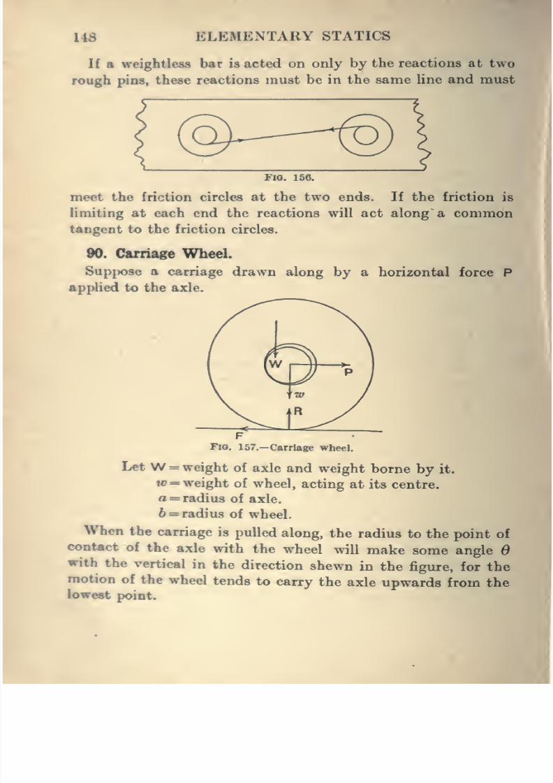
8/4/2019 Elementary Statics of 2 & Dimensions R.J.a. Barnard 1921
http://slidepdf.com/reader/full/elementary-statics-of-2-dimensions-rja-barnard-1921 160/272
148 ELEMENTARY STATICS
If a weightless bar is acted on only by the reactions at two
rough pins, these reactions must be in the same line and must
FIO. 156.
meet the friction circles at the two ends. If the friction is
limiting at each end the reactions will act along a commontangent to the friction circles.
90. Carriage Wheel.
Suppose a carriage drawn along by a horizontal force P
applied to the axle.
FFio. 157.—Carriage wheel.
Let W = weight of axle and weight borne by it.
w = weight of wheel, acting at its centre.
a = radius of axle.
6 = radius of wheel.
When the carriage is pulled along,the radius to the point of
contoct of the axle with the wheel will make some angle 6with the vertical in the direction shewn in the figure, for the
motion of the wheel tends to carry the axle upwards from the
lowest point.
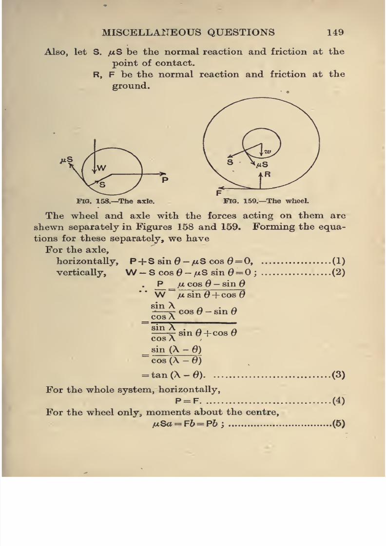
8/4/2019 Elementary Statics of 2 & Dimensions R.J.a. Barnard 1921
http://slidepdf.com/reader/full/elementary-statics-of-2-dimensions-rja-barnard-1921 161/272
MISCELLANEOUS QUESTIONS 149
Also, let S. yiiS be the normal reaction and friction at the
point of contact.
R, F be the normal reaction and friction at the
ground.
Fig. 158.—The axle. FiQ. 159.—The wheel.
The wheel and axle with the forces acting on them are
shewn separately in Figures 158 and 159. Forming the equa-
tions for these separately, we have
For the axle,
P+ S sin0-/xS cos 6 = 0,
W-Scos0-/xSsin0= O;
. P _fi cos - sin
W yitsin^+cos0
sin X
horizontally,
vertically,
(1)
.(2)
cosX
sin X
cos 6 -sin 6
sin0+cos0cos X
^8in(X-e
)
~cos(X-0j
= tan(X-0)
For the whole system, horizontally,
P = F
For the wheel only, moments about the centre,
/uSa = F6= P&;
(3)
(4)
.(5)
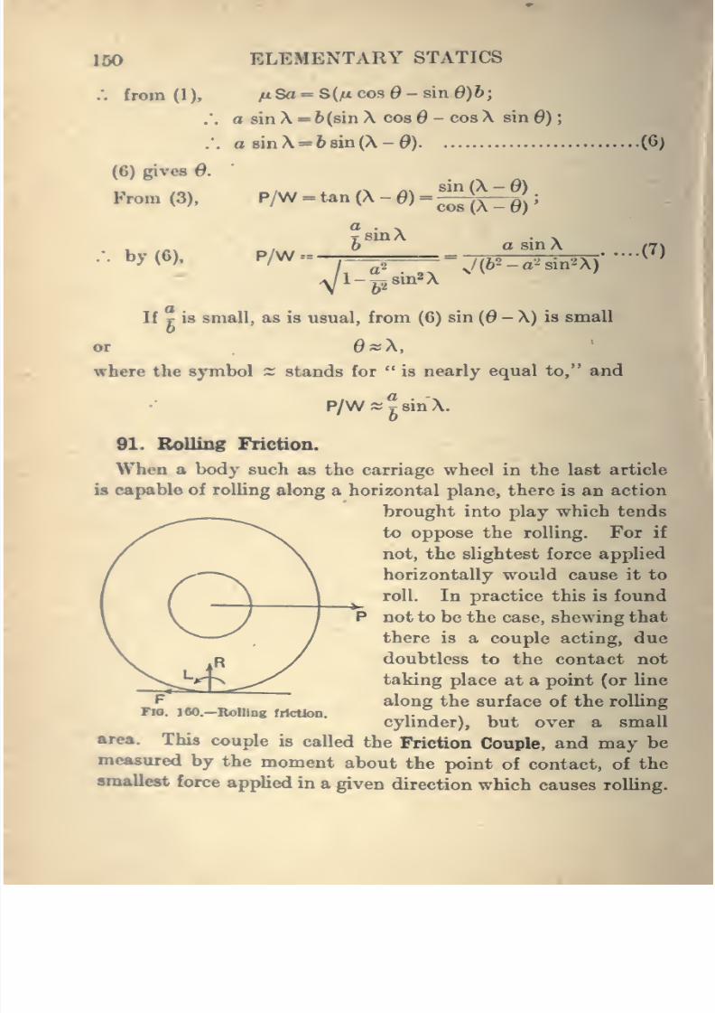
8/4/2019 Elementary Statics of 2 & Dimensions R.J.a. Barnard 1921
http://slidepdf.com/reader/full/elementary-statics-of-2-dimensions-rja-barnard-1921 162/272
150 ELEMENTARY STATICS
, from (1 ),
(6) gives d.
From (3),
. by (6),
/x Sa = S(ai cos - sin 0)6
a sin X = 6(8in X cos - cos X sin 6) ;
a 8inX = 68in(X-0) .(6)
P/W = tan(X-0) =
sinX
P/W-=-
sin (X - 6)
cos(X-0)'
a sinX
sin^X
\/(62-a'^sin2X)(7)
If r is small, as is usual, from (6) sin {6 - X) is small
or 0»X,
where the symbol s stands for " is nearly equal to," and
P/Ws^sinX.
91. Rolling Friction.
When a body such as the carriage wheel in the last article
b capable of rolling along a horizontal plane, there is an action
brought into play which tends
to oppose the rolling. For if
not, the slightest force applied
horizontally would cause it to
roll. In practice this is found
not to be the case, shewing that
there is a couple acting, due
doubtless to the contact not
taking place at a point (or line
along the surface of the rolling
cylinder), but over a small
area. This couple b called the Friction C!onple, and may be
measured by the moment about the point of contact, of the
smallest force applied in a given direction which causes rolling.
i
Tn. 100.—Rolling friction.
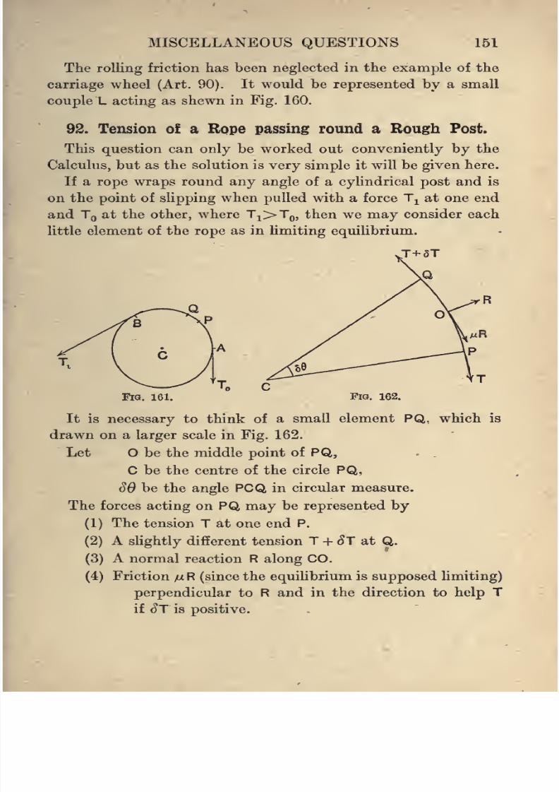
8/4/2019 Elementary Statics of 2 & Dimensions R.J.a. Barnard 1921
http://slidepdf.com/reader/full/elementary-statics-of-2-dimensions-rja-barnard-1921 163/272
MISCELLANEOUS QUESTIONS 151
The rolling friction has been neglected in the example of the
carriage wheel (Art. 90). It would be represented by a small
couple L acting as shewn in Fig. 160.
92. Tension of a Rope passing round a Rough Post.
This question can only be worked out conveniently by the
Calculus, but as the solution is very simple it will be given here.
If a rope wraps round any angle of a cylindrical post and is
on the point of slipping when pulled with a force Tj^ at one end
and Tg at the other, where Ti>To, then we may consider each
little element of the rope as in limiting equilibrium.
Fig. 161. Fig. 162.
It is necessary to think of a small element PQ, which is
drawn on a larger scale in Fig. 162.
Let O be the middle point of PQ, - .
C be the centre of the circle PQ,
S6 be the angle PCQ in circular measure.
The forces acting on PQ may be represented by
(1) The tension T at one end P.
(2) A slightly different tension T + ^T at Q.
(3) A normal reaction R along CO.
(4) Friction /x R (since the equilibrium is supposed limiting)
perpendicular to R and in the direction to help T
if St is positive.
8/4/2019 Elementary Statics of 2 & Dimensions R.J.a. Barnard 1921
http://slidepdf.com/reader/full/elementary-statics-of-2-dimensions-rja-barnard-1921 164/272
152 ELEMENTARY STATICS
The angles between the tensions and the friction will each
SBbe -S-; hence resolving along CO,
R = Tsin^ + (T+^T)sin^, (1)
and perpendicular to CO,
^R+TC0Sy = (T+^T)C0S^ (2)
T^. se sd
Now sin -K- ~ -Q-
and cos -H" ~ 1
if we neglect squares and products of small quantities.
Hence we get from (1),
and from (2), mR+T = J+ST;
:. R = TSe
and /xR = <5T;
• •
Y= ^°^'
.-. Jy=m0+c;
.-. log.T-log,To= ;tt0;
.•. \og,— =iJLe;
'o
• , .-. T = ToeM^
where T^ is the tension at A and 6 is the angle PCA.
In particular, if the rope wraps on an angle a (ACB) of the
post, , ^
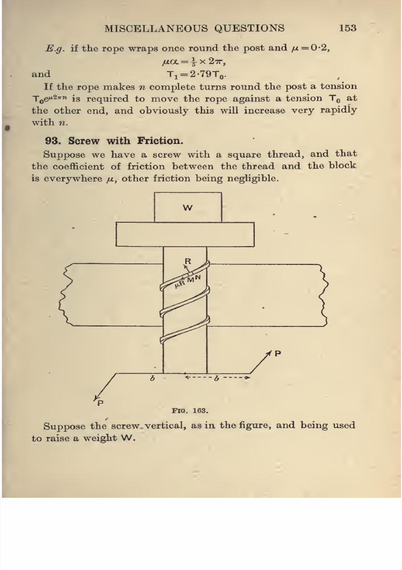
8/4/2019 Elementary Statics of 2 & Dimensions R.J.a. Barnard 1921
http://slidepdf.com/reader/full/elementary-statics-of-2-dimensions-rja-barnard-1921 165/272
MISCELLANEOUS QUESTIONS 153
E.g. if the rope wraps once round the post and fi = 0-2,
/«a = |x27r,
and Ti-2-79To.If the rope makes n complete turns round the post a tension
T^g^27rn is required to move the rope against a tension Tq at
the other end, and obviously this will increase very rapidly
with n.
93. Screw with Friction.
Suppose we have a screw with a square thread, and that
the coefficient of friction between the thread and the block
is everywhere ju, other friction being negligible.
W
^ 3 ^
Fig. 163,
Suppose the screw vertical, as in the figure, and being used
to raise a weight W.
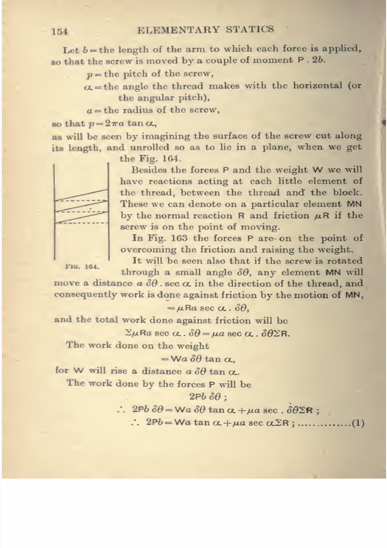
8/4/2019 Elementary Statics of 2 & Dimensions R.J.a. Barnard 1921
http://slidepdf.com/reader/full/elementary-statics-of-2-dimensions-rja-barnard-1921 166/272
154 ELEMENTARY STATICS
Let 6 « the length of the arm to which each force is applied,
80 that the screw is moved by a couple of moment P . 26.
p = the pitch of the screw,
a=the angle the thread makes with the horizontal (or
the angular pitch),
a=the radius of the screw,
so that p= 27ra tan tt,
as will be seen by imagining the surface of the screw cut along
its length, and unrolled so as to lie in a plane, when we getthe Fig. 164.
Besides the forces P and the weight W we will
have reactions acting at each little element of
the thread, between the thread and the block.
These we can denote on a particular element MN
by the normal reaction R and friction yu R if the
screw is on the point of moving.
In Fig. 163 the forces P are on the point of
overcoming the friction and raising the weight.
It will be seen also that if the screw is rotated
through a small angle SO, any element MN will
move a distance a SS . sec a in the direction of the thread, and
consequently work is done against friction by the motion of MN,
= /xRaseca. SO,
and the total work done against friction will be
IfiRa sec a. . SO = fia aec a. . SO^R.
The work done on the weight
= >Afa SO t&n OL,
for W will rise a distance a SO tan a.
The work done by the forces P will be
2P6 SO
:. 2P6 so =Wa SO tana +/za sec . SG2R;
:. 2P6=Wa tan a +yua sec oc2R; (1)
FIO. 164.
8/4/2019 Elementary Statics of 2 & Dimensions R.J.a. Barnard 1921
http://slidepdf.com/reader/full/elementary-statics-of-2-dimensions-rja-barnard-1921 167/272
MISCELLANEOUS QUESTIONS 155
also, if we resolve the forces-parallel to the axis of the screw,
we get
W+2yuR sin a = 2R cos a;
.*. W = 2R (-yu sin a+cos a)
= ( -/^ sin a+cos a.)2R ; (2)
.'. by (1) and (2),
ina sec ocW2p6 = Wa tan a
=WaI
tan a. -
=Wa
=Wa
lut. sin oc - cos CL
JUL sec OL
fi sm OL - cos oc/
sin oc (yu sin oc - cos oc ) - yu
cos OL {jUL sin a - cos a)
fjL cos^oc +sin oc cos oc
cos OL (cos oc - yu sin oc)
yti cos a+sin oc
cos oc - yu sin aIf X is the angle of friction, this can be written
sin \• ^ . cos oc+sin oc
c-1 ... cos A
sm A .
cos oc =r . sin occos A
^^^ sin(X+a)cos (A + a)
= Watan (X+a).
W 26 ,, .,-— =— cot (a+A).PaIf A is less than a and the screw is on the point of running
back, being just held by forces P' at the ends of the arm,
W 26 ., ..
p>- =— cot(a-A).
If A is greater than oc, no weight, however large, can cause
the screw to run back.
8/4/2019 Elementary Statics of 2 & Dimensions R.J.a. Barnard 1921
http://slidepdf.com/reader/full/elementary-statics-of-2-dimensions-rja-barnard-1921 168/272
156 ELEMENTARY STATICS
94. Asiatics.
If a system of forces acting at given points in a body are in
equilibrium, and the body is rotated through any angle abouta fixed point, while the forces continue to act at the same
points and in the same directions, the forces will not in general
remain in equilibrium. For example, a magnet may be thought
of as acted on by two equal and opposite forces at its two
poles, which remain unchanged in magnitude and direction in
whatever position the magnet is placed. If the magnet is
capable of rotation about a vertical axis only, it will be in
equilibrium when its direction coincides with the direction
of the magnetic forces, and if rotated from this position and
released it will not be in equilibrium, but will begin to move
towards the equilibrium position.
If the forces acting as above on a body are still in equilibrium
when the body is turned through any angle about a fixed
point, they are said to be in Astatic Equilibrium. Such a case
occurs when twa magnets of equal length and strength are
connected so as to be parallel to one another, but with their
poles in opposite directions. The magnets form an astatic
combination.
Suppose that any forces whose components are Xj, Y^
X,, Yj-, etc., act at points whose coordinates referred to apoint O in the body are x^, y^ ; x^, y^ ; etc., and we wish to
discover whether any rotation of the body about O, while the
forces act at the same points in the body and in the same
directions in space, will cause the body to be in a state of
equilibrium, and if this is the case to find whether more than
one such position of equilibrium exists, and what condi-
tions are necessary that all such positions are positions of
equilibrium.
First examine the effect of a rotation about O on a single
force. The components of the force remain unchanged, but
the point of application changes from P to P' in Fig. 166.
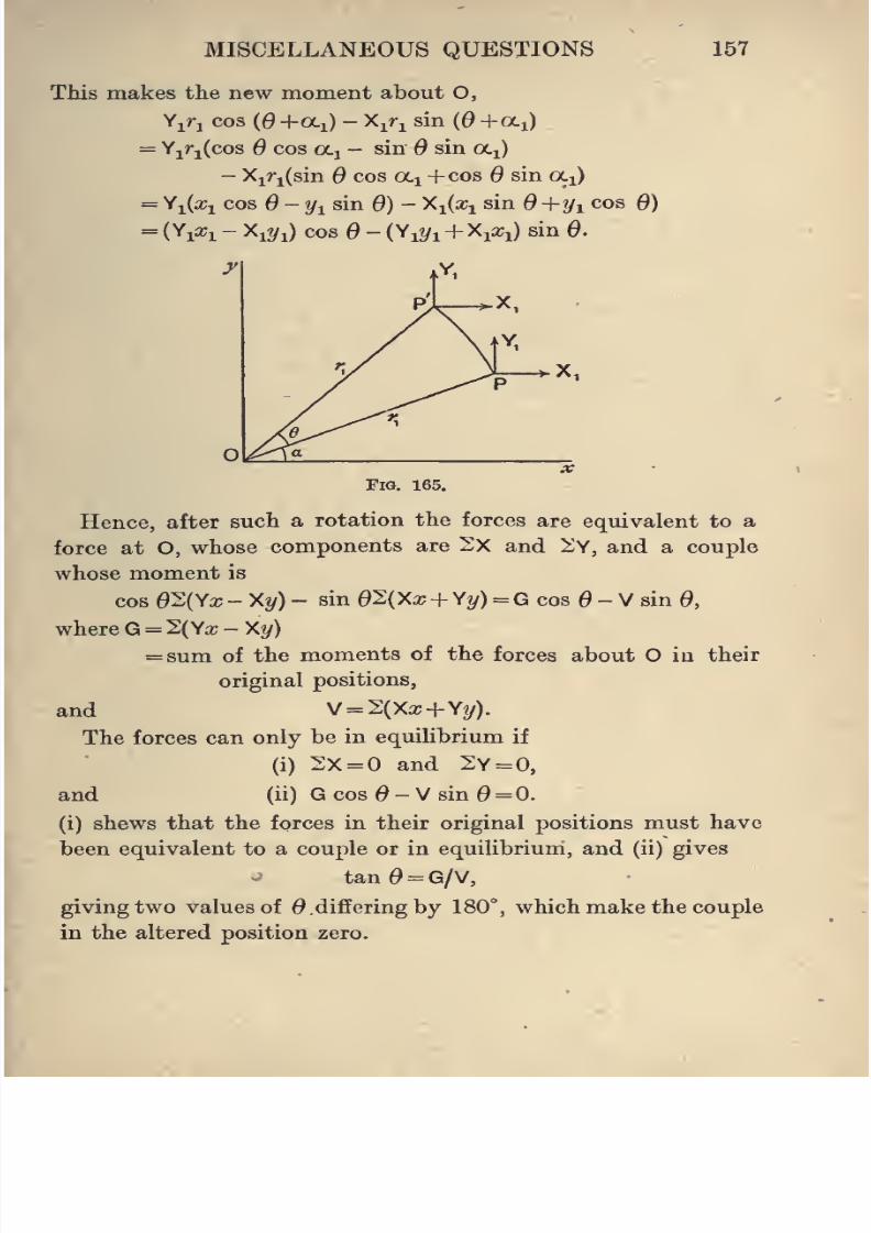
8/4/2019 Elementary Statics of 2 & Dimensions R.J.a. Barnard 1921
http://slidepdf.com/reader/full/elementary-statics-of-2-dimensions-rja-barnard-1921 169/272
MISCELLANEOUS QUESTIONS
This makes the new moment about O,
Y^ri cos {0 +ai) - X^r^ sin {6 +oii)
= Yjrj{coa cos ocj - sin sin a^)
- Xiri(sin cos oci +cos d sin oCi)
= Yi(a;i cos 0-yi sin 6) - Y-iix^ sin 6+yi cos 0)
= (Yia;i - Xi?/i) cos - ( Yi?/i + Xi^i) sin 0.
157
Fig. 165.
Hence, after such a rotation the forces are equivalent to a
force at O, whose components are 2X and ^Y, and a couple
whose moment is
cos 02(Ya; - Xy) - sin 02(Xx + Y?/) = G cos - V sin 0,
where G = 2(Ya;-X^)
= sum of the moments of the forces about O in their
original positions,
and V = 2(Xx+Yy).
The forces can only be in equiUbrium if
(i) 2X=0 and 2y = 0,
and (ii) G cos - V sin = 0.
(i) shews that the forces in their original positions must have
been equivalent to a couple or in equilibrium, and (ii) gives
tan0 = G/V,
giving two values of 0, differing by 180°, which make the couple
in the altered position zero.
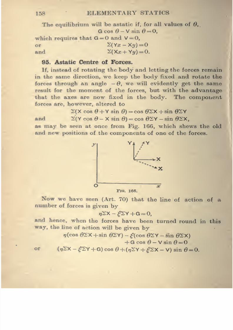
8/4/2019 Elementary Statics of 2 & Dimensions R.J.a. Barnard 1921
http://slidepdf.com/reader/full/elementary-statics-of-2-dimensions-rja-barnard-1921 170/272
158 ELEMENTARY STATICS
The equilibrium will be astatic if, for all values of Q,
Gcos0-V8inO = O,
which requires that G = and V = 0,
or 2(Y2-X«/)=0
and 2;(Xx+Yy)=0.
95. Astatic Centre of Forces.
If, instead of rotating the body and letting the forces remain
in the same direction, we keep the body fixed and rotate the
forces through an angle -d, we will evidently get the same
result for the moment of the forces, but with the advantage
that the axes are now fixed in the body. The component
forces are, however, altered to
2(X cos +Y sin 0) =cos 02X +sin 02
and 2:(Y cos - X sin S) = cos 02Y - sin 02:x,
9A may be seen at once from Fig. 166, which shews the old
and new positions of the components of one of the forces.
Xrr -vX
-^x
O XFlO. 166.
Now we have seen (Art. 70) that the line of action of a
oomber of forces is given by
i72X-^Y+G = 0,
and hence, when the forces have been turned round in this
way, the line of action will be given by
i;(cos e2X +sin 02Y) - ^(cos 02Y - sin 02X)
+Gco8 0-VsinO= Oor («;2:X-^y+G)cos 0+(.72Y+^2X - V) sin = 0.
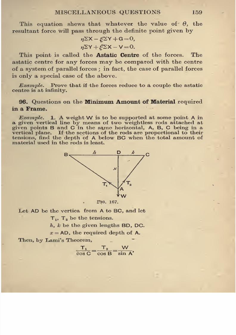
8/4/2019 Elementary Statics of 2 & Dimensions R.J.a. Barnard 1921
http://slidepdf.com/reader/full/elementary-statics-of-2-dimensions-rja-barnard-1921 171/272
MISCELLANEOUS QUESTIONS 159
This equation shews that whatever the value of 6, the
resultant force will pass through the definite point given by
^2X-f2Y +G=0,
This point is called the Astatic Centre of the forces. The
astatic centre for any forces may be compared with the centre
of a system of parallel forces ; in fact, the case of parallel forces
is only a special case of the above.
Example. Prove that if the forces reduce to a couple the astatic
centre is at infinity.
96. Questions on the Minimum Amount of Material required
in a Frame.
Example. 1. A weightW is to be supported at some point A in
a given vertical line by means of two weightless rods attached at
given points B and C in the s^me horizontal, A, B, C being in a
vertical plane. If the sections of the rods are proportional to their
tensions, find the depth of A below BC when the total amount of
material used in the rods is least.
ZTiG. 167.
Let AD be the vertica from A to BC, and let
Ti, T2 be the tensions.
h, k be the given lengths BD, DC.
x = AD, the required depth of A.
Then, by Lami's Theorem,
Tx ^ T, ^ Wcos C cos B sin A'
8/4/2019 Elementary Statics of 2 & Dimensions R.J.a. Barnard 1921
http://slidepdf.com/reader/full/elementary-statics-of-2-dimensions-rja-barnard-1921 172/272
160 ELEMENTARY STATICS
and if the croes sections are mTi and toT„ the volume of material
"«^» mJ,c+mTj>
= -.— . (c cos C + cos B)
Bin A
Bin A (.6 c }
=mW
be sin A
x{h + k)
x*+hk
=mW( ^*^<-">and this is a minimum when x*=hk, or the angle BAC is a
right angle.
2. A weightW is to be supported at A by two rods fixed to two
points B, C, in the same vertical. If AB is horizontal and of given
length h, find the length of C A so that the least quantity of material
may be required for the two rods, assuming the sections proportional
to the stresses in the rods and the weights of the rods themselves
neglected.
If the section for a tension is made r times the section for a thrust
of the same magnitude, find the length of CA for the minimumquantity of material.
8. A horizontal bar AB, loswled in any way, is hinged at A andsupported by a weightless strut CD jointed to a point C vertically
below A and to a point in the rod. Shew that if the section of CDis proportional to the thrust in it, the quantity of material in it will
depend only on the inclination of CD to the vertical, not on its length,and will be least when the strut makes an angle 45° with the vertical.
EXABIPLES. -
L A weightW is raised by a string passing round a pulley turningon a rough axle. If P is the force exerted and the radius of the axle
is 6, and that of the wheel is a, and the angle of friction is A, provethat
W a -0 sin A
P a + 6 sin A'
2. In a rough screw verify that the work done by the appliedforce is the sum of the works done against the opposing force and•gainst friction.
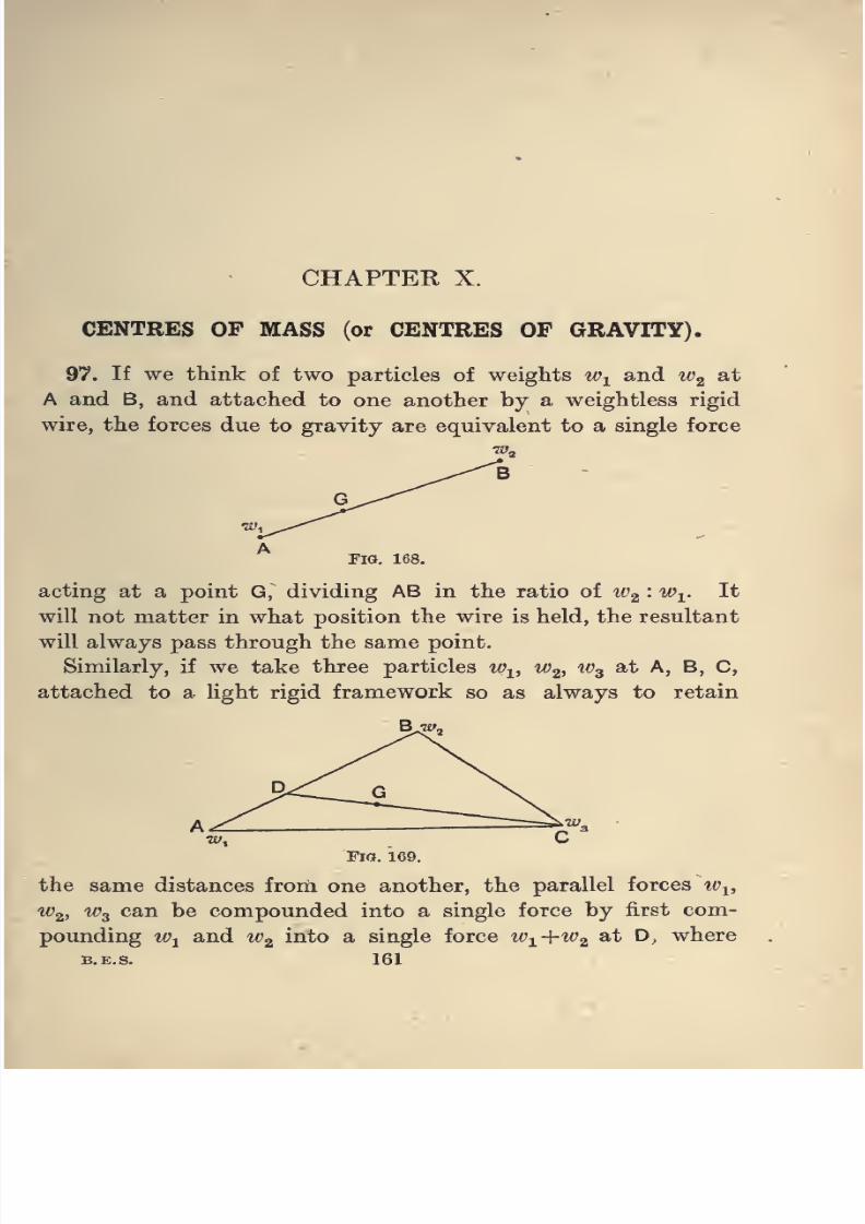
8/4/2019 Elementary Statics of 2 & Dimensions R.J.a. Barnard 1921
http://slidepdf.com/reader/full/elementary-statics-of-2-dimensions-rja-barnard-1921 173/272
CHAPTER X.
CENTRES OF MASS (or CENTRES OP GRAVITY).
97. If we think of two particles of weights w^ and Wg ^^
A and B, and attached to one another by a weightless rigid
wire, the forces due to gravity are equivalent to a single force
Fig. 168.
acting at a point G, dividing AB in the ratio of Wg •*^i-
I^
will not matter in what position the wire is held, the resultant
will always pass through the same point.
Similarly, if we take three particles w^, w^, w^ at A, B, C,
attached to a light rigid framework so as always to retain
Bjzw,
Fig. 169.
the same distances from one another, the parallel forces w^,
Wg. "Wa can be compounded into a single force by first com-
pounding Wy and Wg ^^^ ^ single force w-^+w.2, ^^ '-*• where
B.E.S. 161
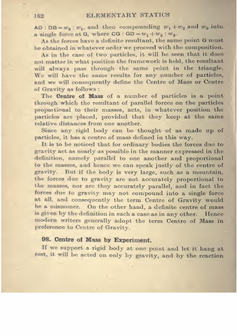
8/4/2019 Elementary Statics of 2 & Dimensions R.J.a. Barnard 1921
http://slidepdf.com/reader/full/elementary-statics-of-2-dimensions-rja-barnard-1921 174/272
162 ELEMENTARY STATICS
AD : DB-w, : ir,, and then compounding w^+w^, and tv^ into.
A single force at G, where CO : GD = w^ +W2 : H'3.
As the forces have a definite resultant, the same point G must
be obtained in whatever order we proceed with the composition.
As in the case of two particles, it will be seen that it does
not matter in what position the framework is held, the resultant
will always pass through the same point in the triangle.
We will have the same results for any number of particles,
and we will consequently define the Centre of Mass or Centre
of Gravityas follows :
The Centre of Blass of a number of particles is a point
through which the resultant of parallel forces on the particles
propoitiooal to their masses, acts, in whatever position the
particles are placed, provided that they keep at the same
relative distances from one another.
Since any rigid body can be thought of as made up of
particles, it has a centre of mass defined in this way.
It is to be noticed that for ordinary bodies the forces due to
gravity act as nearly as possible in the manner expressed in the
definition, namely parallel to one another and proportional
to the masses, and hence we can speak justly of the centre of
gravity. But if the body is very large, such as a mountain,
the forces due to gravity are not accurately proportional to
the masses, nor are they accurately parallel, and in fact the
forces due to gravity may not compound into a single force
at all, and consequently the term Centre of Gravity would
be a misnomer. On the other hand, a definite centre of mass
is given by the definition in such a case as in any other. Hence
modem writers generally adopt the term Centre of Mass in
preference to Centre of Gravity.
98. Centre of Mass by Experiment.
If we support a rigid body at one point and let it hang at
rest, it will be acted on only by gravity, and by the reaction
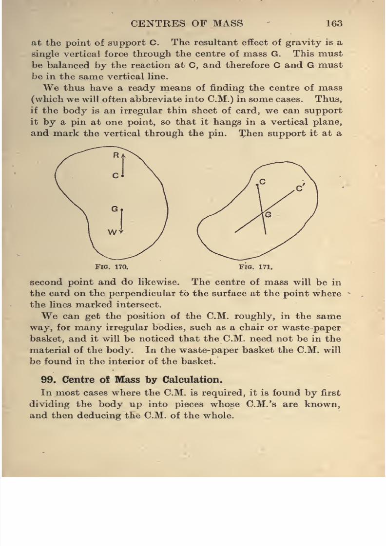
8/4/2019 Elementary Statics of 2 & Dimensions R.J.a. Barnard 1921
http://slidepdf.com/reader/full/elementary-statics-of-2-dimensions-rja-barnard-1921 175/272
CENTRES OF MASS 163
at the point of support C. The resultant effect of gravity is a
single vertical force through the centre of mass G. This must
be balanced by the reaction at C, and therefore C and G must
be in the same vertical line.
We thus have a ready means of finding the centre of mass
(which we will often abbreviate into CM.) in some cases. Thus,
if the body is an irregular thin sheet of card, we can support
it by a pin at one point, so that it hangs in a vertical plane,
and mark the vertical through the pin. Xhen support it at a
FlO. 170. Fig. 171.
second point and do hkewise. The centre of mass will be in
the card on the perpendicular to the surface at the point where
the lines marked intersect.
We can get the position of the CM. roughly, in the same
way, for many irregular bodies, such as a chair or waste-paper
basket, and it will be noticed that the CM. need not be in the
material of the body. In the waste-paper basket the CM. will
be found in the interior of the basket.
99. Centre o£ Iilass by Calculation.
In most cases where the CM. is required, it is found by first
dividing the body up into pieces whose C.M.'s are known,
and then deducing the CM. of the whole.
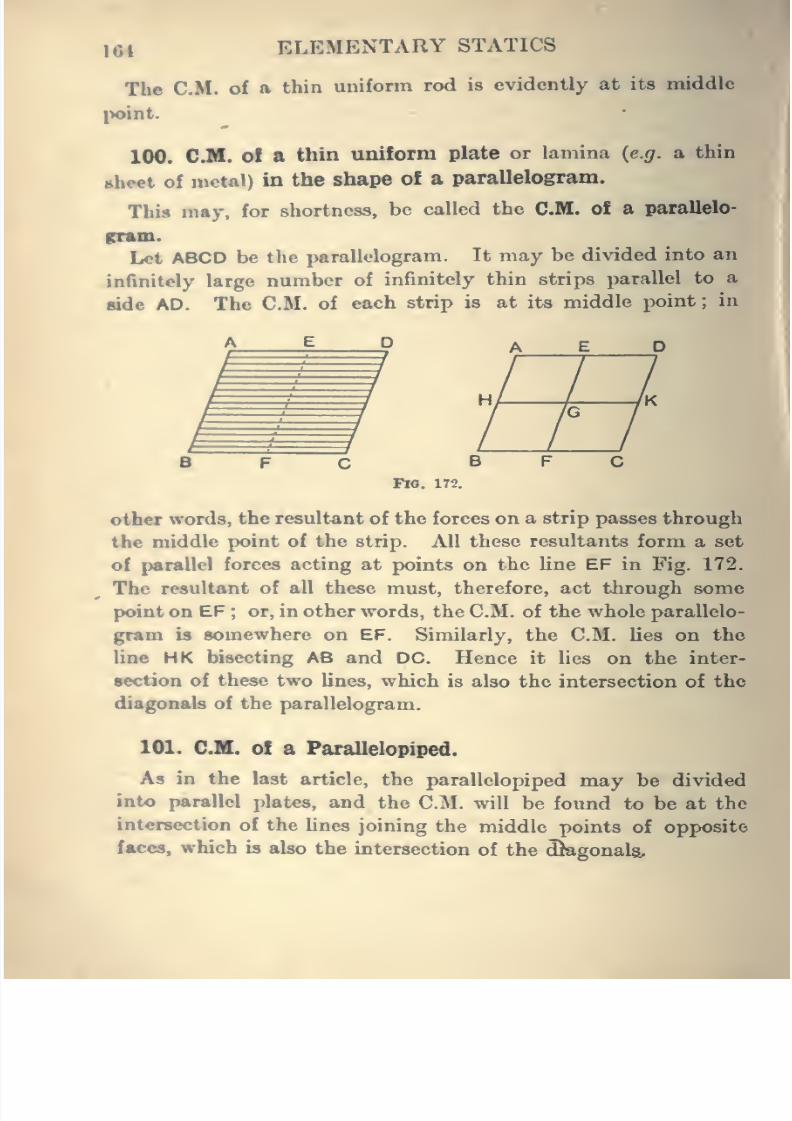
8/4/2019 Elementary Statics of 2 & Dimensions R.J.a. Barnard 1921
http://slidepdf.com/reader/full/elementary-statics-of-2-dimensions-rja-barnard-1921 176/272
164 ELEMENTARY STATICS
The CM. of a thin uniform rod is evidently at its middle
point.
100. CM. ol a thin uniform plate or lamina {e.g. a thin
sheet of metal) in the shape of a parallelogram.
This may, for shortness, be called the CM. of a parallelo-
fnun.
Let ABCD be the parallelogram. It may be divided into an
infinitely large number of infinitely thin strips parallel to a
side AD. The CM. of each strip is at its middle point;
in
II
other words, the resultant of the forces on a strip passes through
the middle point of the strip. All these resultants form a set
of parallel forces acting at points on the line EF in Fig. 172.
The resultant of all these must, therefore, act through some
point on EF; or, in other words, the CM. of the whole parallelo-
gram is somewhere on EF. Similarly, the CM. lies on the
line HK bisecting AB and DC. Hence it lies on the inter-
section of these two lines, which is also the intersection of the
diagonab of the parallelogram.
101. CM, of a Parallelopiped.
As in the last article, the parallelopiped may be divided
into parallel plates, and the CM. will be found to be at the
intersection of the Unes joining the middle points of opposite
faces, which is also the intersection of the dkgonala.
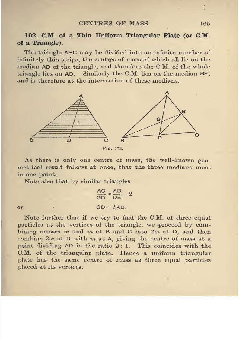
8/4/2019 Elementary Statics of 2 & Dimensions R.J.a. Barnard 1921
http://slidepdf.com/reader/full/elementary-statics-of-2-dimensions-rja-barnard-1921 177/272
CENTRES OF MASS 165
102. CM. of a Thin Uniform Triangular Plate (or CM.
of a Triangle).
The triangle ABC may be divided into an infinite number of
infinitely thin strips, the centr,es of mass of which all lie on the
median AD of the triangle, and therefore the CM. of the whole
triangle lies on AD. Similarly the CM. lies on the median BE,
and is therefore at the intersection of these medians.
As there is only one centre of mass, the well-known geo-
metrical result follows at once, that the three medians meet
in one point.
Note also that by similar triangles
AG AB „
GD DE
or - GD=1AD.
Note further that if we try to find the CM. of three equal
particles at the vertices of the triangle, we .proceed by com-
bining masses m and m at B and into 2m at D, and thencombine 2m at D with m at A, giving the centre of mass at a
point dividing AD in the ratio 2:1. This coincides with the
CM. of the triangular plate. Hence a uniform triangular
plate has the same centre of mass as three equal particles
placed at its vertices.
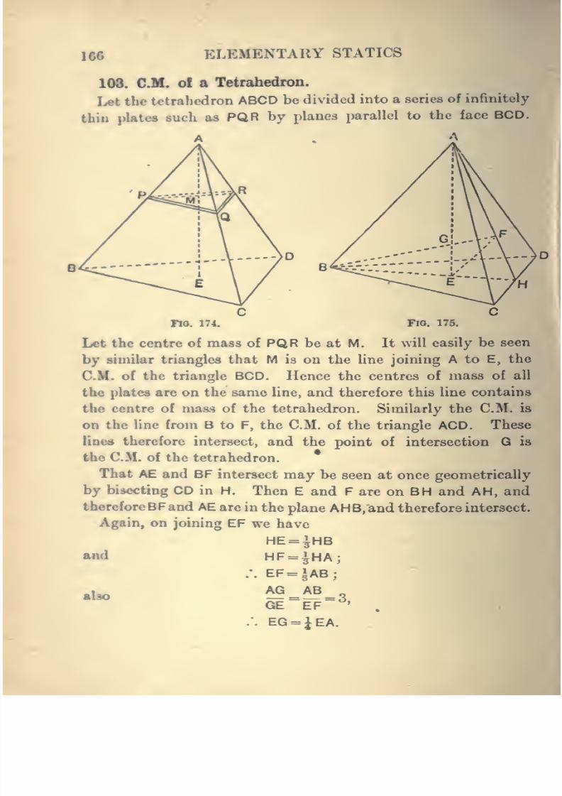
8/4/2019 Elementary Statics of 2 & Dimensions R.J.a. Barnard 1921
http://slidepdf.com/reader/full/elementary-statics-of-2-dimensions-rja-barnard-1921 178/272
166 ELEMENTARY STATICS
103. CM. of a Tetrahedron.
Let the tt'trahedron ABCD be divided into a series of infinitely
thin platea such as PQR by planes parallel to the face BCD.
A A
C C
Fio.174. Fio. 175.
Let the centre of mass of PQR be at M. It will easily be seen
by similar triangles that M is on the line joining A to E, the
CM. of the triangle BCD. Hence the centres of mass of all
the plates are on the same line, and therefore this line contains
the centre of mass of the tetrahedron. Similarly the CM. is
on the line from B to F, the CM. of the triangle ACD. These
lines therefore intersect, and the point of intersection G is
the CM. of the tetrahedron.
That AE and BF intersect may be seen at once geometrically
by bisecting CD in H. Then E and F are on BH and AH, and
thereforeBFand AE are in the plane AHB,and therefore intersect.
Again, on joining EF we have
HE=^HBand HF= ^HA;
.-. EF = JAB;
also ^=^ = 3GE EF ' .
.". EG = JEA.
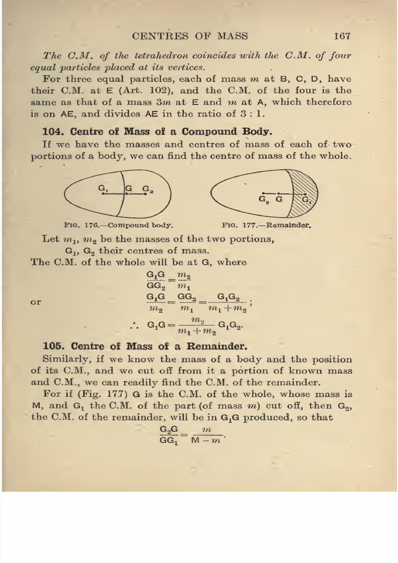
8/4/2019 Elementary Statics of 2 & Dimensions R.J.a. Barnard 1921
http://slidepdf.com/reader/full/elementary-statics-of-2-dimensions-rja-barnard-1921 179/272
CENTRES OF MASS 167
The CM. of the tetrahedron coincides with the CM. of four
equal particles placed at its vertices.
For three equal particles, each of mass m at B, C, D, have
their CM. at E (Art. 102), and the CM. of the four is the
same as that of a mass 3m at E and m at A, which therefore
is on AE, and divides AE in the ratio of 3 : 1.
104. Centre of Mass of a Compound Body.
If we have the masses and centres of mass of each of two
portions of a body, we can find the centre of mass of the whole.
Fia. 176.—Compound body. Fig. 177.—Remainder.
Let nil, "^2 ^® ^^^ masses of the two portions,
Gj, Gg their centres of mass.
The CM. of the whole will be at G, where
G^G _ mg
GGg m^
orG^G ^ GGa ^ GiGa
.
ni^ nil in-i+m^'
^ nii+m^ ^''
105. Centre of Mass of a Remainder.
Similarly, if we know the mass of a body and the position
of its CM., and we cut off from it a portion of known mass
and CM., we can readily find the CM. of the remainder.
For if (Fig. 17.7) G is the CM. of the whole, whose mass is
M, and G^ the CM. of the part (of mass m) cut ofi, then G2,
the CM. of the remainder, will be in G^G produced, so that
G2G_ mGGi
~ M - m
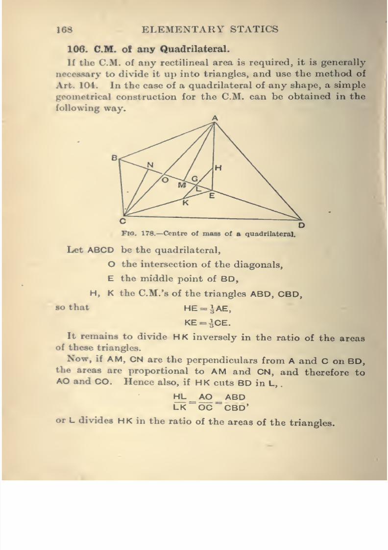
8/4/2019 Elementary Statics of 2 & Dimensions R.J.a. Barnard 1921
http://slidepdf.com/reader/full/elementary-statics-of-2-dimensions-rja-barnard-1921 180/272
168 ELEMENTARY STATICS
106. CM. ol any Quadrilateral.
If the CM. of any rectilineal area is required, it is generally
necessary to divide it up into triangles, and use the method of
Art. 104. In the case of a quadrilateral of any shape, a simple
geometrical construction for the CM. can be obtained in the
following way.
A
^no. 178.—Centre of mass of a quadrilateral.
Let ABCD be the quadrilateral,
O the intersection of the diagonals,
E the middle point of BD,
H, K the CM.'s of the triangles ABD, CBD,
so that HE = ^AE,
KE = ^CE.
It remains to divide HK inversely in the ratio of the areas
of these triangles.
Now, if AM, CN are the perpendiculars from A and C on BD,
the areas are proportional to AM and CN, and therefore to
AO and CO. Hence also, if H K cuts BD in L,
.
HL^AO^ABDLK~OC~CBD'
or L divides HK in the ratio of the areas of the triangles.
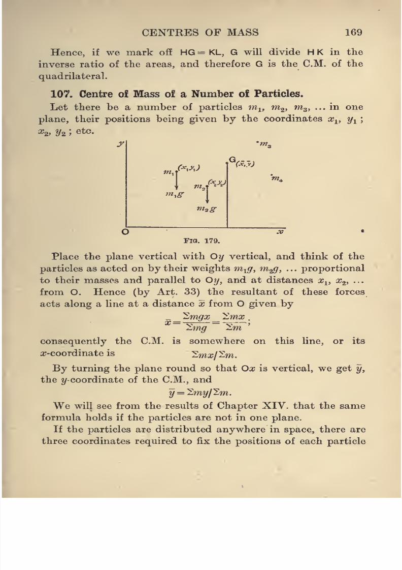
8/4/2019 Elementary Statics of 2 & Dimensions R.J.a. Barnard 1921
http://slidepdf.com/reader/full/elementary-statics-of-2-dimensions-rja-barnard-1921 181/272
CENTRES OF MASS 169
Hence, if we mark off HG = KL, G will divide H K in the
inverse ratio of the areas, and therefore G is the CM. of the
quadrilateral.
107. Centre of Mass of a Number of Particles.
Let there be a number of particles m^, m^, m^, ... in one
plane, their positions being given by the coordinates x^,2/1
^2' !/2 '^^^'
/•^.^'J
'''i
m^g
G,--,
Fig. 179.
Place the plane vertical with Oy vertical, and think of the
particles as acted on by their weights m-^g, m^, . . . proportional
to their masses and parallel to Oij, and at distances aj^, x^, •••
from O. Hence (by Art. 33) the resultant of these forces
acts along a line at a distance x from O given by
_ _ "^rngx _ Imx .
2.mg 2,m
consequently the CM. is somewhere on this line, or its
a;-coordinate is 'Emx/'^m.
By turning the plane round so that Ox is vertical, we get y,
the ^/-coordinate of the CM., and
y = 'Emy/'^m.
We will see from the results of Chapter XIV. that the same
formula holds if the particles are not in one plane.
If the particles are distributed anywhere in space, there are
three coordinates required to fix the positions of each particle
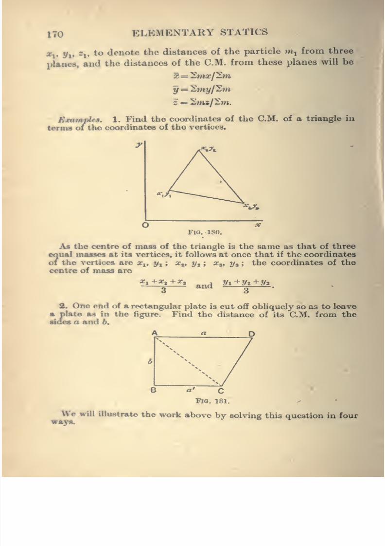
8/4/2019 Elementary Statics of 2 & Dimensions R.J.a. Barnard 1921
http://slidepdf.com/reader/full/elementary-statics-of-2-dimensions-rja-barnard-1921 182/272
170 ELEMENTARY STATICS
X,, y,, jj, to denote the distances of the particle mj from three
planes, and the distances of the CM. from these planes will be
X = '2mxl^m
ExampUa. 1. Find the coordinates of the CM. of a triangle in
terms of the coordinates of the vertices.
?Vt.
%*./.
FlO. ISO.
Aa the centre of mass of the triangle is the same as that of three
Sual maww at its vertices, it follows at once that if the coordinates
the vertices are x^, y^ ; Xj, y^ ; z,, y, ; the coordinates of the
centre of mass are
X, +x. +x.and
yi+Vi+y*
2. One end of a rectangular plate is cut off obliquely so as to leave
ft plate as in the figure. Find the distance of its CM. from the
MBS a and 6.
B fl' C
Fio. 181.
We will illustrate the work above by solving this question in fourways.
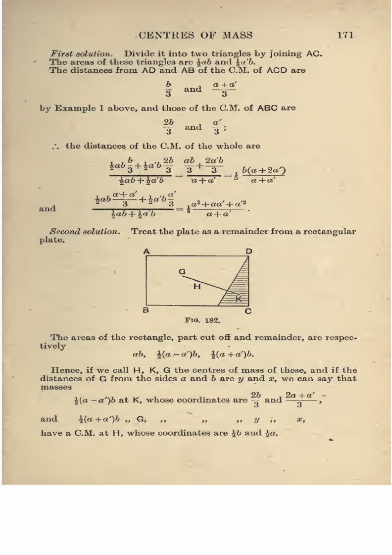
8/4/2019 Elementary Statics of 2 & Dimensions R.J.a. Barnard 1921
http://slidepdf.com/reader/full/elementary-statics-of-2-dimensions-rja-barnard-1921 183/272
CENTRES OF MASS 171
First solution. Divide it into two triangles by joining AC.
The areas of these triangles are ^ab and ^a'b.
The distances from AD and AB of the CM. of ACD are
b , a +a'
3 ^^^ -3-
by Example 1 above, and those of the CM. of ABC are
26 , a'-3- and 3;
.•. the distances of the CM. of the whole are
ia63 + ia6-3 -^ + -j-^,(^+ 2a0
^ab+ ^a'b a + a' ^ a + a'
and
^ao—;^r hfa b-
lab + ia'b a+ a'
Second solution. Treat the plate as a remainder from a rectangular
plate.
A D
Fig. 182.
The areas of the rectangle, part cut off and remainder, are respec-
tively
ab, l{a^a')b, l{a+a')b.
Hence, if we call H, K, G the centres of mass of these, and if the
distances of G from the sides a and b are y and x, we can say thatmasses
l{a -a')b at K, whose coordinates are „ and —^^>
and ^{a+a')b „ G, ,, ,, ,, y ;, x,
have a CM. at H, whose coordinates are ^b and |a.
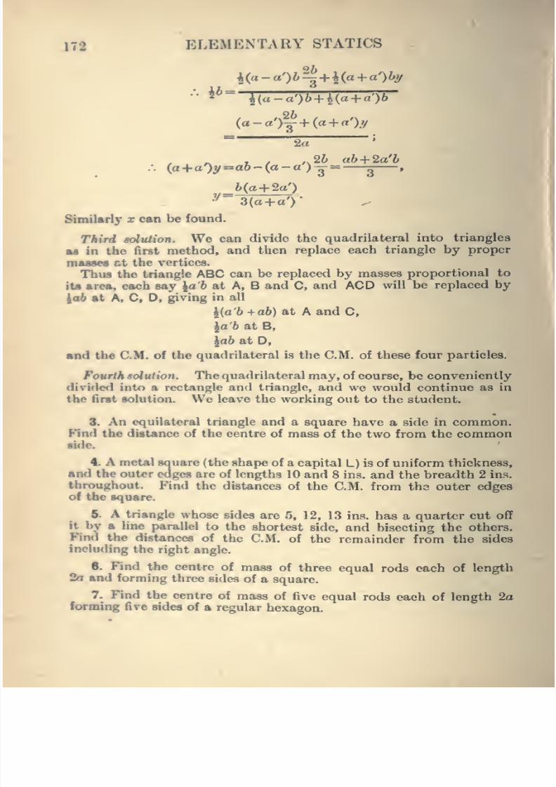
8/4/2019 Elementary Statics of 2 & Dimensions R.J.a. Barnard 1921
http://slidepdf.com/reader/full/elementary-statics-of-2-dimensions-rja-barnard-1921 184/272
172 ELEMENTARY STATICS
"^
2a'
. , ,,26 ah+ 2a'b:. (a+aOy-aft-Ca-a) g= g ,
b(a+ 2a')
y~ 3(a+ a')
SimiUrly x can be found.
Tkird aolution. We can divide the quadrilateral into triangles
M in the first method, and then replace each triangle by proper
mt—en ct the vertices.
Thiu the triangle ABC can be replaced by masses proportional to
tt« area, each say \a'b at A, B and C, and ACD will be replaced by
iab at A. C, D, giving in all
|(a'6 +a&) at A and C,
^a'b at B,
lab at D,
and the CM. of the quadrilateral is the CM. of these four particles.
Fourth solution. The quadrilateral may, of course, be conveniently
divided into a rectangle and triangle, and we would continue as in
the first solution. We leave the working out to the student.
8. An equilateral triangle and a square have a side in common.
Find the distance of the centre of mass of the two from the commonside.
4. A metal square (the shape of a capital L) is of uniform thickness,
and the outer edges are of lengths 10 and 8 ins. and the breadth 2 ias.
throoghout. Find the distances of the CM. from the outer edges
of the square.
ft. A triangle whose sides are 5, 12, 13 ins. has a quarter cut off
it bv a line parallel to the shortest side, and bisecting the others.
Find the distances of the CM. of the remainder from the sidesincluding the right angle.
6. Find the centre of mass of three equal rods each of length
2a and forming three sides of a square.
7. Find the centre of mass of five equal rods each of length 2aforming five sides of a regular hexagon.
8/4/2019 Elementary Statics of 2 & Dimensions R.J.a. Barnard 1921
http://slidepdf.com/reader/full/elementary-statics-of-2-dimensions-rja-barnard-1921 185/272
CENTRES OF MASS 173
8. ABCDEF is a hexagonal plate whose centre is O ; find the
CM. of the remainder after
(i) the triangle ABC has been removed,
(ii) the triangle OAB has been removed.
9. Find the distance of the CM. of a regular tetrahedron of
edge 2a from its base.
10. From a regular tetrahedron of edge 2a a regular tetrahedron
of edge a is cut off by a plane parallel to one face ; find the distance
of the CM. of the remainder from the base.
11. A cylindrical shell of thin sheet metal has a base of the same
thickness but no top. If its radius is r and height h, find the CM.
of the whole.
12. Find the position of the CM. of a framework of six equal
bars of length 2a forming the edges of a regular tetrahedron,
13. Find the CM. of a regular tetrahedron formed of thin sheet
metal.
14. Find the centre of mass of a hollow cone with a base, all
formed of uniform sheet metal.
15. One end of a rectangular plate is cut off obliquely, leaving a
quadrilateral whose parallel sides are of lengths 6 and 4 ins. and
breadth 3 ins. Find the distances of the CM. from the square end
and from the parallel sides.
16. In a cubical block a cylindrical hole is drilled perpendicular
to one face, the centre of one end of the cylinder being at the centre
of the cube. Find the CM. of the remainder if the edge of the cube
is 2a and the radius of the cylinder r.
17. In a circular sheet of metal of radius 10 ins., a circular hole
of radius 3 ins. is punched whose centre is 5 ins. from the centre ofthe sheet. Find the position of the CM. of the remainder.
18. Masses of 1, 2, 3, 4 lbs. are placed at the corners of a square
plate of mass 6 lbs. Find the centre of mass of the whole.
19. Masses of 1, 4, 3, 5 lbs. are placed at the corners of a square
plate of mass 6 lbs. Find the distance of the centre of mass of the
whole from the centre of the plate.
20. Masses 1, 2, 3, 4, 5, 6 are placed at equal intervals round the
circumference of a circular plate weighing 4 lbs. Find the CM. ofthe whole.
21. Two angles A, C of a quadrilateral are at distances h^, h^,
h h
from the diagonal BD. Shew that the CM. is at a distance'~
^
from BD.
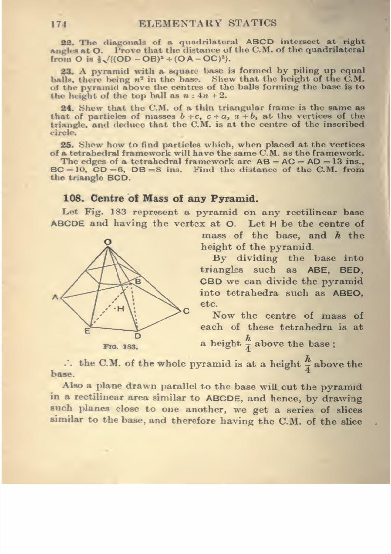
8/4/2019 Elementary Statics of 2 & Dimensions R.J.a. Barnard 1921
http://slidepdf.com/reader/full/elementary-statics-of-2-dimensions-rja-barnard-1921 186/272
174 ELEMENTARY STATICS
22. The diagonals of a quadrilateral ABCD intersect at right
anglM at O. Prove that the distance of the CM. of the quadrilateral
from O is K/{(OD -OB)* +{0A -0C)»).
23.
Apyramid with a square base is formed by piling up equal
balls, there being n^ in the base. Slicw that the height of the CM.of the pyramid above the centres of the balls forming the base is to
the height of the top ball as n : 4n + 2.
84. Shew that the CM. of a thin triangular frame is the same as
that of particles of masses b +c, c+a, a +b, at the vertices of the
triangle, and deduce that the CM. is at the centre of the inscribed
oiiole.
25. Shew how to find particles which, when placed at the vertices
of a tetrahedral framework will have the same CM. as the framework.
The edges of a tetrahedral framework are AS = AC = AD = 13 ins.,
BC = 10, CD =6, DB=8 ins. Find the distance of the CM. from
the triangle BCD.
108. Centre of Mass of any Pyramid.
Let Fig. 183 represent a pyramid on any rectilinear base
ABCDE and having the vertex at O. LetH
be the centre of
mass of the base, and h the
y*. height of the pj^amid.
//^\\ By dividing the base into
/\l\\\ triangles such as ABE, BED,
/ Y ^y c^v ^^^ ^® ^^^ divide the pyramid
. /..---T^^A ; nX. ijito tetrahedra such as ABEO,
\ //'Y ^^ Now the centre of mass of
^ —_A/^^ each of these tetrahedra is at
D. h
Pio 183,a height j above the base
.*. the CM. of the whole pyramid is at a height j above the
base.
Also a plane drawn parallel to the base will cut the pyramid
in a rectilinear area similar to ABCDE, and hence, by drawing
such planes close to one another, we get a series of slices
similar to the base, and therefore having the CM. of the slice
8/4/2019 Elementary Statics of 2 & Dimensions R.J.a. Barnard 1921
http://slidepdf.com/reader/full/elementary-statics-of-2-dimensions-rja-barnard-1921 187/272
CENTRES OF MASS 175
similarly placed to that of the base. Just as in the tetra-
hedron it will follow that the C.M.'s of all the slices are on
the line joining the vertex to the CM. of the base, and con-
sequently that the CM. of the whole tetrahedron is on this
line. And*as the distance of the CM. from the base is a
quarter of the height of the pjTamid, the CM. will be a quarter
of the way along the line AH from H, or three-quarters of the
way along from A.
The above applies to any form of pyramid, including any
cone (which is a pyramid standing on a curvilinear base), and
in particular to the right circular cone.
Hence the CM. of a Right Circular Cone is on its axis, and
three-quarters of the way from the vertex to the base.
109. Truncated Cone or Pyramid.
If the vertex of a cone is cut off by a plane parallel to its
base, the CM. of the remainder can be found by the method of
Art. 105, combined with the result of Art. 108, or may be
worked out independently by integration.
110. Centres of Mass by the Calculus.
Many questions of calculating the position of the centre of
mase of a body of given shape require the use of the Integral
Calculus, and a few of the simpler cases will be worked out
here by it. Some of them may be obtained by algebraic
methods, which are, however, usually more complicated.
In the following work, p will be used for the density of a
body, that is, its mass per unit volume, as grammes per cubic
centimetre, or lbs. per cubic ft. ; <t will be used for the mass
per unit area of a thin plate, as grammes per square centimetre,or lbs. per square ft., of a sheet of metal.
111. Segment oJ a Parabola (or thin parabolic plate) cut
off by an ordinate perpendicular to the axis.
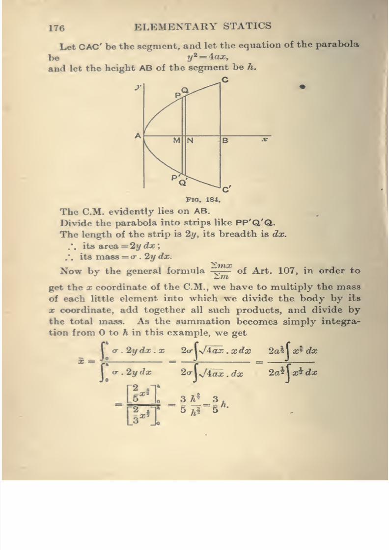
8/4/2019 Elementary Statics of 2 & Dimensions R.J.a. Barnard 1921
http://slidepdf.com/reader/full/elementary-statics-of-2-dimensions-rja-barnard-1921 188/272
176 ELEMENTARY STATICS
Let CAC be the segment, and let the equation of the parabola
bo y^ = iax,
and let the height AB of the segment be h.
C
o^-^.y^
M N B .r
P'^Q ^\
C'
FlO, 184.
The CM. evidently lies on AB.
Divide the parabolainto strips like
PP'Q'Q.The length of the strip is 2?/, its breadth is dx.
.'. its area = 2ydx;
:. its mass = »•. 2 j/ dx.
Now by the general formula ^.— of Art. 107, in order to
get the X coordinate of the CM., we have to multiply the mass
of each little elementinto
which wedivide
the body byits
X coordinate, add together all such products, and divide by
the total mass. As the summation becomes simply integra-
tion from to A in this example, we get
I (r.2ydx.x 2(rWiax.xdx 2a^xidx
\ <T.2ydx 2a\j\^dx 2a^\x^dx
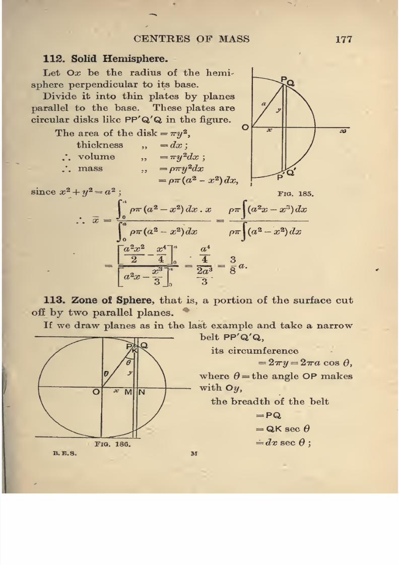
8/4/2019 Elementary Statics of 2 & Dimensions R.J.a. Barnard 1921
http://slidepdf.com/reader/full/elementary-statics-of-2-dimensions-rja-barnard-1921 189/272
CENTRES OF MASS 177
112. Solid Hemisphere.
Let Ox bethe radius of
the hemi-sphere perpendicular to its base.
Divide it into thin plates by planes
parallel to the base. These plates are
circular disks like PP'Q'Q in the figure.
The area of the disk = vy^,
thickness „ ==dx]
.'. volume ,, =iry^(lx;
.'. mass ,,= pTcyMx
= p7r{a^ - x^)dx,
since x^ + y^ = a^
I pir {a^ - x^) dx . X pTr\{a^x- x^)d:
I pTr{a^- x^)dx pTr\{a^-x^)da.
a^x^ x^~
L 2 4 a
r 2 ^nI 2? ~
S""-
113. Zone of Sphere, that is, a portion of the surface cut
off by two parallel planes. "^
If we draw planes as in the last example and take a narrow
belt PP'Q'Q,
its circumference
= 2Try = 27ra cos 0,
where = the angle OP makes
with Oy,
the breadth of the belt
= PQ
= QK sec 6
FiQ. 188. = dx sec 6 ',
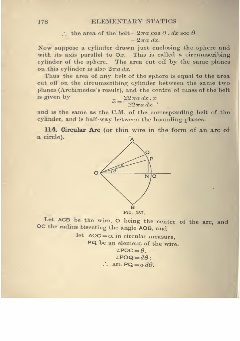
8/4/2019 Elementary Statics of 2 & Dimensions R.J.a. Barnard 1921
http://slidepdf.com/reader/full/elementary-statics-of-2-dimensions-rja-barnard-1921 190/272
178 ELEMENTARY STATICS
.'. the area of the belt = 27ra cos .dx sec 6
= 2iradx.
Now suppose a cylinder drawn just enclosing the sphere and
with its axis parallel to Ox. This is called a circumscribing
cylinder of the sphere. The area cut off by the same planes
on this cylinder is also 27ra dx.
Thus the area of any belt of the sphere is equal to the area
cut off on the circumscribing cylinder between the same two
planes (Archimedes's result), and the centre of mass of the belt
is given by _ _ ^2Tradx.x^~
IS.'Kadx'
and is the same as the CM. of the corresponding belt of the
cylinder, and is half-way between the bounding planes.
114. Circular Arc (or thin wire in the form of an arc of
a circle).^^
BFlO. 187.
Let ACB be the wire, O being the centre of the arc, andOC the radius bisecting the angle AOB, and
let AOC =a in circular measure,
PQ be an element of the wire.
^POC = 0,
i-POQ. = dQ\
.'. arc PQ,=adQ.
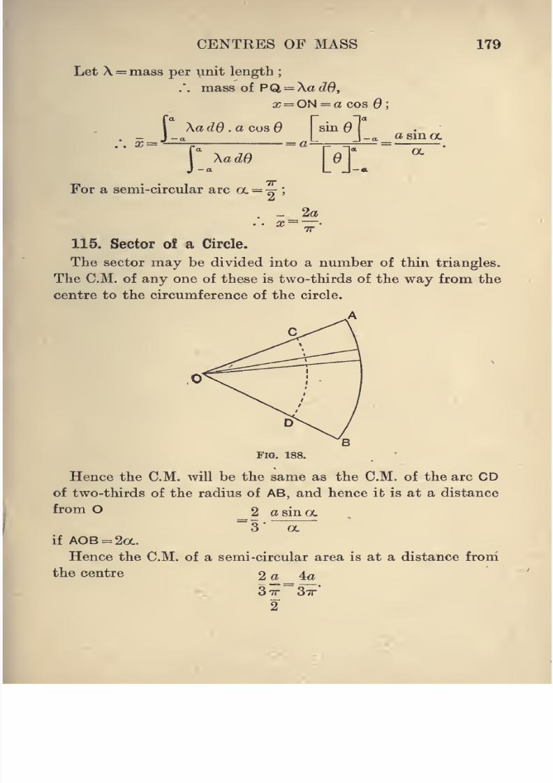
8/4/2019 Elementary Statics of 2 & Dimensions R.J.a. Barnard 1921
http://slidepdf.com/reader/full/elementary-statics-of-2-dimensions-rja-barnard-1921 191/272
CENTRES OF MASS 179
Let X = mass per unit length;
.'. mass of PQ = \adO,
X = ON = a cos ;
I XadO .a COS 6 sin
. -_Jj;:a [ j-a _ asma
For a semi-circular arc a = ^ ;
. - 2aTT
115. Sector of a Circle.
The sector may be divided into a number of thin triangles.
The CM. of any one of these is two-thirds of the way from the
centre to the circumference of the circle.
Fig. 188,
Hence the CM. will be the same as the CM. of the arc CD
of two-thirds of the radius of AB, and hence it is at a distance
from O 2 a sin a~3'
oc
if A0B = 2a.
Hence the CM. of a semi-circular area is at a distance from
the centre 2 a _ 4a
2
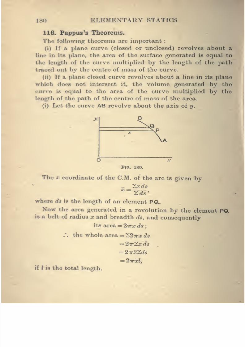
8/4/2019 Elementary Statics of 2 & Dimensions R.J.a. Barnard 1921
http://slidepdf.com/reader/full/elementary-statics-of-2-dimensions-rja-barnard-1921 192/272
180 ELEMENTARY STATICS
116. Pappuses Theorems.
Thft following theorems are important
(i) If a plane curve (closed or unclosed) revolves about a
line in ita plane, the area of the surface generated is equal to
the length of the curve multiplied by the length of the path
traced out by the centre of mass of the curve.
(ii) If a plane closed curve revolves about a line in its plane
which does not intersect it, the volume generated by the
curve is equal to the area of the curve multiplied by the
length of the path of the centre of mass of the area.
(i) Let the curve AB revolve about the axis of y.
FlO. 189.
The X coordinate of the CM. of the arc is given by
where ds is the length of an element PQ.
Now the area generated in a revolution by the element PQis a belt of radius x and breadth (h, and consequently
its area = 2irx ds
.'. the whole area = 22x0: ds
= 27r2x ds
= 2irzlds
= 2xH,
ii lis the total length.
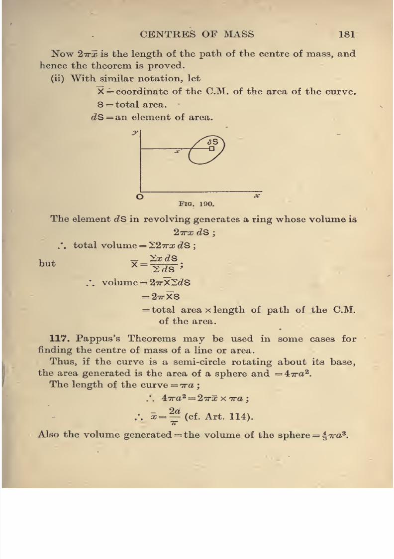
8/4/2019 Elementary Statics of 2 & Dimensions R.J.a. Barnard 1921
http://slidepdf.com/reader/full/elementary-statics-of-2-dimensions-rja-barnard-1921 193/272
8/4/2019 Elementary Statics of 2 & Dimensions R.J.a. Barnard 1921
http://slidepdf.com/reader/full/elementary-statics-of-2-dimensions-rja-barnard-1921 194/272
182 ELEMENTARY STATICS
The area of the semi-circle = Jira-
/. *xo=« = 27rXa7ra2,
X = ||(cf. Art. 115).
ExampUs. 1. In a cubical block of edge 2a a hemispherical
cavity of radius r is hollowed out with its centre at the centre of one
of the faces. Find the CM. of the remainder.
8. In a cubical block of edge 2a a hole is drilled consisting of a
cylinder of radius r terminated by a cone of height h. If the vertexof the cone is at the centre of the block, find the CM. of the remainder.
8. Find the CM. of a truncated right circular cone, the radii of
whose ends are a and b and height h.
Find also the CM. of
(i) the curved surface of the truncated cone,
(ii) the whole surface.
4. A log of wood 12 ft. long is a truncated cone whose ends are
of radii 2 and 3 ft. respectively. Find the volume and CM. of the
whole.
5. With the result of Ex. 2, Art. 107, verify Pappus's theorem
by finding the volume of a truncated cone by revolving the area in
that example about the side b.
6. Shew that the CM. of a homogeneous solid pyramid whosebase is a parallelogram is the same as that of four equal particles
at the angles of the base with a particle of four-thirds of the massof each at the vertex.
7. Find the CM. of a segment of a circle.
8. Find the CM. of a paraboloid of revolution (the solid formedby revolving a parabola about its axis) bounded by a plane perpendi-cular to its axis.
9. Find the CM. of the portion of a sphere bounded by twopftrallel planes.
10. Find the volume and centre of mass of a segment of a sphere.
11. A cylindrical hole of radius r is cut centrally and perpendi-cularly to the base through a hemisphere of radius a. Shew that theCM. of the remainder is at a distance 3v/{o* -r*) from the base.
I
8/4/2019 Elementary Statics of 2 & Dimensions R.J.a. Barnard 1921
http://slidepdf.com/reader/full/elementary-statics-of-2-dimensions-rja-barnard-1921 195/272
CENTRES OF MASS 183
12. Two faces of a solid bounded by planes are rectangles of sides
«!, 61 ; a^, 62, the sides a^, a^ being parallel. • The distance between
these faces is h. Shew that the distance of the CM. from the
rectangle a^, h^ is a,&, + 3ai&i + aA + <^
A ^
13. Shew that if a slice of a spherical shell of any thickness is madeby two parallel planes so as to forma ring, the CM. is midway between
the parallel planes.
14. A uniform thin wire forms a coil of radius a and consists of
m completeturns and - of a turn. Shew that its CM. is at a distancen
.
tt/
"
an sin - {mn + l)7r from the centre.
15. A body is bounded by a rectangle of sides 2a and 2h (b<a)
and four planes through these at equal inclinations 6 to the plane
of the rectangle. Shew that the distance of the CM. from the
rectangle is
h[2a-h)
2{Za-h)tan 9.
16. Find the area of the parabola ?/=^— between the axis of x,
the curve, and the ordinate a;=4a, and find the coordinates of the
CM. of this area.
If this area revolves about the axis of x, find the volume and
CM. of the solid generated.
118. Upsetting of a Body on a Plane.
If a body is placed gently on a horizontal plane and left to
itself, it may remain as placed or it may fall over. Think of it
as held for a moment. It is in contact with the plane at
certain points or over certain areas, and a closed convex polygon
may be draw^n to just enclose all these areas, and this polygon
may be called the base of the body. A convenient way of
thinking of this base as drawn is to suppose a string drawn
as tight as possible and enclosing all the contacts. Thus, if
a table stands on four legs a string passed tightly round the
four feet will enclose the area, which is called the base. The
condition that when left to itself the body will remain standing
is that the vertical through the centre of mass may pass through
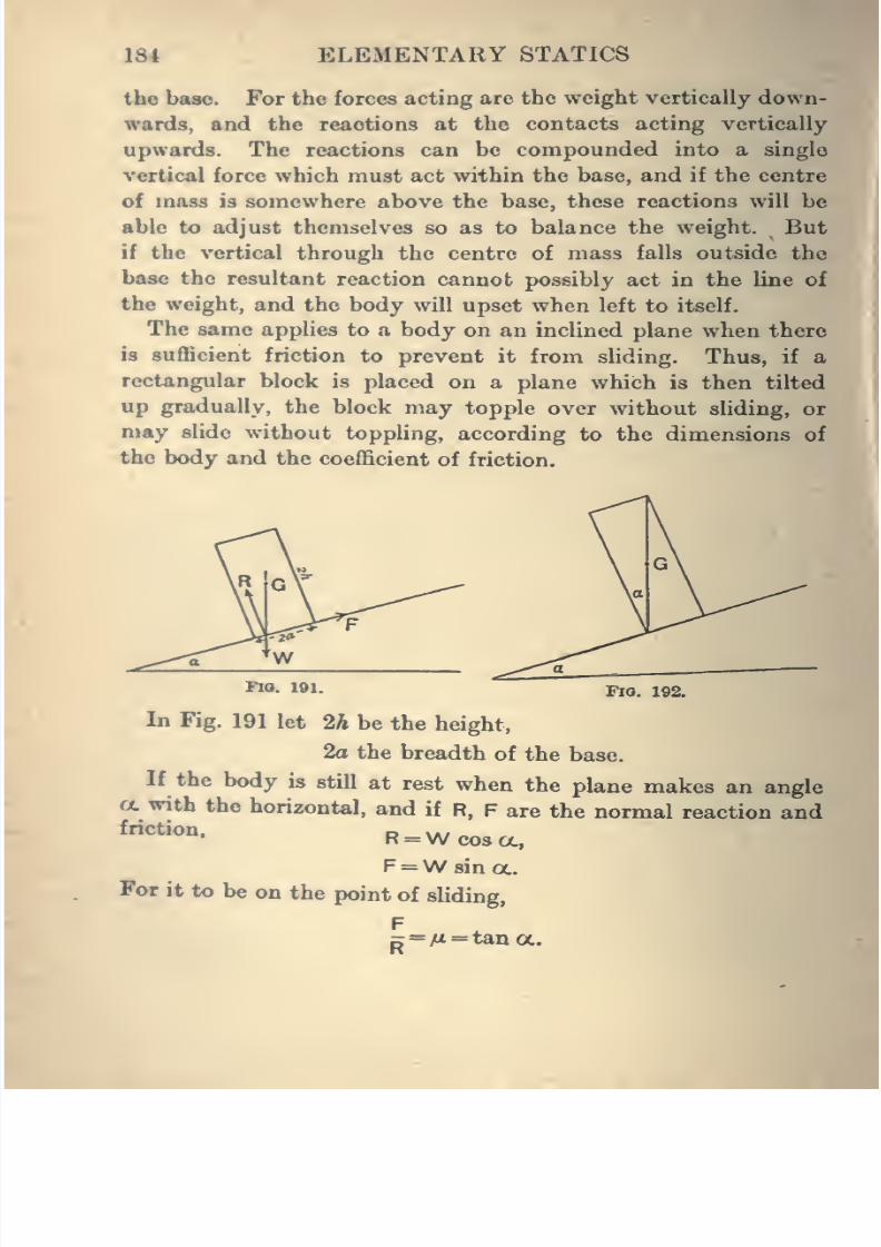
8/4/2019 Elementary Statics of 2 & Dimensions R.J.a. Barnard 1921
http://slidepdf.com/reader/full/elementary-statics-of-2-dimensions-rja-barnard-1921 196/272
134 ELEMENTARY STATICS
the base. For the forces acting are the weight vertically down-
wards, and the reactions at the contacts acting vertically
upwards. The reactions can be compounded into a single
vertical force which must act within the base, and if the centre
of mass is somewhere above the base, these reactions will be
able to adjust themselves so as to balance the weight. But
if the vertical through the centre of mass falls outside the
base the resultant reaction cannot possibly act in the line of
the weight, and the body will upset when left to itself.
The same applies to a body on an inclined plane when there
is sufficient friction to prevent it from sliding. Thus, if a
rectangular block is placed on a plane which is then tilted
up gradually, the block may topple over without sliding, or
may slide without toppling, according to the dimensions of
the body and the coefficient of friction.
^*- i»i- Fia. 192.
In Fig. 191 let 2h be the height,
2a the breadth of the base.
If the body is still at rest when the plane makes an angle
tt with the horizontal, and if R, F are the normal reaction andfriction. d \a/R =W cos a,
F =W sin a.
For it to be on the point of sliding,
F^=Ai = tana.
8/4/2019 Elementary Statics of 2 & Dimensions R.J.a. Barnard 1921
http://slidepdf.com/reader/full/elementary-statics-of-2-dimensions-rja-barnard-1921 197/272
CENTRES OF MASS 185
On the other hand, for it to be on the point of toppling, G
must be vertically above A, as in Fig. 192.
tan oc = v.h
Hence, as the plane is tilted up, the block will slide before
toppling if a
and will topple before sliding if
^<h'
a
EXAMPLES.
1. A circular table of weight W and radius 2a stands on four
vertical legs at a distance a from the centre. What is the least
weight that can upset the table by being placed on it ?
2. A number of equal bricks are piled on top of one another, thelowest being on a horizontal table, and each successive one projecting
over the one below it a distance equal to - of the length of a brick.
How many can be thus placed without their upsetting ?
3. A right circular cone, whose base has a radius of 1 ft. andwhose height is 4 ft., is placed on a plane which is then tilted up.
If the coefficient of friction is greater than unity, shew that the cone
will topplebefore
sliding,
andfind
the inclinationof
the plane whentoppling takes place.
4. A circular cylindrical cup with a flat bottom is made of sheet
metal, of weight lo per unit area. It stands on a horizontal table,
and a rod of weight W is placed in it and projects over the edge.
Shew that the whole wiU upset if the length of the rod is greater than
\/4r^Tp{2 +^ (Trr^ +27rrh)Y
where h is the height of the cylinder and r its radius.
5. A number of strings knotted together at a common point Opass over the smooth edge of a horizontal circular table on which Olies, and carry masses hanging freely at the ends. Shew that if the
system is in equilibrium, either the centre of mass of the masses is
vertically below O or all the strings lie in the same vertical plane.
8/4/2019 Elementary Statics of 2 & Dimensions R.J.a. Barnard 1921
http://slidepdf.com/reader/full/elementary-statics-of-2-dimensions-rja-barnard-1921 198/272
186 ELEMENTARY STATICS
6. A sphere of radius r, whose centre of mass is at a distance a
from the centre, resta on two rough planes each making an angle 45°
with the horizontal. Shew that when slipping is about to take place
the line joining the centre of mass to the centre of the spheremakesan angle 6 with the vertical, where
\^2a sin ^ =r sin 2k,
where k is the angle of friction.
7. A rectangular block of weight W, and of edges 2a, 26, 2c, stands
on a rough horizontal plane. What horizontal force appUed at the
middle of the upper edge will be required to overturn it if the edges
2a are vertical and the force is parallel to the edges 26 ?
Find also the work necessary to be done to upset it.
8. A ladder has its centre of mass one-third of the way up. It
rests against a vertical wall and on a horizontal plane. Shewthat if the coefficient of friction is 1/3 at each end, it is in limiting
equilibrium when the incUnation to the horizontal is tan"' §.
I
8/4/2019 Elementary Statics of 2 & Dimensions R.J.a. Barnard 1921
http://slidepdf.com/reader/full/elementary-statics-of-2-dimensions-rja-barnard-1921 199/272
CHAPTER XL
VIRTUAL WORK.
119. We have already explained the Principle of Virtual
Work as applied to forces acting on a particle. We must
now extend it to the case of any forces acting on a rigid
body.
It is first necessary to examine the displacements possible
for a rigid body capable of moving in one plane. A fuller
treatment will be found in my Elementary Dynamics, Arts.
168-174.
From the meaning of a rigid body any two points of the
body remain at the same distance from one another, however
the body is moved about.
A body is said to be moving in one plane when a plane fixed
in the body moves in a plane fixed in space. Different points
of the body then move in parallel planes. For example, if a
cube slides about on a horizontal table with the same face
always in contact with the table, it is said to be moving in one
plane. In this case all points of the cube move in horizontal
planes.
We will only deal here with motion in a plane.
In any such case all points in a straight line perpendicular
to the planes of motion undergo the same displacement in the
same interval of time, and therefore the displacements of the
whole body may be represented by the displacements of all
points in any one of these planes.
187
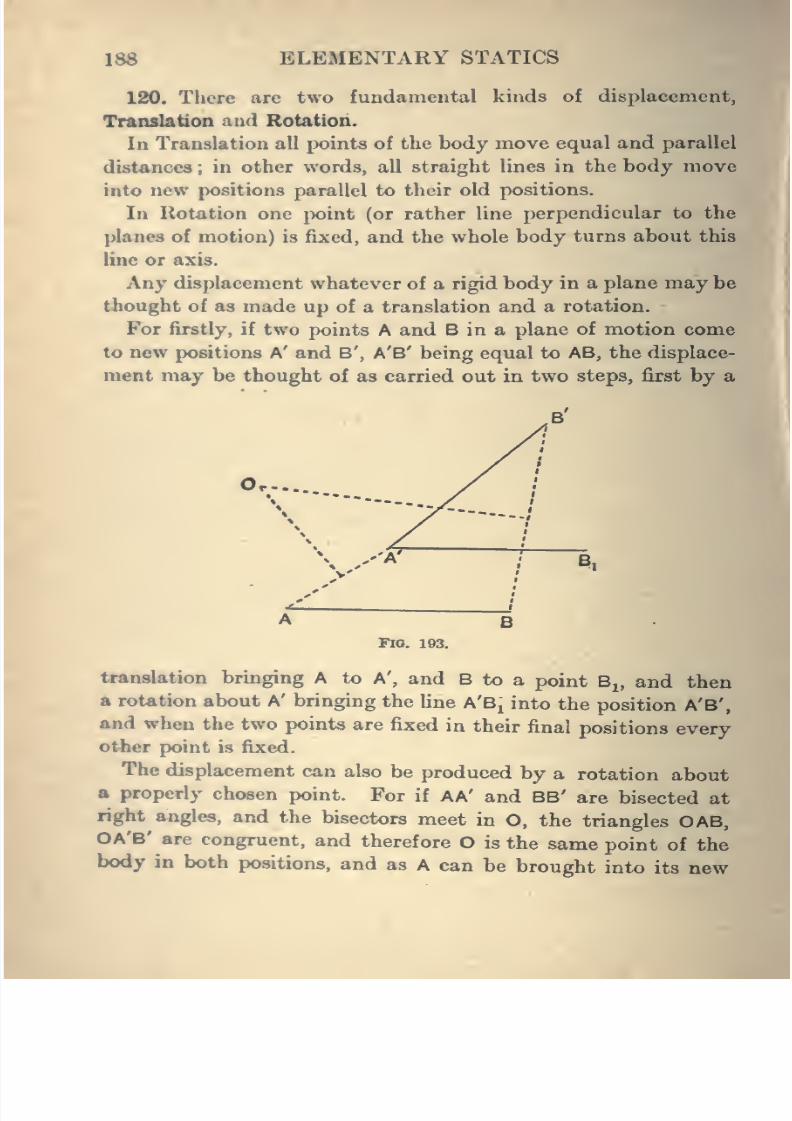
8/4/2019 Elementary Statics of 2 & Dimensions R.J.a. Barnard 1921
http://slidepdf.com/reader/full/elementary-statics-of-2-dimensions-rja-barnard-1921 200/272
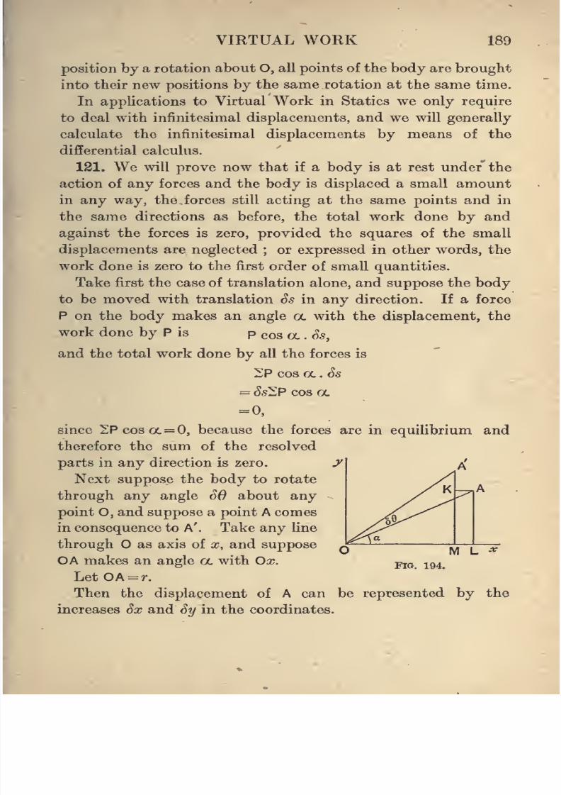
8/4/2019 Elementary Statics of 2 & Dimensions R.J.a. Barnard 1921
http://slidepdf.com/reader/full/elementary-statics-of-2-dimensions-rja-barnard-1921 201/272
VIRTUAL WORK 189
position by a rotation about O, all points of the body are brought
into their new positions by the same rotation at the same time.
In applications to Virtual Work in Statics we only require
to deal with infinitesimal displacements, and we will generally
calculate the infinitesimal displacements by means of the
differential calculus.
121. We will prove now that if a body is at rest under' the
action of any forces and the body is displaced a small amount
in any way, the forces still acting at the same points and in
the same directions as before, the total work done by andagainst the forces is zero, provided the squares of the small
displacements are neglected ; or expressed in other words, the
work done is zero to the first order of small quantities.
Take first the case of translation alone, and suppose the body
to be moved with translation Ss in any direction. If a force
P on the body makes an angle a. with the displacement, the
work done by P is p cos a . Ss,
and the total work done by all the forces is
2P cos a. . Ss
= Ss^P cos oc
= 0,
since 2P cos ol — 0, because the forces are in equilibrium and
therefore the sum of the resolved
parts in any direction is zero.
Next suppose the body to rotate
through any angle SO about any
point O, and suppose a point A comes
in consequence to A'. Take any line
through O as axis of x, and supposeOA makes an angle a. with Ox.
Let OA = r.
Then the displacement of A can be represented by the
increases Sx and Sy in the coordinates.
Fia. 194.
8/4/2019 Elementary Statics of 2 & Dimensions R.J.a. Barnard 1921
http://slidepdf.com/reader/full/elementary-statics-of-2-dimensions-rja-barnard-1921 202/272
190 ELEMENTARY STATICS
Now rfjc»f cos (cL+SS) - r cos a= r (cos a cos Sd - sin a sin SO) - r cos ol ;
also, omitting squares of SO (see Elementary Dynamics^
Art. 113), cos^0 = l,
sin SO = SO,
SO being in circular measure;
.*. Sx= - r sin a. . SO = - y SO.
Again, Sy = r sin (a+ ^0) - r sin a= r (sin a cos SO + cos a. sin SO) - r sin oc
= r(sin a +C0S «, .SO)-r sin a.
= r cos tx . ^0
= xSO.
Now, if P is the force acting at A, and its components are
X and Y, we have proved (Art. 42) that the work done by P
is the sum of the works done by X and Y, also that the work
done by X in the displacement AA' is the sum of the works
done in the displacements Sx and Sy, of which AA' is the
resultant.
.'. the work done = XSx+y Sy
= {Sx-Xy)SO.
Hence the total work done by all the forces is
^{yx-y.y)SQ
= SO^yx-Xy)=0,
since l{yx - Xy) =0 for equilibrium.
122. We could have shortened the above work considerably
if we had used calculus methods, and simply put that, since
a; = r cos a,
Sx =^SoL= -r sin oi. Sol, a - « o (C
where So. has been \ised for the rotation instead of SO.
Similarly, since y = r sin a,
Sy= r COS a.. SO. i: X- 5o^
8/4/2019 Elementary Statics of 2 & Dimensions R.J.a. Barnard 1921
http://slidepdf.com/reader/full/elementary-statics-of-2-dimensions-rja-barnard-1921 203/272
VIRTUAL WORK 191
123. As the total virtual work done in any small displacement
of a rigid body is zero, it is evident that the same is true of any
number of connected bodies. That is to say, if any displace-
ments are given to the bodies with the understanding that the
forces remain constant in magnitude and direction, the virtual
work of the forces is zero, to the first order of small quantities.
The displacements may be any whatever, but in general
it is advisable to take displacements consistent with the
geometrical relations of the bodies. For example, two rods
pressing against one another, or jointed together, will be given
displacements in which they remain in contact. If this is
done it is clear that the reactions between the bodies will not
occur in the equation of virtual work. For the work done by
the force acting on the one rod is equal and opposite to the
work done by the reaction acting on the other. Similarly,
the tension of an inextensible string will not appear, as has been
pointed out in Chapter IV. (Art. 46), but a displacement maybe chosen which produces a change in the length of the string,
and then the virtual work of the tension will appear, and will
be equal to the tension multiplied by the diminution of length.
Such a displacement, it will be noticed, may be made, though
not consistent with the fact that the string is inextensible,
because the displacements are only virtual, that is to say,
" imagined."
124. We will work a few very easy examples, which can also
be easily worked by the methods of the former chapters, but
they will illustrate the method of virtual work, and shew how,
by this method, we can often calculate the force we want to
find without bringing all the other forces into the equations.
The student must be careful about the sign of the workdone in a displacement, remembering that it is positive if the
resolved part of the displacement along the line of action of
the force is in the direction of the force, and if in the opposite
direction negative.
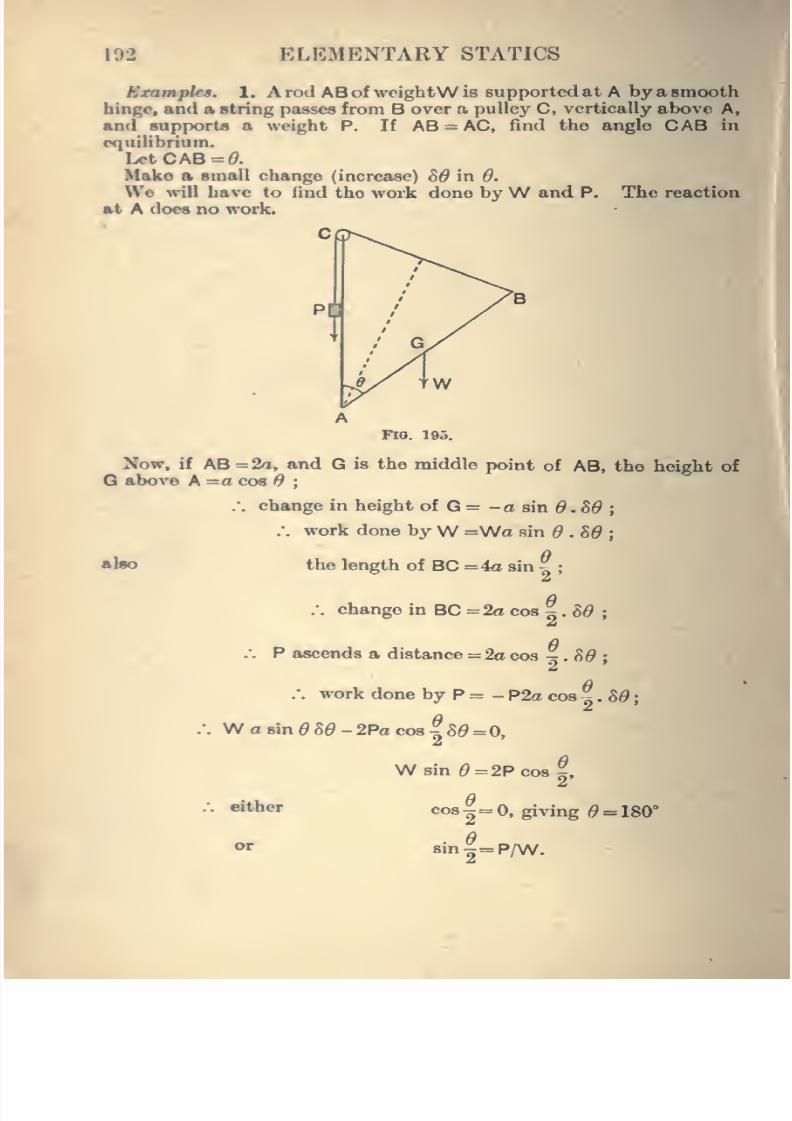
8/4/2019 Elementary Statics of 2 & Dimensions R.J.a. Barnard 1921
http://slidepdf.com/reader/full/elementary-statics-of-2-dimensions-rja-barnard-1921 204/272
192 ELEMENTARY STATICS
Bxamphs. 1. A rod AB ofweightW is supported at A by a smooth
hinge, and a string passes from B over a pulley C, vertically above A,
an<i supports a weight P. If AB = AC, find the angle CAB in
(xpiilibrium.
IjotCAB-O.
Make a small change (increase) 89 in 0.
We will have to find the woi'k done byW and P. The reaction
at A docs no work.
Fio. 195.
Now, if AB=2a, and G is the middle point of AB, the height of
Q above A =a cos $;
/. change in height of G = - o sin ^ . S0;
.-. work done byW =Wa sin 6 .86;
abo the length of BC =4o sin ^ ;
:.
change in BC =2o cos ^ . 8^ ;
/. P ascends a distance = 2acos ^.80 ;
:. work done by P = - P2a cos %.8d',
W a sin ^ S^ - 2Pa cos 1 8^ =0,
either
WBin0 = 2Pcos^,a
co3-= 0, giving 6' = 180°
a
sin^^P/W.
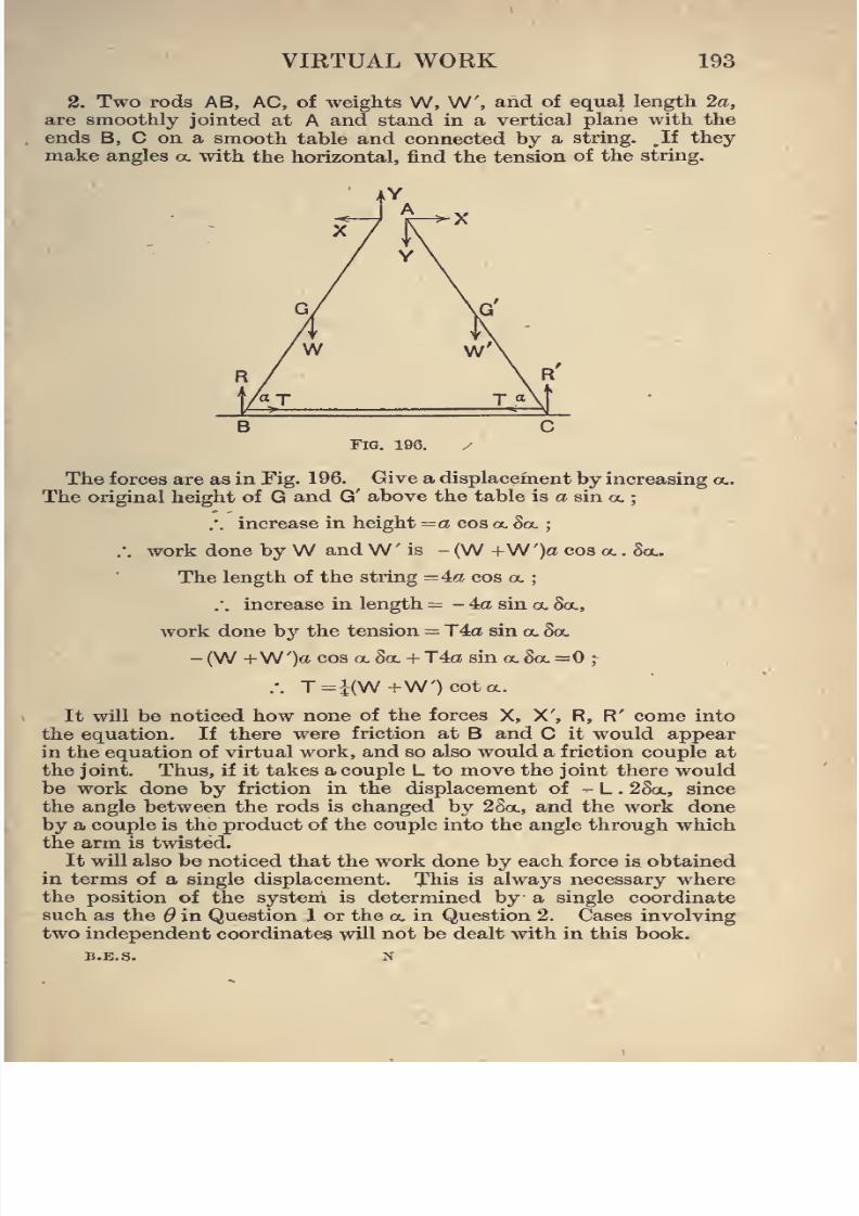
8/4/2019 Elementary Statics of 2 & Dimensions R.J.a. Barnard 1921
http://slidepdf.com/reader/full/elementary-statics-of-2-dimensions-rja-barnard-1921 205/272
VIRTUAL WORK 193
2. Two rods AB, AC, of weights W, W, and of equal length 2a,
are smoothly jointed at A and stand in a vertical plane with the
ends B, C on a smooth table and connected by a string. ,If they
make angles oc with the horizontal, find the tension of the string.
The forces are as in Fig. 196. Give a displacement by increasing oc.
The original height of G and G' above the table is a sin oc ;
.". increase in height —a cos oc 8oc;
.*. work done byW andW is - (W +W')a cos oc . 8oc.
The length of the string = 4a cos oc;
.'. increase in length = - 4a sin oc 8oc,
work done by the tension = T4a sin oc Soc
- (W +W')a cos oc 8oc + T4a sin oc See =0;
.-. T=i(W+W')cota.
It will be noticed how none of the forces X, X', R, R' come into
the equation. If there were friction at B and C it would appear
in the equation of virtual work, and so also would a friction couple at
the joint. Thus, if it takes a couple L to move the joint there would
be work done by friction in the displacement of - L . 28a., since
the angle between the rods is changed by 2Soc, and the work done
by a couple is the product of the couple into the angle through which
the arm is twisted.
It will also be noticed that the work done by each force is obtained
in terms of a single displacement. This is always necessary where
the position of the system is determined by a single coordinate
such as the $ in Question 1 or the oc in Question 2. Cases involving
two independent coordinates will not be dealt with in this book.
B.E.S. N
8/4/2019 Elementary Statics of 2 & Dimensions R.J.a. Barnard 1921
http://slidepdf.com/reader/full/elementary-statics-of-2-dimensions-rja-barnard-1921 206/272
194 ELEMENTARY STATICS
125. The method of virtual work may be applied to just
rigid frames, and can be used to calculate any stress without
bringing the rest into theequation.
Ex. 8. Take the framework worked out in Art. 80, and suppose
w© wanted to find T directly by virtual work. Imagine the bar BC
i«moved. but the forces T to be applied in some way to the joints.
This will still keep the frame in equiUbrium, but it is deformable,
and we can imagine the two halves to rotate each through an angleWabout A and D. This will be found to cause B and C to descend
distanoee a 5^, while the distance BC will be shortened by an amount
2aV35d. Hence the equation of vu^ual work is
- T2aV3 8^ + lOo 5^ + 20o 8^ =0,
T2n^3=30,
T=5s/3.
126. Stable, Unstable, and Neutral Eqailibrinm.
If a thin cylinder, such as a pencil, is placed carefully with
one end on a horizontal plane, it may stand upright ; but if
one tries to stand an equally thin stick, three feet long, upright
on a table, he will probably fail, or at any rate it will not
stand up for more than a fraction of a second. The upright
position is, however, one of equilibrium, but the slightest shake,
an almost infinitesimal puff of air, is sufiBcient to upset it.
If the same stick is supported at the upper end and allowed
to hang down, it
maybe disturbed from that position, but
it returns to it again after the disturbance.
These two cases are called Unstable and Stable equilibrium
respectively. We may define the terms by sajring that if a
body b in equilibrium, and on being displaced slightly from its
position of equilibrium it returns towards that position again,
it is said to be in stable equilibrium ; if, however, it moves
further away from the position of equilibrium, it was in unstable
equilibrium.
In the examples of the pencil and stick above, the body is in
stable equilibrium when the centre of mass is as low as it can
get, and in unstable equilibrium when it is as high as it can get.
>unt
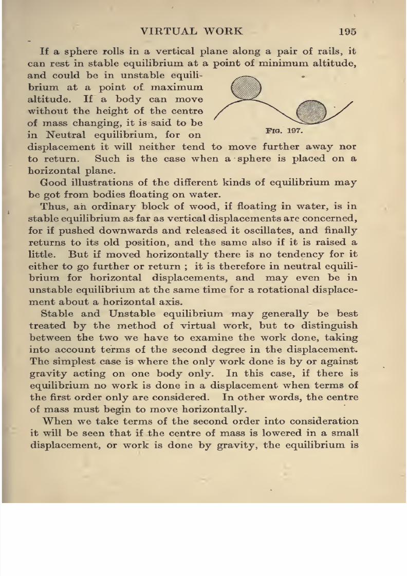
8/4/2019 Elementary Statics of 2 & Dimensions R.J.a. Barnard 1921
http://slidepdf.com/reader/full/elementary-statics-of-2-dimensions-rja-barnard-1921 207/272
VIRTUAL WORK 195
If a sphere rolls in a vertical plane along a pair of rails, it
can rest in stable equilibrium at a point of minimum altitude,
and could be in unstable equili-
brium at a point of maximum
altitude. If a body can move
without the height of the centre
of mass changing, it is said to be
in Neutral equilibrium, for oni
.•
displacement it will neither tend to move further away nor
to return. Such is the case when a sphere is placed on a
horizontal plane.
Good illustrations of the different kinds of equilibrium may
be got from bodies floating on water.
Thus, an ordinary block of wood, if floating in water, is in
stable equilibrium as far as vertical displacements are concerned,
for if pushed downwards and released it oscillates, and finally
returns to its old position, and the same also if it is raised a
Uttle. But if moved horizontally there is no tendency for it
either to go further or return ; it is therefore in neutral equili-
brium for horizontal displacements, and may even be in
unstable equilibrium at the same time for a rotational displace-
ment about a horizontal axis.
Stable and Unstable equilibrium may generally be best
treated by the method of virtual work, but to distinguish
between the two we have to examine the work done, taking
into account terms of the second degree in the displacement.
The simplest case is where the only work done is by or against
gravity acting on one body only. In this case, if there is
equilibrium no work is done in a displacement when terms of
the first order only are considered. In other words, the centre
of mass must begin to move horizontally.
When we take terms of the second order into consideration
it will be seen that if the centre of mass is lowered in a small
displacement, or work is done by gravity, the equilibrium is
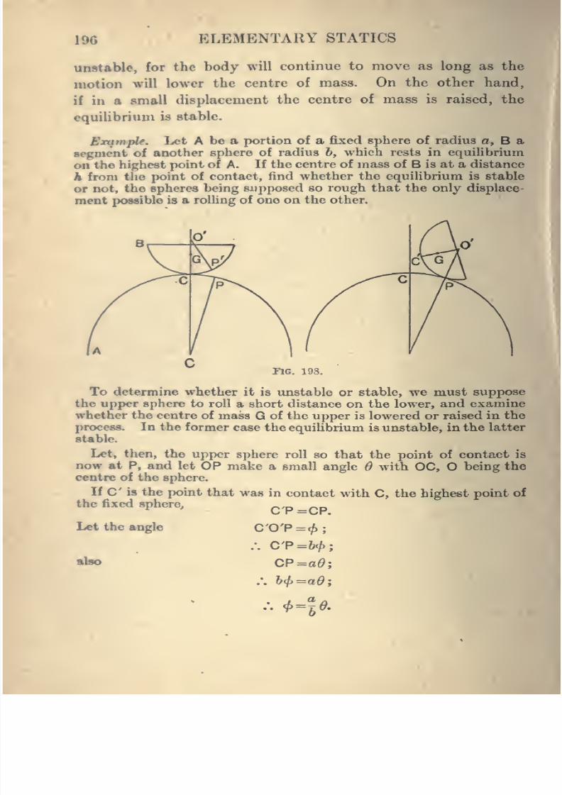
8/4/2019 Elementary Statics of 2 & Dimensions R.J.a. Barnard 1921
http://slidepdf.com/reader/full/elementary-statics-of-2-dimensions-rja-barnard-1921 208/272
196 ELEMENTARY STATICS
unstable, for the body will continue to move as long as the
motion will lower the centre of mass. On the other hand,
if in a small displacement the centre of mass is raised, the
equilibrium b stable.
Example. Let A be a portion of a fixed sphere of radius a, B a
segment of another sphere of radius 6, which rests in equilibrium
on the highest point of A. If the centre of mass of B is at a distance
h from tlio point of contact, find whether the equilibrium is stable
or not, the spheres being supposed so rough that the only displace-
ment possible is a roUing of one on the other.
riG. 198.
To determine whether it is imstable or stable, we must suppose
the upper sphere to roll a short distance on the lower, and examine
whether the centre of mass G of the upper is lowered or raised in the
process. In the former case the equilibrium is unstable, in the latter
stable.
Let, then, the upper sphere roll so that the point of contact is
now at P, and let OP make a small angle $ with OC, O being the
centre of the sphere.
If C is the point that was in contact with C, the highest point of
the fixed sphere.
Let the angle
also
C'P-CP.
:. C'P=b<f>
CP=ad
't'-le.
8/4/2019 Elementary Statics of 2 & Dimensions R.J.a. Barnard 1921
http://slidepdf.com/reader/full/elementary-statics-of-2-dimensions-rja-barnard-1921 209/272
1
, VIRTUAL WORK 197
Consequently O'C has turned through an angle
+<f)
or —r-0.
The new height of Q above Ois
theprojection
onthe vertical of
the broken line OO'G and
= {a +?;)cos 6 -{b -h)cos{6 +4>).
The old height was
a+h or {a+b) -{b -h)
.'. the rise of G
= (a+6)(cos^-l)-(6-/t){cos(6' + c^)-l}
Z [, (J-
^'—pr' -^{ab -ah - bh).
This is positive if
ab -ah -bh>or (a+b)h<ab
, abor h < V
a +b
1 1 1
h a b
In this case equilibrium is stable.
If v < - + T it is unstable.h a b
If r = ^ + V > the equilibrium is neutral to the same degree of
approximation, but on examining terms of higher degrees it will be
found that it is not really neutral, but unstable.
EXAMPLES.
1. Four uniform bars, each of weight w and length a, are smoothly
jointed together to form a rhombus ABCD. AB is fixed horizontally,
and a light string joins A to C. Find the tension in the string if the
angle DAB is a.
8/4/2019 Elementary Statics of 2 & Dimensions R.J.a. Barnard 1921
http://slidepdf.com/reader/full/elementary-statics-of-2-dimensions-rja-barnard-1921 210/272
198 ELEMENTARY STATICS
2. A Binoothly jointed rhombus ABCD, of side a, is formed of
uniform rods, and is supported at the point A and kept from col-
lafwing by a Hght elastic string AC of natural length d and modulus A.
Show that the length of string in the position of equilibrium is
dA +^) , whereW is the total weight.
8. A heavy rod rests with one end on a smooth horizontal table
and the other against a smooth vertical wall. The lower end of the
rod is connect^ with a point in the wall by a horizontal elastic
string of natural length — of the length of the rod, and modulus
equal to the weight of the rod. Shew that there is equilibrium when
the rod makes an angle of 45° with the vertical.
4. AB, BC, CD are three equal heavy rods smoothly jointed at
B and C. A, C, and B, D, are joined by light strings of lengths v 3
times that of a rod, and the frame rests in a vertical plane with
AD on a smooth horizontal floor. Find the tensions of the strings.
6. A smoothly jointed parallelogram of uniform bars ABCDhas the mid points of AD, BC smoothly jointed at two fixed points
in the same vertical so as to form a Roberval's Balance. To the
middle of the top bar AD is fixed at right angles a pointer of length I
and weight lo per unit length. Shew that when weights V^,W are
attached at A and D respectively, the inclination 6 of the pointer
to the vertical is given by
where AD =a.
8. A rod AB of weight W is hinged at A and supported by a
string attached at B and passing over a pulley at C vertically aboveA, and then along an arc CE of a smooth vertical circle of which Ais the centre. A weightW is attached to the end of the string andcan sUde along the arc. If AC = AB, and the whole length of the
string is equal to the quadrant of the circle, prove that there will
be equilibrium when AD makes an angle 6 with the horizontal, where
^=2 cos 6^,
6 being in circular measure.
Vaify with your tables that ^=59° 1' nearly.
7. ABCD is a jointed rhombus of equal rods. AB is fixed
horizontally, and a string of natural length SAB and modulus equalto the weight of one bar connects AC. Shew that BC makes anangle 26 with the horizontal given by
6 cos 2^ -2 sin 2d + 3sih 6=0.
8/4/2019 Elementary Statics of 2 & Dimensions R.J.a. Barnard 1921
http://slidepdf.com/reader/full/elementary-statics-of-2-dimensions-rja-barnard-1921 211/272
VIRTUAL WORK 199
8. A square formed of four uniform heavy rods, smoothly jointed
at the corners, is suspended from one of the corners and kept square
by a weightless rod along the horizontal diagonal. Shew that the
thrust in this rod is half the weight of the square.
9. A weightless, smoothly jointed rhombus has its oppositecorners joined by stretched strings. Shew that the tensions of the
strings must be in the ratio of their lengths.
10. ABCD is a jointed rhombus of weightless rods with another
weightless rod joining BD. Equal forces F are apphed at A and Calong AC. Find the stress in BD.
11. A rectangular block of wood, whose vertical dimension is a,
rests on top of a fixed sphere of radius b. Is the equilibrium stable
or unstable ?
12. A hemisphere of radius a rests on top of a fixed sphere of
radius b. Find whether the equihbrium is stable or unstable
(i) When the curved surfaces are in contact,
(ii) When the plane surface of the hemisphere is in contact with
the sphere.
13. A half cylinder of radius a rests on top of a fixed sphere of
radius b. Find if the equilibrium is stable or unstable when the
curvedsurfaces are in contact
(i) For displacements at right angles to the length of the
cylinder.
(ii) For displacements in the direction of the length.
Find also if it is stable or unstable when the flat surface is down-
wards.
14. A heavy rod rests horizontally on two smooth planes, each at
an angle 45^ with the horisiontal. Is the equilibrium stable or
unstable ?
15. Two equal rods, each of length 4a, are jointed together at one
end and rest in equilibrium, touching a horizontal cyhnder of radius
a. Prove that in equilibrium the rods make an angle 45° with the
vertical. Is the equilibrium stable or unstable ?
8/4/2019 Elementary Statics of 2 & Dimensions R.J.a. Barnard 1921
http://slidepdf.com/reader/full/elementary-statics-of-2-dimensions-rja-barnard-1921 212/272
CHAPTER XII
GRAPHICAL STATICS
127. We have used graphical methods for solving examples
first in Art. 24, where the forces acted at a point, and secondly
in Chap. VII., in obtaining the stresses in a weightless frame-
work. But in the latter case it was because the question was
reduced to one of dealing with the forces acting on each
pin separately, or in other words to a series of cases of
forces acting at a point, that we were able to find the forces
graphically.
We now come to deal with the more difficult case when any
forces in a plane act on a body. We will first shew how to
obtain in magnitude, direction and position, the resultant of
any number of forces acting in any position in a plane, and the
graphical conditions for equilibrium will naturally follow.
It will be best to take first the case of three forces not
meeting in a point, and when this is grasped the method can
be applied at once to any number of forces.
128. Let then P, Q, R, be three forces given completely in
magnitude, direction and line of action.
We have seen that the resultant is the same in magnitude
and direction as if the three forces met in a point, and can
therefore be determined at once by drawing a force diagram
(Fig. 200) ABCD, with its sides representing the forces in
magnitude and direction ; then AD represents the resultant
200
^
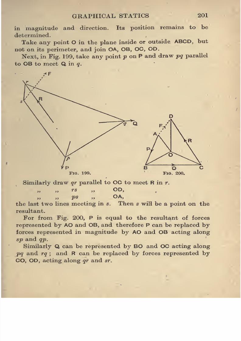
8/4/2019 Elementary Statics of 2 & Dimensions R.J.a. Barnard 1921
http://slidepdf.com/reader/full/elementary-statics-of-2-dimensions-rja-barnard-1921 213/272
GRAPHICAL STATICS 201
in magnitude and direction. Its position remains to be
determined.
Take any point O in the plane inside or outside ABCD, but
not on its perimeter, and join OA, OB, OC, OD.
Next, in Fig. 199, take any point y on P and draw pq parallel
to OB to meet Q,m q.
Fig. 199.
Similarly draw qr parallel to 00 to meet R in r.
rs „ OD,
ps „ OA,
the last two lines meeting in s. Then s will be a point on the
resultant.
For from Fig. 200, P is equal to the resultant of forces
represented by AO and OB, and therefore P can be replaced by
forces representedin
magnitude by AO and OB acting alongsp and qp.
Similarly Q can be represented by BO and OC acting along
pq and rq ; and R can be replaced by forces represented by
CO, OD, acting along qr and sr.
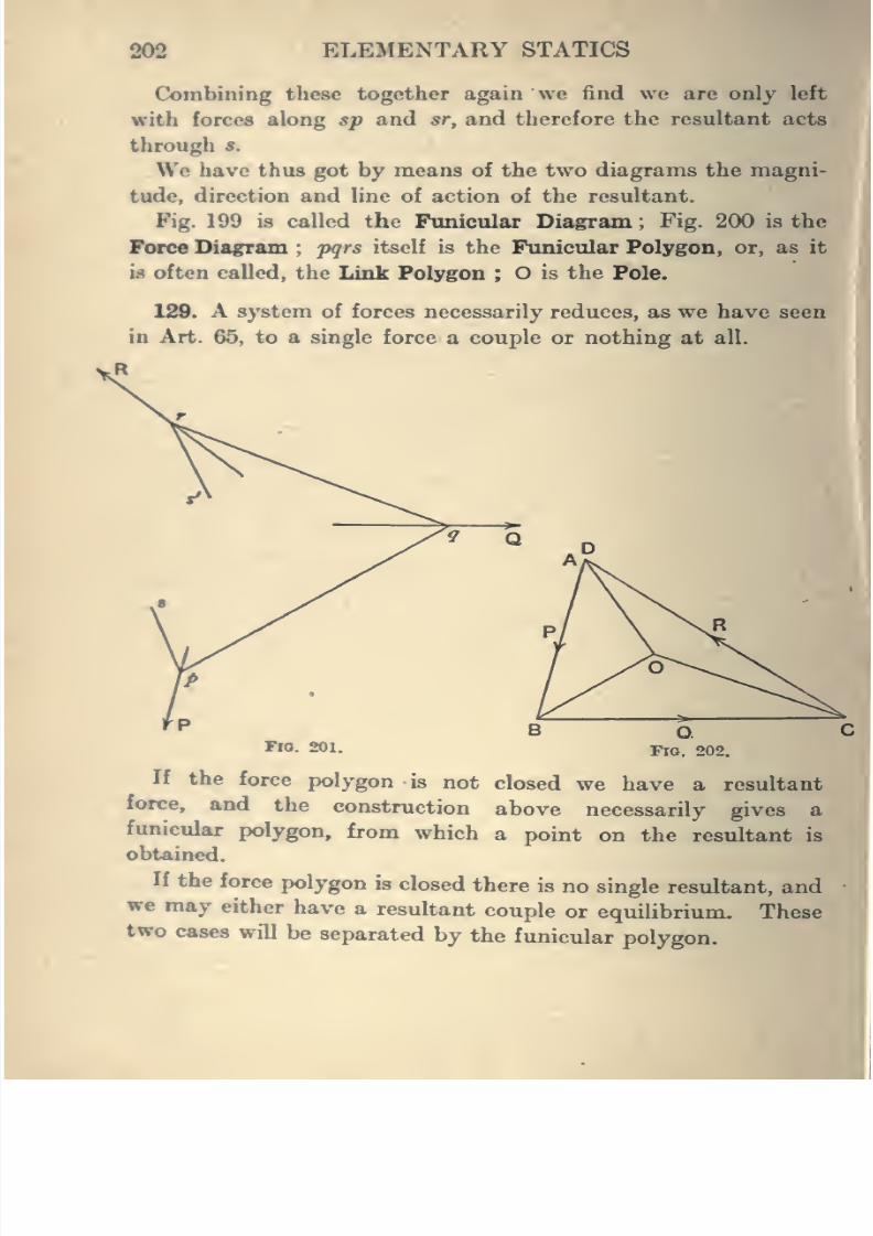
8/4/2019 Elementary Statics of 2 & Dimensions R.J.a. Barnard 1921
http://slidepdf.com/reader/full/elementary-statics-of-2-dimensions-rja-barnard-1921 214/272
202 ELEMENTARY STATICS
Combining these together again we find we arc only left
with forces along sp and sr, and therefore the resultant acts
through 8.
We have thus got by means of the two diagrams the magni-
tude, direction and line of action of the resultant.
Fig. 199 is called the Funicular Diagram; Fig. 200 is the
Force Diagram;pqrs itself is the Funicular Polygon, or, as it
is often called, the Link Polygon ; O is the Pole.
120. A system of forces necessarily reduces, as we have seen
in Art. 65, to a single force a couple or nothing at all.
FlO. 201.
U the force polygon is not closed we have a resultant
force, and the construction above necessarily gives a
funicular polygon, from which a point on the resultant is
obtained.
If the force polygon is closed there is no single resultant, andwe may either have a resultant couple or equilibrium. These
two cases will be separated by the funicular polygon.
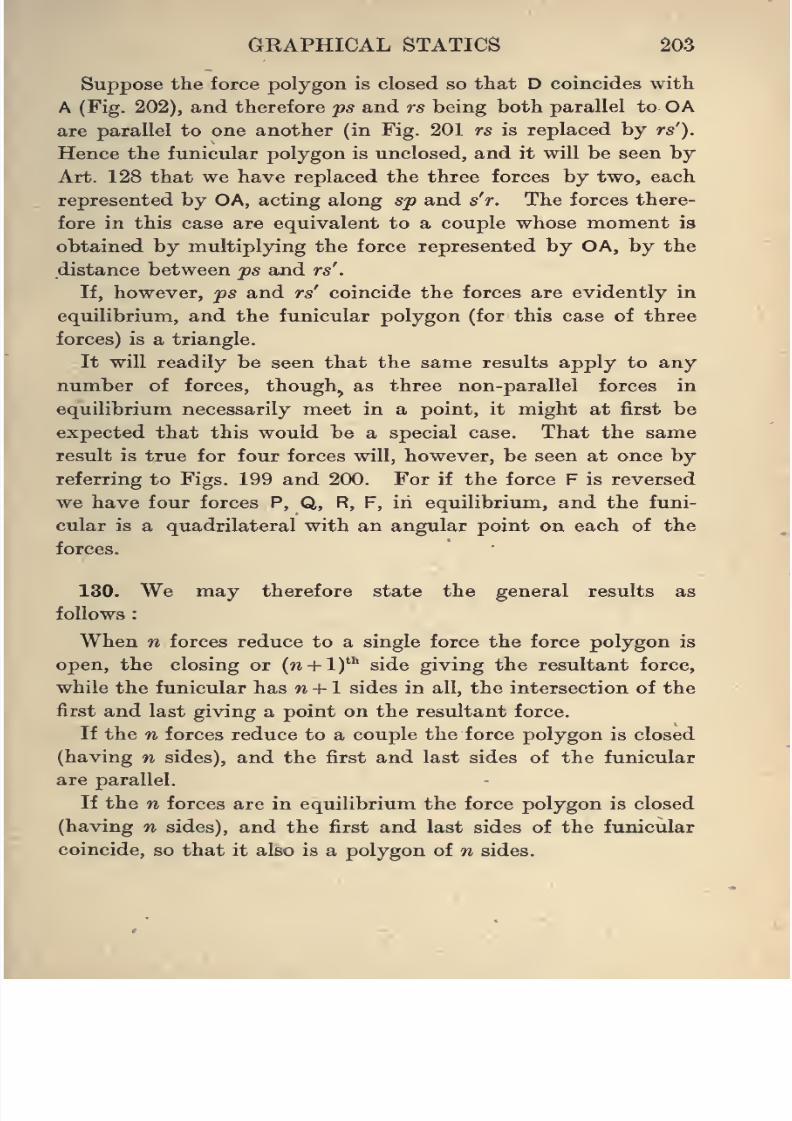
8/4/2019 Elementary Statics of 2 & Dimensions R.J.a. Barnard 1921
http://slidepdf.com/reader/full/elementary-statics-of-2-dimensions-rja-barnard-1921 215/272
GRAPHICAL STATICS 203
Suppose the force polygon is closed so that D coincides with
A (Fig. 202), and therefore ps and rs being both parallel to OA
are parallel to one another (in Fig. 201 rs is replaced by rs').
Hence the funicular polygon is unclosed, and it will be seen by
Art. 128 that we have replaced the three forces by two, each
represented by OA, acting along sp and s'r. The forces there-
fore in this case are equivalent to a couple whose moment is
obtained by multiplying the force represented by OA, by the
distance between ps and rs'
.
If, however, jps and rs' coincide the forces are evidently in
equilibrium, and the funicular polygon (for this case of three
forces) is a triangle.
It will readily be seen that the same results apply to any
number of forces, though^ as three non-parallel forces in
equilibrium necessarily meet in a point, it might at first be
expected that this would be a special case. That the same
result is true for four forces will, however, be seen at once byreferring to Figs. 199 and 200. For if the force F is reversed
we have four forces P, Q, R, F, in equilibrium, and the funi-
cular is a quadrilateral with an angular point on each of the
forces.
130. We may therefore state the general results as
follows
When n forces reduce to a single force the force polygon is
open, the closing or (w + 1)"' side giving the resultant force,
while the funicular has w -1- 1 sides in all, the intersection of the
first and last giving a point on the resultant force.
If the n forces reduce to a couple the force polygon is closed
(having n sides), and the first and last sides of the funicular
are parallel.
If the n forces are in equilibrium the force polygon is closed
(having n sides), and the first and last sides of the funicular
coincide, so that it also is a polygon of n sides.
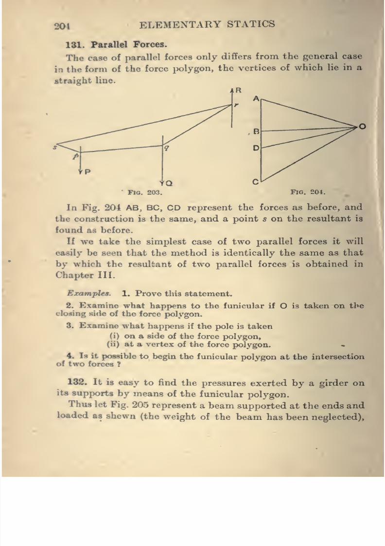
8/4/2019 Elementary Statics of 2 & Dimensions R.J.a. Barnard 1921
http://slidepdf.com/reader/full/elementary-statics-of-2-dimensions-rja-barnard-1921 216/272
20t ELEMENTARY STATICS
131. Parallel Forces.
The case of parallel forces only differs from the general case
in the form of the force polygon, the vertices of which lie in a
straight line.
Fia. 203. Fio. 204.
In Fig. 204 AB, BC, CD represent the forces as before, and
the con.struction is the same, and a point s on the resultant is
found as before.
If we take the simplest case of two parallel forces it will
easily be seen that the method is identically the same as that
by which the resultant of two parallel forces is obtained in
Chapter III.
Examples. 1. Prove this statement.
2. Examine what happens to the funicular if O is taken on the
closing side of the force polygon.
3. Examine what happens if the pole is taken
(i) on a side of the force polygon,
(ii) at a vertex of the force polygon. •.
4. Is it possible to begin the funicular polygon at the intersection
of two forces ?
132. It is easy to find the pressures exerted by a girder on
its supports by means of the funicular polygon.
Thus let Fig. 205 represent a beam supported at the ends and
loaded as shewn (the weight of the beam has been neglected).
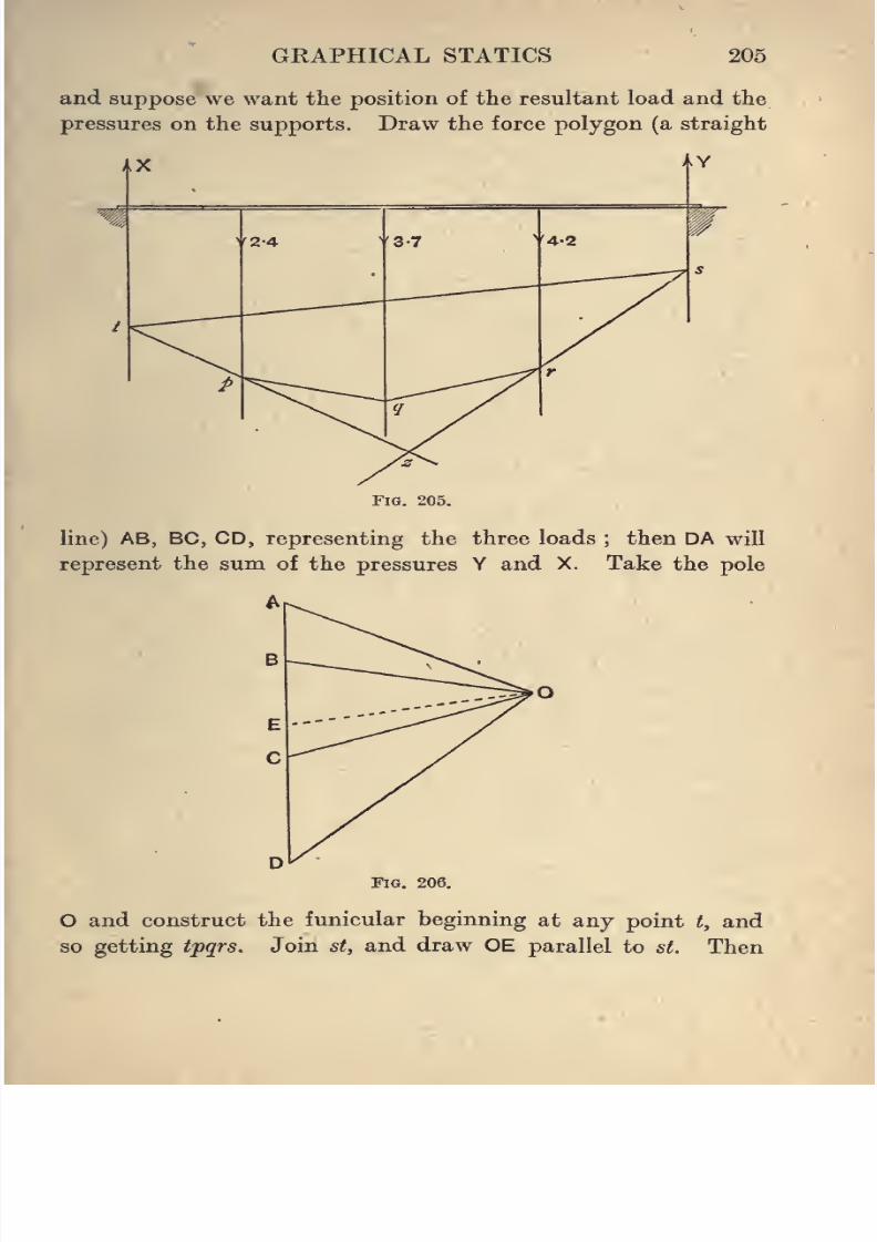
8/4/2019 Elementary Statics of 2 & Dimensions R.J.a. Barnard 1921
http://slidepdf.com/reader/full/elementary-statics-of-2-dimensions-rja-barnard-1921 217/272
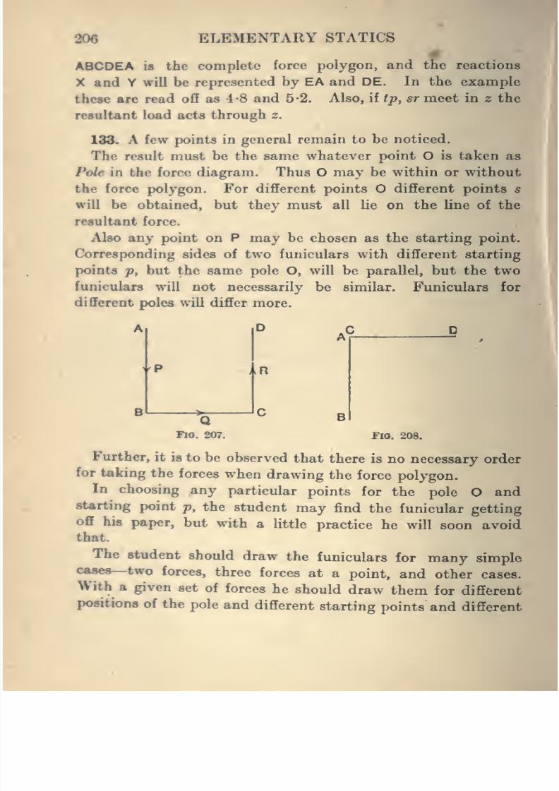
8/4/2019 Elementary Statics of 2 & Dimensions R.J.a. Barnard 1921
http://slidepdf.com/reader/full/elementary-statics-of-2-dimensions-rja-barnard-1921 218/272
206 ELEMENTARY STATICS
ABCDEA is the complete force polygon, and the reactions
X and Y will be represented by EA and DE. In the example
these are read off as 4-8 and 5 •2. Also, if tjp, sr meet in z the
resultant load acts through z.
133. A few points in general remain to be noticed.
The result must be the same whatever point O is taken as
Pole in the force diagram. Thus O may be within or without
the force polygon. For different points O different points s
will be obtained, but they must all lie on the line of the
resultant force.
Also any point on P may be chosen as the starting point.
Corresponding sides of two funiculars with different starting
points p, but the same pole O, will be parallel, but the two
funiculars will not necessarily be similar. Funiculars for
different poles will differ more.
"P uR
Q
Fio. 207. Fig. 208.
Further, it is to be observed that there is no necessary order
for taking the forces when drawing the force polygon.
In choosing any particular points for the pole O and
starting point p, the student may find the funicular getting
off his paper, but with a little practice he will soon avoid
that.
The student should draw the funiculars for many simple
cases—two forces, three forces at a point, and other cases.
With a given set of forces he should draw them for different
positions of the pole and different starting points and different
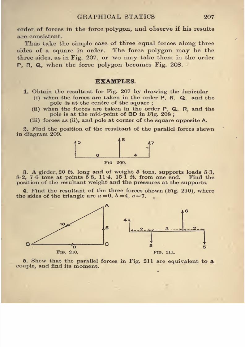
8/4/2019 Elementary Statics of 2 & Dimensions R.J.a. Barnard 1921
http://slidepdf.com/reader/full/elementary-statics-of-2-dimensions-rja-barnard-1921 219/272
GRAPHICAL STATICS 207
order of forces in the force polygon, and observe if Bis results
are consistent.
Thus take the simple case of three equal forces along three
sides of a square in order. The force polygon may be the
three sides, as in Fig. 207, or we may take them in the order
P, R, Q, when the force polygon becomes Fig. 208.
EXAMPLES.
1. Obtain the resultant for Fig. 207 by drawing the funicular
(i) when the forces are taken in the order P, R, Q, and the
pole is at the centre of the square;
(ii) when the forces are taken in the order P, Q, R, and the
pole is at the mid-point of BD in Fig. 208;
(iii) forces as (ii), and pole at corner of the square opposite A.
2. Find the position of the resultant of the parallel forces shewnin diagram 209.
15 r 17
Fio 209.
3. A girder, 20 ft. long and of weight 5 tons, supports loads 5-3,
8-2, 7-6 tons at points 6-8, 11-4, 151 ft. from one end. Find the
position of the resultant weight and the pressures at the supports.
4. Find the resultant of the three forces shewn (Fig. 210), wherethe sides of the triangle are a -6, 6 =4, c = 7.
A6
4i
.2_. .3.— = ..2_-
FIG. 211.
5. Shew that the parallel forces in Fig. 211 are equivalent to acouple, and find its moment.
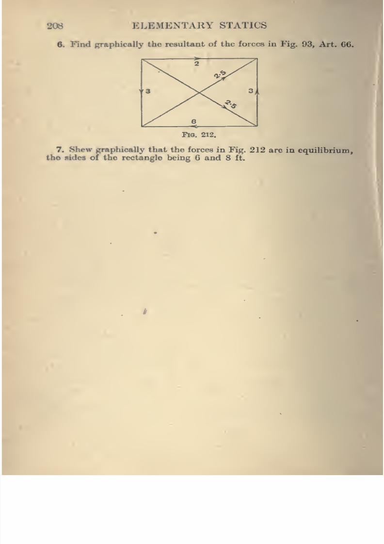
8/4/2019 Elementary Statics of 2 & Dimensions R.J.a. Barnard 1921
http://slidepdf.com/reader/full/elementary-statics-of-2-dimensions-rja-barnard-1921 220/272
208 ELEMENTARY STATICS
6. Find graphically the resultant of the forces in Fig. 93, Art. 66.
Fia. 212.
7. Shew graphically that the forces in Fig. 212 are in equilibrium, ^
the sides of the rectangle being 6 and 8 ft. \i\
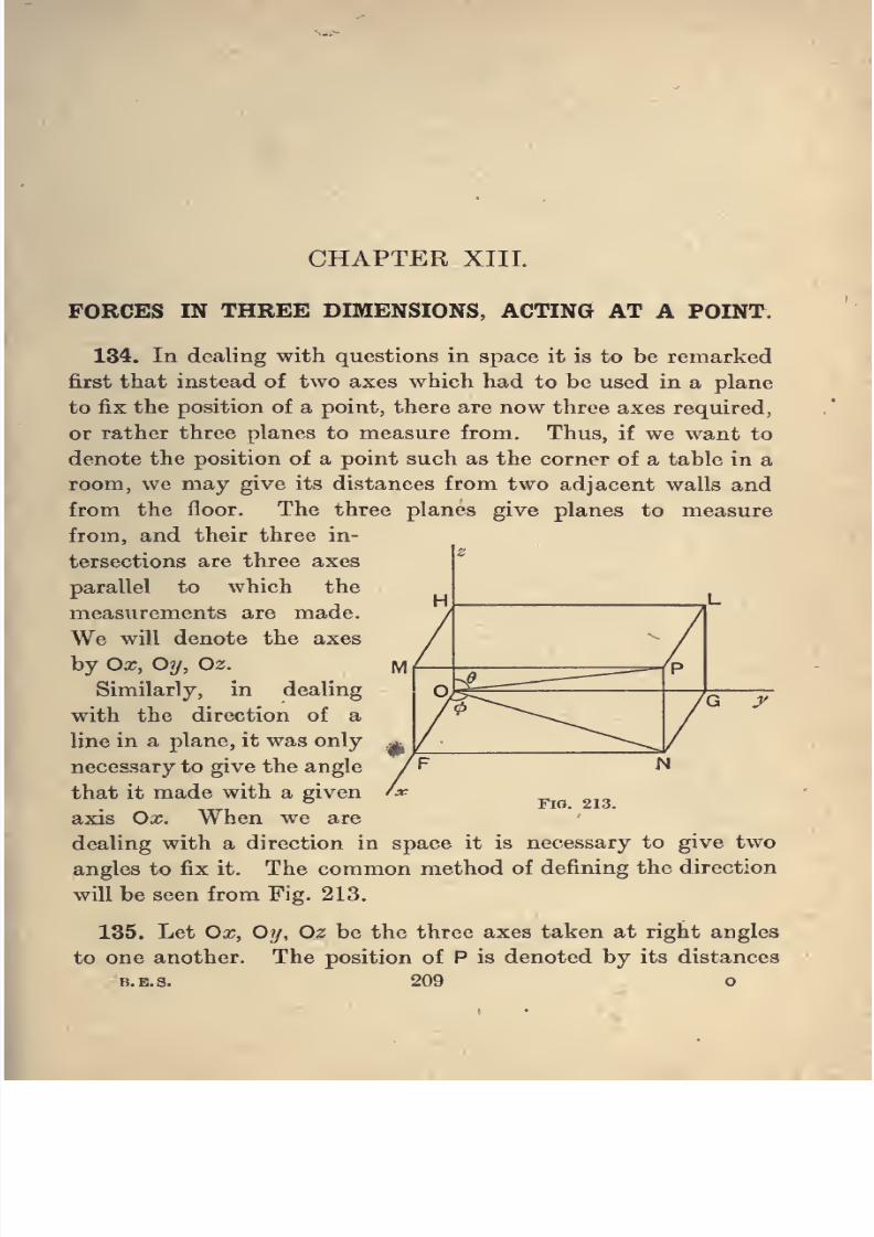
8/4/2019 Elementary Statics of 2 & Dimensions R.J.a. Barnard 1921
http://slidepdf.com/reader/full/elementary-statics-of-2-dimensions-rja-barnard-1921 221/272
CHAPTER XIII.
FORCES IN THREE DIMENSIONS, ACTING AT A POINT.
134. In dealing with questions in space it is to be remarked
first that instead of two axes which had to be used in a plane
to fix the position of a point, there are now three axes required,
or rather three planes to measure from. Thus, if we want to
denote the position of a point such as the corner of a table in a
room, we may give its distances from two adjacent walls and
from the floor. The three planes give planes to measure
from, and their three in-
tersections are three axes
parallel to which the
measurements are made.
We will denote the axes
by Ox, Oy, Oz.
Similarly, in dealing
with the direction of a
line in a plane, it was only
necessary to give the angle
that it made with a given
axis Ox. When we are
dealing with a direction in spaceit is
necessary togive
twoangles to fix it. The common method of defining the direction
will be seen from Fig. 213.
135. Let Ox, Oy, Oz be the three axes taken at right angles
to one another. The position of P is denoted by its distances
B.E.S. 209 o
FlO. 213.
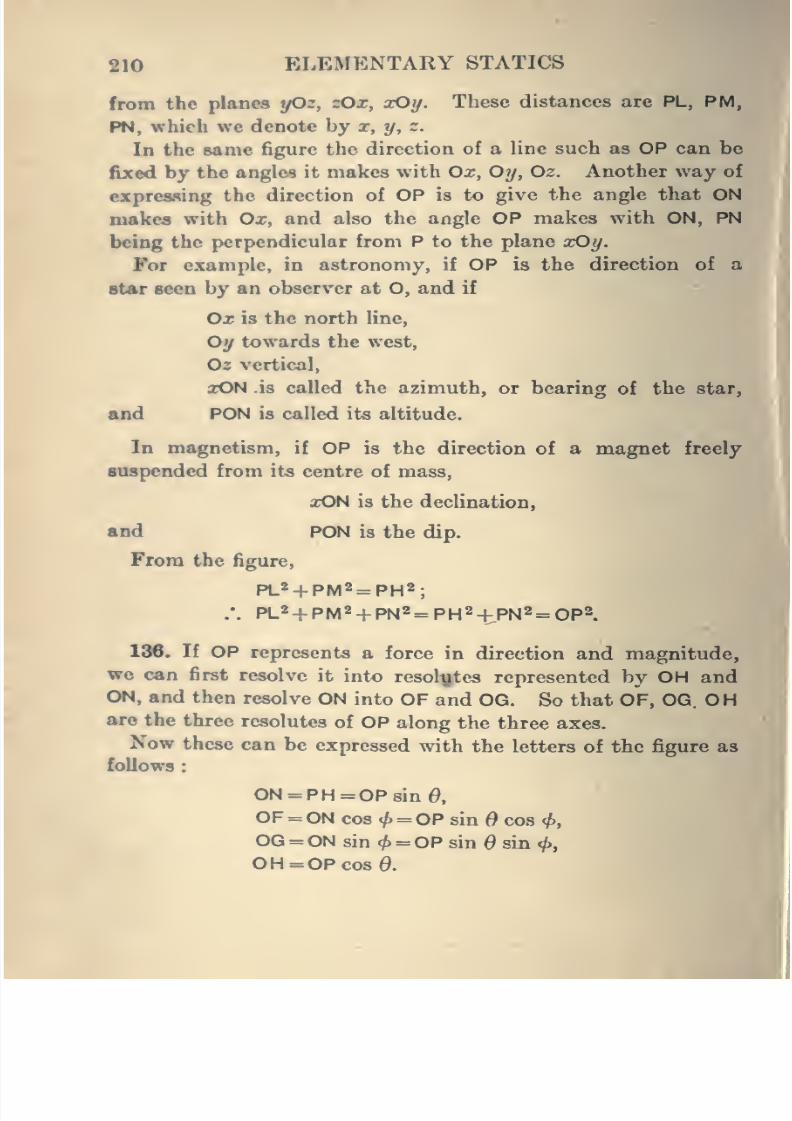
8/4/2019 Elementary Statics of 2 & Dimensions R.J.a. Barnard 1921
http://slidepdf.com/reader/full/elementary-statics-of-2-dimensions-rja-barnard-1921 222/272
210 ELEMENTARY STATICS
from the planes yOz, zOx, xOy. These distances are PL, PM,
PN, which we denote by x, y, z.
In the same figure the direction of a line such as OP can be
fixed by the angles it makes with Ox, Oy, Oz. Another way of
expresfting the direction of OP is to give the angle that ON
makes with Ox, and also the angle OP makes with ON, PN
being the perpendicular from P to the plane xOy.
For example, in astronomy, if OP is the direction of a
star seen by an observer at O, and if
Ox is the north line,
Oy towards the west,
02 vertical,
aON is called the azimuth, or bearing of the star,
And PON is called its altitude.
In magnetism, if OP is the direction of a magnet freely
suspended from its centre of mass,
xON is the declination,
and PON is the dip.
From the figure,
PL«+ PM« = PH2;
.-. PL«+PM2+PN2= PH2-|-PN2 = Opa.
186. If OP represents a force in direction and magnitude,
we can first resolve it into resolytes represented by OH and
ON, and then resolve ON into OF and OG. So that OF, OG. OHare the three resolutes of OP along the three axes.
Now these can be expressed with the letters of the figure as
follows
ON = PH=OPsin0,
OF = ON cos </) = OP sin cos<f),
OG = ON sin <^ = 0P sin 6 sin <p,
OH = OP cos 0.
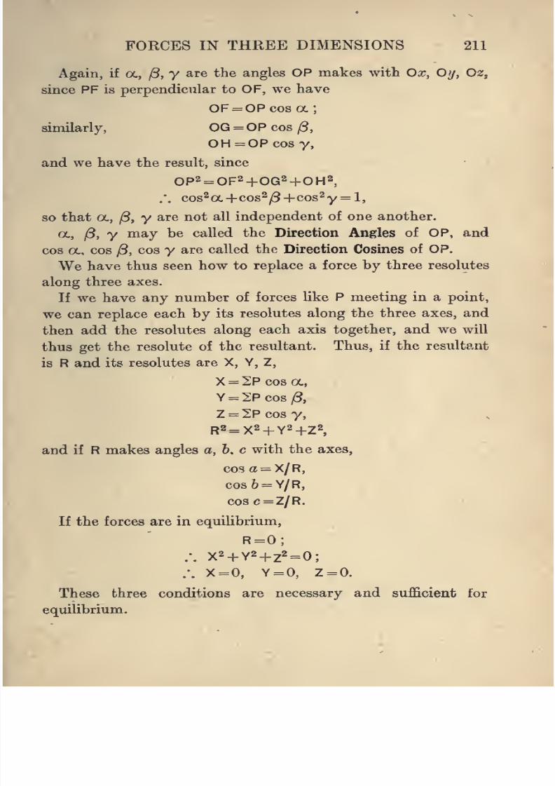
8/4/2019 Elementary Statics of 2 & Dimensions R.J.a. Barnard 1921
http://slidepdf.com/reader/full/elementary-statics-of-2-dimensions-rja-barnard-1921 223/272
FORCES IN THREE DIMENSIONS 211
Again, if oc, /3, y are the angles OP makes with Ox, Oij, Oz,
since PF is perpendicular to OF, we have
OF= OPcosoc;
similarly, OG = OP cos ^,
OH=OPcos y,
and we have the result, since
OP2= OF2+OG2+OH2,
.'. cos^a.+cos2/3+cos2y= l,
so that oc, /3, y are not all independent of one another.
oc, |5, y may be called the Direction Angles of OP, and
cos a, cos ^, cos y are called the Direction Cosines of OP.
We have thus seen how to replace a force by three resolutes
along three axes.
If we have any number of forces like P meeting in a point,
we can replace each by its resolutes along the three axes, and
then add the resolutes along each axis together, and we will
thus get the resolute of the resultant. Thus, if the resultant
is R and its resolutes are X, Y, Z,
X = 2P cos a,
Y = 2Pcos;8,
Z = 2Pcosy,
R2=X2 + Y2+Z2,
and if R makes angles a, 6, c with the axes,
cosa = X/R,
cosfe = Y/R,
cosc=Z/R.
If the forces are in equilibrium,
R=0;.-. x2 + Y2+ z2 = 0;
/. X = 0, Y = 0, Z=0.
These three conditions are necessary and sufficient for
equilibrium.
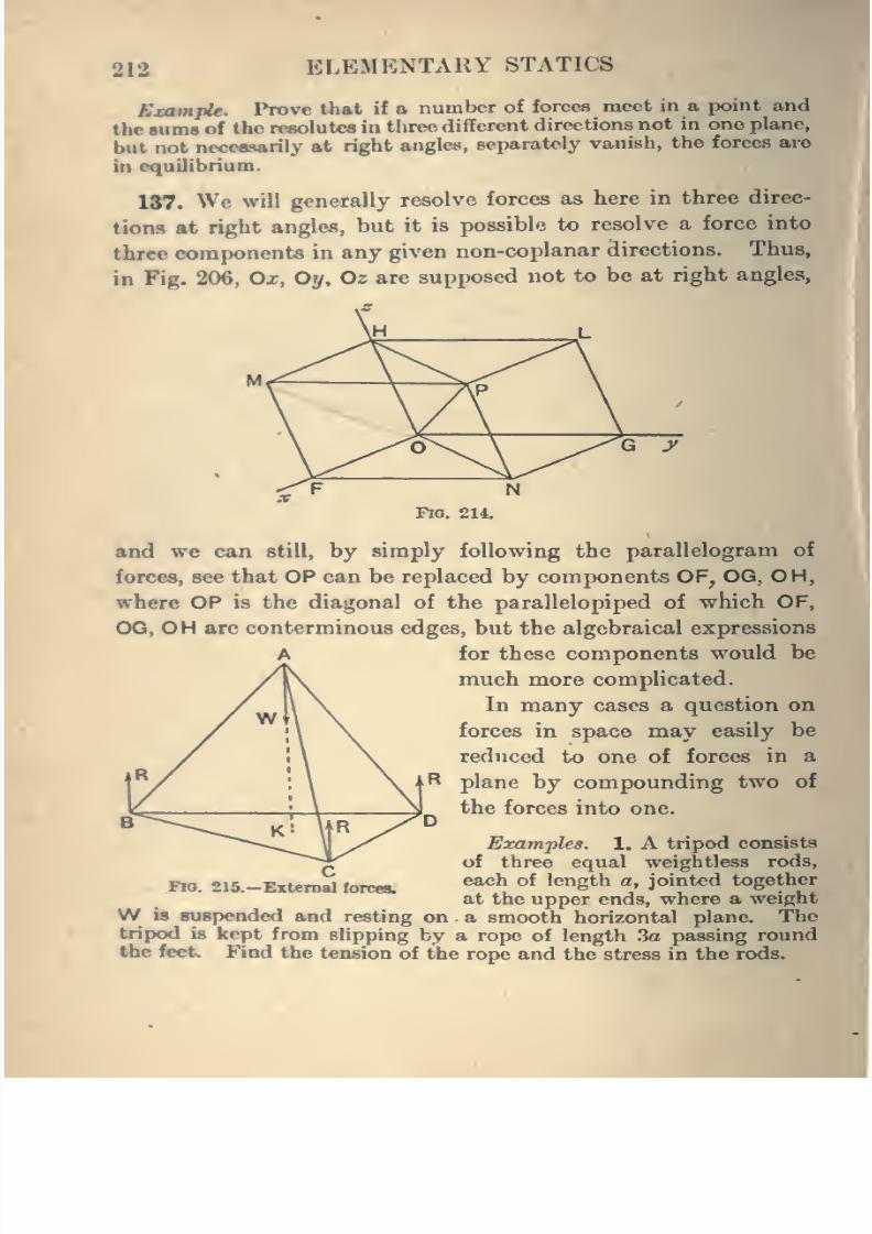
8/4/2019 Elementary Statics of 2 & Dimensions R.J.a. Barnard 1921
http://slidepdf.com/reader/full/elementary-statics-of-2-dimensions-rja-barnard-1921 224/272
212 ELEMENTARY STATICS
Example. Prove that if a number of forces meet in a point and
the sums of the rpsolutes in three different directions not in one plane,
but not necessarily at right angles, separately vanish, the forces are
in equilibrium.
187. We will generally resolve forces as here in three direc-
tions at right angles, but it is possible to resolve a force into
three components in any given non-coplanar directions. Thus,
in Fig. 206, Ox, Oy, Oz are supposed not to be at right angles,
\FlO, 214.
and we can still, by simply following the parallelogram of
forces, see that OP can be replaced by components OF, OG, OH,
where OP is the diagonal of the parallelopiped of which OF,
OG, OH are conterminous edges, but the algebraical expressions
for these components would be
much more complicated.
In many cases a question on
forces in space may easily be
reduced to one of forces in a
plane by compounding two of
the forces into one.
Examples. 1. A tripod consistsof three equal weightless rods,
each of length a, jointed together
at the upper ends, where a weight
W is suspended and resting on a smooth horizontal plane. Thetripod is kept from slipping by a rope of length 3a passing round
the feet. Find the tension of the rope and the stress in the rods.
I
Flo. 216.—External forces.
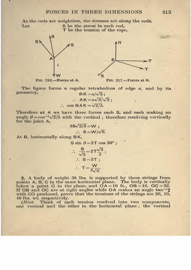
8/4/2019 Elementary Statics of 2 & Dimensions R.J.a. Barnard 1921
http://slidepdf.com/reader/full/elementary-statics-of-2-dimensions-rja-barnard-1921 225/272
FORCES IN THREE DIMENSIONS 213
As the rods are weightless, the stresses act along the rods.
Let S be the stress in each rod,
T be the tension of the rope.
YWFig. 216.—Forces at A.
^T
Fig. 217.—Forces at B.
The figure forms a regular tetrahedron of edge a, and by its
geometry,BK=a/v/3;
.-. AK=av/2/\/3;
.-. cosBAK=\/2/3.
Therefore at A we have three forces each S, and each making an
angle ^ = cos~V2/3 with the vertical ; therefore resolving vertically
for the joint A,
38^2/3 =W;
.-. S=W/V6.
At B, horizontally along B K,
Ssin^=2Tcos30°;
.'. -^=2T^;n/3 2
.-. S=3T;
• T = -^-
2. A body of weight 38 lbs. is supported by three strings from
points A, B, C in the same horizontal plane. The body is vertically
below a point O in the plane, and OA = 10 ft., 0B = 18, OC=32.If OB and OC are at right angles while OA makes an angle tan~'f
with CO produced, prove that the tensions of the strings are 26, 10,
10 lbs. wt. respectively.
{Hint. Think of each tension resolved into two components,
one vertical and the other in the horizontal plane ; the vertical
8/4/2019 Elementary Statics of 2 & Dimensions R.J.a. Barnard 1921
http://slidepdf.com/reader/full/elementary-statics-of-2-dimensions-rja-barnard-1921 226/272
214 ELEMENTARY STATICS
components balance the weight, those in the horizontal plane must
be in cqmHbrium.)
3. OA. OB, OC are axes mutually at right angles. P is equally
distant from the three planes OAB, etc. PL, PM, PN are the perpen-diculars from P on the three axes, and PR is the perpendicular on
the plane AOB. If PL, PM, PR, LR, MR, NR are weightless bars
attaching P to fixed points L, M, N, find the stresses in the bars when
a force F acts at P parallel to OB.
4. OA, OB, OC are axes mutually at right angles. CA, CB, COare weightless bars jointed together at C and to fixed points A, B, O.
A force acts at C, whose components are X, Y, Z. Find the stresses
in the bars.
5. A weightW is supported at a point O by a tripod of three rods,
OA, OB, OC, resting on the ground at A, B, C. The vertical through
O meet« the ground at N, and AN meets BC in D. Prove that the
stiCM in OA is W . ND . OA/AD . ON.
6. In the tripod of Example 5, O A =7 ft., OB =0C =5 ft., ON =\/24
ft., and the angles ANB, BNC, CNA are all 120°. Calculate by the
method of Example 5 the stresses in the bars if the weight supported
is 100 lbs.
7. An electric wire, approximately horizontal, and having a
tension of 100 lbs., passes round a post 20 ft. high, the two portions
making an angle 150° with one another. A stay 25 ft. long is fixed
to the top of the post -and to the ground. What should be the
tension of the stay so that there should be no horizontal stress on the
post?
8/4/2019 Elementary Statics of 2 & Dimensions R.J.a. Barnard 1921
http://slidepdf.com/reader/full/elementary-statics-of-2-dimensions-rja-barnard-1921 227/272
CHAPTER XIV.
ANY FORCES IN THREE DIMENSIONS.
138. To discover tlie conditions of equilibrium when a
number of forces act at any points of a body in three dimensions,
we shall follow the same method as before by simplifying the
system of forces, making use of the results of Chapter IV.
We have, however, to examine first into the composition of
couples in different planes. We saw in Chapter IV. that
couples in the same or parallel planes compound together by
simply adding their moments. Now we will have to deal with
couples in different planes, and the question arises at once,
" Can couples in different planes be compounded together in
any way ?"
We shall be able to shew that we can represent couples by
means of straight lines as we did forces. For the plane in
which a couple lies may be sufficiently indicated by a straight
line perpendicular to the plane, for it does not matter whether
the couple is in a given plane or in any parallel one. Also the
magnitude of the moment of the couple, which, it will be
remembered, is the only other thing of consequence about the
couple, may be represented by the length of this line, so thatwe have a line of a certain length and direction completely
representing the action of the couple. The couple is thus a
vector quantity, and may be expected to obey the vector
laws.
215
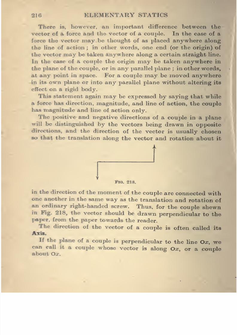
8/4/2019 Elementary Statics of 2 & Dimensions R.J.a. Barnard 1921
http://slidepdf.com/reader/full/elementary-statics-of-2-dimensions-rja-barnard-1921 228/272
216 ELEMENTARY STATICS
There is, however, an important difference between the
vector of a force and the vector of a couple. In the case of a
force the vector may be thought of as placed anywhere along
the line of action ; in other words, one end (or the origin) of
the vector may be taken anywhere along a certain straight line.
In the case of a couple the origin may be taken anywhere in
the plane of the couple, or in any parallel plane ; in other words,
at any j)oint in space. For a couple may be moved anywhere
in its own plane or into any parallel plane without altering its
effect
on arigid
body.This statement again may be expressed by saying that while
a force has direction, magnitude, and line of action, the couple
has magnitude and line of action only.
The positive and negative directions of a couple in a plane
will be distinguished by the vectors being drawn in opposite
directions, and the direction of the vector is usually chosen
80 that the translation along the vector and rotation about it
FlO. 218.
in the direction of the moment of the couple are connected with
one another in the same way as the translation and rotation of
an ordinary right-handed screw. Thus, for the couple shewn
in Fig. 218, the vector should be drawn perpendicular to the
paper, from the paper towards the reader.
The direction of the vector of a couple is
often called itsAxis.
If the plane of a couple is perpendicular to the line Ox, wecan call it a couple whose vector is along Oa;, or a couple
about Ox.
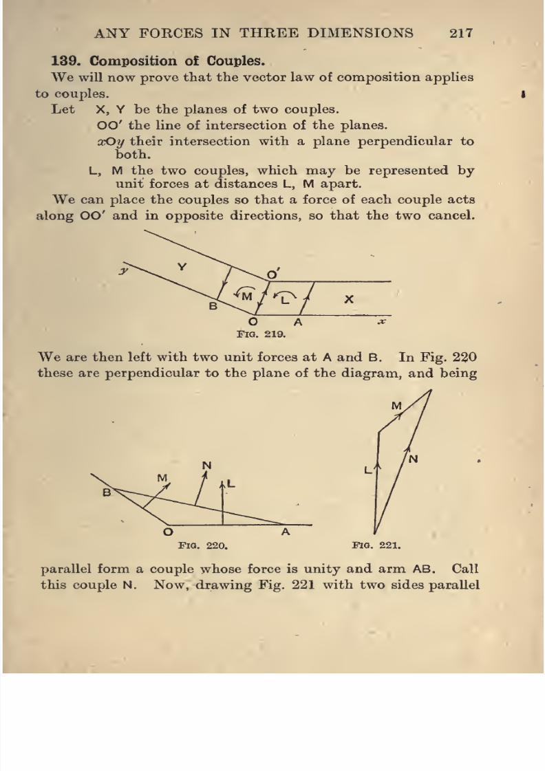
8/4/2019 Elementary Statics of 2 & Dimensions R.J.a. Barnard 1921
http://slidepdf.com/reader/full/elementary-statics-of-2-dimensions-rja-barnard-1921 229/272
ANY FORCES IN THREE DIMENSIONS 217
139. Composition of Couples.
We will now prove that the vector law of composition applies
to couples.
Let X, Y be the planes of two couples.
00' the line of intersection of the planes.
xOy their intersection with a plane perpendicular to
both.
L, M the two couples, which may be represented by
unit forces at distances L, M apart.
We can place the couples so that a force of each couple acts
along 00' and in opposite directions, so that the two cancel.
AFig. 219.
We are then left with two unit forces at A and B. In Fig. 230
these are perpendicular to the plane of the diagram, and being
FlQ. 220. Fig. 221.
parallel form a couple whose force is unity and arm AB. Call
this couple N. Now, drawing Fig. 221 with two sides parallel
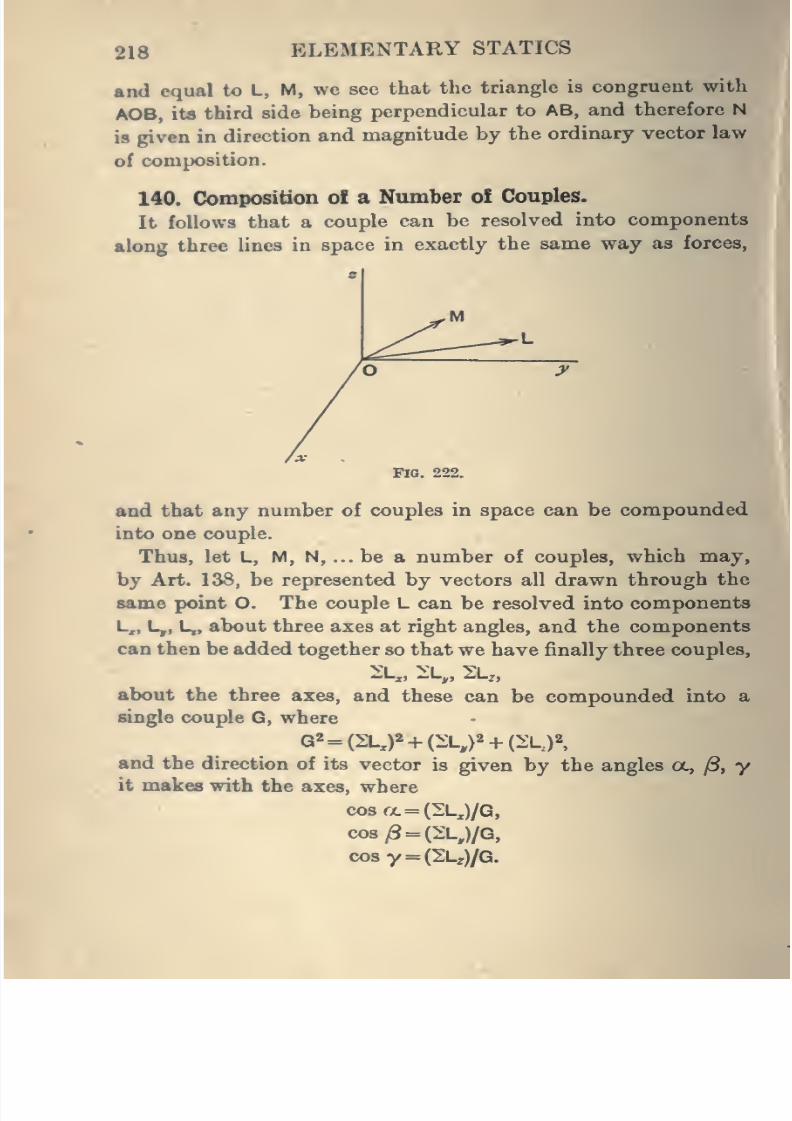
8/4/2019 Elementary Statics of 2 & Dimensions R.J.a. Barnard 1921
http://slidepdf.com/reader/full/elementary-statics-of-2-dimensions-rja-barnard-1921 230/272
218 ELEMENTARY STATICS
and equal to L, M, we see that the triangle is congruent with
AOB, ita third side being perpendicular to AB, and therefore N
is given in direction and magnitude by the ordinary vector law
of composition.
140. Composition ol a Number o£ Couples.
It follows that a couple can be resolved into components
along three lines in space in exactly the same way as forces,
Fia. 222.
and that any number of couples in space can be compounded
into one couple.
Thus, let L, M, N, ... be a number of couples, which may,
by Art. 138, be represented by vectors all drawn through the
same point O. The couple L can be resolved into components
L,, L,, L,, about three axes at right angles, and the components
can then be added together so that we have finally three couples,
"-XJ •"'-yj ^'-Zt
about the three axes, and these can be compounded into a
single couple G, where
and the direction of its vector is given by the angles a., jS, yit makes with the axes, where
cosa= (2L,)/G,
co8/3 = (2;l,)/Q,
cosy = (2Lz)/Q.
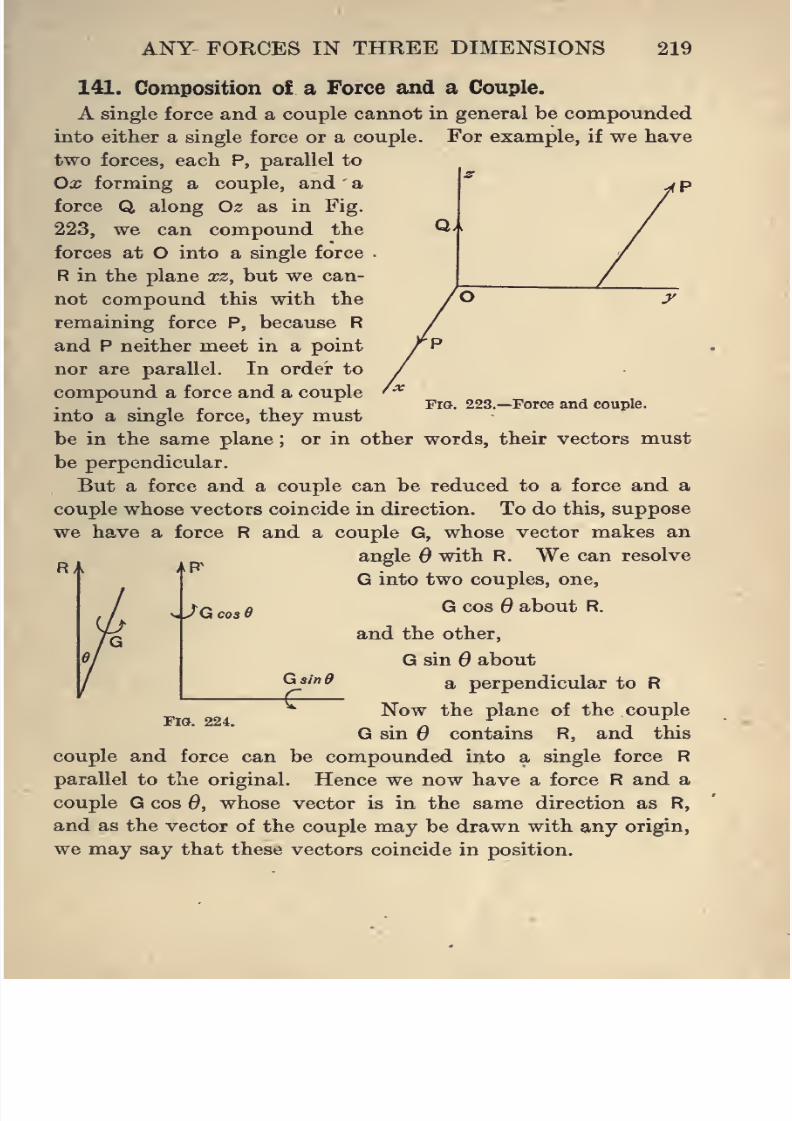
8/4/2019 Elementary Statics of 2 & Dimensions R.J.a. Barnard 1921
http://slidepdf.com/reader/full/elementary-statics-of-2-dimensions-rja-barnard-1921 231/272
ANY FORCES IN THREE DIMENSIONS 219
Qm
y
Fig. 223.—Force and couple.
141. Composition of a Force and a Couple.
A single force and a couple cannot in general be compounded
into either a single force or a couple. For example, if we have
two forces, each P, parallel to
Ox forming a couple, and a
force Q along Oz as in Fig.
223, we can compound the
forces at O into a single force
R in the plane xz, but we can-
not compoundthis
withthe
remaining force P, because R
and P neither meet in a point
nor are parallel. In order to
compound a force and a couple
into a single force, they must
be in the same plane ; or in other words, their vectors must
be perpendicular.
But a force and a couple can be reduced to a force and a
couple whose vectors coincide in direction. To do this, suppose
we have a force R and a couple G, whose vector makes an
angle Q with R. We can resolve
G into two couples, one,
G cos Q about R.
and the other,
G sin Q about
a perpendicular to R
Now the plane of the couple
G sin Q contains R, and this
couple and force can be compounded into a single force R
parallel to the original. Hence we now have a force R and a
couple G cos Q, whose vector is in the same direction as R,
and as the vector of the couple may be drawn with any origin,
we may say that these vectors coincide in position.
AR
V y G coi
Gainff
Fig. 224.
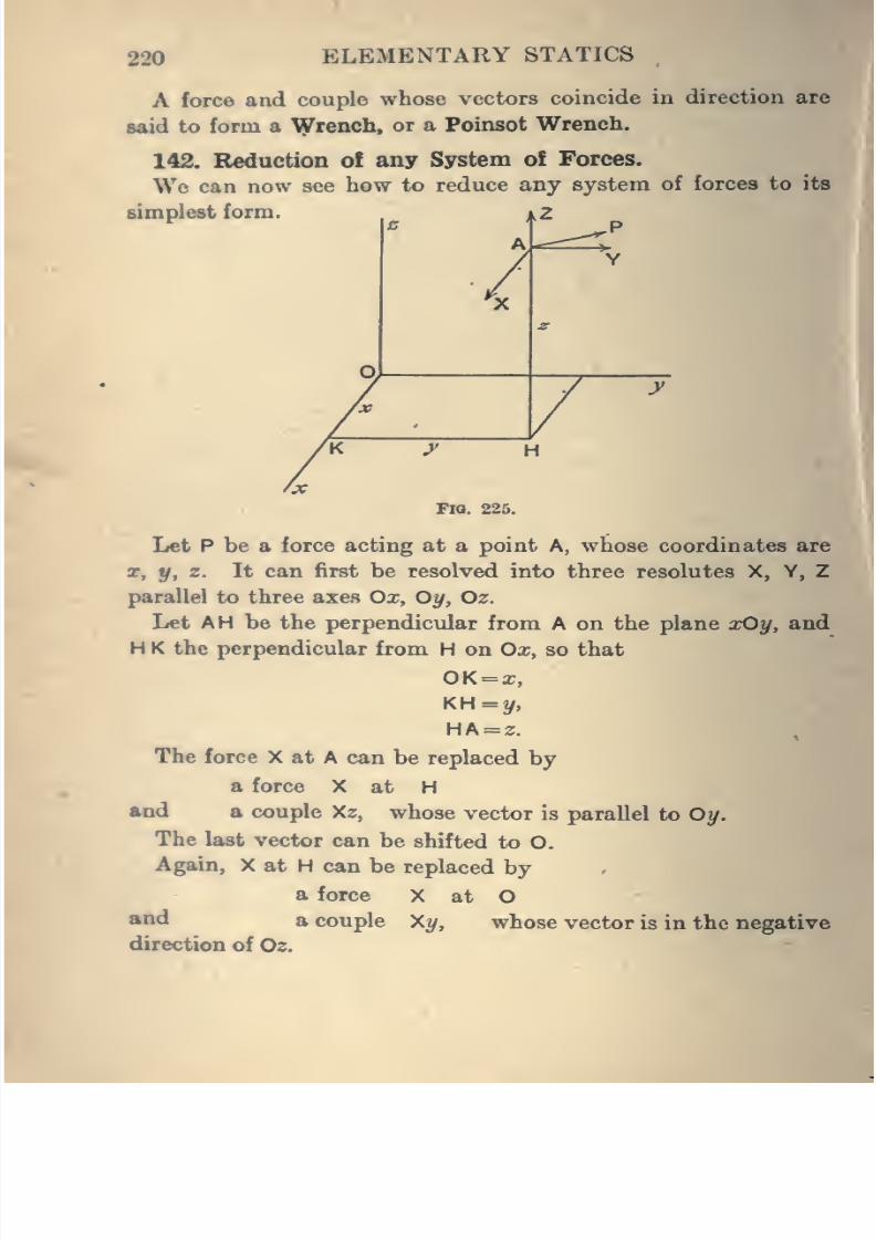
8/4/2019 Elementary Statics of 2 & Dimensions R.J.a. Barnard 1921
http://slidepdf.com/reader/full/elementary-statics-of-2-dimensions-rja-barnard-1921 232/272
220 ELEMENTARY STATICS
A force and couple whose vectors coincide in direction are
said to form a yiTrench, or a Poinsot Wrench.
142. Redaction of any System ofForces.
We can now see how to reduce any system of forces to its
simplest form.
\FlO. 225.
Let P be a force acting at a point A, whose coordinates are
X, y, z. It can first be resolved into three resolutes X, Y, Z
parallel to three axes Ox, Oy, Oz.
Let AH be the perpendicular from A on the plane xOy, and
H K the perpendicular from H on Ox, so that
OK = x,
KH=y,
HA = 2.
The force X at A can be replaced by
a force X at H
and a couple Xz, whose vector is parallel to Oy.
The last vector can be shifted to O.
Again, X at H can be replaced by
a force X at O*°** a couple Xy, whose vector is in the negative
direction of Oz.
8/4/2019 Elementary Statics of 2 & Dimensions R.J.a. Barnard 1921
http://slidepdf.com/reader/full/elementary-statics-of-2-dimensions-rja-barnard-1921 233/272
ANY FORCES IN THREE DIMENSIONS 221
Thus we have now replaced the original X by
a force X at O along Ox,
acouple Xz about Oy,
and a couple - X?/ about Oz.
Similarly, we can replace Y by
a force Y at O along Oy.
a couple Ya; about Oz,
and a couple - Yz about Ox,
and we can replace Z by
a force Z at O along Oz,
a couple Zy about Ox,
and a couple -Zx about Oy.
Adding these together, the force P at A is equivalent to
forces X, Y, Z at O along the axes,
and couples Zy - Yz, Xz - Zx, \x - Yy about the axes.
If we have any system of forces we can do the same with
each, and so reduce the whole to
forces 2X, 2Y, ^Z along the axes,
and couples 2(Z?/-Yz), ^(Xz-Za;), 1{yx-Xy) about the
axes.
The forces can now be compounded into a single force
R at O, and the couples into one couple, G.
Thus, in any case a system of forces may be reduced to a
single force at any assumed point and a couple. In general,
these cannot be reduced further except to a Poinsot Wrench,
but in special cases either the single force or the couple, or
both, may vanish. Further, as in the cas^of forces in a plane,it will be seen that the force will be the same in magnitude
and direction whatever point O is taken as base, but both
magnitude and direction of the couple will vary with different
bases.
8/4/2019 Elementary Statics of 2 & Dimensions R.J.a. Barnard 1921
http://slidepdf.com/reader/full/elementary-statics-of-2-dimensions-rja-barnard-1921 234/272
222 ELEMENTARY STATICS
The possibilities, therefore, for the reduction of a system of
forces are
(i) A force and a couple,
(ii) A force only.
(Hi) A couple only,
(iv) Nothing at all, or equilibrium.
148. Conditions for Equilibrium.
It will be seen now that for equilibrium both the resultant
force and the resultant couple must be zero, and these involve
that the three components in each case are zero, and we -
therefore have six conditions,
2X=0,
2Y = 0,
2Z=0,
l{Zy-yz) = 0,
l(Xz-Zx)=0,
2(Yx-Xt/)=0.
Examples. 1. Prove algebraically that if these equations are
satisfied, and if a new point O' is chosen as origin instead of O, the
idz expressions there also will vanish.
2. Prove algebraically that if the forces reduce to a couple the
components ofthe couple are the same for all base points.
144. Moment of a Force about a Line.
In dealing with forces in one plane we spoke only of the
moment of a force about a point. It can be shewn (see
Elementary Dynamics, Art. 180) that the moment is a measure
of the tendency of the force to cause rotation about an axis
through the point perpendicular to the plane containing theforce and the point.
In dealing with forces in different directions in space it is
necessary to examine the turning power of a force about any
line in space . We can deduce satisfactory methods of measuring
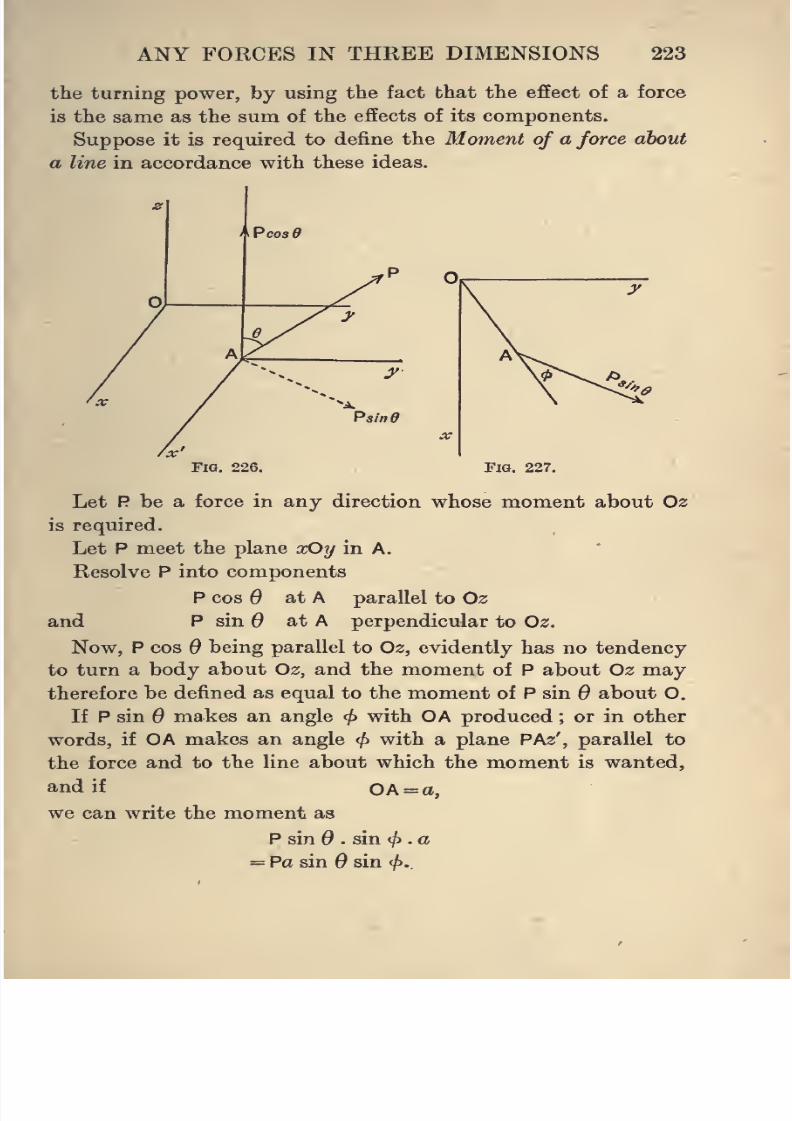
8/4/2019 Elementary Statics of 2 & Dimensions R.J.a. Barnard 1921
http://slidepdf.com/reader/full/elementary-statics-of-2-dimensions-rja-barnard-1921 235/272
ANY FORCES IN THREE DIMENSIONS 223
the turning power, by using the fact that the effect of a force
is the same as the sum of the effects of its components.
Suppose it is required to define the Moment of a force about
a line in accordance with these ideas.
ma. 226. Fig. 227.
Let P be a force in any direction whose moment about Oz
is required.
Let P meet the plane xOy in A.
Resolve P into components
P cos 6 at A parallel to Oz
and P sin 6 at A perpendicular to Oz.
Now, P cos 6 being parallel to Oz, evidently has no tendency
to turn a body about Oz, and the moment of P about Oz may
therefore be defined as equal to the moment of P sin 6 about O.
If P sin 6 makes an angle ^ with OA produced ; or in other
words, if OA makes an angle ^ with a plane PAz', parallel to
the force andto the line about which the
momentis wanted,
and if OA = a,
we can write the moment as
P sin . sin </> . a
= Pa sin 6 sin </>.
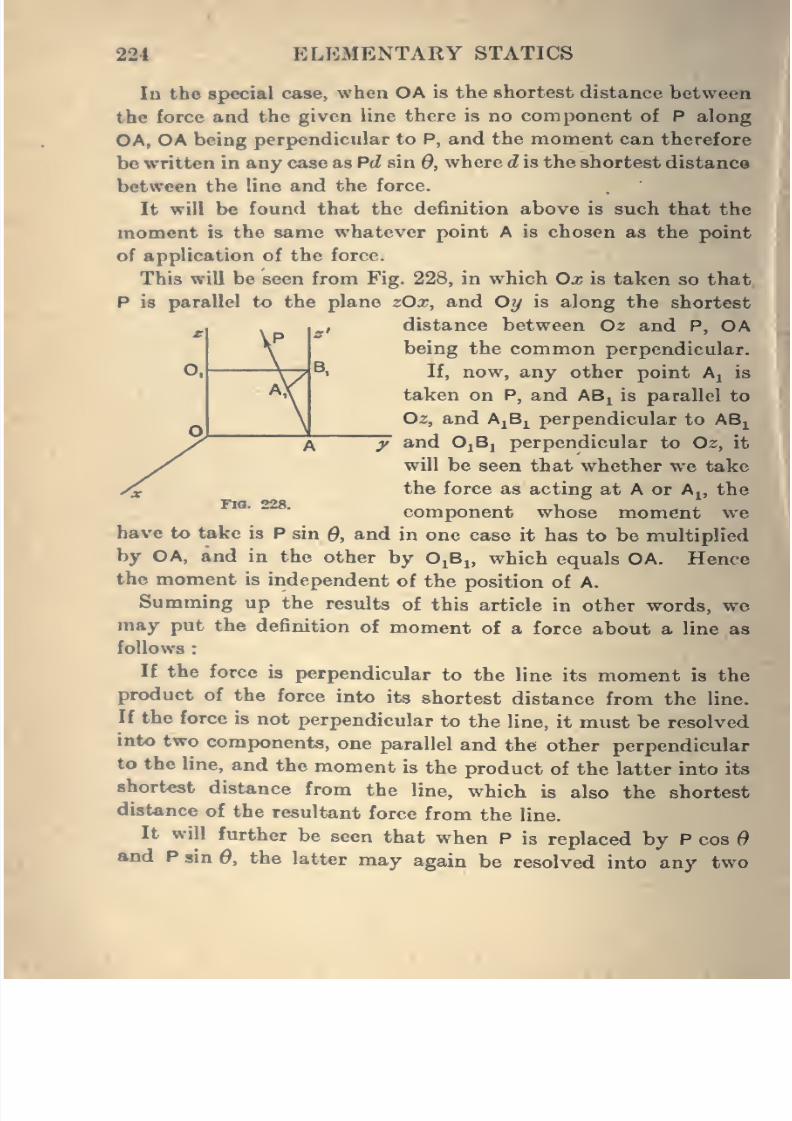
8/4/2019 Elementary Statics of 2 & Dimensions R.J.a. Barnard 1921
http://slidepdf.com/reader/full/elementary-statics-of-2-dimensions-rja-barnard-1921 236/272
M\'
gl
0. \ B
\''i
\
224 ELEMENTARY STATICS
In the special case, when OA is the shortest distance between
the force and the given line there is no component of P along
OA, OA being perpendicular to P, and the moment can therefore
be written in any case as Pd, sin 0, where d is the shortest distance
between the line and the force.
It will be found that the definition above is such that the
moment is the same whatever point A is chosen as the point
of application of the force.
This will be seen from Fig. 228, in which Ox is taken so that
P is parallel to the plane zOx, and Oy is along the shortest
distance between Oz and P, OA
being the common perpendicular.
If, now, any other point A^ is
taken on P, and ABi is parallel to
02, and AjBi perpendicular to AB^
and OjBj perpendicular to O2, it
will be seen that whether we take
the force as acting at A or A^, the
component whose moment we
have to take is P sin Q, and in one case it has to be multiplied
by OA, and in the other by O^B^, which equals OA. Hence
the moment is independent of the position of A.
Summing up the results of this article in other words, we
may put the definition of moment of a force about a line as
follows
If the force is perpendicular to the line its moment is the
product of the force into its shortest distance from the line.
If the force is not perpendicular to the line, it must be resolved
into two components, one parallel and the other perpendicular
to the line, and the moment is the product of the latter into its
shortest distance from the line, which is also the shortest
distance of the resultant force from the line.
It will further be seen that when P is replaced by P cos dand P sin 0, the latter may again be resolved into any two
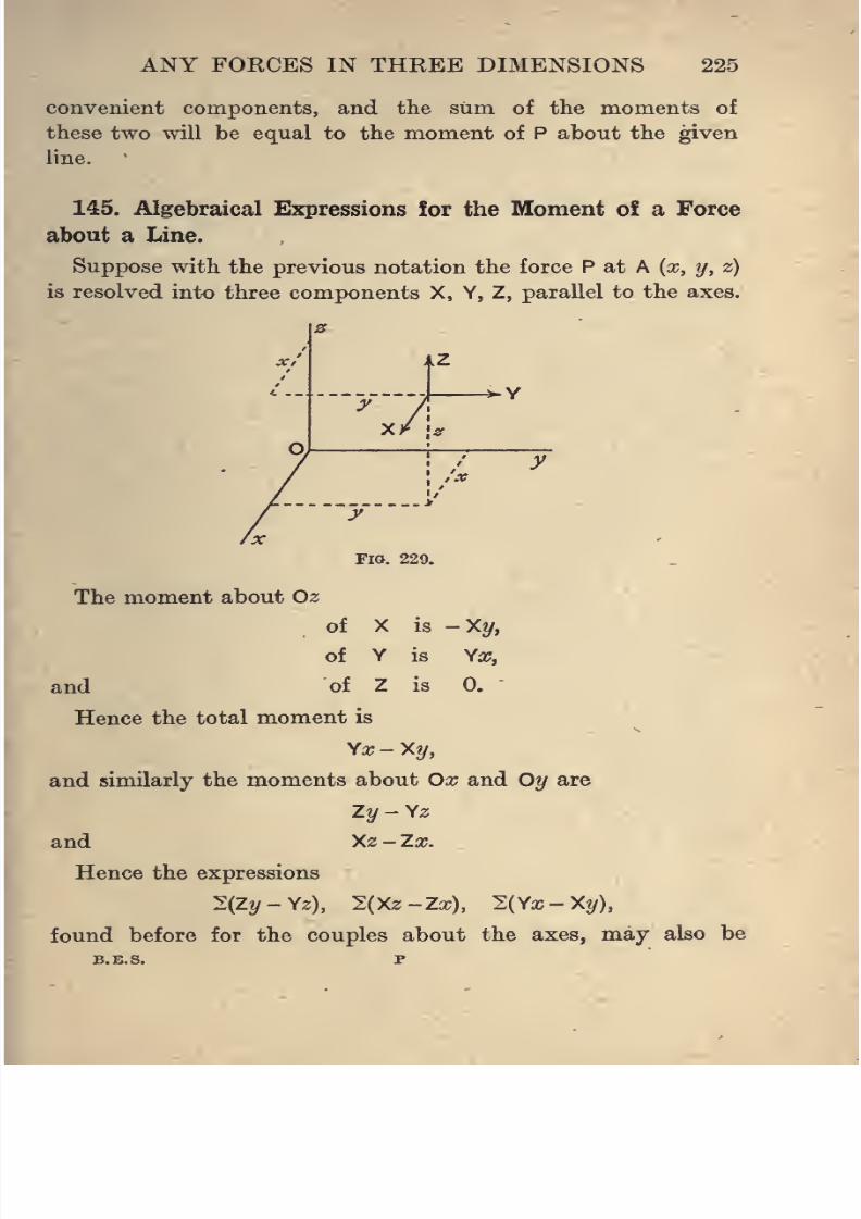
8/4/2019 Elementary Statics of 2 & Dimensions R.J.a. Barnard 1921
http://slidepdf.com/reader/full/elementary-statics-of-2-dimensions-rja-barnard-1921 237/272
ANY FORCES IN THREE DIMENSIONS 225
convenient components, and the sum of the moments of
these two will be equal to the moment of P about the given
line.
145. Algebraical Expressions for the Moment of a Force
about a Line.
Suppose with the previous notation the force P at A {x, y, z)
is resolved into three components X, Y, Z, parallel to the axes.
The moment about Oz
of X is -Xy,
of Y is Yx,
and of Z is 0.
Hence the total moment is
Vx-Xy,
and similarly the moments about Ox and Oy are
Zy-\z
and Xz-Zx.
Hence the expressions
2{Zy-yz), 2(Xz-Zic), i:{yx-xy),
found before for the couples about the axes, may also be
B.E.S. p
8/4/2019 Elementary Statics of 2 & Dimensions R.J.a. Barnard 1921
http://slidepdf.com/reader/full/elementary-statics-of-2-dimensions-rja-barnard-1921 238/272
226 ELEMENTARY STATICS
called the sums of the moments of the forces about the
axes.
148. The conditions for equilibrium may therefore be
expressed as follows
A system offorces is in equilibrium if the sums of the resolved
parts oftheforces along any three lines at right angles are separately
zero, arul the stims of the moments of the forces about these lines
are also separately zero.
It will readily beseen, however, that the three lines chosen
for resolving along need not necessarily be the same as the
three about which moments are taken, nor need either set,
in fact, consist necessarily of lines at right angles to one another,
but may be in any directions, provided they are not in one
plane, but it is almost always most convenient to take them
at right angles.
147. Resultant o! Parallel Forces in Three Dimensions.
A number of j)arallel forces can be compounded two at a
time, and will therefore always reduce either to a single force
or a couple. If they reduce to a single force the resultant
will be equal to their algebraic sum, and the moment of the
resultant about any line will be equal to the sum of the moments
of the separate forces.
Suppose the forces are P^, P^, P3, ... parallel to O2, and that
they meet the plane xOy in points whose co-ordinates are
*i» yi 5 ^t yj, •••, and suppose the resultant R meets this plane
in X, y.
Then R=2P.
Also taking moments about the line Oy,
Rx = 2Px;
. - 2Px• ^ = -vp
exactly as in Art. 33 for forces in one plane.
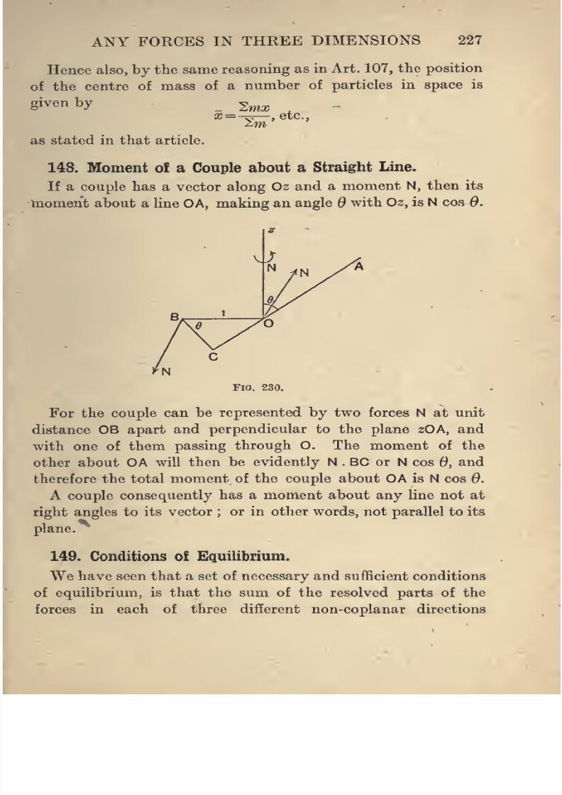
8/4/2019 Elementary Statics of 2 & Dimensions R.J.a. Barnard 1921
http://slidepdf.com/reader/full/elementary-statics-of-2-dimensions-rja-barnard-1921 239/272
8/4/2019 Elementary Statics of 2 & Dimensions R.J.a. Barnard 1921
http://slidepdf.com/reader/full/elementary-statics-of-2-dimensions-rja-barnard-1921 240/272
228 ELEMENTARY STATICS
should separately vanish, and that the sums of the moments
about three different non-coplanar lines should qpparately
vanish.
It may be useful to examine this statement in another way.
It is proved in Art. 142 that a system of forces may reduce
to either(^^ ^ f^^^.^ and a couple,
(ii) A force only,
(iii) A couple only,
(iv) Zero.
If the above six conditions hold, we see that the resultant
force must be zero, for if there were a resultant (which it will
be remembered is the same whatever base point is taken),
it would require to be at right angles to each of the three
directions, which is impossible, as the three, are not in one plane.
Hence the alternatives (i) and (ii) are impossible. We then
see that the remaining conditions shew that (iii) is impossible,
for if the sum of the moments of the forces about three lines
are separately zero, and the forces reduced to a couple, this
couple would have zero moment about each of the three lines,
and these three lines would therefore have to be all parallel
to the plane of the couple, which is contrary to the supposition
that they are concurrent and non-coplanar. Hence the forces
must be in equilibrium.
It will also readily be seen that the six conditions are
necessary. For if five only of these were given, the forces
might reduce to a single force or a couple .according to what
five conditions held.
Thus, if the sums of the resolutes along Ox and Oy ai^ zero,
and the sums of the moments about the three lines are zero,
80 that we have five conditions only, all these conditions would
be satisfied if the forces reduced to a single resultant along Oz.
Again, if the sums of the resolutes along the three axes are
zero, and the sums of the moments about Ox and Oy zero,
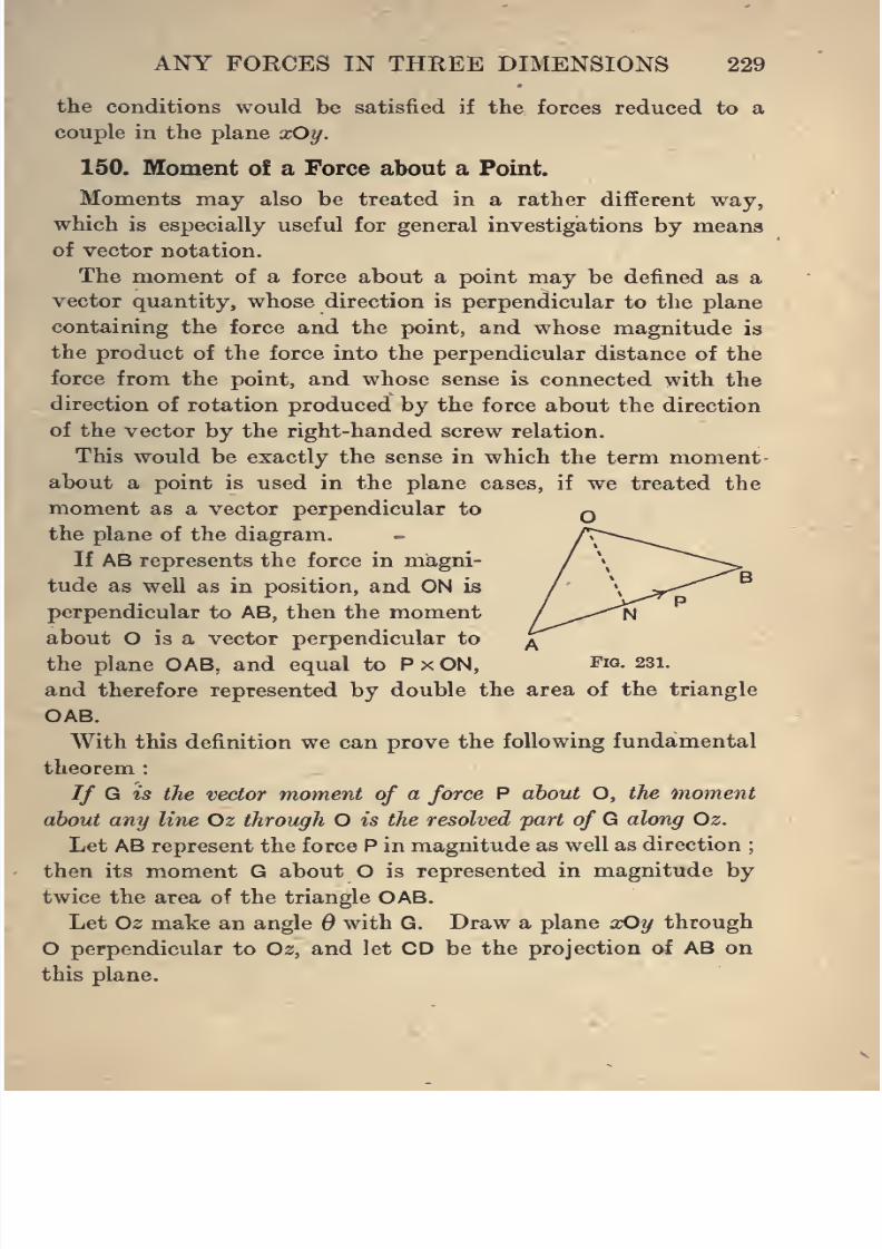
8/4/2019 Elementary Statics of 2 & Dimensions R.J.a. Barnard 1921
http://slidepdf.com/reader/full/elementary-statics-of-2-dimensions-rja-barnard-1921 241/272
ANY FORCES IN THREE DIMENSIONS 229
the conditions would be satisfied if the forces reduced to a
couple in the plane aOy.
150. Moment of a Force about a Point.
Moments may also be treated in a rather different way,
which is especially useful for general investigations by means
of vector notation.
The moment of a force about a point may be defined as a
vector quantity, whose direction is perpendicular to the plane
containing the force and the point, and whose magnitude is
the product of the force into the perpendicular distance of the
force from the point, and whose sense is connected with the
direction of rotation produced by the force about the direction
of the vector by the right-handed screw relation.
This would be exactly the sense in which the term moment
about a point is used in the plane cases, if we treated the
moment as a vector perpendicular to
the plane of the diagram.
If AB represents the force in magni-
tude as well as in position, and ON is
perpendicular to AB, then the moment
about O is a vector perpendicular to
the plane OAB, and equal to P x ON, Fig. 231.
and therefore represented by double the area of the triangle
OAB.
With this definition we can prove the following fundamental
theorem :
// G is the vector moment of a force P about O, the moment
about any line Oz through O is the resolved part of G along Oz.
Let AB represent the force P in magnitude as well as direction;
then its moment G about O is represented in magnitude by
twice the area of the triangle OAB.
Let Oz make an angle 6 with G. Draw a plane xOy through
O perpendicular to Oz, and let CD be the projection of AB on
this plane.
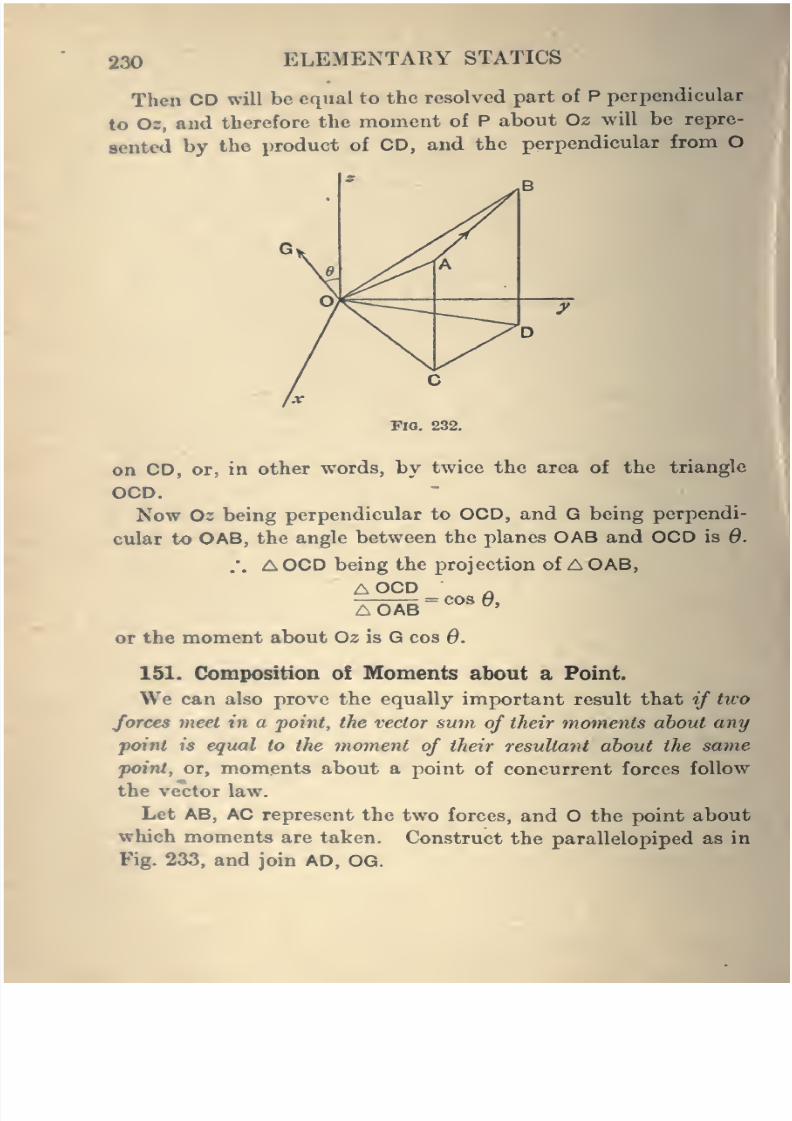
8/4/2019 Elementary Statics of 2 & Dimensions R.J.a. Barnard 1921
http://slidepdf.com/reader/full/elementary-statics-of-2-dimensions-rja-barnard-1921 242/272
230 ELEMENTARY STATICS
Then CD will be equal to the resolved part of P perpendicular
to Oz, and therefore the moment of P about Oz will be repre-
sented by the product of CD, and the perpendicular from O
^1Fig. 232.
on CD, or, in other words, by twice the area of the triangle
OCD.
Now 02 being perpendicular to OCD, and G being perpendi-
cular to OAB, the angle between the planes OAB and OCD is 6.
.'. A OCD being the projection of A OAB,
A OCD „= cos 0,
A OAB ^'
or the moment about Oz is G cos 0.
151. CJomposition of Moments about a Point.
We can also prove the equally important result that if two
forces meet in a point, the vector sum of their moments about any
point is equal to the moment of their resultant about the same
point, or, moments about a point of concurrent forces followthe vector law.
Let AB, AC represent the two forces, and O the point about
which moments are taken. Construct the parallelopiped as in
Fig. 233, and join AD, OG.
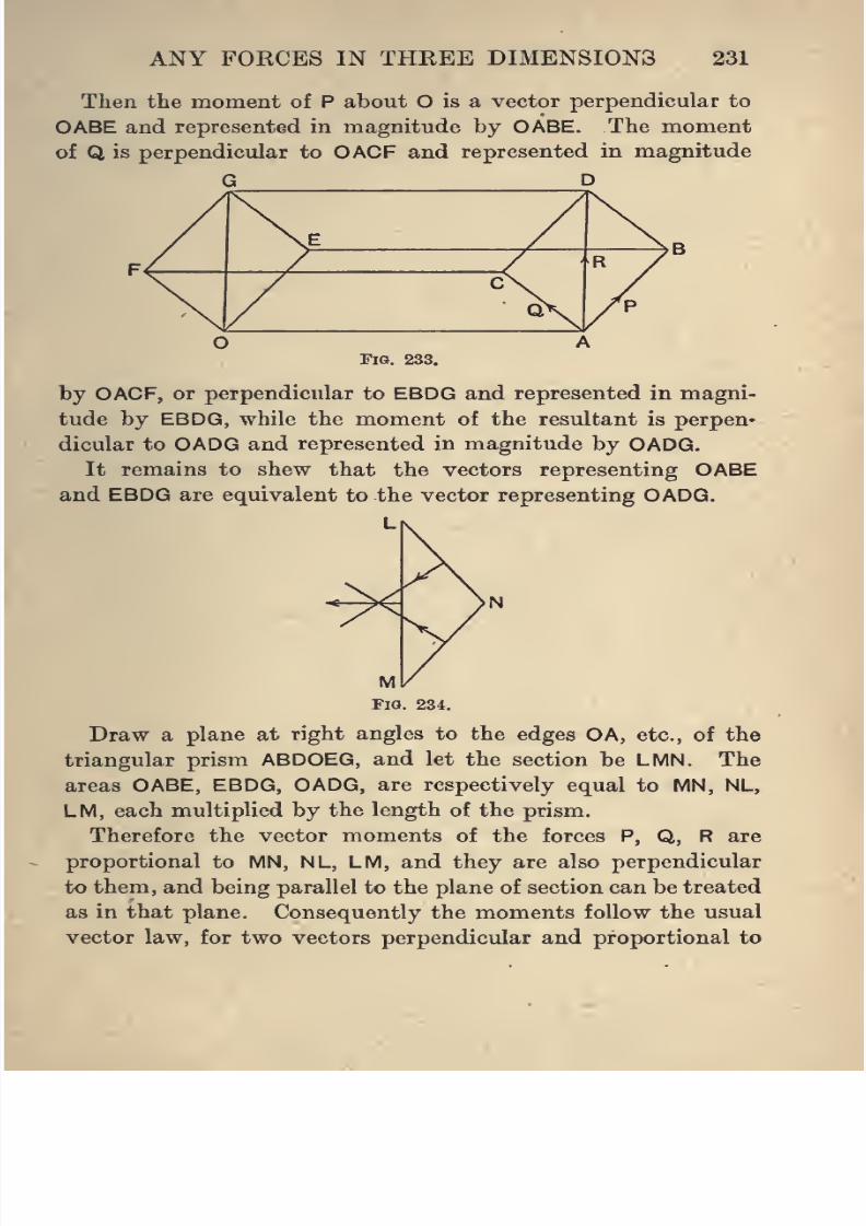
8/4/2019 Elementary Statics of 2 & Dimensions R.J.a. Barnard 1921
http://slidepdf.com/reader/full/elementary-statics-of-2-dimensions-rja-barnard-1921 243/272
ANY FORCES IN THREE DIMENSIONS 231
Then the moment of P about O is a vector perpendicular to
OABE and represented in magnitude by OABE. The moment
of Q is perpendicular to OACF and represented in magnitude
G D
Fig. 233.
by OACF, or perpendicular to EBDG and represented in magni-
tude by EBDG, while the moment of the resultant is perpen-
dicular to OADG and represented in magnitude by OADG.
It remains to shew that the vectors representing OABE
and EBDG are equivalent to the vector representing OADG.
Draw a plane at right angles to the edges OA, etc., of the
triangular prism ABDOEG, and let the section be LMN. The
areas OABE, EBDG, OADG, are respectively equal to MN, NL,
LM, each multiplied by the length of the prism.
Therefore the vector moments of the forces P, Q, R areproportional to MN, NL, LM, and they are also perpendicular
to them, and being parallel to the plane of section can be treated
as in that plane. Consequently the moments follow the usual
vector law, for two vectors perpendicular and proportional to
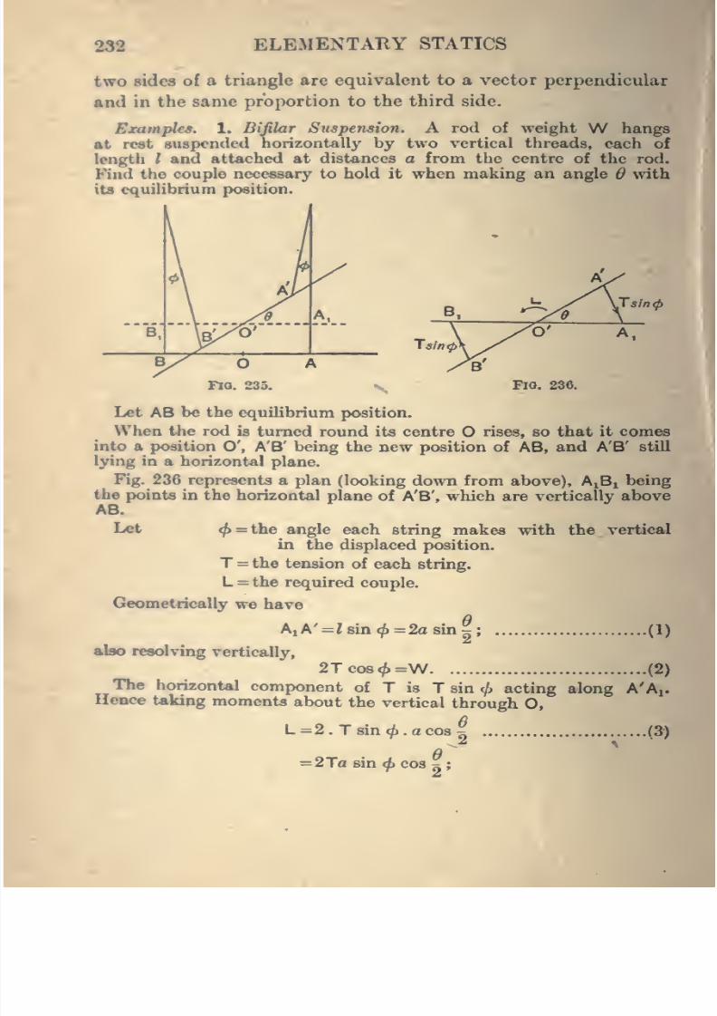
8/4/2019 Elementary Statics of 2 & Dimensions R.J.a. Barnard 1921
http://slidepdf.com/reader/full/elementary-statics-of-2-dimensions-rja-barnard-1921 244/272
232 ELEMENTARY STATICS
two sides of a triangle are equivalent to a vector perpendicular
and in the same proportion to the third side.
ExampUs. 1. Bifilar Suspension. A rod of weight W hangs
at rest suspended horizontally by two vertical threads, each of
length / and attached at distances a from the centre of the rod.
Find the couple necessary to hold it when making an angle 6 with
its equihbrium position.
B,
Tsintp
Tain <()
O'
Fig. 236.
Let AB be the equiUbrium position.When the rod is turned round its centre O rises, so that it comes
into a position O', A'B' being the new position of AB, and A'B' still
lying in a horizontal plane.
Fig. 236 represents a plan (looking down from above), AjBi being
the points in the horizontal plane of A'B', which are vertically aboveAB.
I^t ^=the angle each string makes with the vertical
in the displaced position.
T =the tension of each string.
L =the required couple.
Geometrically we have
eA, A' = Z sin <^ =2a sin
;
(1)
(2)
also resolving vertically,
2Tco8</)=W
The horizontal component of T is T sin <!> acting along A'Aj.
Hence taking moments about the vertical through O,
eL=2. T sin ^.a cos
=2Tasin^cos^;
(3)
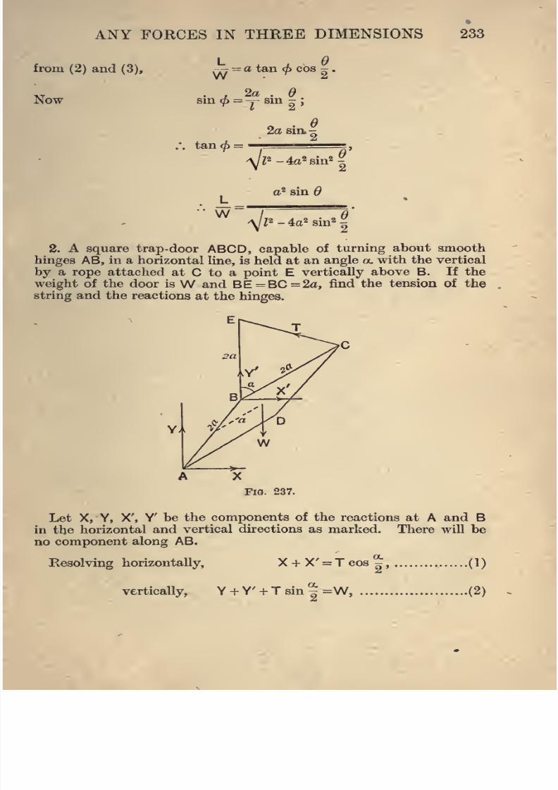
8/4/2019 Elementary Statics of 2 & Dimensions R.J.a. Barnard 1921
http://slidepdf.com/reader/full/elementary-statics-of-2-dimensions-rja-barnard-1921 245/272
from (2) and (3),
Now
ANY FOKCES IN THEEE DIMENSIONS
L
233
,., =a tan </> cos jr.W "^2
. , 2a . eBin <p = -7 sin -
;
tan(^:
2a sin.^
V-^2 - 4a^ sin^
W ^l' 4<i^ sin^^
2. A square trap-door ABCD, capable of turning about smooth
hinges AB, in a horizontal line, is held at an angle a. with the vertical
by a rope attached at C to a point E vertically above B. If the
weight of the door is W and BE =BC =2a, find the tension of the
string and the reactions at the hinges.
Fia. 237.
Let X, Y, X', Y' be the components of the reactions at A and Bin the horizontal and vertical directions as marked. There will be
no component along AB.
Resolving horizontally,
vertically,
X + X' = Tcos2'
Y + Y' + Tsin|=W,
(1)
.(2)
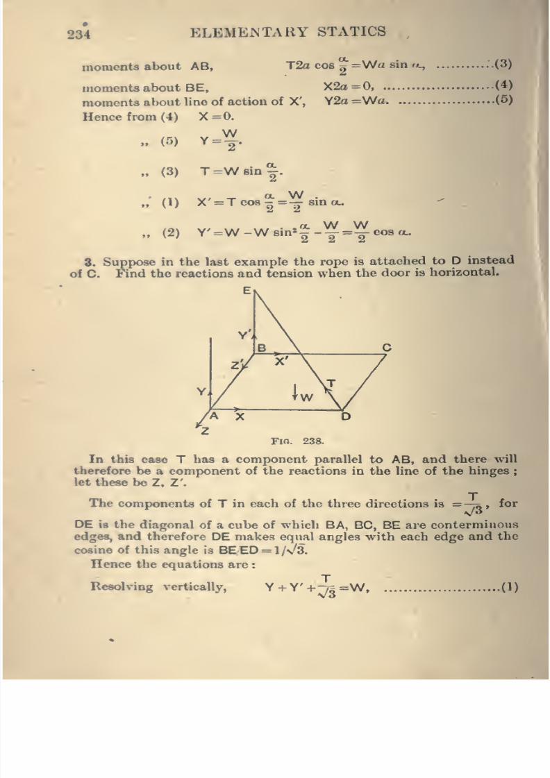
8/4/2019 Elementary Statics of 2 & Dimensions R.J.a. Barnard 1921
http://slidepdf.com/reader/full/elementary-statics-of-2-dimensions-rja-barnard-1921 246/272
234 ELEMEJSTARY STATICS
momenta about AB, T2o cos ^ =Wa sin <k,
moments about BE, X2a=0,
moments about line of action of X', Y2o =WaHence from (4) X=0.
.(3)
(4)
.(5)
(5)
(3)
(1)
(2)
WY =—
.
T =W sin ^.
X =T cos - =— sin ou
Y' =W -W sin*^ -Y =Y cos OL.
8. Suppose in the last example the rope is attached to D instead
of C. Find the reactions and tension when the door is horizontal.
Fio. 238.
In this case T has a component parallel to AB, and there will
therefore be a component of the reactions in the line of the hinges
let these be Z, Z'.
Hie components of T in each of the three directions is =-;q , for
DE is the diagonal of a cube of which BA, BC, BE are conterminous
edges, and therefore DE makes equal angles with each edge and the
cosine of this angle is BEED = l/v'3.
Hence the equations are :
TResolving vertically, Y + Y'+;;r3=w. (1)
8/4/2019 Elementary Statics of 2 & Dimensions R.J.a. Barnard 1921
http://slidepdf.com/reader/full/elementary-statics-of-2-dimensions-rja-barnard-1921 247/272
ANY FORCES IN THREE DIMENSIONS 235
Resolving parallel to BC, X + X' = -^, (2)
parallel to AB,
Z+Z'=-^, (3)
moments about AB, -Tk2a=\Nd, (4)
moments about BC, y2a+ -m2a-Wa, (5)
moments about vertical through B, X=0 (6)
Hence from (4) T = ~ ,
„ (6) X=0,
T w
W T
T W
w„ (3) Z+Z'=^.
As Z and Z' act along the same straight line they will come in>
in the form Z + Z', into any equation in which they appear at all.
and hence all we can obtain with regard to these components of the
Wreaction is that their sum is „ , but there is no means of telUng how
much of this will be borne by one hinge, and how much by the other ;
it depends on how the plate has been placed in position, and a small
knock may alter the division of the reaction between the two.
Such reactions are said to be Indeterminate.
4. A circular disk, of weight W and radius r, is suspended hori-
zontally by three equal vertical strings attached at equal distances
apart to its circumference. A given horizontal couple L being
applied to the disk, find the equilibrium position and the tension
of the strings.
5. A square table of weight W stands on three legs at three of
its corners A, B, C. If the centre of mass is at distances x, y from
AB and BC, find the pressures of eetch leg on the ground.
8/4/2019 Elementary Statics of 2 & Dimensions R.J.a. Barnard 1921
http://slidepdf.com/reader/full/elementary-statics-of-2-dimensions-rja-barnard-1921 248/272
236 ELEMENTARY STATICS
6. The line of hinges of a door makes an angle with the vertical.
Find the couple required to hold it open at an angle (j> with the
equilibrium position.
7. A picture ia suspended in the usual way by a string attachedsymmetrically to two points A and B of the back, and slung over a
nail C in a smooth wall. Shew that if the perpendicular CM from
C to AB is of length I and makes an angle </> with the wall, the
distance of the centre of mass of the picture from the wall is
I sin ^ + tan (ftsjk^ - P 8in*</),
where h is the distance from M to the line of contact wit^ the wall.
8. A heavy square lamina is suspended by two hinges at the ends
of a horizontal edge, and is kept at an angle ix. with the vertical
by a force F normal to the lamina and acting at a distance z from
the horizontal line of the hinges and at a distance k from the middle
line between the hinges. Find F and the stresses at the hinges.
9. A uniform rod AB, of weight W, rests with the ends A, Bon a smooth horizontal floor, and against a smooth vertical wall
respectively, the rod making an angle with the horizontal, and
the vertical plane through it making an angle ^ with the wall.
Shew that horizontal forces JW cot and ^W cot 9 cos </>, properlydirected at A and B respectively, will keep the rod in equilibrium,
10. A rod AB, of length 2a and weight W, is hinged by a universal
joint at A, and presses against a vertical wall at B at a distance d
( = 2a cos «.) from A. If C is the foot of the perpendicular from Aon the wall and BC makes an angle 6 with the vertical, find the
component reactions at the two ends of the rod, supposing the
friction at B to be perpendicular to BC, and find the least coefficient
of friction required to keep the rod thus.
11. If the frictional couple resisting the opening of the lid of a boxis fi times the resultant force in the line of the hinges, shew that the
lid will be about to open when the box is held so that the Une of
hinges makes an angle a. with the vertical plane through the line
of hinges where
h sin 9 =/x cot (Xi,
26 being the breadth of the Ud.
12. A gasalier has three straight branches equally spaced roundthe descending tube and perpendicular to it. It is hanging out of
plumb, and to make the tube vertical a horizontal force P applied
at the bottom and making an angle 9 with one of the branches is
required. Find the weights which, placed at the ends of two of the
branches, will eflFect the same object.
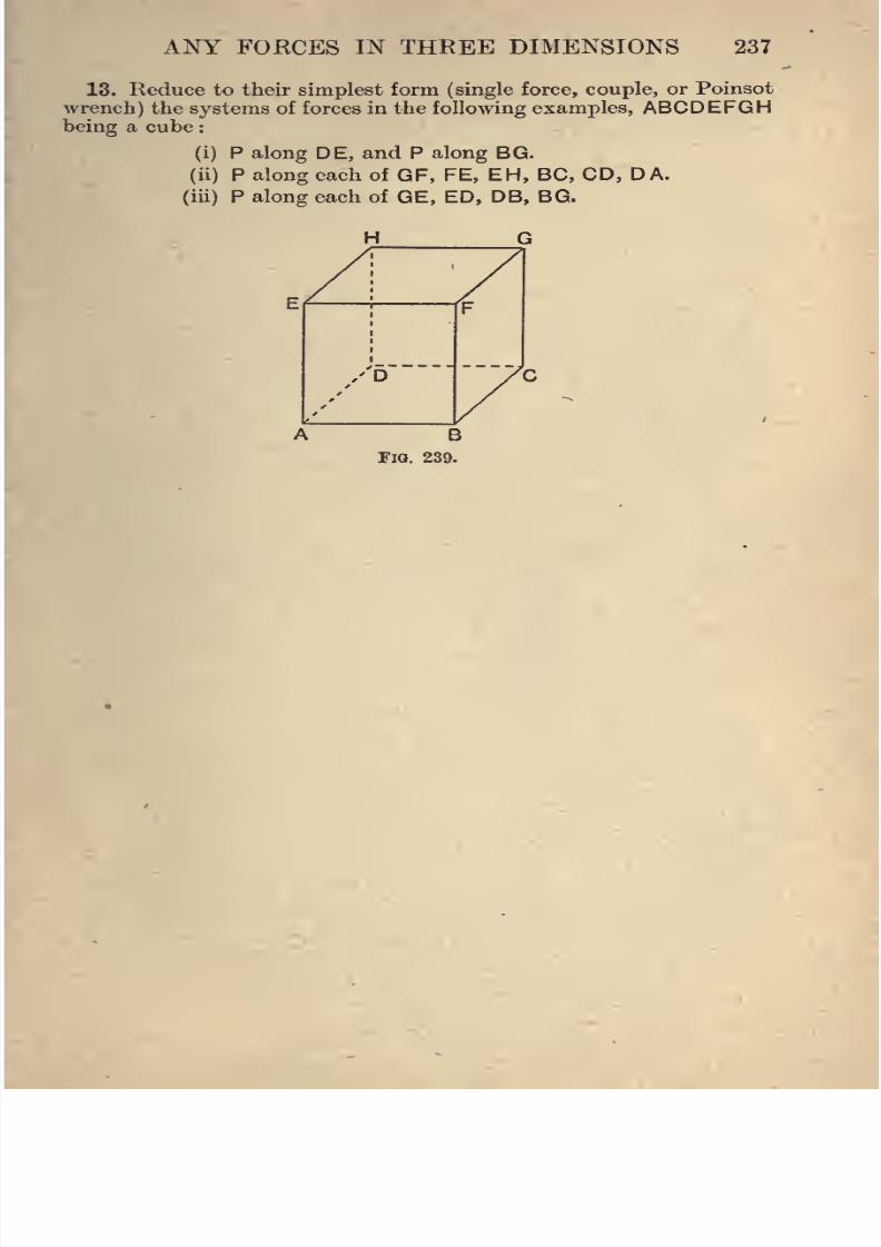
8/4/2019 Elementary Statics of 2 & Dimensions R.J.a. Barnard 1921
http://slidepdf.com/reader/full/elementary-statics-of-2-dimensions-rja-barnard-1921 249/272
ANY FORCES IN THEEE DIMENSIONS 237
13. Reduce to their simplest form (single force, couple, or Poinsot
wrench) the systems of forces in the following examples, ABCDEFGHbeing a cube
(i) P along DE, and P along BG.
(ii) P along each of GF, FE, EH, BC, CD, DA.
(iii) P along each of GE, ED, DB, BG.
H G
B
Fig. 239.
8/4/2019 Elementary Statics of 2 & Dimensions R.J.a. Barnard 1921
http://slidepdf.com/reader/full/elementary-statics-of-2-dimensions-rja-barnard-1921 250/272
CHAPTER XV.
VECTORS IN SPACE.
152. In my Elementary Dynamics are given some of the
elements of vector notation and vector algebra, including the
definition of the Scalar Product of two vectors. The results
given there are summarised here, and reference may be made
to that book for fuller explanations and proofs.
If A, B are two vectors, the scalar product of A and B is
defined as the scalar quantity AB cos 0, where A, B are the
magnitudes of A and B, and $ is the angle between them.
The scalar product is denoted -by A . B, and read A dot B.
We then have the following results in vector algebra :
A+B =B+A,
A-B=-(B-A),
A+B+C = (A+B)+C =A + (B+C), etc.,
m{A +B) = wiA + wB, if m is any scalar,
A.B = B.A,
A.(B +C)=A.B+A.C.
In dealing with questions relating to moments it is convenient
to have a notation for the vector which represents the moment
of a force about a point. We therefore introduce the Vector
Product of two vectors, and define it thus:
The Vector Product of two vectors A and B is a vector per-
pendicuhr to both, whose magnitude is equal to the product
AB sin 0,
238
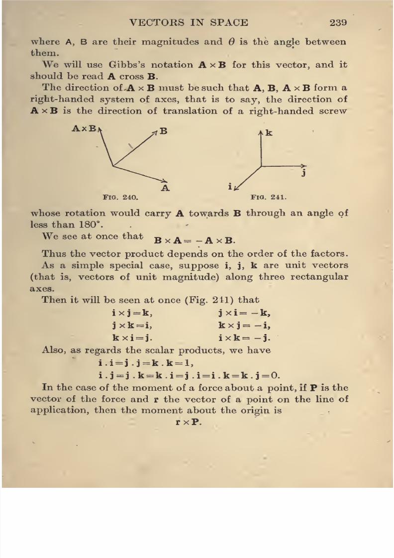
8/4/2019 Elementary Statics of 2 & Dimensions R.J.a. Barnard 1921
http://slidepdf.com/reader/full/elementary-statics-of-2-dimensions-rja-barnard-1921 251/272
VECTORS IN SPACE 239
where A, B are their magnitudes and 9 is the angle between
them.
We will use Gibbs's notation A x B for this vector, and it
should be read A cross B.
The direction of A x B must be such that A, B, A x B form a
right-handed system of axes, that is to say, the direction of
A X B is the direction of translation of a right-handed screw
AxBAk
Fio. 240. Fia. 241.
whose rotation would carry A towards B through an angle of
less than 180".
We see at once that BxA= -AxB
Thus the vector product depends on the order of the factors.
As a simple special case, suppose i, j, k are unit vectors
(that is, vectors of unit magnitude) along three rectangular
axes.
Then it will be seen at once (Fig. 211) that
ixj=k, jxi=-k,
jxk=i, kxj=-i,
kxi = j. ixk= -j.
Also, as regards the scalar products, we have
i.i=j . j=k.k = l,
i.j=^j.k = k.i = j.i = i.k = k.i=0.
In the case of the moment of a force about a point, if P is the
vector of the force and r the vector of a point on the line of
application, then the moment about the origin is
rxP.
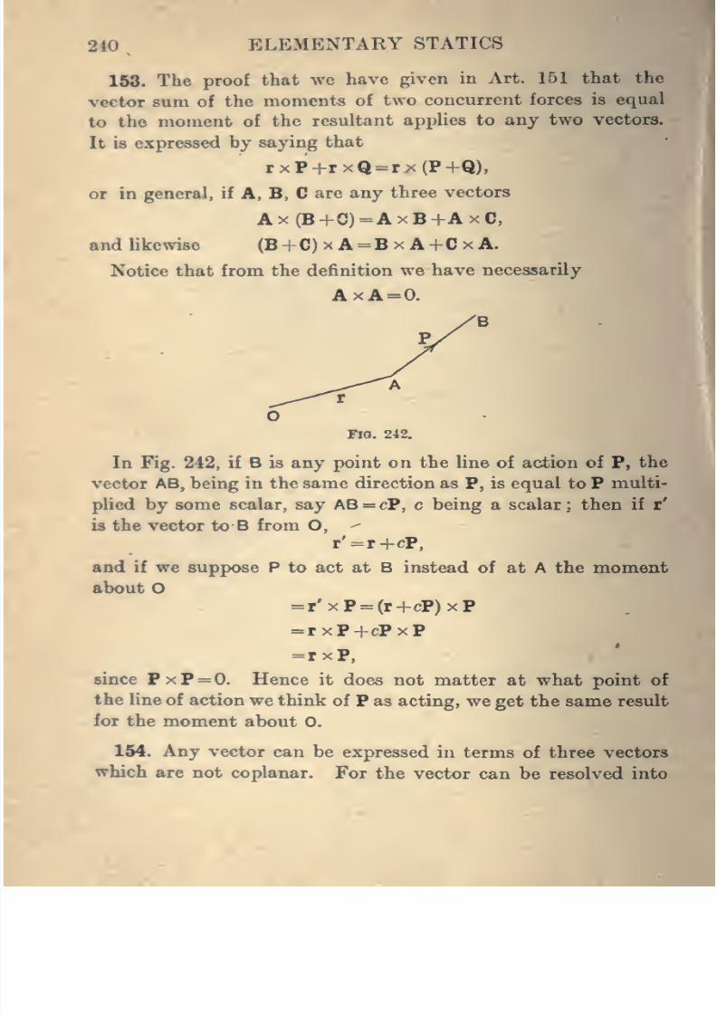
8/4/2019 Elementary Statics of 2 & Dimensions R.J.a. Barnard 1921
http://slidepdf.com/reader/full/elementary-statics-of-2-dimensions-rja-barnard-1921 252/272
240 ELEMENTARY STATICS
163. The proof that we have given in Art. 151 that the
vector sum of the moments of two concurrent forces is equal
to the moment of the resultant applies to any two vectors.
It is expressed by saying that
rxP+rxQ = rx(P+Q),
or in general, if A, B, C are any three vectors
Ax(B+C)=AxB+AxC,
and likewise (B+C) x A = B x A+Cx A.
Notice that from thedefinition
wehave necessarily
AxA=0.
'B
P.
Fig. 242.
In Fig. 242, if B is any point on the line of action of P, the
vector AB, being in the same direction as P, is equal to P multi-
plied by some scalar, say AB = cP, c being a scalar ;. then if r'
is the vector to B from O, ^
r'=r+cP,
and if we suppose P to act at B instead of at A the moment
about O=r'xP = (r+cP)xP
=rxP+cPxP
=rxP,
since PxP=0. Hence it does not matter at what point of
the line of action we think of P as acting, we get the same result
for the moment about 0.
154. Any vector can be expressed in terms of three vectors
which are not coplanar. For the vector can be resolved into
8/4/2019 Elementary Statics of 2 & Dimensions R.J.a. Barnard 1921
http://slidepdf.com/reader/full/elementary-statics-of-2-dimensions-rja-barnard-1921 253/272
VECTORS IN SPACE 241
components in any three directions, and hence if A, B, C are
three non-coplanar vectors, any other vector P can be resolved
along them, and we can write
P =aA+6B + cC, ^
where a, h, c are scalars or simply numbers.
In particular, if i, j. k are miit vectors at right angles a
vector P can be written
P^Pii + PaJ+Psk,
where P^, Po, Pg are the resolved parts of P in the three direc-
tions.
In the same way, any vector in the plane of A and B can be
written in the form
aA-f6B,
and conversely a vector of the form aA+6B is in the plane
containing A and B.
Examples. By writing
A = Aii-|-A2J+A3k
and similar notation for other vectors, prove that
(i) A.B = AiBi + A2B2 + A3B3.
(ii) A X B = (A2B3 - A3B2)i +(A3Bi - /K^B^)] + (A^Ba - A2Bi)k.
(iii) A X (B X C) = (A . C)B - (A . B)C.
All three of these results are extremely important, and thestudent should not proceed further before proving them. He
must also see clearly what is meant by each group of symbols.
155. In connection with three vectors there are several
important products.
Thus (A . B)C will be understood at once as the vector C
multiplied by a scalar, and is therefore a vector in the same
direction as C.
(A X B) . C is a scalar quantity in which first the vector A x B
is taken, and then the scalar product of it and the vector
C formed.
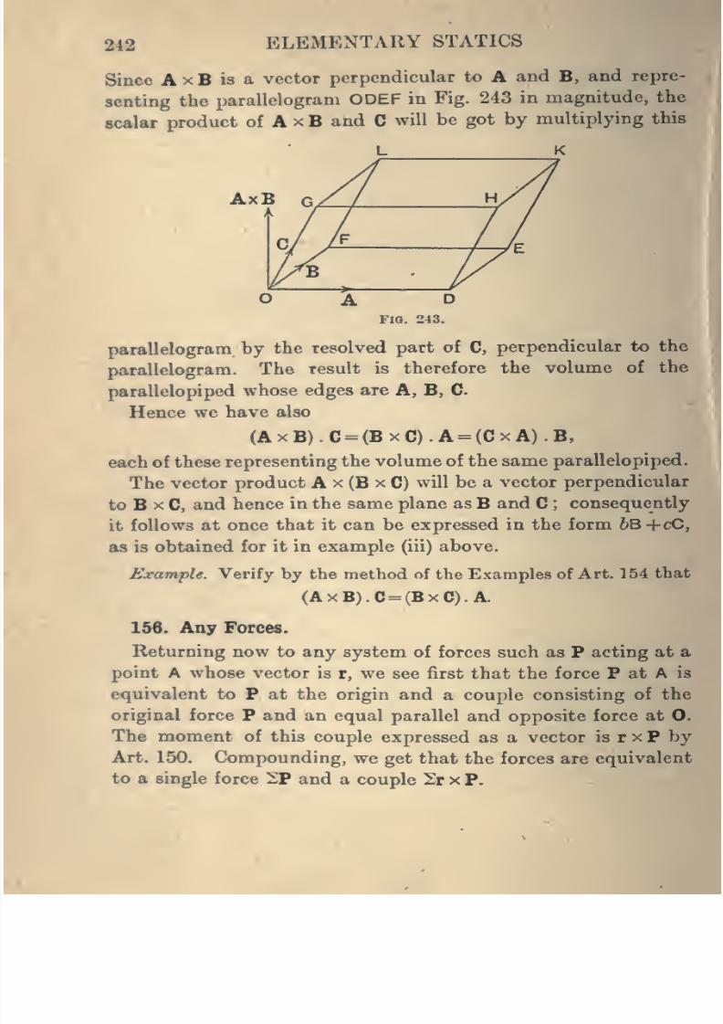
8/4/2019 Elementary Statics of 2 & Dimensions R.J.a. Barnard 1921
http://slidepdf.com/reader/full/elementary-statics-of-2-dimensions-rja-barnard-1921 254/272
242 ELEMENTARY STATICS
Since A x B is a vector perpendicular to A and B, and repre-
senting the parallelogram ODEF in Fig. 243 in magnitude, the
scalar product of A x B and C will be got by multiplying this
FlO. 243. miparallelogram by the resolved part of C, perpendicular to the
parallelogram. The result is therefore the volume of the
parallelopiped whose edges are A, B, CHence we have also
(AxB).C = (BxC).A = (CxA).B,
each of these representing the volume of the same parallelopiped.
The vector product A x (B x C) will be a vector perpendicular
to B X C, and hence in the same plane as B and C ; consequently
it follows at once that it can be expressed in the form hB+cO,
as is obtained for it in example (iii) above.
Example. Verify by the method of the Examples of Art. 154 that
(AxB).C= (BxC).A
156. Any Forces.
Returning now to any system of forces such as P acting at a
point A whose vector is r, we see first that the force P at A is
equivalent to P at the origin and a couple consisting of the
original force P and an equal parallel and opposite force at 0.
The moment of this couple expressed as a vector is r x P by
Art. 150, Compounding, we get that the forces are equivalent
to a single force 2P and a couple 2r x P.
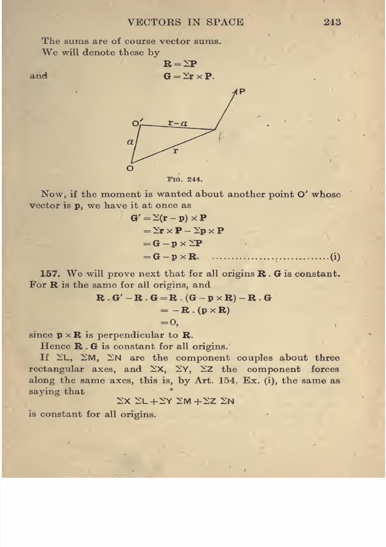
8/4/2019 Elementary Statics of 2 & Dimensions R.J.a. Barnard 1921
http://slidepdf.com/reader/full/elementary-statics-of-2-dimensions-rja-barnard-1921 255/272
VECTORS IN SPACE 243
The suras are of course vector sums.
We will denote these by
R = 2P
and G = 2rxP.
O
Fig. 244.
Now, if the moment is wanted about another point O' whose
vector is p, we have it at once as
G'=2(r-p)><P
=2rxP-2pxP
=G-px2P
= G-pxR (i)
157. We will prove next that for all origins B . G is constant.
For R is the same for all origins, and
R.G'-R.G =R.(G-pxR)-R.G= - R . (p X R)
=0,
since p X R is perpendicular to R.
Hence R . G is constant for all origins.
If 2L, 2M, 2N are the component couples about three
rectangular axes, and 2X, 2Y, 2Z the component forces
along the same axes, this is, by Art. 154. Ex. (i), the same as
saying that*
2X2L+2Y2IVI+2Z 2N
is constant for all origins.
8/4/2019 Elementary Statics of 2 & Dimensions R.J.a. Barnard 1921
http://slidepdf.com/reader/full/elementary-statics-of-2-dimensions-rja-barnard-1921 256/272
%
2U ELEMENTARY STATICS
If in (i) of Art. 156 p is parallel to R,
pxR = 0;
•
G' = G,
or the resultant moment is the same at all points on a line
parallel to the resultant force.
158. Next let us try to find a point at which the vector of the
resultant moment is parallel to the resultant force. To do ^ I
this draw a plane through O perpendicular to R ; then if p is
the vector to a point A on this plane, and if the moment at A
is parallel to R, then
G - p X R is parallel to R,
or G - p X R = mR,
where m is some scalar.
Take the vector product of each side by R
.*. RxG-Rx(pxR)=RxmR;
also by Art. 154, Ex. (iii),
R X (p X R) = (R . R)p - (R . p)R
= R2p - (R . p)R ;
now R . p = 0, because R is perpendicular to p
.*. Rx(pxR)-R2p;
also RxmR =m(RxR)=0;
.*. RxG-R2p = 0;
.*. p = ^RxG,
giving one point on the plane, since we have one definite value
for p. Hence there is one line such that at all points of it the
vector of the resultant moment coincides with the direction of
the resultant force.
This line is called Poinsot's Central Axis.
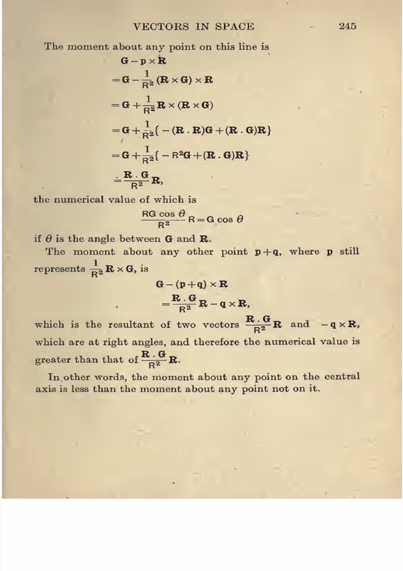
8/4/2019 Elementary Statics of 2 & Dimensions R.J.a. Barnard 1921
http://slidepdf.com/reader/full/elementary-statics-of-2-dimensions-rja-barnard-1921 257/272
VECTORS IN SPACE - 245
The moment about any point on this line is
G-pxk
=G--2(RxG)xR
= G+^Rx(RxG)
= G+ ^\{-(R.R)G+(R.G)R}
= G +^{-R2G+ (R.G)R}
--R2-R,
the numerical value of which is
RG cos „ „ a—-^— R = GcosOR''
if is the angle between G and R.
The moment about any other point p+q, where p still
represents ^ R x G, is
G-(p+q)xR
R.G,
R2R - q X R,
R Gwhich is the resultant of two vectors -^ R and -qxR,
which are at right angles, and therefore the numerical value is
R Ggreater than that of A R.
In other words, the moment about any point on the central
axis is less than the moment about any point not onit.
8/4/2019 Elementary Statics of 2 & Dimensions R.J.a. Barnard 1921
http://slidepdf.com/reader/full/elementary-statics-of-2-dimensions-rja-barnard-1921 258/272
APPENDIX.
NOTE ON THE HISTORY OF STATICS. xinr:
The first attempts at a discussion of Statical Principles ate
due to Archimedes (287-212 B.C.), who dealt with the principle
of the lever, as it was long called ; in other words, with moments 5
of parallel forces. He was thus led to the consideration of
centres of mass, which he investigated to a remarkable extent,
finding, for example, the centre of mass of a paraboloid.
Pappus, who gave the theorems of Art. 116, lived in the third
century a.d.
Modern Statics may be said to begin with Stevinus (1548-
1620), who based his work on the triangle of forces, but the
systematic treatment in the modern way, developed from the
parallelogram of forces, maybe ascribed to Varignon (1644-1722).
The principle of Virtual Work (then called Victual Velocities)
is due to Lagrange (1736-1813), perhaps the greatest mathe-
matician since Newton. Most of Lagrange's work in mechanics
is based on this principle.
The theory of couples in general and the reduction of a system
of forces in space to a wrench (Art. 141) is due to Poinsot
(1777-1859).
The theory of vectors originated with Hamilton (1805-1865)
and Grassmann (1809-1877), and has been developed and
simplified by many workers of the nineteenth century.
The general methods of graphical statics, including the
funicular polygon, are due to Culmann (1821-1881).
246
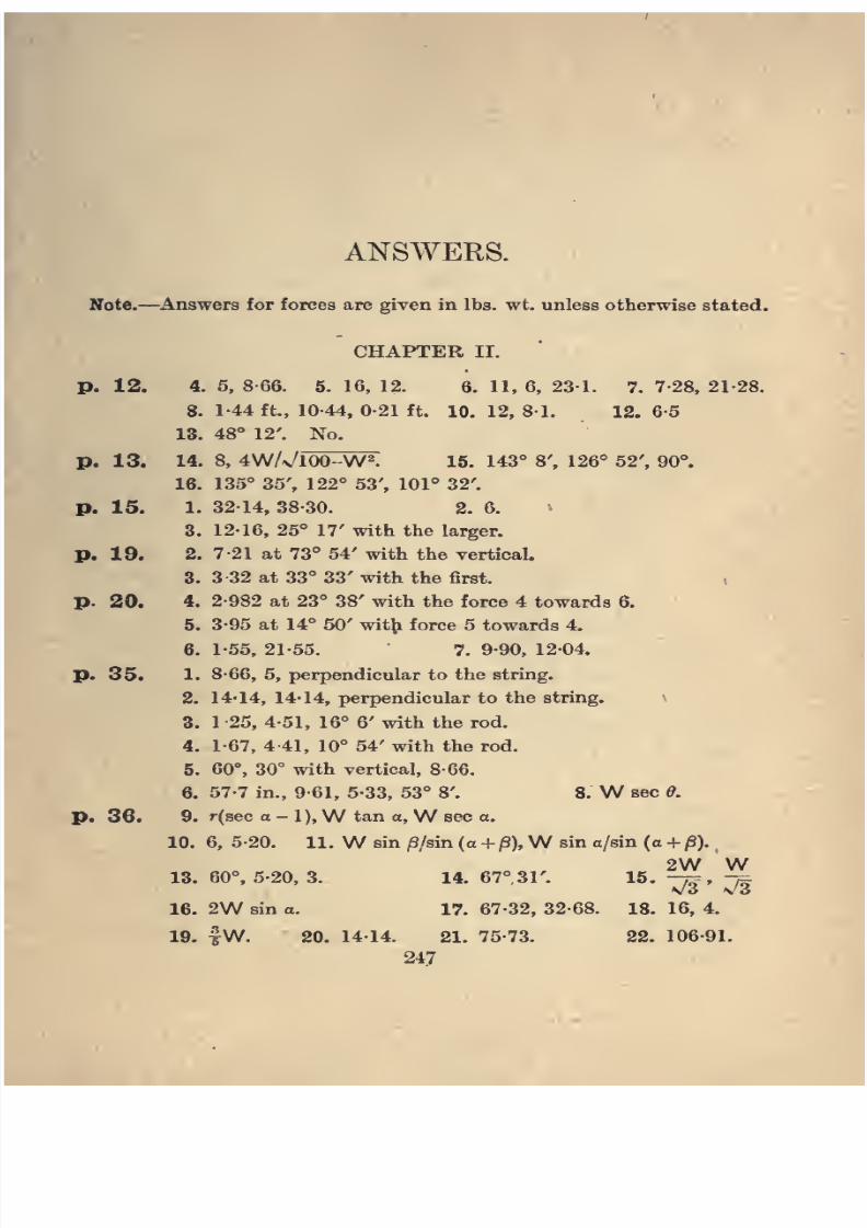
8/4/2019 Elementary Statics of 2 & Dimensions R.J.a. Barnard 1921
http://slidepdf.com/reader/full/elementary-statics-of-2-dimensions-rja-barnard-1921 259/272
ANSWERS.
Note.—Answers for forces are given in lbs. wt. unless otherwise stated.
CHAPTER II.
p. 12. 4. 5, 8-66. 5. 16, 12. 6. 11, 6, 231. 7. 7-28, 21-28.
8. 1-44 ft., 10-44, 0-21 ft. 10. 12, 81. 12. 6-5
13. 48° 12'. No.
p. 13. 14. 8, 4W/V100-W2. 15. 143° 8', 126° 62', 90°.
16. 135° 35', 122° 53', 101° 32'.
p. 15. 1. 32-14, 38-30. 2. 6.
3. 12-16, 25° 17' with the larger.
p. 19. 2. 7-21 at 73° 54' with the vertical.
3. 3 32 at 33° 33' with the first. ,
p. 20. 4. 2-982 at 23° 38' with the force 4 towards 6.
5. 3-95 at 14° 50' wit]^ force 5 towards 4.
6. 1-55, 21-55. 7. 9-90, 1204.
p. 35. 1. 8-66, 5, perpendicular to the string.
2. 14-14, 14-14, perpendicular to the string. \
3. 1 -25, 4-51, 16° 6' with the rod.
4. 1-67, 4 41, 10° 54' with the rod.
6. 60°, 30' with vertical, 8-66.
6. 57-7 in., 9-61, 5-33, 53° 8'. 8. W sec 0.
p. 36. 9. r(sec a - 1),W tan a,W sec a.
10. 6, 5-20. 11. W sin /3/sin (a + ^3),W sin a/sin (a + p).
2W W13. 60°, 5-20, 3. 14. 67° 31'. ^^-
T/g' 7/5
16. 2W sin a. 17. 67-32, 32-68. 18. 16, 4.
19. fW. 20. 14- 14. 21. 75-73. 22. 106-91.
247
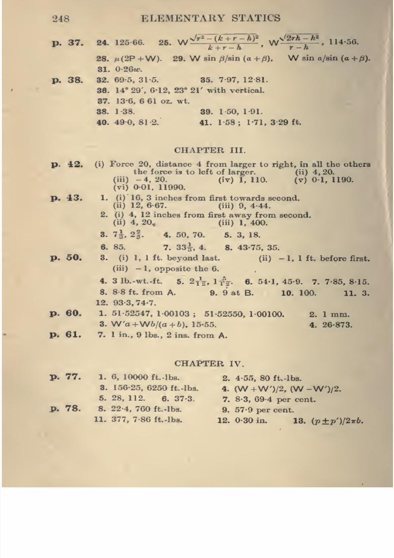
8/4/2019 Elementary Statics of 2 & Dimensions R.J.a. Barnard 1921
http://slidepdf.com/reader/full/elementary-statics-of-2-dimensions-rja-barnard-1921 260/272
248 ELEMENTARY STATICS
p. 37. 24. 125-66. 25. ^^^r*-(k + r-h)> W^^^^. lU-56.
28. m(2P + W). 29. W Bin /S/sin (o + /3), W sin a/sin (a +/3).
81. 0-26w.
p. 38. 32. 69 5, 31-5. 86. 7 97, 12 81.
86. 14° 29'. 612, 23° 21' with vertical.
87. 13-6, 6 61 oz. wt.
88. 1 38. 89. 150, 191.
40. 49 0, 81 -2. 41. 158 ; I 71, 329 ft.
CHAPTER III.
p. 42. (i) Force 20, distance 4 from larger to right, in all the others
the force is to left of larger. (ii) 4, 20.
(iii) -4, 20. (iv) 1, 110. (v) 01, 1190.
(vi) 001, 11990.
p. 43. 1. (i) 16, 3 inches from first towards second,
(u) 12, 6-67. (iii) 9, 4-44.
2. (i) 4, 12 inches from first away from second,
(ii) 4, 20, (iii) 1, 400.
8. 7j, 2§. 4. 50, 70. 5. 3, 18.
6. 85. 7. 33^, 4. 8. 43-75, 35.
p. 50. 3. (i) 1, 1 ft. beyond last. (ii) -1, 1 ft. before first,
(iii) - 1, opposite the 6.
4. 3 lb.-wt.-ft. 5. 2i^^, IfV. 6. 54-1, 45-9. 7. 7-85, 8-15.
8. 8-8 ft. from A. 9. 9 at B. 10. 100. 11. 3.
12. 93-3,74-7.
p. 60. 1. 51-52547, 1-00103 ; 51-52550, 1-00100. 2. 1 mm.
3. W'o+W6/(a + 6), 15-55. 4. 26-873.
p. 61. 7. 1 in., 9 lbs., 2 ins. from A.
CHAPTER IV.
p. 77. 1. 6, 10000 ft. -lbs. 2. 4-55, 80 ft. -lbs.
8. 156-25, 6250 ft.-lbs. 4. (W +W')/2, (W -W')/2.
5. 28, 112. 6. 37-3. 7. 8-3, 69-4 per cent.
p. 78. 8. 22-4, 760 ft. -lbs. 9. 57-9 per cent.
11. 377, 7-86 ft. -lbs. 12. 0-30 in, IZ. {p±p'y2irb.
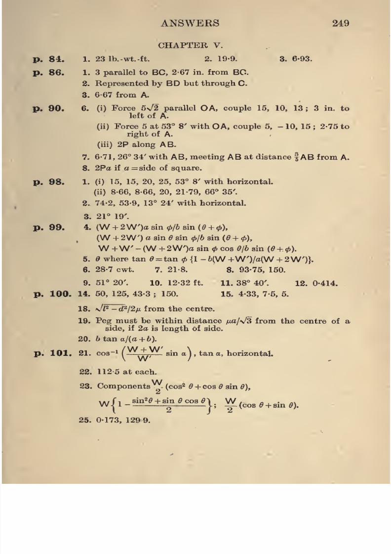
8/4/2019 Elementary Statics of 2 & Dimensions R.J.a. Barnard 1921
http://slidepdf.com/reader/full/elementary-statics-of-2-dimensions-rja-barnard-1921 261/272
ANSWERS 249
CHAPTER V.
p. 84. 1. 23 Ib.-wt.-ft. 2. 19-9. 3. 6-93.
p. 86. 1. 3 parallel to BC,2-67
in. from BC.2. Represented by BD but through C.
3. 6-67 from A.
p. 90. 6. (i) Force 5n/2 parallel OA, couple 15, 10, 13 ; 3 in. to
left of A.
(ii) Force 5 at 53° 8' with OA, couple 5, - 10, 15 ; 2-75 to
right of A.
(iii) 2P along AB.
7. 6-71, 26° 34' with AB, meeting AB at distance fAB from A.
8. 2Pa if a = side of square.
p. 98. 1. (i) 15, 15, 20, 25, 53° 8' with horizontal,
(ii) 8-66, 8-66, 20, 21-79, 66° 35'.
2. 74-2, 53-9, 13° 24' with horizontal.
3. 21° 19'.
p. 99. 4. (W + 2W')a sin 0/6 sin {9 + <p),
(W + 2W') a sin e sin 0/6 sin (^ + 0),
W +W - (W + 2W')a sin<f>cos O/b sin {6 + 4>).
5. where tan ^ = tan<f> {1 -6(W+W')/a(W + 2W')}.
6. 28-7 cwt. 7. 21-8. 8. 93-75, 150.
9. 51° 20'. 10. 12-32 ft. 11. 38° 40'. 12. 0-414.
p. 100. 14. 50, 125, 43-3; 150. 15. 4-33, 7-5, 5.
18. \/l^ - d^/2fi from the centre.
19. Peg must be within distance fjca/s/S from the centre of a
side, if 2a is length of side.
20. 6 tana/(a + 6).
p. 101. 21. cos-i( ^, sin a\ , tan a, horizontal.
22. 112-5 at each.
23. Components^ (cos^ ^ + cos 5 sin 6),
Wf, sin^^ + sin ^cos^) W, a . a\O ^ v ; -^ (cos 6 + sm 6).
25. 0173, 129 9.
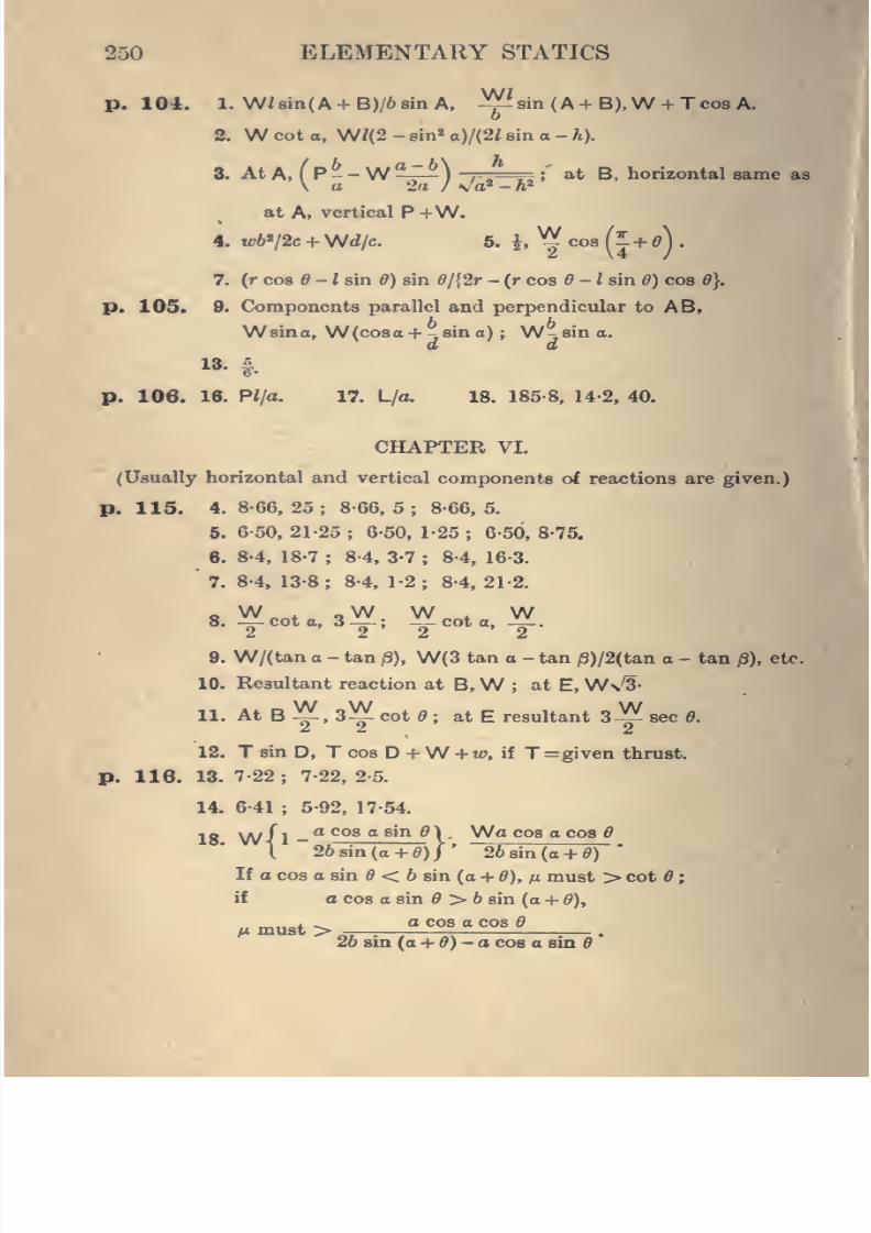
8/4/2019 Elementary Statics of 2 & Dimensions R.J.a. Barnard 1921
http://slidepdf.com/reader/full/elementary-statics-of-2-dimensions-rja-barnard-1921 262/272
250 ELEMENTARY STATICS
p. 104. 1. W/8in(A + B)/68inA, -^isin (A + B),W + Tco8 A.
2. W cot o, WI(2 - 8in« o)/(2i sin a - h).
8. At A, ( P - -W ^-^) /
. rs > at B, horizontal same as
at A, vertical P +W.
4. tt*V2c + Wd/c. 6. h ^ cos(J + ») •
7. (r cos ^ - / sin 6) sin ^/{2r - (r cos 5 - Z sin ^) cos 6}.
p. 105. 9. Components parallel and perpendicular to AB,
Wsina, W(coaa+ jSino) ;
W^sino.d d
p. 106. 16. Pl/a. 17. L/a. 18. 185-8, 14-2, 40.
CHAPTER VI.
(Usually horizontal and vertical components of reactions are given.)
p. 115. 4. 8-66, 25 ; 8-66, 5 ; 8-66, 5.
6. 6 50, 21-25 ; 6-50, 1-25; 6-50, 8-75.
6. 8-4, 18-7; 8-4, 3-7 ; 8-4, 16-3.
7. 8-4, 13-8; 8-4, 1-2
; 8-4, 21-2.
9. W/(tan a - tan /3), W(3 tan a - tan /3)/2(tan o - tan jS), etc.
10. Resultant reaction at B,W ; at E, W\^-
11. At B ^ , 3^ cot « ; at E resultant 3^ sec 6.
12. T sin D, T cos D +W + «?, if T =given thrust.
p. lie. 13. 7-22; 7-22, 2-5.
14. 6-41 ; 5-92, 17-54.
Wa cos a cos ff
%
18 \A//i _ aco8 g sin g )
.
t 26sin(a + »)J'
26 sin (a -f 0)
If o cos o sin ^ < 6 sin (a + 6), n must > cot 6 ;
if a cos o sin > 6 sin (a + d),
a cos a cos 6M must >
26 sin (a + 0) - a cos a sin *
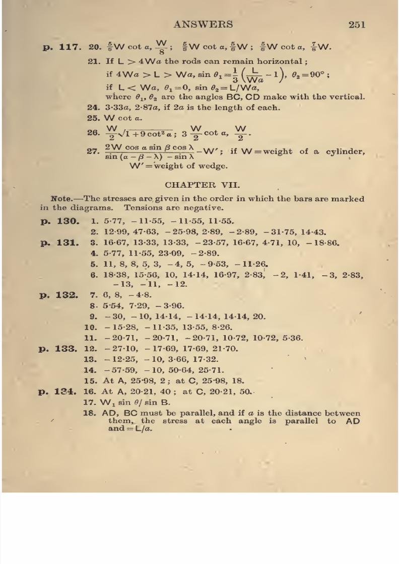
8/4/2019 Elementary Statics of 2 & Dimensions R.J.a. Barnard 1921
http://slidepdf.com/reader/full/elementary-statics-of-2-dimensions-rja-barnard-1921 263/272
ANSWEKS 251
p. 117. 20. fWcota, ^; |Wcoto,tW; |W cot a, |W.8
21. If L > 4Wa the rods can remain horizontal
if
4Wa>L>Wa, sin ^1 =^(^-0, ^2 = 90°;3 \Wa /
if L < Wa, $1=0, sin e^^L/Wa,
where d^, 6^ are the angles BC, CD make with the vertical.
24. 3-33a, 2-87a, if 2a is the length of each.
25. W cot a.
26. ^Vl+Qcot^a; 3^ cot a, ^.
„- 2W cos a sin 8 cos X ..,, -f ../ • i.i. i i- j
27.-;
—;;
^—-.
— "W;
if
W = wcight of a cylmder,sm{a-(8-X) -smX ^ •'.
W' = weight of wedge.
CHAPTER VII.
Note.—The stresses are given in the order in which the bars are marked
in the diagrams. Tensions are negative.
p. 130. 1. 5-77, -11-55, -11-55, 11-55.
2. 12-99,47-63, -25-98,2-89, -2-89, -31-75,14-43.
p. 131. 3. 16-67, 13-33, 13-33, -23-57, 16-67, 4-71, 10, -18-86.
4. 5-77, 11-55, 23-09, -2-89.
5. 11,8,8,5,3, -4,5, -9-53, -11-26.
6. 18-38, 15-56, 10, 14-14, 16-97, 2-83, -2, 1-41, -3, 2-83,
-13, -11, -12.
p. 132. 7. 6,8, -4-8.
8. 5-54, 7-29, -3-96.
9. -30,-10,14-14,-14-14,14-14,20.
10. -15-28, -11-35, 13-55, 8-26.
11. -20-71, -20-71, -20-71,10-72,10-72,5-36.
p. 133. 12. -27-10, -17-69,17-69,21-70.
18. -12-25, -10,3-66, 17-32.
14. -57-59, -10,50-64,25-71.
15. At A, 25-98, 2; at C, 25-98, 18,
p. 134. 16. At A, 20-21, 40 ; at C, 20-21, 5a
17. Wi sin (9/ sin B.
18. AD, BC must be parallel, and if a is the distance between
them, the stress at each angle is parallel to ADand = L/a.
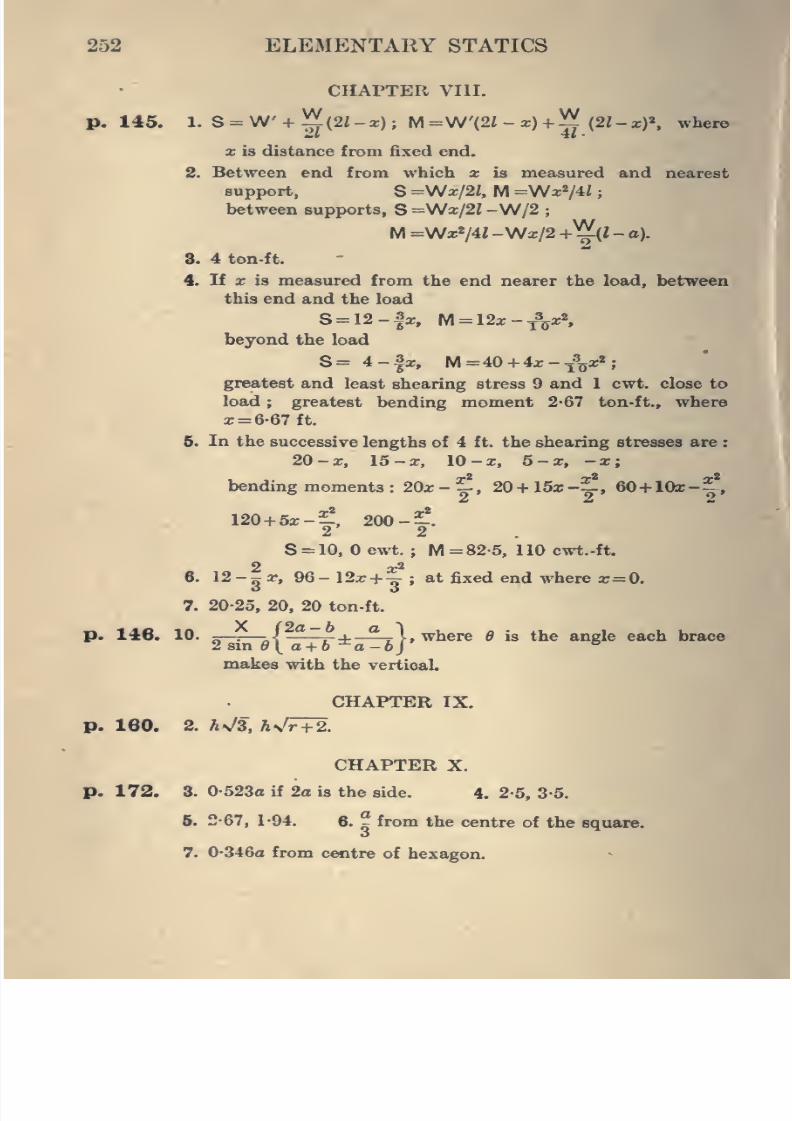
8/4/2019 Elementary Statics of 2 & Dimensions R.J.a. Barnard 1921
http://slidepdf.com/reader/full/elementary-statics-of-2-dimensions-rja-barnard-1921 264/272
252 ELEMENTARY STATICS
CHAPTER VIII.
p. 145. 1. S =W + ^ (21 -x); M =\N'{21 -x) +~ (21- xf, where
X is distance from fixed end.
2. Between end from which x is measured and nearest
support, S =Wx/2i, M =\Nx^/U ;
between supports, S =Wx/2i -W/2 ;
M =Wx*/4i -Wa:/2 + ^{1 - a).
8. 4 ton-ft.
4. If X is measured from the end nearer the load, between
this end and the load
S = 12-|x, M = 12x-^xS JBibeyond the load "^^B I
S= 4-|x, M=40 + 4x-^V*''
greatest and least shearing stress 9 and 1 cwt. close to
load; greatest bending moment 2-67 ton-ft., where
x = 6-67 ft.
5. In the successive lengths of 4 ft. the shearing stresses are
20 - X, 15 - X, 10 - X, 6 - X, - X
bending moments : 20x - ^ , 20 + 15x-^ , 60+ lOx -f
X2
2'
120-f-5x--, 200 -; .
2 2
S = 10, cwt. ; M =82-5, 110 cwt.-ft.
2 x^6. I2-3X, 96-12x + ~; at fixed end where x=0.
7. 20-25, 20, 20 ton-ft.
p. 146. 10. jr-T -\^f- j-—^ i, where d is the angle each brace
makes with the vertical.
CHAPTER IX.
p. 160. 2. A>/3, hxJr+2.
CHAPTER X.
p. 172. 3. 0-523a if 2a is the side. 4. 2-5, 3-5.
5. 2-67, 1-94. 6. ^ from the centre of the square.
7. 0-346a from centre of hexagon.
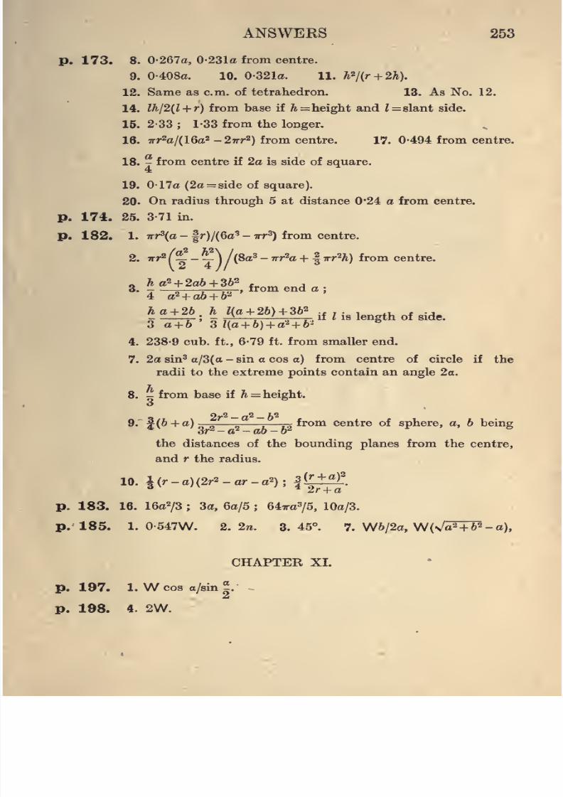
8/4/2019 Elementary Statics of 2 & Dimensions R.J.a. Barnard 1921
http://slidepdf.com/reader/full/elementary-statics-of-2-dimensions-rja-barnard-1921 265/272
ANSWEES 253
p. 173. 8. 0-267a, 0-231a from centre.
9. 0-408a. 10. 0-321a. 11. A2/(r + 2A).
12. Same as cm. of tetrahedron. 13. As No. 12.
14. lh/2{l + r) from base if ^=height and Z = slant side.
15. 2-33 ; 1-33 from the longer.
18. wr^a/{16a^-2irr'^) from centre. 17. 0-494 from centre.
18. y from centre if 2a is side of square.4
19. 0-17a (2a = side of square).
20. On radius through 5 at distance 0*24 a from centre.
p. 174. 25. 3-71 in.
p. 182. 1. 7rr3(a - |r)/(6a^ - TTT^) from centre.
2. 7rr2f^-j) /(8a3 - Trr^a + |irr'^h) from centre.
3. ^^i+2^^+#^,fromenda;4 a^ + ab + l)^
3 a + b 3 l(a+ b) + a^ + b'
^
4. 238-9 cub. ft., 6-79 ft. from smaller end.
7. 2a sin^ a/3(a-sin a cos a) from centre of circle if the
radii to the extreme points contain an angle 2o.
8. - from base if ^ = height.
_ 2r^ — a^ — b^9. f{b + a)—^ —^ from centre of sphere, a, b being
the distances of the bounding planes from the centre,
and r the radius.
10. 4 (r - o) {2r2 - ar - a2); I (!L±fI^.
p. 183. 16. 16a2/3 ; 3a, 6a/5 ; 647ra3/5, lOa/3.
p. 185. 1. 0-547W. 2. 2n. 3.45°. 7. W6/2a, W(\/aM^-o),
CHAPTER XL
p. 197. 1. W cos o/sin ~.
p. 198. 4. 2W.
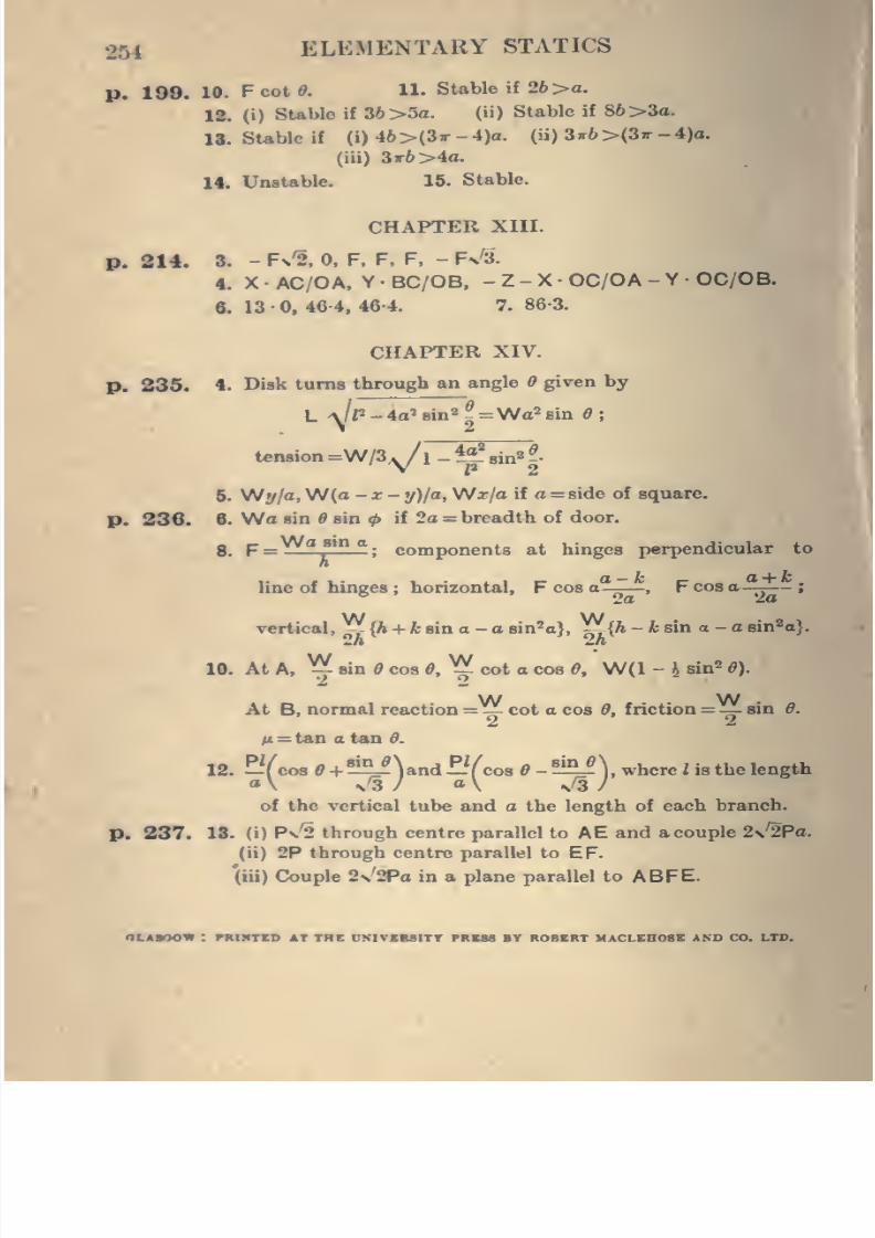
8/4/2019 Elementary Statics of 2 & Dimensions R.J.a. Barnard 1921
http://slidepdf.com/reader/full/elementary-statics-of-2-dimensions-rja-barnard-1921 266/272
^54 ELEMENTARY STATICS
p. 199. 10. Fcottf. 11. Stable if 26 >o.
12. (i) SUblo if 36>5a. (ii) Stable if 86>3a.
18. SUble if (i) 46 >(3t - 4)o. (ii) 3»6 >(5k - 4)o.
(iii) 3ir6>4a.
14. Unstable. 16. SUble.
CHAPTER XIII.
p. 214. 3. - f\% 0, F, F, F, - Fn'S.
4. X • AC/OA, Y • BC/OB, - Z - X • OC/OA - Y • OC/OB.
8. 13 • 0, 46 4, 46-4. 7. 86-3.
CHAPTER XIV.
p. 236. 4. Disk turns through an angle given by
tension =W/3^1 -i^%in2|.
6. Wy/o, W(o -X- y)la, W^xfa if a= side of square.
p. 236. 6. Wo sin 6 sin ^ if 2a = breadth of door.
8.p-Wasin a.
components at hinges perpendicular to
line of hinges ; horizontal, F cos a~
, F cos o.—-— ;
vertical,J[*
{A + 1 sin a - o sin-a}, \fAh - fc sin a - o sin^o}.
10. At A,
^sin e cos 0,
^cot a cos 6, W(l - t sin^ 6).
W W •
At B, normal reaction = — cot a cos d, friction = —- sm 6.
2 2
M = tan a tan 0.
12. -fees e +?^Vnd—Ycos 6 - !iBiV where I is the length
of the vertical tube and a the length of each branch.
p. 237. 18. (i) Ps'2 through centre parallel to AE and a couple 2\^Pa.
(ii) 2P through centre parallel to EF.
(iii) Couple 2v'2Pa in a plane parallel to ABFE.
oL«aoow : raiimcD at trk univbbsitt pbus bt robkrt maclkbosb and go. ltd.
8/4/2019 Elementary Statics of 2 & Dimensions R.J.a. Barnard 1921
http://slidepdf.com/reader/full/elementary-statics-of-2-dimensions-rja-barnard-1921 267/272
BY THE SAME AUTHOR.
ELEMENTARY DYNAMICS OF THE PARTICLE AND RIGID
BODY. Crown 8vo. 6s.
CONTENTS.
Part I. The Particle. Chap. I. Position ; Velocity
Acceleration. II. Motion in a Straight Line ; Kinematics.
III. Force and Mass ; Motion in a Straight Line. IV. Forces
in Two Dimensions. V. Vector Methods. VI. Simple Har-
monic Motion. VII. Motion in a Plane Curve. VIII. The
Simple Pendulum. IX. Projectiles. X. Collision.
Part II. The Rigid Body. Chap. I. Rigid Kinematics.
II. Rotation about a Fixed Axis ; Moments of Inertia. III.
Rotation about a Fixed Axis ; Examples. IV. Motion of a
Rigid Body in a Plane. Appendix—History of Dynamics.
Answers.
OTHER WORKS ON MIXED MATHEMATICS
A TREATISE ON DYNAMICS. By Prof. Andrew Gray, F.R.S.,
and James Gordon Gray, D.Sc, Crown 8vo. ISs. net.
HYDROSTATICS FOR BEGINNERS. By F. W. Sanderson,
M.A. Globe 8vo. 3s.
TREATISE ON HYDROSTATICS. By Sir A. G. Greenhill,F.R.S. Crown Bvo. 8s. 6d.
LESSONS IN APPLIED MECHANICS. By Prof. J. H. Cotterill
and J. H. Slade. Fcap. 8vo. Vol. I. containing Parts I. and
III. 3s. 6d. Vol. IL containing Part II. 3s. 6d. Complete, 6s. 6d.
APPLIED MECHANICS FOR BEGINNERS. By J. Duncan,
Wh.Ex. Globe 8vo. 3s. 6d.
STEAM AND OTHER ENGINES. By J. Duncan, Wh.Ex.
Globe 8vo. 6s.
LONDON: MACMILLAN AND CO., LTD.
8/4/2019 Elementary Statics of 2 & Dimensions R.J.a. Barnard 1921
http://slidepdf.com/reader/full/elementary-statics-of-2-dimensions-rja-barnard-1921 268/272
WORKS ON PHYSICS.
A TEXT-BOOK OF PHYSICS FOR THE USE OF StUDENTS
OF SCIENCE AND ENGINEERING. By J. Duncan, Wh.Ex.,
M.I.Mech.E., and S. G. Starling, B.Sc, A.R.C.Sc. Illus-
trated. Extra crown 8vo. IBs. Also in Parts : Dynamics,
6e. ; Heat, Light, and Sound, 7s. 6d. ; Magnetism and Elec-
tricity, 5s. ; Heat, 4s. 6d. ; Light and Sound, 4s. 6d.
A TEXT-BOOK OF PRACTICAL PHYSICS. By H. S. Allen,
M.A., D.Sc, and H. Moore, A.R.C.Sc., B.Sc. Extra crown 8vo.
10s. 6d. net. Also Vol. I. (Part I. Properties of Matter). 4s.
net. Vol. II. (Parts II., III., and IV. Sound, Light, and Heat).
48. net. Vol. III. (Parts V. and VI. Magnetism and Electricity).
4b. net. Part I. Properties of Matter, and Part IV. Heat.
6s. net.
GENERAL PHYSICS FOR STUDENTS. A Text-Book on the
Fundamental Properties of Matter. By E. Edser, A.R.C.Sc.
Globe 8vo. Ss. 6d.
HEAT FOR ADVANCED STUDENTS. By E. Edser, A.R.C.Sc,
Globe Svo. 58. 6d.
LIGHT FOR STUDENTS. ByE.
Edser,A.R.C.Sc. Globe Svo.
7s.
TREATISE ON PRACTICAL LIGHT. By R. S. Clay, D.Sc.
Extra crown Svo. 128. 6d. net.
A TEXT-BOOK ON SOUND. By Prof. Edwin H. Barton,
.
D.Sc, F.R.S. Second Impression, revised. Extra crown Svo.
12s. 6d. net.
LONDON : MACMI1J.AN AND CO., LTD.
8/4/2019 Elementary Statics of 2 & Dimensions R.J.a. Barnard 1921
http://slidepdf.com/reader/full/elementary-statics-of-2-dimensions-rja-barnard-1921 269/272
8/4/2019 Elementary Statics of 2 & Dimensions R.J.a. Barnard 1921
http://slidepdf.com/reader/full/elementary-statics-of-2-dimensions-rja-barnard-1921 270/272
8/4/2019 Elementary Statics of 2 & Dimensions R.J.a. Barnard 1921
http://slidepdf.com/reader/full/elementary-statics-of-2-dimensions-rja-barnard-1921 271/272
PhysicsMechB
r^J—;—ni
o
C
s
University of Toronto
library
40
«
Si-*» DO NO'l' /f
REMOVE / ^
/'
CO
cvi
o» •
r-i
•->
O
O
THE J J
CARD -i f1
J^ 2'
FROM ^ ^•
CO
THIS \'
Author
Barnard a
B
r-i
u•**
H
POCKET \,
Acme Library Card PocketUnder Pat. "Ref. Index FUe"
Made by LIBRARY BUREAU
8/4/2019 Elementary Statics of 2 & Dimensions R.J.a. Barnard 1921
http://slidepdf.com/reader/full/elementary-statics-of-2-dimensions-rja-barnard-1921 272/272
nun»<mMtf/hMm\i/titmviMi.
• !>V^*4^>T ««»>p»«^««*>« ^.