elementary dynamo design.pdf
300
-
Upload
mukesh-kumar -
Category
Documents
-
view
65 -
download
6
Transcript of elementary dynamo design.pdf
LIBRARY
UNIVERSITY OF CALIFORNIA.
Class

ELEMENTARY DYNAMO DESIGN
ELEMENTARY
DYNAMO DESIGNWITH NUMERICAL EXAMPLES
BY
W. BENISON HIRD, B.A., M.I.E.E.t
Lecturer on Dynamo Design at the Glasgow and
West of Scotland Technical College
WITH 128 DIAGRAMS
CASSELL AND COMPANY, LIMITED
LONDON, PARIS, NEW YORK TORONTO AND MELBOURNE
1908
1VH3M30
ALL RIGHTS RESERVED
PREFACE
THE aim of this volume is to explain, by means of numerical
examples, the methods and calculations necessary for the
design of dynamo-electric machinery. Controversial points
as to the nicety of design are avoided as belonging to a
more advanced study of the subject than is here intended,
but the general effect of different modifications are noted
as occasion arises.
Whilst no endeavour has been made to treat of the
theory of electricity and magnetism, introductory chapters
deal with points that are most intimately connected with
dynamo design in such a way as will, it is hoped, enable
those who approach the subject from the practical side,
and without any deep theoretical training, intelligently to
follow the reasoning in the succeeding chapters.
A system of mixed units is used throughout the book :
the dimensions of all parts of the machines are given in
inches, whilst all the magnetic calculations are worked
out in centimeters. It is necessary that the finished results
should be put into the shops in feet and inches, but all
scientific works and original papers dealing with magnetism
invariably base their calculations on the centimeter as the
unit of length. If a design be worked out entirely in metric
units, and these be afterwards converted into inches, manyof the dimensions will come out with undesirably small
fractions;
to round them off will necessitate revision of
vi PREFACE
all the calculations. The system used here has been adopted
as the least inconvenient of the possible compromises
between working entirely in metric or entirely in British
measure. That such a clumsy and unscientific expedient
should be necessary is a -strong indictment against the
system of weights and measures in use in the United
Kingdom.
In the appendix there will be found a table of constants
useful in converting from metric to British units, and
there is also given a sample table of the properties of
copper conductors.
At the beginning of the book is given a list of the
abbreviations and symbols used throughout the work.
GLASGOW,
October, 1908.
CONTENTS
CHAPTER I
INTRODUCTORY
Electro-magnetic induction The magnetic field The electric and
magnetic circuits of the dynamos The electric circuit Electric
units The magnetic circuit Iron losses, hysteresis and eddy
currents Value of E.M.F. generated Electric and magnetic
properties of materials Insulating' materials .
CHAPTER II
VARIOUS TYPES OF DYNAMOS AND MOTORS
Elementary armature Necessity for a commutator Open-coil and
closed-coil armatures Drum and ring armatures Slotted and
smooth-core armatures Bipolar and multipolar machines
I^ap and wave windings Armature winding tables Series, shunt
and compound field windings . . . . . .21
CHAPTER III
CONTINUOUS-CURRENT GENERATOR
Specification of generator and chief dimensions Number of bars
on armature Size of armature bars and their disposal in the
slots Armature heating Dimensions of magnets Calculation
of ampere-turns required on magnets Magnet winding Com-
mutation -Commutator and brushes Efficiency . . 49
viii CONTENTS
CHAPTER IV
CONTINUOUS-CURRENT MOTOR
Open and enclosed type motors Principle of back E.M.F. Normal
rating of motor Design of IO-H.P. motor at 600 revolutions per
minute Armature dimensions and number of bars required-
Number of turns allowable per commutator section and
reactance voltage Number and size of slots Inductions in the
teeth Armature losses Dimensions of magnets Calculation of
ampere-turns required Winding of magnet coils Commutator
dimensions Calculation of efficiency Comparison of generator
and effect of size Starting resistance . , . . 88
CHAPTER V
MECHANICAL DETAILS
The shaft Bearings Armature spider Commutator construction
Brush holders Brush-holder rockers . . ".. .121
CHAPTER VI
CONTINUOUS-CURRENT GENERATORS AND MOTORSFOR SPECIAL PURPOSES
High-speed generators Variable-speed motors Speed variation by
series and by shunt resistances Series-parallel control Motors
for intermittent work Rating of crane and traction motors
Commutating poles Compensating Coils Sayer's commutator
coils . . . . . . ; ..
,
'
. .141
CHAPTER VII
ALTERNATING CURRENTS
Representation of alternating currents by sine curves Mean value and
R.M.S. value of an alternating current Phase difference Clock
diagrams Self-induction, reactance and impedance The power
factor Polyphase systems Rotating field due to polyphase
windings Calculation of E.M.F. in an alternator Breadth^co-
emcient . 161
CONTENTS ix
CHAPTER VIII
THREE-PHASE GENERATOR
General construction and specification of an alternator Voltage regu-
ation Calculations of armature back ampere-turns Armature
dimensions and number of bars Magnet windings Armature
winding Armature and magnets losses Heating and efficiency
The magnetic circuit Magnetisation curve and voltage regular
tion Armature reactance . . . . . .194
CHAPTER IX
THREE-PHASE INDUCTION MOTOR
General construction of induction motors Calculations of stator di-
mensions for a IOO-H.P. motor The circle diagram Proof of the
circle diagram Magnetising current Copper and iron losses and
heating The dispersion coefficient The breakdown and starting
torque Rotor winding Starting devices .... 224
CHAPTER X
OTHER VARIETIES OF ALTERNATING-CURRENTMOTORS
Synchronous motor, single-phase induction motor, and single-phase
commutation motor The synchronous motor The single-
phase induction motor Single-phase commutator motor . 263
APPENDIX . . .... . . . . .274
INDEX . . . . . . \ 277
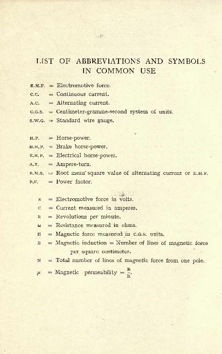
LIST OF ABBREVIATIONS AND SYMBOLSIN COMMON USE
E.M.F. = Electromotive force.
c.c. = Continuous current.
A.C. = Alternating current.
C.G.S. = Centimeter-gramme-second system of units.
S.W.G. = Standard wire gauge.
H.P. = Horse-power.
B.H.P. = Brake horse-power.
E.H.P. = Electrical horse-power.
A.T. = Ampere-turn.
R.M.S. = Root mean square value of alternating current or E.M.F.
P.F. = Power factor.
E = Electromotive force in volts.
c = Current measured in amperes.
R = Revolutions per minute.
v = Resistance measured in ohms.
H = Magnetic force measured in C.G.S. units.
B = Magnetic induction = Number of lines of magnetic force
per square centimeter.
N = Total number of lines of magnetic force from one pole.
ju= Magnetic permeability = -.
OF THE
UNIVERSITYOF
ELEMENTARY DYNAMO DESIGN
CHAPTER I
INTRODUCTORY
1. Electro-Magnetic Induction. All types of dynamosand motors, whether for use with continuous or alternat-
ing currents, are included under the term dynamo-electric
machinery.
The object of dynamo-electric machinery is to convert
mechanical into electrical energy or, being supplied with
electrical energy, to convert it into mechanical.
To convert mechanical into electrical energy is the
function of a generator, which, driven by a prime mover,
gives out current at its terminals. To convert electrical
energy into mechanical is the function of a motor which,
being supplied with current, gives out mechanical energy
at the pulley or coupling.
The principle underlying all these machines is that of
electro-magnetic induction, namely, that whenever a con-
ductor is moved in a magnetic field, so as to cut lines of
magnetic force, an E.M.F. is induced in the conductor.
Magnets used to produce the necessary magnetic field
may be permanent magnets or electro-magnets. Permanent
magnets are pieces of hard steel which, having once been
magnetised, retain a large amount of magnetism. Electro-
magnets are also steel or iron; they carry windings of
copper wire through which an electric current is passed.
B
2 ELEMENTARY DYNAMO DESIGN
The effect of the current is to change for the time being
the steel round which it is flowing into a magnet. This
effect, however, dies out to a great extent when the current
is interrupted.
2. The Magnetic Field. The space surrounding a
magnet and under its influence is known as the magneticfield. Throughout the magnetic field the presence of a
magnetic force can be detected, a small magnet sets itself
in a particular direction owing to the attraction and re-
pulsion of the larger magnet ;small pieces of iron are
themselves magnetised, and either set themselves in special
directions, or if free to move, approach the magnet and
adhere to it.
At all points of the field the force of attraction has
a definite direction, and lines drawn so as to indicate this
direction at every point are known as lines of magneticforce.
A conception of lines of magnetic force plotted through-
out the magnetic field is most useful, and a thorough grasp
of it is indispensable to anyone undertaking the study of
dynamo-electric machinery.
The general direction of the lines of force can easily
be shown experimentally. If a magnet be placed under
a sheet of stiff paper, and iron filings scattered over the
surface of the paper, they will show a tendency to set
themselves along distinct lines. This tendency may be
assisted by "gently tapping the paper, when the filings will
be seen to set themselves along distinct curves all over
the surface. These curves are lines of magnetic force;
they show at any point the direction along which the
magnetic force at that point acts.
Lines of force may be plotted more accurately by using
a small compass needle. A magnet being placed on a
sheet of paper, and the compass needle brought near it,
INTRODUCTORY 3
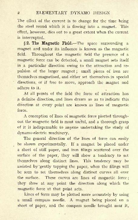
the needle sets itself in a definite direction. The north
and south poles of the compass needle are marked by a
dot on the paper. Assume that the north pole was nearest
the magnet. The compass needle is now moved so that
its north pole coincides with the point formerly occupied
by the south one. The south pole is again marked by a
FIG. i.
dot, the north pole again brought up to this point, and
so on, marking each fresh position of the south pole by a
new dot. Proceeding in this way, and joining all the dots
so obtained, a curve will be placed on the paper which,
starting from the neighbourhood of the south pole of the
magnet, will gradually curve round to the north end (see
Fig. i). Any number of curves can be so drawn until the
whole field is plotted out into lines of magnetic force.
Every line showing at all points the direction in which
a small magnet will set itself, therefore indicates the
direction in which the magnetic force due to the large
magnet acts.
In the experiments above described the lines have been
drawn in one plane only, but they must of course be thoughtof as spreading in all planes round the magnet and filling
the whole of the region of space under its influence. Each
4 ELEMENTARY DYNAMO DESIGN
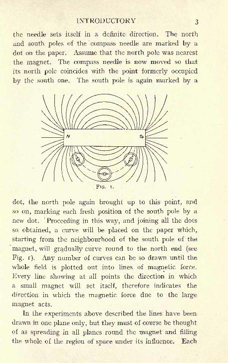
of the lines of magnetic force drawn in this way will emerge
from the magnet near one end, and enter it again in the
neighbourhood of the other. The process cannot be con-
tinued so as to trace the path of the line through the sub-
stance of the magnet itself, but if a hollow coil of wire
carrying a current is substituted for the magnet the same
FIG.
effects are found in the neighbourhood of the coil, and a
diagram of lines of magnetic force can be plotted as
described above. In this case, however, the path of the
lines can be continued through the centre of the solenoid,
and it is then found that each line returns on itself and
forms a closed curve (Fig. 2). The lines curving from a
INTRODUCTORY 5
magnet must, in the same way, be thought of as being
completed through the substance of the magnet so that
each line forms a closed curve.
The next step, and one of the greatest importance, is
to arrange that these lines of force should indicate not
only the direction, but also the magnitude of the magnetic
force. This is done by establishing the convention that
the number of lines of force passing through unit area
shall be made to indicate the strength of the magnetic
field at that point. Thus where the magnetic force is
strong many lines will pass through unit area, that is,
the lines will be crowded close together; on passing into
a weaker region of the field there will be fewer lines in
unit area, that is, the lines of force will spread out and
get farther apart.
It must be clearly understood that it is by convention
that lines of magnetic force are drawn so that the number
passing through unit area indicates the field strength at
that point, but that it is an experimental fact that all lines
of force are closed curves, and that their number being
chosen at any one point proportional to the field strength,
that proportionality will hold at all other points along the
paths of these lines.
3. The Electric and Magnetic Circuits of the
Dynamos. A dynamo-electric machine will usually con-
sist of (i) a part adapted to rotate, and carrying conductors
so arranged that their rotation in a magnetic field will
induce an E.M.F. in them, and of (2) a stationary part
which will produce the necessary magnetic field. Alter-
natively the part producing the magnetic field may be
made to revolve and the part carrying conductors in
which an E.M.F. is generated may be stationary.
In either case there must be in every dynamo two different
circuits to be considered : The magnetic circuit in which
6 ELEMENTARY DYNAMO DESIGN
lines of magnetic force are induced, and the electric circuit
which carries the current.
4. The Electric Circuit. Taking the electric circuit
first, this consists of copper wire or copper bars insulated
from one another and from all other metal by means of
various insulating materials. To all these circuits Ohm's
Law is applicable, i.e., the current flowing through the
circuit is equal to the E.M.F. divided by the resistance.
If c is the current, E the E.M.F., and o> the resistance,
this is expressed by c = -. The resistance is independent&)
of the current flowing through the circuit, but depends on
the material of which it is composed, on its dimensions, and
on its physical state. The resistance of most conductors
for instance increases with an increase of temperature.
The resistance of any conductor varies inversely as
its length and directly as its cross section. Thus, if the
resistance of 100 feet of No. 16 S.W.G. copper wire, the
section of which is -00322 square inch, be -254 ohm,
the resistance of 200 feet will be -254 x 2 = -508 ohm,
and the resistance of 100 feet of No. 14 S.W.G. copper
wire, the section of which is -00503 square inch, will be
00322- x -254 = '162 ohm.
00503
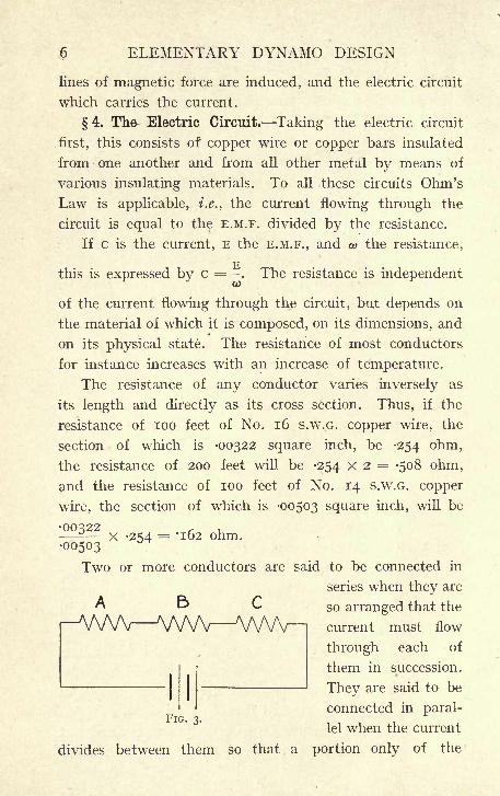
Two or more conductors are said to be connected in
series when they areAE> so arranged that the
-AAAA, WW WA^H current must flow
through each of
them in succession.
They are said to be
connected in paral-
lel when the current
divides between them so that a portion only of the
INTRODUCTORY
FIG. 4.
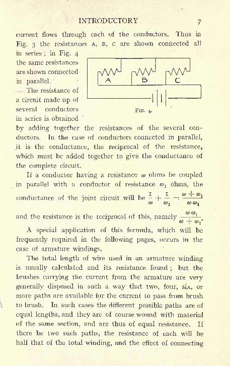
current flows through each of the conductors. Thus in
Fig. 3 the resistances A, B, c are shown connected all
in series;
in Fig. 4
the same resistances
are shown connected
in parallel.
The resistance of
a circuit made up of
several conductors
in series is obtained
by adding together the resistances of the several con-
ductors. In the case of conductors connected in parallel,
it is the conductance, the reciprocal of the resistance,
which must be added together to give the conductance of
the complete circuit.
If a conductor having a resistance co ohms be coupled
in parallel with a conductor of resistance co1 ohms, the
conductance of the ioint circuit will be --\
'- =CO CO-i
and the resistance is the reciprocal of this, namelyJCO COi
0) -f-
A special application of this formula, which will be
frequently required in the following pages, occurs in the
case of armature windings.
The total length of wire used in an armature windingis usually calculated and its resistance found
;but the
brushes carrying the current from the armature are very
generally disposed in such a way that two, four, six, or
more paths are available for the current to pass from brush
to brush. In such cases the different possible paths are of
equal lengths, and they are of course wound with material
of the same section, and are thus of equal resistance. If
there be two such paths, the resistance of each will be
half that of the total winding, and the effect of connecting
8 ELEMENTARY DYNAMO DESIGN
them in parallel will be equivalent to doubling the section,
that is, again halving the resistance. The resistance of
the armature from brush to brush will be j- of the total
resistance of the winding. Similarly for four paths, the
resistance will be yg, and for six paths ^-6 of the resistance
of the whole length of wire, which makes up the electrical
circuits.
The windings of the armature and of the magnetsconsist invariably of copper wires or bars. The use of
this material is dictated by the fact that it has a lower
specific resistance than any other material which can be
commercially produced at a reasonable cost. This property
enables the requisite number of turns of a suitable section
to be got into smaller space than would be the case with
a material of higher specific resistance. The resistance of
electrical circuits on the dynamo must be kept as low as
possible, because the watts lost in heating c 2o> increase
directly as the resistance.
A low resistance can only be obtained with a material
of higher specific resistance by using an increased section,
and an increased section of the winding means increased
dimensions throughout the machine. For instance, iron
has about seven times the specific resistance of copper ;
the windings of a dynamo might be carried out with iron
wire instead of copper, but in order to keep the resistance
at the same value, seven times the section of material
would have to be used. The cost of the iron wire even
at this increased section would be less than that of the
copper actually used, but the dimensions of the machine
would have to be so largely increased to find room for the
increased bulk of windings that the cost, as a whole, wrould
become prohibitive.
5. Electrical Units. The units used in electrical
engineering for measuring E.M.F., current and resistance.
INTRODUCTORY 9
are the Volt, the Ampere and the Ohm. The unit of E.M.F.
is that produced in a conductor of unit length moving
parallel to itself and with unit velocity in a magnetic field
of unit intensity.
On the C.G.S. system this would be the E.M.F. produced
in a conductor one centimeter long, moving with a velocity
of one centimeter per second in a magnetic field, having
one line of magnetic force per square centimeter. This
E.M.F. would be very small, and the volt is, therefore,
taken equal to 100,000,000 such units. The ampere is y-
of the C.G.S. unit of current, and the ohm is equal to
1,000,000,000 C.G.S. units of resistance.
Thus the Volt = io 8 C.G.S. units,
Ampere = lo"1 C.G.S. units,
Ohm = io 9 C.G.S. units,
and an E.M.F. of one volt acting through a resistance of
one ohm gives a current of one ampere.
The rate at which energy is produced or dissipated in
the electric circuit is measured in watts. The watt is the
product of one volt by one ampere. Thus a generator
giving a current of 100 amperes at a pressure of 100 volts
is giving out energy to the circuit at the rate of 100 X 100
= 10,000 watts. The output of the generator is said to
be 10,000 watts or ten kilowatts. Similarly, the electrical
energy put into a resistance is all dissipated as heat;
if
the voltage at the ends of a resistance be io volts, and the
current flowing through it 20 amperes, the rate of such
dissipation will be io X 20 = 200 watts;in general
E x c = watts (i)
but by Ohm's Law
c = .v E = Cft>
substituting in (i)
c 2a) = watts.

io ELEMENTARY DYNAMO DESIGN
The rate at which energy is produced by a prime mover
is usually measured in horse-power. The rate at which
energy is put into a generator will, therefore, be measured
in horse-power, but the rate at which electrical energyflows from its terminals is measured in watts
;it is frequently
convenient to convert one of these units into the other,
and this can be readily done by remembering that one horse-
power is equal to 746 watts.
6. The Magnetic Circuit. Passing now to the magnetic
, circuit, the magnetic field required in dynamos is usually
obtained by means of electro-magnets, that is, masses of
iron or cast steel carrying a winding of copper wire through
which a current circulates, the effect of the current being
to cause lines of magnetic induction to pass round the
magnetic circuit.
The number of turns of wire in a magnet winding multi-
plied by the current flowing through the winding is called
the ampere-turns, and it is found that the number of lines
of magnetic force which are linked with any coil is a function
of the ampere-turns. The number of lines depends also
on the material of which the magnetic circuit is composed.
An air and most other materials the magnetic induction,
that is, the number of lines per square centimeter, is directly
proportional to the number of ampere-turns, but in iron
or steel the induction due to a given number of ampere-
turns is very largely increased. It is, therefore, advisable
to make the magnetic circuit consist, to as large an extent
as possible, of iron.
For example, in static transformers, which are used,
in alternating current work to change from one voltage
to another, there are no moving parts, the magnetic circuit
can be made entirely of iron, and in practice this course
is invariably adopted. In dynamos and motors, however,
one member must be capable of rotation, and as there must,
INTRODUCTORY n
therefore, be mechanical clearance between the rotating
and the stationary parts, it is always necessary to have
an air gap, i.e., a part of the magnetic circuit where the
lines of force have to pass from iron to iron, through air.
Various considerations, which will be noticed in each
separate case, settle what must be the length of magnetic
path in air, but from the fact above noticed, the endeavour
is always to keep this length as short as possible.
There is some similarity between the laws of the magnetic
circuit and those of the electric circuit, in that the magnetic
reluctance of any part of the magnetic circuit varies directly
as the length, and inversely as the cross-section, of the
magnetic path, and depends also on the material used, in
the same way that the electric resistance varies directly
as the length, and inversely as the cross-section, of the con-
ductor, and varies with the material of which it is composed.
The analogy does not, however, hold any farther, for the
resistance is always independent of the current;
the
magnetic reluctance is independent of the magnetic in-
duction only in air and other non-magnetic materials;
in
iron and steel the reluctance varies within wide limits,
according to the magnetic density at which the material
is worked.
It is, however, usual to look upon the magnetic circuit
from a slightly different point of view. If H represents
the magnetic force at any point, and B the magnetic in-
duction at that point, that is the number of lines of magnetic-r>
force per square centimeter, the ratio - is called the per-il
meability of that part of the circuit. This ratio is usually
denoted by the Greek letter//,.
In air and other non-magnetic materials, /JL*is equal
to unity ;that is, B, the magnetic induction, and H, the
magnetic force, have the same numerical value. In iron
12 ELEMENTARY DYNAMO DESIGN
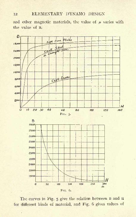
and other magnetic materials, the value of ^ varies with
the value of B.
iao 140
50 100 150
FIG. 6.
200 250 300
The curves in Fig. 5 give the relation between B and H
for different kinds of material, and Fig. 6 gives values of
INTRODUCTORY 13
the permeability /* for higher values of B where the scales
become such as to make the plotting of the B H curve incon-
venient. By the use of these curves it is easy to find the
corresponding value of H for any given value of magnetic
induction B.
In dynamo design, the problem of the magnetic circuit
usually occurs as follows : The total number of lines of
magnetic force required is known, and also the area and
length of the different parts of the circuit, and it is required
to find a suitable winding of the magnet coils to give the
total flux required.
If A be the area of any part of the magnetic circuit,
in square centimeters, and L its length in centimeters,
and if N be the total number of lines of force required,
Nthen - = B the number of lines per square centimeter.
A
In air, H, the magnetic force = B, in iron or steel, the value
of H corresponding to any value of B is found from the
curves (see Fig. 5). Then L X H is the magneto-motive
force required for this part of the circuit, and the sum of
the terms L H found for every part of the circuit will be the
total magneto-motive force to be provided.
Again, the number of turns of wire wound on any part
of the circuit, multiplied by the current measured in amperes,
flowing in the winding, is called the ampere turns in the
winding, and this is proportional to the magneto-motive
force H L = where A T represents ampere-turns
or A T = H L, that is, the ampere-turns required to give
a magneto-motive force H L are equal to - - H L. The value4
of - -is very nearly -8, and it is sufficient for all practical
purposes to remember that for any part of the magnetic
14 ELEMENTARY DYNAMO DESIGN
circuit in which the magnetic force has the value H; and
the length of which is L, the ampere-turns required will
be -8 HL, and that the total ampere-turns required will be
obtained by treating separately each part of the circuit
having different values of H, and adding together the
number of ampere-turns required for each.
7. Iron Losses Hysteresis and Eddy Currents. In
those iron parts of any machine where the magnetic in-
duction varies at different times, there will be present
losses due to eddy currents and to hysteresis. The former
are due to the fact that the metal cutting magnetic lines
has induced in it an E.M.F. which gives rise to currents
flowing in the mass of the metal itself. These currents
flowing against the resistance to give rise to a loss of watts
equal to c 2 w. This loss may easily become a serious
one.
If, for instance, the armature core of a dynamo or motor
were made of solid iron, the losses due to eddies would be
extremely large, in fact might easily amount to manytimes the whole output of the machine. This effect is
minimised by laminating the iron so as to increase the
resistance and thus diminish the currents. For example,
the armature core of a dynamo is made, not of a solid block,
but of thin discs punched to the proper shape, and threaded
on the shaft or on the spider. These discs, being more or
less thoroughly insulated from one another, oppose large
resistance to the currents which would tend to flow in
directions parallel to the shaft. It can be shown that the
watts lost in eddy currents vary directly as the square of
the frequency, i.e., as the square of the number of reversals
of the magnetic force per second.
When iron is magnetised, the value of B corresponding
to any given value of H varies not only with the quality
of the material, but depends also on the previous history
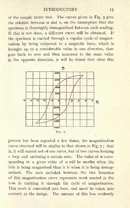
INTRODUCTORY
of the sample under test. The curves given in Fig. 5 give
the relation between H and B, on the assumption that the
specimen is thoroughly demagnetised between each reading.
If this is not done, a different curve will be obtained. If
the specimen is carried through a regular cycle of magnet-
isation by being subjected to a magnetic force, which is
brought up to a considerable value in one direction, then
goes back to zero and then increases to the same value
in the opposite direction, it will be found that after this
b
-5H
process has been repeated a few times, the magnetisation
curve obtained will be similar to that shown in Fig. 7 ;that
is, it will consist not of one curve, but of two curves forminga loop and enclosing a certain area. The value of B corre-
sponding to a given value of H will be smaller when the
iron is being magnetised than it is when it is being demag-netised. The area included between the two branches
of this magnetisation curve represents work wasted in the
iron in carrying it through the cycle of magnetisation.
This work is converted into heat, and must be taken into
account in the design. The amount of this loss evidently
16 ELEMENTARY DYNAMO DESIGN
depends on the higher value of B to which the magnetisation
of the iron is carried. It depends also, to a very large extent,
on the magnetic quality of the iron used.
It is frequently assumed that the hysteresis for any given
sample is proportional to Bl6,and this is probably suffi-
ciently accurate within the range used in ordinary practice,
although the accuracy of this formula for wide ranges has
been largely disputed. The hysteresis loss being constant
for one cycle will naturally vary as the total number of the
reversals per second.
It should be noted that whilst the c 2&> losses in the
electric circuit are constantly present so long as the current
c is flowing through the circuit, the iron losses in the
magnetic circuit, whether eddy current losses or hysteresis,
occur only at such times as the magnetic field is varying
either in intensity or in direction.
Thus in the field magnets of a dynamo excited with
continuous current, when once the excitation has reached
a constant value, the magnetic field also remains constant,
and there is no loss from either of the above causes; in the
iron body of a rotating armature, on the other hand, each
element of the core is being constantly carried from one
magnetic field to others of different intensities and direc-
tions, and therefore both eddy losses and hysteresis have
to be reckoned with.
8. Value of E.M.F. Generated. The unit of E.M.F.
is defined (see p. 9) as that produced in a conductor of
unit length, moving in a direction at right angles to its
length and to the lines of force and with unit velocity in
a magnetic field of unit density, i.e., in a field having one
line of magnetic force passing through each unit area. The
E.M.F. increases with the length of conductor, the velocity,
and the density of the magnetic field. Therefore, a con-
ductor of length / moving with velocity v in a field having-
INTRODUCTORY 17
B lines of force per unit area will have generated in it
v x / x B units of E.M.F.
Again, since v is the velocity, the distance passed over
by any point of the conductor in unit time is v, and vl
represents the area swept over by the conductor in this
time, and since there are B lines per unit area, the total
number of lines of magnetic force cut by the conductor
in unit time is v X I X B, but this is the expression already
found for the value of the E.M.F., and therefore the E.M.F.
is equal to the number of lines of magnetic force cut bythe conductor in unit time. If, as is usual, the volt be used
as the unit of E.M.F., and the second as the unit of time,
the E.M.F. generated in a conductor moving through a
magnetic field will be equal to the total number of lines
cut per second, divided by 100,000,000 (io8), since this is
the number of C.G.S. units of E.M.F. in one volt.
9. Electric and Magnetic Properties of Materials.
Numerical values of the resistance of the copper used can
be calculated from the resistance of one cubic inch of copper= -000000667 ohm, but they are more conveniently taken
from a table of the properties of copper wire, such as are
published in many textbooks, and by most manufacturers
of cable and wire. A specimen table is given in the Appendix.
The resistance of copper increases by about -38% per degree
Centigrade, or -21% per degree Fahrenheit, and it is usual
to calculate the resistance of the copper windings of a
dynamo at the highest temperature which it is expected
the machine will reach. Another column is therefore
added to the table in which 20% is added to the resistance,
this allowance being sufficient to cover the increase of
resistance, due to a temperature of about 130 F., and
also the increase due to the stretching of the wire, which
almost invariably takes place whilst it is being wound on
the machine.
c
i8 ELEMENTARY DYNAMO DESIGN
The choice of material from which the magnetic circuit
shall be constructed is very limited. The fact that the
permeability of iron is much greater than that of anyother known material compels the use of iron in some
form or another in all parts of the magnetic circuit. Magnetsare therefore built of wrought iron, cast steel, or cast iron.
The magnetic properties of the iron used vary considerably
in different specimens, the curves given in Fig. 5, however,
are the mean of those usually obtained in practice and will
be used throughout the calculations.
10. Insulating Materials. It is not only necessary
to provide in the copper windings a free path for the electric
current ;it is also necessary that means should be taken
to prevent the current from straying through paths where
it is not required. For this purpose, insulating materials of
various kinds are used. There are many materials which
offer a large resistance to the passage of electricity ; wood,
paper, fabrics of silk or cotton, ebonite, glass, marble,
slate, mica, and asbestos, for example, are all used in
different classes of electrical work as insulators.
Insulation may fail by allowing the electric current
to pass through its substance, or to creep over its surface;
the presence of moisture (water is a comparatively goodconductor of electricity) or of dirt will spoil the insulating
properties of most of the materials mentioned above by
allowing the current to creep through them or over their
surfaces.
The resistance which a material opposes to the current
passing through it or over its surface can be measured
in ohms by any of the well-known methods for measuring
high resistances. For instance, the resistance measured
between the conducting circuit of a dynamo and some
metal part of the frame, not intended to carry current,
indicates the amount of current which would leak through
INTRODUCTORY 19
to the frame under working conditions. This resistance is
called the insulation resistance of the machine, and is
usually measured in megohms, a megohm being equal to
one million ohms.
In addition to this it is found that any given thickness
of any particular insulating material will stand only a
certain E.M.F. applied to its opposite surfaces;
if this be
exceeded the insulation breaks down, the material is
mechanically punctured, a spark passes, and an arc maybe maintained.
However high the insulation resistance of any apparatus
may be, it is no guarantee that it will not break down in
this way. In addition to a high insulation resistance, the
material used must also have sufficient dielectric strength
to resist the E.M.F. at which the machine is to be used.
A material has a good dielectric strength, a moderate
thickness of which requires considerable E.M.F. to break
it down.
The chief requirements of a good insulating materia
then, are, that it should give a high insulation resistance
and have good dielectric strength ;it should not be hygro-
scopic, that is, it should not readily absorb moisture.
Mechanical strength is required in many parts of a dynamo,and in some places the material must also be flexible, so
that it can be bent to the required shape without breaking
or cracking, and it must stand a fairly high temperature
without deteriorating.
There is no single material which even approximate?''
fulfils all these conditions. Cotton, either wrapped directly
on the wire or used in the form of tape, is useful because
of its flexibility, but it has very little dielectric strength,
and readily absorbs moisture. Silk has much the same
properties as cotton;
it is a better insulator and is some-
times used in dynamos where space is limited, as a thinner
20 ELEMENTARY DYNAMO DESIGN
covering of silk can be put on the wire than is practicable
with cotton. The very much greater cost of silk, however
prohibits its general use. Paper, cardboard, and various
materials on the market, which are made from wood pulp
or similar preparations, are tough and stand fairly rough
handling in the building of a machine;most of them,
however, absorb moisture. Mica is excellent in its dielectric
strength and is not very hygroscopic. It is, however,
unsuitable for many purposes, because of its want of
flexibility. India-rubber and vulcanite soften at the
temperatures to which a dynamo rises, and preparations
such as fibre and many other manufactured insulations
warp when exposed to these temperatures.
The usual method of insulating the circuits in the dynamois to use a cotton covering on the conductor, either braided
or simply double cotton-covered. This is by itself sufficient
to insulate from one another the turns of the coil. Corners
and bends are, however, protected by a further wrapping
of cotton tape, and to counteract the moisture-absorbing
properties of the cotton the coils are frequently dipped
in varnish and baked before being put on to the machine.
The metal parts of the machines, whether armature core
or spools for the field coils, are further insulated before
the coils are put on. For pressures up to 500 volts, paper
or similar material such as presspahn, leatheroid, etc., is
found to be sufficient, but for machines to be worked at high
voltages, or for such as will be subject to be worked in
very high temperatures, or to be exposed to damp, mica
is the best material for this purpose.
CHAPTER II
VARIOUS TYPES OF DYNAMOS AND MOTORS
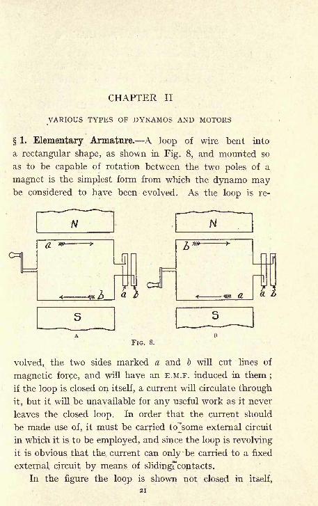
1. Elementary Armature. A loop of wire bent into
a rectangular shape, as shown in Fig. 8, and mounted so
as to be capable of rotation between the two poles of a
magnet is the simplest form from which the dynamo maybe considered to have been evolved. As the loop is re-
N
a *>
FIG. 8.
volved, the two sides marked a and b will cut lines of
magnetic force, and will have an E.M.F. induced in them;
if the loop is closed on itself, a current will circulate through
it, but it will be unavailable for any useful work as it never
leaves the closed loop. In order that the current should
be made use of, it must be carried to^some external circuit
in which it is to be employed, and since the loop is revolving
it is obvious that the current can only 'be carried to a fixed
external circuit by means of slidingrcontacts.
In the figure the loop is shown not closed in itself,
21
22 ELEMENTARY DYNAMO DESIGN
but having its ends connected to two rings a and b;
on
each of these rings rests a copper or carbon brush which
collects the current from the ring, and carries it to the
outer circuit.
A little consideration will show that the current pro-
duced by such an apparatus will be constantly varying
in direction. If the direction of rotation be such that the
top of the loop a is moving from back to front of the paper,
i.e., towards the observer, the E.M.F. induced in it will be
from left to right, in the bottom bar it will be from right
to left. Thus the current will enter the external circuit at
the ring a and leave it at b; i.e., the brush at a will be the
positive (+ ) terminal, that at b the negative ( ) terminal.
But when half a revolution has been accomplished, the
loop will have got into the position shown at A, Fig. 8, and
the ring b will now be positive, the ring a negative, and
the direction of the current in the external circuit will be
reversed. This reversal will take place at every half
revolution of the loop. The current generated in this
way is known as an alternating current, and is constantly
varying in magnitude and direction.
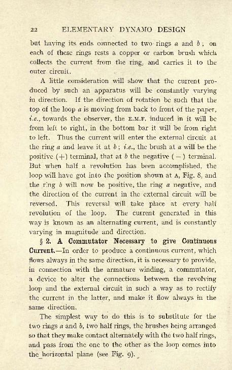
2. A Commutator Necessary to give Continuous
Current. In order to produce a continuous current, which
flows always in the same direction, it is necessary to provide,
in connection with the armature winding, a commutator,
a device to alter the connections between the revolving
loop and the external circuit in such a way as to rectify
the current in the latter, and make it flow always in the
same direction.
The simplest way to do this is to substitute for the
two rings a and b, two half rings, the brushes being arranged
so that they make contact alternately with the two half rings,
and pass from the one to the other as the loop comes into
the horizontal plane (see Fig. 9).
OF
FIG. 9.
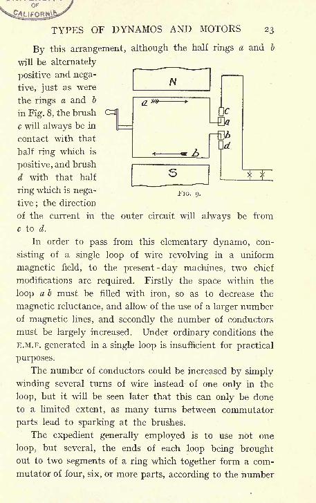
TYPES OF DYNAMOS AND MOTORS 23
By this arrangement, although the half rings a and b
will be alternately
positive and nega-
tive, just as were
the rings a and b
in Fig. 8, the brush
c will always be in
contact with that
half ring which is
positive, and brush
d with that half
ring which is nega-
tive;the direction
of the current in the outer circuit will always be from
c to d.
In order to pass from this elementary dynamo, con-
sisting of a single loop of wire revolving in a uniform
magnetic field, to the present-day machines, two chief
modifications are required. Firstly the space within the
loop a b must be filled with iron, so as to decrease the
magnetic reluctance, and allow of the use of a larger number
of magnetic lines, and secondly the number of conductors
must be largely increased. Under ordinary conditions the
E.M.F. generated in a single loop is insufficient for practical
purposes.
The number of conductors could be increased by simply
winding several turns of wire instead of one only in the
loop, but it will be seen later that this can only be done
to a limited extent, as many turns between commutator
parts lead to sparking at the brushes.
The expedient generally employed is to use not one
loop, but several, the ends of each loop being broughtout to two segments of a ring which together form a com-
mutator of four, six, or more parts, according to the number
ELEMENTARY DYNAMO DESIGN
of loops. Thus the commutator is evolved, consisting
of many segments insulated from one another and built
up to form a ring or cylinder on which the brushes rest.
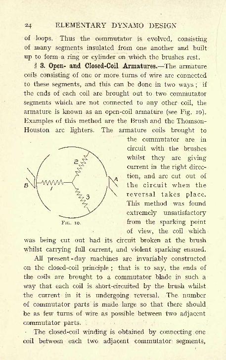
3. Open- and Closed-Coil Armatures. The armature
coils consisting of one or more turns of wire are connected
to these segments, and this can be done in two ways ;if
the ends of each coil are brought out to two commutator
segments which are not connected to any other coil, the
armature is known as an open-coil armature (see Fig. 10).
Examples of this method are the Brush and the Thomson-
Houston arc lighters. The armature coils brought to
the commutator are in
circuit with the brushes
whilst they are giving
current in the right direc-
tion, and are cut out of
the circuit when the
reversal takes place.
This method was found
extremely unsatisfactory
from the sparking point
of view, the coil which
was being cut out had its circuit broken at the brush
whilst carrying full current, and violent sparking ensued.
All present-day machines are invariably constructed
on the closed-coil principle ;that is to say, the ends of
the coils are brought to a commutator blade in such a
way that each coil is short-circuited by the brush whilst
the current in it is undergoing reversal. The number
of commutator parts is made large so that there should
be as few turns of wire as possible between two adjacent
commutator parts.
The closed-coil winding is obtained by connecting one
coil between each two adjacent commutator segments,
FIG. 10.
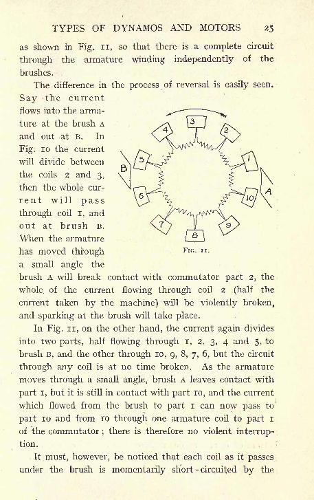
TYPES OF DYNAMOS AND MOTORS
FIG. ii.
as shown in Fig. n, so that there is a complete circuit
through the armature winding independently of the
brushes.
The difference in the process of reversal is easily seen.
Say the current
flows into the arma-
ture at the brush A
and out at B. In
Fig: 10 the current
will divide between
the coils 2 and 3,
then the whole cur-
ren t will pass
through coil i, and
out at brush B.
When the armature
has moved through
a small angle the
brush A will break contact with commutator part 2, the
whole of the current flowing through coil 2 (half the
current taken by the machine) will be violently broken,
and sparking at the brush will take place.
In Fig. n, on the other hand, the current again divides
into two parts, half flowing through I, 2, 3, 4 and 5, to
brush B, and the other through 10, 9, 8, 7, 6, but the circuit
through any coil is at no time broken. As the armature
moves through a small angle, brush A leaves contact with
part I, but it is still in contact with part 10, and the current
which flowed from the brush to part I can now pass to
part 10 and from 10 through one armature coil to part I
of the commutator;there is therefore no violent interrup-
tion.
It must, however, be noticed that each coil as it passes
under the brush is momentarily short-circuited by the
26 ELEMENTARY DYNAMO DESIGN
brush, and that during this period of short circuit the
direction of the current in the coil is reversed. For instance,
in the position shown in the figure the current flows from
part 10 to part 9, through the coil connecting these parts,
but when the rotation of the armature has carried this
coil into the upper half of the figure, the direction of the
current being still from brush A to brush B, the direction
in the coil under observation will now be from part 9 to
part 10;
the current will have changed its direction as
the coil passed under the brush.
If the machine is properly proportioned, this reversal
will be effected smoothly, but if the proper proportions
are not observed, the reversal of the current will not have
been completed by the time the commutator part leaves
the brush and sparking at the brushes will ensue.
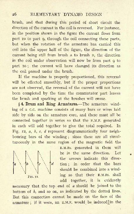
4. Drum and Ring1 Armatures. The armature wind-
ing of a c.c. machine consists of many bars or wires laid
side by side on the armature core, and these must all be
connected together in series so that the E.M.F. generated
in each will add together to give the total required. In
Fig. 12, a, b, c, d represent diagrammatically four neigh-
bouring bars of the winding ;since these are all simul-
taneously in the same region of the magnetic field the
E.M.FS. generated in them will
be in the same direction. Let
the arrows indicate this direc-
V tion;
in order that the bars
should be combined into a wind-
ing so that their E.M.FS. shall
add together, it is evidently
necessary that the top end of a should be joined to the
bottom of b, and so on, as indicated by the dotted lines.
But this connection cannot be made on the face of the
armature;
if it were, an E.M.F. would be induced]Hn the
FIG. 12.
TYPES OF DYNAMOS AND MOTORS 27
connecting wire opposing that in the bars, and the total
result would be no E.M.F. at the ends of the winding.
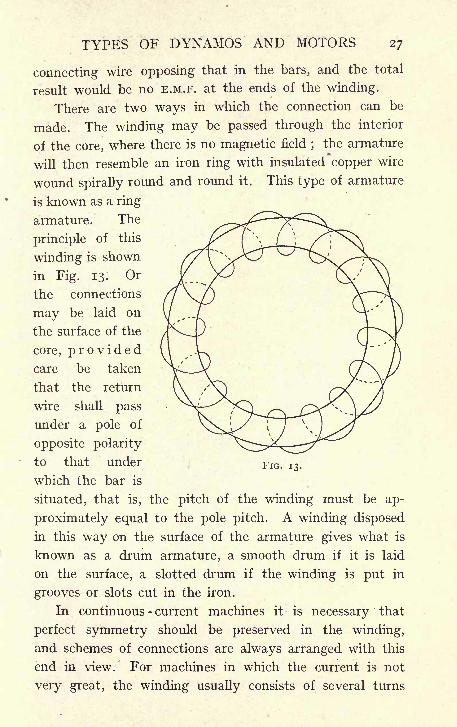
There are two ways in which the connection can be
made. The winding may be passed through the interior
of the core, where there is no magnetic field;the armature
will then resemble an iron ring with insulated copper wire
wound spirally round and round it. This type of armature
is known as a ring
armature. The
principle of this
winding is shown
in Fig. 13. Or
the connections
may be laid on
the surface of the
core, providedcare be taken
that the return
wire shall pass
under a pole of
opposite polarity
to that under
which the bar is
situated, that is, the pitch of the winding must be ap-
proximately equal to the pole pitch. A winding disposed
in this way on the surface of the armature gives what is
known as a drum armature, a smooth drum if it is laid
on the surface, a slotted drum if the winding is put in
grooves or slots cut in the iron.
In continuous - current machines it is necessary that
perfect symmetry should be preserved in the winding,
and schemes of connections are always arranged with this
end in view. For machines in which the current is not
very great, the winding usually consists of several turns
FIG. 13.
28 ELEMENTARY DYNAMO DESIGN
of copper wire insulated with a" cotton covering. The wire
is generally wound into coils having the necessary number
of turns, and made into a suitable shape, and the finished
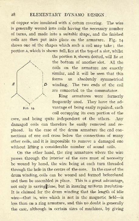
coils are then put into place on the armature. Fig. 14
shows one of the shapes which such a coil may take;
the
portion A, which is shown full, lies at the top of a slot, whilst
the portion B, shown dotted, will lie at
the bottom of another slot. All the
coils on the armature are exactly
similar, and it will be seen that this
forms an absolutely symmetrical
winding. The two ends of the coil
are connected to the commutator.
Ring armatures were formerly
frequently used. They have the ad-
FIG. 14. vantage of being easily repaired, each
coil occupying its own portion of the
core, and being quite independent of the others. Any
damaged coils can therefore be easily removed and re-
placed. In the case of the drum armature the end con-
nections of one coil cross below the connections of manyother coils, and it is impossible to remove a damaged one
without lifting a considerable number of sound coils.
On the other hand, the ring armatures where the wire
passes through the interior of the core must of necessity
be wound by hand, the wire being at each turn threaded
through the hole in the centre of the core. In the case of the
drum winding, coils can be wound and formed beforehand
and then be assembled in place. This is a great advantage,
not only in savingjtime, but in insuring uniform insulation-
It is claimed for the drum winding that the length of idle
wire that is, wire which is not in the magnetic field is
less than on a ring armature, and this no doubt is generally
the case, although in certain sizes of machines, by giving
TYPES OF DYNAMOS AND MOTORS 29
the core a proper section, the amount of idle wire in a ring
armature fs not much greater than on the corresponding
drum.
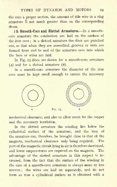
5. Smooth-Core and Slotted Armatures. In a smooth-
core armature the conductors are laid on the surface of
the iron core;
in a slotted armature the discs are punched
out, so that when they are assembled, grooves or slots are
formed from end to end of the armature core into which
the bars or wires are laid.
In Fig. 15 discs are shown for a smooth-core armature
(A) and for a slotted armature (B).
In a smooth-core armature the diameter of the iron
core must be kept small enough to ensure the necessary
A FIG. 15. B
mechanical clearance, and also to allow room for the copper
and the necessary insulation.
In the slotted armature the winding lies below the
cylindrical surface of the armature, and the iron of
the armature can, therefore, be brought close to that of the
magnets, mechanical clearance only being required. The
part of the magnetic circuit lying in air is therefore shortened,
and fewer ampere-turns are required on the magnets. The
advantage of the slotted armature in this respect is in-
creased, from the fact that the surface of the winding in
the case of a smooth-core armature is always more or less
uneven;
the wires are laid on separately, and do not
form as true a cylindrical surface as is obtained with a
30 ELEMENTARY DYNAMO DESIGN
slotted armature;
the mechanical clearance to be allowed
is, therefore, greater with smooth-core than with slotted
armatures.
Mechanically also, the construction employing, a slotted
armature is much more satisfactory. On a smooth-core
machine, the wires are held in place only by friction, or
by driving horns, that is, projections, usually of wood,which are let into the core at intervals in order to give a
direct drive to the wires. It is evidently much better to
have the wires positively driven by being placed in slots,
and, as a matter of fact, the advantage is even greater than
would at first sight appear, for it can be shown, and it has
been proved experimentally, that wires buried in the iron
of the core are relieved of practically all the magnetic pull
to which they would otherwise be subject. This is easily
realised when it is considered that there is only a verysmall magnetic field in the slots, and that practically the
whole of the lines of magnetic force are carried by the
teeth;thus the magnetic circumferential drag, which in
a smooth-core armature is taken by the wires, is in a slotted
armature transferred to the teeth.
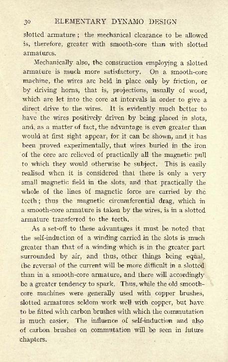
As a set-off to these advantages it must be noted that
the self-induction of a winding carried in the slots is much
greater than that of a winding which is in the greater part
surrounded by air, and thus, other things being equal,,
the reversal of the current will be more difficult in a slotted
than in a smooth-core armature, and there will accordingly
be a greater tendency to spark. Thus, while the old smooth-
core machines were generally used with copper brushes,
slotted armatures seldom work well with copper, but have
to be fitted with carbon brushes with which the commutation
is much easier. The influence of self-induction and also
of carbon brushes on commutation will be seen in future
chapters.
TYPES OF DYNAMOS AND MOTORS 31
6. Bipolar and Multipolar Machines. The magnet
system in which an armature is to run may be arranged
with one or more pairs of poles.
In alternating- current work, the number of poles is
rigidly fixed by the relation between the speed of rotation
and the periodicity of the current;
in continuous-current
work there is no such rigidity and there is, therefore, much
more latitude in the choice of the number of poles.
Dynamos having two poles only are said to be of the
Bipolar type, and those having more than two poles, of
the Multipolar type.
For many years continuous - current generators and
motors were most frequently made of the bipolar type.
Multipolar machines are now generally used, and a two-
pole construction is uncommon. The necessity for in-
creasing the number of poles became apparent as soon as
slotted armatures were introduced, because the decreased
number of ampere-turns required on the magnets gave
an undesirable preponderance to the armature ampere-
turns. As will be seen, strong armature reaction is undesir-
able, and by increasing the number of poles the armature
ampere-turns per pole that is, the armature-turns opposing
the ampere-turns on one magnet coil can be diminished,
hence the general use of multipolar machines. It is, never-
theless, true that in small machines where the armature
ampere-turns are in any case not excessive, the two-pole
construction could in many cases be adopted. It is found,
however, that a saving in material can generally be effected
by using four instead of two poles, and most machines of
recent construction of any size larger than a toy have at
least four poles.
In the early days of dynamo-electric machinery manydifferent types of armatures and field magnets were in use.
At the present time multipolar magnets with slotted drum-
32 ELEMENTARY DYNAMO DESIGN
wound armature are almost universal, and it is to machines
of this type that the following descriptions and calcula-
tions will chiefly refer.
The general appearance of a continuous-current dynamoof the multipolar type with a slotted drum armature, such
as would be constructed at present, is shown in Fig. 24
at the end of this chapter, and an outline sketch of the
machine with the names applied to the different parts is
given in Fig. 25 ;reference to this diagram will enable the
descriptions in the ensuing chapters to be readily followed.
The winding of a slotted drum armature may be carried
out with round wire, or with bars of a square or rectangular
section. If the current to be carried is not large, and the
section of the conductor is consequently small, round
wires are preferred. A square or rectangular wire would,
it is true, pack closer in the slot, and thus allow a larger
section of copper to be got into the same space, but square
wires of small section are very apt to get a twist, especially
where any bending occurs, and instead of lying parallel
to one another, will, on account of the twist, have a great
tendency to cut through the insulation at the corner, and
cut into one another;this disadvantage is altogether absent
in the case of round wires, and they are consequently
generally employed for windings of small current-carry-
ing capacity.
When, however, the size of wire becomes so large as
to make it difficult to bend, bars preferably of a rectangular
section are used ;with the increased section the number
of turns per coil naturally become less, and it is therefore
practicable to make each turn out of one bar and con-
nect the separate turns by means of soldered joints.
In either case, whether made of wire or bars, all the
coils must be of exactly the same shape in order to ensure
that the winding shall be symmetrical, and, since it is also
TYPES OF DYNAMOS AND MOTORS 33
necessary that the two sides of a coil should be simul-
taneously under poles of opposite polarity (see section 4
of this chapter), the span of the coil must be equal to the
pole pitch, and it will in general span over several slots;
arrangement must therefore be made so that the end
connections of the coils outside the slots pack together
without interfering with the wires coming out of inter-
mediate slots. This is done by shaping the coils as in
Fig. 14 ;the bar' shown full (as we have said) lies at the
top of the slot, the part dotted at the bottom of another
slot, whilst of the end connections the part shown full
crosses over and lies in a plane above the dotted parts of
the coils coming out of intermediate slots.
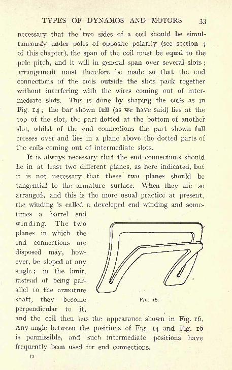
It is always necessary that the end connections should
lie in at least two different planes, as here indicated, but
it is not necessary that these two planes should be
tangential to the armature surface. When they are so
arranged, and this is the more usual practice at present,
the winding is called a developed end winding and some-
times a barrel end
winding. The two
planes in which the
end connections are
disposed may, how-
ever, be sloped at any
angle ;in the limit,
instead of being par-
allel to the armature
shaft, they become
perpendicular to it,
and the coil then has the appearance shown in Fig. 16.
Any angle between the positions of Fig. 14 and Fig. 16
is permissible, and such intermediate positions have
frequently been used for end connections.
FIG. 16.
34 ELEMENTARY DYNAMO DESIGN
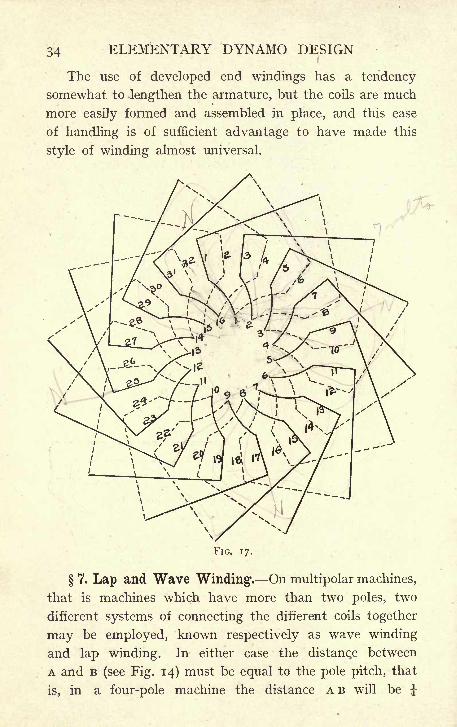
The use of developed end windings has a tendency
somewhat to lengthen the armature, but the coils are much
more easily formed and assembled in place, and this ease
of handling is of sufficient advantage to have made this
style of winding almost universal.
FIG. 17.
7. Lap and Wave Winding. On multipolar machines,
that is machines which have more than two poles, two
different systems of connecting the different coils together
may be employed, known respectively as wave winding
and lap winding. In either case the distance between
A and B (see Fig. 14) must be equal to the pole pitch, that
is, in a four-pole machine the distance A B will be J-
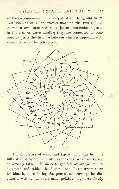
TYPES OF DYNAMOS AND MOTORS 35
of the circumference;
in a six-pole it will be-J-,
and so on.
But whereas in a lap -wound machine the two ends of
A and B are connected to adjacent commutator parts,
in the case of wave winding they are connected to com-
mutator parts the distance between which is approximately
equal to twice the pole pitch.
FIG. 18.
The properties of wave and lap winding can be more
fully studied by the help of diagrams and what are known
as winding tables. In order to get full advantage of such
diagrams and tables the student should construct them
for himself, since during the process of drawing the dia-
gram or writing the table many points emerge very clearly
36 ELEMENTARY DYNAMO DESIGN
which are to a certain extent obscured by the overlapping
of coils on the finished diagram or table.
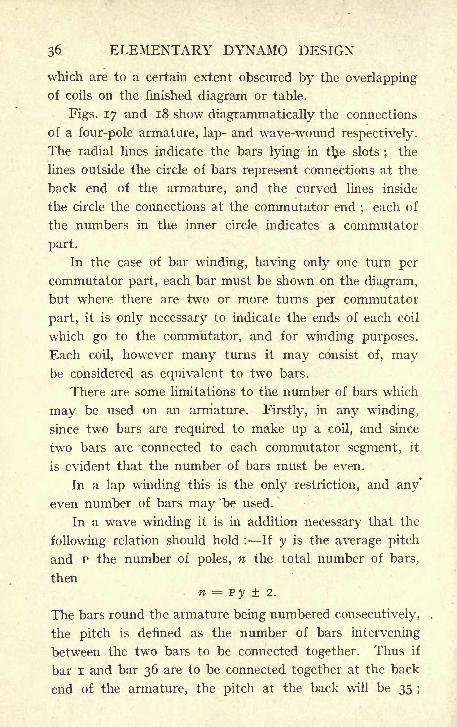
Figs. 17 -and 18 show diagrammatically the connections
of a four-pole armature, lap- and wave-wound respectively.
The radial lines indicate the bars lying in ttye slots;
the
lines outside the circle of bars represent connections at the
back end of the armature, and the curved lines inside
the circle the connections at the commutator end;each of
the numbers in the inner circle indicates a commutator
part.
In the case of bar winding, having only one turn per
commutator part, each bar must be shown on the diagram,
but where there are two or more turns per commutator
part, it is only necessary to indicate the ends of each coil
which go to the commutator, and for winding purposes.
Each coil, however many turns it may consist of, maybe considered as equivalent to two bars.
There are some limitations to the number of bars which
may be used on an armature. Firstly, in any winding,
since two bars are required to make up a coil, and since
two bars are connected to each commutator segment, it
is evident that the number of bars must be even.
In a lap winding this is the only restriction, and any*
even number of bars may be used.
In a wave winding it is in addition necessary that the
following relation should hold : If y is the average pitch
and P the number of poles, n the total number of bars,
thenn = py 2.
The bars round the armature being numbered consecutively,
the pitch is defined as the number of bars intervening
between the two bars to be connected together. Thus if
bar I and bar 36 are to be connected together at the back
end of the armature, the pitch at the back will be 35 ;
TYPES OF DYNAMOS AND MOTORS 37
the front pitch may be the same as the back or it maydiffer from it
;in either case, the term average pitch, as
used above, is to be interpreted as the mean of the back
and front pitch.
In a four-pole machine P = 4, let the average pitch
be 36, then P y = 144, and 142 or 146 are possible numbers
for a wave winding, but 144 is not. In the same way a
six-pole machine may have an average pitch of 70, in this
case P y = 420 ;then 418 and 422 are possible numbers
for a wave winding, but 420 is not. Choosing slightly
different values for the pitch, say 69 and 71, values of
P y = 414 and 426 are obtained, and it is found that 412
or 416, 424 or 428 bars may be used. So that for a six-pole
wave winding requiring about 420 bars, it is possible to use
412, 416, 418, 422, 424, or 428 bars, but 414, 420, and 426
are not practicable numbers.
8. Armature Winding Tables. The fact already
noticed that the end connections must lie in two different
planes is clearly brought out in Figs. 17 and 18, where
the full lines show bars at the top of the slots and
their connections, and the dotted lines show bars at the
bottom of the slots and their connections. It is seen that
the end connections cross one another at many points,
but that in all cases it is a full line that crosses a dotted
line ;in no case do full lines cross one another or dotted
lines cross one another; the significance of this being
that while the two layers of connections cross one another
all the bars in either of the layers lie parallel to one another.
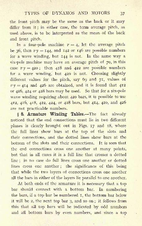
At both ends of the armature it is necessary that a top
bar should connect with a bottom bar. In numberingthe bars, if a top bar be numbered I, the bottom bar below
it will be 2, the next top bar 3, and so on;
it follows from
this that all top bars will be indicated by odd numbers
and all bottom bars by even numbers, and since a top
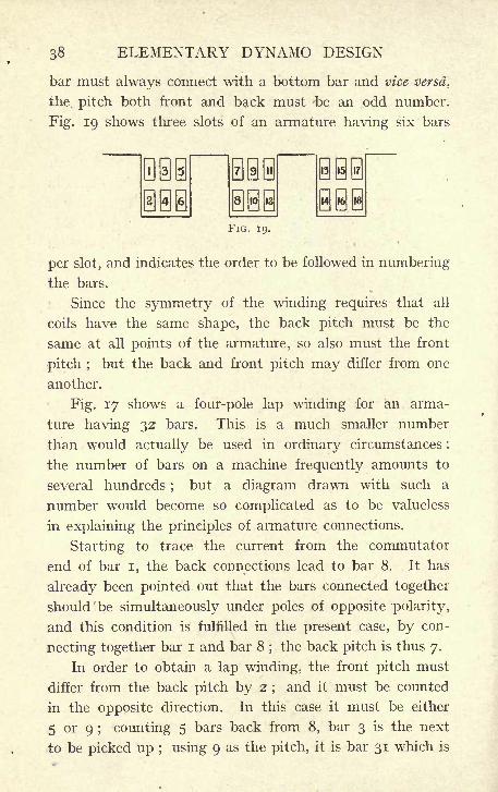
ELEMENTARY DYNAMO DESIGN
bar must always connect with a bottom bar and vice -versa,
the pitch both front and back must -be an odd number.
Fig. 19 shows three slots of an armature having six bars
FIG. 19.
per slot, and indicates the order to be followed in numbering
the bars.
Since the symmetry of the winding requires that all
coils have the same shape, the back pitch must be the
same at all points of the armature, so also must the front
pitch ;but the back and front pitch may differ from one
another.
Fig. 17 shows a four-pole lap winding for an arma-
ture having 32 bars. This is a much smaller number
than would actually be used in ordinary circumstances :
the number of bars on a machine frequently amounts to
several hundreds ;but a diagram drawn with such a
number would become so complicated as to be valueless
in explaining the principles of armature connections.
Starting to trace the current from the commutator
end of bar i, the back connections lead to bar 8. It has
already been pointed out that the bars connected together
should 'be simultaneously under poles of opposite polarity,
and this condition is fulfilled in the present case, by con-
necting together bar I and bar 8;the back pitch is thus 7.
In order to obtain a lap winding, the front pitch must
differ from the back pitch by 2;and it must be counted
in the opposite direction. In this case it must be either
5 or 9 ; counting 5 bars back from 8, bar 3 is the next
to be picked up ; using 9 as the pitch, it is bar 31 which is
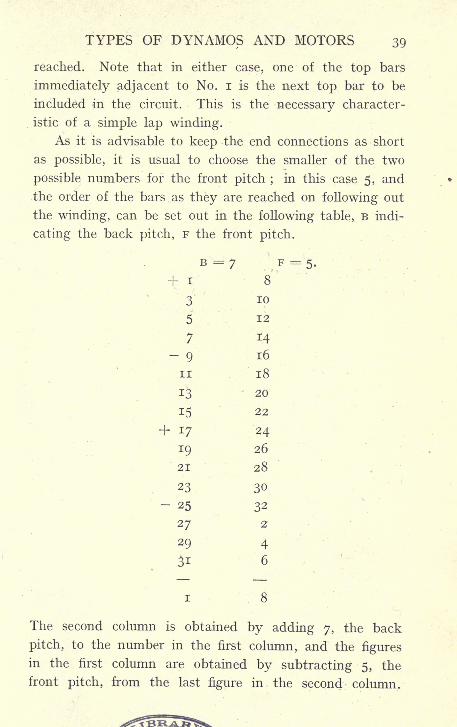
TYPES OF DYNAMOS AND MOTORS 39
reached. Note that in either case, one of the top bars
immediately adjacent to No. i is the next top bar to be
included in the circuit. This is the necessary character-
istic of a simple lap winding.
As it is advisable to keep the end connections as short
as possible, it is usual to choose the smaller of the two
possible numbers for the front pitch ; in this case 5, and
the order of the bars as they are reached on following out
the winding, can be set out in the following table, B indi-
cating the back pitch, F the front pitch.
i 8
The second column is obtained by adding 7, the back
pitch, to the number in the first column, and the figures
in the first column are obtained by subtracting 5, the
front pitch, from the last figure in the second column.
40 ELEMENTARY DYNAMO DESIGN
Thus 1+7 =8, 8-5=3, 3 + 7 = 10, 10 -
5 = 5,
and so on.
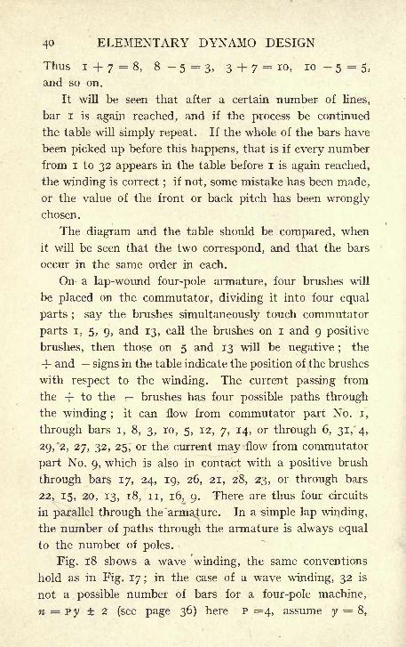
It will be seen that after a certain number of lines,
bar I is again reached, and if the process be continued
the table will simply repeat. If the whole of the bars have
been picked up before this happens, that is if every number
from i to 32 appears in the table before i is again reached,
the winding is correct;
if not, some mistake has been made,
or the value of the front or back pitch has been wrongly
chosen.
The diagram and the table should be compared, when
it will be seen that the two correspond, and that the bars
occur in the same order in each.
On a lap-wound four-pole armature, four brushes will
be placed on the commutator, dividing it into four equal
parts ; say the brushes simultaneously touch commutator
parts i, 5, 9, and 13, call the brushes on i and 9 positive
brushes, then those on 5 and 13 will be negative ;the
+ and signs in the table indicate the position of the brushes
with respect to the winding. The current passing from
the -f- to the brushes has four possible paths through
the winding ;it can flow from commutator part No. i,
through bars i, 8, 3, 10, 5, 12, 7, 14, or through 6, 31,' 4,
29/2, 27, 32, 25, or the current may flow from commutator
part No. 9, which is also in contact with a positive brush
through bars 17, 24, 19, 26, 21, 28, 23, or through bars
22, 15, 20, 13, 18, 11, 16, 9. There are thus four circuits
in parallel through the armature. In a simple lap winding,
the number of paths through the armature is always equal
to the number of poles.
Fig. 18 shows a wave winding, the same conventions
hold as in Fig. 17; in the case of a wave winding, 32 is
not a possible number of bars for a four-pole machine,
n = py 2 (see page 36) here P =4, assume y = 8,
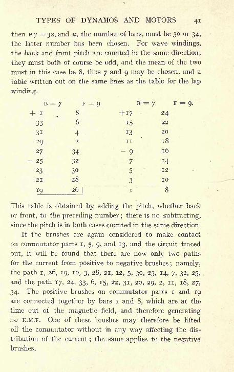
TYPES OF DYNAMOS AND MOTORS 41
then P y = 32, and n, the number of bars, must be 30 or 34,
the latter number has been chosen. For wave windings,
the back and front pitch are counted in the same direction,
they must both of course be odd, and the mean of the two
must in this case be 8, thus 7 and 9 may be chosen, and a
table written out on the same lines as the table for the lap
winding.
F = 9.
This table is obtained by adding the pitch, whether back
or front, to the preceding number;there is no subtracting,
since the pitch is in both cases counted in the same direction.
If the brushes are again considered to make contact
on commutator parts I, 5, 9, and 13, and the circuit traced
out, it will be found that there are now only two paths
for the current from positive to negative brushes; namely,
the path i, 26, 19, 10, 3, 28, 21, 12, 5, 30, 23, 14, 7, 32, 25,
and the path 17, 24, 33, 6, 15, 22, 31, 20, 29, 2, n, 18, 27,
34. The positive brushes on commutator parts i and 19
are connected together by bars i and 8, which are at the
time out of the magnetic field, and therefore generating
no E.M.F. One of these brushes may therefore be lifted
off the commutator without in any way affecting the dis-
tribution of the current;the same applies to the negative
brushes.
42 ELEMENTARY, DYNAMO DESIGN
In all simple wave windings, there are only two pathsin parallel through the armature, whatever the number of
poles, and the current may be collected at the commutator,
either at two points or at a number of points equal to the
number of poles. In the case of wave winding, the two
positive brushes or the two negative brushes, taking the
case of a four-pole machine, are electrically at the same
point of the armature winding ; although they are diamet-
rically opposite one another on the commutator, the seg-
ments with which they are in contact are connected together
by one armature coil only, and the bars of which this coil
consists are at the time in the middle of the space between
adjacent poles and are giving no E.M.F. The current
divides, therefore, between the two brushes in proportions
which are settled only by the contact resistance of the
brushes and the resistance of their connections to the
terminals. There is no positive force causing the current
to divide equally between the two brushes. This is found
in practice to be of little importance in small machines,
but in large machines it may become a very serious matter;
as one brush may take a large part or even the whole of
the current, it is consequently badly over-loaded, sparking
takes place, and the brush may get extremely hot.
In a lap winding, this difficulty does not occur;to pass
from one positive brush to the other, half the coils of the
armature must be passed through, and each brush has to
take its share of the current coming from the adjacent
quarters of the winding. The whole of the E.M.F. generated
in these coils compels the current to flow through the brush.
There is, therefore, in this case, no chance of the brushes
getting unequally loaded on account of their resistances
being different;
but one or other of the windings which
are put in parallel by the brushes may have generated in
it an E.M.F. slightly in excess of the other windings. This
TYPES OF DYNAMOS AND MOTORS 43
will cause it to take an excessive share of the current, and
this excessive current will pass from the commutator into
one set of brushes.
This can be remedied by the use of what are known
as equalising rings. Equalising rings consist of connec-
tions joining all those bars which are under, say a positive
brush, at' the same instant. The number of such con-
nections is not very material; every third or fourth bar
may be joined to all other bars at the same potential.
These connections keep the excess current from passing out
to the brush and spoiling the commutator and, further,
by giving a free path for the excess current generated,
they increase the armature reaction to such an extent as
greatly to modify, if not totally to do away with, the
uneven distribution of magnetic field which originally
caused too large an -E.M.F. to be generated in that part of
the winding. Thus the fault of too great a current in anyone part of the winding automatically corrects itself.
By varying the pitch at the front or back, various other
schemes of winding may be obtained, having the effect
of multiplying by 2, 3 or more the number of paths in
parallel. These, however, are seldom used;
on small
machines they are not required, and on those of larger size
they are found to lead to trouble at the commutator throughuneven distribution of the current in the different circuits.
A very full description of all different kinds of armature
windings will be found in Parshall and Hobart's" Arma-
ture Windings."
9. Magnet Winding's. The connections of the magnet
windings of a dynamo are a much simpler matter than the
armature windings. There are, however, several waysin which the magnet windings may be connected in circuit.
Figs. 20; 21, 22, and 23 illustrate these different methods,
In Fig. 20 the source of supply for the magnet winding
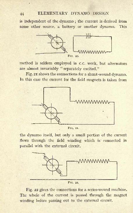
44 ELEMENTARY DYNAMO DESIGN
is independent of the dynamo ;the current is derived from
some other source, a battery or another dynamo. This
^VWWWWVWFIG. 20.
method is seldom employed in c.c. work, but alternators
are almost invariably"separately excited."
Fig. 21 shows the connections for a shunt-wound dynamo.In this case the current for the field magnets is taken from
-^AA/WWVWWV-n
FIG. 21.
the dynamo itself, but only a small portion of the current
flows through the field winding which is connected in
parallel with the external circuit.
I-x/VVWVWWW i
FIG. 22.
Fig. 22 gives the connections for a series-wound machine.
The whole of the current is passed through the magnet
winding before passing out to the external circuit.
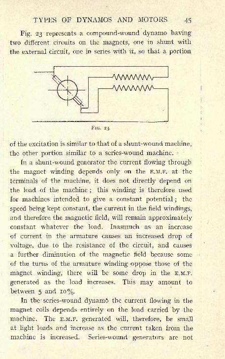
TYPES OF DYNAMOS AND MOTORS 45
Fig. 23 represents a compound-wound dynamo having
two different circuits on the magnets, one in shunt with
the external circuit, one in series with it, so that a portion
Vs/WWWViVVWWW
,
FIG. 23.
of the excitation is similar to that of a shunt-wound machine,
the other portion similar to a series-wound machine.
In a shunt-wound generator the current flowing through
the magnet winding depends only on the E.M.F. at the
terminals of the machine, it does not directly depend on
the load of the machine;
this winding is therefore used
for machines intended to give a constant potential ;the
speed being kept constant, the current in the field windings,
and therefore the magnetic field, will remain approximately
constant whatever the load. Inasmuch as an increase
of current in the armature causes an increased drop of
voltage, due to the resistance of the circuit, and causes
a further diminution of the magnetic field because some
of the turns of the armature winding 'Oppose those of the
magnet winding, there will be some drop in the E.M.F.
generated as the load increases. This may amount to
between 5 and 10%.In the- series-wound dynamo the current flowing in the
magnet coils depends entirely on the load carried by the
machine. The E.M.F. generated will, therefore, be small
at light loads and increase as the current taken from the
machine is increased. Series-wound generators are not
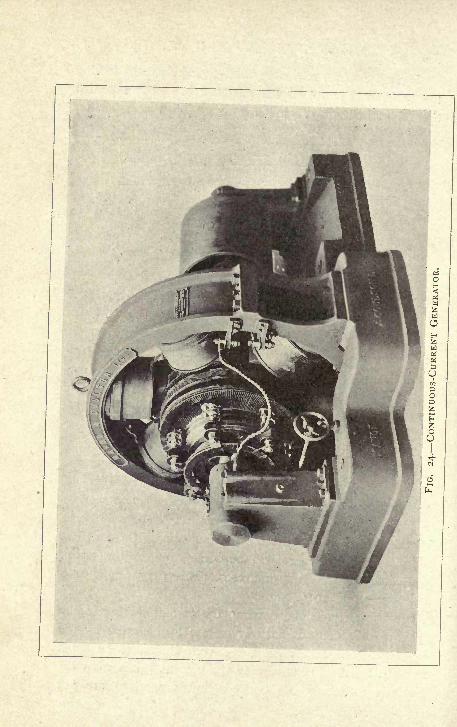
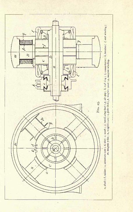
48 ELEMENTARY DYNAMO DESIGN
frequently used, but there are many cases where a series-
wound motor is found useful.
The compound - wound generator is used in all cases
where it is necessary that the E.M.F. should be kept constant
without hand regulation. Since series turns increase the
E.M.F. generated as the load increases, it is evident that
the addition of a few series turns will counteract the tendency
of the shunt-wound machine to drop its E.M.F. at high loads,
and a machine having the correct proportion of shunt and
series turns will give a constant E.M.F. whatever current is
being taken from it.
It is usual to use compound-wound generators in all
small installations, such as ship lighting and private house
lighting. In large central stations dealing with a lighting
load only, shunt-wound machines are usually put in to
save the extra complications at the switchboard;
the
regulation of the voltage is effected by hand, by intro-
ducing or cutting out resistance in the shunt circuit.
CHAPTER III
CONTINUOUS-CURRENT GENERATOR
1. Specification of Generator and Chief Dimensions.
In this chapter the calculations for the design of a con-
tinuous-current generator will be considered. The problem
may be put before the designer in various ways, but a
common form of occurrence is to require a generator of
a stated output at a given speed. The specification in
addition often demands a guaranteed temperature rise
after six, ten or even more hours' run at full load. There
is frequently specified in addition a given voltage regulation
with various loads.
Say that it is required to design a generator to give
200 amperes, 500 volts at 420 revolutions per minute, and
that the temperature is not to exceed 70 F. after a six
hours' run at full load.
Let it be decided in accordance with present practice
that the dynamo shall be a multipolar machine, with a
slotted drum armature and a developed end winding-
Fig. 24 giving the general arrangement of the machine,
which is shown with six poles. The considerations oh
which this number is determined will be dealt with later.
It is now required to find all the principal dimensions
of a machine to comply with the above requirements.
Unfortunately the conditions are too complicated to
allow of any simple formula being devised in which substi-
tution could give directly the desired result, and the process
of designing any electrical machinery becomes one of trial
and error. It is necessary to adopt tentatively Certain
E 49
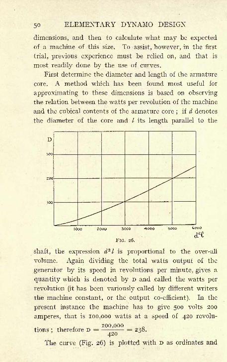
ELEMENTARY DYNAMO DESIGN
dimensions, and then to calculate what may be expected
of a machine of this size. To assist, however, in the first
trial, previous experience must be relied on, and that is
most readily done by the use of curves.
First determine the diameter and length of the armature
core. A method which has been found most useful for
approximating to these dimensions is based on observing
the relation between the watts per revolution of the machine
and the cubical contents of the armature core;
if d denotes
the diameter of the core and / its length parallel to the
D
boo
200
100
1000 200O 300O
FIG. 26.
shaft, the expression d 21 is proportional to the over-all
volume. Again dividing the total watts output of the
generator by its speed in revolutions per minute, gives a
quantity which is denoted by D and called the watts per
revolution (it has been variously called by different writers
the machine constant, or the output co-efficient). In the
present instance the machine has to give 500 volts 200
amperes, that is 100,000 watts at a speed of 420 revolu-
100,000tions ;
therefore D = = 238.
The curve (Fig. 26) is plotted with D as ordinates and
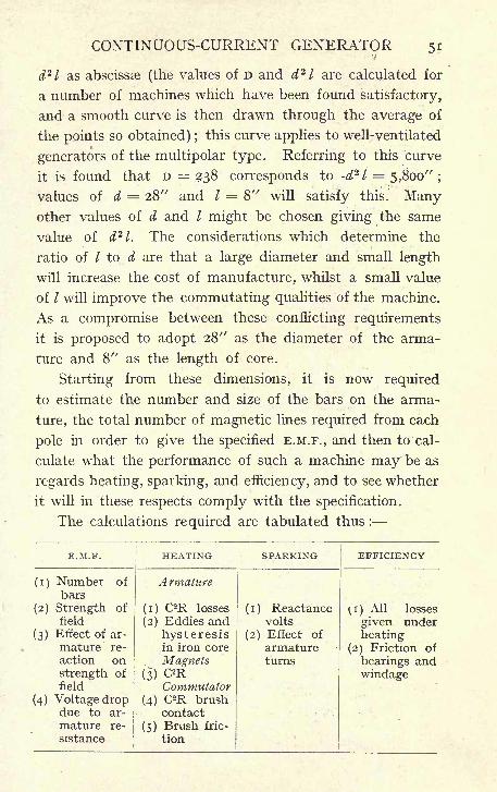
CONTINUOUS-CURRENT GENERATOR
d 2l as abscissae (the values of D and d 2
1 are calculated for
a number of machines which have been found satisfactory,
and a smooth curve is then drawn through the average of
the points so obtained) ;this curve applies to well-ventilated
generators of the multipolar type. Referring to this curve
it is found that D = 238 corresponds to -d 2l = 5,800" ;
values of d = 28" and / = 8" will satisfy this. Manyother values of d and I might be chosen giving the same
value of d 2l. The considerations which determine the
ratio of I to d are that a large diameter and small length
will increase the cost of manufacture, whilst a small value
of I will improve the commutating qualities of the machine.
As a compromise between these conflicting requirements
it is proposed to adopt 28" as the diameter of the arma-
ture and 8" as the length of core.
Starting from these dimensions, it is now required
to estimate the number and size of the bars on the arma-
ture, the total number of magnetic lines required from each
pole in order to give the specified E.M.F., and then to cal-
culate what the performance of such a machine may t>e as
regards heating, sparking, and efficiency, and to see whether
it will in these respects comply with the specification.
The calculations required are tabulated thus :
52 ELEMENTARY DYNAMO DESIGN
2. Number of Bars on Armature. Take first the
number of bars required on the armature. It is seen that
this will depend on the total flux from the magnet and on
the speed (see page 17). The speed is determined by the
specification. As to the total flux, a large ,total number
of magnetic lines per pole will mean powerful and ex-
pensive magnets, it will involve working at a high density
in the air gap, and this will require more copper on the
magnets and increase their cost. A high total flux will
also generally mean increased losses in the armature iron.
On the other hand, a high density in the gap is good
from the point of view of commutation, and the total flux
must be kept high so that the number of bars on the arma-
ture does not become excessive.
A common density to work at in the air gap is from
7,000 to 8,000 lines per square centimeter. The value of B
being fixed, the total flux will depend on the area of the
pole shoe.
It is usual to make the length of pole shoe, measured
parallel to the shaft, equal to the length of the armature
core. The pole shoe area will then be equal to the length
of armature core multiplied by the pole arc.
The distance from the centre of one pole to the centre
of the next being called the pole pitch, the ratio of the
pole arc to the pole pitch is a quantity to be carefully
considered;
if the pole arc is long and poles of opposite
polarity are therefore close together, the amount of leakage
will be greatly increased. On the other hand, too small
a pole arc will reduce the pole area and therefore the number
of useful lines. In a machine of this size a common ratio
is -7, in smaller machines it may fall as low as -6. If it
be agreed to adopt -7 as the ratio of pole arc to pole pitch
in this machine, the pole arc will have a length of 7
CONTINUOUS-CURRENT GENERATOR 53
X -7= 10 -2", 28 TT being the circumference of the armature
and r- the pole pitch. Multiplying io-2" by 8" the
length of armature core, 10-2 x 8 = 81-6 square inches
and 81-6 x 6-45 = 525 square centimeters is obtained
as the area of the pole face. But the magnetic lines from
the pole shoe will spread, and there is, therefore, a fringe
of magnetic lines beyond the actual area of the shoe. Take
this as 5%, and 550 square cms. is the actual area effective
for carrying line of force. Working at a density of 7,900
in the air gap this will give as the total number of lines
7,900 X 550 = 4350 5ooo.
It has been seen in Chapter I., 8, that the E.M.F.
generated in a conductor depends on the number of lines
cut by the conductor in unit time. If N be the total number
of lines of force from one pole of the magnet, and if there
be P poles P x N will be the total number of lines of force
cut by-one conductor on the armature during one revolution.
T?
Again if R be the number of revolutions per minute 7- = the
number of revolutions per second, the total number of lines
pof force cut in one second by one conductor will be p N -7-
\j\j
and the E.M.F. generated in each of the conductors will add
together provided these conductors are connected in series;if
therefore z represent the number of bars on the armature cori-
nected in series, the E.M.F. generated in the armature will be
RZP N z-.
60
This result gives the E.M.F. in C.G.S. units, and must be
divided by io 8 to express the E.M.F. in volts; if, "therefore,
E be the E.M.F. required, measured in volts,
z P N RE =
IO 8 X 60'
54 ELEMENTARY DYNAMO DESIGN
For the present purpose this can best be written in the
form
_ E X I0 8 X 60.
P X R
Substituting in this formula;
the E.M.F. required at the
terminals is 500, but at full load there will be a drop due
to the resistance of the armature (and of the series windingif the dynamo is compound wound). Assume this at 4%
500 x -04= 20
At full load, therefore, the armature must generate 520
volts, and E = 520, P = 6. N has been found to be 4,350,000
520 x io 8 x 60.-. z == 7
- = 284.6 x 4-35 x io 6 x 420
The armature can be wound "lap
"or
" wave "(see Chapter
II.) ; in the former case there will be six circuits from brush
to brush in the armature, in the latter two, and the total
number of bars will be 1,704 and 568 respectively. Wave
winding is preferable in this instance, 1,704 bars being an
excessive number, which would entail an expensive com-
mutator and undue waste of space in insulation;thus
568 is the total number of bars required on the armature.
The number of commutator parts in a machine of this
size will be half the number of bars, i.e., 284, and this
divided by the number of poles gives about 47 commu-
tator parts per pole. It is well in 500-volt machines to
aim at about 50 commutator parts per pole, so that in this
respect the number of bars is satisfactory.
3. Size of Armature Bars and their Disposal in the
Slots. The next question to consider is as to the size
of the bars and their arrangements in the slots. The size
of the bar depends ultimately on not losing an excessive
number of watts (c2
<w) in the armature winding, co being
the resistance of the armature winding from brush to brush.
As this, however, cannot be calculated at this stage, it
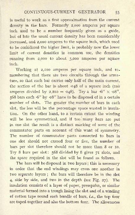
CONTINUOUS-CURRENT GENERATOR 55
is useful to work as a first approximation from the current
density in the bars. Formerly 2,000 amperes per square
inch used to be a number frequently given as a guide,
but of late the usual current density has been considerably
increased, and 2,000 amperes to the square inch, which used
to be considered the higher limit, is probably now the lower
limit of current densities in common use, the densities
running from 2,000 to about 3,000 amperes per square
inch.
Working at 2,100 amperes per square inch, and re-
membering that there are two circuits through the arma-
ture, so that each bar carries only half of the main current,
the section of the bar is about -048 of a square inch (100
amperes divided by 2,100 = -048). Try a bar -6" x -08",
568 bars each -6" by -08" have to be disposed of in a certain
number of slots. The greater the number of bars in each
slot, the less will be the percentage space wasted in insula-
tion. On the other hand, to a certain extent the windingwill be less symmetrical, and if too many bars are put
in one slot the result is a distinct marking of some of the
commutator parts on account of this want of symmetry.The number of commutator parts connected to bars in
one slot should not exceed four or five, the number of
bars per slot therefore should not be more than 8 or 10.
Try 8 bars per slot : 568 divided by 8 gives 71 slots, and
the space required in the slot will be found as follows.
The bars will be disposed in two layers ;this is necessary
in order that the end windings may cross one another in
two separate layers ;the bars will therefore be in the slot
4, side by side, and two in the depth (see Fig. 27). The
insulation consists of a layer of paper, presspahn, or similar
material formed into a trough lining the slot and of a windingof cotton tape round each bundle of bars, i.e., the top four
are taped together and also the bottom four. The allowances
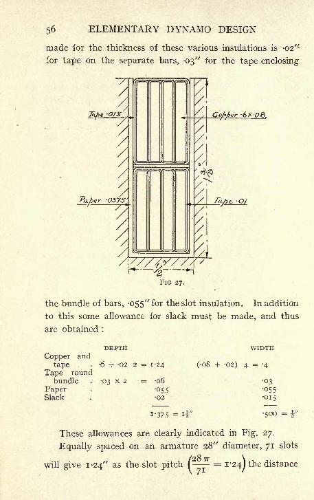
ELEMENTARY DYNAMO DESIGN
made ior the thickness of these various insulations is -02"
for tape on the separate bars, -03" for the tape enclosing
FIG 27.
the bundle of bars, -055" for the slot insulation. In addition
to this some allowance for slack must be made, and thus
are obtained :
DEPTH
Copper and
tape . -6 + -02 2 = 1-24
Tape roundbundle . -03 x 2 = -06
Paper'
,- -055Slack -02
WIDTH
(08 + -02) 4 = -4
03055015
500 =1-375 = if"
These allowances are clearly indicated in Fig. 27.
Equally spaced on an armature 28" diameter, 71 slots
will give I -24" as the slot pitch p-~=
*'24jthe distance
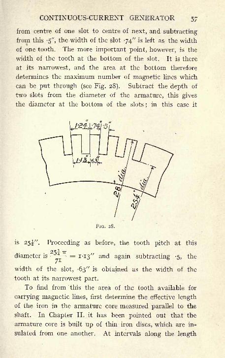
CONTINUOUS-CURRENT GENERATOR 57
from centre of one slot to centre of next, and subtracting
from this -5", the width of the slot 74" is left as the width
of one tooth. The more important point, however, is the
width of the tooth at the bottom of the slot. It is there
at its narrowest, and the area at the bottom therefore
determines the maximum number of magnetic lines which
can be put through (see Fig. 28). Subtract the depth of
two slots from the diameter of the armature, this gives
the diameter at the bottom of the slots;
in this case it
FIG. 28.
is 25J". Proceeding as before, the tooth pitch at this
^ -i- +7F-
diameter is4 = 1-13" and again subtracting -5, the
width of the slot, -63" is obtained as the width of the
tooth at its narrowest part.
To find from this the area of the tooth available for
carrying magnetic lines, first determine the effective length
of the iron in the armature core measured parallel to the
shaft. In Chapter II. it has been pointed out that the
armature core is built up of thin iron discs, which are in-
sulated from one another. At intervals along the length
58 ELEMENTARY DYNAMO DESIGN
of the armature, it is usual to put in distance pieces, thus
leaving ducts in the core, through which air is thrown out
for cooling purposes. The effective length of the armature
will therefore be the gross length less the width of these
ventilating ducts and less the space taken up by in-
sulation between the individual discs. It may be arranged
to put in three ventilating ducts each half an inch wide ;
this will give a total duct width of ij", which, subtracted
from 8" leaves 6J" of discs and insulation. The insulation
between discs is usually taken to amount to about 10%,
and the effective length of iron in armature 6-5 x -9= 5-8"
is thus found.
The number of teeth under one pole will be 71 divided
by 6 and multiplied by -7, the ratio of pole arc to pole
pitch, which is equal to 8-3. An allowance for the fringe
must, however, be made. Assume this fringe at 10%,
the number of teeth carrying the flux from one pole will
therefore be 8'3 x i'i = 9-1, and the area available at
the bottom of teeth will be 9-1 X 5-8 x -63 = 33-5
square inches. Multiply this by 6-45 to make it into
square centimeters, and divide the total number of lines
per pole, namely 4-350,000, by this area.
4,350,000 - = 20,000 lines per square centimeter.33
-
5 x *45
This is quite a safe value for the induction at the bottom
of the teeth. Good limiting values for this number are
20,000 to 22,000. The considerations which determine this
are that a high value gives what is known as a stiff field ;
that is, the iron of the teeth being strongly saturated, the
strength of field will not readily be affected by the armature
current; whilst, on the other hand, with a higher value of
tooth induction the number of ampere-turns required on
the magnets to overcome the reluctance of the highly
saturated iron rapidly becomes excessive.
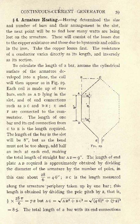
CONTINUOUS-CURRENT GENERATOR 59
4. Armature Heating1
. Having determined the size
and number of bars and their arrangement in the slot,
the next point will be to find how many watts are being
lost on the armature. These will consist of the losses due
to the copper resistance and those due to hysteresis and eddies
in the iron. Take the copper losses first. The resistance
of a conductor varies directly as its length, and inversely
as its section.
To calculate the length of a bar, assume the cylindrical
surface of the armature de-
veloped into a plane, the coil
will then appear as in Fig. 29.
Each coil is made up of two
bars, such as A D lying in the
slot, and of end connections
such as B c and D E;
E and
F are connected to the com-
mutator. The length of one
bar and its end connection from
c to E is the length required.
The length of the bar in the slot
will be 8", but as the bend
must not be too sharp, add half
an inch at each end, makingthe total length of straight bar A D = 9"'. The length of end
plate A B required is approximately obtained by dividing
the diameter of the armature by the number of poles, in
this case about -?- 4-6" ;B c is the length measured
along the armature periphery taken up by one bar ;this
length is obtained by dividing the pole pitch by 2, that is,
287T
FIG. 29.
= 8-5. The total length of a bar with its end connections
60 ELEMENTARY DYNAMO DESIGN
will therefore beDB + AC-fDE-f allowance for bend at c,
say, 9" + 8i" + 8V + 2" = 28";but there are 568 such
bars, and the total length of copper will therefore be
28568 x = 1,300 feet.
The resistance of the copper can be found either from
the known resistance of a cubic inch, or, as is perhapsmore convenient in practice, from a table, giving the resist-
ance per foot of different sections. A sample of such a
table is given in the Appendix. From such a table, the
section being -6 by -08, the resistance is found to be
00019 ohm per foot, and therefore -246 ohm for 1,300
feet. This resistance includes 12% for the increased resist-
ance due to the heating of the armature. In proceeding
to calculate the watts lost, it must be remembered that
there are two paths through the winding which are con-
nected in parallel by the brushes, and that therefore the
resistance obtained for the whole length of winding must
be divided by 4 to give the resistance from brush to brush.
The c 2 w losses are therefore
- = -0615 ohm resistance from brush to brush,
0615 X 200 = 12-3 volts dropped,
12-3 X 200 = 2460 watts lost.
The losses in the iron are usually found by working out
the losses per pound and multiplying by the total weight.
These losses depend upon the induction, that is the number
of lines per square centimeter, and also on the frequency.
It can be shown quite readily that the eddy losses vary
as the square of the periodicity and as the square of the
induction. The hysteresis losses vary directly as the
periodicity ; they increase with, but more rapidly than,
the induction, and are usually assumed to vary as B 1'
6.
From this it follows that as the induction in different parts

CONTINUOUS-CURRENT GENERATOR 6r
of the circuit will be different, being for instance much
higher at the bottom of the tooth than in the body of the
core, these different parts should really be separated and
calculated each by itself. In practice, however, it is found
sufficiently accurate to work from a curve giving the rela-
tion between periodicity multiplied by B and watts lost
per pound. Such a curve is given below (Fig. 30). The
induction B in the
core, and the number
of reversals perseconds ascertained,
these numbers are
multiplied together,
and from the curve
the corresponding
number of watts lost
per pound of iron is
read off.
In order to make
some allowance for
350
300
250
50
5 I'O 1-5 2-O 25 3-0 3-ff 4-O
Ufattofxxjil
the higher indue- FIG. 30.
tions in the teeth, it
is usual to calculate the weight of the core as if there
were no slots. The small extra weight thus gained makes
some allowance in the calculation for the fact that the
losses in the teeth will be greater than calculated on.
The curve is based on the assumption that the induc-
tion in the core does not differ very greatly from 10,000
lines per square centimeter.
Now must be calculated the depth for the core discs,
giving the diameter of the hole in the centre of the discs.
The effective length of iron has already been found to be
5-8", and in order to work at about 10,000 lines per squarecentimeter in the armature core the sectional area must be
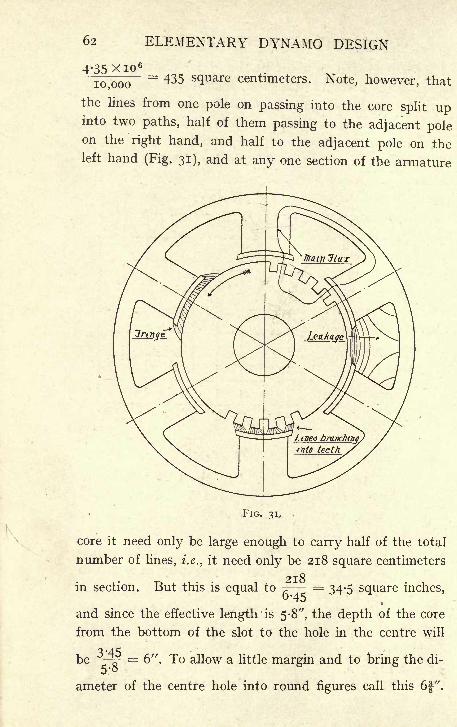
62 ELEMENTARY DYNAMO DESIGN
4-35 xio 6"
I0,ooo= 435 S(lliare centimeters. Note, however, that
the lines from one pole on passing into the core split upinto two paths, half of them passing to the adjacent poleon the right hand, and half to the adjacent pole on theleft hand (Fig. 31), and at any one section of the armature
FIG. 31, .
core it need only be large enough to carry half of the total
number of lines, i.e., it need only be 218 square centimeters
in section. But this is equal to^
= 34-5 square inches,
and since the effective length is 5-8", the depth of the core
from the bottom of the slot to the hole in the centre will
be *MjP= 6". To allow a little margin and to bring the di-
ameter of the centre hole into round figures call this 6f".
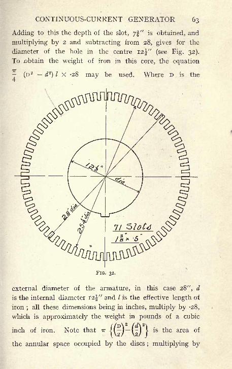
CONTINUOUS-CURRENT GENERATOR 63
Adding to this the depth of the slot, 7!" is obtained, and
multiplying by 2 and subtracting from 28, gives for the
diameter of the hole in the centre I2j" (see Fig. 32).
To .obtain the weight of iron in this core, the equation
;(- / X -28 may be used. Where D is the
FIG. 32.
external diameter of the armature, in this case 28", d
is the internal diameter 12%" and / is the effective length of
iron;
all these dimensions being in inches, multiply by -28,
which is approximately the weight in pounds of a cubic
inch of iron. Note that TTj(~y (~)
[*s tne area *
the annular space occupied by the discs ; multiplying by
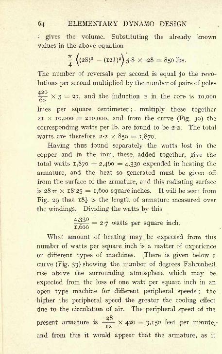
64 ELEMENTARY DYNAMO DESIGN
* gives the volume. Substituting the already known
values in the above equation
7T
4
The number of reversals per second is equal Jo the revo-
lutions per second multiplied by the number of pairs of poles
-((28)
2 -(I2l)
2
)5-8 X -28 m 850 Ibs.
- x 3 = 21, and the induction B in the core is 10,000
lines per square centimeter; multiply these together
21 X 10,000 = 210,000, and from the curve (Fig. 30) the
corresponding watts per Ib. are found to be 2-2. The total
watts are therefore 2-2 X 850 = 1,870.
Having thus found separately the watts lost in the
copper and in the iron, these, added together, give the
total watts 1,870 + 2,460 = 4,330 expended in heating the
armature, and the heat so generated must be given off
from the surface of the armature, and this radiating surface
is 28 TT x 18*25 = i ,600 square inches. It will be seen from
Fig. 29 that i8J is the length of armature measured over
the windings. Dividing the watts by this
j~
= 27 watts per square inch.
What amount of heating may be expected from this
number of watts per square inch is a matter of experience
on different types of machines. There is given below a
curve (Fig. 33) showing the number of degrees Fahrenheit
rise above the surrounding atmosphere which may be
expected from the loss of one watt per square inch in an
open type machine for different peripheral speeds ; the
higher the peripheral speed the greater the cooling effect
due to the circulation of air. The peripheral speed of the
28present armature is - X 420 = 3,150 feet per minute,-
and from this it would appear that the armature, as it
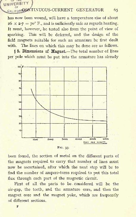
UNIVERSITYGENERATOR 65
has now been wound, will have a temperature rise of about
26 X 27 = 70 F., and is sufficiently safe as regards heating.
It must, however, be tested also from the point of view of
sparking. This will be deferred, and the design of the
field magnets suitable for such an armature be first dealt
with. The lines on which this may be done are as follows.
5. Dimensions of Magnet. The total number of lines
per pole which must be put into the armature has already
been found, the section of metal on the different parts of
the magnets required to carry that number of lines must
now be ascertained, after which the next step will be to
find the number of ampere-turns required to put this total
flux through each part of the magnetic circuit.
First of all the parts to be considered will be the
air-gap, the teeth, and the armature core, and then the
magnet core and the magnet yoke, which are frequently
of different sections.
66 ELEMENTARY DYNAMO DESIGN
Magnets are now usually made of cast steel. The
permeability does not differ materially from that of wroughtiron. The material, however, is somewhat less trustworthy ;
the permeability in different specimens varies largely,
and it is therefore not safe to work at a very high induc-
tion; B = 13,000 to 13,500 per square centimeter is a safe
value to take. It must also be noted that higher values
of the induction mean a greater number of ampere-turnson the magnets, and this, as will be seen, means increased
weight of copper, so that the saving in steel effected by
reducing the section is lost in the increased cost of copper
required on the magnets.
The total number of lines per pole is 4,350,000, but
this number represents the useful lines which actually
cut the armature conductors, and there will be in addition
to this a certain number of lines passing through the magnet
coil, and therefore through the steel of the magnet core,
which "leak
"through various paths, and do not enter
the armature. This leakage is clearly shown in Fig. 31,
and to allow for it the number of useful lines is multiplied
by a"leakage coefficient." A safe value to take in such
a machine as we are considering is 1-2. The total number
of lines passing through the magnet core and yoke will
then be 4,350,000 X 1-2 .= 5,200,000, and in order to
work at a density of 13,000 lines per square centimeter,
the area of the pole will have to be
5,200,000 = square cms.; ^5 = 5I<5 Square inches.
6-45
A good section for the magnet cores is to make them
circular ;for a given area this gives the smallest length
of periphery, and thus shortens the length of copper wire
required for the winding. If the magnet cores be made
8f-" diameter, this gives a sectional area of 61-5 square
inches. The area of the ring carrying the magnet cores
CONTINUOUS-CURRENT GENERATOR 67
must also be 6l square inches or thereabouts;
but here
again, as in the case of the armature core, the lines from one
pole have two paths through the ring, and since half of them
only pass through any given section, the section can there-
fore be reduced to 30-5 square inches. Fig. 31 shows the
magnetic circuit of the machine and the approximate paths
of the lines of magnetic induction. At this stage it is
advisable to make such a drawing to a fairly large scale..
The length of the magnet core is determined by the
space required for the magnet winding ;in this case 7"
will be enough between the flanges ;i" for the pole
shoe, and about i" to allow for the curvature of the ring
(Fig. 36), giving a total length from the face of the pole
shoe to the inside of the magnet ring of 9". The depth of
air gap, that is the distance from the top of the teeth to the
pole face, has been taken at J". The greater this dimension,
the greater will be the number of ampere-turns required to
get the magnetic flux through the air space ;on the other
hand, enough space must be left for mechanical clearance,
and also to insure that the armature ampere-turns shall
not be too powerful in comparison to the magnet turns.
6. Calculation of Ampere - turns required on the
Magnets. A table is given below showing the calculation
of the ampere-turns required on each part of the magneticcircuit.
The first column gives the area in square centimeters
the second column gives the magnetic induction B, which is
in each case obtained by dividing 4,350,000, the numberof lines per pole, by the sectional area given in column I.
Column 3 is the value of H corresponding to B; in the
case of air H; is numerically equal to B;in the case of iron
or steel it is obtained from the magnetisation curves givenin Fig. 5. Column 4 gives the length in centimeters of the
path of magnetic lines ; where not already ascertained
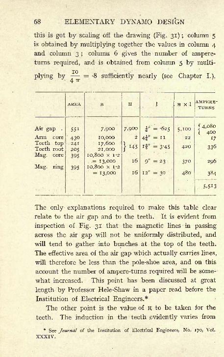
68 ELEMENTARY DYNAMO DESIGN
this is got by scaling off the drawing (Fig. 31) ; column 5
is obtained by multiplying together the values in column 4
and column 3 ;column 6 gives the number of ampere-
turns required, and is obtained from column 5 by multi-
! -UI0
plying by 8 sufficiently nearly (see Chapter I.).
The only explanations required to make this table clear
relate to the air gap and to the teeth. It is evident from
inspection of Fig. 31 that the magnetic lines in passing
across the air gap will not be uniformly distributed, and
will tend to gather into bunches at the top of the teeth.
The effective area of the air gap which actually carries lines,
will therefore be less than the pole-shoe area, and on this
account the number of ampere-turns required will be some-
what increased; This point has been discussed at great
length by Professor Hele-Shaw in a paper read before the
Institution of Electrical Engineers.*
The other point is the value of H to be taken for the
teeth. The induction in the teeth evidently varies from
* See Journal of the Institution of Electrical Engineers, No. 170, Vol.
XXXIV."
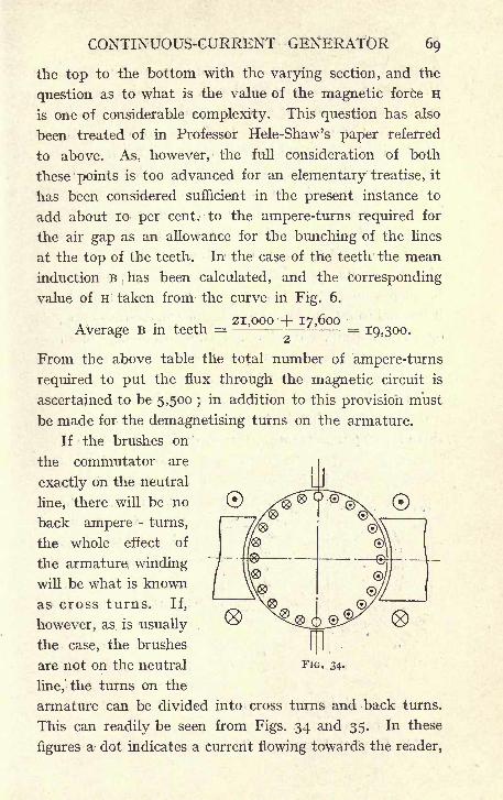
CONTINUOUS-CURRENT GENERATOR 69
the top to the bottom with the varying section, and the
question as to what is the value of the magnetic force H
is one of considerable complexity. This question has also
been treated of in Professor Hele-Shaw's paper referred
to above. As, however, the full consideration of both
these points is too advanced for an elementary treatise, it
has been considered sufficient in the present instance to
add about 10 per cent, to the ampere-turns required for
the air gap as an allowance for the bunching of the lines
at the top of the teeth. In the case of the teeth the mean
induction B has been calculated, and the corresponding
value of H taken from the curve in Fig. 6.
21,000 -f 17,600Average B in teeth = - - =
19,300.
From the above table the total number of ampere-turns
required to put the flux through the magnetic circuit is
ascertained to be 5,500 ; in addition to this provision must
be made for the demagnetising turns on the armature.
If the brushes on
the commutator are
exactly on the neutral
line, there will be no
back ampere - turns,
the whole effect of
the armature winding
will be what is known
as cross turns. If,
however, as is usually .
the case, the brushes
are not on the neutral
line,' the turns on the
armature can be divided into cross turns and back turns.
This can readily be seen from Figs. 34 and 35. In these
figures a dot indicates a current flowing towards the reader,
FIG. 34.
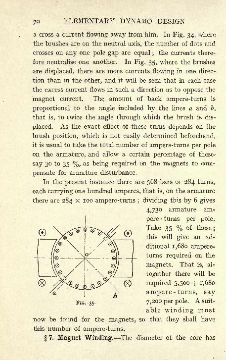
ELEMENTARY DYNAMO DESIGN
a cross a current flowing away from him. In Fig. 34, where
the brushes are on the neutral axis, the number of dots and
crosses on any one pole gap are equal ; the currents there-
fore neutralise one another. In Fig. 35, where the brushes
are displaced, there are more currents flowing in one direc-
tion than in the other, and it will be seen that in each case
the excess current flows in such a direction as to oppose the
magnet current. The amount of back ampere-turns is
proportional to the angle included by the lines a and b,
that is, to twice the angle through which the brush is dis-
placed. As the exact effect of these turns depends on the
brush position, which is not easily determined beforehand,
it is usual to take the total number of ampere-turns per pole
on the armature, and allow a certain percentage of these*
say 30 to 35 %, as being required on the magnets to com-
pensate for armature disturbance.
In the present instance there are 568 bars or 284 turns,
each carrying one hundred amperes, that is, on the armature
there are 284 X 100 ampere-turns ; dividing this by 6 gives
4,730 armature am-
pere-turns per pole.
Take 35 % of these;
this will give an ad-
ditional i,680 ampere-
turns required on the
magnets. That is, al-
together there will be
required 5,500 + 1,680
ampere-turns, say
7,200 per pole. A suit-
able winding must
now be found for the magnets, so that they shall have
this number of ampere-turns.
7. Magnet Winding. The diameter of the core has
FIG. 35.
CONTINUOUS-CURRENT GENERATOR 71
been found to be 8";insulation will have to be provided
between the steel of the magnet and copper winding. In
a machine of this size it is usual to put the winding not
directly on to the core, but on a former which must be of
dimensions suitable for slipping on to the core, taking
into account possible inequalities of the casting. This
former is sometimes made of sheet iron, in which case it
is necessary to allow for a layer of paper, cloth, or other
insulating medium before the wire is put on;
in other
cases the former is made of some insulating substance in
the nature of papier mache, or one of the many similar
substances on the market.
In the latter case the dimensions of the former can be
worked from directly. In order to slip over a magnet core
8f"
in diameter, the inside of the former should be not less
than about 9", and allowing -J-" for the insulating material,
whether that be the former itself or a separate layer of
insulation, this gives the total of gj" as the diameter on
which wire has to be wound. The length of the winding
space required will not be far off 7" in this machine. If
it be made shorter, the depth of winding must be increased
in order to get in a sufficient quantity of copper, and it
is advisable that the depth of winding should not become
too great, as the heat is then retained and the cooling
is much less satisfactory.
Suppose that 7" be tried as the length between the
cheeks of the former, and as a first assumption let it be
assumed that 2" is the depth of copper wire which will
be required. The length of the mean turn will then be
obtained as follows. The shortest turn is wound, as has
been seen, on a diameter of gj-". The outer turn will have
a diameter of gj" plus twice 2", that is I3J". The mean
turn, that is the turn having the average length, will then
be wound on a diameter of Ilj-", since this is the mean
72 ELEMENTARY DYNAMO DESIGN
between 9^" and I3J-", and the length of the mean turn
will thus be nj X TT, which equals 35 $".
The next thing is to ascertain how many watts maybe got rid of in such a winding. If the cylindrical surface
of the coil be calculated on as being the only cooling
surface, it may reasonably be expected to get rid of
about -7 to -8 watt per square inch of this surface. The
outside turn will be wound on a diameter of 133-" and
the circumference of the coil on the outside will there-
fore be 13^ X TT = 42", and the length between the cheeks
will be 7". The area of the cylindrical surface is there-
fore 42 X 7 = 294 square inches, and it being expected to
radiate -72 watt from each square inch, the total watts
which may be lost in one coil will work out at 294 x *72
= 210 or 1,260 on the six coils.
The E.M.F. of the machine is 500 volts, and therefore
there will be on each coil, the six magnet coils being*' * * 'ioo
connected in series, an E.M.F. of 7- = 83 volts. To give
a margin allowing of the use of a shunt resistance, take
20% off this, and take 65 volts as the E.M.F. on each
coil. The current is then obtained by dividing the watts
2IOlost by the E.M.F.
-^-= 3-3 amperes, and the number of
turns of wire required is obtained by dividing the ampere-*7 20O
turns required by the current' =
2,170. There are,*!' 3 3
therefore required 2,170 turns of wire on each coil, and
since the length of the mean turn is 35-5" the length of wire
will be-
35-5 x,i7oft>
, , .. .. ,.;,
Again, if the E.M.F. on each coil is 65 volts, and the
current is to be 3-3 amperes, the resistance must be
CONTINUOUS-CURRENT GENERATOR 73
A = iq.8 ohms. It is therefore required to find a suit-3-3
able wire, so that the resistance of 6,440 ft. shall be 19-8
ohms. This can be got most easily from some of the many
published tables of the properties of copper wire. (See
sample table in Appendix.) Find in such a table a size
of wire the resistance of which isg^
= -0031 ohm per ft.
Number 16 S.W.G. comes very near this requirement, the
resistance being -003 ohm per ft.
Notice that in the case of a shunt winding, the size of
the wire alone determines the number of ampere-turns.
This is on the assumption that the length of mean turn
remains unaltered, and is evident on the following con-
sideration. If, having wound the coil with a certain number
of turns, this number is now doubled the resistance is
also doubled, and therefore half the current will flow in
the coil. The result of doubling the turns is therefore to
have half the current flowing through twice the number
of turns, leaving the ampere-turns unaltered. The gaugeof wire used in shunt winding, therefore, practically deter-
mines the number of ampere-turns, and the nurnber of turns
of such a wire which must be used is determined simply
by the number of watts which may be lost. That is to
say, the heating of the coil depends on the number of turns
which are put on;the ampere-turns depend on the size
of wire used.
On further reference to the copper table it is found
that the diameter of No, 16 copper wire is -064". The
wire will be double cotton-covered, and the thickness of
this covering may be taken as giving an increase of -012"
in the over-all diameter. The diameter over the insulation
will therefore be -076", and the length between the flanges
of the former has been taken as 7". The number of turns
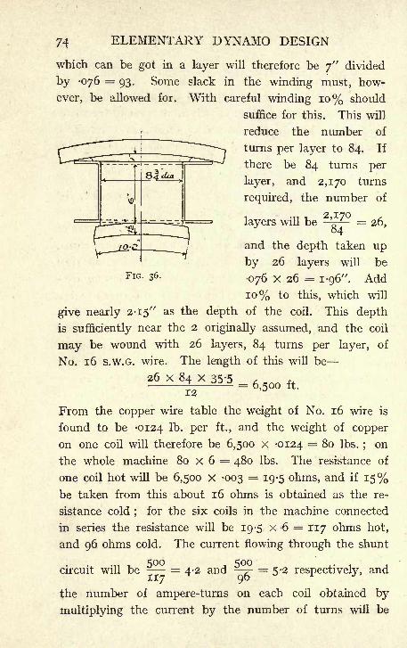
74 ELEMENTARY DYNAMO DESIGN
which can be got in a layer will therefore be 7" divided
by -076 = 93. Some slack in the winding must, how-
ever, be allowed for. With careful winding 10% should
suffice for this. This will
reduce the number of
turns per layer to 84. If
there be 84 turns per
layer, and 2,170 turns
required, the number of
layers will be '' = 26,84
and the depth taken up
by 26 layers will be
076 x 26 = 1-96". Add
10% to this, which will
give nearly 2-15" as the depth of the coil. This depth
is sufficiently near the 2 originally assumed, and the coil
may be wound with 26 layers, 84 turns per layer, of
No. 16 S.W.G. wire. The length of this will be
26 X 84 X 35-5
FIG. 36.
12- 6,500 ft.
From the copper wire table the weight of No. 16 wire is
found to be -0124 lb Per ft., and the weight of copper
on one coil will therefore be 6,500 x -0124 = 80 Ibs.;on
the whole machine 80 X 6 = 480 Ibs. The resistance of
one coil hot will be 6,500 x -003 = 19-5 ohms, and if 15%be taken from this about 16 ohms is obtained as the re-
sistance cold ;for the six coils in the machine connected
in series the resistance will be 19-5 X 6 = 117 ohms hot,
and 96 ohms cold. The current flowing through the shunt
circuit will be - = 4-2 and ~r- = 5-2 respectively, and
the number of ampere-turns on each coil obtained by
multiplying the current by the number of turns will be
CONTINUOUS-CURRENT GENERATOR 75
2,170 X 4-2 = 9,000 ; this allows of ample margin over
the 7,200 ampere-turns we calculated as being necessary,
and a shunt-regulating resistance connected in series with
the magnet winding will allow for regulation of the voltage
and also compensate for the extra current which flows
through the windings when they are cold and their resist-
ance is therefore lower than calculated.
If it be required that the machine should not be shunt
wound, but compound wound, it is necessary to distinguish
in working out the number of ampere-turns between the
ampere-turns required at no load and those required at
full load. This can be done by calculating again the value
of N, noting that at no load there is no drop in the armature,
and that the value to be substituted in the E.M.F. formula
is therefore in this case 500 instead of 520. Then again
work out the table of inductions and corresponding ampere-
turns for this new value of N;
at no load there is of course
no armature reaction. Proceeding on these lines it will
be found that the ampere-turns required at no load are
4,900.
Proceed in exactly the same way as above to find a
wire which will give 4,900 ampere-turns for the shunt
winding. The extra 2,300 ampere-turns must be provided
for by the series winding. The total current of the machine
at full load is 200 amperes ;in order that this should give
2,300 ampere-turns per coil, there must be on each coil
n turns. The easiest way of finding the section of copper
required is to start from the current density. The current
density on a machine of this size is usually from 800 to
1,000 amperes per square inch. Assuming 900, a section
of -22 square inch will be required. Wind with copper
i" by -22", the length of this copper per coil will be
= 34 ft., and allowing for the length required for connection
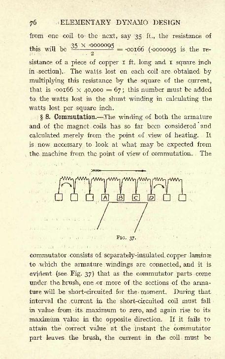
76 ELEMENTARY DYNAMO DESIGN
from one coil to the next, say 35 ft., the resistance of
35 x -0000005this will be - - = -00166 (-0000095 is the re-
sistance of a piece of copper I ft. long and I square inch
in -section). The watts lost on each coil are obtained by
multiplying this resistance by the square of the current,
that is -00166 x 40,000 = 67 ; this number must be added
to, the watts lost in the shunt winding in calculating the
watts lost per square inch.
8. Commutation. The winding of both the armature
and of the magnet coils has so far been considered and
calculated merely from the point of view of heating. It
is now necessary to look at what may be expected from
the machine from the point of view of commutation. The
FIG. 37.
.'.'.. .'I* 1 ' '- ! <*_ I I *
*
commutator consists of separately-insulated copper laminae
to which the armature windings are connected, and it is
evident (see Fig. 37) that as the commutator parts come
under the brush, one or more of the sections of the arma-
ture will be short-circuited for the moment. During that
interval the current in the short-circuited coil must fall
in value from its maximum to zero, and again rise to its
maximum value in the opposite direction. If it fails to
attain the correct value at the instant the commutator
part leaves the brush, the current in the coil must be
CONTINUOUS-CURRENT GENERATOR 77
forcibly brought to this value by the mechanical action
of the brush, and it is this which causes sparking. i
From the figure again, it can be seen that as the com-
mutator parts approach the brush, the coils as shown
on the left-hand side of the diagram have the current cir^
culating round in a clockwise direction. As they pass
the brush the coil is momentarily short-circuited, it then
leaves the brush, and passes into the right-hand half of the
figure, where the current is circulating round the coils in
a counter-clockwise direction. If the current has approx-
imately accomplished this reversal before leaving the brush,
the commutation is good, but, if it has failed to do so,
the current must suddenly be brought to the right value,
and this will be accompanied with sparking more or less
violent as the reversal has been less or more nearly accom-
plished. It is therefore most important to consider what
is happening during the period of short circuit.
If there were no self-induction in the .coil, that is, if
there were no tendency for the current to 'keep on flowing
in the same direction, it is evident that the mechanical
action of the brush would in itself be sufficient to give
the current its proper value. The changing contact resist-
ance between the brush and the commutator segments would
cause more of the current to flow into the segment A (see Fig.
37), as the surface of contact between this segment and
the brush increases, whilst the opposite effect would occur
in segment D, which is leaving the brush, so that as the
contact surface between these diminishes the resistance
would gradually increase, and less of the current would
therefore flow through commutator segment D, the current
which was flowing through this segment being gradually
diverted through the coil D c, and flowing into the brush
through segment c, thus gradually changing the direction
of the current through coil CD, so as to bring it into the
78 ELEMENTARY DYNAMO DESIGN
same direction as that in the armature coils on the right
of the figure.
However, the E.M.F. due to self-induction must be con-
sidered. The tendency of this is always to oppose any
change in the value of the current, and it will therefore have
the effect of making the reversal incomplete by the time the
segment is ready to leave the brush.
This E.M.F. of self-induction may be compensated for bythe E.M.F. due to the motion of the armature conductors
through the main magnetic field. In the case of a gener-
ator the field magnet which the conductors have just left
is of such a polarity as to give an E.M.F. in the same
direction as the current flowing before the short circuit.
It is therefore under the other pole, that which the bars are
approaching, that a suitable field must be looked for to assist
in reversing the current. Unfortunately, this is the pole
tip which is weakened by the cross turns on the armature,
and therefore only a comparatively weak reversing action
is obtained ;whilst the fact of having to move the brush
forward in order to find such a field is harmful by increasing
the number of back ampere-turns on the armature (see
6, page 70).
When copper brushes were the only ones in use, these
considerations were of great importance. It was always
necessary to move the brushes with change of load in
order to find a sparkless position. Now, however, carbon
brushes are invariably used, and it is quite usual to
specify that they shall run sparklessly with any load
and without change of position. This is possible partly
because the carbon brush, having a much greater contact
resistance with the copper segments of the commutator,
has an increased effect in reversing the current, but also
to a great extent because the sparking between the carbon
and copper is not nearly so detrimental as that between
CONTINUOUS-CURRENT GENERATOR 79
copper and copper, and that therefore a slight amount of
sparking, which is practically invisible, may take place with
a carbon brush without any injurious result, whilst the same
amount occurring on a copper brush would spoil the com-
mutator surface, which would have the effect of causing
the sparking to become more and more violent. In spite
of these advantages of the carbon brush, it is necessary,
in order to secure sparkless running with fixed brush
position, to take special precautions to keep the self-in-
duction of the armature coil as low as possible, since the
possibility of counteracting it by means of a suitable
value of the main field is excluded by the specified fixed
position of the brush.
The effect of the self-induction of the short-circuited
coil is estimated by calculating the reactance voltage of
the coil, that is the E.M.F. generated in the coil by varia-
tions in the magnetic flux due to the current in the coil
itself. For a fuller explanation of reactance voltage, see
Chapter VII.
The reactance voltage as calculated by the formulae
given below should, if possible, be under two volts if the
dynamo is to run at all loads with a fixed brush position.
In the larger machines it is impossible to obtain so low a
value except by using very abnormal dimensions for the
armature core and, provided care is taken that the other
constants of the machine are suitable, it is quite possible
to obtain satisfactory designs in which the value of the
reactance voltage is considerably greater than two volts.
The safest course, however, is always to keep the reactance
voltage as low as practicable.
The formula for calculating the reactance voltage was
first published in Parshall and Hobart's book on DynamoDesign ; they calculate the E.M.F. due to the self-in-
duction of the short-circuited turn on the assumption
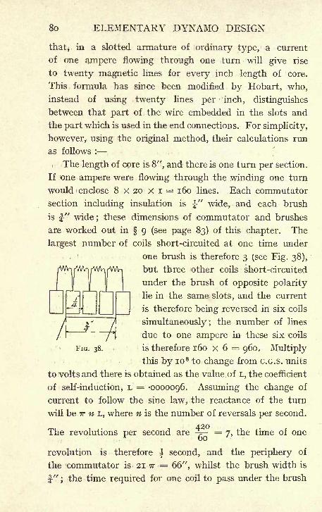
80 ELEMENTARY DYNAMO DESIGN
that, in a slotted armature of ordinary type, a current
of one ampere flowing through one turn will give rise
to twenty magnetic lines for every inch length of core.
This formula has since been modified by Hobart, who,
instead of using twenty lines per inch, distinguishes
between that part of the wire embedded in the slots and
the part which is used in the end connections. For simplicity,
however, using the original method, their calculations run
as follows :
The length of core is 8", and there is one turn per section.
If one ampere were flowing through the winding one turn
would enclose 8 x 20 x i = 160 lines. Each commutator
section including insulation is J-" wide, and each brush
is"wide; these dimensions of commutator and brushes
are worked out in 9 (see page 83) of this chapter. The
largest number of coils short-circuited at one time under
one brush is therefore 3 (see Fig. 38),
but three other coils short-circuited
under the brush of opposite polarity
lie in the same slots, and the current
is therefore being reversed in six coils
simultaneously; the number of lines
due to one ampere in these six coils
FIG. 38. is therefore 160 X 6 = 960. Multiply
this by io 8 to change from C.G.S. units
to volts and there is obtained as the value. of L, the coefficient
of self-induction, L = -0000096. Assuming the change of
current to follow the sine law, the reactance of the turn
will be TT n L, where n is the number of reversals per second.
The revolutions per second are - =7, the time of one
revolution is therefore| second, and the periphery of
the commutator is- 21 TT = 66", whilst the brush width is
f" ; the time required for one coil to pass under the brush
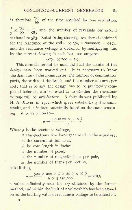
CONTINUOUS-CURRENT GENERATOR Si
'75is therefore -^
of the time required for one revolution,
I *75 I- X -4^-
=Q-. and the number of reversals per second
7 6 583
is therefore 583. Substituting these figures, there is obtained
for the reactance of the coil TT X 583 X '0000096 = -0174,
and the reactance voltage is obtained by multiplying this
by the current flowing in each bar, 100 amperes
0174 x 100 = 1-7.
This formula cannot be used until all the details of the
design have been worked out. It is necessary to know
the diameter of the commutator, the number of commutator
parts, the width of the brush, and the number of turns per
coil ;that is to say, the design has to be practically com-
pleted before it can be tested as to whether the reactance
voltage will be satisfactory. A formula was published byH. A. Mavor, in 1902, which gives substantially the same
results, and is in fact practically based on the same reason-
ing. It is as follows :
_ E cm 20 X TT X I
P P N
Where p is the reactance voltage,
E the electromotive force generated in the armature,
c the current at full load,
I the core length in inches,
p the number of poles,
N the number of magnetic lines per pole,
m the number of turns per section,
substituting
_ 500 X 200 XIX20X7rX8_P 6 x 4,350,000
a value sufficiently near the 1-7 obtained by the former
method, and within the limit of 2 volts which has been agreed
on as the limiting value of reactance voltage to be aimed at.
G
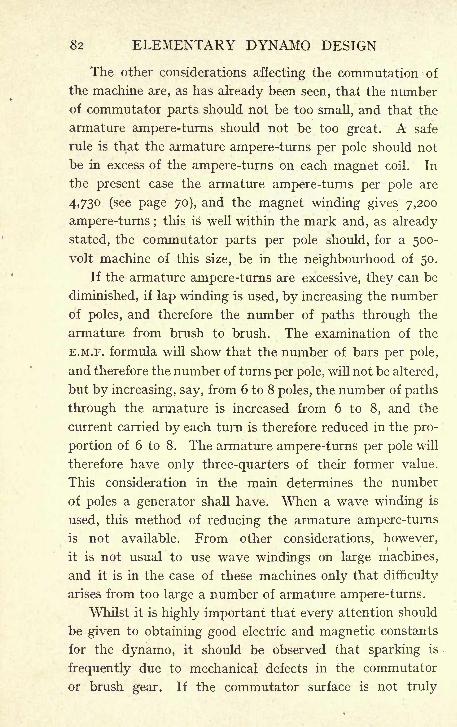
82 ELEMENTARY DYNAMO DESIGN
The other considerations affecting the commutation of
the machine are, as has already been seen, that the numberof commutator parts should not be too small, and that the
armature ampere-turns should not be too great. A safe
rule is that the armature ampere-turns per pole should not
be in excess of the ampere-turns on each magnet coil. In
the present case the armature ampere-turns per pole are
4,730 (see page 70), and the magnet winding gives 7,200
ampere-turns ;this is well within the mark and, as already
stated, the commutator parts per pole should, for a 500-
volt machine of this size, be in the neighbourhood of 50.
If the armature ampere-turns are excessive, they can be
diminished, if lap winding is used, by increasing the number
of poles, and therefore the number of paths through the
armature from brush to brush. The examination of the
E.M.F. formula will show that the number of bars per pole,
and therefore the number of turns per pole, will not be altered,
but by increasing, say, from 6 to 8 poles, the number of paths
through the armature is increased from 6 to 8, and the
current carried by each turn is therefore reduced in the pro-
portion of 6 to 8. The armature ampere-turns per pole will
therefore have only three-quarters of their former value.
This consideration in the main determines the number
of poles a generator shall have. When a wave winding is
used, this method of reducing the armature ampere-turns
is not available. From other considerations, however,
it is not usual to use wave windings on large machines,
and it is in the case of these machines only that difficulty
arises from too large a number of armature ampere-turns.
Whilst it is highly important that every attention should
be given to obtaining good electric and magnetic constants
for the dynamo, it should be observed that sparking is
frequently due to mechanical defects in the commutator
or brush gear. If the commutator surface is not truly

CONTINUOUS-CURRENT GENERATOR 83
cylindrical, or the brush gear is not such as to insure good
contact between commutator'
and brush, the machine will
spark, however good the design.
9. Commutator and Brushes. The principal dimen-
sions of the armature and magnets have now been determined,
but as yet nothing has been done with the commutator.
The brush area required to carry^200 amperes will be about
7 to 8 square inches ;a safe rule being to work carbon brushes
at a surface density of not more than 25 to 30 amperes to
the square inch. This, however, must be taken as only
tentative, the real test being that the watts lost on the
commutator are not excessive. These watts are made up
of two parts, the c 2&> loss due to the resistance of the brush
and the loss due to friction. As this is a six-pole machine,
there will be six points of commutation where brushes
can be put on the commutator. There can therefore be
put on 6 sets of brushes, 3 positive and 3 negative. Assume
that 9 square inches are required to carry the current,
this will mean that there should be about 3 square inches
of carbon brush at each commutating point. Say that
there are at each point 2 brushes, each 2" by ". This
will give 9 square inches to carry the 200 amperes, which
should be amply sufficient. The contact resistance will
of course vary with the pressure.
It is found unnecessary to put very high pressure on
the brushes with ordinary quality of carbon a pressure
of ij Ib. per square inch is sufficient. Greater pressure
does not materially reduce the contact resistance, whilst
it of course increases the friction. With this pressure,
namely ij Ib. per square inch, the resistance may be
taken at -03 ohm per square inch of contact. In order
to calculate the friction losses, the coefficient of friction
between carbon and copper must be known. This is very
ordinarily taken at -3.
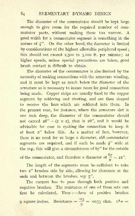
84 ELEMENTARY DYNAMO DESIGN
The diameter of the commutator should be kept large
enough to give room for the required number of com-
mutator parts, without making these too narrow. A
good width for a commutator segment is something in the
nature of J". On the other hand, the diameter is limited
by considerations of the highest allowable peripheral speed ;
this should not exceed 2,500 to 3,000 ft. per minute;
at
higher speeds, unless special precautions are taken, goodbrush contact is difficult to obtain.
The diameter of the commutator is also limited by the
necessity of making connections with the armature winding,
and it must be kept as much below the diameter of the
armature as is necessary to insure room for good connection
being made. Copper strips are usually fixed to the copper
segment by soldering and riveting, and are then shaped
to receive the bars which are soldered into them. In
the present case, for instance, where the armature slot is
one inch deep, the diameter of the commutator should
not exceed 28" (i X 2), that is 26", and it would be
advisable for ease in making the connection to keep it
at least 2" below this. As a matter of fact, however,
there is no need for so large a diameter, 268 commutator
segments are required, and if each be made J" wide at
the top, this will give a circumference of 67" for the outside
67of the commutator, and therefore a diameter of = 21".
7T
The length of the segments must be sufficient to take
two 2" brushes side by side, allowing for clearance at the
ends and between the brushes, say 5".
The current has to pass through both positive and
negative brushes. The resistance of one of these sets can
first be calculated. Thus : Area of positive brushes
9 square inches. Resistance = - = -0033 ohm. C 2 w
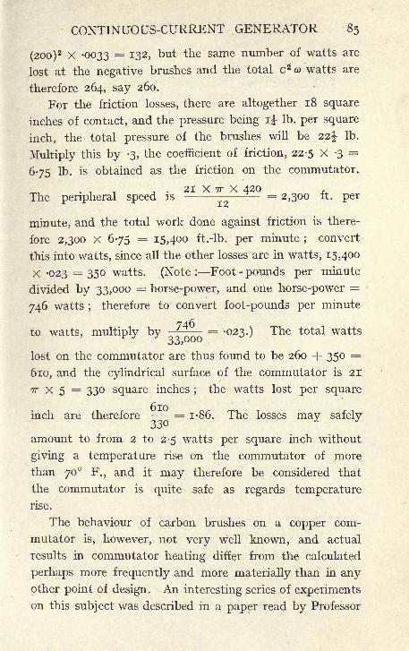
CONTINUOUS-CURRENT GENERATOR 85
(200)2 X -0033 = 132, but the same number of watts are
lost at the negative brushes and the total c 2 co watts are
therefore 264, say 260.
For the friction losses, there are altogether 18 square
inches of contact, and the pressure being ij Ib. per square
inch, the total pressure of the brushes will be 22% Ib.
Multiply this by -3, the coefficient of friction, 22-5 X -3=
675 Ib. is obtained as the friction on the commutator.
21 X TT X 420The peripheral speed is - = 2,300 ft. per12
minute, and the total work done against friction is there-
fore 2,300 X 675 = 15,400 ft.-lb. per minute ;convert
this into watts, since all the other losses are in watts, 15,400
X -023 = 350 watts. (Note : Foot - pounds per minute
divided by 33,000 = horse-power, and one horse-power =
746 watts ;therefore to convert foot-pounds per minute
to watts, multiply by^ = -023.) The total watts
lost on the commutator are thus found to be 260 + 350 =
610, and the cylindrical surface of the commutator is 21
TT x 5 = 330 square inches;
the watts lost per square
inch are therefore - = 1-86. The losses may safely
amount to from 2 to 2-5 watts per square inch without
giving a temperature rise on the commutator of more
than 70 F., and it may therefore be considered that
the commutator is quite safe as regards temperature
rise.
The behaviour of carbon brushes on a copper com-
mutator is, however, not very well known, and actual
results in commutator heating differ from the calculated
perhaps more frequently and more materially than in anyother point of design. An interesting series of experimentson this subject was described in a paper read by Professor
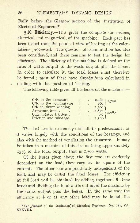
86 ELEMENTARY DYNAMO DESIGN
Baily before the Glasgow section of the Institution of
Electrical Engineers.*
10. Efficiency. This gives the complete dimensions,
electrical and magnetical, of the machine. Each part has
been tested from the point of view of heating as the calcu-
lations proceeded. The question of commutation has also
been considered, and there remains to test the design for
efficiency. The efficiency of the machine is defined as the
ratio of watts output to the watts output plus the losses.
In order to calculate it, the total losses must therefore
be found ; most of these have already been calculated in
dealing with the question of heating.
The following table gives all the losses on the machine :
C2R in the armature . ,. 2,460) 2 72OC2R in the commutator . . 260 }C2R in shunt winding . .
1,260^Armature iron . . . . , i, 870 ( 4 QgoCommutator friction . . . 350 C
Friction and windage f 1,500^
The last loss is extremely difficult to predetermine, as
it varies largely with the conditions of the bearings, and
also with the method of ventilating the armature. It maybe taken in a machine of this size as being approximately
14-% of the total output, that is 1,500 watts.
Of the losses given above, the first two are evidently
dependent on the load, they vary as the square of the
current. The other four are practically independent of the
load, and may be called the fixed losses. The efficiency
at full load will be obtained by adding together all these
losses and dividing the total watts output of the machine bythe watts output plus the losses. In the same way the
efficiency at \ or at any other load may be found, the
* See Journal of the Institution] of Electrical Engineers, No. 181, Vol.
XXXVIII.
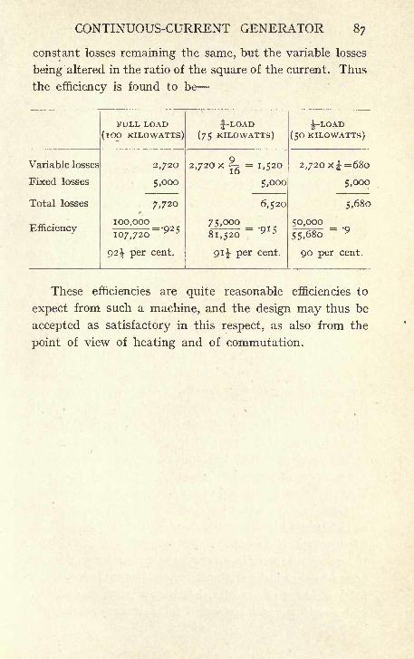
CONTINUOUS-CURRENT GENERATOR 87
constant losses remaining the same, but the variable losses
being altered in the ratio of the square of the current. Thus
the efficiency is found to be
These efficiencies are quite reasonable efficiencies to
expect from such a machine, and the design may thus be
accepted as satisfactory in this respect, as also from the
point of view of heating and of commutation.
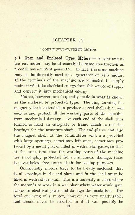
I
CHAPTER IV
CONTINUOUS-CURRENT MOTOR
1. Open and Enclosed Type Motors. A continuous-
current motor may be of exactly the same construction as
a continuous-current generator. In fact, the same machine
may be indifferently used as a generator or as a motor.
If the terminals of the machine are connected to supplymains it will take electrical energy from this source of supplyand convert it into mechanical energy.
Motors, however, are frequently made in what is knownas the enclosed or protected type. The ring forming the
magnet yoke is extended to produce a steel shell which will
enclose and protect all the working parts of the machine
from mechanical damage. At each end of the shell thus
formed is fixed an end-plate or frame which carries the
bearings for the armature shaft. The end-plates and also
the magnet shell, at the commutator end, are provided
with large openings, sometimes left open, sometimes pro-
tected by a metal grid or filled in with metal gauze, so that
at the same time that the working parts of the machine
are thoroughly protected from mechanical damage, there
is nevertheless free access of air for cooling purposes.
Occasionally motors have to be totally enclosed, that
is, all openings in the end-plates and in the shell must be
filled in with solid metal. This is a necessity in cases where
the motor is to work in a wet place where water would gain
access to electrical parts and damage the insulation. The
total enclosing of a motor, however, is very unadvisable,
and should never be resorted to if it can possibly be
88
CONTINUOUS-CURRENT MOTOR 89
avoided. The want of ventilation very largely increases the
heating so that, even with the increased temperature rise
which is usually allowed on totally enclosed motors, the
output of a machine of given size has to be very greatly
reduced when the machine is made totally enclosed instead
of being provided with ventilating grids.
Whilst both open and enclosed types of machine maybe used either as generator or motor, it is nevertheless
usual to find all generators made of the open type. Motors
are found of both types, but in these the enclosed type
probably prevails. The reason for this preference is
doubtless'
that whilst the generator is usually placed in an
engine-room, and has the benefit of the constant attention
of an attendant, motors are scattered all over the work-
shops in all sorts of situations. They are there exposed
to dirt and dust, and are often placed in such inaccessible
positions that they get very little attention. If they
had no protection they would, when placed amongst the
tools of an engineering works, for instance, be very liable to
mechanical damage, and for these reasons they are generally
afforded the protection of an enclosed shell.
This, however, does not apply to motors of the larger
sizes, say about 100 H.P., where the construction becomes
mechanically difficult, and where the open type is therefore
preferred. Motors, like generators, may be either series, or
shunt, or compound wound. For ordinary industrial pur-
poses the shunt-wound motor is the one most frequently
used. The excitation of the machine is independent of the
load since the magnet winding is connected directly across
the mains, and the speed will, therefore, be approximatelyconstant. This is the condition which is most convenient
for driving shafting, and for general shop purposes.
2. Principle of Back E.M.F. The principle on
which a continuous-current machine works as a motor is
90 ELEMENTARY DYNAMO DESIGN
as follows. When a current is passed through the armature
winding, the armature conductors, which are at the moment
in a strong magnetic field, will tend to move in a direction at
right angles to this field. This will give a torque tending
to rotate the armature. But as soon as rotation begins,
the armature conductors are cutting lines of magnetic
force, and, therefore, an E.M.F. is produced in the winding.
This E.M.F. is in such a direction as to oppose the flow of
the current in the armature bars, and is on that account
generally referred to as the back E.'M.F. As the speed of
the armature increases, this back E.M.F. is also increased,
and cuts down the value of the current until the torque
due to the current is only just sufficient to overcome the
resistance of the load;thus the current automatically
adjusts itself to the load put on the motor.
If more load is put on the machine, it will slow down
slightly, the back E.M.F. will be smaller and more current
will flow through the armature. If c represents the current
in a motor armature, E the E.M.F. at the mains, &> the
resistance of the armature, and e the back E.M.F. in the
armature conductors, then
E ec = -
.-. c ft> = E e,0)
multiply both sides by c
... c 2ft> = EC ec,
or ec = EC c 2o>
but E c represents the watts supplied from the main circuit,
and c 2 w the watts lost in the armature copper, the term
e c therefore represents the watts available for transforma-
tion into mechanical energy. From this it is seen that the
amount of electrical energy capable of conversion into
mechanical is equal to the current multiplied by the back
E.M.F. It must, however, be noted that the whole of this
is not available as useful work;the losses occurring in the
CONTINUOUS-CURRENT MOTOR 91
motor itself must be deducted. The efficiency of the motorP C^ P
can therefore never exceed = - and in practice will alwaysEC E
be less than this amount. And ec is less than EC by the
amount C 2o>. In order, then, that a reasonable efficiency
should be obtained, the value of co must be kept small.
This is also necessitated by the fact that if the watts lost
in the armature winding c 2co be large, the armature will
get too hot.
At the start, when the motor is standing still, e = o
and therefore c = - Since co is small, the current atCO
starting will be very large, many times the normal value of
the current. Hence the necessity of using a starting resist-
ance, which is inserted in series with the armature circuit,
and gradually cut out as the motor accelerates. This
resistance is chosen so as to keep the current down to
some predetermined value, and thus avoid possible damageto the motor, generating plant, and switch gear, from the
passage of an excessive current, and also possible mechanical
damage to the motor and driven machinery from too rapid
and sudden an acceleration.
3. Normal Rating of a Motor. It follows from
the above considerations that a motor may take from the
mains a much greater current than that at which it is
rated, and therefore give a much greater horse-powerthan that marked on its name-plate. A motor, for instance,
rated at 10 H.P. will, if called upon, do 20, 30, or even
more horse-power, but Unless the design has been quite
unduly liberal, it will get extremely hot if required to carrythe larger current for any length of time, and will spark
violently at the brushes.
The motor is rated at 10 H.P. because it will carry the
current corresponding to 10 H.P. with the specified tempera-
92 ELEMENTARY DYNAMO DESIGN
ture rise and efficiency, and without sparking at the com-
mutator, not because it is incapable of doing more than
10 H,P. if called upon to do so.
On referring to Chapter III. it will be seen that the
rating of a motor depends on exactly the same considerations
as that of a generator.
4. Design of 10 H.P. Motor at 600 Revolutions.
As an example, let it be required to design a motor to give
10 B.H.P. when running at 600 revolutions per minute on
a 500 -volt circuit. Many of the calculations required
will be identical with those for the continuous - current
generator, and will, therefore, serve as an additional arith-
metical example of the principles involved. The first
question to be solved is to determine the current which
the motor will be required to take at full load. In order
to do this, it is necessary that the efficiency of the motor
should be known, but as this cannot be calculated until the
design is complete, an efficiency is in the first place assumed,
subject to a revision of the calculations, should this be found
necessary when the real efficiency of the motor is ascertained.
For a motor of the required output it is safe to assume
an efficiency of about 83 %, which means that in order to
obtain 10 B.H.P. from the motor, it will be necessary to put
in -7T = 12 E.H.P., but one horse-power is equal to 746
watts, and therefore the necessary input will be 12 X 746= 9,000 watts. The watts are the product of the volts
and amperes, and, therefore, the current at full load must
_ 9,000be = 18 amperes.500
The diameter and length of core of the armature are
the most important dimensions of the machine. A ten-
tative value for 'these may be found, as in the case of the
generator, by using a curve connecting d 2l and D, which is
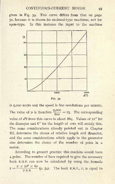
CONTINUOUS-CURRENT MOTOR 93
given in Fig. 39. This curve differs from that on page
50, because it is drawn for enclosed-type machines, not for
open-type. In this instance the input to the machine
D
40
30
20
10
IOOO 2000
FIG. 39.
is 9,000 watts and the speed is 600 revolutions per minute.
The value of D is therefore ^ = 15. The corresponding
value of d 2l from this curve is about 864. Values of 12" for
the diameter and 6" for the length of core will satisfy this.
The same considerations already pointed out in Chapter
III. determine the choice of relative length and diameter,
and the same considerations which apply to the generator
also determine the choice of the number of poles in a
motor.
According to present practice this machine would have
4 poles. The number of bars required to give the necessary
back E.M.F. can now be calculated by using the formula
E x io8 x 60 .
z = -(p. 54). The back E.M.F., E, is equal to
94 ELEMENTARY DYNAMO DESIGN
the E.M.F. of supply less the volts dropped in the armature
circuit. Assuming these to be 23 volts, that is, rather
more than 4%, the back E.M.F. will be 477 volts. The
speed is known to be 600 revolutions, and the number
of poles is 4, and it is only required to find the value of
N, the number of magnetic lines per pole, in order to solve
the equation giving the number of bars. Since the machine
12 7Thas 4 poles the pole pitch is equal to - - = 9-5", and if
the pole arc be taken as -7 of the pole pitch, its value will be
9'5 X -7= 6-6". The area of the pole shoe will be the
pole arc multiplied by the length measured parallel to
the shaft;
this length is usually taken the same as that
of the armature core, in this instance 6".
The area of the pole shoe will thus be 6-6 x 6 39-6
square inches, and this multiplied by 6-45 gives 260 square
centimeters. The value of 7,000 lines per square centi-
meter in the air gap is a fairly usual value to work at,
and will give a value for N, the number of lines per pole,
of 260 X 7,000 = 1,800,000 lines per pole. These values
can now be substituted in the E.M.F. formula
477 x 10 8 x 60z = -
T;= 660 bars to be connected
4 x 1,800,000 x 600
in series. If a wave winding is used, the total number
of bars will then be 1,320, but if lap winding is used, double
this number of bars, 2,640, will be required.
The wave winding would in this case be chosen in
preference to lap, from the point of view of convenience
of winding. Such a number as 2,640 wires would be
inconveniently large to wind on the armature, and the in-
dividual wires each having to carry only 4^ amperes, one-
quarter of the full current, since a lap winding gives four
paths in parallel through the armature, would be of small
section, and consequently a very large proportion of the
CONTINUOUS-CURRENT MOTOR 95
space in the slots would be taken up by insulation. It
is, therefore, better to choose the smaller number of bars,
1,320, and make use of a wave winding.
It is then necessary to put on the armature 1,320 bars,
and each of these bars will have to carry half of the full
load of current, that is 9 amperes. The ultimate criterion
of the bars being sufficiently large is that the number of
watts lost in the copper winding shall not be too high, but
as this loss can only be calculated when the winding has
been determined upon, it is best first to settle the size
of bar from consideration of the current density at which
it is advisable to, work. The density of 2,500 amperes
to the square inch, going up to as high as 3,000, is usual
in this size of machine. A No. 16 S.W.G. copper wire has
an area of -0032 square inch, and will give a current
density of - = 2,800.0032
5. Number of Turns Allowable per Commutator
Section and Reactance Voltage. In Chapter III., in the
case of the generator where the number of bars was com-
paratively small, it was advisable, after the number of
bars and their section had been determined, immediately to
proceed to see how they could be disposed on the armature
and to make sure that there was room to accommodate
the requisite number. With a winding of a comparatively
large number of small wires, it is better first to consider
how many turns may be connected between two commutator
parts.
In large machines, carrying a considerable current in
each bar, it is seldom possible to have more than one turn
per commutator part without unduly increasing the reac-
tance voltage of the short-circuited coil. In a small machine,
where each wire carries only a small current, the case is
different, and it is, therefore, advisable to calculate the
96 ELEMENTARY DYNAMO DESIGN
maximum number of turns per commutator part allowable
before proceeding to consider how the wires can best be
allocated in the slots.
It should be clearly observed that the difference in the
order of operations here suggested is due not to the fact
that the machine now considered is a motor, whilst that in
Chapter III. was a generator, but to the fact that the
specified outputs lead in Chapter III. to a bar winding,
and in this case to a wire-wound armature.
E c m 20 x TT I .
Using the formula p=-
(see page 81), which
gives the reactance voltage, all the quantities are known
except m, the number of turns per section;the reactance
voltage should not exceed 2 volts, if good commutation is
to be obtained without change of brush position.
500 xi8xwx2ox?rx6Substituting^
4 x x.8 x 10"
2 x 4 x 1-8 x io 6
from which m -5 ^ 4-3,
500 x 18 x 20 x TT x 6
that is 5 turns per section would give a reactance voltage
greater than 2, and thus 4 turns is the largest number
that should be used.
Giving to m the value 4, and again substituting in the
formula for reactance voltage it is found that
500 Xl8X4X20X?rX6p == - = 1-88 volt.
4 x 1-8 x io6
6. Number and Size of Slots. The number of coils
in each slot may be three, four or five;a greater number is
not advisable as it may cause the commutator to mark
through the coils not being in exactly the same magnetic
field as the moment of reversal. It should be pointed
out that the freedom of choice in this respect is more limited
with a wire winding than with a bar winding. The bar,
so long as its section is kept the same, may be made of
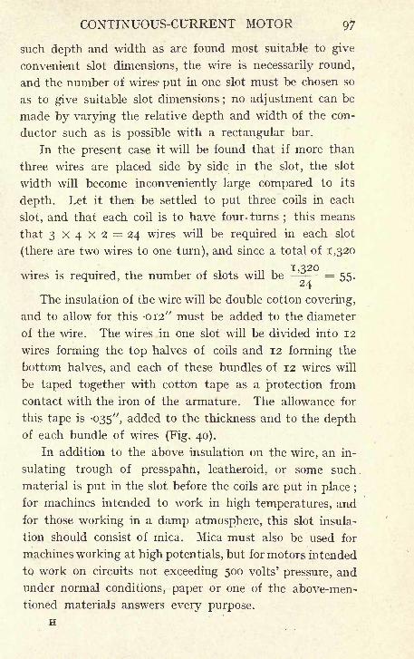
CONTINUOUS-CURRENT MOTOR 97
such depth and width as are found most suitable to give
convenient slot dimensions, the wire is necessarily round,
and the number of wires' put in one slot must be chosen so
as to give suitable slot dimensions ;no adjustment can be
made by varying the relative depth and width of the con-
ductor such as is possible with a rectangular bar.
In the present case it will be found that if more than
three wires are placed side by side in the slot, the slot
width will become inconveniently large compared to its
depth. Let it then be settled to put three coils in each
slot, and that each coil is to have four- turns;this means
that 3 x 4 X 2 = 24 wires will be required in each slot
(there are two wires to one turn), and since a total of 1,320
wires is required, the number of slots will be = 55.
The insulation of the wire will be double cotton covering,
and to allow for this -012" must be added to the diameter
of the wire. The wires in one slot will be divided into 12
wires forming the top halves of coils and 12 forming the
bottom halves, and each of these bundles of 12 wires will
be taped together with cotton tape as a protection from
contact with the iron of the armature. The allowance for
this tape is -035", added to the thickness and to the depthof each bundle of wires (Fig. 40).
In addition to the above insulation on the wire, an in-
sulating trough of presspahn, leatheroid, or some such
material is put in the slot before the coils are put in place ;
for machines intended to work in high temperatures, and
for those working in a damp atmosphere, this slot insula-
tion should consist of mica. Mica must also be used for
machines working at high potentials, but for motors intended
to work on circuits not exceeding 500 volts' pressure, and
under normal conditions, paper or one of the above-men-
tioned materials answers every purpose.
H
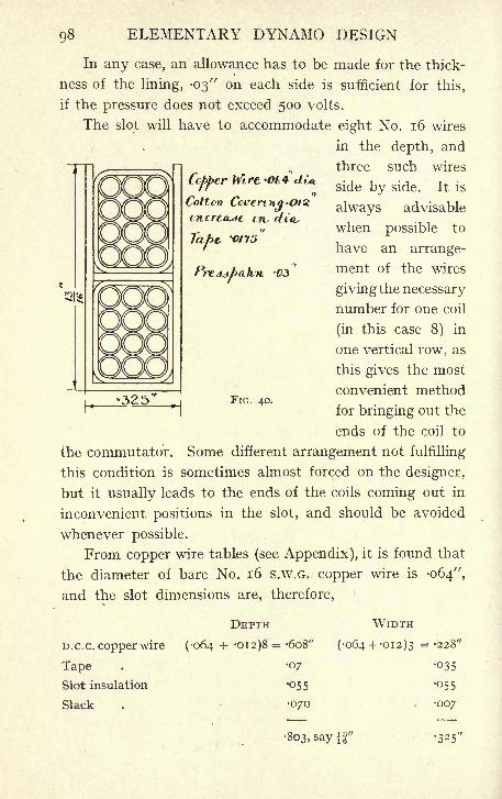
98 ELEMENTARY DYNAMO DESIGN
Ccf>f>erWirt *t4
Cotton Ccvemt.in,
In any case, an allowance has to be made for the thick-
ness of the lining, -03" on each side is sufficient for this,
if the pressure does not exceed 500 volts.
The slot will have to accommodate eight No. 16 wires
in the depth, and
three such wires
side by side. It is
always advisable
when possible to
have an arrange-
ment of the wires
giving the necessary
number for one coil
(in this case 8) in
one vertical row, as
this gives the most
convenient method
for bringing out the
ends of the coil to
the commutator. Some different arrangement not fulfilling
this condition is sometimes almost forced on the designer,
but it usually leads to the ends of the coils coming out in
inconvenient positions in the slot, and should be avoided
whenever possible.
From copper wire tables (see Appendix), it is found that
the diameter of bare No. 16 S.W.G. copper wire is -064",
and the slot dimensions are, therefore,
FIG. 40.
D.C.C. copper wire
Tape .
Slot insulation
Slack
DEPTH
(064 + '012)8 = -608"
07
055
070
WIDTH
064 + -012)3 = -228'
035
055
007
803, say
CONTINUOUS-CURRENT MOTOR 99
7. Inductions in Teeth. To make sure that this
is a suitable arrangement, and that there is room for this
number of slots, it is well now to calculate the resulting
densities at the bottom of the teeth as follows. The tooth
12 7T
pitch at the armature surface is - =-678, 12 TT being
03
the circumference of the armature. From this, subtract
325, the width of the slot, and there remains for the width
of each tooth at the top -353". Similarly at the bottom
of the slot, the diameter is 12" 2 X |f = iof", and
the tooth pitch isr =
-593. Again subtracting
325", the width of tooth at its narrowest part is
And since the pole arc is 7 of the pole pitch, the average
number of teeth under one pole will be X -7=
9-6.
To make allowance for the fringing of the magnetic field,
it will be necessary to add 10% to this, and the number
of teeth carrying the magnetic lines from one pole be-
comes 10-5.
It is now necessary to determine the effective length
of iron in the armature core. The total length of core is
6", and it is proposed that there should be two ventilating
ducts, each \" wide (Fig. 41) ; deducting these, there remains
5", of which 10% will be insulation between the discs
and the remaining 90% iron. The effective length will
therefore be 5 X '9= 4-5". The amount of iron at the
bottom of the teeth carrying the flux from one pole will,
therefore, be 10-5 X -268 x 4-5 = 12-4 ; multiply this by
6-45 to bring it to square centimeters, 12-4 X 6-45 =81-5
square centimeters, and the value of B, the induction at
the bottom of the teeth, is therefore' : - = 22,000.oi-5
Calculated in exactly the same way, the value of the in-
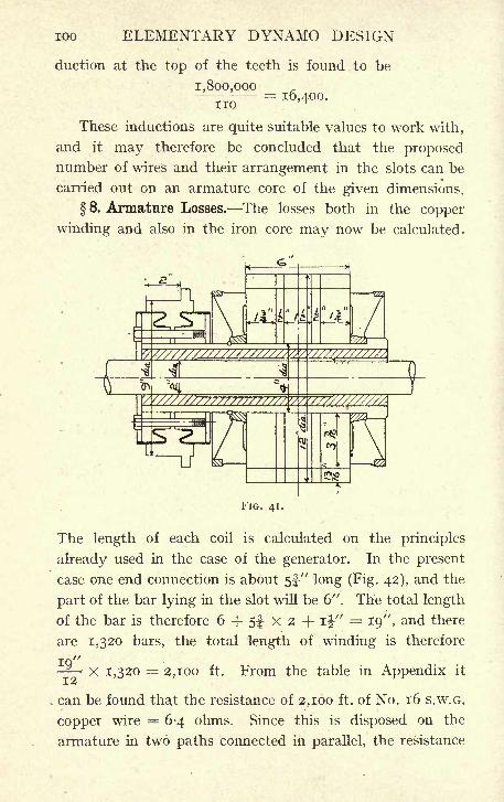
100 ELEMENTARY DYNAMO DESIGN
duction at the top of the teeth is found to be
1,800,000- = 16,400.noThese inductions are quite suitable values to work with,
and it may therefore be concluded that the proposednumber of wires and their arrangement in the slots can be
carried out on an armature core of the given dimensions.
8. Armature Losses. The losses both in the copper
winding and also in the iron core may now be calculated.
FIG. 41.
The length of each coil is calculated on the principles
already used in the case of the generator. In the present
case one end connection is about 5f" long (Fig. 42), and the
part of the bar lying in the slot will be 6". The total length
of the bar is therefore 6 + 5f x 2 + ij" = 19", and there
are 1,320 bars, the total length of winding is therefore
IQ"-- x 1,320 == 2,100 ft. From the table in Appendix it
can be found that the resistance of 2,100 ft. of No. 16 S.W.G.
copper wire = 6-4 ohms. Since this is disposed on the
armature in two paths connected in parallel, the resistance
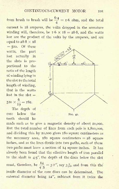
CONTINUOUS-CURRENT MOTOR 101
from brush to brush will be - = 1-6 ohm, and the total4
current is 18 amperes, the volts dropped in the armature
winding will, therefore, be 1-6 x 18 = 28-8, and the watts
lost are the product of the volts by the amperes, and are
equal to 28-8 x 18
= 510. Of these
watts, the part
lost actually in
the slots is pro-
portional to the
ratio of the length
of winding lying in
the slot to the total
length of winding,
that is the watts
lost in the slot =
510 x = 162.
The depth of
core below the FIG. 42.
teeth should be
made such as to give a magnetic density of about 10,000.
But the total number of lines from each pole is 1,800,000,
and dividing this by 10,000 gives 180 square centimeters as
the necessary area, 180 square centimeters = 28 square
inches, and as the lines divide into two paths, each of these
two paths must have a section of 14 square inches. It has
already been found that the effective length of iron parallel
to the shaft is 4-5", the depth of the discs below the slot
must, therefore, be -^= 3-1", say 3^, and from this the
i O
inside diameter of the core discs can be determined. The
external diameter being 12", subtract from it twice the
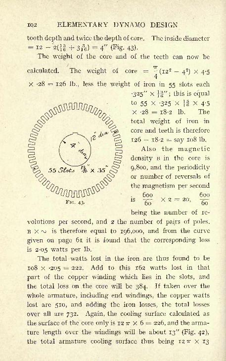
102 ELEMENTARY DYNAMO DESIGN
tooth depth and twice the depth of core. The inside diameter
= 12 -2(}| + 3ft) = 4" (Fig. 43).
The weight of the core and of the teeth can now be
7T
calculated. The weight of core (i22
42) X 4-5
4
X -28 = 126 Ib., less the weight of iron in 55 slots each
325" X f|" ;this is equal
to 55 X -325 X} J X 4-5
X -28 = 18-2 Ib. The
total weight of iron in
core and teeth is therefore
126 18-2 = say 108 Ib.
Also the magnetic
density B in the core is
9,800, and the periodicity
or number of reversals of
the magnetism per second
600 600IS -r- X 2 = 20, -r-
60 60
being the number of re-
volutions per second, and 2 the number of pairs of poles.
B X ^ is therefore equal to 196,000, and from the curve
given on page 61 it is found that the corresponding loss
is 2-05 watts per Ib.
The total watts lost in the iron are thus found to be
108 X -205 = 222. Add to this 162 watts lost in that
part of the copper winding which lies in the slots, and
the total loss on the core will be 384. If taken over the
whole armature, including end windings, the copper watts
lost are 510, and adding the iron losses, the total losses
over all are 732. Again, the cooling surface calculated as
the surface of the core only is 12 TT x 6 = 226, and the arma-
ture length over the windings will be about 13"
(Fig. 42),
the total armature cooling surface thus being 12 TT x 13
FIG. 43.
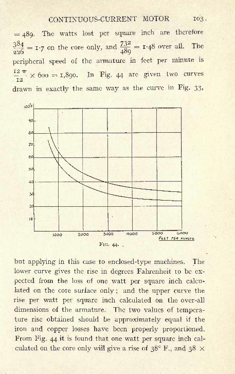
CONTINUOUS-CURRENT MOTOR 103
= 489. The watts lost per square inch are therefore
5^4 = 1-7 on the core only, and 23? = 1*48 over all. The226 ' 4oQ
peripheral speed of the armature in feet per minute is
^L x 600 = 1,890. In Fig. 44 are given two curves
drawn in exactly the same way as the curve in Fig. 33,
100 F
60
2000 3000 4000
FIG. 44. .
5OOO 6OOOFELT PER ntiv
but applying in this case to enclosed-type machines. The
lower curve gives the rise in degrees Fahrenheit to be ex-
pected from the loss of one watt per square inch calcu-
lated on the core surface only ;and the upper curve the
rise per watt per square inch calculated on the over-all
dimensions of the armature. The two values of tempera-
ture rise obtained should be approximately equal if the
iron and copper losses have been properly proportioned.
From Fig. 44 it is found that one watt per square inch cal-
culated on the core only will give a rise of 38 F., and 38 X
104 ELEMENTARY DYNAMO DESIGN
1 '7 65 F. Calculated over all, one watt per square inch
gives a rise of 48 F., and 48 X 1-48 = 71 F. The tempera-ture rise on the armature may therefore be expected to
be about 70 F., and the design considered satisfactory as
far as the armature temperature rise is concerned.
The dimensions of the steel magnets may now be con-
sidered.
9. Dimensions of the Magnets. The magnets will
have to be of sufficient section to carry the full number
of magnetic lines, that is 1,800,000, and in addition to this
whatever number of lines is allowed for leakage. If the
shell is made of cast steel, as is often the case, the total
magnetic density should not exceed about 13,000 lines to
the square centimeter, which gives a required area of
1,800,000- = 138 square centimeters, multiply by 1-2 to13,000
allow for leakage, and the area must be 166 square centi-
meters -7 =26 square inches, and supposing that the;45
magnet core, measured parallel to the shaft, is made the
same length as the armature, namely 6", this will give
a width of core, measured perpendicularly to the shaft, of
^ = 4-3", say 4i"-'
V
To determine what portion of the yoke is effective for
carrying lines is more difficult in the case of enclosed
machines than in one of the open type. The casting form-
ing the yoke is extended in order to give mechanical pro-
tection to the electrical parts. The path of any magnetic
lines running through the ends of the casting is evidently
much longer than that of lines keeping to the central
portion, the magnetic density is therefore reduced in those
parts, and they are magnetically less effective. It is a
matter of some difficulty to say what allowances must be
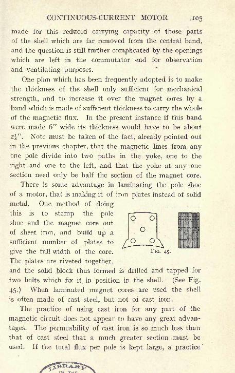
CONTINUOUS-CURRENT MOTOR 105
made for this reduced carrying capacity of those parts
of the shell which are far removed from the central band,
and the question is still further complicated by the openings
which are left in the commutator end for observation
and ventilating purposes.
One plan which has been frequently adopted is to make
the thickness of the shell only sufficient for mechanical
strength, and to increase it over the magnet cores by a
band which is made of sufficient thickness to carry the whole
of the magnetic flux. In the present instance if this band
were made 6" wide its thickness would have to be about
2\" . Note must be taken of the fact, already pointed out
in the previous chapter, that the magnetic lines from anyone pole divide into two paths in the yoke, one to the
right and one to the left, and that the yoke at any one
section need only be half the section of the magnet core.
There is some advantage in laminating the pole shoe
of a motor, that is making it of iron plates instead of solid
metal. One method of doing
this is to stamp the pole
shoe and the magnet core out
of sheet iron, and build up a
O O
O
sufficient number of plates to /Qgive the full width of the core. FIG. 45.
The plates are riveted together,
and the solid block thus formed is drilled and tapped for
two bolts which fix it in position in the shell. (See Fig.
45.) When laminated magnet cores are used the shell
is often made of cast steel, but not of cast iron.
The practice of using cast iron for any part of the
magnetic circuit does not appear to have any great advan-
tages. The permeability of cast iron is so much less than
that of cast steel that a much greater section must be
used. If the total flux per pole is kept large, a practice
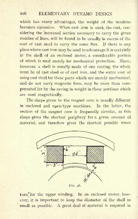
io6 ELEMENTARY DYNAMO DESIGN
which has many advantages, the weight of the machine
becomes excessive. When cast iron is used, the cost, con-
sidering the increased section necessary to carry the given
number of lines, will be found to be usually in excess of the
cost of cast steel to carry the same flux. If there is any
place where cast iron may be used to advantage it is certainly
in the shell of an enclosed motor, a considerable portion
of which is used merely for mechanical protection. Since,
however, a shell is usually made of one casting, the whole
must be of cast steel or of cast iron, and the extra cost of
using cast steel for these parts which are merely mechanical,
and do not carry magnetic lines, may be more than com-
pensated for by the saving in weight in those portions which
are used magnetically.
The shape given to the magnet core is usually different
in enclosed and open-type machines. In the latter, the
section of the magnet core is frequently circular, as this
shape gives the shortest periphery for a given amount of
material, and therefore gives the shortest possible mean
FIG. 46.
turnr for the upper winding. In an enclosed motor, how-
ever, it is important to keep the diameter of the' shell as
small as possible. A great deal of material is required in
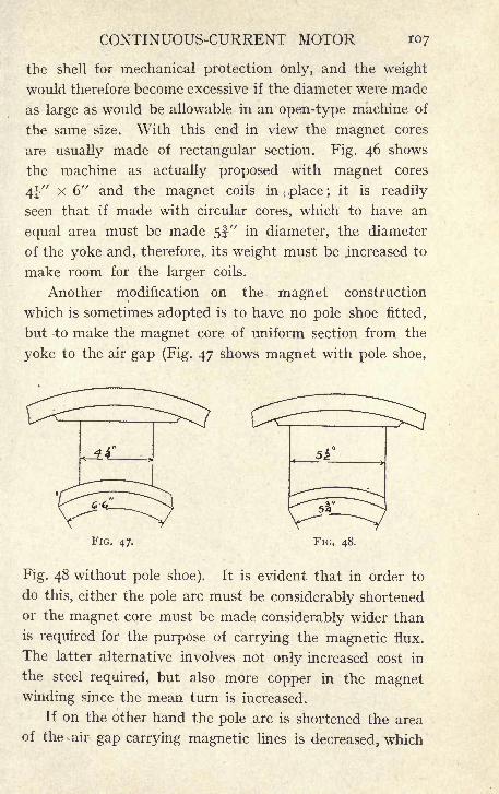
CONTINUOUS-CURRENT MOTOR 107
the shell for mechanical protection Only, and the weight
would therefore become excessive if the diameter were made
as large as would be allowable in an open-type machine of
the same size. With this end in view the magnet cores
are usually made of rectangular section. Fig. 46 shows
the machine as actually proposed with magnet cores
4^" X 6" and the magnet coils in place ;it is readily
seen that if made with circular cores, which to have an
equal area must be made 5f-"
in diameter, the diameter
of the yoke and, therefore, its weight must be .increased to
make room for the larger coils.
Another modification on the magnet construction
which is sometimes adopted is to have no pole shoe fitted,
but to make the magnet core of uniform section from the
yoke to the air gap (Fig. 47 shows magnet with pole shoe,
FIG. 47. FIG. 48.
Fig. 48 without pole shoe). It is evident that in order to
do this, either the pole arc must be considerably shortened
or the magnet core must be made considerably wider than
is required for the purpose of carrying the magnetic flux.
The latter alternative involves not only increased cost in
the steel required, but also more copper in the magnetwinding since the mean turn is increased.
If on the other hand the pole arc is shortened the area
of the . air gap carrying magnetic lines is decreased, which
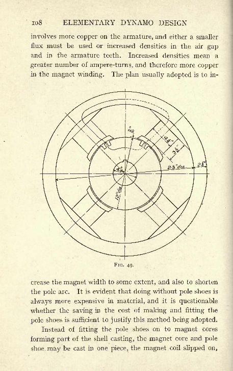
io8 ELEMENTARY DYNAMO DESIGN
involves more copper on the armature, and either a smaller
flux must be used or increased densities in the air gapand in the armature teeth. Increased densities mean a
greater number of ampere-turns, and therefore more copper
in the magnet winding. The plan usually adopted is to in-
FIG. 49. . ,
crease the magnet width to some extent, and also to shorten
the pole arc. It is evident that doing without pole shoes is
always more expensive in material, and it is questionable
whether the saving in the cost of making and fitting the
pole shoes is sufficient to justify this method being adopted.
Instead of fitting the pole shoes on to magnet cores
forming part of the shell casting, the magnet core and pole
shoe may be cast in one piece, the magnet coil slipped on,
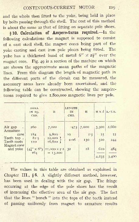
CONTINUOUS-CURRENT MOTOR 109
and the whole then fitted to the yoke, being held in place
by bolts passing through the shell. The cost of this method
is about the same as that of fitting on separate pole shoes.
10. Calculation of Ampere-turns required. In the
following calculations the magnet is supposed to consist
of a cast steel shell, the magnet cores being part of the
yoke casting and cast iron pole pieces being fitted. The
yoke has a thickened band of metal 6" X 2$"' over the
magnet core. Fig. 49 is a section of the machine on which
are shown the approximate mean paths of the magnetic
lines. From this diagram the length of magnetic path in
the different parts of the circuit can be measured, the
necessary areas have already been ascertained, and the
following table can be constructed, showing the ampere-
turns required to give 1,800,000 magnetic lines per pole.
The values in this table are obtained as explained in
Chapter III., 6. A slightly different method, however,
has been used in dealing with the air gap. The fringe
occurring at the edge of the pole shoes has the result
of increasing the effective area of the air gap. The fact
that the lines" bunch "
into the tops of the teeth instead
of passing uniformly from magnet to armature results
no ELEMENTARY DYNAMO DESIGN
in decreasing the effective area of the air gap ;in small
machines it is often assumed that these two effects will
neutralise one another. Instead, therefore, of making a
separate allowance for each, as was done in Chapter III.,
no allowance has been made for either, it being assumed
that they would be approximately equal and, since theyare of opposite effect, would cancel out.
11. Winding of Magnet Coils. The winding of the
magnets may, as in the case of a generator, be either shunt,
or series, or compound. The different windings will, in the
case of the motor, affect not the voltage, since the E.M.F.
of supply is kept constant, but the speed.
The series-wound motor will run at a high speed under
light loads, and the speed will fall as the load increases.
In all but the smallest motors, where the efficiency is poor,
the speed may become dangerously high, if the load is
suddenly thrown off, and it is unusual to use series-wound
motors except in cases where the conditions are such as to
insure some load being always kept on the machine.
Motors for cranes and for traction purposes are usually
geared to the -load, and the power required to drive the
gear will be sufficient to prevent dangerous racing. In all
such cases, the use of series winding is allowable. Whenthe motor, however, drives the load through belting, there
is a liability, if the belt break, or come off, that the motor
should remain connected to the mains with no load on it,
in which case the speed may become so high as to damagethe armature or commutator, on account of the high
peripheral speed.
The winding adopted for motors driving machinery
in various industries is usually shunt winding. A shunt-
wound motor will run at approximately the same speed,
whatever the load, and this condition is the most useful
for general purposes. There is, however, a slight drop
CONTINUOUS-CURRENT MOTOR in
in speed, as the load increases, due to the increased
armature losses. It has been seen in the case of a shunt-
wound generator that there is some drop in E.M.F. as the
load increases, and this can be compensated for by putting
on a few turns of series winding on the magnets in addition
to the shunt turns. The same device may be adopted
in the case of the motor in order to keep the speed abso-
lutely uniform whatever the load. It should be noted,
however, that in the case of the generator, the drop due
to the armature resistance is added to the effect of the back
armature ampere-turns, and both causes contribute to
lowering the E.M.F. with increased load. In the case of
the motor, these causes act in opposition. With a given
E.M.F. of supply the drop in the armature conductor tends
to lower the speed, but the armature back ampere-turns
tend to increase it. Fewer series turns would, therefore, be
required on a motor than a generator.
It is also of minor importance in ordinary circumstances
that a motor should keep at absolutely the same speed, and
it is accordingly unusual to find motors compound-woundfor the purpose of keeping their speed constant.
Motors are, however, very frequently compound-woundfor another purpose. In this case the series turns are
wound so as to increase the magnetisation of the machine ;
they act with the shunt, not in opposition to it. The result
of this is still further to increase the change of speed with
change of load, but it has also the effect of giving a very
strong field at starting, when a big rush of current passes
through the series turns. It, therefore, increases the torque
at starting, and has the effect of greatly improving the
behaviour of the brushes under fluctuating loads, since it
causes the field to increase at those times when a big arma-
ture current has to be reversed.
A compound-wound motor with the shunt and series
H2 ELEMENTARY DYNAMO DESIGN
coils acting together is therefore a useful machine in cases
when the apparatus has to be frequently started under full
load or where large and frequent fluctuations of load take
place. The exact amount of series winding to be put on
for this purpose is indeterminate. The greater the number
of series turns the better the starting torque, but this
is obtained at the cost of a worse speed regulation. Afrequent compromise is to calculate the necessary ampere-turns at full load, and to put on about a quarter of these,
as series turns, the other three-quarters as shunt turns.
In the present instance it is proposed to put on the
magnets a simple shunt winding. From the table on
page 109, 3,400 ampere-turns are required on each pole ;
add about 10% margin, say 3,700 ampere-turns. It is
required to find the proper size of wire, in order to have
on each magnet 3,700 ampere-turns, and how many turns
of such wire are necessary in order to keep the tempera-
ture-rise within the specified limit.
The winding space may be tried as 3" x 3". Allow-
ing J" clearance on each side of the core, I" for insula-
tion, and y as clearance, to insure the coil slipping on
easily, the mean length of one turn will be
2 (6J + 4t) + 3 T + i" = 33-5"-
The cooling surface is taken as one end of the coil added
to the surface of the coil round its periphery. The end
surface (the area shown in Fig. 50) may be taken as the mean
turn X 3" = 33'5 X 3 = 100-5 square inches. The outside
periphery of the coil is equal to 2 (6J + 4f ) + 6rr -f- 2 = 44",
and this multiplied by 3", the depth of the coil, gives
132 square inches for the sides of the coil. These two areas
added together give 132 + 100*5 = 232^5 square inches as
the value of the cooling surface.
Allowing -6 of a watt to be radiated per square inch,
this allows of 140 watts being lost in each coil. Since
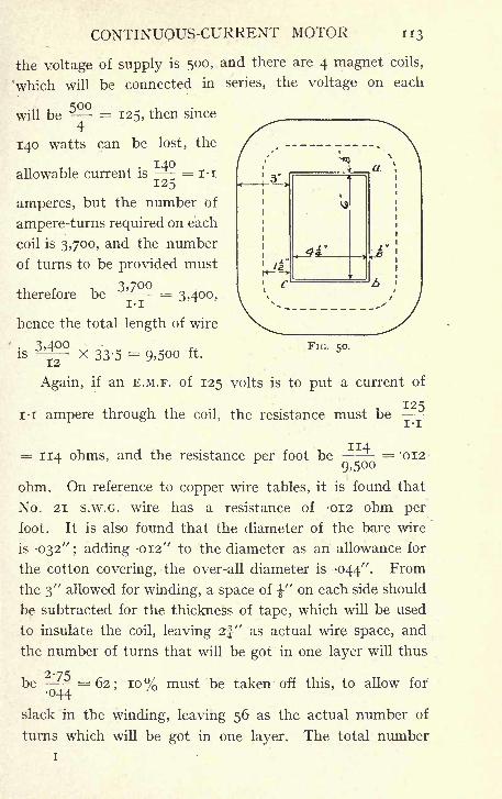
CONTINUOUS-CURRENT MOTOR
the voltage of supply is 500, and there are 4 magnet coils,
'which will be connected in series, the voltage on each
will be - = 125, then since4
140 watts can be lost, the
140allowable current is = i-i
amperes, but the number of
ampere-turns required on each
coil is 3,700, and the number
of turns to be provided must
therefore be = 3,400,
hence the total length of wire
3400
NCQ
__L
VS
ft
J"
IS12
x 33'5 = 9.500 ft.FIG. 50.
Again, if an E.M.F. of 125 volts is to put a current of
125i-i
i -i ampere through the coil, the resistance must be
= 114 ohms, and the resistance per foot be = '0129.500
ohm. On reference to copper wire tables, it is found that
No. 21 s.w.G. wire has a resistance of -012 ohm per
foot. It is also found that the diameter of the bare wire
is -032" ; adding -012" to the diameter as an allowance for
the cotton covering, the over-all diameter is -044". From
the 3" allowed for winding, a space of -J-" on each side should
be subtracted for the thickness of tape, which will be used
to insulate the coil, leaving 2j" as actual wire space, and
the number of turns that will be got in one layer will thus
be 275044
= 62; 10% must be taken off this, to allow for
slack in the winding, leaving 56 as the actual number of
turns which will be got in one layer. The total number
i
H4 ELEMENTARY DYNAMO DESIGN
of turns required has been found to be about 3,400, the
number of layers is therefore^
= 60. The space
required for 60 layers is 60 x -044 = 2-64", add 10% allow-
ance for slack say 2-9", so that the magnet coil will easily
go into the space, 3" x 3", previously allowed for it.
The weight of this wire will be 9,500 x -0031 = 28 lb.
per coil = 112 lb. for the 4 coils, -0031 lb. being, as shown
in the table, the weight of one foot of No. 21 s.w.G. wire.
12. Dimensions of the Commutator. The commutator
to collect a current of 18 amperes will have to be about 9"in diameter, and about 2" long (Fig. 41). Four spindles
carrying brushes should be used, and assuming that one
brush I" x i" is put at each commutating point,
there will be altogether 2 positive brushes having a total
area of i x f X 2 = 2|- square inches. Again taking the
contact resistance of carbon as -03 ohm per square inch,
the resistance of the positive brushes will be -^- = '0133
ohm, and the resistance of the positive and negative brushes
together will be double this, -027 ohm. The voltage lost at
the commutator will therefore be 18 x -027=
-48 and
48 X 18 = 9 watts will be lost.
Again, the peripheral speed of the commutator is
X 600 = 1,400 ft. per minute. If the pressure on12 ,
the brushes be ij lb. to the square inch, the total pressure
will be ij X 4^ = 5-6 lb., and assuming that the coefficient
of friction is -3 this will give a tangential force of 5-6 x '3= 17
lb., and this multiplied by the peripheral speed gives
1-7 x 1,400 = 2,400 ft. lb. per minute as the rate of doing
work against the friction of the brushes - =-073
3
H.P., and -073 X 746 = 54 watts.
CONTINUOUS-CURRENT MOTOR 115
There are thus lost altogether on the commutator
9 watts in c 2w, and 54 watts in friction losses, giving the
total of 63 watts, and the cooling surface from which these
are to be got rid of is = 9 IT X 2 = 56, giving -g=1-12
watt per square inch.
It would be quite possible to lose from two to two and a
half times this amount of watts without any fear of serious
heating, and from this point of view it might be considered
that the dimensions of the commutator are too liberal.
It is, however, inadvisable to shorten the commutator
to any great extent as the clamping of the commutator
segments becomes difficult if they are extremely short.
The diameter cannot be reduced, for as there are 165 com-
mutator parts, the thickness of one commutator part
and its insulation is already as small as -7 =-17''', and
any considerable reduction of diameter would make the
parts too thin to be conveniently handled.
Some saving might be effected by. reducing the number
of brushes to two; it has already been seen (Chapter II.)
that with a four-pole wave-wound armature it is possible
to collect at two commutating points only ;the objections
to this course are that there would then be only one positive
and one negative brush on the machine;
it is always ad-
visable to avoid this when possible, for if one brush only
is carrying the whole current it is impossible to lift it
off the commutator when the machine is running ; any slight
accident to the one brush therefore means stopping down,
whilst with two or more brushes carrying current it is
possible to lift the defective brush off the commutator
and keep running with the others.
Also, if the argument in Chapter III., on which is based
the calculation of reactance voltage, be referred to, it will
n6 ELEMENTARY DYNAMO DESIGN
be seen that it depends on having only one coil short-
circuited between the brushes;but on a four-pole machine
having brushes only at two commutating points, there are
two such coils in series and the reactance voltage should
therefore be doubled.
In practice it is found that there is no such marked
difference as indicated above and, as a general rule, a
machine which works satisfactorily with four sets of brushes
will also give good commutation with two only. There are,
however, cases occasionally met with where a machine
does not give very good results, and sparks to a slight
extent with two sets of brushes, and is very much im-
proved and becomes quite satisfactory with four sets.
13. Calculation of Efficiency. To consider now the
efficiency of the 10 H.-P. motor dealt with in this chapter,
it is merely necessary to collect together the losses which
have been already calculated, and see what percentage
they bear to the output. It is necessary, however, to
make an allowance for the friction at the bearings, and
for air friction ;this is not readily calculable, but may
be taken for such a machine as this, at about 3J% of the
output, say 250 watts.
The losses then are :
c 2G) in armature winding . . . . 510 watts
Iron losses in armature . . . . 222 ,,
Losses in shunt winding . . . . 560 ,,
Losses in commutator . . . . 63 ,,
Friction and windage losses . . . . 250 ,,
Total . . . . 1,605
and the required output is 10 H.P. = 7,460 watts, the input
will then be 7,460 + 1,600 = 9,060, and the full load
efficiency will be = -83 or 83%.9,000
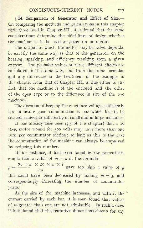
CONTINUOUS-CURRENT MOTOR 117
14. Comparison of Generator and Effect of Size.
On comparing the methods and calculations in this chapter
with those used in Chapter III., it is found that the same
considerations determine the chief lines of design whether
the machine is to be used as generator or motor.
The output at which the motor may be rated depends,
in exactly the same way as that of the generator, on the
heating, sparking, and efficiency resulting from a given
current. The probable values of these different effects are
calculated in the same way, and from the same formulae,
and any difference in the treatment of the example in
this chapter from that of Chapter III. is due either to the
fact that one machine is of the enclosed and the other
of the open type or to the difference in size of the two
machines.
The question of keeping the reactance voltage sufficiently
low to insure good commutation is one which has to be
treated somewhat differently in small and in large machines.
It has already been seen ( 5 of this chapter) that a 10
H.-P. motor wound for 500 volts may have more than one
turn per commutator section;so long as this is the case
the commutation of the machine can always be improved
by reducing this number.
If, for instance, it had been found in the present ex-
ample that a value of m = 4 in the formula
EC x m x 20 x TT x I
p= - -
gave too high a value of p
this could have been decreased by making m =3, and
correspondingly increasing the number of commutator
parts.
As the size of the machine increases, and with it the
current carried by each bar, it is soon found that values
of m greater than one are not admissible. In such a case,
if it is found that the tentative dimensions chosen for any
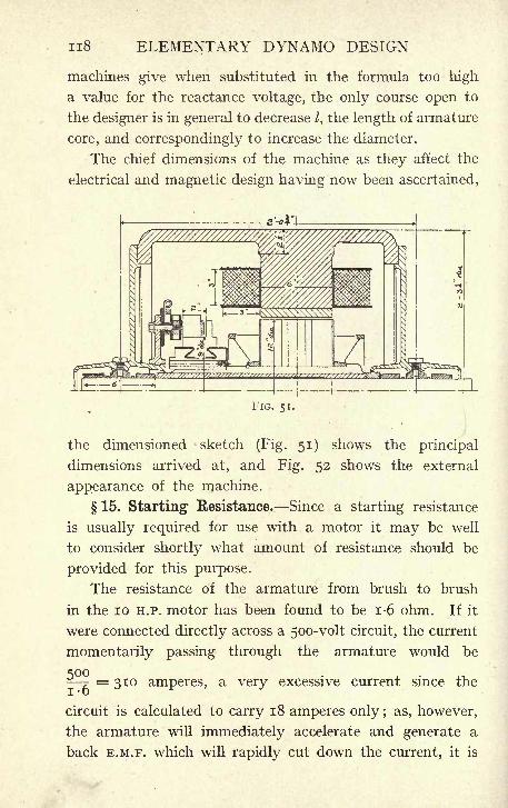
n8 ELEMENTARY DYNAMO DESIGN
machines give when substituted in the formula too high
a value for the reactance voltage, the only course open to
the designer is in general to decrease /, the length of armature
core, and correspondingly to increase the diameter.
The chief dimensions of the machine as they affect the
electrical and magnetic design having now been ascertained,
FIG. 51.
the dimensioned sketch (Fig. 51) shows the principal
dimensions arrived at, and Fig. 52 shows the external
appearance of the machine.
15. Starting Resistance. Since a starting resistance
is usually required for use with a motor it may be well
to consider shortly what amount of resistance should be
provided for this purpose.
The resistance of the armature from brush to brush
in the 10 H.P. motor has been found to be 1-6 ohm. If it
were connected directly across a 5oo-volt circuit, the current
momentarily passing through the armature would be
- =310 amperes, a very excessive current since the
circuit is calculated to carry 18 amperes only ; as, however,
the armature will immediately accelerate and generate a
back E.M.F. which will rapidly cut down the current, it is
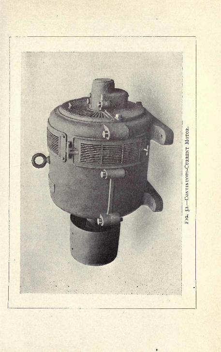
120 ELEMENTARY DYNAMO DESIGN
quite legitimate to allow more than the full load current
of the machine to pass through on the first step of the
starting resistance.
The greater the current allowed to pass, the greater
the bulk and cost of the resistance, for the size of resistance
required varies with the watts it has to dissipate, and these
vary directly as the resistance, but as the square of the
current. The suitable resistance to use in any case depends
upon the conditions under which the motor is required to
start. If it starts light, a resistance allowing only half
the normal current on the first step may be suitable;
if on
the other hand the motor starts against a heavy torque,
it may be necessary to allow as much as twice the normal
current to flow before the motor will start.
A resistance suitable for starting the motor considered
in this chapter light, might have about 54 ohms, this added
to the armature resistance of 1-6 ohm will give a total
resistance in circuit of 55-6 ohms, and the current will thus
be F = 9. The size of wire used should be such as
to carry this current for, say, half a minute, without
dangerous heating.
CHAPTER V
MECHANICAL DETAILS
1. Shaft. The mechanical design oi dynamo electric
machinery is carried out by means of the same rules as
that of any other class of machines. There are, however,
some points which are special to dynamo machinery, which
will now be considered.
The shaft is calculated of such a diameter as to resist
bending. The distance between the bearings is in manymachines considerable, and the weight of armature and
of commutator supported between them is such as to make
the torsional stress negligible in comparison to the bending.
In addition, if the armature gets slightly out of centre,
there is a strong magnetic pull tending to increase the
deflection, and the shaft must be strong enough to resist
this also. It is therefore usual to calculate the diameter
of the shaft so as to be stiff enough to give a deflection
not greater than a certain percentage of the air gap. In
present practice there is almost invariably provided a
spider which is keyed on to the shaft, and on which the
armature discs are threaded. The presence of the spider
adds materially to the stiffness of the shaft. It is usual,
however, to leave it out of account in the calculations,
and to take the benefit of it as an additional factor of safety,
and as a set off against any magnetic pull which may be
present.
Taking the case of the motor in Chapter IV., the weight
of armature and commutator for a 12" x 6" machine will
be about 260 lb., the distance between the centres of the
121
122 ELEMENTARY DYNAMO DESIGN
bearings will be 25", and the deflection due to this weightfor a shaft 2" diameter would amount to about -004".
This is calculated as follows :
P
The deflection of the shaft is treated as that of a beam
supported at both ends, and having the total weight con-
centrated at the centre (the load is assumed to be concen-
trated as this is the worst possible case) ;the formula for
wl 3
such a beam is d = -
48 E i
Where d is the deflection at the centre,
w is the weight in Ibs.,
/ the length between supports in inches,
E is the modulus of elasticity,
i is the moment of inertia of the section;for a
circular section I = ^ D4,
64
where D is the diameter in inches. Substituting in the
formula
w = 260 Ibs. = -116 ton,
I = 25"
E = 12,000 (the value usually taken for steel shafts),
116 x (25)3
~48^ X 12,000 X 785
And the radial depth of the air gap is TV' = -1875".
The percentage deflection is therefore
= -022, or 2-2%.
It is considered safe practice to make the shaft of such
diameter that the deflection calculated by the above formula
does not exceed 3% of the air gap.
The calculation of the magnetic pull due to a given
displacement is not easy, the strength of field varies at all
MECHANICAL DETAILS 123
points round the armature, and the magnetic pull is there-
fore different at every point of the circumference. Onlythose components of the pull which are parallel to the line
along which displacement has taken place are effective
in bending the shaft, and it is therefore difficult to obtain
an expression taking the whole of these considerations into
account.
An approximation can be obtained by considering
only those poles which are in a line with the displacement,
and assuming that these act as flat faces with a uniform
distribution of magnetic flux over them.
Thus, reverting again to the four-pole motor of
Chapter IV., assume that the displacement is directly
towards one pole and amounts to -004". Th6 air gapat one pole will be decreased from jV = -1875 to -1835" ;
at the opposite pole it will be increased to -1915". The
other two poles will give a side pull only, the forces will
be equal and opposite, and need not, therefore, be con-
sidered.
Assume that the value of B varies inversely as the
depth of air gap. The value of B, which is 7,000 lines per
square centimeter for a uniform air gap, will become 7,100
at the pole face which the armature has approached, and
AB 2
6,900 at the opposite pole. The pull is equal to ~ dynes
where A is the area of the opposing faces in square centimeters.
on, n -11 j-i -i260 x (7,ioo)
2
Ihe pull will therefore be - = 502 x io 6
O 7T
dynes at one, andX ( ,900) ^ x io 6 at theO 7T
other face, giving a total resultant pull of 502 x io 6489
X io 6 = 113 x io 6dynes. But 981 dynes = one gramme
and 1,000 grammes = 2-2 Ib. .-. i Ib. = - - = 44^,0002-2
^"J
24 ELEMENTARY DYNAMO DESIGN
dynes. The pull due to a displacement of -004" will
T TO \/ TQ 6
therefore amount to - = 254 Ib.445,000
This should really be added to the weight of the arma-
ture in considering the shaft deflection, but the fact that
the load has been considered as concentrated whilst it is
really distributed along the shaft, and also the fact that
the stiffening effect of the spider has been neglected, afford
such a large factor of safety, that it is safe to set them off
against the magnetic pull, and to leave this out of the
formula.
2. The Bearings. The bearings of the smaller - size
machines should have a length not less than three times
the diameter of the shaft;in the larger sizes this may be
reduced to 2j- diameters;
in exceptionally large machines
the bearing length is made even smaller than this propor-
tion.
The bearings of almost all dynamo-electric machines
are now made to be self-oiling, usually by means of ring
lubrication. The pedestal is cast so as to form an oil
reservoir of considerable capacity, and one or two brass
rings are threaded on to the shaft and dip into this oil
supply. The top half of the bush is slotted to receive
these rings so that they hang freely on the shaft. Whenthe shaft rotates, the rings rotate with it, and as they
are dipping in the oil, they bring up a sufficient supply
to keep the bearing well lubricated.
The oil after passing through the bearing is caught
by a lip cast on the pedestal which leads it back into
the reservoir, so that the bearings having once been filled
need no attention for a considerable time. A cock is pro-
vided at the bottom of the pedestal to run out the oil, and
at intervals when this has got dirty, the reservoir can be
emptied, cleaned, and refilled with fresh oil. It is also
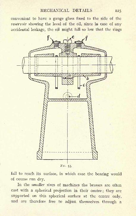
MECHANICAL DETAILS 125
convenient to have a gauge glass fixed to the side of the
reservoir showing the level of the oil, since in case of any
accidental leakage, the oil might fall so low that the rings
f
FIG. 53.
fail to reach its surface, in which case the bearing would
of course run dry.
In the smaller sizes of machines the brasses are often
cast with a spherical projection in their centre; they are
supported on this spherical surface at the centre only,
and are therefore free to adjust themselves through a
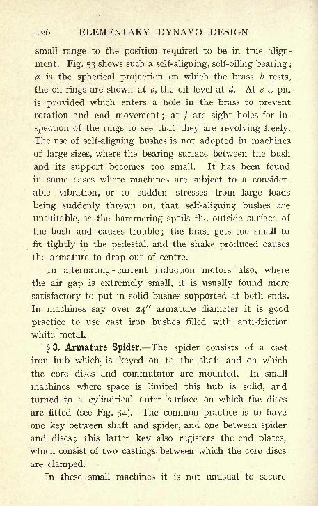
126 ELEMENTARY DYNAMO DESIGN
small range to the position required to be in true align-
ment. Fig. 53 shows such a self-aligning, self-oiling bearing ;
a is the spherical projection on which the brass b rests,
the oil rings are shown at c, the oil level at d. At e a pin
is provided which enters a hole in the brass to prevent
rotation and end movement;
at / are sight holes for in-
spection of the rings to see that they are revolving freely.
The use of self-aligning bushes is not adopted in machines
of large sizes, where the bearing surface between the bush
and its support becomes too small. It has been found
in some cases where machines are subject to a consider-
able vibration, or to sudden stresses from large loads
being suddenly thrown on, that self-aligning bushes are
unsuitable, as the hammering spoils the outside surface of
the bush and causes trouble; the brass gets too small to
fit tightly in the pedestal, and the shake produced causes
the armature to drop out of centre.
In alternating- current induction motors also, where
the air gap is extremely small, it is usually found more
satisfactory to put in solid bushes supported at both ends.
In machines say over 24" armature diameter it is good
practice to use cast iron bushes filled with anti-friction
white metal.
3. Armature Spider. The spider consists of a cast
iron hub which is keyed on to the shaft and on which
the core discs and commutator are mounted. In small
machines where space is limited this hub is solid, and
turned to a cylindrical outer surface on which the discs
are fitted (see Fig. 54). The common practice is to have
one key between shaft and spider, and one between spider
and discs;
this latter key also registers the end plates,
which consist of two castings between which the core discs
are clamped.
In these small machines it is not unusual to secure
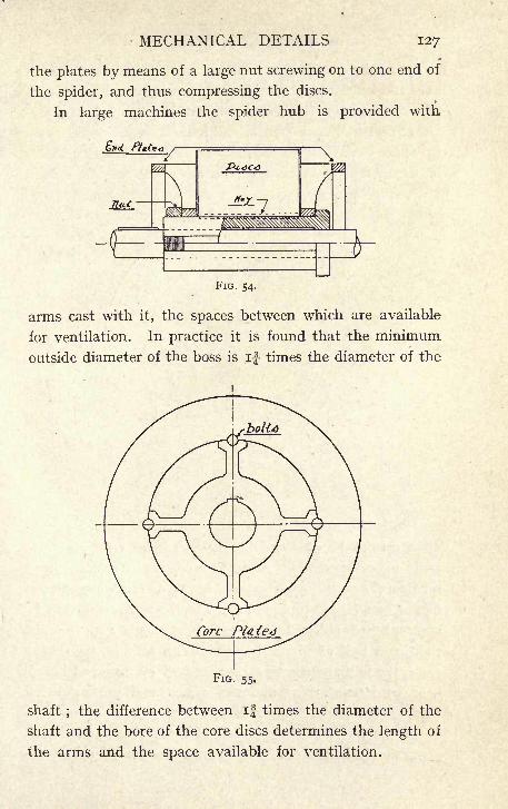
MECHANICAL DETAILS 127
the plates by means of a large nut screwing on to one end of
the spider, and thus compressing the discs.
In large machines the spider hub is provided with
FIG. 54.
arms cast with it, the spaces between which are available
for ventilation. In practice it is found that the minimum
outside diameter of the boss is if times the diameter of the
FIG. 55.
shaft;the difference between if times the diameter of the
shaft and the bore of the core discs determines the length of
the arms and the space available for ventilation.
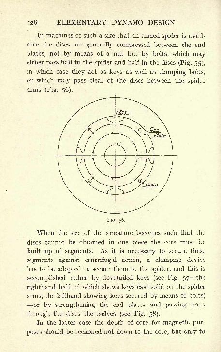
128 ELEMENTARY DYNAMO DESIGN
In machines of such a size that an armed spider is avail-
able the discs are generally compressed between the end
plates, not by means of a nut but by bolts, which mayeither pass half in the spider and half in the discs (Fig. 55),
in which case they act as keys as well as clamping bolts,
or which may pass clear of the discs between the spider
arms (Fig. 56).
FIG. 56.
When the size of the armature becomes such that the
discs cannot be obtained in one piece the core must be
built up of segments. As it is necessary to secure these
segments against centrifugal action, a clamping device
has to be adopted to secure them to the spider, and this is'
accomplished either by dovetailed keys (see Fig. 57 the
righthand half of which shows keys cast solid on the spider
arms, the lefthand showing keys secured by means of bolts)
or by strengthening the end plates and passing bolts
through the discs themselves (see Fig. 58).
In the latter case the depth of core for magnetic pur-
poses should be reckoned not down to the core, but only to
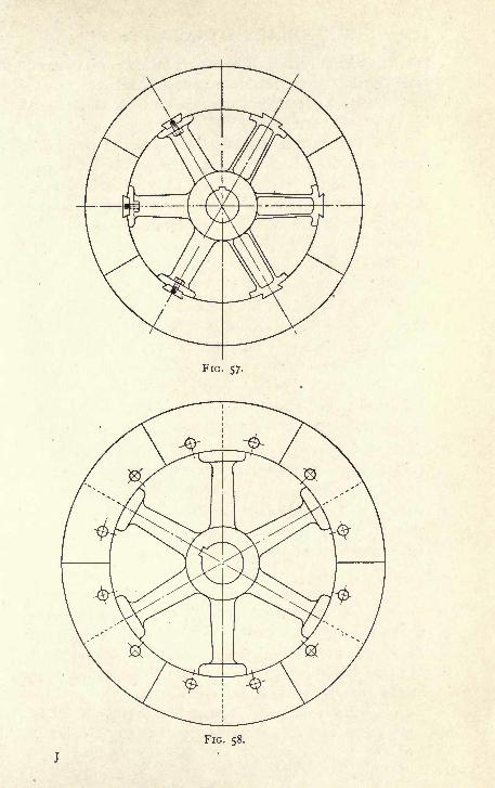
FIG. 57.
FIG. 58.
130 ELEMENTARY DYNAMO DESIGN
the top of the bolts. Of course in building up a core of
this description, the segments must break joint ;this re-
quires careful watching of the number of bolts used, and
of their position relatively to the slots.
4. Commutator Construction. One of the chief
mechanical difficulties occurring in the construction of a
dynamo is in the proper securing of the commutator parts.
The commutator consists of a copper cylinder built up of
comparatively narrow copper segments to which the arma-
ture windings are connected. Each of these segments
must be insulated from its neighbours, and from all me-
chanical supports. Nevertheless, the construction must
be absolutely rigid, as the slightest motion of any of the
segments or of the insulating material between them spoils
the cylindrical surface on which the brushes are running,
and the slightest want of truth is apt to cause sparking
at the brushes, which itself further spoils the surface, and,
therefore, becomes worse and worse as time goes on.
Unfortunately no insulating substance has any great
mechanical strength. In the best practice mica is the
only substance used for the insulation of commutators.
The copper segments are rolled to the proper taper, and
on one side of each segment there is fixed with shellac
varnish a sheet of mica of the same dimensions as the
commutator segment and about ^" thick.
The section of the segment is easily calculated from
the diameter of the commutator and the number of segments.
If for instance a commutator is required having an outside
diameter of 9", and consisting of 165 parts, the circum-
ference at the surface of the commutator will be 9 TT = 28-3",
and this divided by 165 gives for the width of each segment
at the top -171" ;this includes the thickness of insulation
between two segments. If this thickness be taken at
03", there is left for the copper a width of
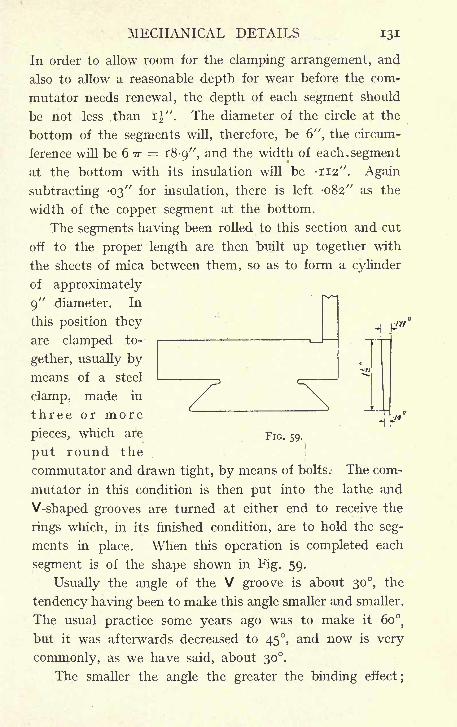
MECHANICAL DETAILS 131
In order to allow room for the clamping arrangement, and
also to allow a reasonable depth for wear before the com-
mutator needs renewal, the depth of each segment should
be not less than i". The diameter of the circle at the
bottom of the segments will, therefore, be 6", the circum-
ference will be 6 TT = 18-9", and the width of each. segment
at the bottom with its insulation will be -112". Again
subtracting -03" for insulation, there is left -082" as the
width of the copper segment at the bottom.
The segments having been rolled to this section and cut
off to the proper length are then built up together with
the sheets of mica between them, so as to form a cylinder
of approximately
9" diameter. In
this position they
are clamped to-
gether, usually bymeans of a steel
clamp, made in
threeormore -^
pieces, which are FIG. 59,
put round the
commutator and drawn tight, by means of bolts. The com-
mutator in this condition is then put into the lathe and
V-shaped grooves are turned at either end to receive the
rings which, in its finished condition, are to hold the seg-
ments in place. When this operation is completed each
segment is of the shape shown in Fig. 59.
Usually the angle of the V groove is about 30, the
tendency having been to make this angle smaller and smaller.
The usual practice some years ago was to make it 609
but it was afterwards decreased to 45, and now is very
commonly, as we have said, about 30.
The smaller the angle the greater the binding effect;
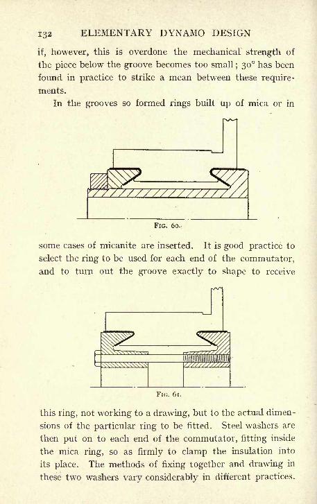
132 ELEMENTARY DYNAMO DESIGN
if, however, this is overdone the mechanical strength of
the piece below the groove becomes too small; 30 has been
found in practice to strike a mean between these require-
ments.
In the grooves so formed rings built up of mica or in
FIG. 60.,
some cases of micanite are inserted. It is good practice to
select the ring to be used for each end of the commutator,
and to turn out the groove exactly to shape to receive
FIG. 61.
this ring, not working to a drawing, but to the actual dimen-
sions of the particular ring to be fitted. Steel washers are
then put on to each end of the commutator, fitting inside
the mica ring, so as firmly to clamp the insulation into
its place. The methods of fixing together and drawing in
these two washers vary considerably in different practices.
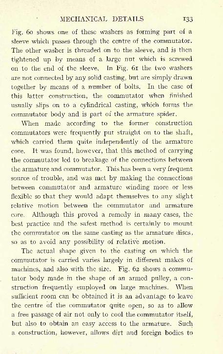
MECHANICAL DETAILS 133
Fig. 60 shows one of these washers as forming part of a
sleeve which passes through the centre of the commutator.
The other washer is threaded on to the sleeve, and is then
tightened up by means qf a large nut which is screwed
on to the end of the sleeve. In Fig. 61 the two washers
are not connected by any solid casting, but are simply drawn
together by means of a number of bolts. In the case of
this latter construction, the commutator when finished
usually slips on to a cylindrical casting, which forms the
commutator body and is part of the armature spider.
When made according to the former construction
commutators were frequently put straight on to the shaft,
which carried them quite independently of the armature
core. It was found, however, that this method of carrying
the commutator led to breakage of the connections between
the armature and commutator. This has been a very frequent
source of trouble, and was met by making the connections
between commutator and armature winding more or less
flexible so that they would adapt themselves to any slight
relative motion between the commutator and armature
core. Although this proved a remedy in many cases, the
best practice and the safest method is certainly to mount
the commutator on the same casting as the armature discs,
so as to avoid any possibility of relative motion.
The actual shape given to the casting on which the
commutator is carried varies largely in different makes of
machines, and also with the size. Fig. 62 shows a commu-
tator body made in the shape of an armed pulley, a con-
struction frequently employed on large machines. Whensufficient room can be obtained it is an advantage to leave
the centre of the commutator quite open, so as to allow
a free passage of air not only to cool the commutator itself,
but also to obtain an easy access to the armature. Such
a construction, however, allows dirt and foreign bodies to
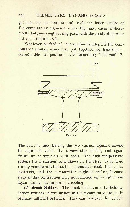
134 ELEMENTARY DYNAMO DESIGN
get into the commutator and reach the inner surface of
the commutator segments, where they may cause a short-
circuit between neighbouring parts with the result of burningout an armature coil.
Whatever method of construction is adopted the com-
mutator should, when first put together, be heated to a
considerable temperature, say something like 200 F.
FIG. 62.
The bolts or nuts drawing the two washers together should
be tightened whilst the commutator is hot, and again
drawn up at intervals as it cools. The high temperature
softens the insulation, and allows it, therefore, to be more
readily compressed, but as the commutator cools, the copper
contracts, and the commutator might, therefore, become
slack if this contraction were not followed up by tightening
again during the process of cooling.
5. Brush Holders. The brush holders used for holding
carbon brushes on the surface of the commutator are made
of many different patterns. They can, however, be divided
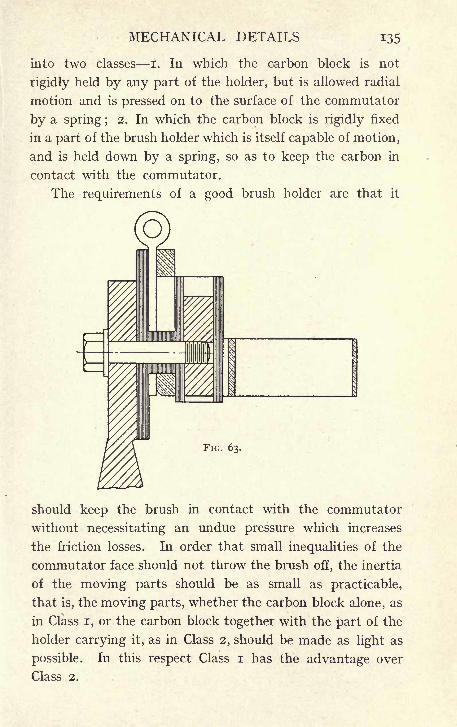
MECHANICAL DETAILS 135
into two classes I. In which the carbon block is not
rigidly held by any part of the holder, but is allowed radial
motion and is pressed on to the surface of the commutator
by a spring ;2. In which the carbon block is rigidly fixed
in a part of the brush holder which is itself capable of motion,
and is held down by a spring, so as to keep the carbon in
contact with the commutator.
The requirements of a good brush holder are that it
FIG. 63.
should keep the brush in contact with the commutator
without necessitating an undue pressure which increases
the friction losses. In order that small inequalities of the
commutator face should not throw the brush off, the inertia
of the moving parts should be as small as practicable,
that is, the moving parts, whether the carbon block alone, as
in Class I, or the carbon block together with the part of the
holder carrying it, as in Class 2, should be made as light as
possible. In this respect Class I has the advantage over
Class 2.

136 ELEMENTARY DYNAMO DESIGN
The brush should also be held in such a way that if it
be thrown off the commutator for an instant, it shall fall
back to exactly the same bearing. This necessitates that
the carbon in brush holders of Class I should work between
guides with a minimum of clearance, and in Class 2 that the
pivots carrying the brush arm should have a long bearing
surface so as to insure rigidity against side motion.
Again, the construction must be such as to insure that
FIG. 64.
there is no sticking, and that the carbons are absolutely
free radially to follow any irregularity of the commutator.
In addition, provision must be made to carry the current
through a positive connection to some fixed part of the
holder, and no reliance should be placed on moving contacts
such as the pivot in the case of a pivoted holder, or the
contact between carbon and the box in which it moves
in a holder of Class I. This is usually provided for by
fixing flexible copper wires on to the brush itself, and attach-
ing these to some fixed portion of the holder. When this
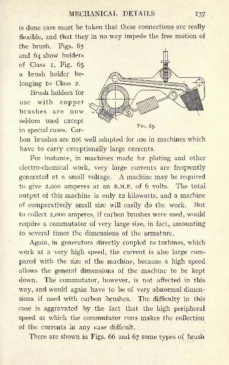
MECHANICAL DETAILS 137
is done care must be taken that these connections are really
flexible, and that they in no way impede the free motion of
the brush. Figs. 63
and 64 show holders
of Class I, Fig. 65
a brush holder be-
longing to Class 2.
Brush holders for
use with copperbrushes are nowseldom used exceptr
FIG. 65.in special cases. Car-
bon brushes are not well adapted for use in machines which
have to carry exceptionally large currents.
For instance, in machines made for plating and other
electro-chemical work, very large currents are frequently
generated at a small voltage. A machine may be required
to give 2,000 amperes at an E.M.F. of 6 volts. The total
output of this machine is only 12 kilowatts, and a machine
of comparatively small size will easily do the work. But
to collect 2,000 amperes, if carbon brushes were used, would
require a commutator of very large size, in fact, amountingto several times the dimensions of the armature.
Again, in generators directly coupled to turbines, which
work at a very high speed, the current is also large com-
pared with the size of the machine, because a high speed
allows the general dimensions of the machine to be kept
down. The commutator, however, is not affected in this
way, and would again have to be of very abnormal dimen-
sions if used with carbon brushes. The difficulty in this
case is aggravated by the fact that the high peripheral
speed at which the commutator runs makes the collection
of the currents in any case difficult.
There are shown in Figs. 66 and 67 some types of brush
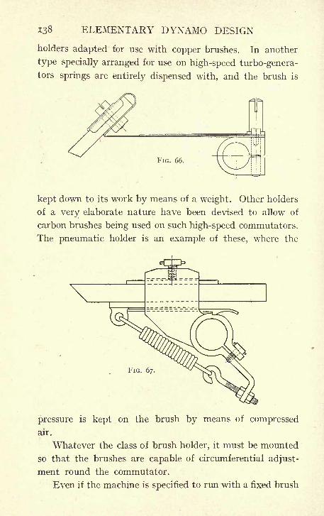
138 ELEMENTARY DYNAMO DESIGN
holders adapted for use with copper brushes. In another
type specially arranged for use on high-speed turbo-genera-
tors springs are entirely dispensed with, and the brush is
FIG. 66.
kept down to its work by means of a weight. Other holders
of a very elaborate nature have been devised to allow of
carbon brushes being used on such high-speed commutators.
The pneumatic holder is an example of these, where the
FIG. 67.
pressure is kept on the brush by means of compressed
air.
Whatever the class of brush holder, it must be mounted
so that the brushes are capable of circumferential adjust-
ment round the commutator.
Even if the machine is specified to run with a fixed brush

MECHANICAL DETAILS 139
position, it is necessary that the best brush position should
be found on test, and in order to enable this to be done
?^^^
FIG. 68.
conveniently the brush holders should be mounted on a
rocker. The rocker is a casting mounted on the bearing
pedestal and carrying all
the brushes;
it is usually
made in two halves bolted
together; by tightening
the bolts after the cor-
rect brush position has
been found further
motion of the brushes is
prevented (Fig. 68).
In large-size machines
the brush holders are
fixed to a large ring
carried by brackets from
the magnet yoke instead
of being mounted on the
pedestal (Fig. 69).
In the case of all large machines a hand wheel is provided
FIG. 69.
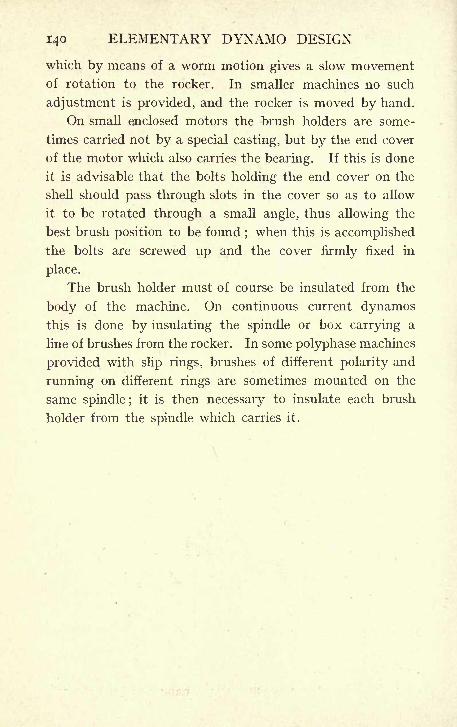
140 ELEMENTARY DYNAMO DESIGN
which by means of a worm motion gives a slow movementof rotation to the rocker. In smaller machines no such
adjustment is provided, and the rocker is moved by hand.
On small enclosed motors the brush holders are some-
times carried not by a special casting, but by the end cover
of the motor which also carries the bearing. If this is done
it is advisable that the bolts holding the end cover on the
shell should pass through slots in the cover so as to allow
it to be rotated through a small angle, thus allowing the
best brush position to be found ; when this is accomplished
the bolts are screwed up and the cover firmly fixed in
place.
The brush holder must of course be insulated from the
body of the machine. On continuous current dynamosthis is done by insulating the spindle or box carrying a
line of brushes from the rocker. In some polyphase machines
provided with slip rings, brushes of different polarity and
running on different rings are sometimes mounted on the
same spindle ;it is then necessary to insulate each brush
holder from the spindle which carries it.
CHAPTER VI
CONTINUOUS-CURRENT DYNAMOS AND MOTORS FOR SPECIAL
PURPOSES
DYNAMOS have at times to be designed to meet special
requirements which necessitate departure from the usual
lines of design. A few such cases will now be noticed.
1. High-Speed Generators. Since the steam turbine
has become of practical importance, special attention has
been directed to generators designed to run at a very
high speed. High speeds are necessary to give good
efficiency in the steam turbine, and it is not uncommon to
run as high as 3,000 revolutions per minute for outputs
up to, say, 3,000 H.P. Generators to be driven by such
turbines have to be coupled directly to the turbine and
must, therefore, run at the same speed.
The difficulties arising in the design of continuous-
current dynamos to run at such high velocities are chiefly
difficulties of commutation and mechanical difficulties due
to the centrifugal force at a high peripheral speed.
The reactance voltage of such machines is necessarily
high, because it is obvious that the armature should be
made of comparatively small diameter, and therefore of
comparatively great length in order to avoid dangerously
high peripheral speeds. In the case of alternators, the
magnets can be made the rotating part of the machine,
and their construction may be such as safely to allow of
comparatively high peripheral speeds ; but a continuous-
current armature, carrying conductors on its periphery
which must be secured against centrifugal forces, does not
141
142 ELEMENTARY DYNAMO DESIGN
lend itself to peripheral speeds greater than 10,000 to
15,000 ft. per minute as an outside limit. It is thus seen
that an armature running at, say, 3,000 revolutions per
minute, cannot have a diameter greater than about 18",
and if a large output is required, the armature must be
made of comparatively great length.
Thus if a generator is required to run at 3,000 revolu-
tions, and give an output of 2,000 kilowatts, the value of
2,000,000D, the watts per revolution, will be - = 670, the
3,000
corresponding d 2l is about 15,000, and the diameter must
not exceed 18", therefore / will be, say, 46".
Compare this with a machine to give 333 kilowatts
at 500 revolutions, the value of D and therefore of d 21 will
be the same, but the diameter can now be increased, and
the values of d and / may be taken at, say, 30" and 13 ". The
difference in the reactance voltages will be apparent on
substituting in the formula on page 8 1. In the first case the
pole area taking 4 poles will be : x -7 X 46 = 455
square inches, and the value of N working at a density of
7,500 lines per square centimeter in the air gap will be
455 x 6-45 X 7,500 = 22 X 10 6;
in the second case, taking
6 poles, the pole area will be ^- X -7 X 13 = 286 square
inches, and the corresponding value of N is 286 x 6-45
X 7,500 = 13-8 X io 6.
In each case there will be one turn only per commu-
tator part, and the reactance voltage will be
2,000,000 X 20 X I X TT X 46~
4 X 22 X IO 6p = -~
- = DO
333,000 x 20 x i x TT x 13and p = r^ = 3-25
6 x 13-8 x io 6
respectively.
SPECIAL DYNAMOS AND MOTORS 143
This value is very much too high in the case of the
high-speed machine to give satisfactory results, and it
is therefore usually found necessary in such machines to
employ some of the special commutating devices described
at the end of this chapter.
2. Variable - Speed Motors Speed Variations bySeries Resistance. Difficulties of the same nature arise in
the case of continuous-current motors which are required
to run at a variable speed. Variation in speed can be
readily obtained in two different ways. A resistance maybe introduced in the armature circuit : this reduces the
voltage at the brushes, and thus decreases the speed.
This method is frequently used in conjunction with series-
wound motors on such apparatus as cranes and for
driving vehicles, as, for instance, tramcars, and it is well
adapted to this purpose. It suffers, however, from two
serious disadvantages.
Firstly, it is extremely inefficient, as a large amount
of the power drawn from the mains is wasted in the re-
sistance. In fact, if it can be assumed that the torque
required by the driven apparatus is constant (this is approx-
imately true in many instances), the current drawn from
the mains is the same at whatever speed the motor is run.
If, for example, the apparatus is to be made to run at half
speed, sufficient resistance must be introduced to absorb
half the voltage. The current flowing through the motor
and resistance is the same as it was at full speed, but of
the watts drawn from the mains half only are used in the
motor, the other half are wasted in the resistance, and
the efficiency of the combination can therefore never rise
to as much as 50%.
Secondly, in addition to this very serious drawback, a
further one is found in the fact that the speed at which the
motor runs is dependent not only on the actual amount
144 ELEMENTARY DYNAMO DESIGN
of resistance in the circuit, but also on the current flowing
in that resistance, so that a change of load causes a cor-
responding change of speed unless suitable change is made
in the amount of resistance. For many purposes this is
a serious disadvantage, and as a matter of fact this method
of speed regulation is never used except in cases such as
those mentioned above, -where an attendant is constantly
at hand to regulate the speed at every instant as may be
required.
3. Speed Variation by Shunt Resistance. A second
method of speed control for a continuous-current motor
is applicable to shunt-wound or compound-wound motors,
and consists of introducing a resistance in series with the
shunt winding. Since the shunt current is only a small
percentage of the current flowing in the motor, the energy
lost in a shunt resistance is inconsiderable, and therefore
this method is greatly superior to the former one on the
score of efficiency.
In a shunt-wound motor for any given position of the
resistance switch, the speed will be approximately inde-
pendent of the load. The effect of introducing resistance
into the shunt circuit of a motor is of course to decrease
the current in this winding, therefore to decrease the number
of ampere-turns on the machine and consequently the total
magnetic flux. The back E.M.F. generated by the motor is
proportional to N and to the speed. On introducing resist-
ance, this back E.M.F. is diminished, since the value of N
is decreased. The E.M.F. applied to the terminals of the
motor is, however, constant, and if the back E.M.F. falls,
a greater current will flow through the armature. This
will cause it to accelerate, and the speed will increase
until the back E.M.F. is again brought up to a value
corresponding to the E.M.F. applied at the terminals. Anumerical example will make this clear.
SPECIAL DYNAMOS AND MOTORS 145
The motor designed in Chapter IV. normally runs at
600 revolutions per minute, and has a total magnetic flux
per pole (N) of 1-8 x io 6 lines. If resistance be intro-
duced in the shunt circuit the number of ampere-turns per
pole will be decreased. Assume that resistance is intro-
duced to such an amount as will reduce N to 1-2 X io 6
lines. The back E.M.F. generated will now be
660 x 4 X 1-2 X io 6 x 600 _ <.
60 x io 8
instead of
660 x 4 x 1-8 x io 6 x 600
60 x io= 471
(see formula on page 53).
The resistance of the armature circuit is 1-6 ohm,
and since the E.M.F. of the mains is 500 volts, there will
be available 500 318 = 182 volts, and the current will
beg-
= 115 amperes. The full-load current of the machine
is only 18 amperes, and the much greater torque due to
the increased current will cause the armature to accelerate
rapidly.
It should be noted that even if the change in the shunt
resistance is made suddenly the field strength will not adaptitself instantly to the new conditions. The change will be
gradual and acceleration will begin to take place as soon as
the current exceeds 18 amperes. By the time the field has
settled down to its new value the speed and therefore the
back E.M.F. will have increased, and a current of 115 ampereswill not actually flow in the armature. This figure merely
represents the highest limit which the current would attain
if the field strength could be varied instantaneously, and
the actual current will approach more or less nearly to
this upper limit according as the change of field strength
is less or more rapid.
K
146 ELEMENTARY DYNAMO DESIGN
If it may be assumed that the torque required by the
load is independent of the speed, 18 amperes will still be
required in the armature conductors to drive the load, and
acceleration will go on until the back E.M.F. again reaches
471 volts (since 18 X 1-6 = 29 volts are dropped in arma-
ture resistance and 500 29 = 471). With the weakened
field the speed required for this is given by the equation
R 471 x io 8
60~
4 x 1-2 x io 6 x 660"
(a simple modification of the equation on page 53).
.-. R = 14-5 x 60 = 870 revolutions per minute.
It is evident from the above that the motor will run at
its lowest speed when the full shunt current is allowed to
pass, and that the speed will increase as the resistance
is introduced into the shunt circuit. That is to say the
motor must be designed for, the lowest speed at which it
is intended to run it, and must, on that account, be con-
siderably larger than would be the case if it had been got
out for a high speed only. This fact is specially noticeable
in cases where the higher power is required at the higher
speed only and the power at the lower speed is considerably
reduced.
Take, for instance, a shunt - wound motor intended
to drive a fan at 1,200 revolutions per minute, the H.P.
required being io, and intended also to run at 600 revolutions
per minute when the necessary H.P. is reduced to 2. The
size needed for such a machine will be very nearly that of
a motor capable of giving not 2 H.P., but io H.P. at 600
revolutions per minute. The number of bars on the arma-
ture, and the number of magnetic lines per pole, must be
such as to give a speed of 600 revolutions. Nevertheless,
the bars must be large enough to carry safely the current
required for io H.P., since this current will be put through
when the fan is running at 1,200 revolutions, and this method,
SPECIAL DYNAMOS AND MOTORS 147
therefore, whilst much superior to regulation by series
resistance, has the disadvantage of requiring a larger motor,
and therefore entails an increased first cost.
Having settled the size of the motor, the difficulties
met with, in the design, are due to the fact that at the high
speed, when a large current is. taken by the motor, the
value of N is at its lowest. Inspection of the formula for
reactance voltage will show that the reactance voltage
varies inversely as the value of N, and if, for instance, this
value be made half of the maximum in order to obtain
double speed the reactance voltage will thereby also be
doubled. To keep this value within reasonable bounds, the
size of the motor must be still further increased, and although,
in a few instances, motors with even a larger speed variation
than 2 to I were put on the market, it was seldom considered
advisable to attempt even a 2 to I variation, because of the
largely increased size of motor required. Of recent years,
however, the introduction of commutating poles, one of
the special devices to be described later, has made it possible
to work with very high reactance voltages, and it is now
practicable to get speed variations of even 3 or 4 to I,
without prohibitive increase of size.
4. Series-Parallel Control.- When two motors are
used on the same load, as, for instance, the two motors
driving a tramcar, the method of varying the speed
known as the series-parallel control is often used. Acontroller or switch is used which alters the connection
of the motors to the mains so as to put them either in
series or in parallel with one another.
The motors are each designed to give normal speed at,
sav> 500 volts. When they are coupled in parallel across
the mains they will run at this speed, but when the con-
nections are altered so as to put the motors in series, each
will have on its terminal only 250 volts, instead of 500,
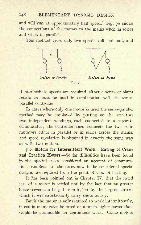
148 ELEMENTARY DYNAMO DESIGN
and will run at approximately half speed. Fig. 70 shows
the connections of the motors to the mains when in series
and when in parallel.
This method gives only two speeds, full and half, and
tnoton tn Parallel friton <n
FIG. 70.
if intermediate speeds are required, either a series or shunt
resistance must be used in combination with the series-
parallel controller.
In cases where only one motor is used the series-parallel
method may be employed by putting on the armature
two independent windings, each connected to a separate
commutator;the controller then connects the two com-
mutators either in parallel or in series across the mains,
and speed regulation is obtained in exactly the same wayas with two motors. .
5. Motors for Intermittent Work. Rating of Crane
and Traction Motors. So far difficulties have been found
in the special cases considered on account of commuta-
tion troubles. In the cases now to be considered special
designs are required from the point of view of heating,
It has been pointed out in Chapter IV. that the rated
H.P. of a motor is settled not by the fact that no greater
horse-power can be got from it, but by the largest current
which it will satisfactorily carry continuously.
But if the motor is only required to work intermittently,
it can in many cases be rated at a much higher power than
would be permissible for continuous work. Crane motors
SPECIAL DYNAMOS AND MOTORS 149
and traction motors are typical cases of machines designed
for intermittent work. The hoisting motor fitted on, say,
a lo-ton travelling crane, will not be at work for more
than a small portion of the time. If the crane is fitted in a
general engineering shop, it will probably have to hoist
10 tons only at very rare intervals, and will be'
engaged*
generally, handling very much smaller weights. Although
it must therefore be capable of sufficient H.P. to deal with
the heaviest weight, it need only be capable of doing this
maximum H.P. without sparking ;the question of the
temperature-rise is comparatively unimportant.
The same argument is true of a tramcar motor which,
whilst it must be capable of a considerable effort for a
short period in order to accelerate the car on the stiffest
gradient, is usually running at a very much smaller out-
put. Such motors are therefore made very much smaller
than motors for general work required to give the same
H.P., that is to say, a motor which would ordinarily be
called a 10 H.P. motor may, for crane or traction work,
be rated at 15 or even 20 H.P., and provided care is
taken that its constants are such as to allow it to give
this higher power without sparking, the results are quite
satisfactory.
The question of the temperature-rise allowable in such
cases has not yet been altogether standardised in Great
Britain. The rating frequently used for tramcar motors
was imported from the United States, and is to the effect
that the motor on test shall not rise more than loo degrees
Centigrade when run for one hour at its rated full load.
This, of course, does not mean that the temperature in
actual practice would ever rise to this amount, which would
cause deterioration of the insulating material, but that
it has been found as a matter of usage that motors which
do not exceed this rise on a test of one hour's duration
150 ELEMENTARY DYNAMO DESIGN
do not get dangerously hot under the actual working con-
ditions on a day's run.
A similar standard has been discussed for use with
crane motors, but the conditions under which different
cranes are employed are more dissimilar than is the case
with different traction systems. It has, therefore, been
proposed by some manufacturers that the rating of the
motor should be based on lines as nearly as possible similar
to the working conditions. They have thus proposed
that the motor should be rated at such a power that, when
run on test for a specified number of minutes, say two, four,
or six minutes out of every twelve, it shall not rise more
than 70 F., however long the process be continued. This
method, whilst theoretically good, means a tedious and
troublesome test, and, probably for this reason, has not
been very generally adopted. Crane-makers more usually
specify a test of either half or one hour's duration at full
rated load, the temperature-rise at the end of this run not
to exceed either 70 or 100 F.
If these are taken as the standard crane ratings at
present generally used in Great Britain, it will be seen that
for any given H.P. required, any one of four different sizes
of motors may be used according to the specification. The
smallest will be the half-hour rating with 100 F. rise, whilst
the largest will be the one rated for one hour at only 70 F.
rise. Which of these four ratings should be used in any
special case depends upon the conditions under which the
crane will be generally worked.
6. Comnrntating1 Poles. Amongst other devices which
have been brought out for the purpose of improving the
commutation, both in motors and generators, that known
as commutating poles or interpoles is now coming largely
into use. In order to effect the reversal in the armature
coil which is short-circuited by the brush, an external
SPECIAL DYNAMOS AND MOTORS 151
E.M.F. is required which, if it is to effect a perfect reversal
at all loads without change of brush position, should be
proportional to the load the machine is carrying. In an
ordinary machine this E.M.F. may be supplied by the
magnetic field in the interpolar space.
Unfortunately, as has already been pointed out, it is
necessary, in order to get into a field having the right polarity
to effect reversal, to move the brushes forward in the case
of a generator, backward in the case of a motor. In both
instances, the motion is towards that pole tip which is
weakened by the reaction of armature, and since the
weakening effect of the cross turns depends on the current
the armature is carrying, this field will at any one given
point get weaker as the load increases, that is, the field
will be weakest just at the time when the strongest re-
versing force is required. It will therefore be necessary
to move the brushes nearer the pole so as to get into a
region of stronger field as the load increases. As it is
quite usual to specify that a machine shall work from
no-load to full load without change of brush position,
this method of compensating for the weakened field at
full load is not available, and in a machine which is
not supplied with any special commutating device, it is
necessary that the reactance voltage be kept so low that
good commutation is obtained without the assistance of
an external reversing field. The brushes can then be
placed on or about the neutral axis, and remain there
for any load.
A very low reactance voltage is only obtained at con-
siderable cost in the construction of the machine. The
number of commutator parts must be abnormally large, and
the machine has not infrequently to be of larger diameter
and shorter length than would be dictated by considerations
of cost of manufacture. In the case of motors where a large

152 ELEMENTARY DYNAMO DESIGN
variation in speed is required, by means of shunt regulation,
the problem becomes still more difficult, and an increase
of speed of more than 100% is practically impossible on
an ordinary machine.
It has already been pointed out that a series-wound
motor is superior to a shunt - wound in respect of com-
mutation, from the fact that the strength of the whole
magnetic field, and therefore also of the fringe in which
commutation is taking place increases with increase of
load.
A commutating pole consists of a magnet core and pole
shoe fixed in the gap between two main poles (see Fig.
71), the winding of which is connected in series with the
armature, and the object of this pole is to provide a magnetic
field, such that the motion of the conductors under the
brush will generate an E.M.F. of a direction and strength
suitable to effect sparkless reversal even with a high value
of the reactance voltage. The winding of the reversing
pole being in series
Yoke ^_^ ( -^-^comnatattif pok with the armature, the
strength of field pro-
duced will be propor-
tional to the load, and
thus, if the right pro-
portion of turns is
FIG. 71. found to give a goodreversal at any one
value *of the current, the same relative strength of field
will be present at all other values of the current, and the
commutation will be sparkless at all loads without any
change of brush position. The only limit to this is the
saturation of the steel in the auxiliary pole. When this
becomes saturated, increased current does not produce a
correspondingly increased field, and the armature reaction
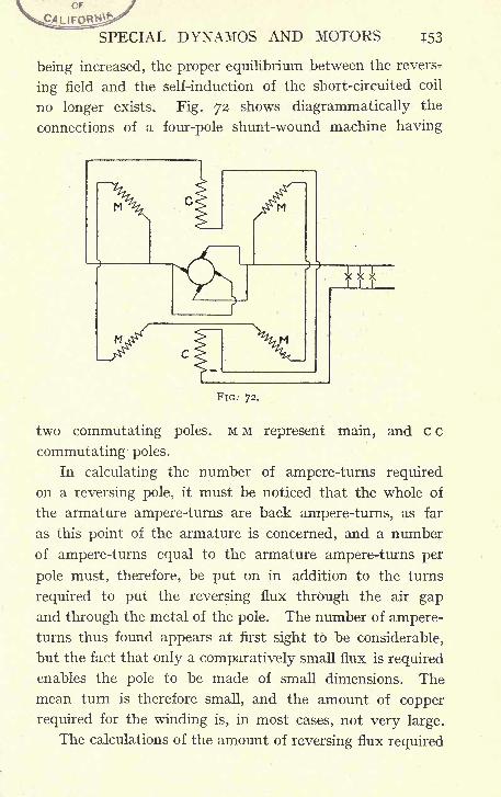
OF
SPECIAL DYNAMOS AND MOTORS T53
being increased, the proper equilibrium between the revers-r
ing field and the self-induction of the short-circuited coil
no longer exists. Fig. 72 shows diagrammatically the
connections of a four-pole shunt-wound machine having
FIG. 72.
two commutating poles. M M represent main, and c c
commutating poles.
In calculating the number of ampere-turns required
on a reversing pole, it must be noticed that the whole of
the armature ampere-turns are back ampere-turns, as far
as this point of the armature is concerned, and a number
of ampere-turns equal to the armature ampere-turns per
pole must, therefore, be put on in addition to the turns
required to put the reversing flux through the air gapand through the metal of the pole. The number of ampere-turns thus found appears at first sight to be considerable,
but the fact that only a comparatively small flux is required
enables the pole to be made of small dimensions. The
mean turn is therefore small, and the amount of copper
required for the winding is, in most cases, not very large.
The calculations of the amount of reversing flux required
154 ELEMENTARY DYNAMO DESIGN
are based on the assumption that the reactance voltage
of the machine is known and that an E.M.F. sufficient
exactly to counterbalance the mean value of the reactance
voltage should be generated in the short-circuited coil by the
reversing flux. This flux may be obtained in several ways.
The area of the auxiliary pole face may be varied, and the
magnetic induction in the air-gap may also be varied.
It is well to work at a fairly high density ;the number
of ampere-turns required to overcome the gap reluctance
is in any case not a very large proportion compared with
the number of ampere-turns required to overcome the
armature back turns. The area of the pole face can be
suitably modified;the width of the auxiliary pole should
be not less than one slot and one tooth, the length measured
parallel to the shaft may be cut down to any desired extent
provided the required area is obtained. Whilst in an
ordinary machine the reactance voltage cannot be allowed
to exceed two volts if good commutation is to be obtained
with a fixed brush position, with suitable interpoles the
reactance voltage may be allowed to increase up to 10
or 12 volts without inconvenience.
The adoption of reversing poles is very effective for
working satisfactorily with such high reactance voltages,
and is therefore extremely useful for special cases such
as were noticed at the beginning of this chapter, where it
is impossible to get out a design which will keep the reactance
voltage down to the usual limits. Also, in some cases where
a design on the usual lines could be quite readily got out,
it is possible by the use of reversing poles considerably to
lessen the depth of the air gap, and therefore the weight of
copper required, and thus in various ways to cheapen the
machine. But, however well proved the advantage of
commutating poles may be in these cases where special
commutating devices are necessary, it is doubtful whether it
SPECIAL DYNAMOS AND MOTORS 155
is sound policy to use them, whether absolutely necessary
or not, throughout a line of machines many of which
could quite well be designed without their use.
A numerical example will now be given, showing the
calculations required for finding the necessary flux and
the necessary number of ampere-turns on the commutat-
ing pole. The reactance voltage is first calculated by
means of the formula on page 81.
If it be required, for instance, to increase the speed' of
the motor designed in Chapter IV. from 600 to 1,800 bymeans of shunt resistance, this will require that the field
strength should be reduced to one - third ; namely, to
N = 600,000, and the reactance voltage instead of being
_5ooxi8x4X2oxvrx6_ ^p :
4 x 1-8 x io tt
as given on page 96, will become :
_ 500 x 18 x 4 x 20 X7rx6 _p ''
4 x -6 x io 6
This is the maximum value of the reactance voltage on the
assumption that the variation of strength in the coil under
the brush is represented by a sine curve ;on this assumption
the mean value of the reactance voltage will be -636 X 5-5
= 3*5 (Page X64), and it will be necessary that the commu-
tating pole should give such a flux as will generate in the
short-circuited coil an E.M.F. of 3*5 volts.
Either two or four commutating poles may be used;a
little consideration of the winding diagrams given in
Chapter II. will show that even if only two commutating
poles are used, all the coils which are undergoing commu-
tation will have some of their conductors under one or
other of these poles. If two poles only are used, the number
of conductors belonging to one coil which will be in a
commutating field at one instant will be four, since there
are four turns per coil. It is required to generate in the
156 ELEMENTARY DYNAMO DESIGN
coil an E.M.F. of 3-5 volts, each conductor must therefore
have induced in it an E.M.F. of about -9 volts, that is, -9 x io 8
c.G.s. units of E.M.F., that is, it must cut lines of magnetic
force at the rate of -9 x io 8 lines per second. The peripheral
speed of the armature is 12 TT x 600 = 22,700 inches per
22 VOO X 2'^A.
minute, which is equal to -^ ^-2 = 960 centimeters
per second. If, then, the magnetic field be such as to give
9 x io 8
-7 94,000 lines in each centimeter, measured cir-
cumferentially, the rate of cutting lines will be that required
to give 3-5 volts in the short-circuited coil.
If the pole shoe of the commutating coil be made 12
centimeters long, measured parallel to the shaft, the magnetic
density in the air gap will be = 7,800. This is a
suitable density to work at. The width of the pole should
be such that the coil remains in the field during the whole
time of short circuit, say ij" in this case. From which it
follows that the pole shoe should be ij" wide, measured
circumferentially, and 12 cms. = 4^" long, measured parallel
to the shaft. If four commutating poles were used instead
of two only, each could be made half the length, since each
pole would be required to generate only half the E.M.F.
The total flux from one pole will be found by multiplying
the area of the shoe in square centimeters by 7,800, the value
of B. The area == 12 x 3-2 = 38-4 square centimeters,
and the total flux N = 38-4 X 7,800 = 298,000 lines.
The magnet core must be made of sufficient section to
carry these lines, and a large coefficient of leakage must
be allowed for, because whilst the leakage paths are not
materially different from the leakage paths of the main
poles in their sectional area, the total flux from the com-
mutating pole is very much smaller, and therefore a much
SPECIAL DYNAMOS AND MOTORS 157
larger proportion of the total magnetic lines will pass
along the leakage paths. A coefficient of 2 may be used;
the number of lines in the magnet coil will then be 298,000
X 2 = 596,000, and working at about 13,000 lines per
square centimeter, the area of the steel must be13,000
= 46 square centimeters, or 7 square inches. A round
magnet core 3" diameter will give very nearly this area.
The number of ampere-turns to be provided on each
pole are equal to the armature ampere-turns per pole added
to the ampere-turns required to put the magnetic flux
through the air gap. The number of wires on the armature
is 1,320, the number of turns = 660, and the number2
of turns per pole- - = 165, and each turn carries at full
load 9 amperes ;the armature ampere-turns per pole are there-
fore 1,485, say 1,500, and if the depth of the air gap under
the commutating pole is made -^g", the same as under the
main poles, the ampere-turns required will be -475 x 7,800
X -8 2,900, say altogether 4,500 ampere-turns, and
at full load 18 amperes is the current carried by the motor.
The number of turns on each commutating pole must there-
fore be ,> = 250. The two commutating poles will
be connected in series with one another and with the
armature.
That the commutating pole winding should be connected
in series with the armature is, as already pointed out, the
essential feature of this device, as it insures the value of
the commutating field being proportional to the current it
has to reverse. Commutating poles are also referred to
as interpoles, auxiliary poles, and reversing poles.
7. Compensating Coils. Another device with a similar
158 ELEMENTARY DYNAMO DESIGN
object consists of compensating coils connected in series
with the armature, and let into slots in the main pole
faces. They are so connected as to oppose the armature
reaction. These coils cause the reversing flux at the tip
of the main pole face to remain comparatively unchangedin value under considerable fluctuations of armature cur-
rent, and in this way assist in obtaining good commutation
without change of brush position. Whilst the commutat-
ing poles produce an entirely new field in which the re-
versal is carried out, the object of the compensating coils
is to maintain the fringe of the main field at such a
strength as is suitable for sparkless reversal.
In order to obtain perfect compensation, the number of
conductors carried across eaten pole face must be such as
to give a number of ampere-turns equal to the armature
ampere-turns per pole; if this number be provided, the
armature reaction will be entirely compensated for, the
current in each armature conductor will be neutralised byan equal current flowing in the opposite direction in the
compensating coils, and the field strength will therefore
not vary, whatever the load on the machine. It is evident,
however, that a considerable number of watts will be lost
in such a winding, and not only will the efficiency suffer,
but the heating will be increased, unless the dimensions
of the machine are altered so as to provide increased cooling
surface.
8. Sayer's Commutator Coils. In both the above in-
stances it will be seen that the object sought is attained
by introducing an E.M.F. in the short-circuited coil bymeans of a magnetic field. In the commutating device
known as Sayer's coils, the same object is attained by pro-
viding on the armature special conductors, which are
brought into play only during reversal.
The main winding of Sayer's armature is exactly similar
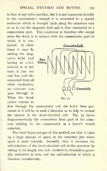
SPECIAL DYNAMOS AND MOTORS 159
to that of any other machine, but it is not connected directly
to the commutator;instead it is connected to a special
conductor which is brought back along the armature core
so as to cut the magnetic field and is then connected to a
commutator part. This conductor is therefore idle except
when the brush is in contact with the commutator part to
which it is con-
nected. At other ^mmu/a*/C*t^_
times it may be
cutting the mag-netic field and
having an E.M.F.
induced in it, but
since it has one
end free, and dis-
connected from all
other conductors,
no current can
pass through it.
When the brush
causes current to
flow through the commutator coil, the E.M.F. then gen-
erated in it will be in such a direction as to help to reverse
the current in the short-circuited coil. Fig. 73 shows
diagrammatically the connections from part of the arma-
ture winding to the commutator in a Sayer's wound
armature.
The chief disadvantages of this method are that it takes
up a large amount of space on the armature just where
space is most valuable. Secondly, that it increases the
self-induction of the short-circuited coil of the armature by
adding to its length two new conductors, themselves gener-
ally embedded in slots, and the self-induction of which is
therefore considerable.
FIG. 73.
l6o ELEMENTARY DYNAMO DESIGN
The one great advantage it possesses is that the direc-
tion of the commutator coils can be made such as to cause
the reversal to take place under the leading pole tip in the
case of a generator, and the trailing tip in the case of a
motor. That is to say, Sayer's winding can be arranged
so that the brushes are brought backwards in the case of
a generator, and forward in the case of a motor, instead of
the opposite arrangement as in an ordinary winding. The
result of this is not only that the reversal takes place in
both"cases . under the strengthened instead of under the
Weakened tip/ but it also has the effect of changing the
armature ampere-turns from back ampere-turns to forward
ampere-turns. Thus in both cases the armature ampere-
turns will strengthen the field as the load increases, instead
of weakening it, and a generator wound on this principle
tends to compound and maintain a fixed E.M.F. under all
fluctuations of load.
In practice it was generally found that this effect was
not sufficient to keep the voltage constant with increasing
load, and that a few series turns had to be added.
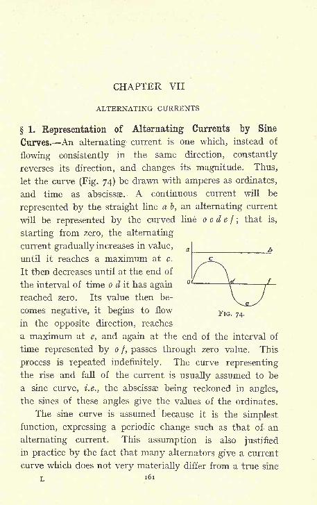
CHAPTER VII
ALTERNATING CURRENTS
1. Representation of Alternating Currents by Sine
Curves. An alternating current is one which, instead of
flowing consistently in the same direction, constantly
reverses its direction, and changes its magnitude. Thus,
let the curve (Fig. 74) be drawn with amperes as ordinates,
and time as abscissae. A continuous current will be
represented by the straight line a b, an alternating current
will be represented by the curved line o c d e f ;that is,
starting from zero, the alternating
current gradually increases in value,
until it reaches a maximum at c.
It then decreases until at the end of
the interval of time o d it has again
reached zero. Its value then be-
comes negative, it begins to flow FlG<
in the opposite direction, reaches
a maximum at e, and again at the end of the interval of
time represented by o /, passes through zero value. This
process is repeated indefinitely. The curve representing
the rise and fall of the current is usually assumed to be
a sine curve, i.e., the abscissae being reckoned in angles,
the sines of these angles give the values of the ordinates.
The sine curve is assumed because it is the simplest
function, expressing a periodic change such as that of an
alternating current. This assumption is also justified
in practice by the fact that many alternators give a current
curve which does not very materially differ from a true sine
L l61
i6s ELEMENTARY DYNAMO DESIGN
curve, and actual experimental facts, therefore, justify
the adoption of a function which is necessary in order to
make mathematical treatment of alternating- current
phenomena possible. In problems where greater accuracy
is needed, the mathematical fact that any periodic function
whatever can be broken up into components, each of which
is a true sine curve, can always be made use of. Going back
to the simple assumption that an alternating current or
an alternating E.M.F. may be represented by a sine curve
the number of times per second that a current goes through
a complete cycle is called the periodicity of the current, and
is generally represented by the symbol ru . The periodicities
in use in Great Britain at present are usually between 50
periods per second and 25 periods per second, represented
by 50 cv> and 25 ru respectively. A current of n periods
per second is therefore one which goes through a complete
cycle n times in one second and, if T represent the time
taken for one complete cycle T, is evidently equal to -.
The current will have passed through a complete cycle
and reached zero at the time T the sine curve has passed
through a complete cycle, and reached zero when the
angle is 360 or in circular measure 2 TT;the scale of time
must therefore be such that T = 2 TT, and on such a scale
any time t from the beginning of the cycle will correspond
to the angle-
. If c be the maximum value of the cur-
rent, the value of the corresponding ordinate is c sin
and this, therefore, is the instantaneous value of the cur-
rent at the time t. But T = -, and substituting this in
the above expression, c sin 2 TT n t is obtained as the value
of the current at the time t.
ALTERNATING CURRENTS 163
This is the final expression for instantaneous values
of the current supposed to follow a sine law, and all that
has been said as to current is of course equally true of
E.M.F. curves. This expression is, however, somewhat
lengthy, and it is not uncommon to simplify it by writing
the symbol p instead of the expression 27rn, the instan-
taneous value of the current is then c sin pt, and p has
by some writers been called the pulsation of the current.
This simplified form may always be used remembering
that p is merely an abbreviation for 2irn.
2. Mean Value and R.M.S. Value of an Alternating
Current. In engineering formulae, it is not usually the
instantaneous value of the current or E.M.F. which is re-
quired to be dealt with;
it is the average effect, and there
are two values which are of importance. The mean value
of the current over a half period can be found by plot-
ting the current curve, finding its area by means of a
planimeter, and dividing by the length of the base.
The process is exactly similar to that of finding the
mean pressure from a steam-engine indicator diagram,
and it gives the mean value of the current. If this
process be carried out on a sine curve it will be found
that the mean value is -636 times the maximum value.
By means of a simple integration it can easily be shown
2that the mean value of a sine curve is - times the maximum
7T
value. If A be the maximum value y = A sin x will be
/Vthe equation to the curve, and A sin % dx will be
J o
the area enclosed by the curve and the axis of % between
values of x = TT, and x = o, and - A sin x d x will
o
7"
A7T
164 ELEMENTARY DYNAMO DESIGN
therefore be the mean value, but sin x dx = COSTT +J o
cos o = 2, .-. the mean value of a sine curve, the maximum2 2
value of which is A, is - X A and - is equal to -636, nearly.7T 7T
The heating effect, however, of a current, depends
not upon the value of the current, but on the value of the
square of the current ; for instance, in a lamp of resistance
a), the watts absorbed are = c 2&>. If, therefore, it is
desired to compare continuous and alternating values of
current as regards their heating effect, it is the value of
the current squared which must be considered. This can
be done by plotting from the sine curve, another derived
curve, the ordinates of which are obtained by squaring
the sines. If the area of this curve be now taken, and divided
by the base, the mean value of the current squared is
obtained ; taking the square root of this gives what is known
as the root mean square current. This is usually denoted
by the letters R.M.S. By actually plotting a curve and
integrating it, it will be found that the value of this R.M.S.
current is -707 times the maximum value of the current.
It is easity shown mathematically that it is = - times
the maximum value, and this is approximately equal to -707.
The same reasoning as used above for the sine curve
shows the mean square value of a sine curve, the maxi-
mum value of which is A, to be
r r :vI . , i 9 7 x sm x cos x- A 2 sin 2 * dx and sm 2 xdx = -
>
7T 2
Jo J.'. the mean square value = - A 2 and the square root of
this is . A.
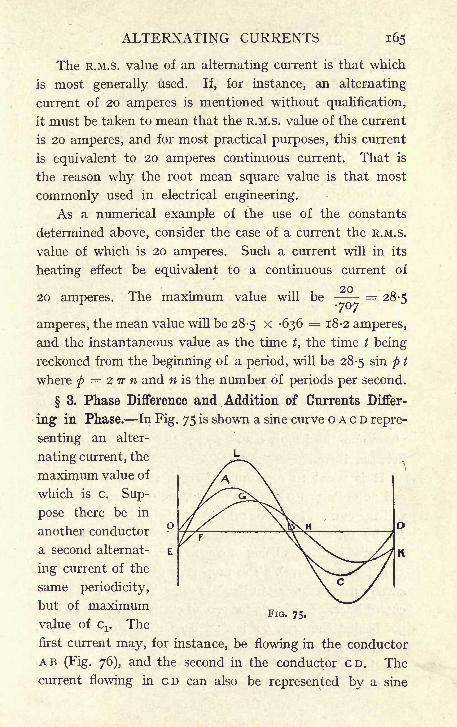
ALTERNATING CURRENTS 165
The R.M.S. value of an alternating current is that which
is most generally used. If, for instance, an alternating
current of 20 amperes is mentioned without qualification,
it must be taken to mean that the R.M.S. value of the current
is 20 amperes, and for most practical purposes, this current
is equivalent to 20 amperes continuous current. That is
the reason why the root mean square value is that most
commonly used in electrical engineering.
As a numerical example of the use of the constants
determined above, consider the case of a current the R.M.S.
value of which is 20 amperes. Such a current will in its
heating effect be equivalent to a continuous current of
2020 amperes. The maximum value will be
70728-5
amperes, the mean value will be 28-5 x -636 = 18-2 amperes,
and the instantaneous value as the time t, the time t being
reckoned from the beginning of a period, will be 28-5 sin p t
where p = 2 TT n and n is the number of periods per second.
3. Phase Difference and Addition of Currents Differ-
ing in Phase. In Fig. 75 is shown a sine curve o A c D repre-
senting an alter-
nating current, the
maximum value of
which is c. Sup-
pose there be in
another conductoro
a second alternat-
ing current of the
same periodicity,
but of maximumvalue of cx . The
first current may, for instance, be flowing in the conductor
AB (Fig. 76), and the second in the conductor CD. Thecurrent flowing in CD can also be represented by a sine
FIG. 75.
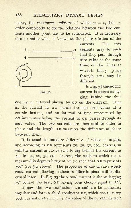
i66 ELEMENTARY DYNAMO DESIGN
FIG. 76,
curve, the maximum ordinate of which is = C1?but in
order completely to fix the relations between the two cur-
rents another point has to be considered. It is necessary
also to notice what is known as the phase relation of the
currents. The two
C currents may be such
that they pass through
zero value at the same
time, or the times at
which they pass
through zero may be
different.
In Fig. 75 the second
current is shown as lag-
ging behind the first
one by an interval shown by OF on the diagram. That
is, the current in A B passes through zero value at a
certain instant, and an interval of time represented byo F intervenes before the current in c D passes through its
zero value. The two currents are then said to differ in
phase and the length o F measures the difference of phase
between them.
It is usual to measure difference of phase in angles,
and according as o F represents 10, 20, 30, etc., degrees, so
will the current in c D be said to lag behind the current in
AB by 10, 20, 30; etc., degrees, the scale to which OF is
measured in degrees being of course such that o D represents
360 (see 2 above). The properties of the circuits which
cause currents flowing in them to differ in phase will be dis-
cussed later. In Fig. 75 the second current is shown lagging
30 behind the first, o F having been chosen equal to 30.
If now the two conductors AB and CD be connected
together and form a third conductor B F, which has to carry
both currents, what will be the value of the current in B F ?
ALTERNATING CURRENTS 167
If continuous current were being dealt with it is well
known that the current in B F would be the sum of the
currents in A B and c D; the same is true of .alternating
currents, provided instantaneous values are taken.
At any instant the current in B F will be the sum of the
currents in AB and CD, but it does not follow from this
that the maximum current in B F will be the sum of
the maximum currents in AB and CD. Such will only
be the case if the maxima in the two branches occur
at the same time, that is, if the two currents are in phase ;
if there is any difference of phase the maxima will occur
at different times, and the maximum current in B F will be
less than the combined maxima in AB and CD.
By adding together the ordinates of the sine curves
o A c D and E F G H K a third curve is obtained giving the in-
stantaneous values of the current in BF. The curve so
obtained E L B K is also a sine curve having the same
periodicity as the other two and having a maximum
value, say D, which is less than c + c 1.
The process can be carried out by trigonometry instead
of geometrically. The instantaneous value of the current
in A B will be c sin p t and the instantaneous value of
the current, in CD cx sin (pt + 30), and by adding these
together the required result will be obtained.
c sin p t -f- Cj sin (p t + 30)= c sin p t + Cj cos 30 sin p t -f- Cj sin 30 cos p t
= c + c sin pt + iCi cos ft.
Let M = c H--- cx and N = cl3
then the above expression becomes
M sin f t + N cos p t.
NFurther, let < be such an angle that = tan
M
i68 ELEMENTARY DYNAMO DESIGN
now M sin p t + N cos p t = x/ M 2-f N 2 sin (p t + <f>),
for x/M 2 + N 2 sin (t + 0) = x/ M 2 + N 2
(sin p t cos</>
+ cos/tf sin <^>) (I.).
But since = tan ^>,
N _ sin<f> _ sin
<f>
M cos</> ^/i sin 2^'
.-. N 2(i sin 2
$) = M 2 sin 2<,
... (M2 + N 2
)sin2
(/)=N 2
,
/. sin 2(f>=
.'. sin<j>=
M 2 + N 2 '
N
X/M 2 + N 2
MIn the same way it can be shown that cos 6 = ,
V M 2 + N 2
Substituting these values in (I.)
+ N 2 sin (pt
sin
= M sin p t + N cos p t.
The value of the current in B F is therefore
xM 2 + N 2 sin (p t + <),
and substituting the values of M and N this becomes
V/(c +^ C3)
2 + (J Cl )2 sin
+ xc Cj. sin (pt + <j>)where tan
c+^3 Ci2C+ 3X/C,'
Which means that the current flowing in B F has a
maximum value equal to Vc 2 + c12 + \/3Cc1 and lags
behind the current in A B by an angle <j>,of which the tangent
G!is =--
j= ,
i2 c + V 3 Ci
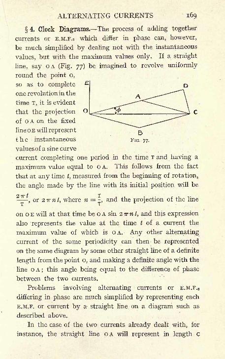
ALTERNATING CURRENTS 169
4. Clock Diagrams. The process of adding together
currents or E.M.F.S which differ in phase can, however,
be much simplified by dealing not with the instantaneous
values, but with the maximum values only. If a straight
line, say OA (Fig. 77) be imagined to revolve uniformly
round the point o,
so as to complete
one revolution in the
time T, it is evident
that the projection O
of OA on the fixed
line oE will represent
the instantaneous FIG. 77.
values of a sine curve
current completing one period in the time T and having a
maximum value equal to o A. This follows from the fact
that at any time t, measured from the beginning of rotation,
the angle made by the line with its initial position will be
'-tor ZTrnt, where n = -, and the projection of the line
on o E will at that time be o A sin 2 TT n t, and this expression
also represents the value at the time t of a current the
maximum value of which is OA. Any other alternating
current of the same periodicity can then be represented
on the same diagram by some other straight line of a definite
length from the point o, and making a definite angle with the
line OA; this angle being equal to the difference of phase
between the two currents.
Problems involving alternating currents or E.M.F.S
differing in phase are much simplified by representing each
E.M.F. or current by a straight line on a diagram such as
described above.
In the case of the two currents already dealt with, for
instance, the straight line OA will represent in length c
70 ELEMENTARY DYNAMO DESIGN
the maximum value of one current. OB must be drawn
to represent in length cl5 the maximum value of the other
current, and it must be drawn making an angle of 30
with o A, 30 being the difference of phase v
between the
two currents. OA and OB are known as vectors, that is
to say, not only their length is significant, but also their
direction. The sum of two vectors is obtained by complet-
ing the parallelogram of which they form the sides, and
drawing the diagonal through o, which then represents the
resultant vector. A familiar example of this is the addi-
tion of forces by the parallelogram of forces. If this be
done in Fig. 77, o c is obtained as the sum of the two cur-
rents, and it is useful exercise to compare the results of
Fig. 77 and Fig. 75. By actually rotating the parallelo-
gram round the point o, it will be readily seen that the
projections of OA, OB, and oc, on the line OE, will, when
plotted out, give respectively the curves OACD, EFGHK,and E L B K, and on the other hand by solving the triangle
OAC in Fig. 77, the length of oc can be found as
follows :
O C 2 = O A 2 + A C 2 2 O A, O C COS O A C,
but OAC is equal to 180 AOJB, that is to 180 30;.-. COS OAC = COS 30,.-. o c 2 = o A 2 + A c 2
-j- 2 o A ox; cos 30
and cos 30 =J-^-.
... o C 2 = O A 2-|- A C 2
-f- */~3 O A O C,
Or OC=X/OA 2-J-AC
2 -fx/30A OC,
and since o A represents c in magnitude, and A c represents
cx this result is equivalent to that obtained by adding
instantaneous values on page 168.
Again, producing o A to D and drawing c D perpendicular
to o D, the angle D A c = 30 ;
and tan <> =
ALTERNATING CURRENTS 171
.-. CD = AC sin 30, AD = AC cos 30,
C D
O A + A D
AC sin 30 -j-AC
OA+ACCOS30 OA + \/3 AC2
2 c + \/ 3 G!*
which again corresponds with the value for tan(f>
found
on page 168.t
The representation of alternating currents or E.M.F.S
in this way by vectors gives what is known as the clock
diagram. On the clock diagram is indicated not only the
magnitude of the currents dealt with, but also their phase
relations, and in this way the most complicated problems
may be solved. It should be noticed that the lines OA,
o B and o c, for instance, strictly represent in the diagram
maximum values only, but since the R.M.S. value or the mean
value bears a constant ratio to the maximum value, the
clock diagram may be taken to represent not maximum, but
R.M.S. or mean value;
it is simply a question of working
to a different scale. E.M.F.'S can, of course, be dealt with in
exactly the same way, and it is not unusual to draw clock
diagrams in which both E.M.F.'S and currents are combined,
and their phase relations to one another shown.
5. Self-induction, Reactance and Impedance, As
a simple instance of the use of clock diagrams, take a circuit
of known resistance (o. If an alternating E.M.F. be applied
to the terminals, the maximum value of which is E, and the
number of periods per second n, it is required to find the
current which will flow through the circuit. If continuous
current were being dealt with, the current would be equal
to -, but with alternating currents the results are modified
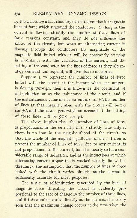
172 ELEMENTARY DYNAMO DESIGN
by the well-known fact that any current gives rise to magneticlines of force which surround the conductor. So long as the
current is flowing steadily the number of these lines of
force remains constant, and they do not influence the
E.M.F. of the circuit, but when an alternating current is
flowing through the conductors the magnitude of the
magnetic field linked with it will be constantly varyingin accordance with the variation of the current, and the
cutting of the conductor by the lines of force as they altern-
ately contract and expand, will give rise to an E.M.F.
Suppose L to represent the number of lines of force
linked with the circuit at the instant when one ampereis flowing through, then L is known as the coefficient of
self-induction or as the inductance of the circuit, and if
the instantaneous value of the current is c sin p t, the number
of lines at that instant linked with the circuit will be L c
sin pt, and the E.M.F. generated on account of the cutting
of these lines will be pLC cos pt.
The above implies that the number of lines of force
is proportional to the current ;this is strictly true only if
there is no iron in the neighbourhood of the circuit, so
that the whole of the magnetic path lies in air;
if iron is
present the number of lines of force, due to any current, is
not proportional to the current, but it is nearly so for a con-
siderable range of induction, and as the inductions at which
alternating current apparatus is worked usually lie within
this range, the assumption that the number of lines of force
linked with the circuit varies directly as the current is
sufficiently accurate for most purposes.
The E.M.F. of self-induction generated by the lines of
magnetic force threading the circuit is evidently pro-
portional to the rate of change in the number of these lines,
and if this number varies directly as the current, it is easily
seen that the maximum change occurs at the time when the
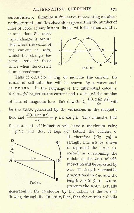
ALTERNATING CURRENTS 173
current is zero. Examine a sine curve representing an alter-
nating current, and therefore also representing the number of
lines of force at any instant linked with the circuit, and it
is seen that the most
rapid change is occur-
ring when the value of
the current is zero,
whilst the change be-
comes" zero at those
times when the current
is at a maximum. ;
:
Thus if OABCD in Fig. 78 indicate the current, the
E.M.F. of self-induction will be shown by a curve such
as E F G H K. In the language of the differential calculus,
if c sin p t .expresses the current and L c sin p t the number
v X j.- r -i MirVl d(LCSmpt) .,,
of lines of magnetic force linked with it,-
,^
willct t
be the E.M.F. generated by the variations in the magnetic
FIG. 78.
flux and -j-= p L c cos p t. This indicates that
the E.M.F. of self-induction will have a maximum value
= p L c, and that it lags 90 behind the current c.
If, therefore (Fig. 79), a
straight line AB be drawn
to represent the E.M.F. ab-
sorbed in overcoming the
resistance, the E.M.F. of self-
induction will be repeated byA D . The length A B must be
proportional to c &>, and the
length A D to p L c. A D re-
presents the E.M.F. actually
generated in the conductor by the action of the current
flowing through 'it.
~
In order, then, that the current c should
FIG'. 79.
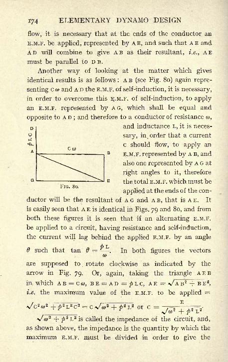
o
174 ELEMENTARY DYNAMO DESIGN
flow, it is necessary that at the ends of the conductor an
E.M.F. be applied, represented by AE, and such that AE and
AD will combine to give AB as their resultant, i.e., AE
must be parallel to D B.
Another way of looking at the matter which gives
identical results is as follows : A B (see Fig. 80) again repre-
senting c a) and A D the E.M.F. of self-induction, it is necessary,
in order to overcome this E.M.F. of self-induction, to apply
an E.M.F. represented by AG, which shall be equal and
opposite to A D;and therefore to a conductor of resistance &>,
D and inductance L, it is neces-
sary, in, order that a current
c should flow, to apply an
E.M.F. represented by A B, and
also one represented by A G at
right angles to it, therefore
the total E.M.F. which must be
applied at the ends of the con-
ductor will be the resultant of A G and A B, that is A E. It
is easily seen that A E is identical in Figs. 79 and 80, and from
both these figures it is seen that if an alternating E.M.F.
be applied to a circuit, having resistance and self-induction,
the current will lag behind the applied E.M.F. by an angle
such that tan =. In both figures the vectors
CO
are supposed to rotate clockwise as indicated by the
arrow in Fig. 79. Or, again, taking the triangle AEB
in which A B = ceo, BE = AD =^>L c, AE= v A B 2 + BE 2
,
i.e. the maximum value of the E.M.F. to be applied=
= c x a> + )L or c =
xo) 2 + p* L 2is called the impedance of the circuit, and,
as shown above, the impedance is the quantity by which the
maximum E.M.F. must be divided in order to give the
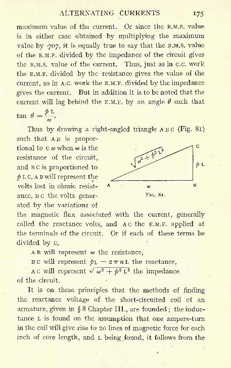
ALTERNATING CURRENTS 175
maximum value of the current. Or since the R.M.S. value
is in either case obtained by multiplying the maximum
value by -707, it is equally true to say that the R.M.S. value
of the E.M.F. divided by the impedance of the circuit gives
the R.M.S. value of the current. Thus, just as in c.c. work
the E.M.F. divided by the resistance gives the value of the
current, so in A.C. work the E.M.F. divided by the impedance
gives the current. But in addition it is to be noted that the
current will lag behind the E.M.F. by an angle such that
tan = -Lft)
Thus by drawing a right-angled triangle ABC (Fig. 81)
such that AB is propor-
tional to c Q) when G> is the
resistance of the circuit,
and B c is proportioned to *^ ^^ **L
p L c, A B will represent the
volts lost in ohmic resist- A w B
ance, BC the volts gener-FlG - 8l -
ated by the variations of
the magnetic flux associated with the current, generally
called the reactance volts, and AC the E.M.F. applied at
the terminals of the circuit. Or if each of these terms be
divided by c,
AB will represent w the resistance,
B c will represent pL = 2 TT n L the reactance,
AC will represent \/ CD* + <p2 L 2 the impedance
of the circuit.
It is on these principles that the methods of finding
the reactance voltage of the short-circuited coil of an
armature, given in 8 Chapter III., are founded;the induc-
tance L is found on the assumption that one ampere-turnin the coil will give rise to 20 lines of magnetic force for each
inch of core length, and L being found, it follows from the
176 ELEMENTARY DYNAMO DESIGN
above that the reactance of the circuit is 2 TT n L and the
reactance voltage is 2 IT n L c.
This is true only on the assumption that the current
in the short-circuited coil follows during reversal a sine
curve;this assumption is probably far removed from what
actually happens, but it is made as being the only workable
hypothesis, and it should be pointed out that the calculated
reactance voltage is used as a rule only to compare new
designs with others which have already been tried, so that
it is the comparative value of the reactance voltage in
different machines rather than its absolute value in anyone case which is useful, and if all cases are worked out on
the same assumption the comparative value of the results
may be valuable even if the assumption is not very strictly
justified.
6. The Power Factor. In continuous-current work-
ing, the power electrically given out by a generator or
absorbed by any lamp or other apparatus is obtained quite
simply by multiplying the volts at the terminals by the
amperes ;this gives watts which are the direct measure
of the rate at which power is given out or absorbed. In
the case of alternating currents, the. result of multiplying
R.M.S. volts by R.M.S. amperes gives the watts only in the
special case when the E.M.F. and the current are in phase.
Generally speaking, these will differ in phase by a certain
amount, say by the angle 6. The angle 6 is, as has been
seen, called the angle of lag or of lead, and in order to obtain
the watts a third factor must be introduced.
If E is the R.M.S. value of the E.M.F. at the terminals
of a generator, for instance, and c is the R.M.S. value
of the current, and the current differs in phase from the
E.M.F. by an angle 6, then the watts given out by the gen-
erator are equal to EC cos 6. For this reason cos 8 is
known as the power factor of the circuit. The product
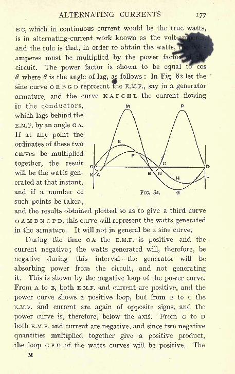
ALTERNATING CURRENTS 177
E c, which in continuous current would be the true watts,
is in alternating-current work known as the volt-
and the rule is that, in order to obtain the watts,
amperes must be multiplied by the power factoi
circuit. The power factor is shown to be equal tb~ cos
6 where is the angle of lag, as follows : In Fig. 82 let the
sine curve o E B G D represent the E.M.F., say in a generator
armature, and the curve K A F c H L the current flowing
in the conductors,
which lags behind the
E.M.F. by an angle o A.
If at any point the
ordinates of these two
curves be multiplied
together, the result
will be the watts gen-
erated at that instant,
and if a number of
such points be taken,
and the results obtained plotted so as to give a third curve
OAMBNCPD, this curve will represent the watts generated
in the armature. It will not in general be a sine curve.
During the time OA the E.M.F. is positive and the
current negative; the watts generated will, therefore, be
negative during this interval the generator will be
absorbing power from the circuit, and not generating
it. This is shown by the negative loop of the power curve.
From A to B, both E.M.F. and current are positive, and the
power curve shows, a positive loop, but from B to c the
E.M.F. and current are again of opposite signs, and the
power curve is, therefore, below the axis. From c to D
both E.M.F. and current are negative, and since two negative
quantities multiplied together give a positive product,
the loop c P D of the watts curves will be positive. The
M
FIG. 82.
178 ELEMENTARY DYNAMO DESIGN
watts generated will, therefore, be constantly varying
in value, and will sometimes be negative ;the mean value
of the watts generated will, however, be the area enclosed
by th,e'. curve OAMBNCPD (reckoning areas above the
line positive, and those below negative) divided by the
length o D.
If E be the maximum value of the E.M.F., and c that
of the current, the instantaneous values of E.M.F. will be
E sin p t, and of the current c sin (p t + 6). Where o A
represents the angle 6, if the curves are plotted to scale,
and the power curve derived from them by taking the pro-
ducts of corresponding ordinates as ordinates be also
plotted, the area of. the latter curve can be taken bymeans of a plammiter, and the area divided by the
length o D will be the mean watts generated. This will
. , CECOS0C E -
be found equal to - = -== x -=- X cos 6, and2 *J 2 *J 2
f ~F
-7= are the R.M.S. values of the current andx/2 x/2E.M.F. respectively. This result is arrived at immedi-
ately by integrating ;the area of the watts curve
E sin p t x c sin (p t -f- 0) d t, and the mean value of
the watts is accordingly E sin p t x c sin (p t+0) d t,
"J o
, . , . C E COS 6which gives the above result-- .
It is evident that as the phase difference increases,
the mean watts generated decrease, the area of the loops
above the axis gradually diminishes, and the area
of the negative loops below the line is increasing,
until when the phase difference becomes 90, the watts
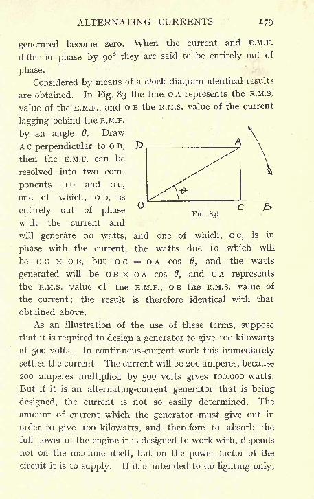
ALTERNATING CURRENTS 179
FIG. 831
generated become zero. When the current and E.M.F.
differ in phase by 90 they are said to be entirely out of
phase.
Considered by means of a clock diagram identical results
are obtained. In Fig. 83 the line o A represents the R.M.S,
value of the E.M.F., and o B the R.M.S. value of the current
lagging behind the E.M.F.
by an angle 6. Draw
A c perpendicular to o B,
then the E.M.F. can be
resolved into two com-
ponents o D and o c,
one of which, o D, is
entirely out of phase
with the current and
will generate no watts, and one of which, o c, is in
phase with the current, the watts due to which will
be o c X o B, but o c = o A cos 0, and the watts
generated will be OB x OA cos 6, and OA represents
the R.M.S. value of the E.M.F., OB the R.M.S. value of
the current; the result is therefore identical with that
obtained above.
As an illustration of the use of these terms, suppose
that it is required to design a generator to give loo kilowatts
at 500 volts. In continuous-current work this immediately
settles the current. The current will be 200 amperes, because
200 amperes multiplied by 500 volts gives 100,000 watts.
But if it is an alternating-current generator that is being
designed, the current is not so easily determined. The
amount of current which the generator must give out in
order to give loo kilowatts, and therefore to absorb the
full power of the engine it is designed to work with, dependsnot on the machine itself, but on the power factor of the
circuit it is to supply. If it is intended to do lighting only,
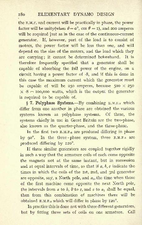
x8o ELEMENTARY DYNAMO DESIGN
the E.M.F. and current will be practically in phase, the powerfactor will be unity(when 6= o, cos =
i), and 200 amperes
will be required just as in the case of the continuous-current
generator. If, however, part of the load is to consist of
motors, the power factor will be less than one, and will
depend on the size of the motors, and the load which they
are carrying; it cannot be determined beforehand. It is
therefore frequently specified that a generator shall be
capable of absorbing the full power of the engine, on a
circuit having a power factor of -8, and if this is done in
this case the maximum current which the generator must
be capable of will be 250 amperes, because 500 X 250
X -8 = 100,000 watts, which is the output the generator
is required to be capable of.
7. Polyphase Systems. By combining E.M.F.S .which
differ from one another in phase are obtained the various
systems known as polyphase systems. Of these, the
systems chiefly in use in Great Britain are the two-phase,
also known as the quarter-phase, and the three-phase.
In the first two E.M.F.S are produced differing in phase
by 90. In the three-phase system, three E.M.F.S are
produced differing by 120.
If three similar generators are coupled together rigidly
in such a way that the armature coils of each come opposite
the magnets not at the same instant, but in succession
and at equal intervals of time, so that if a, b, c indicate the
times in which the coils of the 1st, 2nd, and 3rd generator
are opposite, say, a North pole, and a1} the time when those
of the first machine come opposite the next North pole,
the intervals from a to b, 6v to c, and c to a\ shall be equal,
then from this combination of machines there will be
obtained E.M.F.S which will differ in phase by 120.
In practice this is done not with three different generators,
but by fitting three sets of coils on one armature. Call
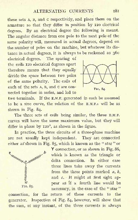
ALTERNATING CURRENTS 181
these sets A, B, and c respectively, and place them on the
armature so that they differ in position by 120 electrical
degrees. By an electrical degree the following is meant.
The angular distance from one pole to the next pole of the
same polarity will, measured in actual degrees, depend on
the number of poles on the machine, but whatever its dis-
tance in actual degrees, it is always to be reckoned as 360
electrical degrees. The spacing of
the coils 120 electrical degrees apart
therefore means that they equally
divide the space between two poles
of the same polarity. The coils of
each of the sets A, B, and c are con-r IG. 54-
nected together in series, and led to
two terminals. If the E.M.F. generated in each be assumed
to be a sine curve, the relation of the E.M.F.S will be as
shown in Fig. 84.
The three sets of coils being similar, the three E.M.F.
curves will have the same maximum value, but they will
differ in phase by 120, as shown in the figure.
In practice, the three circuits of a three-phase machine
are not usually kept independent. They are connected
either as' shown in Fig. 85, which is known as the " star"or
Y connection, or as shown in Fig. 86,
which is known as the triangle or
delta connection. In either case
three lines take away the currents
from the three points marked a, b,
and c. It might at first sight ap-
pear as if a fourth line would be"Fro 8c
necessary, in the case of the "star
"
connection, for the return of these currents to the
generator. Inspection of Fig. 84, however, will show that
the sum, at any instant, of the three currents is always
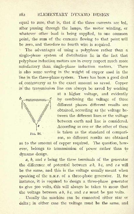
182 ELEMENTARY DYNAMO DESIGN
equal to zero, that is, that if the three currents are led,
after passing through the lamps, the motor winding, or
whatever other load is being supplied, to one common
point, the sum of the currents flowing to that point will
be zero, and therefore no fourth wire is required.
The advantages of using a polyphase rather than a
single-phase system of distribution lie in the fact that
polyphase induction motors are in every respect much more
satisfactory than single-phase induction motors. There
is also some saving in the weight of copper used in the
line in the three-phase system. There has been a good deal
of. controversy as to the exact amount so saved. Copperin the transmission line can always be saved by working
at a higher voltage, and evidently
by combining the voltage of three
different phases different results are
obtained, according as the voltage be-
tween the different lines or the voltage
between earth and line is considered.
According as one or the other of these
FlG
'
86 is taken as the standard of compari-
son, so different results are obtained
as to the amount of copper required. The question, how-
ever, belongs to transmission of power rather than to
dynamo design.
a, b, and c being the three terminals of the generator
the difference of potential between a 5, b c, and c a will
be the same, and this is the voltage usually meant when
speaking of the E.M.F. of a three-phase generator. If, for
instance, it is required to design a three-phase generator
to give 500 volts, this will always be taken to mean that
the voltage between ab, be, and c a must be 500 volts.
Usually the machine can be connected either star or
delta; in either case the voltage must be the same, and
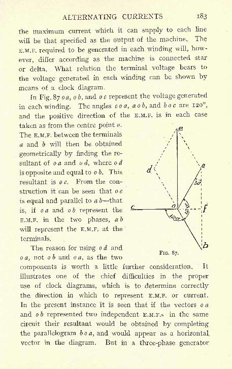
ALTERNATING CURRENTS 183
the maximum current which it can supply to each line
will be that specified as the output of the machine. The
E.M.F. required to be generated in each winding will, how-
ever, differ according as the machine is connected star
or delta. What relation the terminal voltage bears to
the voltage generated in each winding can be shown by
means of a clock diagram.
In Fig. 87 oa, o b, and a c represent the voltage generated
in each winding. The angles coa, aob, and bo c are 120,
and the positive direction of the E.M.F. is in each case
taken as from the centre point o.
The E.M.F. between the terminals
a and b will then be obtained
geometrically by finding the re-
sultant of o a and o d, where o d
is opposite and equal to o b. This
resultant is o e. From the con-
struction it can be seen that o e
is equal and parallel to a b that
is, if oa and ob represent the
E.M.F. in the two phases, ab
will represent the E.M.F. at the
terminals.
The reason for using o d and
o a, not o b and o a, as the two
components is worth a little further consideration. It
illustrates one of the chief difficulties in the proper
use of clock diagrams, which is to determine correctly
the direction in which to represent E.M.F. or current.
In the present instance it is seen that if the vectors o a
and ob represented two independent E.M.F.S in the same
circuit their resultant would be obtained by completing
the parallelogram boa, and would appear as a horizontal
vector in the diagram. But in a three-phase generator
FIG. 87.
184 ELEMENTARY DYNAMO DESIGN
there are two circuits connected at the point o, and the
convention has been established that the direction from
o to a and o to b shall be considered the positive direction
in each respectively.
It is therefore obvious that in passing through the
windings from terminal a to terminal b, the passage along
one winding, ob, is in the positive and along the other,
ao, in the negative direction, and that it is therefore not the
sum, but the difference, of the two E.M.F.S which will be
measured between a and b. One of the vectors must,
therefore, be turned through 180 before completing the
parallelogram. Which of the two shall be reversed in this
way is a matter of indifference. If o b is reversed, as has
been done in the diagram, it means that from b to a is reck-
oned the positive direction in measuring voltage at the
terminals, and if o a had been reversed the resultant vector
would have been of the same length, but in the opposite
direction;from a to b would then have been the positive
direction for measuring voltage. Whichever of these con-
ventions is adopted it must be carried through consistently
in dealing with the other phases, but is otherwise immaterial.
From the construction, the angles at a and b are each
equal to 30. Draw o f perpendicular to a b, then a f equals
o a cos 30, and a b is equal to 2 a /, therefore a b is equal
to 2 o a cos 30 and cos 30 is equal to , therefore a b
equals x/ 3 o a, and this is for practical purposes sufficiently
nearly equal to 1-73 o a. It may, therefore, be said that in the
case of a star-connected generator the E.M.F. at the terminals
is equal to 173 times the E.M.F. generated in each phase.
The current flowing in each line, however, must evidently
be the same current as is flowing in the phase winding;
one phase only is connected to each terminal, and there
is no other winding supplying current to the line.
ALTERNATING CURRENTS 185
If a delta connection be used the cases are reversed.
The E.M.F. between the terminals a and b is evidently
equal to the E.M.F. generated in the winding ab (see Fig.
86), whilst the current flowing into the line at b is the
vectors sum of the currents flowing in the winding a b and
the winding b c. Exactly the same construction which has
been used for the E.M.F. will show that this current is equal
to 173 times the current in each phase.
To make this clear by a numerical example, suppose it
is required to build a generator to give 500 volts at its
terminals, and to supply 100 amperes per line. If this
is wound "star," the winding of each phase will have to be
suitable for giving = 290 volts, and will have to be of
sufficient section to carry 100 amperes. If, on the other hand,
the windings are connected "delta," each winding will have
to have a sufficient number of turns to give 500 volts,
but the section need only be capable of carrying-
= 58 amperes. The same arguments apply to the motors
or to groups of lamps to be supplied from the generator.
The windings of the motors or the groups of lamps maybe connected either star or delta, and the same rules as to
combining the currents or E.M.F.S will apply.
These statements are true, however, only when the
system is balanced, that is to say, when the three phases
are equally loaded and equal current is taken from each.
If the whole load consists of motors, this condition is ful-
filled or approximately so. The winding of each phaseof the motors is supposed to be exactly similar, and anywant of balance which may occur will be slight, and due to
accidental differences in the process of manufacture. If
lighting is also done by the generator, an attempt is generally
made to balance the lamps by putting equal numbers on
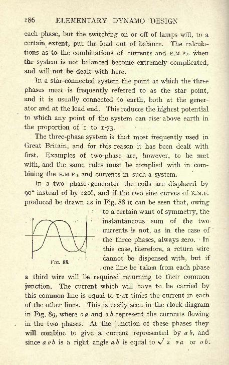
186 ELEMENTARY DYNAMO DESIGN
each phase, but the switching on or off of lamps will, to a
certain extent, put the load out of balance. The calcula-
tions as to the combinations of currents and E.M.F.S whenthe system is not balanced become extremely complicated,and will not be dealt with here.
In a star-connected system the point at which the three
phases meet is frequently referred to as the star point,
and it is usually connected to earth, both at the gener-ator and at the load end. This reduces the highest potentialto which any point of the system can rise above earth in
the proportion of i to 173.
The three-phase system is that most frequently used in
Great Britain, and for this reason it has been dealt with
first. Examples of two-phase are, however, to be met
with, and the same rules must be complied with in com-
bining the E.M.F.S and currents in such a system.
In a two -phase generator the coils are displaced by
90 instead of by 120, and if the two sine curves of E.M.F.
produced be drawn as in Fig. 88 it can be seen that, owingto a certain want of symmetry, the
instantaneous sum of the two
currents is not, as in the case of
the three phases, always zero. In
this case, therefore, a return wire
cannot be dispensed with, but ifr IG. oo. _ <
one line be taken from each phase
a third wire will be required returning to their common
junction. The current which will have to be carried bythis common line is equal to 1-41 times the current in each
of the other lines. This is easily seen in the clock diagram
in Fig. 89, where o a and o b represent the currents flowing
in the two phases. At the junction of these phases they
will combine to give a current represented by a b, and
since a ob is a right angle ab is equal to */ 2 oa or o b.
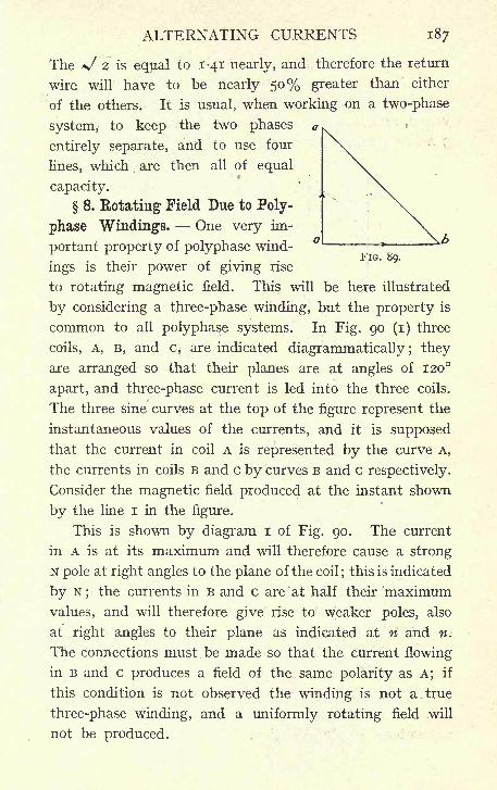
ALTERNATING CURRENTS 187
The x/ 2 is equal to 1-41 nearly, and therefore the return
wire will have to be nearly 50% greater than either
of the others. It is usual, when working on a two-phase
system, to keep the two phases
entirely separate, and to use four
lines, which are then all of equal
capacity.
8. Rotating Field Due to Poly-
phase Windings. One very im-
portant property of polyphase wind-. . FIG. 89.
ings is their power of giving rise
to rotating magnetic field, This will be here illustrated
by considering a three-phase winding, but the property is
common to all polyphase systems. In Fig. 90 (i) three
coils, A, B, and c, are indicated diagrammatically ; they
are arranged so that their planes are at angles of 120
apart, and three-phase current is led into the three coils.
The three sine curves at the top of the figure represent the
instantaneous values of the currents, and it is supposed
that the current in coil A is represented by the curve A,
the currents in coils B and c by curves B and c respectively.
Consider the magnetic field produced at the instant shown
by the line I in the figure.
This is shown by diagram I of Fig. 90. The current
in A is at its maximum and will therefore cause a strong
N pole at right angles to the plane of the coil;this is indicated
by N; the currents in B and c are at half their 'maximum
values, and will therefore give rise to weaker poles, also
at right angles to their plane as indicated at n and n.
The connections must be made so that the current flowing
in B and c produces a field of the same polarity as A; if
this condition is not observed the winding is not a true
three-phase winding, and a uniformly rotating field will
not be produced.
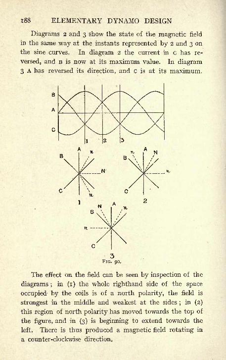
188 ELEMENTARY DYNAMO DESIGN
Diagrams 2 and 3 show the state of the magnetic field
in the same way at the instants represented by 2 and 3 on
the sine curves. In diagram 2 the current in c has re-
versed, and B is now at its maximum value. In diagram
3 A has reversed its direction, and c is at its maximum.
The effect on the field can be seen by inspection of the
diagrams ;in (l) the whole righthand side of the space
occupied by the coils is of a north polarity, the field is
strongest in the middle and weakest at the sides;
in (2)
this region of north polarity has moved towards the top of
the figure, and in (3) is beginning to extend towards the
left. There is thus produced a magnetic field rotating in
a counter-clockwise direction.
ALTERNATING CURRENTS 189
Although for simplicity the north poles only have been
indicated, there is of course a corresponding south pole
directly opposite each. Of the fields created by the three
coils, only the centre line has been indicated, but it is
obvious that the fields will overlap and strengthen one
another in the region between N and n, whilst outside
this region the field is due to one of the coils only.
As a matter of fact, the magnetic field, if not disturbed
by the unequal distribution of iron parts of the circuit,
will be represented by a sine curve having its maximumat N.
Obviously, when the currents have gone through one
complete period, the state of matters will be exactly as
shown in (i), that is, the sine wave of magnetic flux will
have travelled once round the circle during the time
occupied by one period of the current. The coils A, B,
and c form a two-pole winding, but the same reasoning
can be extended to any number of pairs of poles. If there
are more than two poles, the field will not complete one-
revolution in the time of one period of the current, but
will only pass through twice the pole pitch ; i.e., in the time
that the current completes one period, the magnetic field,
rotates through 360 electrical degrees. By altering the
connections to two of the coils so that the current shown
by curve B flows in coil c and vice versa, the field will be
made .to rotate clockwise instead of counter-clockwise.
This is easily seen by drawing the diagrams for positions
I, 2, and 3 over again with the altered relation of currents
and coils. This fact is useful in practice, as it enables-
polyphase induction motors to be run in the reverse direc-
tion by merely changing the connections of their windingsto the system of supply.
9. Calculation of E.M.P. in an Alternator Breadth
Coefficient. In calculating the E.M.F. generated in a c.c^
190 ELEMENTARY DYNAMO DESIGN
*D
machine the formula E x io 8 = z p N ^ was used (seeoo
Chapter III.), where z is the number of bars in series, P
the number of poles, and R the revolutions per minute.
This formula is true, however, only of the mean value
of the E.M.F. generated; different bars will have a different
E.M.F. generated in them, according to their position in
the field, but it is evident that since there are altogether
PN lines of magnetic force entering the armature, and a
60bar makes one revolution in - -
seconds, it will in thatR
time have cut PN bars, and therefore its average rate of
"D
cutting lines must be P N ^- .
oo
The effect of the commutator is to arrange that at any in-
stant bars situated at all points of the armature are connected
together so that their E.M.F.S add together in such a waythat the E.M.F. at the brushes is obtained by multiplying
the mean volts in each bar by the number of bars in series.
In the case of alternating-current machines, there is
no commutator to take automatically the average of the
E.M.F. generated at different points of the field, and it
is therefore necessary to consider the rate at which con-
ductors cut lines of force in such different positions.
Returning to the simple loop of wire rotated in a uniform
two-pole field, made use of in Chapter II., in Fig. 95 let
A B represent a section of the loop and imagine it turned
through 90 so as to be in that position where it
encloses the whole of the lines of magnetic force supposedto be uniformly distributed. Then, when the coil has moved
through an angle 6 the number of lines enclosed is obviouslyOT^ O*R
X N;but = cos 6, and the number of lines is thus
J* cos 0.
ALTERNATING CURRENTS 191
If n is the number of revolutions per second, trie coil
will have passed through an angle 2 TT in -second, or
an angle 2 TT n in one second, and therefore the angle
passed through in any time will be 2 TT nt. Therefore at
the time t the number of lines of force enclosed by the
coil will be N cos 2 IT nt, and as seen in 5 Of this chapter
the rate of change of N cos 2 TT n t is 2 IT n N sin 2 TT n t.
If the coil consists of T turns the E.M.F. generated will
be 2 TT n T N sin 2 TT n t.
The following values are thus obtained-
E (max. value) = 2 irn T N = 6-28 n T N
E (R.M.S. value) = -707 x 2 TT n x N = 4-4 n T N
E (mean value) = "636 x 2wn rrN = 4 n T'
N.
In each case, if E is in volts it must be multiplied by to 8
to bring it to C.G.S. units.
Note that the last formula, that for the mean value,
corresponds to the formula for the E.M.F. of a continuous-
current machine;
for n being the number of revolutions
per second in a two-pole field also represents the periodi-
city, and the periodicity divided by the number of pairs of
Ppoles, i.e., by
- = revolutions per second.
2 R PR.-. n X - = TT-. ... n =
P 60* 60 X 2*
and, again, the number of turns, T = J- the number of bars,
2.-. T = -
substituting in E x io 8 = 4 n T N
PR zEXI = 4 x SlTi x2XN '
R= P z- Z N,60
which is identical with the formula given above for con^
tinuous current.
A further correction has to be made in the E.M.F. formula
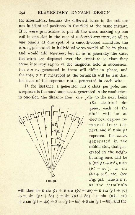
192 ELEMENTARY DYNAMO DESIGN
for alternators, because the different turns in the coil are
not in identical positions in the field at the same instant.
If it were practicable to put all the wires making up one
coil in one slot in the case of a slotted armature, or all in
one bundle at one spot of a smooth-cored armature, the
E.M.F.S generated in individual wires would all be in phaseand would add together, but if, as is generally the case,
the wires are disposed over the armature so that theycome into any region of the magnetic field in succession,
the E.M.F.S generated in them will differ in phase, and
the total E.M.F. measured at the terminals will be less than
the sum of the separate E.M.F. generated in each wire.
If, for instance, a generator has 9 slots per pole, and
E represents the maximum E.M.F. generated in the conductors
in one slot, the distance from one pole to the next being
180 electrical de-
grees, each of the
slots will be 20
electrical degrees re-
moved from the
next, and if E sin p t
represent the E.M.F.
generated in the
middle slot, that gen-
erated in the neigh-
bouring ones will be
E (sin p t + 20), E sin
(pt--
20), E sin
(p t + 40), etc. (see
Fig. 91). The E.M.F.
at the terminals
will then be E sin p t + E sin (p t + 20) + E sin (p t + 40)
+ E sin (p t + 60) + E sin (p t + 80) + E sin (p t - 20)
+ E sin (p t 40) -f E sin (p t 60) + E sin (p t 80), and the
ALTERNATING CURRENTS 193
sum of all these terms is 5786 sin p t, i.e., the maximum
value of the terminal E.M.F. will be 5786 E. If the E.M.F.
had all been in phase the maximum terminal E.M.F. would
have been 9 E since there are 9 slots, and the value of the
E.M.F. for one slot is E, and therefore the result obtained
by multiplying the E.M.F. generated in each conductor bythe total number of conductors will give a result which will
be too large, and must be diminished in the proportion of
9 to 5786. To get the actual E.M.F. generated, the E.M.F.
calculated for the total number of bars in series, as would
be done in c.c. work, must be multiplied by ,which
is = -643.
This factor is called the breadth coefficient, as it dependson the breadth of the winding or on the angular space it
occupies on the circumference of the armature. It is
frequently denoted by the letter q.
The values of q for different cases are given in Parshall
and Hobart's"Generator Design," worked out for different
values of the pole pitch and for different breadths of coil.
For all practical purposes, it may be taken that the
value of q varies from unity for a winding disposed in one
slot per pole to '636 for a distributed winding, i.e., a wind-
ing in which the coils are spread over the whole of the
armature face.
The formula for the E.M.F. (R.M.S. value) of an A.C.
generator thus becomes
E x io 8 = 4-4 q ^ T N
where q is the breadth factor, \, the periodicity, T the
number of turns in series, and N the number of lines per
pole. In three-phase workrwhere the breadth occupied by one
coil can never exceed one-third of the pole pitch, the value
of q can never be very small;
if a value q = -95 be assumed,the formula becomes EXio 8 =4-2^x1*. The formula in
this form has been used throughout Chapters VIII. and IX.
N
CHAPTER VIII
THREE-PHASE GENERATOR
1. General Construction and Specification of an Alter-
nator. An alternating-current generator of the usual
type consists of electromagnets excited by means of con-
tinuous current and of an armature carrying conductors
in which an E.M.F. is induced. Since the current delivered
to the external circuit is to be alternating, there is no need
for a commutator, and the absence of the commutator
allows of two important modifications in the general
construction of the machine as compared with a c.c.
generator.
In the latter the armature is invariably the rotating
part, the magnets are stationary. This arrangement is
necessitated by the fact that the brushes collecting current
from the commutator must have a fixed position with
respect to the magnets ;if the latter revolved while the
armature and commutator were stationary, it would be
necessary that the brush gear should be carried by the
magnets, and should revolve with them. Not only is
this evidently unsatisfactory from a mechanical point of
view, but it would also entail the addition of slip rings,
and a second set of brushes to carry the current from the
rotating brush gear to the stationary external circuit.
This useless complication is always avoided in c.c. machines
by making the armature revolve. In an A.C. generator,
however, the armature may be the stationary part and the
current led directly to the terminals without the need for
any moving contacts;
the continuous current required for
194

THREE-PHASE GENERATOR 195
exciting the magnets is led into two slip rings, to which
the two ends of the magnet winding are connected.
There are certain distinct advantages in this method
of construction : (i) It is easier to secure against the action
of centrifugal force the comparatively small number of
magnet coils than it is to secure in place a large number
of armature coils disposed in many armature slots. (2)
The voltage required from alternators is frequently fairly
high ; 2,000 to 6,000 volts are quite common voltages. The
E.M.F. of the exciting circuit can be kept as low as desired,
and it is certainly preferable that the sliding contacts,
the brushes and slip rings, should be in the low- rather
than in the high-voltage circuit, especially in consideration
of the fact that the exciting current even at a low E.M.F.
does not usually become excessively high. (3) Two slip
rings only are required for the exciting circuit;in the case
of polyphase generators, three or more rings would be
required in the armature circuit if it were the rotating
part. On these accounts the usual practice is to build
alternators with internal revolving magnets, and a stationary
external armature.
The second modification which may be introduced on
account of the absence of a commutator is that the armature
winding need not be symmetrical. Provided the right
number of bars are connected in series, they may be con-
nected in any order whatever. Symmetry is only required
in a continuous-current armature because of the com-
mutation troubles which would be caused by different
coils being unlike in shape or position ;where there is
no commutation to consider the shape of the different coils
is immaterial.
Alternators may be built to give single-phase, two-
phase, three-phase, etc., current.
From the considerations already noted in Chapter VII.,
196 ELEMENTARY DYNAMO DESIGN
three-phase current is that most generally used at present,
and it is therefore proposed in this chapter to work out a
three-phase generator with stationary external armature
and rotating internal field magnets to give 300 kilowatts
at 2,000 volts, and 25 periods per second when running at
375 revolutions per minute on a circuit, the power factor of
which is -8. The usual temperature rise of 70 F. above
surrounding air will be specified, and in addition the specifica-
tion will state the permissible variation of voltage under
different conditions of load.
2. Voltage Regulation. The regulation of an alternator
depends not only on the machine itself, but also on the load
which it is supplying, the regulation becoming much worse
as the power factor of the load becomes smaller. This
point will be further considered later. It will be assumed
that the specification demands that the voltage shall not
rise by more than 5% when the whole load is thrown off,
if the load is non-inductive, and not more than 15% if the
load has a power factor of -8.
In considering the design of an alternator, heating and
efficiency have to be considered in the same way as in a
continuous-current machine, but there is no commutation,
and many of the difficulties which have to be dealt with
in c.c. machines are, therefore, not met with in the design
of an alternator. On the other hand, the question of the
inherent voltage regulation of an alternator is of much
greater importance than in continuous-current machines.
The influence of the armature reaction becomes more
serious when inductive loads are .being supplied, and whilst
these disturbances can be compensated for in c.c. gen-
erators by compound winding which will automatically com-
pensate for changes of load, there is as yet no entirely
satisfactory method of doing this in the case of an alter-
nator. Many devices have been invented for automatic-
THREE-PHASE GENERATOR 197
ally compounding an alternator, but they all involve
considerable complications, and none has come into
general practical use. Almost invariably the regulation
of the E.M.F. is made by hand by introducing resistance
either in the main circuit of .the alternator field magnets
or in the shunt circuit of the exciter. It is therefore of
considerable importance that the inherent regulation of
the generator should be as good as possible. Unfortun-
ately improvement in the regulation is only obtained by
increasing the size of the machine, and the amount of
copper used on its magnets.
The number of poles on the magnets is fixed by the
periodicity and the speed specified. Thus 375 revolutions
per minute ^^ = 6-25 revolutions per second, the
periodicity specified is 25 per second, there must then
2^be
^-^-= 4 periods per revolution, and the number of
periods per revolution is equal to the number of pairs of
poles. The generator contemplated must therefore have
4 pairs of poles, that is 8 poles.
Next consider the current which will be required in each
phase. The total output required is 300 kilowatts, or 100 kilo-
watts per phase. If the windings of the alternator are s-tar
connected, the E.M.F. in each will be -J = 1,150, and the
100,000current required
- =87. This is equivalent to
300 kilowatts so long as the current is in phase with the
E.M.F., but if the load is inductive, say, consisting chiefly
of motors, and is assumed to have a power factor of -8,
then the power given out to the circuit when 87 amperes
per phase are being generated falls to 3 (1,150 x 87 x -8)
= 240,000 watts, and in order to generate the full power
198 ELEMENTARY DYNAMO DESIGN
specified the current must be increased to - 108. Each'o
phase of the generator must therefore be capable of giving
at its terminals an E.M.F. of 1,150 volts, and of carrying
a current of 108 amperes. The volts lost through the
resistance of the winding may be taken at about 2%, say
25 volts, bringing up the total of the E.M.F. to be generatedto 1,175.
It would, of course, be possible to start the design by
using a curve connecting D, the watts per revolution re-
quired from the machine, with d 2l. Such a curve would
differ from that used in Chapter III., as the dimensions of
an alternator are found in practice to be greater for a given
output than is the case for a c.c. generator. This curve
is not, however, as useful a guide for alternating-current
as it is for continuous-current generators, because the
dimensions, the diameter and length of the armature,
depend largely on the regulation required of the machine.
For a more stringent specification as to regulation, a larger
machine is required. For this reason and also as a useful
example of how any design may be started from a
different point of view, it is proposed to consider how
the diameter and length of the armature may be arrived
at tentatively from consideration of the voltage regulation
required.
3. Calculations of Armature Back Ampere-turns.
In considering the effect of load it is necessary to distinguish
between the E.M.F. at the terminals of the machine, and the
E.M.F. actually generated in the winding by its motion in
a magnetic field. The former is called the terminal E.M.F.,
and the latter the impressed E.M.F.
The strength of the magnetic field present will depend
on the number of ampere-turns on each magnet core, less
any .armature ampere-turns which may be opposing the
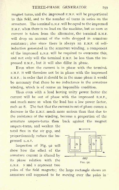
THREE-PHASE GENERATOR 199
magnet turns, and the impressed E.M.F. will be proportional
to this field, and to the number of turns in series on the
armature. The terminal E.M.F. will be equal to the impressed
E.M.F. when there is no load on the machine, but as soon as
current is taken from the alternator, the terminal E.M.F.
will drop on account of the volts dropped in armature
resistance;also since there is always an E.M.F. of self-
induction generated in the armature winding, a componentof the impressed E.M.F. will be required to overcome this,
and not only will the terminal E.M.F. be less than the im-
pressed E.M.F., but it will also differ in phase.
Even when the current is in phase with the terminaV
E.M.F. it will therefore not be in phase with the impressed
E.M.F. ;in order that it should be in the same phase it would
be necessary that there be no inductance in the armature
winding, which is of course an impossible condition.
Thus even with a load having unity power factor the
current will be out of phase with the impressed E.M.F.,
and much more so when the load has a low power factor,
such as -8. The fact that the current is out of phase causes a
decrease in the E.M.F. much more serious than that due to
the resistance of the winding, because a proportion of the
armature ampere-turns then back against the magnet
ampere-turns, and weaken the
total flux in the air gap, and
proportionately reduce the im-
pressed E.M.F.
Inspection of Fig. 92 will
show how the effect of the
armature current is altered byits phase relation with the
E.M.F. N and s represent two
poles of the field magnets ; the large rectangle shows an
armature coil supposed to be moving over the poles in'
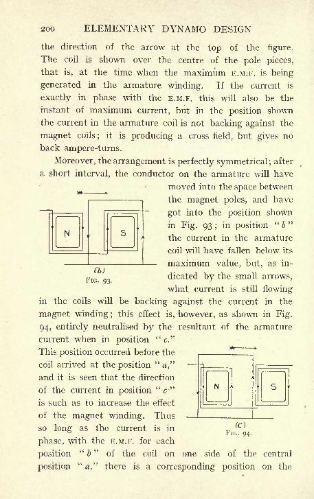
200 ELEMENTARY DYNAMO DESIGN
the direction of the arrow at the top of the figure.
The coil is shown over the centre of the pole pieces,
that is, at the time when the maximum E.M.F. is being
generated in the armature winding. If the current is
exactly in phase with the E.M.F. this will also be the
instant of maximum current, but in the position shown
the current in the armature coil is not backing against the
magnet coils;
it is producing a cross field, but gives no
back ampere-turns.
Moreover, the arrangement is perfectly symmetrical; after
a short interval, the conductor on the armature will have
moved into the space between
the magnet poles, and have
got into the position shown
in Fig. 93 ;in position
"b"
the current in the armature
coil will have fallen below its
- maximum value, but, as in-
dicated by the small arrows,
what current is still flowing
in the coils will be backing against the current in the
magnet winding ;this effect is, however, as shown in Fig.
94, entirely neutralised by the resultant of the armature
current when in position"
c."
This position occurred before the
coil arrived at the position"#,"
and it is seen that the direction
of the current in position "c"is such as to increase the effect
of the magnet winding. Thus
so long as the current is in
phase, with the E.M.F. for each
position"
b"
of the coil on one side of the central
position" a" there is a corresponding position on the
(b)
FIG. 93.
(OFIG. 94.
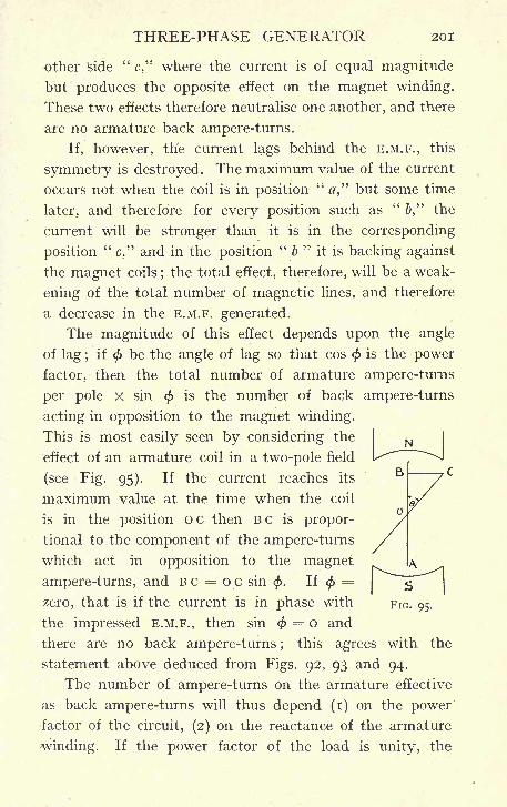
THREE-PHASE GENERATOR 201
other "side"
c," where the current is of equal magnitude
but produces the opposite effect on the magnet winding.
These two effects therefore neutralise one another, and there
are no armature back ampere-turns.
If, however, the current lags behind the E.M.F., this
symmetry is destroyed. The maximum value of the current
occurs not when the coil is in position"a," but some time
later, and therefore for every position such as"
&," the
current will be stronger than it is in the corresponding
position"
c," and in the position"
b"
it is backing against
the magnet coils;the total effect, therefore, will be a weak-
ening of the total number of magnetic lines, and therefore
a decrease in the E.M.F. generated.
The magnitude of this effect depends upon the angle
of lag ;if
<t>be the angle of lag so that cos
<f>is the power
factor, then the total number of armature ampere-turns
per pole x sin < is the number of back ampere-turns
acting in opposition to the magnet winding.
This is most easily seen by considering the
effect of an armature coil in a two-pole field
(see Fig. 95). If the current reaches its
maximum value at the time when the coil
is in the position o c then B c is propor-
tional to the component of the ampere-turns
which act in opposition to the magnet
ampere-turns, and B c = o c sin<f>.
If <=
zero, that is if the current is in phase with
the impressed E.M.F., then sin < = o and
there are no back ampere-turns ;this agrees with
statement above deduced from Figs. 92, 93 and 94.
The number of ampere-turns on the armature effective
as back ampere-turns will thus depend (i) on the powerfactor of the circuit, (2) on the reactance of the armature
-winding. If the power factor of the load is unity, the
the
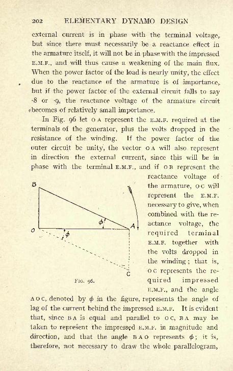
202 ELEMENTARY DYNAMO DESIGN
external current is in phase with the terminal voltage,.
but since there must necessarily be a reactance effect in
the armature itself, it will not be in phase with the impressed
E.M.F., and will thus cause a weakening of the main flux.
When the power factor of the load is nearly unity, the effect
due to the reactance of the armature is of importance,,
but if the power factor of the external circuit falls to say8 or -9, the reactance voltage of the armature circuit
fbecomes of relatively small importance.
In Fig. 96 let o A represent the E.M.F. required at the
terminals of the generator, plus the volts dropped in the
resistance of the winding. If the power factor of the
outer circuit be unity, the vector OA will also represent
in direction the external current, since this will be in
phase with the terminal E.M.F.,and if OB represent the
reactance voltage of
the armature, oc will
represent the E.M.F.
necessary to give, when
combined with the re-
actance voltage, the
required terminal
E.M.F. together with
the volts dropped in
the winding ;that is,
oc represents the re-
quired impressed
E.M.F., and the angle
A o c, denoted by (f>in the figure, represents the angle of
lag of the current behind the impressed E.M.F. It is evident
that, since B A is equal and parallel to o c, B A may be
taken to represent the impressed E.M.F. in magnitude and
direction, and that the angle BAG represents <;
it is,
therefore, not necessary to draw the whole parallelogram,
FIG. 96.
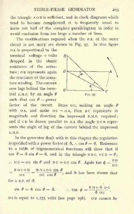
THREE-PHASE GENERATOR 203
the triangle A o B is sufficient, and in clock diagrams which
tend to become complicated, it is frequently usual to
leave out half of the complete parallelogram in order to
avoid confusion from too large a number of lines.
The modifications required when the P.F. of the outer
circuit is not unity are shown in Fig. 97. In this figure
OA is proportional to the
terminal voltage + volts 8
dropped in the ohmic
resistance of the arma-
ture;o B represents again
the reactance of the arma-
ture winding. The current
now lags behind the term-
inal E.M.F. by an angle 6
such that cos 6 = powerfactor of the circuit. Draw oc, making an angle 9
with OA, and make oc = OA, then BC represents in
magnitude and direction the impressed E.M.F. required;
and if c D be drawn parallel to o A the angle D c B repre-
sents the angle of lag of the current behind the impressedE.M.F.
In the generator dealt with in this chapter the regulation
is specified with a power factor of -8, .-. cos = -8. Reference
to a table of trigonometrical functions will show that if
cos 6 = -8 sin =-6, and in the triangle o D c, o c D = ;
"R T^i
.-. o D = o c sin 6 and D c = o c cos 0. Again tan 6 == -DC
FIG. 97.
BO+OD B0-focsin0DC
for a P.F. of -8
o c cos,and it has been shown that
sin = -6 cos 6 = -8. .-. tan (> = o c
8 ococis equal to 1,175 volts (see page 198). OB cannot be
204 ELEMENTARY DYNAMO DESIGN
calculated till the armature winding has been settled, but
previous experience on machines of this size shows it to
be small compared to o c, say about 120 voltsf
., tan * = = -82.8 x 1,175
Reference to a trigonometrical table shows that if tan 9
= -88 sin 6 = -66, the armature back ampere-turns when
the P.F. is -8 will be -66 x the total armature ampere-turns per pole.
In order to ensure that the voltage shall not rise more
than 15%, when full load is thrown off, it is advisable that
the back ampere-turns should not be more than 20% of
the ampere-turns on one magnet pole. It will be possible
in the present instance to put about 11,000 ampere-turnson each magnet core, and the armature back ampere-turns
, , 11,000 X 20may, therefore, be- - = 2,200. Since the back
ampere-turns are -66 of the total armature ampere-turns per
ry
pole, the latter may amount to -h^~ = 3,300.DO
The reason why a difference of as much as 20% in the
number of ampere-turns may be expected to make not
more than 15% difference in the E.M.F. generated is, that if
care be taken to work the iron parts of the magnetic circuit
at fairly high densities, the magnetisation curve of the
machine will be flat, and a given percentage change in the
ampere-turns will make a much smaller proportional change
in the total flux. This will be reverted to later in 9,
when sufficient data haye been obtained to enable the
reactance voltage of the armature to be calculated, and the
magnetisation curve of the machine to be drawn.
4. Armature Dimensions and Number of Bars.
Let it then be determined that the armature of the generator
should not have .more than about 3,300 ampere-turns per
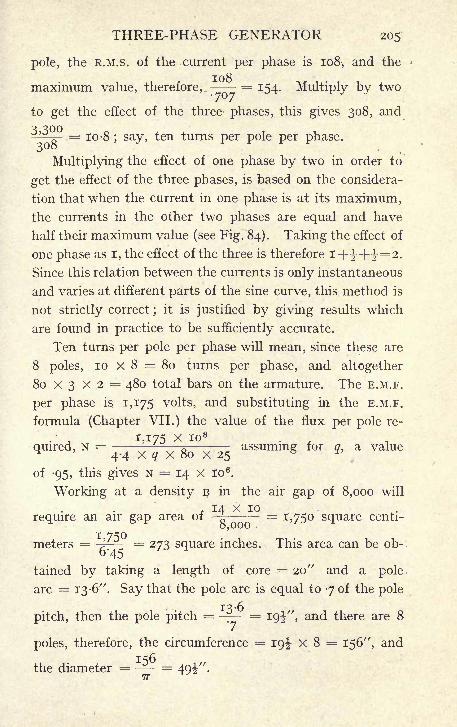
THREE-PHASE GENERATOR 205
pole, the R.M.S. of the current per phase is 108, and the
maximum value, therefore,. = 154. Multiply by two
to get the effect of the three phases, this gives 308, and
3^_ = 10-8 ; say, ten turns per pole per phase.300
Multiplying the effect of one phase by two in order to
get the effect of the three phases, is based on the considera-
tion that when the current in one phase is at its maximum,the currents in the other two phases are equal and have
half their maximum value (see Fig. 84). Taking the effect of
one phase as I, the effect of the three is therefore i+i-+i=2.Since this relation between the currents is only instantaneous
and varies at different parts of the sine curve, this method is
not strictly correct ;it is justified by giving results which
are found in practice to be sufficiently accurate.
Ten turns per pole per phase will mean, since these are
8 poles, 10 x 8 = 80 turns per phase, and altogether
80 x 3 x 2 = 480 total bars on the armature. The E.M.F.
per phase is 1,175 volts, and substituting in the E.M.F.
formula (Chapter VII.) the value of the flux per pole re-
1,175 x io 8
<lmred 'N ==
4.4 x q x 80 x 25assumm for !> a value
of -95, this gives N = 14 x io 6.
Working at a density B in the air gap of 8,000 will
. 14 X 10require an air gap area of
^= 1,750 square centi-
meters = -^= 273 square inches. This area can be ob-
tained by taking a length of core = 20" and a pole
arc = 13 -6". Say that the pole arc is equal to 7 of the pole
pitch, then the pole pitch = -~ = I9i", and there are 8
poles, therefore, the circumference = 19^ X 8 = 156", and
the diameter == -- =7T
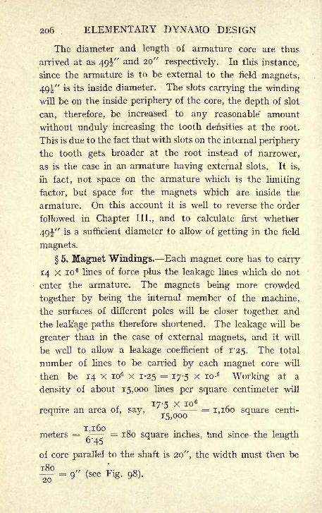
206 ELEMENTARY DYNAMO DESIGN
The diameter and length of armature core are thus
arrived at as 49^" and 20" respectively. In this instance,
since the armature is to be external to the field magnets,
49i" is its inside diameter. The slots carrying the winding
will be on the inside periphery of the core, the depth of slot
can, therefore, be increased to any reasonable" amount
without unduly increasing the tooth densities at the root.
This is due to the fact that with slots on the internal periphery
the tooth gets broader at the root instead of narrower,
as is the case in an armature having external slots. It is,
in fact, not space on the armature which is the limiting
factor, but space for the magnets which are inside the
armature. On this account it is well to reverse the order
followed in Chapter III., and to calculate first whether
49i" is a sufficient diameter to allow of getting in the field
magnets.
5. Magnet Windings. Each magnet core has to carry
14 x io 6 lines of force plus the leakage lines which do not
enter the armature. The magnets being more crowded
together by being the internal member of the machine,
the surfaces of different poles will be closer together and
the leakage paths therefore shortened. The leakage will be
greater than in the case of external magnets, and it will
be well to allow a leakage coefficient of 1-25. The total
number of lines to be carried by each magnet core will
then be 14 X io6 x 1-25 = 17-5 x io-6Working at a
density of about 15,000 lines per square centimeter will
17-5 x io 6
require an area of, say,-~- = 1,160 square centi-
meters = ^= 180 square inches, nd since the length
of core parallel to the shaft is 20", the width must then be
= 9" (see Fig. 98).
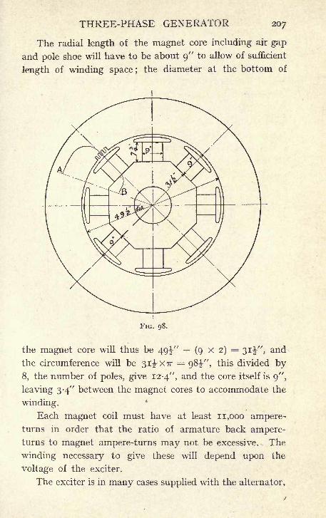
THREE-PHASE GENERATOR 207
The radial length of the magnet core including air gap
and pole shoe will have to be about 9" to allow of sufficient
length of winding space ;the diameter at the bottom of
FIG. 98.
the magnet core will thus be 49-?,-" (9x2)= 3ii", and
the circumference will be 31^X77 = 98^-", this divided by
8, the number of poles, give 12-4", and the core itself is 9",
leaving 3-4" between the magnet cores to accommodate the
winding.
Each magnet coil must have at least 11,000 ampere-turns in order that the ratio of armature back ampere-turns to magnet ampere-turns may not be excessive. The
winding necessary to give these will depend upon the
voltage of the exciter.
The exciter is in many cases supplied with the alternator,
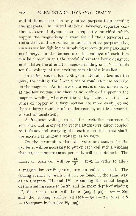
208 ELEMENTARY DYNAMO DESIGN
and it is not used for any other purpose than exciting
the magnets. In central stations, however, separate con-
tinuous current dynamos are frequently provided which
supply the magnetising current for all the alternators in
the station, and are sometimes used for other purposes also,
such as station lighting or supplying motors driving auxiliary
machinery. In the former case the voltage of excitation
can be chosen to suit the special alternator being designed,
in the latter the alternator magnet winding must be suitable
for the voltage of the, exciting sets already installed.
In either case a low voltage is advisable, because the
lower the voltage the fewer turns of conductor are required
on the magnets. An increased current is of course necessary
at the low voltage and there is no saving of copper in the
magnet winding whatever the voltage chosen, but a few
turns of copper of a large section are more easily wound
than a larger number of smaller section, and less space is
wasted in insulation.
A frequent voltage to use for excitation purposes is
100 volts, and many of the recent alternators, direct coupled
to turbines and carrying the exciter on the same shaft,
are excited at as low a voltage as 60 volts.
On the assumption that 100 volts are chosen for the
exciter it will be necessary to put on each coil such a winding
that n,ooo ampere-turns per pole will be obtained. The
TOOE.M.F. on each coil will be - - = 12-5, in order to allow
o
a margin for contingencies, say 10 volts per coil. The
cooling surface for each coil can be found in the same wayas in Chapters III. and IV. Assuming the radial length
of the winding space to be 8", and the mean depth of winding
2", the mean turn will be 2 (20^ + 9^) + 2?r = 66^
and the cooling surface {2 (20 J- + 9^)+27rX2}x8= 580 square inches (see Fig. 99).
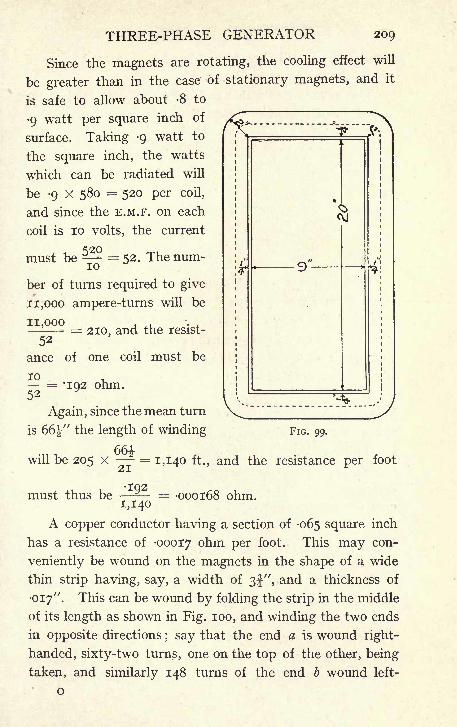
THREE-PHASE GENERATOR 209
Since the magnets are rotating, the cooling effect will
be greater than in the case of stationary magnets, and it
is safe to allow about -8 to
9 watt per square inch of
surface. Taking -9 watt to
the square inch, the watts
which can be radiated will
be -9 X 580 = 520 per coil,
and since the E.M.F. on each
coil is 10 volts, the current
^20must be = 52. The num-
^..,
ber of turns required to give
11,000 ampere-turns will be
11,000 .,
=210, and the resist-
52
ance of one coil must be
FIG. 99.
10 .= *IQ2 ohm.52
Again, since the mean turn
is 66" the length of winding
551.will be 205 x - = 1,140 ft., and the resistance per foot
IQ2must thus be = -000168 ohm.
A copper conductor having a section of -065 square inch
has a resistance of -00017 onm Per foot. This may con-
veniently be wound on the magnets in the shape of a wide
thin strip having, say, a width of 3f", and a thickness of
017". This can be wound by folding the strip in the middle
of its length as shown in Fig. 100, and winding the two ends
in opposite directions; say that the end a is wound right-
handed, sixty-two turns, one on the top of the other, being
taken, and similarly 148 turns of the end b wound left-
o

210 ELEMENTARY DYNAMO DESIGN
handed, a coil will thus be obtained having 210 turns, and
of the shape shown in Fig. 101.
The advantage of this method of winding is that the
two ends of the strip are on the outside of the coil, and
FIG. ioo.,
available for taking off connections without any waste
of space in fetching out a connection from an inside end.
The insulation may consist of strips of cotton cloth say 4"
wide, wound on at the same time as the copper strip so as
to insulate each turn from the next. The whole coil after
winding is saturated in some
good insulating varnish, and
baked at a temperature of
about 180 F., which makes
it quite solid. The two
strips side by side will take
up a radial length of the
core of 2 x 3f = 7J-, allow-
ing J" between the two
turns, and "at each end,
the total radial length of the
winding will be 8". The depth of winding, allowing
01" for the thickness of insulation between the turns
will be 62 X (-017 + -oi)= 1-55" for the bottom half and
148 X (-017 + -oi)= 37" for the top half, the coil will
therefore go into the space available on the magnetcores. Two neighbouring coils are shown in position on
FlG, 101.
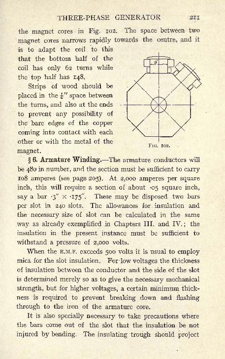
THREE-PHASE GENERATOR 211
FIG. 102.
the magnet cores in Fig. 102. The space between two
magnet cores narrows rapidly towards the centre, and it
is to adapt the coil to this
that the bottom half of the
coil has only 62 turns while
the top half has 148.
Strips of wood should be
placed in the J" space between
the turns, and also at the ends
to prevent any possibility of
the bare edges of the copper
coming into contact with each
other or with the metal of the
magnet.
6. Armature Winding. The armature conductors will
be 480 in number, and the section must be sufficient to carry
108 amperes (see page 205). At 2,000 amperes per square
inch, this will require a section of about -05 square inch,
say a bar -3" x '175". These may be disposed two bars
per slot in 240 slots. The allowances for insulation and
the necessary size of slot can be calculated in the same
way as already exemplified in Chapters III. and IV. ; the
insulation in the present instance must be sufficient to
withstand a pressure of 2,000 volts.
When the E.M.F. exceeds 500 volts it is usual to employmica for the slot insulation. Forlow voltages the thickness
of insulation between the conductor and the side of the slot
is determined merely so as to give the necessary mechanical
strength, but for higher voltages, a certain minimum thick-
ness is required to prevent breaking down and flashing
through to the iron of the armature core.
It is also specially necessary to take precautions where
the bars come out of the slot that the insulation be not
injured by bending. The insulating trough should project
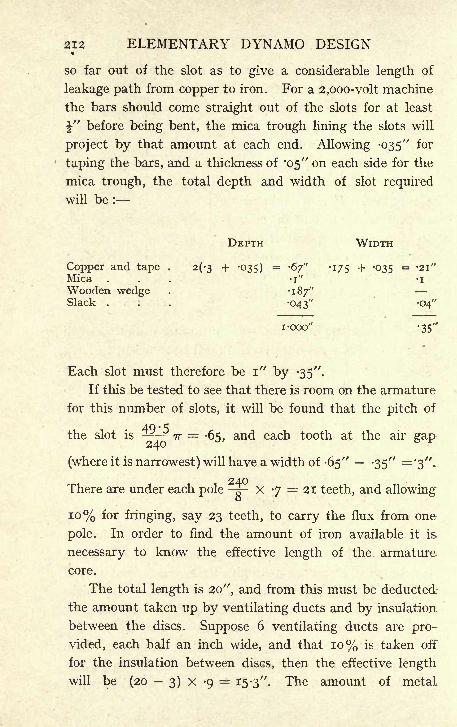
212 ELEMENTARY DYNAMO DESIGN
so far out of the slot as to give a considerable length of
leakage path from copper to iron. For a 2,ooo-volt machine
the bars should come straight out of the slots for at least
\" before being bent, the mica trough lining the slots will
project by that amount at each end. Allowing -035"
for
taping the bars, and a thickness of '05" on each side for the
mica trough, the total depth and width of slot required
will be :
DEPTH WIDTH
Copper and tape . 2(^3 + -035) = -67" -175 + -035 = 2i"Mica , . . -i" -i
Wooden wedge . '187"Slack . . . "043" -04"
i -ooo" -35'"
Each slot must therefore be i" by -35".
If this be tested to see that there is room on the armature
for this number of slots, it will be found that the pitch of
the slot is 5z-J? ^ = .55, and each tooth at the air gap
(where it is narrowest) will have a width of -65" -35" ='3".
There are under each pole -^-X 7 = 21 teeth, and allowing
10% for fringing, say 23 teeth, to carry the flux from one
pole. In order to find the amount of iron available it is-
necessary to know the effective length of the armature
core.
The total length is 20 ", and from this must be deducted
the amount taken up by ventilating ducts and by insulation
between the discs. Suppose 6 ventilating ducts are pro-
vided, each half an inch wide, and that 10% is taken off
for the insulation between discs, then the effective length
will be (20 3) x -9= 15-3". The amount of metal
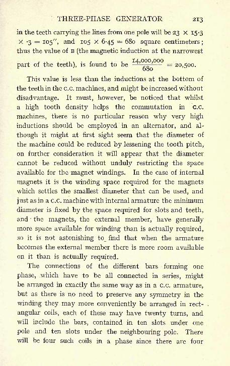
THREE-PHASE GENERATOR 213
in the teeth carrying the lines from one pole will be 23 X 15-3
X -3= 105 ", and 105 x 6-45 = 680 square centimeters
;
thus the value of B (the magnetic induction at the narrowest
part of the teeth), is found to be'-- = 20,500.
This value is less than the inductions at the bottom of
the teeth in the c.c. machines, and might be increased without
disadvantage. It must, however, be noticed that whilst
a high tooth density helps the commutation in c.c.
machines, there is no particular reason why very high
inductions should be employed in an alternator, and al-
though it might at first sight seem that the diameter of
the machine could be reduced by lessening the tooth pitch,
on further consideration it will appear that the diameter
cannot be reduced without unduly restricting the space
available for the magnet windings. In the case of internal
magnets it is the winding space required for the magnetswhich settles the smallest diameter that can be used, and
just as in a c.c. machine with internal armature the minimumdiameter is fixed by the space required for slots and teeth,
and the magnets, the external member, have generally
more space available for winding than is actually required,
so it is not astonishing to_ find that when the armature
becomes the external member there is more room available
on it than is actually required.
The connections of the different bars forming one
phase, which have to be all connected in series, mightbe arranged in exactly the same way as in a c.c. armature,
but as there is no need to preserve any symmetry in the
winding they may more conveniently be arranged in rect-
angular coils, each of these may have twenty turns, and
will include the bars, contained in ten slots under one
pole and ten slots under the neighbouring pole. There
will be four such coils in a phase since there are four
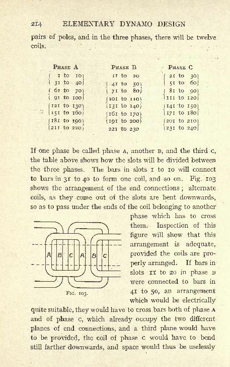
214 ELEMENTARY DYNAMO DESIGN
pairs of poles, and in the three phases, there will be twelve
coils.
If one phase be called phase A, another B, and the third c,
the table above shows how the slots will be divided between
the three phases. The bars in slots I to 10 will connect
to bars in 31 to 40 to form one coil, and so on. Fig. 103
shows the arrangement of the end connections;
alternate
coils, as they come out of the slots are bent downwards,
so as to pass under the ends of the coil belonging to another
phase which has to cross
them. Inspection of this
figure will show that this
arrangement is adequate,
provided the coils are pro-
perly arranged. If bars in
slots II to 20 in phase B
were connected to bars in
FlG> I03< 41 to 50, an arrangement
which would be electrically
quite suitable, they would have to cross bars both of phase A
and of phase c, which already occupy the two different
planes of end connections, and a third plane would have
to be provided, the coil of phase c would have to bend
still farther downwards, and space would thus be uselessly
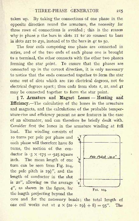
THREE-PHASE GENERATOR 215
taken up. By taking the connections of one phase in the
opposite direction round the armature, the necessity for
three rows of connections is avoided ;this is the reason
why in phase B the bars in slots II to 20 connect to bars
in slots 221 to 230, instead of to the bars in 41 to 50.
The four coils composing one phase are connected in
series, and of the two ends of each phase one is brought
to a terminal, the other connects with the other two phases
forming the star point. To ensure that the phases are
connected up in the correct direction, it is only necessary
to notice that the ends connected together to form the star
come out of slots which are 120 electrical degrees, not 60
electrical degrees apart ;thus ends from slots I, 21, and 41
may be connected together to form the star point.
7. Armature and Magnet Losses Heating and
Efficiency. The calculation of the losses in the armature
and magnets, and the calculations of the probable temper-ature-rise and efficiency present no new features in the case
of an alternator, and can therefore be briefly dealt with.
Consider first the losses in the armature winding at full
load. The winding consists of
10 turns per pole per phase and
each phase will therefore have 80
turns, the section of the con-
ductor is -3 x -175 = -525 square
inch. The mean length of one
turn can be seen from Fig. 104,
the pole pitch is igj-", and the
length of conductor in the slot
is 20", allowing on the average
4", as shown in the figure, for
the length projecting beyond the
core and for the necessary bends; the total length of
one coil works out at 2 X (20 + 19^ -f 8) = 95". The
tote Pttck -'/9-S*
FIG. 104.
216 ELEMENTARY DYNAMO DESIGN
total length of conductor in one phase will therefore
be x 80 = 630 ft., and the resistance of 630 ft. of
copper conductor -0525 square inch in section will be
found from the copper table in the Appendix to be -112
ohm. The watts lost in each phase when 108 amperes
per phase are being taken from the generator will there-
fore be (ro8)2 x -112 = 1,320 watts, and the total copper
loss for the three phases 3,960 watts.
The iron losses in the armature core will be found in
the same way as in Chapter III. Assuming a density
of about 10,000 lines per square centimeter in the armature
14 x io 6
iron, the core must have an area of = 1,40010,000
square centimeters, or -- - 220 square inches, and since'45
the magnetic lines have two paths through the core, each
need be only no square inches in section. But the effec-
tive length of iron parallel to the shaft has been found to
be 15-3 (see page 212). The depth of core must therefore
be =7-25, and the slots are l", the total external
diameter of the armature core will be 49^ + 2 (i -f 7^)
= 66J". From this the weight of core can be found to be
J {(66)
2 -(49i)
2
}x 15-3 x -28 = 6,500 Ib.
The watts lost per Ib. at 25 periods and a magnetic
density of 10,000 lines per square centimeter can be read
off the curve given on page 61, and found to be 2-6. The
total watts lost in the armature iron will be 6,500 X 2-6
= 17,000. The total watts lost on the armature are thus
17,000 + 4,000 = 21,000 and the cylindrical surface of
the armature is 49^ TT x 28, 28" being the length over
the windings (see Fig. 104) 49^ TT x 28 = 4,300, and
THREE-PHASE GENERATOR 217
21,000 , ,
the watts lost per square inch are = 4*8. A loss
4>3
of 5 up to even 6 watts per square inch calculated in
this way is permissible for a rise of 70 F. above the
surrounding air, and the armature should therefore be
perfectly safe as regards heating.
The efficiency of the generator at full load and with
8 P.P. can now be calculated the losses are :
Armature copper losses . . . . . . 4,000
Magnet copper losses . . . . . . 4,000
Armature Iron losses .. ;**,, 17,000
Friction and windage (say) . . . . 3>
28,000
and the output of the machine is 300,000 watts, the total
input must therefore be 328,000, and the efficiency becomes
300,0002 J = .QI or Ql%.328,000
It must be noticed that the efficiency at full load, but
with unity power factor will be somewhat better ;the
armature current will be only 86 amperes instead of 108,
and the armature losses will thus be somewhat smaller
also, as the armature back ampere-turns will be considerably
reduced, fewer ampere-turns will be required on the magnets,
and the losses on the magnet winding will also be reduced.
8. The Magnetic Circuit. The calculations for the
magnetic circuit can be carried out in the same way as in
Chapter III. In the c.c. generator the calculations were
for the purpose of finding the required number of ampere-
turns in order to put the necessary flux in the different
parts of the magnetic current ;in the present instance this
has already been settled at 11,000 ampere-turns per pole
in order to give the required regulation. The iron parts of
the circuit have all been settled, but nothing as yet has
been said as to the radial depth of the air gap ;this dimension
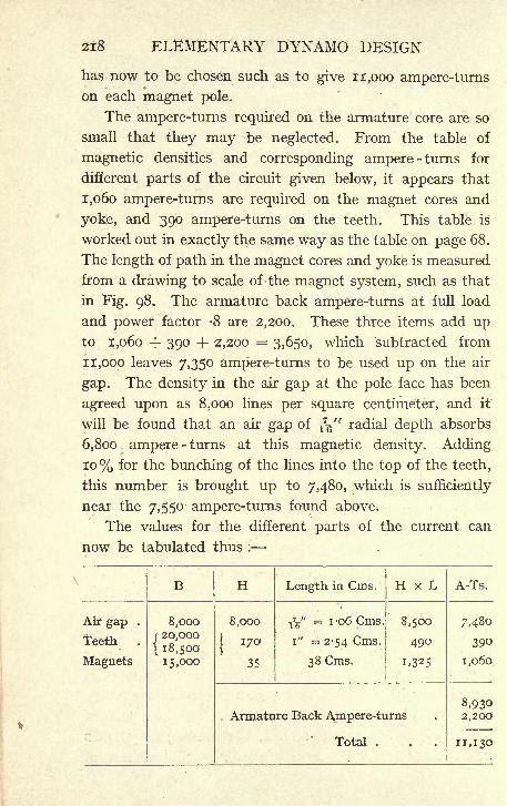
218 ELEMENTARY DYNAMO DESIGN
has now to be chosen such as to give 11,000 ampere-turnson each magnet pole.
The ampere-turns required on the armature core are so
small that they may be neglected. From the table of
magnetic densities and corresponding ampere -turns for
different parts of the circuit given below, it appears that
1,060 ampere-turns are required on the magnet cores and
yoke, and 390 ampere-turns on the teeth. This table is
worked out in exactly the same way as the table on page 68.
The length of path in the magnet cores and yoke is measured
from a drawing to scale of the magnet system, such as that
in Fig. 98. The armature back ampere-turns at full load
and power factor -8 are 2,200. These three items add upto 1,060 -j~ 390 + 2,200 = 3,650, which subtracted from
11,000 leaves 7,350 ampere-turns to be used up on the air
gap. The density in the air gap at the pole face has been
agreed upon as 8,000 lines per square centimeter, and it
will be found that an air gap of T7g" radial depth absorbs
6,800 ampere -turns at this magnetic density. Adding
10% for the bunching of the lines into the top of the teeth,
this number is brought up to 7,480, which is sufficiently
near the 7,550 ampere-turns found above.
The values for the different parts of the current can
now be tabulated thus :
THREE-PHASE GENERATOR 219
This is sufficiently nearly equal to the 11,000 ampere-turns
agreed upon, and it is seen from the table that 8,930 ampere-
turns are required to put the flux through the different parts
of the magnetic circuit, and that the remainder are required
to neutralise the armature back ampere-turns.
9. Magnetisation Curve and Voltage Regulation
Armature Reactance. In order to draw a magnetisation
curve of the machine, which is necessary in Order to find
the variation in E.M.F. when the load is thrown on or off,
repeat the table of ampere-turns on page 218. Increasing
the total flux, and therefore the terminal E.M.F. at no load
in the ratio of say 8 to 9, it will now be found that about
11,270 ampere-turns are required to put the flux through
the magnetic circuit. Again repeat the table, increasirig
the flux in the proportion of 8 to 9-4, and it will be found
that 13,450 ampere-turns are required to put the flux
through. This gives three points through which a curve
can be drawn connecting the ampere-turns on the magnetswith the terminal voltage of the machine at no load.
From the original calculation it is seen that 8,930
ampere-turns give at no load a terminal E.M.F. of 1,175
volts (see page 198) ;from the second and third tables
suggested above 11,270 ampere-turns will give a voltage
of 1,175 Xg= 1,320, and 13,450 ampere -turns will give
a voltage of 1,175 X ^ = 1,380 volts. The curve in
Fig. 105 is drawn through these three points, and represents
the terminal voltage per phase at no load due to any given
number of ampere-turns per pole on the magnets, and it
has been found that at full load, the power factor of the
circuit, being -8, the ampere -turns required are 11,130.
If the load be thrown off the 11,130 ampere-turns will give
1,320 volts (point a on the curve), the rise in volts will
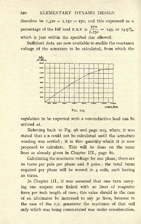
220 ELEMENTARY DYNAMO DESIGN
therefore be 1,320 1,150 = 170, and this expressed as a
percentage of the full load E.M.F. is170 -
-149, or 14-9%,
which is just within the specified rise allowed.
Sufficient data are now available to enable the reactance
voltage of the armature to be calculated, from which the
tooo
1400
1200
ooo
aoo
600
400
^oo
FIG. 105.
regulation to be expected with a non-inductive load can be
arrived at.
Referring back to Fig. 96 and page 203, where it was
stated that o B could not be calculated until the armature
winding was settled;
it is this quantity which it is now
proposed to calculate. This will be done on the same
lines as already given in Chapter III., page 80.
Calculating the reactance voltage for one phase, there are
10 turns per pole per phase and 8 poles ;the total turns
required per phase will be wound in 4 coils, each having
20 turns.
In Chapter III., it was assumed that one turn carry-
ing one ampere was linked with 20 lines of magnetic
force per inch length of core;this value should in the case
of an alternator be increased to say 30 lines, because in
the case of the c.c. generator the reactance of that coil
only which was being commutated was under consideration,
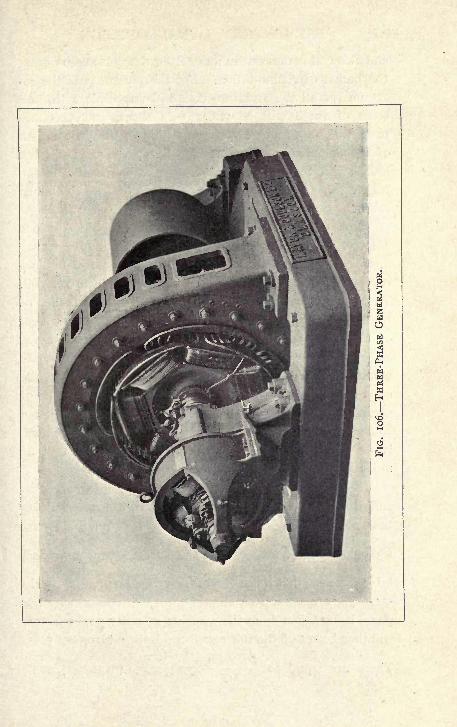
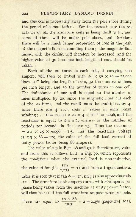
222 ELEMENTARY DYNAMO DESIGN
and this coil is necessarily away from the pole shoes during
the period of commutation. For the present case the re-
actance of all the armature coils is being dealt with, and
some of these will be under pole shoes, and therefore
there will be a much larger proportion of iron in the path
of the magnetic lines surrounding them ; the magnetic flux
linked with the circuit will therefore be increased, and the
higher value of 30 lines per inch length of core should be
taken.
Each of the 20 turns in each coil, if carrying one
ampere, will then be linked with 20 x 30 x 20 = 12,000
lines, 20" being the length of core, 30 the number of lines
per inch length, and 20 the number of turns in one coil.
The inductance of one coil is equal to the number of
lines multiplied by 20, since the magnetic lines cut each
of the 20 turns, and the result must be multiplied by 4,
since there are 4 such coils in series in each phase
winding; .-. L = 12,000 x 20 x 4 X lo~8 =-0096, and the
reactance is equal to 2 TT n L, where n is the number of
periods per second in this case 25. Thus the reactance
= 2 TT X 25 X -0096 = 1-5, and the reactance voltage
is 1-5 X 86 = 129, the value of the full load current at
Unity power factor being 86 amperes.
The value of o B in Figs. 96 and 97 is therefore 129 volts,
and from this it follows that in Fig. 96, which represents
the conditions when the external load is non-inductive,
I2Qthe value of tan < is = -II and from a trigonometrical
table it is seen that if tan < = 'ii, sin $ is also approximately
II. The armature back ampere-turns, with 86 amperes per
phase being taken from the machine at unity power factor,
will thus be -II of the full armature ampere-turns per pole.
These are equal to --- x 2 = 2,450 (pages 204, 205),
THREE-PHASE GENERATOR 223
and the back ampere-turns are therefore 2,450 X -II = 260,
or not much more than one-tenth of the back ampere-turns
when the power factor is -8.
Looking again at the curve, Fig. 105, there will be required
at full load only 9,190 ampere-turns per pole on the magnet,
8,930 to put the magnetic flux through the circuit, and
260 to oppose the armature back ampere-turns, 8,930 + 260
=9,190, and if the load is thrown off, the speed and ex-
citation remaining the same, the terminal E.M.F. will rise
to 1,200 volts per phase ;a rise of 50 volts -^ - =
-043,
r 4*3 %j which again is within the rise of 5% allowed bythe specification.
The very great importance of voltage regulation in the
design of an alternator must be kept in mind, and a careful
comparison of the methods of this chapter with those of
Chapter III. will show that whilst exactly the same general
principles are involved, the relative importance of different
points of the design varies in the two cases, and that it is
in consequence convenient considerably to modify the
point of view from which the design is attacked, and the
order of the various calculations.
Fig. 106 shows the general appearance of an alternator
of the type discussed in this chapter, together with a direct-
coupled exciter.
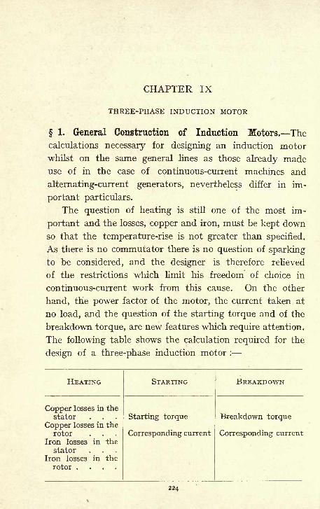
CHAPTER IX
THREE-PHASE INDUCTION MOTOR
1. General Construction of Induction Motors. The
calculations necessary for designing an induction motor
whilst on the same general lines as those already madeuse of in the case of continuous-current machines and
alternating-current generators, nevertheless differ in im-
portant particulars.
The question of heating is still one of the most im-
portant and the losses, copper and iron, must be kept down
so that the temperature-rise is not greater than specified.
As there is no commutator there is no question of sparking
to be considered, and the designer is therefore relieved
of the restrictions which limit his freedom of choice in
continuous-current work from this cause. On the other
hand, the power factor of the motor, the current taken at
no load, and the question of the starting torque and of the
breakdown torque, are new features which require attention.
The following table shows the calculation required for the
design of a three-phase induction motor :
224
THREE-PHASE INDUCTION MOTOR 225
The polyphase induction motor usually consists of a fixed
part known as the stator, made up of annular iron stampings,
which are held together in a cast-iron frame;slots are punched
round the internal periphery, through which are threaded
the copper wires which form the winding. Inside the stator
is placed a rotor which also consists of iron discs threaded
on to a spider, the construction being much the same as
that of a continuous-current dynamo armature. These
discs are also slotted on their external periphery, and the
slots contain the copper windings.
The winding in the stator slots is connected to the
supply mains;the rotor winding, on the other hand, is not
connected to any source of supply, but the currents flowing-
in it are induced by the magnetic flux due to the currents
in the stator winding. In fact, for many purposes, it is
useful to consider the induction motor as a transformer,
the stator winding acting as the primary and inducing an
E.M.F. in the secondary winding, which is carried by the
rotor.
As has been seen in Chapter VII., the effect of polyphase
currents, passed into a suitable winding, such as the
winding of the stator, is to produce a rotating magnetic
field, and the lines of force of this magnetic field, as they
sweep round the rotor, will induce in it currents, the
direction of which will be such as to oppose the motion
of the field. The reaction between the currents and the
field will carry round the rotor with increasing speed in
the same direction as the revolving field. If, however,
the speed of the rotor becomes as great as that of the field,
there will be no cutting of the conductors by the lines of
force, there will be no E.M.F.S generated, and no currents
flowing in the rotor conductors. This speed, which is
called the synchronous speed, can therefore only be attained
under the supposition that there is no load whatever*
p

226 ELEMENTARY DYNAMO DESIGN
on the rotor, and that no force is required to keep it
running at synchronous speed.
This, of course, is unattainable in practice, as there will
always be bearing and air friction to be overcome ; these,
however, will be so small that the rotor attains, when
unloaded, to very nearly synchronous speed. If more load
is put on to the motor, more current must flow in the rotor
circuits, and this can. only be got by the rotor pulling up
slightly, so that the relative velocity of the field and rotor
conductors becomes greater, the E.M.F. being thereby in-
creased and also the rotor current.
The connections of the rotor bars to one another are
evidently of no very great importance ;in fact if a metallic
cylinder be arranged so as to be capable of rotation within
the stator, currents will be generated in this cylinder sufficient
to make it run round and at the same time drive a con-
siderable load. It is found, however, that such a simple
device as this is not very efficient ; of the currents generated
in the metal sheet many are not in the best position to give
a good torque, and the plan is therefore universally adopted
of building up an iron core with slots, and threading in
copper bars. A very usual method is to connect all these
bars together at each end by means of a copper ring which
is riveted, or in some way fastened, to the end of every bar.
The currents find their way along the bars under one pole,
along the end ring and back by bars under a pole of opposite
polarity.
Such a construction is called a squirrel-cage rotor,
it is the simplest possible system of connections and, owing
to the absence of slip rings and moving contacts, is a most
excellent device whenever possible.
Whenever an induction motor can be started on a light
load, a squirrel-cage rotor answers the purpose admirably.
It is, however, found that if it is required to start against a
THREE-PHASE INDUCTION MOTOR 227
torque in any way approaching full load, a squirrel-
cage rotor takes a very excessive starting current. It is
necessary under such conditions to be able to introduce
resistance in the rotor circuit which can be gradually cut
out as the motor accelerates, and for this purpose it is neces-
sary that the rotor should have one or more windings carried
out to slip rings to which the resistance and the necessary
switch are connected. A convenient way of carrying out
this winding, is to wind the rotor with a three-phase star-
connected winding ;three rings are then all that are
necessary to introduce resistance in each branch, and
rotors are usually wound in this way whether they are
intended for use in a three-phase, two-phase, or single-
phase stator.
When a wound rotor is used, it is of course necessary
that the copper should be insulated from the iron of the
core as carefully and thoroughly as in the case of any wind-
ing which is to be connected to an external source of supply.
In the case of the squirrel cage, however, a slight insulation
in the slots suffices, and it is not unusual to connect both
of the copper end rings to the body of the rotor.
It has so far been assumed that the stator carries the
primary winding, that is to say, that the winding on the stator
is connected to the source of supply whilst the rotor carries
the secondary winding, which does not necessarily have anyexternal connections, and has its current induced by the
magnetic flux due to the primary. Theoretically there
is no reason why this arrangement should not be reversed,
and the primary winding put on the rotor, the secondaryon the stator. In practice, however, the first arrangementis in all ordinary cases adopted. The current in the primary
being drawn from an external source of supply, if this
primary is put on the revolving member, there must of
necessity be slip rings to lead it into the winding. If,

228 ELEMENTARY DYNAMO DESIGN
however, the primary is put on the stationary member,
the current can be led straight into its terminals, and if
the conditions allow of the use of a squirrel-cage rotor,
no slip rings at all are required. Moreover, the E.M.F.
on the secondary can always be kept down to whatever
limits may be chosen by a simple arrangement of the
windings. The E.M.F. on the primary, on the other hand,
is fixed by the source of supply. It is obviously better
that the low-voltage current should be the one which has
to pass through movable contacts, and this is another reason
in favour of putting the primary winding on the stator.
2. Calculations of Stator Dimensions for a 100
H.P. Three-Phase Motor. It is proposed to design a three-
phase motor to give 100 H.P. when running at 500 revolu-
tions per minute on a circuit of 500 volts and 25 periods.
It is necessary in the first place to calculate the current
per phase required to give this; roo B.H.P. is equal to an
output of 74,600 watts, and the required input will depend
on the efficiency of the motor and its power factor, and
as these can only be determined after the windings have
been designed, calculations must in the first instance be
based on an assumed efficiency and power factor. For a
motor to give the above output an efficiency of 90% and
a power factor of -92 may be assumed.
The input will then be =83,000 watts, and the
volt-amperes will be -*&. = 90,000 volt-amperes.
The windings of the three phases being symmetrical,
and in every respect alike, the input into each phase will
be one-third of the total, that is, 30,000 volt-amperes must
be put into each of the phases. At this stage it is necessary
to determine whether the motor shall be star-connected
or delta-connected. In the former case the voltage at the

THREE-PHASE INDUCTION MOTOR 229
terminals being 500, the voltage per phase will be- = 290,
and the current per phase will therefore be -- = 103.290
In the case of a delta connection the voltage per phase
is equal to that of the terminal, 500 volts, and the current per
phase will therefore be -- = 60.
If a star connection is decided upon, each winding will
have enough turns to give a back E.M.F. of 290 volts only ;
if a delta connection, the conductors may be of smaller
section as they only have 60 amperes to carry, instead of
103, but more of them will be required, since they have
to give a back E.M.F. of 500 instead of 290 volts.
Whether star or delta winding shall be adopted is a ques-
tion of convenience in winding. In small motors for high-
voltage circuits, where many small conductors are required,
there is an advantage in a star connection, using therefore
conductors of the greatest possible section, and having as
little room as possible lost in insulation. In larger motors
the question must be considered in each case so as to give
the most convenient winding. It is proposed that this
motor shall be star-connected.
The number of poles is fixed by the speed and the
2^ X 60periodicity
- - =3, that is, the number of pairs of
^(_)O
poles must be 3, the number of poles 6. The output co-
efficient (watts per revolution) of the machine is equal to
- = 180. From the curve, Fig. 107, the corresponding
value of d 21 is 8,100 ; this will be satisfied by taking 30"
as the diameter, and 9" as the length of the rotor core.
The curve connecting D and d 21 differs, it will be observed,
from that used for c.c. machines ; the value of d 2l for a given
output is considerably greater in the induction motor.
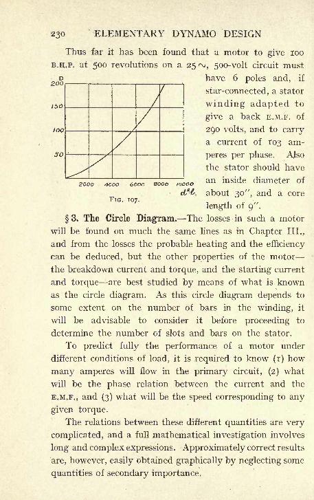
230 ELEMENTARY DYNAMO DESIGN
D200
150
too
200O 4OOO 6OOO 80OO IOOCO
FIG. 107.
Thus far it has been found that a motor to give 100
B.H.P. at 500 revolutions on a 25 ^, 500-volt circuit must
have 6 poles and, if
star-connected, a stator
winding adapted to
give a back E.M.F. of
290 volts, and to carry
a current of 103 am-
peres per phase. AJso
the stator should have
an inside diameter of
about 30 ", and a core
length of 9".
3. The Circle Diagram. The losses in such a motor
will be found on much the same lines as in Chapter III.,
and from the losses the probable heating and the efficiency
can be deduced, but the other properties of the motor
the breakdown current and torque, and the starting current
and torque are best studied by means of what is known
as the circle diagram. As this circle diagram depends to
some extent on the number of bars in the winding, it
will be advisable to consider it before proceeding to
determine the number of slots and bars on the stator.
To predict fully the performance of a motor under
different conditions of load, it is required to know (i) how
many amperes will flow in the primary circuit, (2) what
will be the phase relation between the current and the
E.M.F., and (3) what will be the speed corresponding to any
given torque.
The relations between these different quantities are very
complicated, and a full mathematical investigation involves
long and complex expressions. Approximately correct results
are, however, easily obtained graphically by neglecting some
quantities of secondary importance.
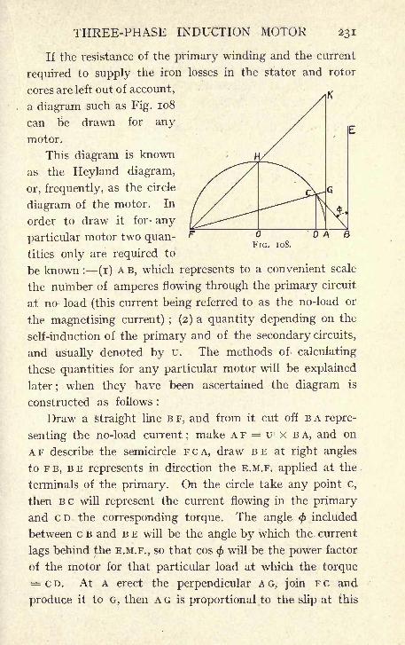
THREE-PHASE INDUCTION MOTOR 231
If the resistance of the primary winding and the current
required to supply the iron losses in the stator and rotor
cores are left out of account,
a diagram such as Fig. 108
can be drawn for any
motor.
This diagram is known
as the Heyland diagram,
or, frequently, as the circle
diagram of the motor. In
order to draw it for- any
particular motor two quan-
tities only are required to
be known : (i) A B, which represents to a convenient scale
the number of amperes flowing through the primary circuit
at no load (this current being referred to as the no-load or
the magnetising current) ; (2) a quantity depending on the
self-induction of the primary and of the secondary circuits,
and usually denoted by u. The methods of calculating
these quantities for any particular motor will be explained
later; when they have been ascertained the diagram is
constructed as follows :
Draw a straight line B F, and from it cut off B A repre-
senting the no-load current ;make A F = u X B A, and on
AF describe the semicircle FCA, draw BE at right angles
to F B, BE represents in direction the E.M.F. applied at the
terminals of the primary. On the circle take any point c,
then BC will represent the current flowing in the primary
and c D the corresponding torque. The angle <j>included
between c B and B E will be the angle by which the current
lags behind the E.M.F., so that cos < will be the power factor
of the motor for that particular load at which the torque
CD. At A erect the perpendicular A G, join FC and
produce it to G, then A G is proportional to the slip at this
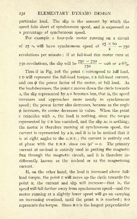
232 ELEMENTARY DYNAMO DESIGN
particular load. The slip is the amount by which the
speed falls short of synchronous speed, and is expressed as
a percentage of synchronous speed.
For example a four-pole motor running on a circuit
, , 25 x 60of 25 ^ will have synchronous speed of - = 750
revolutions per minute;
if at full-load this motor runs at
730 revolutions, the slip will be --^ = -026 or 2-6%.
Thus if in Fig. 108 the point c correspond to full load,
CD will represent the full-load torque, CB full-load current,
and cos</>
the power factor of the motor, at full load. As
the load decreases, the point c moves down the circle towards
A, the slip represented by A G becomes less, that is, the speed
increases and approaches more nearly to synchronous
speed ;the power factor also decreases, because as the angle
$ increases, its cosine decreases in value. When the. point
c coincides with A, the load is nothing, since the torque
represented by c D has vanished, and the slip AG is nothing ;
the motor is therefore running at synchronous speed, the
current is represented by A B, and it is to be noticed that it
is at right angles to the E.M.F. ;the current is entirely out
of phase with the E.M.F. since cos 90 = o. The primary
current at no-load is entirely used in putting the magnetic
flux through the magnetic circuit, and it is therefore in-
differently known as the no-load or as the magnetising
current.
If, on the other hand, the load is increased above full-
load torque, the point c will move up the circle towards the
point H, the current and slip will increase that is, the
speed will fall farther away from synchronous speed and the
motor running at a slightly lower speed will go on carrying
an increasing overload, until the point H; is reached ;H o
represents the torque. Since H o is the longest perpendicular
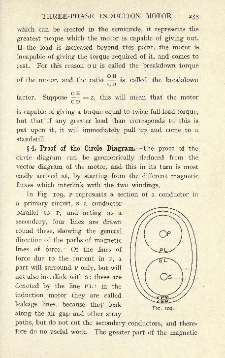
THREE-PHASE INDUCTION MOTOR 233
which can be erected in the semicircle, it represents the
greatest torque which the motor is capable of giving out.
If the load is increased beyond this point, the motor is
incapable of giving the torque required of it, and comes to
rest. For this reason o H is called the breakdown torque
O TT
of the motor, and the ratio - - is called the breakdownC/ J_)
O Hfactor. Suppose
- '- =2, this will mean that the motor
C D
is capable of giving a torque equal to twice full-load torque,
but that if any greater load than corresponds to this is
put upon it, it will immediately pull up and come tp a
standstill.
4. Proof of the Circle Diagram. The proof of the
circle diagram can be geometrically deduced from the
vector diagram of the motor, and this in its turn is most
easily arrived at, by starting from the different magneticfluxes which interlink with the two windings.
In Fig. 109, P represents a section of a conductor in
a primary circuit, s a conductor
parallel to P, and acting as a
secondary, four lines are drawn
round these, showing the general
direction of the paths of magneticlines of force. Of the lines of
force due to the current in P, a
part will surround P only, but will
not also interlink with s; these are
denoted by the line PL: in the
induction motor they are called
leakage lines, because they leak
along the air gap and other stray
paths, but do not cut the secondary conductors, and there-
fore do no useful work. The greater part of the magnetic
FIG. 109.
234 ELEMENTARY DYNAMO DESIGN
field will, however, include both circuits;
this is denoted
by P M. It must be clearly understood that p M represents
the magnetic field due to the current in p only ;it is the
field which would be present if there were no current in s.
Similarly, the field due to the current in the secondary can
be divided into leakage flux, s L, which links with the
secondary only, and main flux s M, which encloses both
secondary and primary.
Again, s M is the field which would be caused by a current
in s on the assumption that no current was flowing in the
primary. When current is flowing -in both circuits, the
field actually present surrounding both conductors is the re-
sultant of P M and s M. The leakage flux for any given motor
may be calculated with more or less accuracy by assuming
leakage paths and comparing the magnetic reluctance
of these combined paths with the reluctance of the main
magnetic circuit;a simple formula for doing this will be
discussed in a future paragraph.
Whatever method is used for estimating the leakage
flux, it is convenient to express it as a fraction of the useful
flux. This method was used in the continuous-current
machines by fixing on a leakage coefficient;in the case of
the induction motor there will be two such coefficients,
one applying to the primary, and one to the secondary.
Every effort is made in induction motor design to keep
down the leakage to as low a value as possible, and whilst
leakage coefficients of the order of 1-2 to 1-3 obtain in c.c.
machines, in the induction motor they are more in the nature
of 1-02.
In drawing the clock diagram for an induction motor,
three magnetic fields have to be considered, (i) the main
flux which cuts both windings ;this is the resultant of p M
and s M (Fig. 109) ; (2) the total flux which cuts the primary ;
this is the resultant of the main flux and the primary leakage
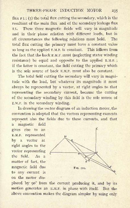
THREE-PHASE INDUCTION MOTOR 235
flux PL; (3) the total flux cutting the secondary, which is the
resultant of the main flux and of the secondary leakage flux
SL. These three magnetic fields will vary in magnitude
and in their phase relation with different loads, but in
all circumstances the following relations must hold. The
total flux cutting the primary must have a constant value
so long as the applied E.M.F. is constant. This follows from
the fact that the back E.M.F. must (neglecting stator winding
resistance) be equal and opposite to the applied E.M.F. ;
if the latter is constant, the field cutting the primary which
is the sole source of back E.M.F. must also be constant.
The total field cutting the secondary will vary in magni-
tude with the load, but whatever its magnitude it must
always be represented by a vector, at right angles to that
representing the secondary current, because the cutting
of the secondary winding by this field is the sole source of
E.M.F. in the secondary winding.
In drawing the vector diagram of an induction motor, the
convention is adopted that the vectors representing currents
represent also the fields due to these currents, and that
a magnetic field
gives rise to an
E.M.F. represented
by a vector at
right angles to the
vector representing
the field. As a
matter of fact, the
magnetic field due
to any current is
on the motor dis-
placed by 90 from the current producing it, and by its
motion generates an E.M.F. in phase with itself. But the
above convention makes the diagram simpler by using only
FIG. no.
236 ELEMENTARY DYNAMO DESIGN
one vector for current and field instead of two, and it is
easy to remember that all the magnetic fields are really dis-
placed on the motor by 90 from the direction of the
vectors representing them.
In Fig. no, the vector diagram of an induction motor
is drawn, the values of u^ and u 2 , the leakage coefficients,
being exaggerated to avoid confusion in the diagram.Draw o A to a convenient scale to represent the magnetic
flux common to both circuits. The current flowing in the
secondary will depend on the load, and can be represented
by o G, the length of o G depending on the load only. Fromo G cut off o F, s o that o G = u 2 o F. Then o F represents
the flux (s M of Fig. 109) due to the secondary, which cuts
both circuits, and o A is the resultant of the fields s M and P M.
Therefore completing the parallelogram ODAF, OD repre-
sents the flux PM of Fig. 109. Produce OD to H, so that
o H = u^o D, then o H represents the resultant of the fluxes
p M and P L, and also the primary current by which these
fields are produced.
Completing the parallelograms o H B F and ODCG, the
resultants o B and o c can be drawn which represent the
total fields cutting the primary and the secondary respec-
tively. That this is so is plain on considering that in Fig.
109 the resultant of p M, p L, and s M is the total field cut-
ting the primary, and that the resultant of s M, s L and P Mis the total field cutting the secondary, whilst in Fig. no,o D represents the field P M, D H the field p L, o F the field s M,
and FG the field SL.
Again, since the E.M.F. generated by any flux is shown
on the diagram by a vector at right angles to the field vector,
it is evident that the applied E.M.F. which is equal and
opposite to the back E.M.F. in the stator, must be represented
by a line at right angles to OB: o E represents the applied
E.M.F. It is necessary that o c be at right angles to OG,
THREE-PHASE INDUCTION MOTOR 237
since o c represents the total field cutting the secondary,
and OG represents the current in the secondary which is
necessarily in phase with the total E.M.F. generated in the
circuit. If in the construction o c does not come at right
angles to o G, it is because the proper phase angle has not been
originally chosen for fixing the position of o G. The length of
o G can be chosen arbitrarily, as it depends only on the load,
but for any length chosen there is a fixed position of o G,
relative to OA, which depends on the values of uland u 2 ,
and which will bring o c at right angles to o G. If this has
not been correctly chosen in the first instance, the diagrammust be modified until o c and o G have their proper relation
at right angles to one another.
Produce o c and H B to meet at K. Produce o B to L,
making L B = u x OB where u = -. Describe a
U1 u2 I
semicircle on LB. Whatever value be chosen for OG,
that is, whatever the load on the motor, the point H will
always be on the semicircle.
c D = u2 X A D because c D o G and AD = o F, and
BH = AD, .-. CD = u2 x BH, again because the triangles
OH.K and ODC are similar;
KH OH OH... ==-,butoH = % xoD, .-.
OD=
1 ,
. . K H = % x c D, and CD = u2 x B H,
.-. K H = % x u2 x B H, and K B = K H BH,
.-. K B = u X U2 X B H B H = (% X U2 l) B H,
KB I.-. B H = - - and - = u ,% U2 I U1 U2 X
.-. BH = u x KB, and by construction LB = u x o B,
.-. the triangles BKO and BHL are similar, and BKO is a
right angle, because it is equal to K o G. It has been seen
that K o and G o are always at right angles, .-. B H L is a right
238 ELEMENTARY DYNAMO DESIGN
angle, and, therefore, H moves on the semicircle drawn on
BL as diameter.fe^pj
Moreover, the field OB is constant whatever the load,
because it supplies the back E.M.F. which is opposite and
equal to the applied E.M.F., OE, which latter is itself
constant. Again o B is the resultant of the primary current
o H and of o F;
if there be no load on the motor o G, and
OF become zero, it is evident that the primary current
o H must then coincide with o B; therefore o B represents
the no-load current of the motor.
If <r =,then cr is called the dispersion coefficient of
the motor, and since in the circle diagram L B = u x o B,
O Rit is evident that LB = -,
a
5. The Magnetising Current. Returning now to
the 100 H.P. motor, specified at the beginning of this chapter,
the relation between the dimensions of the machine, and
the constants required to draw the circle diagram may be
investigated. These constants, as has been seen, are two in
number : the magnetising current to which o B (Fig. 108)
is proportional, and the dispersion coefficient a by which
OB must be divided in order to give BL (Fig. no) the
diameter of the circle.
Both these constants are to a large extent dependent
on the radial depth of the air-gap. Since the greater part
of the reluctance of the magnetic circuit lies in the air-gap,
the magnetising current necessary to produce the main
flux will vary almost directly as the depth of air-gap, and
since a large proportion of the leakage lines have to pass
along the gap, the smaller this is kept the larger will be
the reluctance of the leakage paths, and therefore the smaller
the leakage.
From both points of view, therefore, the air-gap should
THREE-PHASE INDUCTION MOTOR 239
be made as small as possible, and mechanical considerations
alone determine the minimum depth which can be used.
By careful attention to the construction it is quite possible
to work such a machine as this with an air-gap not ex-
ceeding j
1
^" a side. Say i^ millimetre.
Another dimension of great importance is the pole
pitch measured round the inner circumference of the stator.
Since the diameter is 30", and the number of poles 6 this
is equal to ~r^ = 15-5. The pole area available for
carrying the flux will then be 15-5, multiplied by the
effective length of iron in the stator core. The gross
length is 9" (see page 229), and the length of iron
measured parallel to the shaft will be 9" less, say, 2"
(the allowance for 4 ventilating ducts each \" wide),
leaving 7" for discs, and insulation between them, or
7 X -9= 6-3", the effective length of iron. The air-gap
area is therefore 15-5 X 6-3 = 97-5 square inches = 620
square centimeters. As, however, some of the iron will
have to be cut away in order to provide the slots in rotor
and stator, part only of this will be effective. If the
slots both in the stator and rotor are made fully closed
the whole of the area as calculated above is available,
but totally-closed slots increase the leakage by giving an
iron path in addition to the path along the air-gap ; they
therefore increase the value of o-, and this gives an un-
desirably small circle. It is therefore advisable that the
slots should be at any rate partly open.
As a compromise the slot openings may be made of
such width that the effective area of the air-gap is 80%of the total area. If this be done in the present case,
620 x -8 = 490 square centimeters will be obtained as
the area available at each pole for carrying the total flux.
The number of conductors required in the stator winding
240 ELEMENTARY DYNAMO DESIGN
is settled by the consideration that whilst the back E.M.F.
to be generated in each phase is 290, the total flux producing
this back E.M.F. must be kept down to such limits that the
magnetising current required to put it through the various
parts of the magnetic circuit is not too great a proportion
of the full-load current. It is usual to aim at a value of
the magnetising current between 25% and 35% of the full-
load current. In extreme cases values as high as 40% have
been used.
A formula will be given later for calculating directly the
number of turns per pole per phase required in the stator
winding in order to give any desired value of the magnet-
ising current. But in the first place a number of turns,
15 per pole per phase, will be assumed, and the resulting
magnetising current calculated, as this process will most
readily show the steps by which the formula is arrived at.
If there are fifteen turns per pole per phase, and 6 poles
on the machine, the number of turns per phase will be 6 x 15
=90, and the back E.M.F. to be generated in these 90 turns
is 290, the value of N. The total flux per pole is therefore
obtained from the formula
290 X io 8T7TTN = - - = 3-08 x io 6
(see Chapter VII.,
4-2 x 90 x 25
page 193) if a value of -95 be assumed for q, the breadth
coefficient.
But the effective area of the air-gap is 490 square centi-
meters, and the value of B the induction will therefore be
- = 6,250. The ampere - turns required to put
this flux through an air gap of -15 centimeters
io= 6,250 x -15 x - - =750.
4?r
The ampere-turns required for the iron parts of the
circuit are usually so small that it is considered sufficiently
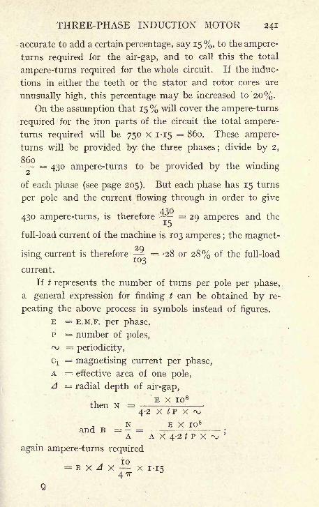
THREE-PHASE INDUCTION MOTOR 241
accurate to add a certain percentage, say 15%, to the ampere-
turns required for the air-gap, and to call this the total
ampere-turns required for the whole circuit. If the induc-
tions in either the teeth or the stator and rotor cores are
unusually high, this percentage may be increased to 20%.
On the assumption that 15% will cover the ampere-turns
required for the iron parts of the circuit the total ampere-
turns required will be 750 X 1-15 = 860. These ampere-
turns will be provided by the three phases ;divide by 2,
- = 430 ampere-turns to be provided by the winding
of each phase (see page 205). But each phase has 15 turns
per pole and the current flowing through in order to give
430 ampere-turns, is therefore - = 29 amperes and the
full-load current of the machine is 103 amperes ;the magnet-
2Qising<
current is therefore = -28 or 28% of the full-load
current.
If t represents the number of turns per pole per phase,
a general expression for finding t can be obtained by re-
peating the above process in symbols instead of figures.
E = E.M.F. per phase,
p = number of poles,
rv =periodicity,
cx= magnetising current per phase,
A = effective area of one pole,
A = radial depth of air-gap,
E x io 8
then N =4-2 X tp x
, N E X IO 8
and B = - = -
A A x 4-2 t P X
again ampere-turns required
A IO= B X A X X I-I54 7T
Q
242 ELEMENTARY DYNAMO DESIGN
E x io 8 x A x io x 1-15~A X 4-2 X t X P X rvj X 4 7T
E X A= -22 X IO 8,A X t X P X
and the ampere-turns per phase are half of this or
E X Aii X io 8
,but again if cx be the magnetising current
A t P (\>
cx x t = ampere turns actually on each phase,
8 E X A... GI X t = -II X IO 8
,
a E X A... t
2 = -ii x io 8
ACjP r\j
This is the general formula enabling the value of t to
give any required magnetising current to be calculated
directly. Applying this to the present case, say that it
is determined that the magnetising current should be 30
amperes, about 30% of the full-load current. Substituting
290 x -15t2 = -II X IO 8 - - = 220,
490 x 30 x 6 x 25
and the square root of 220 being very nearly 15 (15 X 15
= 225), this number would therefore be chosen.
The higher the magnetising current allowed, the fewer
turns need be put on the armature, and therefore the smaller
the machine may be made;on the other hand, a high magnet-
ising current means a bad power factor, especially at low
loads, and therefore a largely increased current for any
given horse power.
6. Copper and Iron Losses and Heating. The
number of turns which it is necessary to put on the stator
having now been ascertained, it will be well, before pro-
ceeding to deal with the other constant required to draw
the circle diagram, to ascertain first whether the required
number of bars can be put on a stator of the given dimensions
without undue heating.
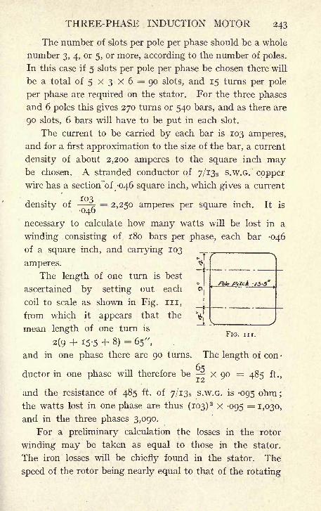
THREE-PHASE INDUCTION MOTOR 243
The number of slots per pole per phase should be a whole
number 3, 4, or 5, or more, according to the number of poles.
In this case if 5 slots per pole per phase be chosen there will
be a total of 5 x 3 X 6 = 90 slots, and 15 turns per pole
per phase are required on the stator. For the three phases
and 6 poles this gives 270 turns or 540 bars, and as there are
90 slots, 6 bars will have to be put in each slot.
The current to be carried by each bar is 103 amperes,
and for a first approximation to the size of the bar, a current
density of about 2,200 amperes to the square inch maybe chosen. A stranded conductor of 7/133 s.w.G. copper
wire has a section "of -046 square inch, which gives a current
density of -?= 2,250 amperes per square inch. It is
040
necessary to calculate how many watts will be lost in a
winding consisting of 180 bars per phase, each bar -046
of a square inch, and carrying 103 ._, ^
amperes. VThe length of one turn is best
ascertained by setting out each
coil to scale as shown in Fig. in,
from which it appears that the
mean length of one turn isFIG. in.
2(9 + 15-5 + 8)= 65",
and in one phase there are 90 turns. The length of con-
ductor in one phase will therefore be x 90 = 485 ft.,
and the resistance of 485 ft. of 7/133 s.w.G. is -095 ohm ;
the watts lost in one phase are thus (103)2 x -095 = 1,030,
and in the three phases 3,090.
For a preliminary calculation the losses in the rotor
winding may be taken as equal to those in the stator.
The iron losses will be chiefly found in the stator. The
speed of the rotor being nearly equal to that of the rotating
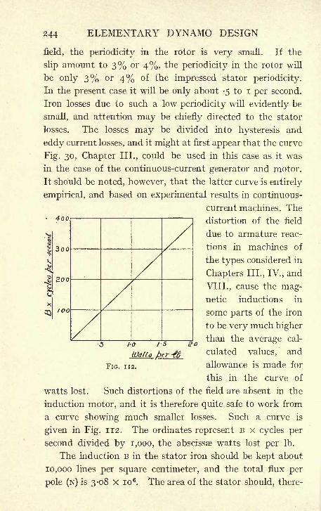
244 ELEMENTARY DYNAMO DESIGN
field, the periodicity in the rotor is very small. If the
slip amount to 3% or 4%, the periodicity in the rotor will
be only 3% or 4% of the impressed stator periodicity.
In the present case it will be only about -5 to I per second.
Iron losses due to such a low periodicity will evidently be
small, and attention may be chiefly directed to the stator
losses. The losses may be divided into hysteresis and
eddy current losses, and it might at first appear that the curve
Fig. 30, Chapter III., could be used in this case as it was
in the case of the continuous-current generator and motor.
It should be noted, however, that the latter curve is entirely
empirical, and based on experimental results in continuous-
current machines. The4oo
3oo
100
distortion of the
due to armature reac-
tions in machines of
the types considered in
Chapters III., IV., and
VIII., cause the mag-netic inductions in
some parts of the iron
to be very much higher
than the average cal-
culated values, and
allowance is made for
this in the curve of
watts lost. Such distortions of the field are absent in the
induction motor, and it is therefore quite safe to work from
a curve showing much smaller losses. Such a curve is
given in Fig. 112. The ordinates represent B x cycles per
second divided by 1,000, the abscissae watts lost per Ib.
The induction B in the stator iron should be kept about
10,000 lines per square centimeter, and the total flux per
pole (N) is 3-08 X io 6. The area of the stator should, there-
i-o is s-o
IQatto /per 46FIG. 112.
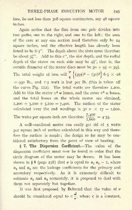
THREE-PHASE INDUCTION MOTOR 245'
fore, be not less than 308 square centimeters, say 48 square
inches.
Again notice that the flux from one pole divides into
two paths, one to the right, and one to the left;the area
of the core at any one section need therefore only be 24
square inches, and the effective length has already been
found to be 6-3". The depth above the slots must therefore
be about 3J". Add to this -i", the slot depth, and the radial
depth of the stator on each side may be 4f-", that is, the
outside diameter of the stator discs must be 30 -f- g|-=
39^-.
The total weight of iron will -j(39i)
2 -(3o)
2
|6-3 x -28
= 930 lb., and 1-3 watt is lost per Ib. (this is taken off
the curve Fig. 112). The total watts are therefore 1,200.
Add to this the stator c 2&> losses, and the rotor c 2
co losses,
and the total losses on the whole motor are obtained,
1,200 + 3,100 + 3,100 = 7,400. The surface of the stator
calculated over the end windings is 30 TT x 17 = 1,600.
The watts per square inch are therefore^
= 4*55.
A well-ventilated motor can easily get rid of 5 watts
per square inch of surface calculated in this way and there-
fore the surface is ample ;the design so far may be con-
sidered satisfactory from the point of view of heating.
7. The Dispersion Coefficient. The value of the
dispersion coefficient must now be found in order that the
circle diagram of the motor may be drawn. It has been
shown in 4 (page 238) that & is equal to ul u 2 i, where
U-L and u2 are the leakage coefficients for the primary and
secondary respectively. As it is extremely difficult to
estimate % and u2 accurately, it is proposed to deal with
them not separately but together.
It was first proposed by Behrend that the value of cr
A -
should be considered equal to c, where c is a constant,
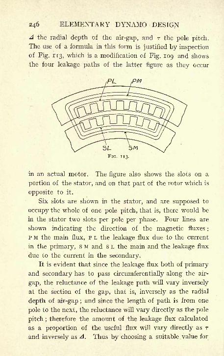
246 ELEMENTARY DYNAMO DESIGN
A the radial depth of the air-gap, and r the pole pitch.
The use of a formula in this form is justified by inspection
of Fig. 113, which is a modification of Fig. 109 and shows
the four leakage paths of the latter figure as they occur
in an actual motor. The figure also shows the slots on a
portion of the stator, and on that part of the rotor which is
opposite to it.
Six slots are shown in the stator, and are supposed to
occupy the whole of one pole pitch, that is, there would be
in the stator two slots per pole per phase. Four lines are
shown indicating the direction of the magnetic fluxes :
p M the main flux, p L the leakage flux due to the current
in the primary, s M and s L the main and the leakage flux
due to the current in the secondary.
It is evident that since the leakage flux both of primary
and secondary has to pass circumferentially along the air-
gap, the reluctance of the leakage path will vary inversely
at the section of the gap, that is, inversely as the radial
depth of air-gap ;and since the length of path is from one
pole to the next, the reluctance will vary directly as the pole
pitch ;therefore the amount of the leakage flux calculated
as a proportion of the useful flux will vary directly as r
and inversely as A. Thus by choosing a suitable value for
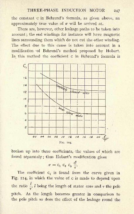
THREE-PHASE INDUCTION MOTOR 247
the constant c in Behrend's formula, as given above, an
approximately true value of cr will be arrived at.
There are, however, other leakage paths to be taken into
account ; the end windings for instance will have magneticlines surrounding them which do not cut the other winding.
The effect due to this cause is taken into account in a
modification of Behrend's method proposed by Hobart.
In this method the coefficient c in Behrend's formula is
c,
0-2 0-4 0-6 08 10 / 14 1-6 18 20
FIG. 114.
broken up into three coefficients, the values of which are
found separately; thus Hobart's modification gives
Aa ==
G! C2C3 -.
The coefficient cx is found from the curve given in
Fig. 114, in which the value of c is made to depend upon
the ratio -, / being the length of stator core and r the pole
pitch. As the length becomes greater in comparison to
the pole pitch so does the effect of the leakage round the
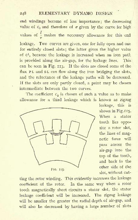
248 ELEMENTARY DYNAMO DESIGN
end windings become of less importance ;the decreasing
value of cx and therefore of o- given by the curve for high
values of - makes the necessary allowance for this end
leakage. Two curves are given, one for fully open and one
for entirely closed slots; the latter gives the higher value
of c 1,because the leakage is increased when an iron path
is provided along the air-gap, for the leakage lines. This
can be seen in Fig. 113. If the slots are closed some of the
flux P L and s L can flow along the iron bridging the slots,
and the reluctance of the leakage paths will be decreased.
If the slots are only partly closed, a point may be chosen
intermediate between the two curves.
The coefficient C2 is chosen of such a value as to make
allowance for a third leakage which is known as zigzag
leakage, this is
shown in Fig. 115.
When a stator
tooth lies oppo-
site a rotor slot,
the lines of mag-netic force will
pass across the
air-gap into the
top of the tooth,
and back to the
other side of the
slot, without cut-
ting the rotor winding. This evidently increases the leakage
coefficient of the rotor. In the same way when a rotor
tooth magnetically short circuits a stator slot, the stator
leakage coefficient will be increased. The zigzag leakage
will be smaller the greater the radial depth of air-gap, and
will also be decreased by having a large number of slots
FJG. 115.
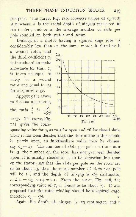
THREE-PHASE INDUCTION MOTOR 249
per pole. The curve, Fig. 116, connects values of C2 with
A M where A is the radial depth of air-gap measured in
centimeters, and M is the average number of slots per
pole counted on both stator and rotor.
Leakage in a motor having a squirrel cage rotor is
considerably less than on the same motor if fitted with
a wound rotor, and
the third coefficient C 3
is introduced to make
allowance for this;C3
is taken as equal to
unity for a wound
rotor and equal to -75
for a squirrel cage.
Applying the above
to the 100 H.P. motor,
the ratio -T
IS
10 15 2-0 2-5 30 35
FIG. 116.A M
15-5
=-57. The curve, Fig.
114, gives the corre-
sponding value for cx as 10-5 for open and 16 for closed slots.
Since it has been decided that the slots of the stator should
be partly open, an intermediate value may be chosen,
say G!= 13. The number of slots per pole on the stator
is 15, the number on the rotor has not yet been decided
upon, it is usually chosen so as to be somewhat less than
on the stator; say that the slots per pole on the rotor are
to be about 13, then the mean number of slots per pole
will be 14, and the depth of air-gap is -15 centimeter,
.-. A M = -15 x 14 = 2-1. From the curve, Fig. 116, the
corresponding value of C2 is found to be about -9. It was
proposed that the rotor winding should be a squirrel cage,
therefore C3= 75. *
Again the depth of air-gap is -15 centimeter, and r
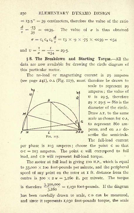
250 ELEMENTARY DYNAMO DESIGN
= 15-5" = 39 centimeters, therefore the value of the ratio
The value of o- is thus obtainedA -15- = = -0039T 39
d c2 c3- == 13 >: -9 x 75 x -0039 = '34
and u = - =or 034
=29-5-
8. The Breakdown and Starting Torque. All the
data are now available for drawing the circle diagram of
this particular motor.
The no-load or magnetising current is 29 amperes
(see page 241), OA (Fig. 117), must therefore be drawn to
scale to represent 29
amperes ;the value of
u is 29-5, therefore
29 x 29-5 = 860 is the
diameter of the circle.
Draw A F, to the same
scale as chosen for o A,
to represent 860 am-
peres, and on A F de-
scribe the semicircle.
The full-load current
per phase is 103 amperes ;choose the point c so that
o c = 103 amperes. The point c will correspond to full
load, and CD will represent full-load. torque.
The motor at full load is giving 100 H.P., which is equal
to 33,000 X 100 foot-pounds per minute, and the peripheral
speed of any point on the rotor at I ft. distance from the
centre is 500 x 2 TT = 3,160 ft. per minute. The torque
is therefore - = 1,030 foot-pounds. If the diagram3,100
has been carefully drawn to scale, CD can be measured,
and since it represents 1,030 foot-pounds torque, the scale
DAO
THREE-PHASE INDUCTION MOTOR 251
to which torque is represented is thus found, and the
torque at any other point can be ascertained.
If, for instance, the diagram has been drawn to the
scale of ]V' = 10 amperes of current, then all measure-
ments being in ^ihs of an inch, OA =2-9, 00 = 10-3,
and CD will be found by measurement to be about 9-5 ;
the maximum torque of the motor is represented by HL,
which is the radius of the circle, and therefore equal to
o/r
half OF .-. HL = =43. Hence the breakdown torque
of the motor is ^ = =4-5 times full-load torque and
the breakdown current. The current corresponding to break-
down is represented by o H ; if this be measured on the
diagram it will be found to be = 63-i6ths of an inch, and
the breakdown current is therefore 630 amperes.
The current which the motor would take if switched on
to the mains when at rest and the corresponding torque
are known as the standstill current and standstill torque.
To find by means of the circle diagram, what the values of
current and torque at standstill will be it is necessary
to know what is the slip at full load. The slip at any load
depends upon the watts lost in the resistance of the rotor
winding.
It is evident that for any given number of bars in the
rotor winding, the E.M.F. generated in the rotor winding
will be proportional to its velocity relative to the field.
Denote this velocity by v, and let the resistance of the rotor
winding be o>, the watts lost in the winding will be pro-
v 2
portional to;now assume the resistance of the rotor
to be increased, and vary the load on the motor in such
a way that in spite of the altered resistance the current
flowing in the rotor remains the same.

252 ELEMENTARY DYNAMO DESIGN
In order to put the same current through an increased
resistance the E.M.F. must be increased, and this can onlybe obtained by a higher relative speed of field and rotor,
the rotor will therefore pull up, and run with an increased
slip. Continue the process until the rotor stands still;
let fl be the resistance of the rotor circuit necessary to
obtain this result, and let v be synchronous speed. At
stand-still, v is the relative speed of field and rotor, and the
v 2
watts lost in rotor winding are now proportional to -^-, andJ2
since the current remains unchanged - = -^ or fi = -a>.
w n v
V 2
Again, ^ represents the total watts supplied to the rotor,
because at standstill the rotor is doing no work, and the whole
of the watts supplied to it must be wasted in its resistance,
v 2
and since by hypothesis the current is not changed, -~'
which represents the total watts supplied to the rotor
at standstill, also represents the watts supplied to the rotor
v 2 v 2
at full load. Therefore at full load -*- -^ representsO) fl
the ratio of the watts lost in the rotor winding to the
total watts supplied to the rotor. Substitute the value of
/2 found above
v
__'
&T~
n ==& v 2
' ~
v
but by definition - is the slip, therefore the slip at full load
is equal to the ratio of watts lost in the winding of the
rotor to the total watts supplied to the rotor.
Evidently in order that the efficiency should be good,
the loss in the rotor winding can only be a small percentage
of the total watts supplied, and therefore the slip at normal
THREE-PHASE INDUCTION MOTOR 253
load is always a small percentage of synchronous speed.
Apart from any question of efficiency, the watts lost in
the rotor must be kept down in value in order to prevent
undue heating.
The rotor watts may be kept at about the same value
as those lost in the stator winding, and these have been
shown on page 243 to be 3,100. Say the watts lost in
rotor resistance are 3,000, loo H.P. = 74,600 watts, and
the watts supplied to the rotor at full load are therefore
Q OOO74,600 + 3,000 = 77,600, and the slip will be =
-039
or 3'9%- AG on the diagram (Fig. 117), therefore, represents a
slip of 3-9%. At standstill the slip is 100%. On A G produced
measure off A K to represent 100 to the same scale that A G
represents 3-9, and join K F;this will cut the circle at a point
M. The point M then represents standstill, o M is the current
which the motor will take, and M N represents standstill
torque. OM does not materially differ from OF, 'and the
standstill current is frequently assumed to be equal to o F.
To find the point M it is not actually necessary to draw
AK, which is generally inconveniently long. Several geo-
metrical devices depending on the properties of similar
triangles are available for finding M without working to
an inconvenient scale.
It is, of course, impossible to allow such a large current
as that represented by OM to flow into the motor even
temporarily, and means are taken, by employing some of
the starting devices described in a later section, to cut
down the starting current.
One way of doing this is to reduce the voltage on the
motor terminals. The effect of decreasing the terminal
E.M.F. is proportionately to reduce the scale of the diagram.
If, for instance, the voltage of supply is reduced to one
half, the current at any point of the circle will also be reduced
254 ELEMENTARY DYNAMO DESIGN
to one half; that is, the diagram remains unaltered, but TV'instead of representing 10 amperes now represents 5 amperes
only. The torque at any point, however, varies not as the
voltage but as the square of the voltage. This is due to
the fact that not only the current decreases proportionately
to the voltage, but the field also decreases in the same
proportion ;the torque being the product of the current,
the magnetic field varies not as the E.M.F. but as the
E.M.F. squared.
The slip is measured to the same scale whatever the
terminal voltage ;it is the ratio of watts lost to total watts
supplied to the rotor, and since these two quantities are
of course altered in the same way by any change of E.M.F.
the ratio between them remains unaltered.
9. Rotor Winding. A very great latitude of choice
is possible in the rotor winding, especially if this is to be
a squirrel cage. The number of bars is immaterial; any
convenient number can be used. The only effect of varying
the number of bars in the rotor winding is to alter the
ratio of transformation between the primary and the
secondary.
In considering the circle diagram it has been assumed
that the ratio of transformation was unity, and that there
was an equal number of bars on the stator and rotor ;
this is necessary in order to avoid great complication in
interpreting the meaning of the different vectors, but in
practice any ratio of transformation may be employed.
If the rotor bars are few in number the E.M.F. generated
will be small, but the current in each bar will have to be
proportionately increased so that the ampere-turns per
pole may have the required value.
In a squirrel-cage winding it is usual to arrange to
have only one bar per slot, as this saves insulation in the
slot and labour in winding.
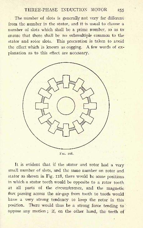
THREE-PHASE INDUCTION MOTOR 255
The number of slots is generally not very far different
from the number in the stator, and it is usual to choose a
number of slots which shall be a prime number, so as to
ensure that there shall be no submultiple common to the
stator and rotor slots. This precaution is taken to avoid
the effect which is known as cogging. A few words of ex-
planation as to this effect are necessary.
FIG. 118.
It is evident that if the stator and rotor had a verysmall number of slots, and the same number on rotor and
stator as shown in Fig. 118, there would be some positions
in which a stator tooth would be opposite to a rotor tooth
at all parts of the circumference, and the magneticflux passing across the air-gap from tooth to tooth would
have a very strong tendency to keep the rotor in this
position. There would thus be a strong force tending to
oppose any motion; if, on the other hand, the teeth of
256 ELEMENTARY DYNAMO DESIGN
one member happened to be opposite the slots of the other,
this effect would not be present and starting would be
much more easily effected. This is, of course, a very extreme
case, but it can easily be seen by drawing one or two ex-
amples, that the same effect is present, though to a smaller
degree, whenever the number of rotor slots and stator
slots have a common submultiple. By making the number
of rotor slots a prime number there can be no factor
common to the number of slots in rotor and stator, and
the cogging is reduced to a minimum.
The necessary size of the rotor bars is most easily arrived
at from the consideration that the total current sheet round
the whole rotor surface does not materially differ in value
from the current sheet on the stator, and that it will there-
fore be necessary to have on the rotor a total section of
copper not differing materially from that on the stator.
As, however, on a squirrel cage the mean turn will be shorter
than that of the stator winding (it usually works out at
something like 80%), the section of rotor copper may be
reduced to 80% of that on the stator, and still allow the
watts lost in both members to remain the same.
On the stator of the 100 H.P. motor under consideration
there are 540 bars, each having a section of -046 square
inch;the total section of copper is therefore 540 x -046 = 25
square inches, and there are on the stator 90 slots. It is pro-
posed to put on the rotor 97 slots, each containing one bar,
the total section of copper on the rotor to be 25 x -8 = 20
20square inches
;the section of each bar will be about = -22
square inch. Say a bar -6 x -35. As the insulation of
the rotor is of comparatively little importance, the allow-
ance in the slot can be kept quite low. A slot" x -45
will be sufficient, the bare copper bar being threaded into
the slot lined with an insulating trough consisting of a
THREE-PHASE INDUCTION MOTOR 257
single thickness of presspahn, or similar material. The
ends of all the bars at each end of the machine are then
joined together by massive copper rings. The section of
these rings must be sufficient to carry the current from half
the bars under one pole ;the other half flows in the opposite
direction.
In the present case there are 97 bars and 6 poles, given
say 16 bars per pole. It would therefore appear at first sight
as if the section of the ring should be equal to that of 8 bars,
but the maximum current will not be flowing at the same
time in all the bars, and since the distribution of current
round the rotor is approximately a sine curve, it will be
sufficient if the section of the rings is 8 X -21 X -636 = 1-07
square inch, -636 being the factor by which the maximumvalue of a sine must be multiplied in order to give the mean
value.
Had it been determined to have a wound rotor instead
of a squirrel cage, it would have been necessary, in order to
keep the three phases symmetrical, that the number of
slots should be divisible by three, the number of phases,
and by six, the number of poles. It must be noted that the
cogging effect is not of so much importance in a wound
rotor since the chief object of winding the rotor is to allow of
the use of starting devices which will give a large starting
torque. It is, however, not advisable that the number of
slots on rotor and stator should be equal ; thus, as there are
on the stator five slots per pole per phase, the number on
the rotor might be chosen to be either 4 or 6, giving 72slots and 108 slots respectively. The number of bars on a
wound rotor may be chosen simply for convenience in
winding, and their section is found as in the case of the
squirrel cage ;the only limitation to the possible choice
in the number of bars is that too high a number will give
a high voltage per phase in the rotor winding at starting,
R
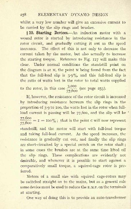
258 ELEMENTARY DYNAMO DESIGN
whilst a very low number will give an excessive current to
be carried by the slip rings and brushes.
10. Starting Devices. An induction motor with a
wound rotor is started by introducing resistance in the
rotor circuit, and gradually cutting it out as the speed
increases. The effect of this is not only to decrease the
current taken by the motor, but also actually to increase
the starting torque. Reference to Fig. 117 will make this
clear. Under normal conditions the standstill point on
the diagram is at M, the point M being found from the fact
that the full-load slip is 3-9%, and this full-load slip is
the ratio Of watts lost in the rotor to total watts supplied
to the rotor, in this case'
^ (see page 253).
If, however, the resistance of the rotor circuit is increased
by introducing resistance between the slip rings in the
proportion of 3-9 to 100, the watts lost in the rotor when full-
load current is passing will be 77,600, and the slip will be
^~r = i = TOO% ;that is the point c will now represent
standstill, and the motor will start with full-load torque
and taking full-load current. As the speed increases, the
resistance is gradually cut out, and finally the slip rings
are short-circuited by a special switch on the rotor shaft;
in some cases the brushes are at the same time lifted off
the slip rings. These complications are evidently not
desirable, and whenever it is possible to start against a
comparatively small torque, a squirrel-cage rotor is pre-
ferred.
Motors of a small size with squirrel cage-rotors maybe switched straight on to the mains, but as a general rule
some device must be used to reduce the E.M.F. on the terminals
at starting.
One way of doing this is to provide an auto-transformer
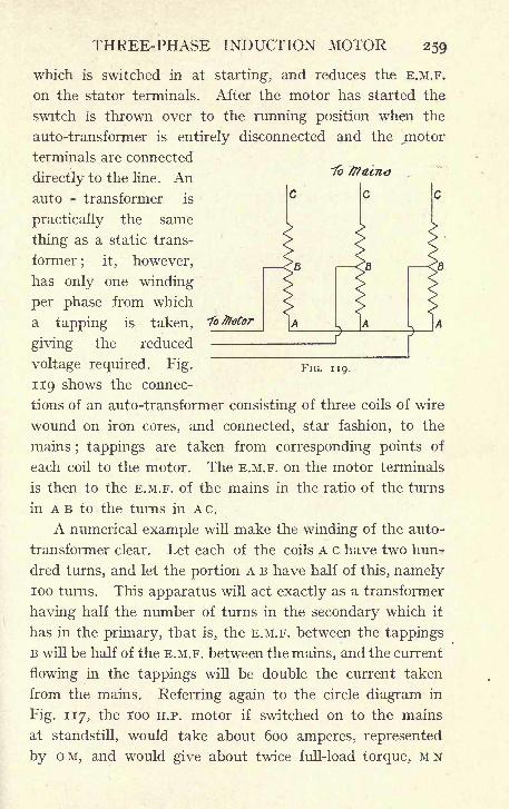
THREE-PHASE INDUCTION MOTOR 259
which is switched in at starting, and reduces the E.M.F.
on the stator terminals. After the motor has started the
switch is thrown over to the running position when the
auto-transformer is entirely disconnected and the jmotor
terminals are connected
directly to the line. Anauto - transformer is
practically the same
thing as a static trans-
former; it, however,
has only one winding
per phase from which
a tapping is taken,
giving the reduced
voltage required. Fig. FIG. n 9 .
119 shows the connec-
tions of an auto-transformer consisting of three coils of wire
wound on iron cores, and connected, star fashion, to the
mains; tappings are taken from corresponding points of
each coil to the motor. The E.M.F. on the motor terminals
is then to the E.M.F. of the mains in the ratio of the turns
in A B to the turns in AC.
A numerical example will make the winding of the auto-
transformer clear. Let each of the coils A c have two hun-
dred turns, and let the portion A B have half of this, namely100 turns. This apparatus will act exactly as a transformer
having half the number of turns in the secondary which it
has in the primary, that is, the E.M.F. between the tappings
B will be half of the E.M.F. between the mains, and the current
flowing in the tappings will be double the current taken
from the mains. Referring again to the circle diagram in
Fig. 117, the 100 H.P. motor if switched on to the mains
at standstill, would take about 600 amperes, represented
by OM, and would give about twice full-load torque, MN
260 ELEMENTARY DYNAMO DESIGN
being about twice c D;the E.M.F. on each phase would be
290 volts.
If, however, the motor be connected to the tappings
at B, (Fig. 119), the voltage on the terminals will be only
= 145, the current in each phase of the motor will be
about 300, and since the current from the mains is only half
of that in the tappings, it will be about 150 amperes, or
one quarter of what would be taken by the motor if con-
nected directly to the mains. On the other hand, the torque
is also reduced to one quarter, for the E.M.F. on the motor
terminals is half, and it has been seen that the torque varies
as the square of the E.M.F. The motor will, therefore, take
about ij times full-load current from the mains, and give
half full-load torque.
Another method of starting a squirrel-cage motor is
to bring out the six ends of the three phases to a suitable
switch, and connect them star forxstarting purposes, and
throw them over to delta connections for running. Since
the back E.M.F. of the star connection is 1-73 times that of
the delta connection this is evidently equivalent, electrically,
to using a transformer with a 1-73 ratio of transformation.
The simplicity of this method is a strong recommendation,
nothing being required except a simple switch to give the
necessary change of connections. The disadvantages are
that the motor must be designed for running on delta
connections when in many cases a star connection would
give a more convenient winding. Also when an auto-
transformer is used several tappings giving different ratios of
transformation can be taken off, and that one chosen for
use which gives the best results. If the star-delta method
of connection is used, the ratio must be 1 to 1-73, and no
other choice can be made.
Many other more or less elaborate methods of starting
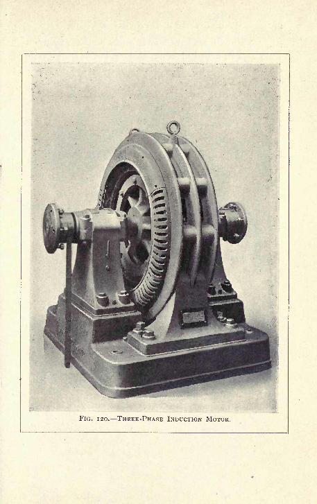
I
FIG. 120. THREE-PHASE INDUCTION MOTOR.
262 ELEMENTARY DYNAMO DESIGN
squirrel-cage motors have been devised, but have been but
little used in actual practice. A very full and interesting
description of these methods will be found in Hobart's"Electric Motors."
A perspective view of a three-phase induction motor is
given in Fig. 120.
CHAPTER X
OTHER VARIETIES OF ALTERNATING-CURRENT
MOTORS
1. Synchronous Motor, Single-Phase Induction Motor,
and Single-Phase Commutator Motor. Whilst the three-
phase induction motor is in most common use at
present, there are several other varieties of alternating-
current motors on the market. The properties of these
differ considerably from those of the induction motor,
and in most cases render them less suitable for general
use. The different classes of alternating-current motors
to be noticed in this chapter are : (i) the synchronous
motor, (2) the single-phase induction motor, and (3) various
classes of motors which are closely related to one another
and known as the single-phase commutator motors.
2. The Synchronous Motor. The synchronous motor
consists merely of an alternating-current generator sup-
plied with current and run as a motor. If supplied with
current, a continuous-current machine will run as a motor,
so the alternating-current machine if supplied with current
will, when once up to synchronous speed, go on running
and give a useful torque. It is, however, to be noticed
that in this case it is necessary that the machine should
be started by some external means, and should be running
at or near synchronous speed before it is switched on to
the mains.
When the machine is standing still, it gives no torque
and has no tendency to run in either direction. The reason
for this can easily be seen by reference to Fig. 121. At
263
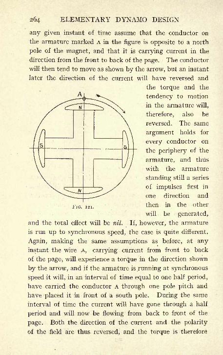
264 ELEMENTARY DYNAMO DESIGN
any given instant of time assume that the conductor on
the armature marked A in the figure is opposite to a north
pole of the magnet, and that it is carrying current in the
direction from the front to back of the page. The conductor
will then tend to move as shown by the arrow, but an instant
later the direction of the current will have reversed and
the torque and the
tendency to motion
in the armature will,
therefore, also be
reversed. The same
argument holds for
every conductor on
the periphery of the
armature, and thus
with the armature
standing still a series
of impulses first in
one direction and
then in the other
will be generated,
and the total effect will be nil. If, however, the armature
is run up to synchronous speed, the case is quite different.
Again, making the same assumptions as before, at anyinstant the wire A, carrying current from front to back
of the page, will experience a torque in the direction shown
by the arrow, and if the armature is running at synchronous
speed it will, in an interval of time equal to one half period,
have carried the conductor A through one pole pitch and
have placed it in front of a south pole. During the same
interval of time the current will have gone through a half
period and will now be flowing from back to front of the
page. Both the direction of the current and the polarity
of the field are thus reversed, and the torque is therefore
FIG. 121.
ALTERNATING-CURRENT MOTORS 265
in the same direction ;the armature will go on running at
synchronous speed with the direction of rotation shown by
the arrow. If the magnets rotate and the armature stands
still the same argument holds, but for the opposite direction
of rotation.
It is evident that a motor giving no torque at standstill,
and requiring' some external agency to get it up to speed,
is not useful for general purposes, and this disability of
the synchronous motor is further increased by the fact
that it requires a supply of continuous current to excite
its magnets.
To these two disadvantages is to be attributed the fact
that synchronous motors have never come into general
use for such work as driving factories and workshops.
There is, however, one class of work where the two
drawbacks noticed above become of minor importance,
and that is when the motors are to be used in sub-stations
where alternating current has to be transformed into con-
tinuous current, usually at a lower pressure.
These stations are almost invariably parts of a large
system of distribution, and the continuous-current bus-bars
are constantly kept alive, that is, there is always a supply
of continuous current available for exciting the synchronous
motor. It is therefore not unusual in such stations to
have some at least of the transformer sets, consisting of a
continuous - current generator, coupled to a synchronous
alternating-current motor. Such a set can always be
started from the continuous-current end by temporarily using
the continuous-current machine as a motor until synchronous
speed is obtained. The synchronous machine is then con-
nected to the alternating-current bars.
The fact that there is constant supply of continuous
current available in these sub-stations is the circumstance
which enables synchronous motors to be used to advantage
266 ELEMENTARY DYNAMO DESIGN
for such work, and as a general statement it may be said
that they are seldom used in any other way. Synchronousmotors may be wound either for single-phase or for poly-
phase systems.
3. The Single-Phase Induction Motor. The single-
phase induction motor resembles in every respect the
polyphase induction motor already described in Chapter
VIII.) except that it is provided with one winding for single-
phase current instead of two or three for multiphase currents.
It is, however, in its properties generally very inferior to
the polyphase machine.
It has been seen that the action of the polyphase
induction motor can be ascribed to a rotating magnetic
field due to the reaction of the different phase windings.
The single-phase motor has no such rotating field, and as
a consequence it gives no torque at starting, and must,
like the synchronous motor, be provided with some
external means for running it up to speed. This is
usually done by providing a secondary winding displaced
by 90 electrical degrees from the main winding ;when it
is desired to start the motor, this winding and the main
winding are both connected to the mains, but there is in-
troduced in the secondary winding either a capacity or a
self-induction of such magnitude as considerably to alter
the phase of the current flowing through the secondary
as compared with that of the current flowing in the main
winding. The result of this is that during the period
of starting the motor acts very much as a two-phase
motor.
If it were possible to introduce a sufficient amount of
capacity or of self-induction to make the current in the one
winding lag 90 behind the other, the motor would be truly
a two-phase motor, but as this is of course impossible,
the two currents do not differ by a quarter phase, and
ALTERNATING-CURRENT MOTORS 267
the starting torque is therefore not good ;a large starting
current is required, and only a small torque is obtained.
These are all considerable drawbacks, but it is, in addi-
tion, found that when the motor has run up to speed, and
the secondary winding is cut out of action, it is even then
seriously inferior, in respect of its power factor and of its
capacity to stand overloads, to the corresponding polyphase
machine. It is also inferior to this in weight efficiency,
that is, the weight for a given rated output is high.
Notwithstanding these disadvantages the single-phase
induction motor was, at any rate until recently, the
only motor available for connection to the supply mains
in those towns where a single-phase alternating-current
system of distribution had been adopted, and in spite of
all its inherent drawbacks, repeated and continuous efforts
have been made to put a suitable single-phase induction
motor on the market. Notwithstanding these efforts this
motor can scarcely be said to have ever been a
commercial success in Great Britain.
4, Single-Phase Commutator Motor. The single-
phase commutator motors have been very largely worked
at during the last few years. There are several kinds
of them all closely related, and their development and
the principles underlying their action may be looked at
from several different points of view. Perhaps one of
the simplest methods is to consider them as derived from
the continuous-current series-wound motor. In such a
motor the direction of rotation depends only on the internal
connections of the machine it depends only on the relative
directions of the currents in the armature and in the
magnet windings, and is independent of the actual direction
of the current. If the direction of the current throughoutthe motor is reversed by altering its connections to the
mains, the direction of rotation remains unaltered for,
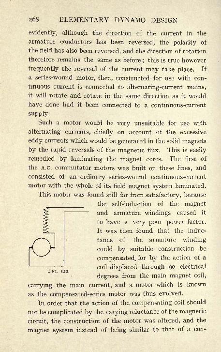
268 ELEMENTARY DYNAMO DESIGN
evidently, although the direction of the current in the
armature conductors has been reversed, the polarity of
the field has also been reversed, and the direction of rotation
therefore remains the same as before;this is true however
frequently the reversal of the current may take place. If
a series-wound motor, then, constructed for use with con-
tinuous current is connected to alternating-current mains,
it will rotate and rotate in the same direction as it would
have done had it been connected to a continuous-current
supply.
Such a motor would be very unsuitable for use with
alternating currents, chiefly on account of the excessive
eddy currents which would be generated in the solid magnets
by the rapid reversals of the magnetic flux. This is easily
remedied by laminating the magnet cores. The first of
the A.c. commutator motors was built on these lines, and
consisted of an ordinary series-wound continuous-current
motor with the whole of its field magnet system laminated.
This motor was found still far from satisfactory, because
the self-induction of the magnetand armature windings caused it
to have a very poor power factor.
It was then found that the induc-
tance of the armature winding
could by suitable construction be
compensated, for by the action of a
coil displaced through 90 electrical*IG. 122.
degrees from the main magnet coil,
carrying the main current, and a motor which is known
as the compensated-series motor was thus evolved.
In order that the action of the compensating coil should
not be complicated by the varying reluctance of the magnetic
circuit, the construction of the motor was altered, and the
magnet system instead of being similar to that of a con-
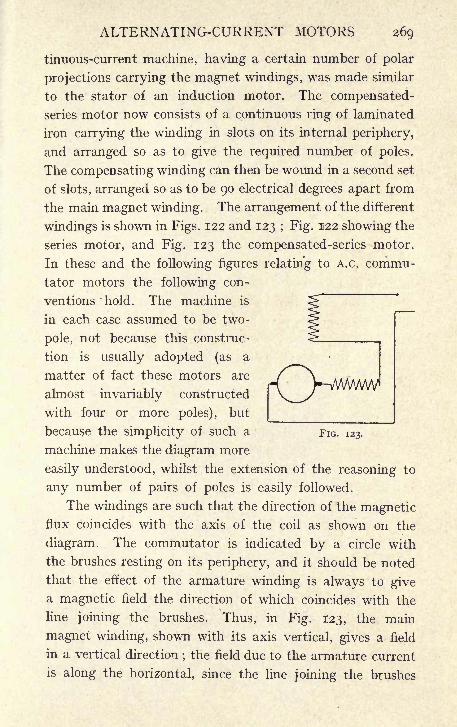
ALTERNATING-CURRENT MOTORS 269
tinuous-current machine, having a certain number of polar
projections carrying the magnet windings, was made similar
to the stator of an induction motor. The compensated-
series motor now consists of a continuous ring of laminated
iron carrying the winding in slots on its internal periphery,
and arranged so as to give the required number of poles.
The compensating winding can then be wound in a second set
of slots, arranged so as to be 90 electrical degrees apart from
the main magnet winding. The arrangement of the different
windings is shown in Figs. 122 and 123 ; Fig. 122 showing the
series motor, and Fig. 123 the compensated-series motor.
In these and the following figures relating to A.c. commu-
tator motors the following con-
ventions hold. The machine is
~~
in each case assumed to be two-
pole, not because this construc-
tion is usually adopted (as a
matter of fact these motors are
almost invariably constructed
with four or more poles), but
pfV-MMA/W
because the simplicity of such a FIG. 123.
machine makes the diagram more
easily understood, whilst the extension of the reasoning to
any number of pairs of poles is easily followed.
The windings are such that the direction of the magneticflux coincides with the axis of the coil as shown on the
diagram. The commutator is indicated by a circle with
the brushes resting on its periphery, and it should be noted
that the effect of the armature winding is always to givea magnetic field the direction of which coincides with the
line joining the brushes. Thus, in Fig. 123, the main
magnet winding, shown with its axis vertical, gives a field
in a vertical direction;the field due to the armature current
is along the horizontal, since the line joining the brushes
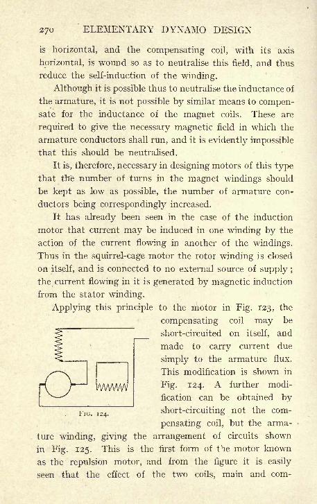
270 ELEMENTARY DYNAMO DESIGN
is horizontal, and the compensating coil, with its axis
horizontal, is wound so as to neutralise this field, and thus
reduce the self-induction of the winding.
Although it is possible thus to neutralise the inductance of
the armature, it is not possible by similar means to compen-sate for the inductance of the magnet coils. These are
required to give the necessary magnetic field in which the
armature conductors shall run, and it is evidently impossible
that this should be neutralised.
It is, therefore, necessary in designing motors of this type
that the number of turns in the magnet windings should
be kept as low as possible, the number of armature con-
ductors being correspondingly increased.
It has already been seen in the case of the induction
motor that current may be induced in one winding by the
action of the current flowing in another of the windings.
Thus in the squirrel-cage motor the rotor winding is closed
on itself, and is connected to no external source of supply ;
the current flowing in it is generated by magnetic induction
from the stator winding.
Applying this principle to the motor in Fig. 123, the'
compensating coil may be
short-circuited on itself, and
made to carry current due
simply to the armature flux.
This modification is shown in
Fig. 124. A further modi-
fication can be obtained by
short-circuiting not the com-
pensating coil, but the arma-
ture winding, giving the arrangement of circuits shown
in Fig. 125. This is the first form of t'ie motor known
as the repulsion motor, and from the figure it is easily
seen that the effect of the two coils, main and com-
/WWWv
FIG. 124.
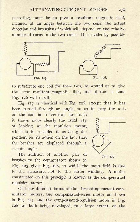
ALTERNATING-CURRENT MOTORS 271
pensating, must be to give a resultant magnetic field,
inclined at an angle between the two coils, the actual
direction and intensity of which will depend on the relative
number of turns in the two coils. It is evidently possible
FIG. 125. FIG. 126.
to substitute one coil for these two, so wound as to give
the same resultant magnetic flux, and if this is done
Fig. 126 will result.
Fig. 127 is identical with Fig. 126, except that it has
been turned through an angle, so as to keep the axis
of the coil in a vertical direction ;
it shows more clearly the usual wayof looking at the repulsion motor,
which is to consider it as being de-
pendent for its action on the fact that
the brushes are displaced through a
certain angle.
The addition of another pair of
brushes to the commutator shown in
Fig. 125 gives Fig. 128, in which the main field is due
to the armature, not to the stator winding. A motor
constructed on this principle is known as the compensated
repulsion motor.
Of these different forms of the alternating-current com-
mutator motors, the compensated-series motor as shown
in Fig. 124, and the compensated-repulsion motor in Fig.
128 are both being developed, to a large extent, on the
FIG. 127.

272 ELEMENTARY DYNAMO DESIGN
Continent and in America for railway traction purposes.
They have the advantage over continuous-current motors
of allowing the use of static transformers for changing the
pressure, so that the supply may be at a considerable pressure,
thus saving copper in the line, and nevertheless be reduced
to the ordinary working pressure at the motor. On the other
hand, the motors being supplied with single-phase current
only, the trolley line, and the
apparatus for collecting current
from it, are much simpler than
would be the case if a three-
phase induction motor were
used. In addition to this these
motors all have characteristics
similar to that of the continuous-FIG. 128.
current series motor, that is, the
speed decreases with the load. A motor behaving in this
way has always been considered specially suitable for
traction purposes, as any great increase in the load reduces
the speed and therefore prevents the motor from being
overloaded to the same extent as would be the case if it
attempted to get over the obstacle with little or no reduc-
tion in speed.
The characteristic of induction motors, on the other hand,
is more similar to that of the shunt-wound continuous-
current motor and they, therefore, do not have the same
advantages when applied to traction purposes. It must,
however, be noted that one great claim in favour of alter-
nating-current systems has hitherto been the absence of the
commutator and of commutator troubles. This class of
motor has a commutator and is as liable as, in fact more
liable than the continuous-current motor to give trouble on
account of sparking at the brushes. It seems, neverthe-
less, to have a great future for long-distance traction, and

ALTERNATING-CURRENT MOTORS 273
in fact appears to some who have spent much time in
developing it to have such good qualities that attempts have
been and are still being made to produce an alternating-
current commutator motor which shall have a characteristic
more nearly resembling the shunt motor, and which will
be easily capable of speed regulation, it being hoped that
such a motor, if successful, might displace the continuous-
current motor in general work, such as driving mills and
workshops. Amongst such motors are the Creedy-Pungaand the Fynn.

APPENDIX
DIMENSIONS, WEIGHTS, AND RESISTANCE OFCOPPER WIRE
ROUND WIRES
STRANDED COPPER CONDUCTORS
274

APPENDIX 275
RECTANGULAR CONDUCTORS
The last line gives the resistance and weight of i ft. of copper
one square inch in section. From this line the resistance and weight
of any section not given in the table can be readily found, remem-
bering that the resistance varies inversely and the weight directly
as the cross section.

276 APPENDIX
One inch
One square inch
One pound
USEFUL CONSTANTS
= 2-54 centimeters.
= 6'45 square centimeters.
= 455 grammes.
One kilogrammeOne centimeter
One square centimeter
= 2-2 Ib.
= -395 inch.
= -155 square inch.
746 watts
33,000 ft. Ibs. per minute
44-2 ft. Ibs. per minute
981 dynes
447,000 dynes
1,000 amperes per square inch
645 amperes per square inch
= One horse-power.= One horse-power.= One watt.
= One gramme.= One pound.= 155 amperes per square centimeter.
= 100 amperes per square centimeter.

INDEX
Addition of* alternating currents,
167
Air-gap induction, 52, 94, 205,218
Alternating current commutatormotors, 267
currents, 161
Alternator, Three-phase, 194
Ampere, Definition of, 9
Ampere-turns, Definition of, 13- and magnetic force, 13
,Number of, 68, 109, 153, 157,218
,Table of, 68, 109, 218
Armature ampere-turns per pole,
70, 82, 204back ampere-turns, 69, 198,20 1, 204
, Closed-coil, 24coils, 28
core, 14,Diameter of, 50, 92, 105
, Length of, 50, 92, 105, Effective length of, 58,
61, 212, 237discs, 14
, Drum, 26
, Elementary, 21
,Number of bars on, 5^
, Open-coil, 24, Ring, 26
slots, 55, 96, Slotted, 29,Smooth core, 29spider, 126
, Stationary, 195
windings, 8, 34Auto-transformer, 259Auxiliary pole, 152Average pitch of winding, 41
Back ampere-turns, 69, 198, 201,204
Back E.M.F., 90, 93
Bars, Number of armature, 52, 94
205Bearings, 124Behrend's formula, 245
Bending of shaft, 122
Bi-polar machines, 31Breadth coefficient, 193Break-down torque, 233, 251" Brush "
arc-lighter, 24Brush holders, 134
rocker, 139Brushes, 22
, Carbon, 134, Copper, 137
Bush, 124
Circuit, Electric, 2
, Magnetic, 2
Clock diagrams, 169-234Closed coil armature, 24Coefficient, Breadth, 193
, Dispersion, 235,
Cogging effect, 255Coils, Armature, 28
Commutating poles, 150Commutation, 76Commutator, 22, 130
coils, Sayer's, 158,Diameter of, 84, 114
, lyength of, 84, 114losses, 85-114motor, Single-phase, 267
, Peripheral speed of, 85, 114Compensated repulsion motor, 271
series motor, 269Compound winding, 45, 46, 75Connections of rotor bars, 226
Core, Effective length of, 58, 61, 212,239
Cotton, Insulating properties of, 18Crane motors, 148Current density in armature bars,
55, 95, 211in carbon brushes, 83
277

278 INDEX
Current, Standstill, 251Currents, Eddy, 14Curve, Magnetisation, 219
, Sine, 161
Delta-connection, 181
Diagram, Circle of induction motor,231
, Heyland's, 231Diameter of armature, 50, 92, 205Dielectric strength, 19Difference of phase, 164Dispersion coefficient, 235Drum armatures, 26
Ducts, Ventilating, 58
Eddy currents, 14Effective length of core, 58, 6 1, 212,
237Efficiency, 86, 116, 217Electrical Units, 3
Electro-magnetic induction, i
Electro-magnets, i
E.M.F., 17, 53in polyphase systems, 183of an alternator, 189
Enclosed type motor, 88
Equalising rings, 43Exciter voltage, 208
Field, Magnetic, 2
, Rotating, 187Flux, Magnetic, per pole, 52, 94, 205,
240Former for magnet winding, 71Full-load torque, 231
Generator, Alternating current, 194, Continuous current, 47
Heyland's diagram, 213Horse-power, 91
Hysteresis, 14 '-.*>'
Impedance, 171
Inductance, 171
Induction, Magnetic, 10
, ,in armature core, 60, 102,
216, 244, ,
in magnets, 66, 104, 206
, ,in teeth, 58, 99
motor, 224Instantaneous value of A.C. current,
162
Insulation, 18
of armature coils, 20, 56resistance, 19
Integration of sine curve, 163Intermittent rating, 148Interpoles, 150Iron losses, 60, 102, 216, 245
Kilowatts, Definition of, 9
Lap winding, 34Leakage, 5 2
coefficient, 157flux, 246
, Zig-zag, 248Length of armature core, 50,
92, 205, 230, Effective, 58, 61,
212, 239Lines of magnetic force, 2
Losses in iron, 60, 102, 216, 245
Magnet former, 71
, Permanent, i
windings, 43Magnetic field, 2
force, 2
, Lines of, 2
,Relation between mag-
netic induction and,17
induction, 10
in armature core, 60,
102, 216, 244in magnets, 66, 104, 206in teeth, 58, 99
pull on armature, 123
reluctance, 3
Magnetisation curve, 219Magnetising current of induction
motor, 231, 238Magnets, Revolving, 195Mean pitch of winding, 41
turn of winding, 59, 71, 101,
113, 208, 243value of alternating current,
163Mica, Insulating properties of, 20
Motor, Induction, 224, 263, Single-phase commutator, 267, Synchronous, 263
Multiphase systems, 180
Multipolar machines, 31
"N," 53, 94, 205, 240

INDEX 279
No-load current of induction motor,
231, 238Number of bars on armature, 52, 94,
205of commutator parts per pole,
54of lines per pole, 52, 94, 205,
240of poles, 47, 82, 93of slots, 55, 97, 211, 243
Ohm, Definition of, 9Ohm's Law, 6
Open-coiled armatures, 24Open-type motor, 88
Paper, Insulating properties of, 20;
Peripheral speed of armature, 64of commutator, 85-114]
Permanent magnet, i
Permeability, n,Relation between magnetic
force and, 12
Phase difference, 164Pitch, Mean, of winding, 41
of winding, 41, Pole, 52, 94, Slot, 57
Pole arc, 52pitch, 52, 94
Poles, Auxiliary, 152, Commutating, 150, Reversing, 152
Polyphase systems, 180Power factor, 176
?, 193Quarter phase, 180
Rating Intermittent, 148Reactance, 80, 171
voltage, 79, 81, 142, 155, 175,220
Regulation of voltage, 197, 220Repulsion motor, 269
, Compensated, 271Resistance, 2
of conductors, 6
, Shunt, 144, Starting, 91, 118
Reversing pole, 152Revolving magnets, 195Ring armature, 26R.M.S. value of alternating current,
164
Rocker, Brush, 139Root mean square value, 164Rotating field, 187Rotor, 225
, Squirrel-cage, 227, Wound, 227
Rotor-bar connections, 226
Sayer's commutator coils, 158Self-induction, 77, 171
Separate excitation, 43Series winding, 44, 45
Series-parallel control, 147Shaft, 121
, Bending of, 122Shunt resistance, 144
winding, 44, 45Silk, Insulating properties'of, 19Sine curves, 161
Size of slots, 56, 98Slip, 232, 251
rings, 22
Slots, Number of, 55, 96, 211
,Size of, 55, 98, 212
Slotted armatures, 29Smooth core armatures, 29Speed control, 143
by shunt resistance, 144by series resistance, 143
, Series-parallel, 147 a
, Synchronous, 225Spider, Armature, 126
Squirrel-cage' rotor, 227Standstill current, 251Star connections, 181Star-delta method of starting in-
duction motor, 260Star point, 186
Starting current, 118, 251resistance, 91, 118
torque, 253Stationary armature, 195Stator, 225Symmetry of winding, 195Synchronous motor, 263
speed, 225
Tables of ampere-turns, 68, 109, Winding, 37, 214
Thomson-Houston arc lighter, 24Three-phase alternator, 194
system, 180
Torque, Breakdown, 233, 251,Full load, 231
, Starting, 253Traction motors, 148Triangle connections, 181

280 INDEX
Turn, Mean, of winding, 59, 71, IOI,
H3, 243Turns per commutator part, 96, 117
Unit of resistance, 9Units, C.G.S. system of, 9
Variable speed motors, 143Vector diagram, 169
of induction motor, 234Ventilating ducts, 58
Voltage of exciter, 207, Regulation, 197, 220
, Resistance, 79, 81, 142, 155,175, 220
Watt, Definition of, 9
Watts lost in iron, 60, 102, 216, 245-. per revolution, 50
- per square inch of coolingsurface, 64, 72, 102,
112, 209, 217, 245Wave winding, 34Winding, Lap, 34
, Magnet, 43of armature, 8
of rotor, 253, Symmetry of, 195
-tables, 37
, Wave, 34
Y-connection, 181
Zig-zag leakage, 248
PRINTED BY CASSHLL & COMPANY, LIMITED, LA BELLE SAUVAGE, LONDON, E.G.


LD21-95m.7,'S7

tV(M\v r*
YC 19845
4822
"