Elektri Ja Magnetismi Ulesandeid - Physoly
48
Translation of Problems in “Elektri Ja Magnetismi ¨ Ulesandeid” Edition 2.0.0 Daniel Yang, Kushal Thaman Edited by: Ashmit Dutta, QiLin Xue Updated April 9, 2020
Transcript of Elektri Ja Magnetismi Ulesandeid - Physoly

Translation of Problems in “Elektri Ja
Magnetismi Ulesandeid”
Edition 2.0.0
Daniel Yang, Kushal Thaman
Edited by: Ashmit Dutta, QiLin Xue
Updated April 9, 2020

Kalda Electricity and Magnetism 1
Preface
Jaan Kalda’s handouts are beloved by physics students both in for a quick challenge, to students preparing for
international Olympiads. The current electricity and magnetism handout (written by Valter Kiisk, ver 2.0) is,
unfortunately for people not fluent in Estonian, fully in Estonian. Here, we have attempted to translate all 175
problems in the handout.
Contact Us
Because none of the authors of this document actually know Estonian, we used a combination of Google
Translate and observing similarities between the handout and other English-language documents. As a result,
some of the translations here are likely wrong or a misinterpretation of the original text. If you do find any
mistakes, or know the source of a specific problem, then please contact us at [email protected]. The most
current and updated version of this document can be found on our website physoly.tech.
Additionally, as we are also high school students and do not have the time to translate 33 pages of hardcore
Estonian physics terminology, this document will only contain the problems provided in the handout, and will
thus require a significant amount of background knowledge to understand and complete. Since the handout
didn’t have answers for all the problems, the answers section is incomplete; however, we will update it as the
problems are solved (and hopefully we can release a solutions document sometime in the future).
Please feel free to contact us at the same email if you are confused on a question. Chances are that many
others will have the same question as you.
1

Kalda Electricity and Magnetism 2
1 DC Circuits
pr 1. For an overcurrent protection, there are two fuses connected in parallel: fuse A has resistance
RA = 1 Ω and maximal current (by which it melts) IAmax = 1 A; fuse B has resistance RB = 2 Ω and
maximal current (by which it melts) IBmax = 1.2 A. What is the maximal total current for such a system
of fuses? What is the total current when the fuse B is substituted with a fuse C which has RC = 2 Ω
and ICmax = 1.7 A? (Kalda Circuits P32)
pr 2. The measuring range of a microammeter is 100 µA. At this current, there is a voltage drop of
0.1 V across the terminals of the ammeter. How should a resistor be connected and how large should
its resistance be to mimic a) a voltmeter with a measuring range of 100 V and b) an ammeter with a
measuring range of 10 A?
pr 3. A light bulb with power 100 W is designed for an input voltage of 110 V. What is the resistance
of the resistor that should be connected in series to the light bulb such that it has the same brightness
with an input voltage of 127 V?
pr 4. Eight identical fluorescent lamps are connected to a constant voltage source as shown in the
figure below. There is a resistor in series with the voltage source with resistance equal to that of a single
lamp. Does the power emitted by the lamps increase or decrease if one of the lamps burn out? If multiple
lamps burn out? Ignore the temperature dependence of the resistance of the lamps. (Similar to Kalda
Circuits P41)
pr 5. A piece of wire with total resistance R0 is shaped into a closed ring, as shown in the figure below.
Two contacts are soldered onto the side of this ring. Determine the resistance between the two contacts
if α = 120.
2

Kalda Electricity and Magnetism 3
pr 6. To determine the resistivity of ocean water, a marine scientist immerses a cable of length 50 mm
in the water. The cable consists of two concentric cylindrical electrodes with inner diameter 40 mm and
outer diameter 45 mm. If the resistance between the electrodes is 9 Ω, determine the resistivity of the
water.
pr 7. A uniform wire of cross-sectional area A0 = 1 mm2 had a millimetre scale marked on it: an
array of streaks with inter-streak distance a0 = 1 mm covered the entire length of the wire. The wire
was stretched in a non-uniform way, so that the inter-streak distance a is now a function of the distance
l from one end of the wire (as measured after the stretching), see figure.The new length of the wire is
L = 4 m. Using the graph, determine the electrical resistance R of the stretched wire assuming that the
resistivity of the wire material is ρ = 1.0 × 10⁻⁶ Ω m. During the stretching, the density of the wire
material remains constant. Note: If a problem contains graphical data, the solution usually comes down
to area of the graph, its slope, or intersections in the graph. (Kalda Circuits P1)
pr 8. The figure below shows part of a larger circuit. Four identical ammeters, each with an internal
resistance of 100 Ω, are connected to the circuit. The readings on the first and second ammeters are
3 mA and 5mA, respectively. Determine the resistance of resistor R.
3

Kalda Electricity and Magnetism 4
pr 9. The circuit in the figure below consists of three identical voltmeters and three identical resistors.
If the reading on the first voltmeter is 19 V and the reading on the third voltmeter is 9 V, find the
reading on the second voltmeter. (Similar to Kalda Circuits P39)
pr 10. Determine the resistance of the circuit shown below using both the potential and current
methods. Note: To simplify the statements, you may consider a current of 1 A passing through the
circuit or that the output terminals are connected to a 1 V voltage source. In the first case, the voltage
drop between the ends of the circuit is numerically equal to the effective resistance, and in the second
case, the current through the circuit is numerically equal to the inverse of the resistance. (Similar to
Kalda Circuits P1)
pr 11. In the figure, R1/R2 = 4. If we add a lamp as shown in the figure below, the current through
R1 will increase by ∆I = 0.1 A. Determine the current through the lamp. (Kalda Circuits P2)
4

Kalda Electricity and Magnetism 5
pr 12. Determine the current through resistor R3 in the circuit shown below.
pr 13. Determine the current through the 8 Ω resistor. (Similar to Kalda Circuits P12)
pr 14. Determine the currents through the batteries. (Kalda Circuits P9)
5

Kalda Electricity and Magnetism 6
pr 15. Determine the resistance of the circuit shown below.
pr 16. To make Christmas decorations, Juku took 10 identical light bulbs (with a rated voltage of 3 V
and a rated power of 0.6 W), and a rectifier with terminal voltage of 5 V. Based on this, he designed
the circuit shown below. He then calculated the necessary value of R such that the voltage across the
bulbs is the same as their rated voltage. However, when the rectifier was switched on, the bulbs were still
dimmer than expected. Further testing showed that the terminal voltage of the rectifier had dropped to
4 V and that the voltage across the bulbs had dropped to 2.4 V. How large should R be to light the
bulbs to their normal brightness?
6

Kalda Electricity and Magnetism 7
pr 17. The maximum current (E/r) is obtained from the voltage source if the resistance of the external
circuit is zero (i.e. the terminals are short-circuited). However, in this case, the electrical power consumed
in the external circuit is also zero. Show that the maximum net power is obtained from a voltage source
if the external circuit resistance is equal to the internal resistance of the source.
pr 18. What is the maximum power that can be drawn from the output terminals of the circuits shown
below Problem 19?
pr 19. Solve the previous problem using equivalent circuits.
pr 20. In the circuit shown below, determine the voltage at the output terminals and the current
through a 10 kΩ resistor if the switch K is a) open; b) closed.
7

Kalda Electricity and Magnetism 8
pr 21. N batteries are connected in parallel. The ith source has emf Ei and internal resistance ri.
What are the effective emf and internal resistance of the combined voltage source?
pr 22. Using the theorem below, resolve Problem 12.
Millman’s theorem states that if we have multiple branches in parallel with one voltage source of emf Ei and one resistor
of resistance Ri on each branch, the total emf is given by U =(∑
iEiRi
)/(∑
i1Ri
)
pr 23. Determine the resistance of the following circuits. (Kalda Circuits P4, P18)
8

Kalda Electricity and Magnetism 9
pr 24. Determine the resistance of the following circuit.
pr 25. Assuming ideal batteries, determine the currents through all resistors in the following circuit.
(Similar to Kalda Circuits P12)
pr 26. Determine the resistance between any 2 terminals in the circuit shown below.
9

Kalda Electricity and Magnetism 10
pr 27. Determine the reading of the ideal ammeter in the circuit below. (Kalda Circuits P36)
pr 28. Determine the readings on the ideal ammeter and ideal voltmeter in the following circuit.
pr 29. Determine the resistance of the following infinite circuit. (Kalda Circuits P16)
10

Kalda Electricity and Magnetism 11
pr 30. Determine the electromotive force and internal resistance of the following system of batteries.
(Kalda Circuits P17)
pr 31. Determine the resistance between two neigbouring nodes in an infinite triangular lattice, as
shown in the figure below. The resistance of the wire connecting any two neighbouring nodes is 1 Ω.
Instructions: Let C be a node that is infinitely far from nodes A and B. Now consider the currents
flowing between these nodes.
pr 32. Determine the resistance between two neighbouring nodes A and B of an infinite cubic lattice
assuming that the edges of the lattice are made of wire, and the resistance of each edge is 1 Ω. (Kalda
Circuits P45)
pr 33. Solve Problem 31 if the wire connecting nodes A and B is cut (i.e. current cannot flow through
that wire).
11

Kalda Electricity and Magnetism 12
pr 34. How man times does the current through the battery change if the polarity of the polarity of
the battery is reversed? All resistors are identical, diodes are ideal, and the internal resistance of the
battery is negligible. (Kalda Circuits P44)
pr 35. Find the power dissipation on each of the diodes in the figure below. These diodes open at
the forward voltage V0 = 1.0 V. It can be assumed that the diode voltage remains equal to V0 for any
forward current, and that for voltages less than V0, there is no current through the diode, as shown in
the figure below. The values of the resistances and of the electromotive force are given in the figure.
(Kalda Circuits P29)
12

Kalda Electricity and Magnetism 13
pr 36. Find the current in the circuit given below; the I(V ) dependence of the diode is shown in graph.
(Kalda Circuits P24)
pr 37. Determine the current flowing through diode D2 in the circuit below. The diodes are identical
and have I(V ) dependence identical to the diode in Problem 36.
pr 38. The figure below shows the I(V ) dependence of the lamp, which is connected to the circuit as
shown in the diagram below. How much power is dissipated by the lamp?
13

Kalda Electricity and Magnetism 14
pr 39. The I − V curve of a thyristor is shown in the graph below. The thyristor is connected in
series with a resistor of resistance R. What minimum voltage U0 must be applied to the circuit for the
thyristor to open (i.e. the current in the circuit increases exponentially)? Sketch the change in current
in the circuit as the voltage applied increases linearly from 0 to U0 and back to 0.
pr 40. In the figure below, the circuit of a simple tunnel-diode-based amplifier is given. Find the
amplification factor for small-amplitude input signals using the following values. (Similar to Kalda
Circuits P25)
pr 41. To determine the current in a circuit, two ammeters with different measuring ranges are con-
nected, one at a time. The ammeter with a measuring range of 10 mA has a current reading of 2.95 mA
and the ammeter with a measuring range of 3 mA has a current reading of 2.90 mA. What is the current
in the circuit without an ammeter present? Assume that we are using a magnetoelectric ammeter with
internal resistance inversely proportional to the measuring range. Note: As the difference between the
ammeter readings is relatively small, a linear approximation may be used and the change in current due
to the additional resistance in the circuit (not due to the ammeter) can be considered to be proportional
to the magnitude of the resistance.
14

Kalda Electricity and Magnetism 15
pr 42. Show that if the resistance of an incandescent lamp is proportional to its (absolute) temperature,
the current-voltage characteristic of the lamp is I ∝ U3/5.
pr 43. The label on a filament lamp reads: 26 V, 0.12 A. At room temperature, the resistance of the
filament was measured to be R0 = 24 Ω. Determine the length, diameter, and operating temperature of
the filament. The filament is made of tungsten and has resistivity ρ0 = 5.3× 10⁻⁸ Ω m.
pr 44. The filament in a halogen light bulb is 5 cm long. The filament is made of tungsten wire with
density 19300 kg/m3 and specific heat capacity 134 J/(kg · K), which can be considered to be constant
over the given temperature range. The resistivity of tungsten as a function of temperature is shown in
the graph below. An excessive DC voltage of 120 V is applied to the bulb. How long does it take to
reach its melting point of 3410C?
15

Kalda Electricity and Magnetism 16
2 DC Circuits With Capacitors
pr 45. In the circuit shown below, all capacitors are initially uncharged. a) Find the current through
the battery immediately after closing switch K. b) What will be the charges on each of the capacitors
after a steady state has been reached?
pr 46. A resistor R and a capacitor C are connected in series with a DC voltage source with emf E .
The capacitor was initially uncharged. Find the power dissipated by the resistor. (Kalda Circuits P57)
pr 47. A capacitor with capacitance C = 10 µF is charged to a potential difference of U0 = 6 V. Then,
a switch completes a circuit containting only the capacitor and a diode with current-voltage characteristic
(let Ud = 1 V) shown in the graph below. How much energy is released at the switch in the form of a
flash (i.e. arcing), if we neglect heat dissipation in the wires?
pr 48. Prove that the formula for the total capacitance of capacitors in series is given by
C =
(1
C1+
1
C2+ · · ·
)−1(Kalda Circuits P60)
16
Kalda Electricity and Magnetism 17
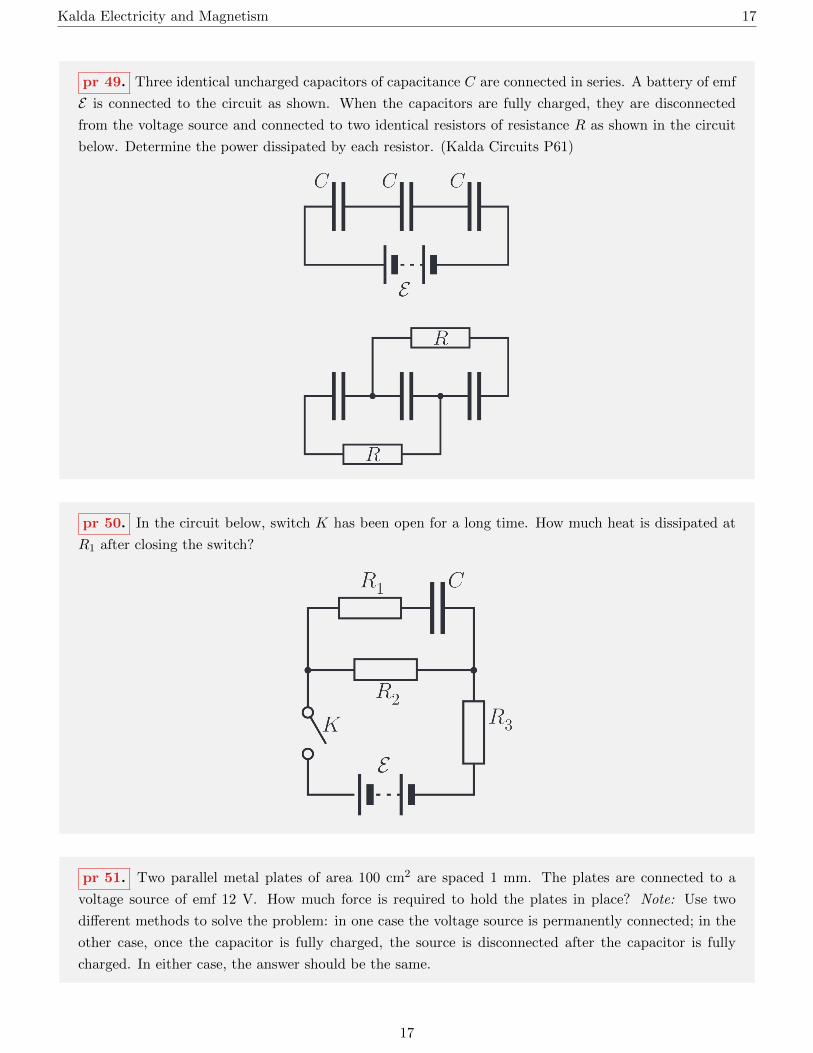
pr 49. Three identical uncharged capacitors of capacitance C are connected in series. A battery of emf
E is connected to the circuit as shown. When the capacitors are fully charged, they are disconnected
from the voltage source and connected to two identical resistors of resistance R as shown in the circuit
below. Determine the power dissipated by each resistor. (Kalda Circuits P61)
pr 50. In the circuit below, switch K has been open for a long time. How much heat is dissipated at
R1 after closing the switch?
pr 51. Two parallel metal plates of area 100 cm2 are spaced 1 mm. The plates are connected to a
voltage source of emf 12 V. How much force is required to hold the plates in place? Note: Use two
different methods to solve the problem: in one case the voltage source is permanently connected; in the
other case, once the capacitor is fully charged, the source is disconnected after the capacitor is fully
charged. In either case, the answer should be the same.
17

Kalda Electricity and Magnetism 18
pr 52. A capacitor consists of two semicircular parallel plates that can rotate frictionlessly around a
common axis (see the figure below). The distance between the plates is d and each plate has radius R
(d R). Determine the torque applied by the lower plate on the upper plate when the angle of overlap
of the two plates is α (α d/R) and a voltage U is applied to the plates.
pr 53. Find the minimum force necessary to remove a dielectric completely filling the space between
two plates of a capacitor if the width of the plate is a, the distance between the plates is d, the dielectric
constant is κ, and a voltage U is applied to the capacitor.
pr 54. A parallel plate capacitor has plates spaced a distance d apart. A voltage U is applied across
the capacitor. The capacitor is placed, along its lower edge, in a liquid with dielectric constant κ and
density ρ. How high does the liquid rise between the plates of the capacitor? Do not consider surface
tension.
pr 55. The space between the plates of a capacitor is filled with an insulator with dielectric constant
5 and resistivity 1012 Ω m. Find the time constant of the capacitor.
pr 56. The figure below shows the schematic for a simple timer. Assume that the inputs of the
comparator consume practically no current. The capacitor is initially uncharged. How long does it take
for the alarm to go off after closing the switch? Note: The triangular circuit element is a comparator - a
device that emits a signal (which in turn triggers an alarm) as soon as the potential difference between
its inputs becomes positive. Dashed lines indicate connections between the comparator and alarm, but
this is not required to solve the problem.
18

Kalda Electricity and Magnetism 19
pr 57. Find the time constant of the capacitor in the diagram below after closing switch K.
pr 58. An AC voltage as shown below is applied to a circuit consisting of a resistor and a capacitor
connected in series. Determine the power dissipated by the resistor in the following cases: a) T RC;
b) T RC.
pr 59. A time-dependent current flows through a circuit consisting of a resistor and a capacitor con-
nected in series. Determine the amplitude of voltage fluctuations in the capacitor in the following cases:
a) T RC; b) T RC.
19
Kalda Electricity and Magnetism 20
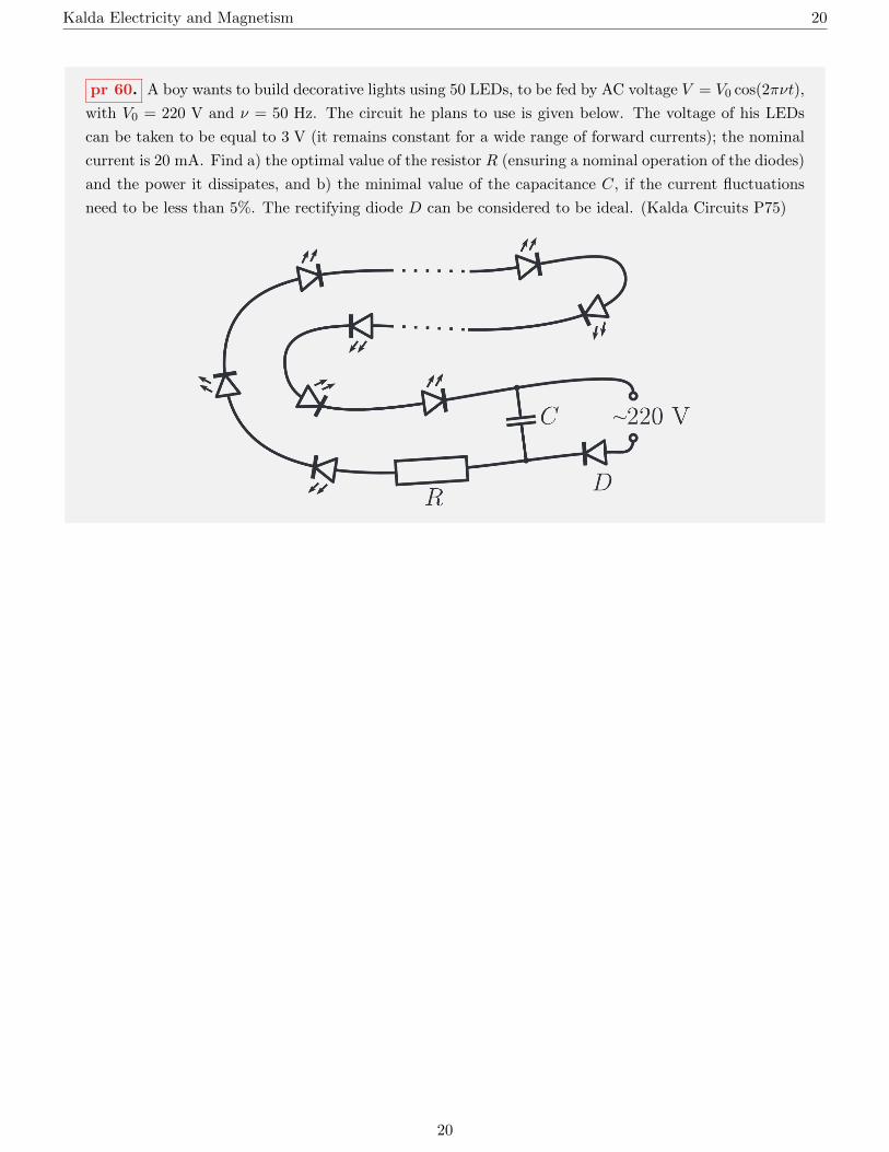
pr 60. A boy wants to build decorative lights using 50 LEDs, to be fed by AC voltage V = V0 cos(2πνt),
with V0 = 220 V and ν = 50 Hz. The circuit he plans to use is given below. The voltage of his LEDs
can be taken to be equal to 3 V (it remains constant for a wide range of forward currents); the nominal
current is 20 mA. Find a) the optimal value of the resistor R (ensuring a nominal operation of the diodes)
and the power it dissipates, and b) the minimal value of the capacitance C, if the current fluctuations
need to be less than 5%. The rectifying diode D can be considered to be ideal. (Kalda Circuits P75)
20

Kalda Electricity and Magnetism 21
3 Electrostatics
pr 61. Four identical point charges of charge q lie on the vertices of a square with side length L.
Determine the magnitude of the force acting on the charges.
pr 62. There are fixed point charges of q, 2q, 3q, . . . , 12q (q > 0) on a clock face, with each of the
charges on their respective hour. What time (hours and minutes) does the electric field vector at the
center of the clock point towards? Tip: Use symmetry and the fact that the sum of the vectors does not
depend on the order of the additions.
pr 63. Two point charges q1 and q2 are located a distance L from each other. Where should a third
charge be placed and what should its magnitude be in order to balance the first two charges? Tip: In
order to write a general answer for this problem, you should define a coordinate axes to determine the
locations of the charges and carefully consider the signs of the charges.
pr 64. A third point charge is placed in between two identical fixed point charges. Does that charge
remain in stable equilibrium if its charge has opposite sign to the two extreme charges? Note: Equilibrium
stability means that a small deviation from the equilibrium position results in a force that directs the
body back toward the equilibrium position.
pr 65. Two identical point charges of charge q are located a distance 2d from each other. Find the
maximum magnitude of the electric field on the perpendicular bisector of the line connecting these
charges. Note: If we plot the dependence y = f(x), then the point of the graph where f(x) acquires
its maximum value is where the tangent to the graph is momentarily horizontal (i.e. its slope is zero or
f ′(x) = 0).
pr 66. Prove that it is not possible to generate an electrostatic field in which the point charge remains
in stable equilibrium. Note: This is known as Earnshaw’s theorem.
pr 67. Find the electric field of a uniformly charged infinite plane having surface charge density σ.
pr 68. Find the field created by a parallel plate capacitor with surface charge densities ±σ. Also find
the force per unit area acting between the plates, or namely, the electrostatic pressure between the plates.
Note: From here on, unless otherwise indicated, assume that the dimensions of the capacitor plates are
much larger than their separation distance.
21
Kalda Electricity and Magnetism 22
pr 69. In nice weather, an electric field of magnitude 150 V/m is directed downwards near the Earth’s
surface. The field strength decreases with height and is 100 V/m at a height of 100 m. Determine the
average charge density in the atmosphere.
pr 70. Find the strength of the electric field generated by a thin, straight infinitely long wire at a
distance r from it, if the linear charge density along the wire is λ.
pr 71. Prove that the electric field inside a uniformly charged non-conducting hollow shell is zero.
pr 72. Find the electric field due to a uniformly charged non-conducting solid sphere of radius R having
volumetric charge density ρ.
pr 73. Find the strength of the electric field due to a non-conducting infinitely long charged cylinder
at a distance r from the axis of the cylinder. The volumetric charge density of the cylinder is ρ and the
radius of the cylinder is R.
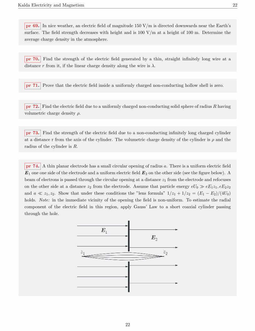
pr 74. A thin planar electrode has a small circular opening of radius a. There is a uniform electric field
E1 one one side of the electrode and a uniform electric field E2 on the other side (see the figure below). A
beam of electrons is passed through the circular opening at a distance z1 from the electrode and refocuses
on the other side at a distance z2 from the electrode. Assume that particle energy eU0 eE1z1, eE2z2
and a z1, z2. Show that under these conditions the ”lens formula” 1/z1 + 1/z2 = (E1 − E2)/(4U0)
holds. Note: in the immediate vicinity of the opening the field is non-uniform. To estimate the radial
component of the electric field in this region, apply Gauss’ Law to a short coaxial cylinder passing
through the hole.
22

Kalda Electricity and Magnetism 23
pr 75. a) Determine the electric field due to two non-conducting charged spheres of radius R in their
region of overlap. The volumetric charge densities of the spheres is ±ρ and the distance between the
centres of the spheres is d. b) Solve part a) if the two spheres are replaced by infinitely long parallel
cylinders.
pr 76. Consider a uniformly charged sphere of charge density ρ. Inside this sphere is a spherical cavity
located at a position r0 relative to the center of the sphere. Determine the electric field in the cavity.
pr 77. Show that the force acting between two spheres with uniform charge distribution is the same
as the force between two point charges (i.e. Q1Q2/(4πε0r2)), where Q1 and Q2 are the total charges on
the spheres and r is the distance between their centers.
pr 78. Determine the force between a uniformly charged infinitely long cylinder and a uniformly charged
sphere. The linear charge density of the cylinder is λ, the total charge found on the sphere is Q and r is
the distance from the centre of the sphere to the axis of the cylinder.
pr 79. Find the electrostatic pressure acting on the surface of a uniformly charged sphere if the surface
charge density of the sphere is σ.
pr 80. Find the force exerted by one hemisphere of a non-conducting uniformly charged sphere having
charge Q and radius R on the other hemisphere. Note: This problem is also in Griffiths.
pr 81. Determine the electric field at a distance r along the central axis of a dipole.
23

Kalda Electricity and Magnetism 24
pr 82. Prove expression 4 for an electric dipole. Note: Use the results of the previous problem to treat
an arbitrarily oriented dipole as a superposition of two perpendicular dipoles. Essentially, this means
adding additional fictitious charges ±q to a suitable points in space.
Expression 4 (also see the figure above) gives
Er =2p cos θ
4πε0r3, Eθ =
p sin θ
4πε0r3
where the quantity p =∑qir i is known as the dipole moment of a system of charges
pr 83. A parallel plate capacitor located in a vacuum is formed with two metal plates of area S. The
capacitor is then charged to a voltage U . Determine the strength of the electric field in the plane of the
plates at a distance r from the plates, where r is much larger than the dimensions of the plates.
pr 84. Find the torque acting on an electric dipole p when it is placed in an external electric field E .
pr 85. Calculate the potential energy of an electric dipole p in an electric field E .
pr 86. Determine the force acting between an electric dipole p and a point charge q if they are separated
by a distance r and the vector p is directed towards the point charge. Note: Here, a similar approach
to that in P81 can be used. It is also possible to use a virtual shift approach like the one in P85. This
problem gives an intermediate result for the more general formula Fx = p(∂E/∂x).
pr 87. Determine the force between two dipoles p1 and p2 if the distance between the dipoles is r.
pr 88. Estimate the frequency of oscillation of a polar molecule in an electric field of E = 30 kV/m.
We can model the molecule as a rigid dumbbell-shaped structure with length l ∼ 0.1 nm and mass
m ∼ 10−26 kg. The magnitude of the charges ±q on the atoms are 1.6× 10⁻¹⁹ C.
24
Kalda Electricity and Magnetism 25
pr 89. The space 0 < x < d has uniform charge density ρ (ρ > 0), and the space −d < x < 0 has
uniform charge density −ρ. There is no charge in the regions −∞ < x < −d and d < x < ∞. In the
region x > d, an electron with mass m and charge −e moves with its velocity vector pointed directly
towards the charged space. What is the minimum initial velocity that the electron must have if it is able
to pass through the charged space?
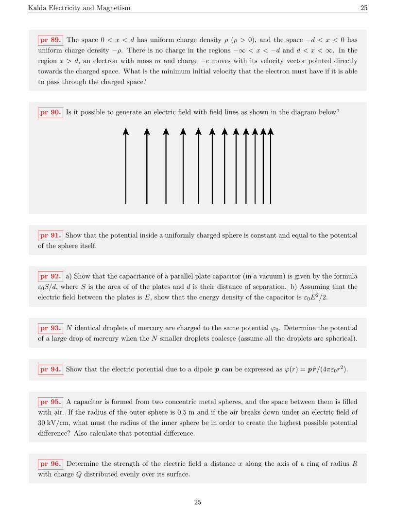
pr 90. Is it possible to generate an electric field with field lines as shown in the diagram below?
pr 91. Show that the potential inside a uniformly charged sphere is constant and equal to the potential
of the sphere itself.
pr 92. a) Show that the capacitance of a parallel plate capacitor (in a vacuum) is given by the formula
ε0S/d, where S is the area of of the plates and d is their distance of separation. b) Assuming that the
electric field between the plates is E, show that the energy density of the capacitor is ε0E2/2.
pr 93. N identical droplets of mercury are charged to the same potential ϕ0. Determine the potential
of a large drop of mercury when the N smaller droplets coalesce (assume all the droplets are spherical).
pr 94. Show that the electric potential due to a dipole p can be expressed as ϕ(r) = pr/(4πε0r2).
pr 95. A capacitor is formed from two concentric metal spheres, and the space between them is filled
with air. If the radius of the outer sphere is 0.5 m and if the air breaks down under an electric field of
30 kV/cm, what must the radius of the inner sphere be in order to create the highest possible potential
difference? Also calculate that potential difference.
pr 96. Determine the strength of the electric field a distance x along the axis of a ring of radius R
with charge Q distributed evenly over its surface.
25

Kalda Electricity and Magnetism 26
pr 97. Determine the radius of an electron assuming that the mass of an electron (me = 9.1×10⁻³¹ kg)
is due to the electrostatic energy of its charge (Π = mc2). In our simple model, you may assume that
the charge of the electron (e = −1.6× 10⁻¹⁹ C) is evenly distributed over its ”surface”.
pr 98. Two metal spheres with radii R1 and R2 are spaced a very far distance apart. If both spheres
initially have charge q, what will the charges on the spheres be once they are connected by a wire?
pr 99. A point charge q is placed a distance h above an infinite planar conductor. Determine the
surface charge density σ induced on the surface of the conductor.
pr 100. A metal sphere with radius r is given charge q. The sphere is connected to the ground with a
long wire of resistance R. Determine the initial current through the wire.
pr 101. A metal sphere of radius r is located inside a larger metal sphere of radius R. The two spheres
are concentric, and the smaller sphere is grounded by a long wire (that passes through a small opening
on the surface of the larger sphere). The larger sphere has no contact with the other sphere or the
grounding wire. a) The outer sphere is given a charge Q. What charge is induced on the smaller sphere
as a result? b) Determine the capacitance of the spheres.
pr 102. A point charge q is located a distance r from the center of a metal sphere of radius R. What
is the potential of the sphere?
pr 103. A point charge q is at a distance h above the surface of a conductor in the shape of an infinite
plane. What is the force acting on this point charge?
pr 104. A metal sphere of radius R is placed in a homogeneous electric field E0. Determine the charge
density on the surface of the sphere and the electric field in the space around the sphere. Note: The field
outside the sphere due to the surface charge density is similar to the field caused by a dipole placed at
the center of the sphere (see P94).
pr 105. A metal cylinder of radius R is placed in a homogeneous electric field E0 with its axis perpen-
dicular to the field. Determine the charge density induced on the surface of the cylinder and the electric
field in the space around the cylinder.
26

Kalda Electricity and Magnetism 27
pr 106. A charge q is located at a distance h from the center of a grounded metal sphere of radius R.
Find the force acting on the charge.
pr 107. Solve the previous problem if the sphere is not grounded. Tip: The solution to P106 only
needs to be slightly improved.
pr 108. The two plates in a parallel plate capacitor each have area S and are separated by a distance
d. Both plates are grounded. A point charge q is placed between the two plates at a distance x from the
first plate. How much charge accumulates on each plate?
pr 109. A dielectric with dielectric constant κ is inserted between the plates of a parallel plate capacitor
with area S and separation d. a) Find the capacitance of the capacitor; b) Find the force acting between
the plates of the capacitor when a potential difference of U is applied across the plates
pr 110. A parallel plate capacitor is immersed in a non-conductive fluid with dielectric constant κ.
Determine the force between the plates if the area of the plates is S, their separation is d, and the charges
on them are ±Q.
pr 111. A dielectric slab with uniform thickness and dielectric constant κ is placed in a homogeneous
electric field E0, with which the plate forms an angle θ. Determine the electric field inside the plate and
the charge density on the surface of the plate.
pr 112. An infinitely long dielectric cylinder with dielectric constant κ is placed in a homogeneous
electric field E0. Determine the electric field inside the cylinder if the axis of the cylinder: a) is parallel
to E0; b) lies across E0.
pr 113. Consider a dielectric sphere of radius R and dielectric constant κ. Determine the field inside
the sphere and the surface charge density on the surface of the sphere.
pr 114. A point charge q is kept at a distance h from the line separating two infinite dielectric planes.
The dielectric constants of the planes are κ1 and κ2 respectively. Find the electric field in each dielectric.
pr 115. Determine the force acting on a dielectric sphere of radius R and dielectric constant κ in an
inhomogeneous electric field E(r). Note: See problem 113 and problem 86.
27

Kalda Electricity and Magnetism 28
4 Magnetostatics
pr 116. Determine the magnetic field at a distance x along the axis of a loop of current. The loop has
radius R and has a current I running through it.
pr 117. Determine the magnetic field due to an infinite sheet of current. The current density (A/m)
is everywhere and equal to α.
pr 118. Determine the magnetic field at a distance r from an infinitely long straight wire. The current
in the wire is I.
pr 119. Determine the magnetic field at a distance r from the axis of a cylindrical conductor if the
current density over the cross-section of the conductor is uniform and equal to J . The radius of the
cylinder is R.
pr 120. A solenoid is a thin wire that is tightly and evenly wrapped in a cylindrical manner. Consider
a long solenoid with n turns per unit length along its axis with a current I passing through it. Such a
solenoid is the magnetic analogue of a parallel plate capacitor. Show that: a) the magnetic field inside
the solenoid is homogeneous and oriented in the axial direction; b) there is no magnetic field outside the
solenoid, and c) the magnetic field inside the solenoid is given by B = µ0nI.
pr 121. The figure below depicts two different wires each with current I running through it (straight
branches run to infinity). In each case, determine the magnetic force at the point marked with a black
dot.
pr 122. Determine the magnetic field at the end of a long solenoid. A current I runs through the
solenoid, which has n turns per unit length.
28

Kalda Electricity and Magnetism 29
pr 123. Determine the magnetic field in the cavity formed by the intersection of two straight, infinitely
long, cylindrical conductors as shown in the figure below. The current densities in each of the conductors
are equal but in opposite directions (±J), the radius of both conductors is R, and the distance between
their centers is d.
pr 124. Determine the force per unit length between two infinitely long straight parallel wires if the
currents in the wires are I1 and I2 and the distance between the wires is r.
pr 125. A charge Q is evenly distributed over a sphere of radius R. The sphere rotates at an angular
velocity ω about an axis through its center. Determine the magnetic moment of such a system. Note:
Divide the surface of the sphere into infinitely thin layers and add the area of a thin spherical segment
∆S = 2πR∆h.
pr 126. A permanent magnet is hung by a thread. Its magnetic moment is p (which lies on a horizontal
plane) and its moment of inertia from the attachment point of the thread relative to the vertical axis
is I. Determine the oscillation period of small-amplitude oscillations when a homogeneous horizontal
magnetic field B is generated in space.
pr 127. Two permanent magnets (with magnetic moments p1 and p1) are placed a distance r from
each other (where r is much greater than the dimensions of the magnets). Determine the force acting
between the magnets.
pr 128. The ratio of the magnetic moment of a particle to its angular momentum is known as the
gyromagnetic ratio of that particle. Find the gyromagnetic ratio for the orbital motion of an electron
using the Bohr model. Note: According to Bohr’s theory, the electron orbits the nucleus in a circular
orbit where the orbital momentum of the electron is quantized: mvr = n~, where n = 1, 2, 3 . . . .
29

Kalda Electricity and Magnetism 30
pr 129. The magnetic moment of an iron atom is given by p = 2.2µB, where µB = e~/2me ≈9.27 × 10⁻²⁴ A m2 (also known as the Bohr magneton). The distance between adjacent atoms in the
cubic crystal lattice of iron is d = 2.3 A. What is the maximum magnetic field that can be generated by
magnetized iron in the absence of an external magnetic field?
pr 130. Determine the magnetic field inside an infinitely long solenoid if the solenoid is filled with a
substance with relative magnetic permeability µ. The ampere-turns per unit length of the solenoid is
given by nI.
pr 131. A spherical magnet with relative magnetic permeability µ is placed in a homogeneous magnetic
field B0. Determine the magnetic field inside the sphere. Tip: the magnetic field of a uniformly
magnetized sphere outside the sphere is similar to the field produced by a magnetic dipole placed in the
center of the sphere.
pr 132. An electromagnet used in a laboratory consists of an iron core (with relative magnetic perme-
ability µ) and a wire wound around it N times, as shown in the diagram below. The width d of the air
gap is much smaller than the thickness of the core. If the length of the core is l and the current in the
wire is I, determine the magnetic field in the air gap of the core.
30

Kalda Electricity and Magnetism 31
pr 133. The electromagnet shown below consists of a core (1) and and an anchor (2); the relative
permeability of each is µ. A wire is wrapped N times around the core, through which a current I is
passed. The cross-sectional area of the core and anchor is S and it has total length l. Find the force by
which the core holds the anchor. Note: A virtual shift method can be used here. However, note that
changing the distance between the core and anchor induces an emf in the coil.
pr 134. Parallel to and at a distance h above the surface of an infinite planar superconductor is an
infinitely long straight wire with current I running though it. Determine the force acting on a unit length
of this wire.
31

Kalda Electricity and Magnetism 32
5 Electromagnetic Induction
pr 135. One method of measuring magnetic field is as follows. A small coil is inserted into the magnetic
field with its axis parallel to B . The terminals of the coil are connected to a ballistic galvanometer, which
measures the amount of charge passed through it. The coil is then quickly rotated 180. How much
charge passes through the galvanometer if the area of the coil is S, the number of turns is N , and the
resistance of the coil is R?
pr 136. Two horizontal infinitely long parallel metal rails with negligible resistance are placed a distance
l from each other. The rails are connected to a capacitor of capacitance C and voltage U0. If there is a
homogeneous vertical magnetic field of magnitude B , a) what is the maximum velocity the rod reaches,
and b) what is the maximum possible efficiency of such an ”electromagnetic cannon” (i.e. how much of
the energy stored in the capacitor can be converted into kinetic energy in the rod)?
pr 137. A dielectric ring of mass m is attached by spokes of negligible mass to an axis around which
it can rotate frictionlessly. A charge Q is evenly distributed over the ring. Initially, the (stationary)
ring is located along the axis of a homogeneous magnetic field B . After some time, the magnetic field is
switched off. What is the final angular velocity of the ring?
pr 138. In the circuit below, switch K has been closed for a long time and all the bulbs have the same
brightness. For each of the bulbs, how many times does the current through the bulb change immediately
after opening switch K.
32

Kalda Electricity and Magnetism 33
pr 139. In the circuit shown below, switch K has been open for a long time. a) What is the ammeter
reading immediately after closing the switch? b) The switch is kept closed until the current reaches a
steady state. What is the ammeter reading now? c) After the current has reached a steady state, what
is the ammeter reading immediately after opening the switch?
pr 140. Circuit element E with I−V dependence as shown in the graph below is connected to a circuit
an inductor and battery. How does the voltage on element E change over time? Determine time steps.
pr 141. A battery with emf E = 12 V is charged by a DC voltage source as shown in the figure below.
The inductance in the coil is L = 1 H and it has negligible resistance. The diode can be assumed to be
ideal. Switch K closes and opens periodically, alternating from being closed for time τ1 to being open
for time τ2, where τ1 = τ2 = 0.01 s. Determine the average charging current.
33

Kalda Electricity and Magnetism 34
pr 142. Determine the inductance of a solenoid if its diameter is much smaller than its length l. The
number of turns is N and the cross-sectional area of the solenoid is S. The solenoid is wound around a
ferromagnetic core with relative magnetic permeability µ.
pr 143. Assuming that the work done to generate current in a solenoid LI2/2 goes into the energy of
its magnetic field, show that the energy density of the magnetic field is given by B2/2µ0.
pr 144. Determine the inductance of a straight wire of length l and radius a.
pr 145. Show that the mutual inductances L12 and L21 are always equal. Note: Find the energy of the
coupled circuits if the currents I1 and I2 flow through them. To do this, calculate the work the current
sources need to do in order to generate the currents and show that the result is unambiguous only under
the condition L12 = L21.
pr 146. Show that M ≤√L1L2, where M is the mutual inductance and L1, L2 are the self-inductances
of the coupled circuits. Note: Show that for M >√L1L2, conservation of energy is violated, namely
that increasing the current in one of the circuits induces an emf in the circuit, which causes the current
to increase further (E1dI1 > 0).
pr 147. A toroid consists of a thin wire wrapped around a torus. Let the major and minor radii of the
toroid be R and r, respectively, where r R and let the number of turns of the wire be N . Determine
the mutual inductance between the toroid and a straight wire. Prove that the equation L12 = L21 is
valid for this system.
pr 148. Determine the mutual inductance between two coils wrapped around a common toroidal core.
The first coil has N1 turns and the second has N2 turns. The length of the core is l and has cross-sectional
area S and relative magnetic permeability µ.
pr 149. Two coils are wound around a common ferromagnetic core. The first has N1 turns and the
second N2 turns, where N1/N2 = n. The coils have negligible resistance. The ends of the second coil are
connected to resistor R, and a DC voltage source of voltage U is connected to the terminals of the first
coil. Show that the power dissipated by the resistor is given by n2U2/R.
34
Kalda Electricity and Magnetism 35
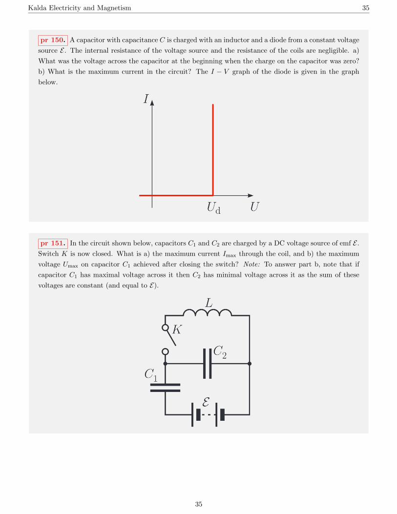
pr 150. A capacitor with capacitance C is charged with an inductor and a diode from a constant voltage
source E . The internal resistance of the voltage source and the resistance of the coils are negligible. a)
What was the voltage across the capacitor at the beginning when the charge on the capacitor was zero?
b) What is the maximum current in the circuit? The I − V graph of the diode is given in the graph
below.
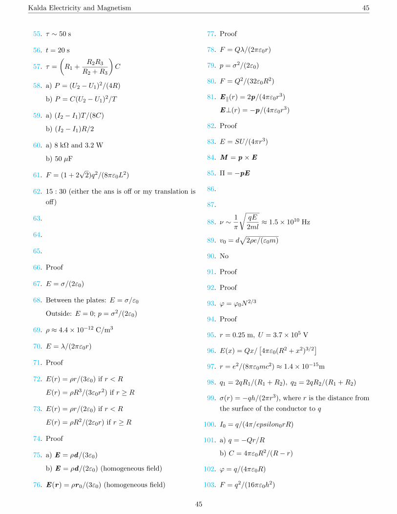
pr 151. In the circuit shown below, capacitors C1 and C2 are charged by a DC voltage source of emf E .
Switch K is now closed. What is a) the maximum current Imax through the coil, and b) the maximum
voltage Umax on capacitor C1 achieved after closing the switch? Note: To answer part b, note that if
capacitor C1 has maximal voltage across it then C2 has minimal voltage across it as the sum of these
voltages are constant (and equal to E).
35

Kalda Electricity and Magnetism 36
6 AC Circuits
pr 152. A heater with power 30 W is designed for a mains voltage of 220 V. How large of a capacitor
should be connected in series with the heater to reduce its power to 20 W? Do not consider the
temperature-dependence of the heater’s resistance into account.
pr 153. [IPhO 1982] A fluorescent lamp is connected to a mains electricity supply as shown in the figure
below. The mains frequency is 50 Hz and supplies an emf of 228.5 V. The current in the circuit is 0.60 A,
the voltage across the lamp is 84 V, and the resistance in the coil is 26.3 Ω. Assume that the fluorescent
lamp is ohmic. Starter S is a switch that closes when the lamp is switched on, but quickly opens again
and remains open when the lamp is lit. a) What is the inductance L of the coil? b) Determine the phase
shift ∆φ between the voltage and the current. c) What power P is dissipated by the circuit? d) It is
sometimes necessary to compensate for the reactive current resulting from the simultaneous use of many
fluorescent lamps (see P154). A capacitor of what capacitance should be connected in series with the
coil in order to reverse the phase shift? (Kalda Circuits P87)
pr 154. A cottage receives power from a substation via a long single-phase overhead power line. As
a result, in addition to an electric meter, the house has a voltmeter to check the voltage reaching the
house. After returning the the cottage after a three month absence, you discover that although all
your appliances (including your lights) have been switched off, the transformer you were using had been
consuming power. However, this energy consumption was not shown on your electric meter, and you
want to determine how many kilowatt-hours of energy you didn’t pay Eesti Energia for heating the air
with an overhead line. To do this, you took three separate voltage readings: (1) Ut = 234.0 V if only
the transformer is connected to the mains; (2) U0 = 236.0 V if everything (including the transformer)
is switched off; and (3) Ur = 219.6 V if the transformer is off but the electric radiator is on. You also
determined, for the third case, that the power consumption of the radiator was Pr = 1200 W. Similarly,
you recorded that if only the transformer is switched on, it consumes power Pt = 5 W. How many
kilowatt-hours of energy did the transformer/overhead line consume during your absence?
36

Kalda Electricity and Magnetism 37
pr 155. The figure below is also known as a Maxwell bridge, a circuit used to determine the inductance
L and resistance R of the inductor. To do this, resistors R1, R2, RC and capacitor C are adjusted until
the voltmeter V reads 0. Determine L and R in terms of R1, R2, RC , and C.
pr 156. The figure below shows a circuit that can be used to change the phase of an alternating signal.
Show that, for a negligible output current, the output voltage is the same as the input voltage, but with
a phase shift of 2 arctan(ωRC) (or 2 arctan(−1/ωRC)). (Kalda Circuits P95)
37

Kalda Electricity and Magnetism 38
pr 157. The circuit in the figure below is supplied with an AC voltage source with RMS voltage U .
Determine the power dissipated in the circuit. Note: The power dissipated can be found in two ways:
by summing the individual powers I2R on all resistors or by using formula 9 for the whole circuit.
pr 158. The relationship between the voltages and currents of the primary and secondary coils of a
transformer are generally very complex. However, real transformers are often close to an ideal trans-
former, which has the following properties: 1) The inductances L1 and L2 of the coils are very high; 2)
The coupling between the primary and secondary coils is maximal; 3) The resistances of the coils are
negligible; and 4) Losses in the core (hysteresis, eddy currents, etc.) are negligible. Show that in this
case all currents and voltages have the same phase and the following equations hold:
U2
U1= n,
I2I1
=1
n,
where n is the ratio between the number of turns in the secondary coil to the number of turns in the
primary coil.
pr 159. In the LC circuit shown below, L1 = 10 mH, L2 = 20 mH, C1 = 10 nF, and C2 = 5 nF. At
some point in time, the current through L1 was equal to I1 = 0.1 A and the voltage across C1 at the
same time was U0 = 40 V. What is the amplitude of current oscillations in coil L2?
38

Kalda Electricity and Magnetism 39
pr 160. Determine the natural oscillation frequency of the LC circuit shown below.
pr 161. Determine the natural oscillation frequencies of the LC circuit shown below. Note: The
equation a2 = b2 satisfies both a = b and a = −b. (Kalda Circuits P99)
39

Kalda Electricity and Magnetism 40
7 Movement of Charged Particles in Electric and Magnetic Fields
pr 162. An electron with velocity v moves in a homogeneous magnetic field B , where v⊥B . Determine
the radius of the electron’s trajectory.
pr 163. A beam of electrons is emitted from a point source. The magnitudes of the velocities v of the
electrons are equal, but they are scattered by an angle of up to α with respect to the direction of the
homogeneous magnetic field B in the space, where α 1. At what distance from the point source does
the electron beam focus again?
pr 164. Two parallel electrodes (a cathode and an anode) are located a distance d from each other
in a vacuum. A positive potential U is applied from the cathode to the anode. From the surface of
the cathode, an electron with initial velocity zero is accelerated by the electric field. How strong of a
magnetic field B perpendicular to the electric field must be generated between the electrodes so that the
electron no longer reaches the anode?
pr 165. Two coaxial cylindrical conductors are located in a vacuum. The inner (cathode) radius is a
and the outer (anode) radius is b. The anode is given a positive potential U with respect to the cathode.
There is a homogeneous magnetic field B in the space between the cylinders. An electron begins to move
with initial speed zero from the surface of the cathode due to the electric field. Determine the critical
value of B for which the electron no longer reaches the anode.
pr 166. An electron with initial velocity v0 travels in a homogeneous electric and magnetic field. The
vectors v0,E , and B are all perpendicular to each other and v0 = B ×E . What is the trajectory of the
electron? What is its average speed 〈v〉? Assume that E/B c and v c.
pr 167. In metals, each atom donates, on average, one valence electron. Determine the drift velocity
of electrons in copper wire with current density 5 A/mm2. The density of copper is 8900 kg/m3 and its
molar mass is 63.5 g/mol.
pr 168. Two identical metal spheres of radius r are placed in a homogeneous conductive medium with
resistivity ρ. The distance between the spheres is much larger than their radius. What is the resistance
between the spheres?
40

Kalda Electricity and Magnetism 41
pr 169. One problem in determining the resistivity ρ of a semiconductor is the unknown voltage drop
across the contacts. This problem can be solved with the following method, which we analyze here using
a semi-infinite thin plate (with thickness h) for simplicity. Let the four contacts be soldered to the edge
of the plate as shown in the diagram below. a) Current I passes though contacts A and B. Show that a
voltmeter connected between contacts C and D measures a voltage of
U =Iρ
πhln
((a+ b+ c)b
(a+ b)(b+ c)
).
Let the ratio U/I be RAB,CD. b) Show analogously that when current I passes through contacts B and
C, then
RBC,AD =ρ
πhln
((a+ b)
(b+ c)ac
)c) Show that
exp(πhRAB,CD/ρ) + exp(πhRBC,AD/ρ) = 1
The obtained relationship allows us to determine ρ after measuring RAB,CD and RBC,AD.
It is not specified what a, b, and c are, but it is likely that a = AB, b = BC, and c = CD
pr 170. With the method described below, it is possible to measure the resistivity of a material without
attaching contacts to the material. A disk-shaped piece of material is placed in a homogeneous magnetic
field generated inside a solenoid so that the axis of the disk is parallel to the axis of the solenoid. The
solenoid is supplied by an AC source with frequency ω such that B(t) = B0 cos(ωt). The disk has radius
R and thickness d. Determine the resistivity of the disk if the disk dissipates power P . Note: You may
need the formula⟨sin2 α
⟩=⟨cos2 α
⟩= 1/2 and the integral
∫xndx = xn+1/(n+ 1).
pr 171. A metal plate is located in a homogeneous magnetic field B that is perpendicular to the surface
of the plate. Determine the drag force caused by the eddy currents in the plate as the plate moves at a
speed v perpendicular to B . The area of the plate is S, its thickness is d, and it has resistivity ρ. Note:
There are several ways to get an approximate answer. One possibility is to use conservation of energy
by estimating the heat generated in the plate due to the eddy currents.
41

Kalda Electricity and Magnetism 42
pr 172. Determine the strength of the transverse electric field due to the Hall effect for the situation
shown in the image below. Assume that there is only one type of charge carrier in the material, with
charge q and charge carrier density n.
pr 173. A semiconductor that measures the strength of a magnetic field using the Hall effect is called
a Hall sensor. Construct a circuit diagram for a wattmeter if a Hall sensor, solenoid, and voltmeter are
used.
pr 174. An electromagnetic pump can be used to pump liquids with good electrical conductivity (a
schematic is shown in the figure below). A liquid with resistivity ρ moves at speed v through the pump.
The vectors v ,B , and E are all mutually perpendicular. a) Show that the fluid is subjected to a force
F = B2(u − v)/ρ, where u = E × B/B2. b) Show that the maximum efficiency of the pump is 0.5.
Assume that the magnetic field creates a permanent magnet and that edge effects are negligible.
42

Kalda Electricity and Magnetism 43
pr 175. A homopolar motor consists of a copper disk attached to a shaft that rotates in a homogeneous
magnetic field B directed parallel to the axis of the disk. Current flows into the disk through the shaft
and exits through the side of the disk. The radius of the shaft is a, the radius of the disk b, and
the thickness of the disk h. The resistivity of the disk is ρ. a) Determine the torque M exerted on
the disk by the magnetic field when a current I flows through it. b) Determine the heat P dissipated
by the disk when a current I flows through it. c) Find the potential difference U between the axis
and the edge of the disk when it is rotating at an angular velocity ω. d) Show that conservation of
energy holds in the form V I = Mω + P . Note: The problems requires taking a few simple integrals:∫xdx = x2/2,
∫(1/x)dx = lnx.
43

Kalda Electricity and Magnetism 44
8 Answers
1. I1 = 1.5 A; I2 = 1.7 A
2.
3.
4. Increases ≈ 1.14 times
5. R = (2/9)R0
6. ρ ≈ 24 Ω m
7. R ≈ 14 Ω
8. 900 Ω
9. 12 V
10. 26/7 Ω
11. I = 0.5 A
12.
13.
14. I4 = 3 A, I3 = 2 A
15.
16. R = 1 Ω
17. Proof
18.
19.
20.
21.
E =
∑i
(Eiri
)∑
i
(1
ri
) , r =
(∑i
1
rI
)−1
22. Same as P21
23.
24. R = 11/6 Ω
25.
26. R = 1 Ω
27. 4 A
28. 1 mA, 4V
29. R = R12
(1 +
√1 + 4R2/R1
)30. r′ = R
2
(1 +
√1 + 4R/r
), E ′ = E
31. R = 1/3 Ω
32. R = 1/3 Ω
33. R = 1/2 Ω
34.
35. 0.75 mW, 0 W, 0 W
36. I ≈ 8 mA
37.
38. P ≈ 0.48 W
39. U0 ≈ U1 + I1R
40. ∼ 3 times
41. I = 2.97 mA
42. Proof
43. l ≈ 12 cm, d ≈ 5.8 µm, T ≈ 2650 K
44.
45.
46. Q = CE2/2
47. Q ≈ 123 µJ
48. Proof
49. Q = 2CE2/27
50.
51. F ≈ 6.4 µN
52. M = ε0R2U2/(4d)
53. F = (κ− 1)ε0aU2/(2d)
54. h = (κ− 1)ε0U2/(2d2ρg)
44
Kalda Electricity and Magnetism 45
55. τ ∼ 50 s
56. t = 20 s
57. τ =
(R1 +
R2R3
R2 +R3
)C
58. a) P = (U2 − U1)2/(4R)
b) P = C(U2 − U1)2/T
59. a) (I2 − I1)T/(8C)
b) (I2 − I1)R/2
60. a) 8 kΩ and 3.2 W
b) 50 µF
61. F = (1 + 2√
2)q2/(8πε0L2)
62. 15 : 30 (either the ans is off or my translation is
off)
63.
64.
65.
66. Proof
67. E = σ/(2ε0)
68. Between the plates: E = σ/ε0
Outside: E = 0; p = σ2/(2ε0)
69. ρ ≈ 4.4× 10⁻¹² C/m3
70. E = λ/(2πε0r)
71. Proof
72. E(r) = ρr/(3ε0) if r < R
E(r) = ρR3/(3ε0r2) if r ≥ R
73. E(r) = ρr/(2ε0) if r < R
E(r) = ρR2/(2ε0r) if r ≥ R
74. Proof
75. a) E = ρd/(3ε0)
b) E = ρd/(2ε0) (homogeneous field)
76. E(r) = ρr0/(3ε0) (homogeneous field)
77. Proof
78. F = Qλ/(2πε0r)
79. p = σ2/(2ε0)
80. F = Q2/(32ε0R2)
81. E‖(r) = 2p/(4πε0r3)
E⊥(r) = −p/(4πε0r3)
82. Proof
83. E = SU/(4πr3)
84. M = p ×E
85. Π = −pE
86.
87.
88. ν ∼ 1
π
√qE
2ml≈ 1.5× 10¹⁰ Hz
89. v0 = d√
2ρe/(ε0m)
90. No
91. Proof
92. Proof
93. ϕ = ϕ0N2/3
94. Proof
95. r = 0.25 m, U = 3.7× 10⁵ V
96. E(x) = Qx/[4πε0(R
2 + x2)3/2]
97. r = e2/(8πε0mc2) ≈ 1.4× 10⁻¹⁵m
98. q1 = 2qR1/(R1 +R2), q2 = 2qR2/(R1 +R2)
99. σ(r) = −qh/(2πr3), where r is the distance from
the surface of the conductor to q
100. I0 = q/(4π/epsilon0rR)
101. a) q = −Qr/R
b) C = 4πε0R2/(R− r)
102. ϕ = q/(4πε0R)
103. F = q2/(16πε0h2)
45

Kalda Electricity and Magnetism 46
104. Er =
(2R3
r3+ 1
)E0 cos θ
Eθ =
(R3
r3− 1
)E0 sin θ
σ(θ) = 3ε0E0 cos θ, where θ is the angle between
the vectors E0 and r
105. Er =
(R2
r2+ 1
)E0 cos θ
Eθ =
(R2
r2− 1
)E0 sin θ
σ(θ) = 2ε0E0 cos θ
106. F = − hRq2
4πε0(h2 −R2)2
107. F = − R3(2h2 −R2)q2
4πε0h3(h2 −R2)2
108. q1 = −q(1− x/d), q2 = −qx/d
109. a) C − κε0S/d
b) F = κ2ε0SU2/(2d2)
110. F = −Q2/(2κε0S)
111. E‖ = E0 sin θ
E⊥ = E0 cos(θ)/κ
σ = E0 cos(θ)(κ− 1)/(κε0)
112. a) E = E0
b) E = 2E0/(κ+ 1)
113. E =3E0
2 + κ
σ(θ) = 3κ− 1
κ+ 2ε0E0 cos θ
114. E1 =q
4πε0r21r1 +
q′
2πε0r22r2
E2 =q′′
4πε0r21r1
q′ =κ1 − κ2κ1 + κ2
q, q′′ =2κ1
κ1 + κ2q
115. x-component of the force:
Fx = 2πε0R3κ− 1
κ+ 2
∂
∂xE2
116. B(x) = 12µ0R
2I/(R2 + x2)3/2
117. B = µ0α/2
118. B = µ0I/(2πr)
119. B(r) = µ0Jr/2 if r < R
B(r) = µ0JR2/(2r) is r ≥ R
120. Proof
121.
122. B = 12µ0nI
123. B = (µ0/2)J × d (homogeneous vertical field)
124. F = µ0I1I2/(2πr)
125. p = QR2ω/3
126. T = 2π
√I
pB
127. F = − 3µ02πr4
(p1r)(p2r)
128. p/L = −e/(2m)
129. B = µ0p/d3 ≈ 2.1 T
130. B = µµ0nI
131. B = 3µB0
2 + µ
132. B = µ0NI/(l/µ+ d)
133. F = −µ2µ0SN2I2/l2
134. F = µ0I2/(4πh)
135. q = 2BNS/R
136. a) vmax =BlCU0
m+B2l2C
b) η = 0.25
137. ω = BQ/(2m)
138. The current though E1 doubles, and the currents
though the other two lamps remain the same
139. The ammeter reads 0 in all cases
140.
141. Icenter =U20 r1
2L(E − U0)(r1 + r2)≈ 8.9 mA
142. L = µµ0SN2/l
143. Proof
46

Kalda Electricity and Magnetism 47
144. L ∼ µ0l ln(l/a)
145. Proof
146. Proof
147. M = µ0Nr2/(2R)
148. M = µµ0N1N2S/l
149.
150. b) U = 2(E − Ud)
151. a) Imax =C1E√
L(C1 + C2)
b) Umax = E(
1 +C1
C1 + C2
)152. C ≈ 2.8 µF
153. a) L = 1.09 H; b) ∆φ = 64.1;
c) P = 59.9 W; d) C = 4.6 µF
154.
155. L = R1R2C, R = R1R2/RC
156. Proof
157. 3
(U2
R
)(C2ω2R2 + 1
C2ω2R2 + 9
)158. Proof
159.
160.
161. ω =
√5± 1
2√LC
162. R = mv/(eB)
163. L = 2πmv/(eB)
164. B = (√
2mU/e)/d
165. B =2b
b2 − a2
√2mU
e
166. r(t) = 〈v〉 t + R cos(ωt)v0 + R sin(ωt)E , where
R = mv0/(eB), ω = v0/R = eB/m and 〈v〉 =EB v0. The resulting trajectory is also known as a
cycloid
167. 0.37 mm/s
168. R = ρ/(2πr)
169. Proof
170. ρ = πR4B20ω
2/(16P )
171. F ∼ B2vSd/ρ
172. E = (1/nq)B × J
173.
174. Proof
175. a) M = BI(b2 − a2)/2
b) P = I2ρ ln(b/a)/(2πh)
c)ωB(b2 − a2)
2+Iρ ln(b/a)
2πh
d) Proof
47