ELECTROYANNNTIC I~NRFERENCE/ELECPRO~~IC COMPATIBILITY ...€¦ · EM1 conditions to which civil...
16
ELECTROYANNNTIC I~NRFERENCE/ELECPRO~~IC COMPATIBILITY Robert W. Borek Principal Engineer SPABTA, Inc. Lancaster, CA 93535 US 27.0 INTRODUCTION Ideally, Electronagnetic Interference/Electromagnetic Compatibility (BNI/EMC) testing should have been completed before an aircraft makes its initial flight. HOWeVer, it is almost inevitable that problems Will occur during the ensuing flight test program. MOreOVer, the Flight Test Engineer (FTE) Will be involved in the ground testing of the aircraft. This Section provides *orne background information on F&lI/ENC for the novice FTE involved in these disciplines. Furthermore, it identifies *orneof the standards and specifications used for developing test objectives and procedures for FMI testing. 'l'he discussions are based primarily on existing military requirements. This "as done with the supposition that industrial and commercial specifications may "ary from country to country, whereas the referenced military documents are uniformly related and generally obtainable. HOWeVer, the one exception is a set of civil standards that are used a11 over the world. These standards are continually updated and thoroughly address the EM1 conditions to which civil aircraft are subjected. [27-11 Further, this Section describes the major sources of EM1 and the broad range of system-subsystem BNI/BMC testing, typical test equipment, and the facilities generally used. In addition, *orne basic BM1 precautions to be taken in designing aircraft and instrumentation systems are discussed. 17.1 THE PAILOSOPHY OF STANDARDS AND SPECIFICATIONS Standards and specifications bave been written to establish the EMC performance characteristics that individual system installations must meet. Standards and specifications differ in that a standard is a general guideline from which specifications may be derived. A specification is a document usually containing numerical details to which adherence is a Contract"a1 requirement. The philosophy of writing general specifications rather than specific "tailored" specifications is that if the design of each 'black box" adheres to the specification, BNC Will be achieved. Although specifications should not be unquestionably relied upon, they do provide a baseline useful in system design. As a result they are widely used and often quoted. One concept of widespread importance in the use of standards and specifications is that of the EM1 safety margin (EMISM) which is defined as the ratio between the susceptibility threshold and the interference present on a critical test point or signal line. The ENISM concept applies to both conducted and radiated interference. Conducted interference paths are quite well defined, whereas the radiated signal received by a susceptor depends upon its distance as well as its physical orientation relative to the source. A greater safety margin, therefore, may be required for radiation coupling than for conduction. [27-21 27.2 THE ROLE OF TEE FLIGHT TEST ENQINENR The complexity of the problems created by electromagnetic interference has increased greatly in recent years. Although consideration of the EM1 problem has not been neglected throughout the development of individual electrical and Paper published by AGARD as par, of AGARDograph 3W Flight Tes: Techniques Suies - Volume 14. September 1995, entitled “lnrroducrion fo Flighl Test En@weNng “.
Transcript of ELECTROYANNNTIC I~NRFERENCE/ELECPRO~~IC COMPATIBILITY ...€¦ · EM1 conditions to which civil...

ELECTROYANNNTIC I~NRFERENCE/ELECPRO~~IC COMPATIBILITY
Robert W. Borek Principal Engineer
SPABTA, Inc. Lancaster, CA 93535
US
27.0 INTRODUCTION
Ideally, Electronagnetic Interference/Electromagnetic Compatibility (BNI/EMC) testing should have been completed before an aircraft makes its initial flight. HOWeVer, it is almost inevitable that problems Will occur during the ensuing flight test program. MOreOVer, the Flight Test Engineer (FTE) Will be involved in the ground testing of the aircraft. This Section provides *orne background information on F&lI/ENC for the novice FTE involved in these disciplines. Furthermore, it identifies *orne of the standards and specifications used for developing test objectives and procedures for FMI testing. 'l'he discussions are based primarily on existing military requirements. This "as done with the supposition that industrial and commercial specifications may "ary from country to country, whereas the referenced military documents are uniformly related and generally obtainable. HOWeVer, the one exception is a set of civil standards that are used a11 over the world. These standards are continually updated and thoroughly address the EM1 conditions to which civil aircraft are subjected. [27-11
Further, this Section describes the major sources of EM1 and the broad range of system-subsystem BNI/BMC testing, typical test equipment, and the facilities generally used. In addition, *orne basic BM1 precautions to be taken in designing aircraft and instrumentation systems are discussed.
17.1 THE PAILOSOPHY OF STANDARDS AND SPECIFICATIONS
Standards and specifications bave been written to establish the EMC performance characteristics that individual system installations must meet. Standards and specifications differ in that a standard is a general guideline from which specifications may be derived. A specification is a document usually containing numerical details to which adherence is a Contract"a1 requirement.
The philosophy of writing general specifications rather than specific "tailored" specifications is that if the design of each 'black box" adheres to the specification, BNC Will be achieved. Although specifications should not be unquestionably relied upon, they do provide a baseline useful in system design. As a result they are widely used and often quoted.
One concept of widespread importance in the use of standards and specifications is that of the EM1 safety margin (EMISM) which is defined as the ratio between the susceptibility threshold and the interference present on a critical test point or signal line. The ENISM concept applies to both conducted and radiated interference. Conducted interference paths are quite well defined, whereas the radiated signal received by a susceptor depends upon its distance as well as its physical orientation relative to the source. A greater safety margin, therefore, may be required for radiation coupling than for conduction. [27-21
27.2 THE ROLE OF TEE FLIGHT TEST ENQINENR
The complexity of the problems created by electromagnetic interference has increased greatly in recent years. Although consideration of the EM1 problem has not been neglected throughout the development of individual electrical and
Paper published by AGARD as par, of AGARDograph 3W Flight Tes: Techniques Suies - Volume 14. September 1995, entitled “lnrroducrion fo Flighl Test En@weNng “.

27-2
electronic systems, the overall problem has increased and Will continue to do so unless preventive measures are taken by designers and system users. It is in the area of the system user that the FTE cari contribute to EM1 control and the overall safety of the flight test program.
In general there are three areas of significance: ordnance, personnel hazards and system interaction. * Hazards to ordnance items are complicated because of the large number of electro-explosive devices (EEDs) and the geometries and sensitivities of these devices. Each type of EED represents a particular receiving-end impedance: thus, appearing as an antenna with a different impedance match for each frequency. Where ordnance items are concerned the FTE should psy special attention to new installations of radiation type equipment and wiring. . Hazards to personnel Will ususlly take the form of excessive radio frequency (RF) power density levels. Human tolerance levels to RF radiation bave been established by various investigators and although a universally accepted standard has not been reached, a limit of 10 mW/cm' for continuous exposure has been established in the Western world. [27-31 The FTE should warn personnel working near the aircraft of the potential hazards of RF radiation and enforce adherence to the applicable safety regulations. * Unwanted interactions cari occur between component and module, between systems and the system environment. As the process of flight testing develops it is of prime importance that the FTE carefully and critically monitors modifications and the installation of additional electrical/electronic systems in the aircraft always keeping in mind the criteria used for the selection of the applicable standards and specifications referenced. [27-41
17.3 !PYPICAL EMI/EMC TEST OBJECTIVES
The successful operation of most aircraft depends upon the interchange of electronic (conducted) or electromagnetic (radiated) information. It is therefore unacceptable if this operation is degraded because of the susceptibility of certain aircraft systems to conducted or radiated interference from other systems or from sources external to the aircraft. The ultimate goal of EMI/FMC testing is to ensure the compatibility of both present and future on-boa-d systems by providing the necessary data for predicting interference situations during the design, development, and installed stages. Data to be obtained from such measurements should, as a minimum, be comprised of the following: - The performance of equipment and systems in an operational electromagnetic environment . The effect of a particular equipment or system on the electromagnetic environment of other equipments or systems.
This information cari be used for establishing the characteristics required of new equipment for compatible operation in present and future electromagnetic environment.
In order to provide an ordered procedure, EM1 and EMC testing Will be divided into three levels of measurements: . Level one - Individual equipment and subsystem testing . Level two - System and vehicle testing . Level three - Operational and environmental tests.
17.3.1 Levsl Ona - Individua Equipmsnt and Subnymtem Tomting
Level one performs evaluation of components, individual equipment and ;;~~st;s;ems. Typically, these test procedures are described according to MIL-
, MIL STD-461, MIL-STD-449, MIL-STD-704, and unique testing of some equipment according to NACSEM 5100 requirements. [27-S, 27-6, 27-7, 27-S. 27- 91
27-3
For example, the objectives of MIL-STD-462 (test procedure) and MIL-STD-461 (specification limits) ensure that the radiation levels from one equipment to another, including cabling, Will not cause EM1 problems. The intent is to provide some degree of assurance that the second level of testing Will bave only a few, if any, F.MI problems.
37.3.1 Laval Two - Symtam and Vehicla-leva1 Tasting
Level two confirms that the EMC requirements bave been achieved at the system and aircraft level. A typical procedural test is MIL-E-6051. [27-101 These tests involve operating the systems in routine modes of operation and recording any malfunctions or system degradation due to EMI.
At this level of testing the entire aircraft installation must operate in a compatible mariner.. There is no doubt that some problems Will exist since the number of operational variables is excessive. HOWeVer, the SM1 encountered should be of a minimum magnitude.
The intent of testing at levels one and two is to formally demonstrate compliance with specification limits. In most cases these are contractual requirements and testing Will include applicable parts of the appropriate U.S. Military Standards (MIL-STDs).
a1.3.3 Lave1 Three - Operational and Environmental Tests
Level three innnerses the entire aircraft in a typical electromagnetic environment. Specifically, does the environment cause a malfunction or degradation to the performance of the aircraft and if SO, what systems are affected?
It would seem reasonable that satisfactory completion of levels one and two would result in only miner problems at level three. HOWeVer, one of the objectives at this level is to determine the effects of external sources on the aircraft.
17.4 souxc1s OP IWI
27.4.1 Lightning
One of the most severe environments that the aircraft Will be subjected to is that produced by lightning strikes. The early wooden-structured aircraft with metal control tables and strut "ires "ere not capable of conducting lightning strike curent. As a result, parts of the aircraft often caught fire or exploded. Even if the aircraft "as not severely damaged, the pilots were frequently shocked or burned. In some cases the fuel tanks caught fire and exploded. These effects, aided by severe air turbulence and wet weather, quickly taught the pilots to stay clear of any areas that even hinted of thunderstorms. [27-111
With the developmant of metal-skinned aircraft and later-on a.11 metal aircraft, the hazasdous results of lightning strikes were greatly minimized. HOWeVer, thunderstorm areas even today are treated with a great deal of respect. In recent years, the trend of thinking is concerned with secondary or indirect effects. Even though the aircraft's metallic structure provides a high degree of shielding, some of the fields penetrate through Windows, composites, and non-conducting materials, and induce transient voltage surges in the aircraft's electrical wiring causing systems to fail.
Tbe dominant, naturally-occurring EM1 noise sou?xe below 30 MHz is atmospheric noise produced by electrical discharges, i.e., lightning, occurring during
27-4
thunderstorms. Electrical-discharge noise has a moderately broad emission spectrum with the largest amplitude components occurring between 2 kHz and 30 MHz.
There are some fundamental differences between the electromagnetic environment created by lightning and that generated by on-board ENI sources necessitating that this external interference source be given specific consideration. Briefly: . The electromotive forces (EMF) generated by lightning currents are of high amplitude, as compared with those generated by on-board avionics and electrical systems - Lightning currents flowing along major sections of the aircraft cause EMF to interact with a11 wiring and components inside as well as outside the airframe. This differs from the localized sources of FN1 such as single antennas and "black boxes". * Lightning is a flow of high amplitude current through major sections of the aircraft from a low impedance source, as contrasted to the relatively high impedance sources of on-board generated EM1 . Lightning creates one or more discrete electromagnetic field puises as contrasted with an oscillating repetitive field radiated from a corresponding signal in a particular circuit or antenna . The lightning magnetic field is accompanied by electrostatic fields caused by the differences of potential along the structure as well as external to it.
!Che most significant interference is coupled into interconnecting electrical wiring in the form of transient over-voltages. The first step in lightning JZMC analysis is to determine the amplitude and puise wave shape of such voltages, because these define the voltages to which the connected components Will be subjected. [27-111
Prior to actual attachment to the aircraft, a" oncoming lightning flash Will induce corona and streamers from surfaces or appendages on the aircraft where the electric field gradient is great enough. When the field strength around protruding abjects reaches 5,000 volts/cm a breakdown Will commence usually to the point on the aircraft where the gradient is greatest. If this happas it is apparent that some portion of the resulting current could flow along to some compartment area. This current Will bave a wave shape similar to that of the lightning stroke itself and Will be limited by the impedance of the conducting circuit. Eve" a small percentage of a 100,000 ampere lightning stroke current could surpass the current handling capability of the circuit and damage various components. Exploding wires, insulation fires and circuit breaker trip-outs are a result of this. 127-111
Coincident with this conducted current is a conducted voltage puise. This voltage Will initially be limited by the breakdown voltage level at the strike point, and later by the stroke current arc voltage drop as a" arc forms. A large percentage of this voltage Will develop at the compartment end with accompanying current to cause damage.
The following information must be obtained before a" appropriate protector ca" be specified. - Physical characteristics of the susceptible component . Breakdown voltage of the susceptible component . Current carrying capability of the associated aircraft electrical circuitry . Maximum surge voltage and current levels of other equipment to which the circuit is connected.
Another mechanism by which lightning ca" affect aircraft electrical and avionics systems is in the generation of magnetically-induced and resistive voltage rises within aircraft electrical circuitry. Eve" if the aircraft has a" electrically continuous metallic ski", its non-cylindrical geometry Will

27-5
enable *orne magnetic flux to be present within the wing and fuselage, even if a11 of the lightning current were to flow through the skin only. The magnetic flux Will link electrical circuits within these enclosures causing induced voltage*. Similarly, the finite resistivity of the metallic skin (and structure) Will permit reeistive voltage rises within the skin along the path of lightning current flow. If the aircraft electrical circuit uses the structure as a return path, then this resistive voltage enter* this circuit in series with the magnetically-induced voltage in the same circuit and any other (normal circuit voltage) voltages present. Capacitively coupled voltages may also be produced in these circuits, however, the essentially uniform conducting metallic skin keeps potential differences low thus limiting the voltages which cari be electrostatically coupled to interior electrical circuit*. Experimental measurements bave shown magnetic and resistive components to be the most predominant.
Aircraft stroke zones are usually defined as consisting of three regions on the external surface: [27-111
zone 1. The surface area for which there is a hiah Drobabilitv of direct _ _ stroke attachment. l Radomes. Methods available for protecting radomes from lightning damage include metal foi1 strius, thick metal strips, and segmented/resistance strips. . The main rotor blades represent the most likely strike point on a helicopter.
zone 2. Surfaces for which there is a probability of strokes being swept rearward from a Zone 1 point of direct stroke attachment. . Plastic sections such as radomes over antennas and fairings over structures. The dielectric strength of the plastic must be strong enough to preclude
possible voltage puncture. If practical, metal foi1 or segmented strips may be used.
zone 3. Al1 other areas but especially plastic surfaces which electrically isolate the empennage or extremities from the overall aircraft structure. . Lightning protection is usually provided by lightning arresters, spark-gap devices, or conductive paths to transfer the currents from the entry point to the exit point.
17.4.1 Precipitation static
Another factor to be considered near thunderstorm activity (and the most coïmnon) is precipitation static. If an aircraft is flying through dry precipitation in the form of sleet, hail, or snow, the impact of these particles on the aircraft Will cause a phenomenon known as triboelectric charging, commonly called precipitation static or P-static. This process generates interference (noise) or "static" in the aircraft communications and low frequency navigational aids. The results of P-static discharges from the vicinity of Sharp extremities on the aircraft produce a visible glow or corona called St. Elmo's fire.
Precipitation static as generally defined includes a11 atmospheric electrical effects, other than lightning, which cari produce external corona or streamering discharges on an aircraft or its antennas. Precipitation static is a problem for which there are very few specifications, general guidelines, and no overall, generally available data. The necessity of a complete precipitation-static-interference control program, rather than just the use of dischargers, cannot be overemphasized.
It is important to emphasize a balanced approach taking into consideration the many aspects of precipitation-static interference effects on an aircraft.
27~6
Consideration must be given to: . Electrification source* *"ch as friction charging of metal surfaces and plastic surfaces, engine charging, and thunderstorm electrical crossfields . Basic noise-generation mechanisms including corona discharges from the antennas, discharges across non-metallic sections of the aircraft, generation of direct ultra high frequency (UHF) interference in the engine exhaust, and most important, the charging of electrically external metal sections of the aircraft . Precipitation-static control techniques include "se of static dischargers, antenna location and shape, judicious "se of resistive coatings on external nonmetallic section*, and careful control of aircraft external bonding.
There are three techniques available for the control of major problem areas. . The "se of an adequate number of dischargers suitably located on the aircraft. Properly identifying a precipitation-static source among the many possible sources is exceedingly difficult, and the difficulty is often compounded by the interference being attributed to interna1 EM1 problems. . The use of resistive coatings on frontal surface*. Use of amply grounded conducting paints on plastic frontal surfaces should be considered a definite necessity for aircraft with high frequency (HF) systems. streamer interference has been found to exist up into the gigahertz region. . An adequate bonding-control program to assure that no external, floating metal sections exist to produce severe HF and often very high frequency (VHF) and UHF interference of which they are capable.
The importance of careful control throughout the entire aircraft design- development-operational cycle cari hardly be overemphasized. This fact is evidenced by the experience of the commercial airlines and the military programs under which careful monitoring of the performance has been made. [27-121
Using these three principal measures the precipitation-static performance of an aircraft may be brought under reasonable control. For optimum performance greater efforts are required. These include analysis of antenna types, shapes and location, and most important, actual precipitation-static-electrification measurements on the aircraft.
11.4.3 Extra-Tsrr**trial EM1 S~U~C**
Extra-terrestrial EMI sources include those such as sky-background noise, solar noise, and secondary cosmic noise sources. Sky-background noise and solar noise are well known phenomena.
Until recently seconda-y cosmic noise has not been a problem with aircraft. HOWeVer, a new and interesting phenomenon called "single event upsets" (SEUs), initially observed on spacecraft, deserves more than just a little attention since recent experience has shown its effects on semiconductor devices.
As hardware geometry and operating voltages shrink in size and levels, semiconductors become progressively more vulnerable to high-energy particle strikes. According to recent experience, explicit recognition of this phenomenon ha* been observed at altitudes of 29,000 ft (E-3/Airborne Warning And Control System aircraft) and 65,000 ft (National Aeronautics and Space Administration ER-2 aircraft). The SEIJ rate increased by a factor of about 2.2 going from mid to high altitude suggesting that energetic atmospheric neutrons, created by cosmic rays, are the main cause of the upsets. This problem Will no doubt become progressively more serio"* as each new generation of integrated circuits utilize smaller active volumes, since this allows lower and lower ma** cosmic rays to produce upsets. [27-131

27-7
The effects of SEU on micro-electronics range from correctable soft logic errors (the SEU), to permanent circuit damage resulting from single event gate rupture, single event latch-up, single event snap-back, and single event burnout.
Present research has focused exclusively on static random access memory modules. Additional research in other devices such as logic chipe and microprocessors is required. It has been suggested that as guidelines are established for controlling SEUs, they be included in government handbooks such as MIL-HDBK-217. [27-141
17.4.4 Man-Made Extema1 sourcee of EM1
Man-made external sources of BM1 originate from devices, equipments, and machines created by humans. Their emissions may corne from either terrestrial or extra-terrestrial (earth satellites, space ships) locations.
In general the mn-made sources cari be divided into two groups: Communications-emitters and industrial/consumer electrical noise sources. The exemples used here Will focus on communications-emitters because of their specific applications and universal documentation. [27-151
The communications-emitter group Will be divided into five segments: (1) Commercial Broadcast, (2) Communications, (3) Relay Communications, (4) Navigation, and (5) Radars.
Commercial broadcast bands caver: * HF Amplitude Modulation (535 - 1605 kHz) * VHF Frequency Modulation (88 - 108 MHz) - VHF Television Lower Bands 154 - 88 MHz)
Upper Bande ( 174 - 216 MHz) - UHF Television (470 - 890 MHz) * International AM broadcasting
The significance of being aware of these commercial frequency assignments cari best be illustrated by use of an example: Television channels 14 - 83 are limited to fundamental emissions of 5 MW (+ 97 dBm). The US Federal Communications Commission requires that the spurious radiation need only be 60 dB down from the fundamental. Thus, 97 dBm - 60 dB = 37 dBm or 5 watts. Since this is not defined as a power spectral intensity (dBm/kHz), the level could exist everywhere as a broad-band jammer. It is interesting to note that TV Channel 26 at 542 - 548 MHz has a second harmonie at 1090 MHz, a TACAN channel.
Communications equipment are the greatest in nimber and most varied of a11 emitter types. Tbey occupy portions of the spectrum interlaced with other activities from 20 kHz to 1 GHz. Above 1 GHz, point-to-point communications is generally of the relay type.
Relay communications emitters usually consist of one or more of the following: * Common Carrier, Microwave Relay (2.1 - 11.7 Ghz interspersed) - Satellite Relay (2.4 - 16 GHz interspersed) . Ionospheric Scatter (400 - 500 MHz) + Tropospheric Scatter (1.8 - 5.6 GHz interspersed).
It is not uncon-nnon for the microwave relay frequencies to interfere with the assigned S-Band telemetry used for aircraft/space research programs.
Navigation emitter types are (radar is a separate class. See below): * VOR (VHF Cmni Range): 108 - 118 MHz * TACAN (Tactical Air Navigation)

27-8
. Marker Beacons: 74.6 - 75.4 MHz
. ILS (Instrument Landing Systemsl
. ILS Localizer: 108 - 118 MHz
. Glide path: 328.6 - 355.4 MHz
. Altimeter: 4.2 - 4.4 GHz
. Direction Finding: 200 - 1750 kHz
. Loran C: 90 - 110 kHz
. Loran A: 1.8 - 2.0 MHz
. Maritime: 285 - 325 kHz; 2.9 - 3.1 GHz;
. Land: 1638 - 1708 kHz 5.47 - 5.65 GHz
Radars are perhaps the greatest offender of EM1 emitters because of their large peak puise powers and attendant spectrum spread due to short puises occupying broad basebands. They are also offensive because of their relatively high harmonie radiations. They are omnipresent: air traffic contro1, air and surface search, harbor surveillance, mapping, weather, and satellites, most generally in the frequency spectrum of 225 MHz to 35 GHz.
Particular concern must be given to the operational environment of an on-board radar system and the possible influence that it may bave on other nearby systems on or in an aircraft. Environmental considerations involve the possible damaging effects of unwanted signals on other equipment. Sideband energy and/or more direct high energy effects may cause interference in non- radar systems. Routine testing indicates that the high level RF energy cari be coupled into unprotected cabling and chassis wiring and then envelope-detected in the first nonlinear element encountered.
Recent changes to RTCA/DO-160B (resulting in DO-160C) bave made provisions for lab testing to meet high intensity radiated field levels. Historically, these levels of 150 - 200 volts/meter were established to evaluate systems externally mounted to the aircraft. In general, these levels were expensive and difficult to generate in the lab and system evaluation "as done using actual potential interfering radars as sources. With the advent of digital fly-by-wire flight systems and non-conducting aircraft "skin", these high level field tests bave been reconsidered. 127-11 (It is interesting to note that initial ground tests of the X-29 were done using multiple high power tracking radars located at the NASA Dryden Flight Research Center, Edward* AFB, CA. The point to be made here is quite important: More than one high powered tracking radar may be directed at a given target . . . in this case the X-29).
The degree of coupling is relatively independent of transmitter frequency except when resonances are found in the detecting circuitry. These resonances are difficult to predict since the circuitry involved is often designed to meet video or audio requirements which are highly vulnerable to this effect.
17.4.5 sourc** or 1ntsrna1 BM1
The concern here is with the interna1 (inside the aircraft) sources of BM1 which involve components that may conduct and/or radiate electromagnetic energy. Component emitters are sources of EM1 which emanate from a single element rather than from a system. Examples of component noise sources include wires and tables, connectors, motors, relays, and transistors. Although these components are not actual SO"~C~*, their improper operation ca* produce BMI. . Wires and Gables. Wires and tables provide an induction or radiation medium to couple undesired energy into or out of other "ires, circuits, or equipments. While not a direct source of electrical noise, connectors may develop BM1 indirectly due to poor contacts. In effect this acts like a variable-impedance switch which may be environmentally sensitive, such as to shock and vibration. The result is to impedance modulate a current or voltage

27-9
source which cari then emit EMI. Voltage standing wave ratio, inadequate circumferential shielding, and/or contact potential are other attributes of connectors contributing to interference. * Motors and Generators. Motors and generators which use brushes and commutators are inherent sources of broadband transient EMI noise. Transients develop as a result of an arc discharge upon separation of the rotating brush- commutator interface. The coupling mode of RN1 may be either conducted or radiated and significant transients may exist up to 100 MHz or higher. Interference due to magnetic induction may be signifiant below 100 kHz. . Relays. Electremagnetic relays and solenoids are also capable of producing EM1 in sensitive equipment up to 300 MHz or higher. Upon de-energizing a relay, the stored magnetic energy develops a reverse voltage typically 10 - 20 times the supply voltage. Thus, arcing Will develop at the switch contacts which may conduct and/or radiate broadband transient EMI. However, solid- state relays are widely used whenever possible since they have no moving parts thus preventing arcing. . Solid State components. Diode* may produce transients as a result of reverse recovery periods which develop transient spikes from AC supplied source*.
27.5 TESTING FOR NM1
The guidelines so far have assumed that the aircraft under-going test is one- of-a-kind. That is to say, it is a production mode1 for which there is only one configuration. In reality, this very rarely OCC~IS, since continuing evolution of the airframe and on-board electronics, external stores and purpose of mission are continually changing. For these conditions it is not unusual for a "live" mock-up to be assembled and used as a simulator. Typical use for this type of simulator is sub-system installation and integration. Mock-up boards cannot provide the same environment as the actual aircraft. Gable harness build-up, power distribution and integrated sub-system operation Will reflect environmental conditions and aid in EMI/EMC problem solving.
The highly integrated tactical fighters being developed today, which are using the latest in high level technology, are an example of the complexity of modem aircraft. The task of transitioning a prototype aircraft to production cari take as long as 10 years. The cockpit Will have complex multi-function, flat-pane1 color liquid crystal displays that offer pictorial representations of targets and threats, system status, and friendly support forces. The aircraft Will include a high powered radar with an active, electronically scanned array antenna that cari direct the radar beam to anywhere within the radar field of regard in almost realtime. Multiple hybrid transmit and receive modules will operate over a wide range of frequencies. Integrated navigation and identification avionics Will utilize multi-function antennas and shared assets, "hile the integrated electronic combat avionics Will use multi-function aperture* and shared assets to perform multiple functions of radar track warning, missile launch detection, and threat identification.
It is important to note that these systems Will be designed, engineered, and built by separate subcontractors and integrated at another location. The task of testing is lengthy and thorough since the systems are linked by programmable, very high-speed integrated circuit technology a11 of which are software driven. (Sec Sections 26 and 26A.j
It should also be pointed out that in addition to the above there are the basic vehicle management systems (VMS), many of which are traditional noise generators. A typical VMS Will consist of: flight control computer, engine control computer, fuel management, inertial navigation, air data transducers, the heavy duty paver systems such as the landing gear and surface hydraulic systems, primary and auxiliary power, life support, and fire protection; and finally, the cockpit controls and indicator systems. These a11 represent a
formidable testing task even with the use of high percentages of digital "noise immune" electronics.
Instruments, test methods and procedures are the requirements for meaningful 5x1 measurements. Data collection is the result of a mari--machine interface and it is therefore most difficult (if not impossible) to become proficient in EM1 measurement without mastering both instruments and test techniques. (It is also very helpful to be able to successfully interpret MIL-STDs.) Proficiency in a11 the above requires experience and tenacity.
Typical EM1 test areas for levels of testing include shielded enclosures, RF anechoic chambers, and open areas (fields). EM1 sensors include such items as antennas, susceptibility test chambers, current and voltage probes, and line impedance stabilization networks. Typical test equipment includes EM1 receivers and spectrum analyzers, impulse and spike generators, power oscillators, and amplifias.
The objective is to establish EM1 test areas and enclosures that provide an isolation barrier between (1) the test environment with its associated test abject and equipment and (2) the surrounding electromagnetic environment. The purpose for this is to permit FN1 test measurements to be performed SO that the surrounding electromagnetic environments Will not disturb, confuse or invalidate test measurements. Conversely, susceptibility measurements cari be performed on the test abject without introducing EM1 to the surrounding environment. Accordingly, the testing environment becomes a problem of concern unto itself with regard to facilities, instruments, and techniques.
17.5.1 Open Area Test Sites
An open area implies a remote site ideal for radiation emission and susceptibility testing. This site should be in the open, bave a flat terrain, and be a considerable distance from buildings, power lines, fencing, underground cabling, and pipelines. The site should bave a sufficiently 10" level of Aient electromagnetic radiation to allow testing to applicable radiated-interference specification limits.
Some types of FMI tests cari only be performed in an open area, such as measurement of RF spectrum characteristics. Tests such as emission spectrum include the combined effects of transmitters, their antennas, and usually the surrounding terrain. For antennas not intended to clear the first Fresnel zone, the terrain is a very important part of the emission spectrum. The test intercept site may bave to be as far away as one kilometer to satisfy far- field requirements. Thus, to assure valid data, meaningful EM1 measurements cari only be performed in an open area. HOWeVer, security requirements may dictate that testing be conducted in a shielded enclosure and again, special tare is required to ensure that meaningful data is obtained.
Radio Frequency test ranges are rather common and usually consist of a full scale aircraft, mock-up, airframe section, or scale mode1 mounted on a pylon in such a mariner that the test abject on the pylon cari be elevated and/or rotated around its attach point.
From a practical point of vie", open-ares testing is not performed on small samples such as components, equipment chassis, and sub-systems for a number of reasons: . t,ost time and cost associated with locating personnel and equipment at the open area test site - Varying weather conditions that cari delay or postpone testing s Weather may create idle time during which the sample could be used for other testing
. Because these tests involve the "se of the RF spectrum RF spectrum scheduling is required 80 that testing is done on a non-interference basis.
As a result nearly a11 EM1 testing on small abjects are performed inside shielded enclosures.
27.5.1 Shieldad Enclo~~res and RF Anechoic Qmmberm
The shielded enclosure or screen room has been in "se for many years for performing electronic measurements where a low electromagnetic environment is required. The main advantage of the shielded enclosure "sed for making FMI measurements is that it provides RF isolation from and to the surrounding environment. Its "se allows meaningful conducted and radiated emission measurements to be made where in normal locations such testing would net generally be possible. The exception is magnetic fields at Extra Low Frequencies and lower. For example, the enclosure walls offer little attenuation to 60 Hz fields and input power lines allo" easy emission entry.
A satisfactory RF anechoic chamber must provide a quiet zone or volume of sufficient size to encompass the antenna or abject under test. The level of reflected energy should be from 30 to 60 dB below that of the direct-ray energy level from the transmitting antenna. This quiet zone must be at a distance from the transmitting antenna which satisfies far-field criteria for both the amplitude and phase distribution of the illuminating field.
The design of anechoic chambers is far from an exact science and is preferably based on past experience with a wide range of sizes, configurations, and absorbing materials. The potential user of a chamber is advised to specify reflectivity levels that are meaningful to his proposed project. Insistence upon 60 dB performance when 40 dB is adequate occurs a11 too often. The result often eliminates chanber testing due to excessive chamber size and resultant costs.
27.5.3 DlI/mC Tant and Measurament Instrument#
Test antennas are used to make radiated emission and/or radiated susceptibility maasurements for FMI. They are designed and used for open area testing as well as for measurements inside of shielded enclosures, provided certain precautions are taken, especially with active antennas. The RF spectrum of concern typically spans from 30 HZ to 20 GHz and it should corne as no surprise that there are literally dozens of antenna designs to choose from. Typical design concepts are the: capacitive probe,
probes, loop antennas and magnetic
active and passive rod antennas, dipoles, bi-conical, log-spiral, and ridged-guide antennas. Fortunately, most test procedure documents specify the type/types of antennas to be "sed for testing in a specific frequency range. Following those suggestions is most appropriate.
A different class of EM1 testing involves conducted emission and/or conducted susceptibility tests in order to measure either a voltage or current or to inject a voltage or current into a line. The category of devices used to accomplish this are called conducted sensors and injectors. emission sensors are the current probe,
Typical conducted the line impedance stabilization
network, and the voltage probe. Conducted injectors typically consist of special transformers and impedance-matching devices for injecting a specified voltage across or current into lines for susceptibilitv testins. An assortment of isolation pads, rejection networks, and iow pas-filters is also required. (27-15, Vol. III
Electromagnetic Interference receivers are tunable frequency-selective audio and RF voltmeters which measure the unknown voltage appearing at the terminais from a suitable conducted or radiated sensor mentioned earlier. The EM1

receiver is a superheterodyne receiver with emphasis placed upon attempting to accurately measure signal or noise amplitude. [27-15, Vol II]
Unlike the BM1 receivers, spectrum analyzers are generally characterized by untuned front-ends, relatively high noise figures, and a built-in video display unit variable screen persistence. The principal advantage of the spectrum analyzer over EM1 receivers is their flexibility and functional displays for a smaller investment per octave coverage. A typical set of three or four spectrum analyzers Will bave a combined frequency span from about 1 Khz to Ghz, nearly eight decades (25 octaves). They are used primarily for intercepting, displaying, and examining signal and electrical noise activity.
Impulse generators are used to amplitude calibrate EM1 receivers in broadband units of dB V/MHz from about 200 Hz to approximately 10 Ghz. The impulse generator is basically a device which charges a puise-forming line to a maximum amplitude of about 200 volts and then rapidly discharges it into a 50 ohm load at its output which is connected to the receiver. The result is a transient spike of one-half the amplitude of the DC source and an equivalent puise width of twice the line length or typically a few tenths of a nanosecond.
The EM1 transient generator, better known as a spike generator, is used as a source for performing transient conducted-susceptibility testing in accordance with MIL-STD-462/461 and other requirements developed in the commercial aircraft industry.
The EM1 susceptibility testing requirements caver an enormous frequency span of 26 octaves. Although this entire range may not bave to be tested, some test units having susceptibility requirements Will bave to be tested over at 1east 20 octaves. Antenna efficiencies are such that poser sources well in excess of standard 0 dBm laboratory signal generators are required. FOT example, to achieve a field intensity of 10 volts/meter, this Will apply over much of the spectrum, even when susceptibility chambers are used. Thus, it follows that RF power sources greater than 0 dBm and capable of being scanned or swept over many octaves are a requirement. This is the job of the sweep oscillator.
~ower oscillators and power amplifiers are used to perform susceptibility measurements. They are used to drive signal injectors for conducted excitation of power lines, signal and control leads, and to drive antennas or special chamber configurations. Where power oscillators are used, they are driva by either signal or sweep generators to boast the RF output power.
27.5.4 Land-m and -Thraa Testing
1n many test organizations the FTE Will be involved in the Level-Wo and - Three testing.
~evel-Two testing performs EMI/EMC tests at the system and aircraft level. It involves solving the problems that aise from bringing systems together, at first in a simulator or mock-up and later in the actual aircraft. The systems should be operated in routine modes and any malfunction or system degradation due to BM1 should be remedied. In the end the entire aircraft installation must operate in a compatible manner. There is no doubt that some problems Will still exist, unnoticed, since the number of operational variables is excessive.
Level-Three testing involves full scale operational and environmental tests. During these tests the entire aircraft is immersed in a WPical electromagnetic environment. One of the objectives at this level is to determine the effects of external sources on the aircraft. What is to be
_

27.13
specifically investigated is whether the environment causes a malfunction or degradation to the performance of the aircraft and if so, what systems are affected. Typical sources to be investigated at level three testing are lightning, precipitation static, and high energy RF emitters, such as tracking radars.
Testing at Level-Three generally implies that some form of mission profile be evaluated. A true mission profile should be followed because just turning on and turning off equipment one at a time and recording the results is not a true representation of the actual operational conditions. Nor should a11 equipment and suhsystems be turned on and off simultaneously since this situation may probably never occur either. A more meaningful system evaluation results when one or more mission profiles are written and followed by programming the on-off modes of equipment within the system. For example, very specific programming cari be written for engine start house keeping systems on, taxi, transceiver radio check, canopy close, instrumentation systems on, and SO forth. These steps represent realistic sequencing and power loading.
27.6 MmNT ERROR ANALYSIS CONSIDERATIONS
The errer problem exists because EM1 and F.MC are usually not deterministic situations. Rather they are probabilistic - the probability that EM1 Will not exist and EMC will. It is a function of many variables, some of which at best are poorly defined or not defined at a11 but rather estimated. Typical sources of measurement errors are: instrument errors, calibration en-ors, test setup and procedure errors, and data recording errors.
The subject of error analysis is pointed out sine most U.S. MIL-STD procedures include statements of "accuracy of masurement" requirements. An error data base must be maintained and it is very helpful to the test engineer to maintain an ‘overall probable errer" of each type of test. If a data base is net established then a "best estimate" should be recorded at the time of the test.
27.7 SOldE QUIDELINES FOR DESION
Until the development of solid-state circuitry and its application to aircraft electronics the indirect effects from lightning did not warrant much attention. However, lightning strike reports (civil and military) are showing increasing incidents of avionics damage without evidence of any direct attachment of the lightning flash to the electrical systems. While outages occur in only a small percentage of a11 incidents, the systems affected indicate potential problems that are slowly developing due to the following: . Increased use of non-metallic aircraft skin . Increased use of solid-state electronics . An increasing dependence on electronics to perform flight critical
functions.
(Although the design of aircraft or instrumentation sub-systems is not the responsibility of the FTE, some design guidelines are of direct relevance during the lifetime of an aircraft when systems are modified and new one installed. In most cases the FTE is a part of the designfinstrumentation engineering team as suggested in paragraphs 27.2 and 27.3.)
27.7.1 Installation Design Qoalm [27-161
The following installation guidelines should be kept in mind: * Install the wiring and hardware in such a mariner as to prevent the indirect effects of lightning from damaging the aircraft system
27-14
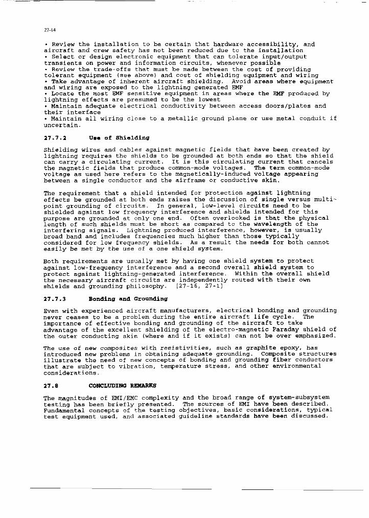
- Review the installation to be certain that hardware accessibility, and aircraft and crew safety has not been reduced due to the installation . Select or design electronic equipment that cari tolerate input/output transients on power and information circuits, whenever possible - Review the trade-offs that must be made between the cost of providing tolerant equipment (sec above) and cost of shielding equipment and wiring . Take advantage of inherent eircraft shielding. Avoid area* where equipment and wiring are exposed to the lightning generated EMF . Locate the most ENF sensitive equipment in areas where the EMF produced by lightning effects are presumed to be the lowest . Maintain adequate electrical conductivity between access doors/plates and their interface . Maintain a11 wiring close to a metallic ground plane or use metal conduit if uncertain.
17.7.1 IJaa of Shielcling
Shielding "ires and tables against magnetic fields that have been created by lightning requires the shields to be grounded at both ends SO that the shield cari carry a circulating current. It is this circulating current that cancels the magnetic fields that produce conunon-mode voltages. The term common-mode voltage as used here refers to the magnetically-induced voltage appearing between a single conductor and the airframe or conductive skin.
The requirement that a shield intended for protection against lightning effects be grounded at both ends raises the discussion of single versus multi- point grounding of circuits. In general, low-level circuits need to be shielded against 10" frequency interference and shields intended for this purpose are grounded at only one end. Often overlooked is that the physical length of such shields must be short as compared to the wavelength of the interfering signal*. Lightning produced interference, however, is usually broad band and includes frequencies much higher than those typically considered for 10" frequency shields. As a result the needs for both cannot easily be met by the use of a one shield system.
Both requirements are usually met by having one shield system to protect against low-frequency interference and a second overall shield system to protect against lightning-generated interference. Within the overall shield the necessary aircraft circuits are independently routed with their own shields and grounding philosophy. 127-16, 27-11
27.1.3 Bonding and Grounding
Even with experienced aircraft manufacturers, electrical bonding and grounding never cesses to be a problem during the entire aircraft life cycle. The importance of effective bonding and grounding of the aircraft to take advantage of the excellent shielding of the electro-magnetic Faraday shield of the outer conducting skin (where and if it exists) cari not be over emphasized.
The use of new composites with resistivities, such as graphite epoxy, has introduced new problems in obtaining adequate grounding. Composite structures illustrate the need of new concepts of bonding and grounding fiber conductors that are subject to vibration, temperature stress, and other environmental considerations.
27.8 coNcLUDINQ R-s
The magnitudes of EMI/EMC complexity and the broad range of system-subsystem testing has been briefly presented. The sources of EM1 have been described. Fundamental concept* of the testing objectives, basic considerations, typical test equipment used, and associated guideline standards bave been discussed.

27-1s
REFERENCES
27-l. RTCA/DO-laOC, "Environmental Conditions and Test Procedures For Airborne Equipment", Radio Technical Commission for Aeronautics, Suite 500; 1425 K ~treet, N.w., Washington, D.C. 20005, 4 December 1989.
27-2. Keiser, B., D.Sc.E.E., "Principles of Electromagnetic Compatibility", Published in the USA by ARTECH HOUSE, Ix., 610 Washington Street, Dedham, Massachusetts, copyright 1979.
27-3. ANSI C95.1-1982, "American National Standard Safety Levels With Respect to Human Exposure to Radio Frequency Electrornagnetic Fields, 300 KiloHertz to 100 GigaHertz'.
27-4. Newton, P.M., 'Aircraft Testing in the Electromagnetic Environment', paper 28, AGARD Conference Proceedings No. 470, Flight in Adverse Environmental Conditions.
27-5. MIL-STD-462, "Electromagnetic Interference Characteristics, Measurement Of", U.S. Department of Defense.
27-6. MIL-STD-461C, "Electromagnetic Emission and Susceptibility Interference Requirements for the Control of Electromagnetic Interferences", U.S. Department of Defense, 4 August 1986.
27-7. MIL-STD-449, "Radio Frequency Spectrum Characteristics, Measurement of", U.S. Department of Defense.
27-8. MIL-STD-704, 'Electric Power Aircraft, Characteristics and Utilization Of", U.S. Department of Defense.
27-9. NACSBM 5100, "Radiation Standard for Communication and Other Information Processing Equipment", U.S. Department of Defense.
27-10. MIL-E-6051, "Electromagnetic Compatibility Requirements, Systems", U.S. Department of Defense.
27-11. Fisher, F.A., and Plumer, J.A., "Lightning Protection of Aircraft". Published in USA. NASA Reference Publication 1008, October 1977.
27-12. AIR 1406, l Lightning Protection and Static Electrification", Society of Automotive Engineers, February 1976.
27-13. "The SEU Concept., Military & Aerospace Electronics', PennWell Publishing CO., August 1992. 27-14. MIL-HDBK-217, "Reliability Prediction of Electronic Equipment", U.S. Department of Defense, 1991.
27-15. White, D.R.J., "A Handbook Series on Electromagnetic Interference and Compatibility", First Edition, published in USA by Don White Consultants, IllC., Germantown, Maryland. 1973-1975, Volumes 1 through IV.
27-16. Borek, Robert W., "Practical Aspects of Instrumentation System Installation', AGARDograph No. 160 Vol. 13, Flight Test Instrumentation series.
BIBLIOQRAPHY
-__ _
MIL-HDBK-35 (USAF), "Management and Design Guidance Electromagnetic Radiation Hardness for Air Launched Ordnance Systems", U.S. Department of Defense, 15 January 1981.
MIL-STD-463, "Definitions and Systems of Units, Electromagnetic Interference Technology", U.S. Department of Defense.
MIL-STD-220, "Methods of Insertion Loss Measurements, Filters", U.S. Department of Defense.
MIL-STD-285, "Measurements for Enclos~~es, Electromagnetic Shielding, for Electronic Test Purposes, Methods of", U.S. Department of Defense.
MIL-STD-1757A. "Lightning Qualification Test Techniques for Aerospace Vehicles and Hardware', U.S. Department of Defense.
DoD-HDBK-263, "Electrostatic Discharge Control Handbook for Protection of Electrical and Electronic Parts, Assemblies, and Equipment (Excluding Electrically Initiated Explosives)", May 1980.
FCC Rules Part 15, "Low-Leva1 RF Devices", and Part 18, "Industrial, Scientific, and Medical Equipment.
AFSC DH 1-4, "Air Force EMC Design Handbook", 10 January 1972.
FAA-AC-020-0136, 'Protection of Aircraft Electricsl/Electronic Systems Against the Indirect Effects of Lightning", Advisory Circular, Federal Aviation Agency, U.S. Department of Transportation, 5 March 1990.
Redman, M.B., "Electromagnetic Compatibility and the Flight Test Engineer", Proceedings of the 18th Annual Symposium of the Society of Flight Test Engineers, Amsterdam, 28 September - 2 October 1987.