Electrostatic Precipitation System for Radionuclide ... · Wide range of in- house fabrication...
18
R E S E A R C H & D E V E L O P M E N T Copyright © 2017 Creare LLC An unpublished work. All rights reserved. MTG-17-11-6351/1018113-1 Electrostatic Precipitation System for Radionuclide Particle Collection DNN R&D SBIR Review December 5, 2017 Ariane Chepko ([email protected]) Michael Swanwick Patrick Magari
Transcript of Electrostatic Precipitation System for Radionuclide ... · Wide range of in- house fabrication...

Click to edit Master title style
Click to edit Master subtitle style
MTG-12-XX-XXXX / XXXX - 1
R E S E A R C H & D E V E L O P M E N T
Copyright © 2017 Creare LLC An unpublished work. All rights reserved. MTG-17-11-6351/1018113-1
Electrostatic Precipitation System for Radionuclide Particle Collection
DNN R&D SBIR Review
December 5, 2017
Ariane Chepko ([email protected]) Michael Swanwick
Patrick Magari

MTG-17-11-6351/1018113-2
Copyright © 2017 Creare LLC
An unpublished work. All rights reserved.
SBIR/STTR Rights Notice (JAN 2015)
These SBIR/STTR data are furnished with SBIR/STTR rights under Award No. DE-SC0015731. Unless the Government obtains permission from the Recipient otherwise, the Government will protect SBIR/STTR data from non-governmental use and from disclosure outside the Government, except for purposes of review, for a period starting at the receipt of the SBIR/STTR data and ending after 4 years, unless extended in accordance with 48 CFR 27.409(h), from the delivery of the last technical deliverable under this award. In order for SBIR/STTR data to be extended by an SBIR/STTR Phase III award, the Recipient must properly notify DOE’s Office of Scientific and Technical Information (OSTI) before the end of the previous protection period. After the protection period, the Government has a paid-up license to use, and to authorize others to use on its behalf, these data for Government purposes, but is relieved of all disclosure prohibitions and assumes no liability for unauthorized use of these data by third parties. This notice shall be affixed to any reproductions of these data, in whole or in part.
DISCLAIMER
This report was prepared by Creare LLC for the Department of Energy. Neither Creare, nor any person acting on its behalf, makes any warranty or representation, express or implied, or assumes any legal liability or responsibility for the accuracy, completeness, or usefulness of the information, apparatus, method or process disclosed in this report. Nor is any representation made that the use of the information, apparatus, method or process disclosed in this report may not infringe privately-owned rights. Creare assumes no liability with respect to the use of, or for damages resulting from the use of, any information, apparatus, method or process disclosed in this report.
Acknowledgment
This material is based upon work supported by the U.S. Department of Energy, Office of Science, under Award Number DE-SC0015731.
Disclaimer
This report was prepared as an account of work sponsored by an agency of the United States Government. Neither the United States Government nor any agency thereof, nor any of their employees, makes any warranty, express or implied, or assumes any legal liability or responsibility for the accuracy, completeness, or usefulness of any information, apparatus, product, or process disclosed, or represents that its use would not infringe privately owned rights. Reference herein to any specific commercial product, process, or service by trade name, trademark, manufacturer, or otherwise does not necessarily constitute or imply its endorsement, recommendation, or favoring by the United States Government or any agency thereof. The views and opinions of authors expressed herein do not necessarily state or reflect those of the United States Government or any agency thereof."

MTG-17-11-6351/1018113-3
Copyright © 2017 Creare LLC
An unpublished work. All rights reserved.
Creare • R&D Engineering Services
– Diverse technical expertise – Over 70 engineers including mechanical, electrical,
materials, aerospace, and software – Highly skilled technicians, machinists, and designers – Industrial and Federal Clients
• Core Competencies – Thermal & Fluid Engineering – Technology Innovation – Cryogenics and Power Systems – Innovative Fabrication and Manufacturing
• Our Facilities – 80,000 Sq. Ft. Laboratory, Shop, and Office Space – Capabilities range from micromachining to running large
outdoor experiments – Wide range of in-house fabrication facilities include
precision machining, laser welding, vacuum brazing, EDM, and thin-film deposition
– Electronics Lab, Clean Room, Environmental Chambers, Inspection Lab, Thermal Vacuum Systems
• Established Record of Technology Transition – Hubble Space Telescope Cryocooler – Mars Curiosity Rover Miniature Vacuum Pumps – Catapult Gap Instrument for Aircraft Carriers – Multiple Spin-off Companies and Technology Licenses

MTG-17-11-6351/1018113-4
Copyright © 2017 Creare LLC
An unpublished work. All rights reserved.
• International Monitoring System Radionuclide Stations – Each station includes Radionuclide Particulate Monitoring – Existing system is the Radionuclide Aerosol Sampler/Analyzer (RASA) – Samples captured in a filter-paper collector over 24-hour sample period (batch process) – Decay of fission isotopes are measured with gamma-ray spectrometry: provides positive
proof of nuclear detonation – Samples are archived for physical analysis if desired
Radionuclide Aerosol Collection
Radionuclide Monitoring Station Locations- 63/80 certified. https://www.ctbto.org/map/
• Challenges for Current Systems – Power Consumption During Fukushima incident, power stability was
an issue for aerosol detection near the site Filter-paper based approach requires high
blower power due to large ΔP across filter
– Sensitivity Blower power limits air flow rate and total
sample quantity Collecting more particles per sample period will
increase instrument sensitivity Environments with high background radiation
can limit instrument sensitivity (higher noise levels require more signal to overcome)
MTG-17-11-6351/1018113-5
Copyright © 2017 Creare LLC
An unpublished work. All rights reserved.
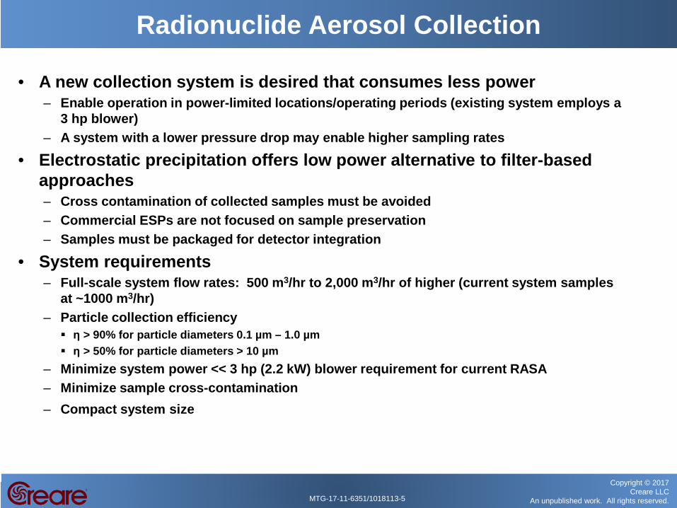
• A new collection system is desired that consumes less power – Enable operation in power-limited locations/operating periods (existing system employs a
3 hp blower) – A system with a lower pressure drop may enable higher sampling rates
• Electrostatic precipitation offers low power alternative to filter-based approaches – Cross contamination of collected samples must be avoided – Commercial ESPs are not focused on sample preservation – Samples must be packaged for detector integration
• System requirements – Full-scale system flow rates: 500 m3/hr to 2,000 m3/hr of higher (current system samples
at ~1000 m3/hr) – Particle collection efficiency η > 90% for particle diameters 0.1 µm – 1.0 µm η > 50% for particle diameters > 10 µm
– Minimize system power << 3 hp (2.2 kW) blower requirement for current RASA – Minimize sample cross-contamination – Compact system size
Radionuclide Aerosol Collection

MTG-17-11-6351/1018113-6
Copyright © 2017 Creare LLC
An unpublished work. All rights reserved.
• Electrostatic precipitation operation: – A high voltage is applied between two electrodes (such as a thin wire and a flat plate) and the
aerosol flow is passed between them – A corona is generated at the discharge electrode – The ionized gas molecules collide with the particles entrained in the flow, and charge builds up
on the particles – The charged particles are drawn to the collector electrode by the electric field force where they
stick, held by static and van der Walls forces
• ESP systems can achieve very high collection efficiencies (>99.5%) across a wide range of particle sizes: 30 nm to >100 µm
Electrostatic Precipitation

MTG-17-11-6351/1018113-7
Copyright © 2017 Creare LLC
An unpublished work. All rights reserved.
• ESP collector design: – ESP form factor challenge—long and narrow
Longer flow-dimension increases collection efficiency
– Goal to minimize system volume (length) while maintaining performance
– Minimize system complexity for sample handling to support long-term, autonomous operation
– Minimize cross-contamination between successive samples
– Mode of Operation: Sample 24 hrs, Decay 24 hrs, Detect 24 hrs
Phase I Design Concept
• Full-scale system requirements: – Fit within general RASA dimensions if possible ~(40 cm x 60 cm x 13 cm) – Maintain particle collection efficiency >90% – Minimize power – Reduce sample to at least 10 cm x 40 cm strip to interface with detector

MTG-17-11-6351/1018113-8
Copyright © 2017 Creare LLC
An unpublished work. All rights reserved.
Flow Inlet Duct
Supply Rolls of Collector Film
Folded Sample Drive Roller/Detector Interface
Blower
Sample Folding Guides
Heat-Sealing Rollers
ESP Flow Channels
• Wire-plate ESP design with multiple rectangular flow channels • Layers of flexible, conductive collector sheets drawn through ESP crosswise
to flow direction • Layers are heat sealed at top and bottom edges • Sample is folded in accordion-like fashion to reduce dimensions to detector
interface (10 cm Height)
Phase I Design Concept

MTG-17-11-6351/1018113-9
Copyright © 2017 Creare LLC
An unpublished work. All rights reserved.
Phase I Design Model Model Geometry
Model Parameters MODEL INPUTS MODEL OUTPUTS
Number of Flow Channels Particle Collection Efficiency Channel Length (L) ESP Power Channel Width (2s) Turn-On Voltage Channel Height (h) Pressure Drop Discharge Wire Pitch (2c) Blower Power
Discharge Wire Radius (rs)
Applied Voltage
Total Flow Rate
Particle Diameter/Properties
• Developed ESP design model for performance prediction and system sizing
• Explored sensitivity of key configuration parameters: – Discharge wire electrode spacing – Channel width – Discharge wire radius – Channel length
• Explored sensitivity of predicted ESP performance to applied voltage and air flow rate
• Compared model to subscale test results and used to generate full-scale design
MTG-17-11-6351/1018113-10
Copyright © 2017 Creare LLC
An unpublished work. All rights reserved.
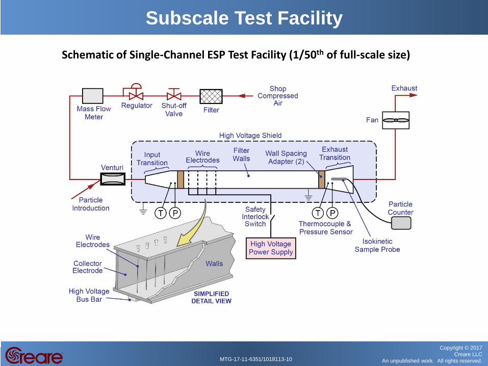
Subscale Test Facility
Schematic of Single-Channel ESP Test Facility (1/50th of full-scale size)
MTG-17-11-6351/1018113-11
Copyright © 2017 Creare LLC
An unpublished work. All rights reserved.
Task 3: Perform Subscale Tests Exhaust Duct
Particle Counter Sample Port
Air Intake
ESP Channel
Particle Collection Bands
Phase I Subscale Tests – Test Facility
Collector Electrode
MTG-17-11-6351/1018113-12
Copyright © 2017 Creare LLC
An unpublished work. All rights reserved.
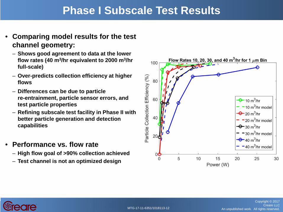
• Comparing model results for the test channel geometry: – Shows good agreement to data at the lower
flow rates (40 m3/hr equivalent to 2000 m3/hr full-scale)
– Over-predicts collection efficiency at higher flows
– Differences can be due to particle re-entrainment, particle sensor errors, and test particle properties
– Refining subscale test facility in Phase II with better particle generation and detection capabilities
• Performance vs. flow rate
– High flow goal of >90% collection achieved – Test channel is not an optimized design
Phase I Subscale Test Results
MTG-17-11-6351/1018113-13
Copyright © 2017 Creare LLC
An unpublished work. All rights reserved.
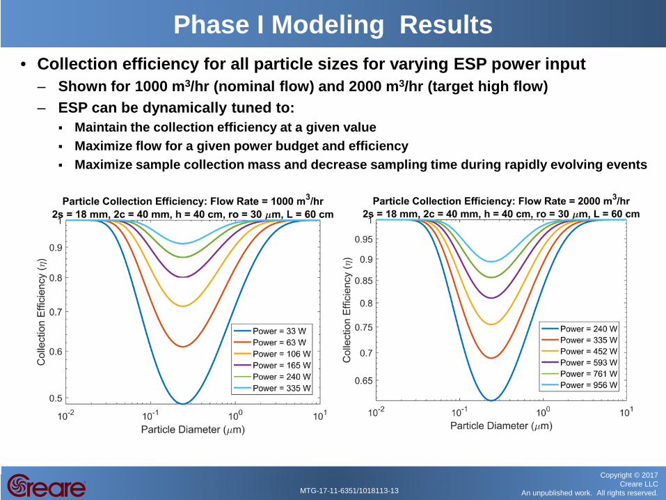
Phase I Modeling Results • Collection efficiency for all particle sizes for varying ESP power input
– Shown for 1000 m3/hr (nominal flow) and 2000 m3/hr (target high flow) – ESP can be dynamically tuned to:
Maintain the collection efficiency at a given value Maximize flow for a given power budget and efficiency Maximize sample collection mass and decrease sampling time during rapidly evolving events

MTG-17-11-6351/1018113-14
Copyright © 2017 Creare LLC
An unpublished work. All rights reserved.
• Blower power – Primary reason for power savings with an ESP over conventional filter – Open channels have very small pressure drop – Ducting to and from ESP will be main contributor to overall pressure drop Included additional 0.15 kPa (0.6 inches H2O) to ESP dP to account for ducting losses in estimating
blower power 2000 m3/hr through 50 ft of 10 inch-diameter ducting with two 90° bends
– Target high flow rate of 2000 m3/hr needs ~260 W blower power (includes 60% blower efficiency)
– Nominal operating point of 1000 m3/hr requires ~90 W (compared to 1-2 kW of RASA blower)
Phase I Modeling Results
40 50 60 70 80 90
Length (cm)
0
100
200
300
400
Blo
wer
Pow
er (W
)
ESP Blower Power for Varying Flow Rates
500 m 3 /hr
1000 m 3 /hr
1500 m 3 /hr
2000 m 3 /hr
40 50 60 70 80 90
Length (cm)
0
0.05
0.1
0.15
0.2
Blo
wer
dP
(kP
a)
ESP Pressure Drop for Varying Flow Rates
500 m 3 /hr
1000 m 3 /hr
1500 m 3 /hr
2000 m 3 /hr

MTG-17-11-6351/1018113-15
Copyright © 2017 Creare LLC
An unpublished work. All rights reserved.
Phase I Modeling Results • Instrument sensitivity is a function of collection efficiency AND flow
rate (sample volume) • Optimization of sensitivity vs. power is better if collection efficiency
target is reduced (90% is goal, IMS requirement is 80%): – At 90% and 2000 m3/hr need 1000 W: gain in sample mass is 3.2x – At 80% and 2000 m3/hr need 590 W: gain in sample mass is 2.9x 41% less power
Using 15,000 m3 as nominal sample volume
0.3 0.4 0.5 0.6 0.7 0.8 0.9 1
Collection Efficiency
0x
1x
2x
3x
4x
5x
6x
Incr
ease
in C
olle
cted
Sam
ple
Mas
s (-
-)
Increase in Sample Mass as a Function
of Flow and Collection Efficiency
500 m 3 /hr
1000 m 3 /hr
1500 m 3 /hr
2000 m 3 /hr
3000 m 3 /hr
0 500 1000 1500 2000
Power (W)
0
20
40
60
80
100
Par
ticle
Col
lect
ion
Effi
cien
cy (%
)
Full-Scale ESP Performance for Varying Flow Rates
(at 0.25 m Particle Diameter)
500 m 3 /hr
1000 m 3 /hr
1500 m 3 /hr
2000 m 3 /hr

MTG-17-11-6351/1018113-16
Copyright © 2017 Creare LLC
An unpublished work. All rights reserved.
• Key results of Phase I: – Developed ESP design model, validated against experiments – Demonstrated ESP operation with flexible collector material – Developed full-scale MESP design that meets all requirements for
radionuclide collection >90% particle collection efficiency for flows up to 2000 m3/hr Total system volume 81 cm x 84 cm x 38 cm Sample folding concept to produce sample size reduction to 10 cm x 40 cm
– Significant power savings over current RASA system ~440 W at nominal flows (1000 m3/hr), 1.4 kW at high-flow target (2000 m3/hr) Up to 5x power reduction from 2.2 kW RASA
– Improvement in instrument sensitivity with higher flow rates – Relaxation of the 90% collection efficiency will result in even larger
reductions in power, while still improving instrument sensitivity – Demonstrated feasibility of multi-layer sample folding and sample
compaction
Phase I Conclusions

MTG-17-11-6351/1018113-17
Copyright © 2017 Creare LLC
An unpublished work. All rights reserved.
• Technical challenges and tasks: – Advanced subscale testing
– Facility improvements with particle generator and detection and inlet and outlet of ESP volume – Explore ESP improvements and power optimization in charging region – Test performance across range of operating conditions (particle resistivity, humidity, etc.) – Determine collected particle layer thickness limitations (will impact system sizing) – Long-term efficiency testing and materials verification
– Develop sample handling system – System to hold collector sheets in ESP volume during sampling, remove, seal, and fold/compress to size necessary for detector integration – Maximize instrument sensitivity – Maximize reliability – Include concept of operations (“re-threading” collector sheets, sample storage, material costs, etc.)
– Design, build, and test full-scale prototype – Measure performance of particle collection and power consumption for varying flow rates/test particles/and atmospheric sampling – Design to accommodate future integration with a detector – Control scheme for system monitoring, high-voltage safety interlocks, and eventual remote operation
Phase II Plans
MTG-17-11-6351/1018113-18
Copyright © 2017 Creare LLC
An unpublished work. All rights reserved.
Questions?