Electronics - Department of Education Tasmanian Qualifications Authority Page 3 of 21 Criterion 4:...
21
Electronics Course Code: ELT315114 External Assessment Specifications 2014 - 2018 Tasmanian Qualifications Authority Page 1 of 21 PURPOSE The purpose of the External Assessment Specifications is to provide information about the external assessment that defines: the external assessable aspects of the criterion standards of ELT315114 Electronics the externally assessed course areas the nature and range of appropriate types of items 1 , and the structure of the external assessment. These definitions are to be in sufficient detail that they will serve both as a blueprint, describing all the elements required to develop the assessment, and as a basis for accountability. The External Assessment Specifications are primarily written for use by the setters of the assessment. Whenever a new external assessment is required, the assessment is to comply with these technical specifications. Assessments may differ from year to year within the framework and rules provided by these specifications. INTRODUCTION The external assessment for ELT315114 Electronics consists of a written examination. The external assessment is designed to assess the standard of achievement of skills, knowledge and understanding of candidates in targeted course areas. Understanding is assessed by the degree to which both knowledge of electronics circuits and their components, design, and also testing and prototyping techniques, are applied to a range of external assessment item types 2 . The course document ELT315114 Electronics is the document used for the development of the examination. 1 In these specifications, the term item is defined as an individual task to be undertaken by candidates. The task may be divided into several parts. 2 Definitions of relevant assessment item types are given in Attachment 1.
Transcript of Electronics - Department of Education Tasmanian Qualifications Authority Page 3 of 21 Criterion 4:...

Electronics
Course Code: ELT315114
External Assessment Specifications 2014 - 2018
Tasmanian Qualifications Authority Page 1 of 21
PURPOSE
The purpose of the External Assessment Specifications is to provide information about the external assessment that defines:
the external assessable aspects of the criterion standards of ELT315114 Electronics
the externally assessed course areas
the nature and range of appropriate types of items1, and
the structure of the external assessment.
These definitions are to be in sufficient detail that they will serve both as a blueprint, describing all the elements required to develop the assessment, and as a basis for accountability.
The External Assessment Specifications are primarily written for use by the setters of the assessment.
Whenever a new external assessment is required, the assessment is to comply with these technical specifications. Assessments may differ from year to year within the framework and rules provided by these specifications.
INTRODUCTION
The external assessment for ELT315114 Electronics consists of a written examination. The external assessment is designed to assess the standard of achievement of skills, knowledge and understanding of candidates in targeted course areas. Understanding is assessed by the degree to which both knowledge of electronics circuits and their components, design, and also testing and prototyping techniques, are applied to a range of external assessment item types2.
The course document ELT315114 Electronics is the document used for the development of the examination.
1 In these specifications, the term item is defined as an individual task to be undertaken by candidates. The task may be divided into several parts.
2 Definitions of relevant assessment item types are given in Attachment 1.

Electronics
Tasmanian Qualifications Authority Page 2 of 21
OVERALL CONDITIONS
The time/date of the examination are set annually by the Office of TASC
The examination has a duration of three (3) hours
An additional fifteen (15) minutes reading time is given
The TASC External Assessment Rule applies to this external assessment. Details of the rule are published on the TASC website https://www.tasc.tas.gov.au/students/exams/rules/
TASC appoints appropriate persons to set and mark assessments.
SPECIFIC MATERIALS AND EQUIPMENT APPROVED FOR USE BY CANDIDATES
A calculator as approved by TASC (Refer to https://www.tasc.tas.gov.au/students/exams/what-can-i-take-to-my-exam/)
Current External Examination Information Sheet for ELT315114 Electronics.
ASSESSMENT
The following aspects of four (4) of the criteria and their standards described in the course document are externally assessed. These define the expectations for the nature, scope and level of demand of the targeted course areas.
Criterion 1: Apply knowledge and skills in designing, testing, building, and experimenting with circuits
Aspects of Criterion 1 standards are examinable3 include:
o identifies appropriate equipment and technologies to design, measure, test and build circuits in a given context
o identifies hazards, and determines health and safety procedures, including specification of appropriate personal protective equipment (PPE)
o anticipates and identifies faults, and devises and evaluates tests or procedures to locate and correct them
o uses, devises and expands upon a systematic approach to solving design problems (e.g. block diagrams)
3 Examinable means the aspects of criteria standards assessable through external assessment.

Electronics
Tasmanian Qualifications Authority Page 3 of 21
Criterion 4: Apply knowledge and understanding of digital and analogue circuits and their components
All aspects of Criterion 4 standards are examinable except those that require mathematic calculations. No calculations will be required when predicting the outcome of changes made to circuits studied. No conversion from one number system to another will be required.
The application of information to a ‘broad range’ of principles studied is assessed through a sample of principles from a possible range.
Criterion 5: Apply knowledge of digital and analogue systems in describing the function and operation of components and circuits
All aspects of Criterion 5 standards are examinable.
Criterion 7: Apply knowledge and understanding of mathematical concepts in electronics
All aspects of Criterion 7 standards are examinable.
The examination must include items that separately and together give opportunities to demonstrate the standards from rating C to rating A.
Final results will be awarded as a rating of A, B, C, t or z in the above criteria. These ratings are used in determining the final award according to the algorithm in the course document.
EXAMINATION CONTENT
A representative sample4, encompassing a large proportion of the targeted course areas, is used to test the standard of skills, knowledge and understanding of a candidate
The relative weighting5 of items within a Section is indicated by:
o the relative allocation of marks, and
o space6 for responses
4 Representative sample: a subset of the target course areas that accurately reflects the total target course area.
5 Relative weighting: the relative emphasis on the assessment of an item compared with other items within a group,that will influence the final result, that is, the rating.
6 Space: a number of lines provided in the item-and-response booklets indicative of the expected extent of responses.

Electronics
Tasmanian Qualifications Authority Page 4 of 21
Where the candidate is required to perform a calculation the answer should be given to three significant figures unless otherwise indicated
A candidate may be asked to show by calculation that a particular component or attribute of a circuit has a given numerical value. Where this particular value is needed in a later item about the same circuit, candidates will be told the value that should be assumed in working out their response to this later item.
General guidelines for writing items
Items are written:
using language/course-specific terminology as outlined in the course document
using unambiguous plain English.
Electronics
Tasmanian Qualifications Authority Page 5 of 21
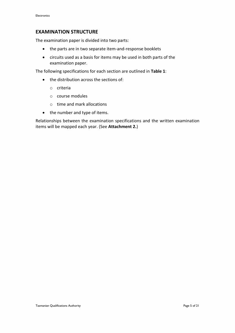
EXAMINATION STRUCTURE
The examination paper is divided into two parts:
the parts are in two separate item-and-response booklets
circuits used as a basis for items may be used in both parts of the examination paper.
The following specifications for each section are outlined in Table 1:
the distribution across the sections of:
o criteria
o course modules
o time and mark allocations
the number and type of items.
Relationships between the examination specifications and the written examination items will be mapped each year. (See Attachment 2.)

Electronics
Tasmanian Qualifications Authority Page 6 of 21
Table 1: ELT315114 Electronics 2014 Written Examination Structure
Section Part 1 Part 2
Criteria (See details in the Assessment section)
Criteria 1, 4
Criteria 5 and 7
Course Area
Core Skills and Knowledge
Modules 1 – 5
Core Skills and Knowledge
Modules 1 - 5
Number of items
10 – 15 items, broken into parts 10 – 15 items, broken into parts
Compulsory items
All All
Item type(s)
(See Attachment 1 for definitions and exemplars)
Context of items
A balance of routine and non-routine contexts
For each criteria, a balance of 40% (by mark value) recall style items and 60% analysis and problem solving style items
Response format
A balance of items ranging from short to extended formats
Assessment of response
Mostly closed-ended responses and some open-ended responses.
Suggested time allocation
90 minutes 90 minutes
Mark allocation
I mark per minute:
Criterion 1 – 45 marks
Criterion 4 – 45 marks
Total = 90 marks
I mark per minute:
Criterion 5 – 45 marks
Criterion 7 – 45 marks
Total = 90 marks

Electronics
Tasmanian Qualifications Authority Page 7 of 21
ATTACHMENT 1
Written Examination Item types
In these specifications, the term ‘item’ is defined as an individual task to be undertaken by candidates. The task may be divided into several sub-parts, although if sufficiently distinct these sub-parts may need to be categorized as separate items.
Item types for this examination can be categorised in terms of:
CATEGORY ITEM TYPES AND DEFINTIONS
EXEMPLARS
The context of the item
Routine context
These items are set in familiar contexts and generally require rehearsed skills.
(Reference: Electronics Exam Paper 2013, Section C, Question 13)
You must show your working.
(a) Convert the binary number to:
(i) hexadecimal (1 mark) (ii) decimal (1 mark)
(b) Express in BCD form. (1 mark)
Non-routine context
These items are set in unfamiliar contexts and generally require the combination, and sometimes the selection, of a set of skills.
(Reference: Electronics Exam Paper 2013, Section B, Question 9)
An experimenter is designing a temperature control circuit for an industrial heater.
This comparator below is part of a test circuit. Components R3 and R5 have not yet been placed in the circuit.
1011002
78510

Electronics
Tasmanian Qualifications Authority Page 8 of 21
The characteristics of the thermistor are shown below.
The heater will switch on whenever the temperature falls below 45˚C.
(a) What is the resistance of the thermistor when the temperature is 45˚C? (1 mark)
(b) What should the output voltage ( ) be when the temperature is 40˚C? Explain why.
(1 mark)
Vout
Electronics
Tasmanian Qualifications Authority Page 9 of 21
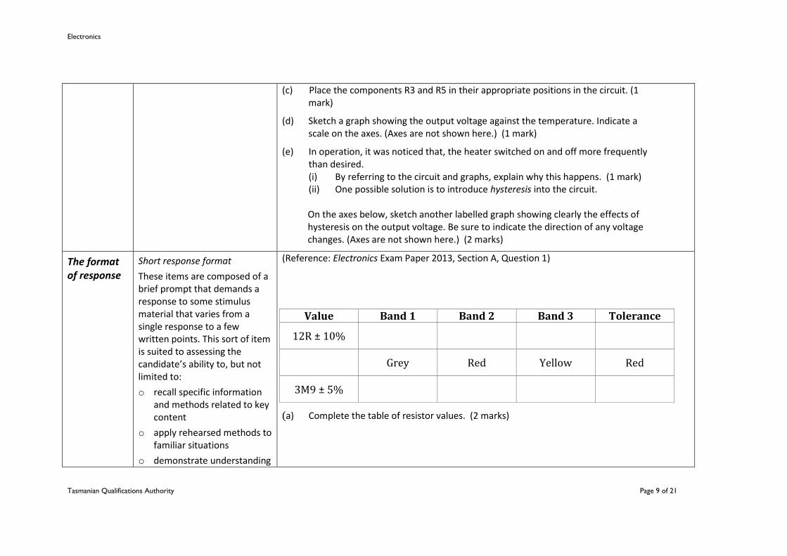
(c) Place the components R3 and R5 in their appropriate positions in the circuit. (1 mark)
(d) Sketch a graph showing the output voltage against the temperature. Indicate a scale on the axes. (Axes are not shown here.) (1 mark)
(e) In operation, it was noticed that, the heater switched on and off more frequently than desired.
(i) By referring to the circuit and graphs, explain why this happens. (1 mark) (ii) One possible solution is to introduce hysteresis into the circuit. On the axes below, sketch another labelled graph showing clearly the effects of
hysteresis on the output voltage. Be sure to indicate the direction of any voltage changes. (Axes are not shown here.) (2 marks)
The format of response
Short response format
These items are composed of a brief prompt that demands a response to some stimulus material that varies from a single response to a few written points. This sort of item is suited to assessing the candidate’s ability to, but not limited to:
o recall specific information and methods related to key content
o apply rehearsed methods to familiar situations
o demonstrate understanding
(Reference: Electronics Exam Paper 2013, Section A, Question 1)
(a) Complete the table of resistor values. (2 marks)
Value Band 1 Band 2 Band 3 Tolerance
12R ± 10%
Grey Red Yellow Red
3M9 ± 5%

Electronics
Tasmanian Qualifications Authority Page 10 of 21
of key concepts in previously unseen stimulus material.
(b) Complete the table of capacitor values. (2 marks) The circuit diagram for a bicycle ‘speedometer’ is shown.
(Source: http://electroschematics.com/451/digital-bike-tachometer)
This digital DIY speedometer for bikes uses two reed switches to get the speed
picofarads (code) nF F
471
15
33

Electronics
Tasmanian Qualifications Authority Page 11 of 21
information of the bicycle. The reed switches are installed near the rim of the wheel where permanent magnets pass by. The permanent magnets are attached to the wheelspokes and activate the reed switches everytime they pass by it. The speed is digitally displayed. The speedometer circuit works according to this principle; the pulses created by the reed contacts are counted within a certain time interval. The resulting count is then displayed and represents the speed of the bike. Two 4026 ICs are used to count the pulses, decode the counter and control two 7-segment LED display. RS flip-flops U3 and U4 function as anti-bounce. The pulses arrive at the counter’s input through gate U7. The measuring period is determined by multivibrator U5/U6 and can be adjusted through potentiometer P1 so that the speedo can be calibrated. The circuit U1/U2 resets the counters.
PIN FUNCTION
1 Clock In
2 Count Enable
3 Display Enable
4 Display Enable Out
5 Carry Out
14 Ungated C-segment
15 Reset
Electronics
Tasmanian Qualifications Authority Page 12 of 21
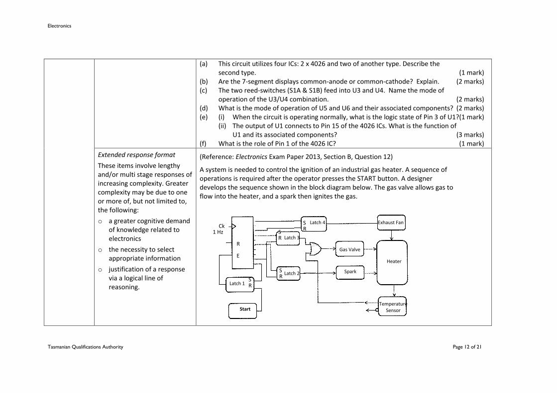
(a) This circuit utilizes four ICs: 2 x 4026 and two of another type. Describe the second type. (1 mark)
(b) Are the 7-segment displays common-anode or common-cathode? Explain. (2 marks) (c) The two reed-switches (S1A & S1B) feed into U3 and U4. Name the mode of
operation of the U3/U4 combination. (2 marks) (d) What is the mode of operation of U5 and U6 and their associated components? (2 marks) (e) (i) When the circuit is operating normally, what is the logic state of Pin 3 of U1?(1 mark) (ii) The output of U1 connects to Pin 15 of the 4026 ICs. What is the function of
U1 and its associated components? (3 marks) (f) What is the role of Pin 1 of the 4026 IC? (1 mark)
Extended response format
These items involve lengthy and/or multi stage responses of increasing complexity. Greater complexity may be due to one or more of, but not limited to, the following:
o a greater cognitive demand of knowledge related to electronics
o the necessity to select appropriate information
o justification of a response via a logical line of reasoning.
(Reference: Electronics Exam Paper 2013, Section B, Question 12)
A system is needed to control the ignition of an industrial gas heater. A sequence of operations is required after the operator presses the START button. A designer develops the sequence shown in the block diagram below. The gas valve allows gas to flow into the heater, and a spark then ignites the gas.
R
Heater
Exhaust Fan
Latch 3
Latch 2
Gas Valve
Spark
Latch 1
E
R S
R
R S
S
R S
Ck 1 Hz
Latch 4
Start Temperature
Sensor
Electronics
Tasmanian Qualifications Authority Page 13 of 21
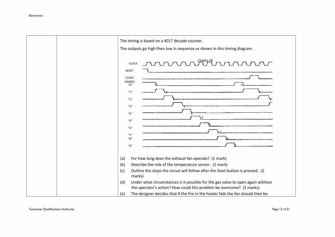
The timing is based on a 4017 decade counter.
The outputs go high then low in sequence as shown in this timing diagram.
(a) For how long does the exhaust fan operate? (1 mark)
(b) Describe the role of the temperature sensor. (1 mark)
(c) Outline the steps the circuit will follow after the Start button is pressed. (2 marks)
(d) Under what circumstances is it possible for the gas valve to open again without the operator’s action? How could this problem be overcome? (2 marks)
(e) The designer decides that if the fire in the heater fails the fan should then be
CLOCK CD4017B
RESET
CLOCK ENABLE
0
1
2
0
1
2
3
4 5
6
7
8
9
“0”
“1”
“2”
“3”
“4”
“5”
“6”
“7” “8”
“9”
Electronics
Tasmanian Qualifications Authority Page 14 of 21
made to operate for 5 seconds to clear any unburnt gas.
By adding any necessary components to the diagram, show how this could be achieved. Explain how your design will work. (3 marks)
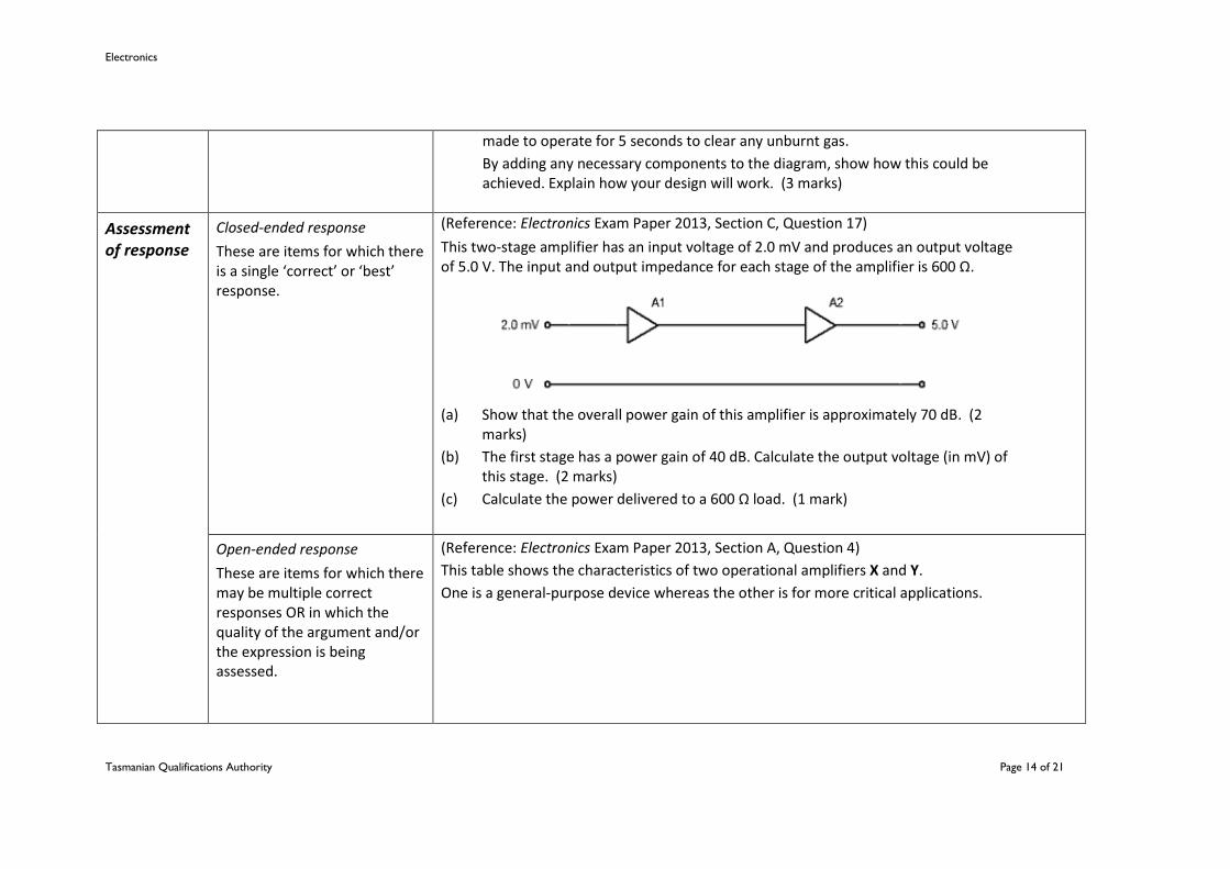
Assessment of response
Closed-ended response
These are items for which there is a single ‘correct’ or ‘best’ response.
(Reference: Electronics Exam Paper 2013, Section C, Question 17)
This two-stage amplifier has an input voltage of 2.0 mV and produces an output voltage of 5.0 V. The input and output impedance for each stage of the amplifier is 600 Ω.
(a) Show that the overall power gain of this amplifier is approximately 70 dB. (2 marks)
(b) The first stage has a power gain of 40 dB. Calculate the output voltage (in mV) of this stage. (2 marks)
(c) Calculate the power delivered to a 600 Ω load. (1 mark)
Open-ended response
These are items for which there may be multiple correct responses OR in which the quality of the argument and/or the expression is being assessed.
(Reference: Electronics Exam Paper 2013, Section A, Question 4)
This table shows the characteristics of two operational amplifiers X and Y.
One is a general-purpose device whereas the other is for more critical applications.

Electronics
Tasmanian Qualifications Authority Page 15 of 21
(a) Which op amp, X or Y, is nearer to being ideal? (2 marks) Give two reasons for your answer. Reason 1: Reason 2:
Characteristic X Y
Input impedance (MΩ) 2 4
Output impedance (Ω) 100 10
Open-loop Gain (Volts/V) 15k 4M
Unity Gain Bandwidth (MHz) 1 14
Max Supply Voltage (V) ± 15 ± 18
Output Voltage Swing (V) ± 12 ± 14
Slew Rate (V/µV) 0.5 4.5

Electronics
Tasmanian Qualifications Authority Page 16 of 21
ATTACHMENT 2
ELT315114 Electronics 2014 Written Examination Mapping
The Setting Examiner designs examination items to adhere to the External Assessment Specifications (see Table 1). During the writing and critiquing of the examination, the Setting Examiner will map the ELT315114 Electronics examination to the course document and external assessment specifications. This may be achieved through the mapping grids given in Tables 2 - 6.
Mapping provides a summary of relationships between examination items and:
item type
relative importance/weighting
content areas
achievement standard, and
the possible ratings of a response to an item.
Mapping is designed primarily to assist the Setting Examiner to:
see at a glance the range of item types, course coverage and achievement standards used in the examination paper, and
check for:
o representative sampling, and
o adherence to the examination structure specifications.
Checklist
The Setting Examiner conducts a final check for adherence of the written examination to the external assessment specifications by completing a checklist. (See Table 7.)
Electronics
Tasmanian Qualifications Authority Page 17 of 21
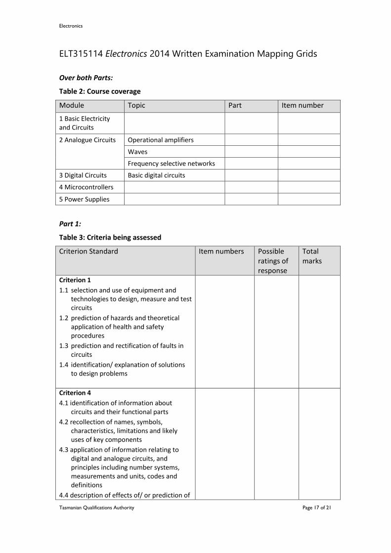
ELT315114 Electronics 2014 Written Examination Mapping Grids
Over both Parts:
Table 2: Course coverage
Module Topic Part Item number
1 Basic Electricity and Circuits
2 Analogue Circuits Operational amplifiers
Waves
Frequency selective networks
3 Digital Circuits Basic digital circuits
4 Microcontrollers
5 Power Supplies
Part 1:
Table 3: Criteria being assessed
Criterion Standard Item numbers
Possible ratings of response
Total marks
Criterion 1
1.1 selection and use of equipment and technologies to design, measure and test circuits
1.2 prediction of hazards and theoretical application of health and safety procedures
1.3 prediction and rectification of faults in circuits
1.4 identification/ explanation of solutions to design problems
Criterion 4
4.1 identification of information about circuits and their functional parts
4.2 recollection of names, symbols, characteristics, limitations and likely uses of key components
4.3 application of information relating to digital and analogue circuits, and principles including number systems, measurements and units, codes and definitions
4.4 description of effects of/ or prediction of
Electronics
Tasmanian Qualifications Authority Page 18 of 21
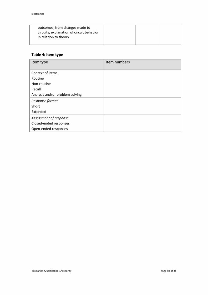
outcomes, from changes made to circuits; explanation of circuit behavior in relation to theory
Table 4: Item type
Item type Item numbers
Context of items
Routine
Non-routine
Recall
Analysis and/or problem solving
Response format
Short
Extended
Assessment of response
Closed-ended responses
Open-ended responses

Electronics
Tasmanian Qualifications Authority Page 19 of 21
Part 2:
Table 5: Criteria being assessed
Criterion Standard Item numbers
Possible ratings of response
Total marks
Criterion 5
5.1 listing/ description of role, function and operation of systems, circuits and components
5.2 description/ prediction of likely input and output signals or conditions of components/ circuits; use of diagrams; identification of possible alternative components or circuits that perform a similar function
5.3 identification of circuit elements from analysis of block diagrams; design of circuits from analysis of block diagrams
Criterion 7
7.1 adaption/ selection of mathematical concepts and techniques to model and predict, and analyse/ evaluate circuits
7.2 calculation of component values or physical quantities using appropriate mathematical formulae, units and evaluation of values
7.3 use/ selection of, and interpretation of graphs and table/ other mathematical tools; communication of information

Electronics
Tasmanian Qualifications Authority Page 20 of 21
Table 6: Item type
Item type Item numbers
Context of items
Routine
Non-routine
Recall
Analysis and/or problem solving
Response format
Short
Extended
Assessment of response
Closed-ended responses
Open-ended responses
Electronics
Tasmanian Qualifications Authority Page 21 of 21
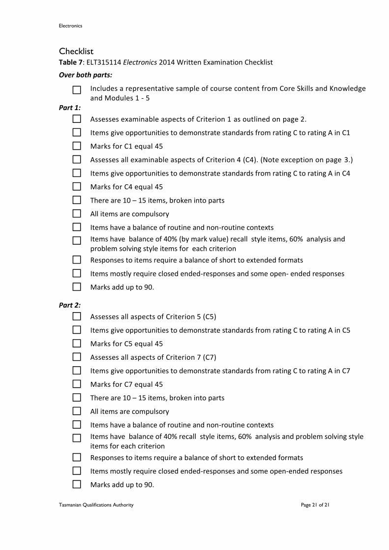
Checklist Table 7: ELT315114 Electronics 2014 Written Examination Checklist
Over both parts:
Includes a representative sample of course content from Core Skills and Knowledge and Modules 1 - 5
Part 1:
Assesses examinable aspects of Criterion 1 as outlined on page 2.
Items give opportunities to demonstrate standards from rating C to rating A in C1
Marks for C1 equal 45
Assesses all examinable aspects of Criterion 4 (C4). (Note exception on page 3.)
Items give opportunities to demonstrate standards from rating C to rating A in C4
Marks for C4 equal 45
There are 10 – 15 items, broken into parts
All items are compulsory
Items have a balance of routine and non-routine contexts
Items have balance of 40% (by mark value) recall style items, 60% analysis and problem solving style items for each criterion
Responses to items require a balance of short to extended formats
Items mostly require closed ended-responses and some open- ended responses
Marks add up to 90.
Part 2:
Assesses all aspects of Criterion 5 (C5)
Items give opportunities to demonstrate standards from rating C to rating A in C5
Marks for C5 equal 45
Assesses all aspects of Criterion 7 (C7)
Items give opportunities to demonstrate standards from rating C to rating A in C7
Marks for C7 equal 45
There are 10 – 15 items, broken into parts
All items are compulsory
Items have a balance of routine and non-routine contexts
Items have balance of 40% recall style items, 60% analysis and problem solving style items for each criterion
Responses to items require a balance of short to extended formats
Items mostly require closed ended-responses and some open-ended responses
Marks add up to 90.