ELECTRONIC LEVELING OPERATION AND SERVICE … · the use of the lippert electronic leveling system...
25
ELECTRONIC LEVELING OPERATION AND SERVICE MANUAL
Transcript of ELECTRONIC LEVELING OPERATION AND SERVICE … · the use of the lippert electronic leveling system...

ELECTRONIC LEVELING OPERATION AND SERVICE MANUAL
TABLE OF CONTENTS
SYSTEM……………………………………………..Warning…………………………………..Description………………………………Fluid Recommendation……………..Preventative Maintenance………..Jacks………………………………………Power Units……………………………..Valve Block Assemblies…………….
CONTROLS………………………………………...Features……………….…………………Wiring Requirements………………..Air and Auxiliary Features.………..Air and Aux Configuration…………Error Mode……..………………………..User Alarm Mode…..………………….Level Zero Point Configuration…..Miscellaneous…..……………………...Control Panel-Automatic…………...
OPERATION………………………………………...Selecting a Site………………………...Automatic Leveling Procedure…...Manual Leveling Procedure……….Jack Retract Procedures…………..Manual Override-Jacks……..……….Manual Override-Power System….Automatic Shut-off…………………….Drive-Away Protection……………….
SERVICE…………………………………………….Troubleshooting……………………….Chart……………………………………….Power Unit……………………………….Plumbing Diagrams…………………..Wiring Diagram................………...Ordering Parts………………………….
WARRANTY………………………………………...Warranty Registration.................
33455678
9999
101011111213
141414151617181919
20202122232425
2627
2
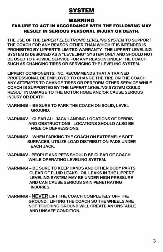
SYSTEM
WARNINGFAILURE TO ACT IN ACCORDANCE WITH THE FOLLOWING MAY
RESULT IN SERIOUS PERSONAL INJURY OR DEATH.
THE USE OF THE LIPPERT ELECTRONIC LEVELING SYSTEM TO SUPPORTTHE COACH FOR ANY REASON OTHER THAN WHICH IT IS INTENDED ISPROHIBITED BY LIPPERT’S LIMITED WARRANTY. THE LIPPERT LEVELINGSYSTEM IS DESIGNED AS A “LEVELING” SYSTEM ONLY AND SHOULD NOTBE USED TO PROVIDE SERVICE FOR ANY REASON UNDER THE COACHSUCH AS CHANGING TIRES OR SERVICING THE LEVELING SYSTEM.
LIPPERT COMPONENTS, INC. RECOMMENDS THAT A TRAINEDPROFESSIONAL BE EMPLOYED TO CHANGE THE TIRE ON THE COACH.ANY ATTEMPTS TO CHANGE TIRES OR PERFORM OTHER SERVICE WHILECOACH IS SUPPORTED BY THE LIPPERT LEVELING SYSTEM COULDRESULT IN DAMAGE TO THE MOTOR HOME AND/OR CAUSE SERIOUSINJURY OR DEATH.
WARNING! – BE SURE TO PARK THE COACH ON SOLID, LEVEL GROUND.
WARNING! – CLEAR ALL JACK LANDING LOCATIONS OF DEBRIS AND OBSTRUCTIONS. LOCATIONS SHOULD ALSO BE FREE OF DEPRESSIONS.
WARNING! – WHEN PARKING THE COACH ON EXTREMELY SOFT SURFACES, UTILIZE LOAD DISTRIBUTION PADS UNDER EACH JACK.
WARNING! - PEOPLE AND PETS SHOULD BE CLEAR OF COACH WHILE OPERATING LEVELING SYSTEM.
WARNING! – BE SURE TO KEEP HANDS AND OTHER BODY PARTS CLEAR OF FLUID LEAKS. OIL LEAKS IN THE LIPPERT LEVELING SYSTEM MAY BE UNDER HIGH PRESSURE AND CAN CAUSE SERIOUS SKIN PENETRATING INJURIES.
WARNING! - NEVER LIFT THE COACH COMPLETELY OFF THE GROUND. LIFTING THE COACH SO THE WHEELS ARE NOT TOUCHING GROUND WILL CREATE AN UNSTABLE AND UNSAFE CONDITION.
3

PRIOR TO OPERATION
The leveling system shall only be operated under the following conditions:1. The coach is parked on a reasonably level surface.2. The coach “PARKING BRAKE” is engaged.3. The coach transmission should be in the neutral or park position4. The ignition is in the run position, or engine is running.5. Be sure all person, pets and property are clear of the coach while
Lippert Leveling System is in operation.
SYSTEM DESCRIPTION
Please read and study the operating manual before you operate the levelingsystem.
The Lippert Electronic Leveling System is an electric/hydraulic system. A 12V DCelectric motor drives a hydraulic pump that moves fluid through a system ofhoses, fittings and jacks to level and stabilize the coach.
The Lippert Electronic Leveling System is totally integrated into the chassis of thecoach at the manufacturer.
There are no serviceable parts within the electric motor. If the motor fails, PumpUnit must be replaced.
Disassembly of the Pump Assembly voids the warranty.
Mechanical portions of the Lippert Electronic Leveling System are replaceable.Contact Lippert Components, Inc. to obtain replacement parts.
FOR REPLACEMENT PARTS, CALL LIPPERT AT: (866) 524-7821.
COMPONENT DESCRIPTION The Lippert Electronic Leveling System consists ofthe following major components:
Lippert jacks are rated at a lifting capacity appropriate for your coach. Each jack hasa 9" diameter (63.5 square inch) shoe on a ball swivel for maximum surface contacton all surfaces. (12” dia. - 113 sq. in. shoe also available).
Each jack is powered from a central 12VDC motor/pump assembly, which alsoincludes the hydraulic oil reservoir tank, control valve manifold, and solenoid valves.
The Lippert Electronic Leveling System is controlled electronically from thedriver’s seat of the coach. The control panel is mounted in the dash. Thesystem can be operated in a manual mode or a fully automatic mode.
4

FLUID RECOMMENDATION
The Lippert Electronic Leveling System is pre-filled, primed and ready to operatedirect from the manufacturer. Type “A” Automatic Transmission Fluid (ATF) is utilizedand will work. ATF with Dexron III or Mercon 5 or a blend of both is recommendedby Lippert Components, Inc.
In colder temperatures (less than 10° F) the jacks may extend and retract slowlydue to the fluid’s molecular nature. For cold weather operation, fluid speciallyformulated for low temperatures may be desirable.
Please consult factory before using any other fluids.
PREVENTATIVE MAINTENANCE PROCEDURES
1. Change fluid in RESERVOIR ONLY every 36 months.a) Check fluid only when jacks are fully retracted.b) Always fill the reservoir with the jacks in the fully retracted position. Filling
reservoir when jacks are extended will cause reservoir to overflow into itscompartment when jacks are retracted.
c) When checking fluid level, fluid should be within ¼” of fill spout lip.
2. Check the fluid level every month.
3. Inspect and clean all Pump Unit electrical connections every 12 months. If corrosion is evident, spray unit with WD-40 or equivalent
4. Remove dirt and road debris from jacks as needed.
WWWWWARNINGARNINGARNINGARNINGARNING:Your coach should be supported at both front and rear axles with
jack stands before working underneath.Failure to do so may result in personal injury or death.
5. If jacks are down for extended periods, it is recommended to spray exposed leveling jack rods with a silicone lubricant every seven days for protection. If your coach is located in a salty environment, it is recommended to spray the rods every 2 to 3 days.
IF YOU HAVE ANY PROBLEMS OR QUESTIONS CONSULT YOUR LOCALAUTHORIZED DEALER OR CALL LIPPERT AT:
(866) 524-7821.
5
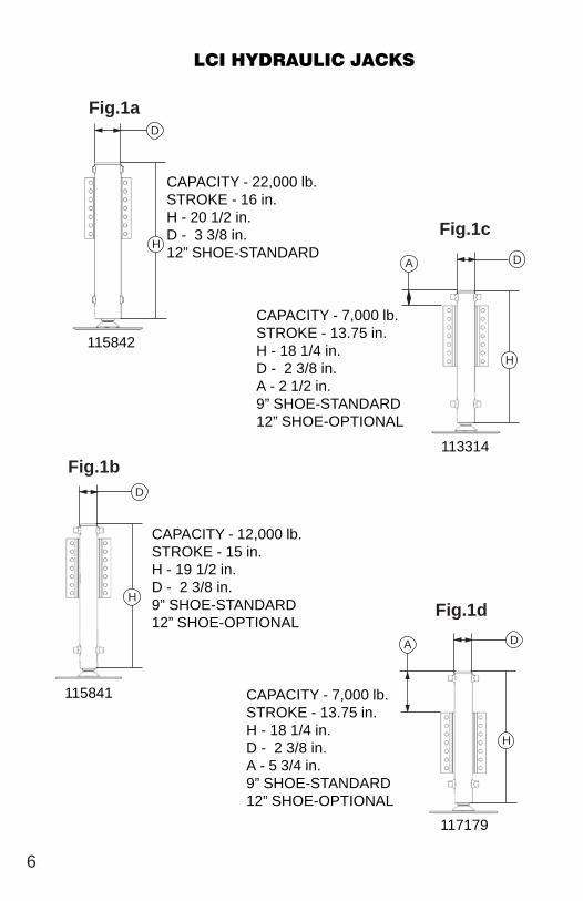
CAPACITY - 22,000 lb.STROKE - 16 in.H - 20 1/2 in.D - 3 3/8 in.12” SHOE-STANDARD
LCI HYDRAULIC JACKS
D
D
DH
H
H
115842
115841
Fig.1a
Fig.1b
Fig.1c
CAPACITY - 12,000 lb.STROKE - 15 in.H - 19 1/2 in.D - 2 3/8 in.9” SHOE-STANDARD12” SHOE-OPTIONAL
CAPACITY - 7,000 lb.STROKE - 13.75 in.H - 18 1/4 in.D - 2 3/8 in.A - 2 1/2 in.9” SHOE-STANDARD12” SHOE-OPTIONAL
CAPACITY - 7,000 lb.STROKE - 13.75 in.H - 18 1/4 in.D - 2 3/8 in.A - 5 3/4 in.9” SHOE-STANDARD12” SHOE-OPTIONAL
D
H
Fig.1d
117179
A
A
6
113314

POWER ASSEMBLY
Fig. 2
7
Ma
nu
al O
verr
ide
12
V B
i-d
ire
ctio
na
l DC
Mo
tor
Pu
mp
Pilo
t Op
era
ted
Ch
eck
Va
lve

VALVE BLOCK ASSEMBLY
8
Hyd
rau
lic V
alv
e M
an
ifold
Va
lve
Co
il
Val
ve
Mo
tor
Re
vers
ing
So
len
oid
Fig. 3a - Leveling with Remote Pump Unit
Pre
ssu
re S
witc
h
Replacement Pressure Switch - Nason with Deutsch Connector
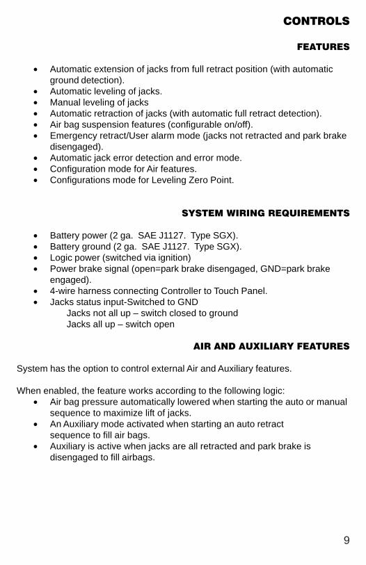
CONTROLS
FEATURES
• Automatic extension of jacks from full retract position (with automaticground detection).
• Automatic leveling of jacks.• Manual leveling of jacks• Automatic retraction of jacks (with automatic full retract detection).• Air bag suspension features (configurable on/off).• Emergency retract/User alarm mode (jacks not retracted and park brake
disengaged).• Automatic jack error detection and error mode.• Configuration mode for Air features.• Configurations mode for Leveling Zero Point.
SYSTEM WIRING REQUIREMENTS
• Battery power (2 ga. SAE J1127. Type SGX).• Battery ground (2 ga. SAE J1127. Type SGX).• Logic power (switched via ignition)• Power brake signal (open=park brake disengaged, GND=park brake
engaged).• 4-wire harness connecting Controller to Touch Panel.• Jacks status input-Switched to GND
Jacks not all up – switch closed to groundJacks all up – switch open
AIR AND AUXILIARY FEATURES
System has the option to control external Air and Auxiliary features.
When enabled, the feature works according to the following logic:• Air bag pressure automatically lowered when starting the auto or manual
sequence to maximize lift of jacks.• An Auxiliary mode activated when starting an auto retract
sequence to fill air bags.• Auxiliary is active when jacks are all retracted and park brake is
disengaged to fill airbags.
9

LEVEL ZERO POINT CALIBRATION
Before auto-leveling features are available, the Level Zero point must be set.This is the point to which the system will return when an auto leveling cycle isinitiated.
To set the zero point (controller module must be fully secured in production intentlocation), first run a manual leveling sequence to get the vehicle to the desiredlevel point. Then activate the Level Zero point configuration mode.
This mode is enabled by performing the following sequence:1. Turn panel off. Then turn panel on.2. Perform the following:
-Press the FRONT switch 5 times.-Press the REAR switch 5 times.
3. At this point all LED outputs will blink, and the buzzer will be off.4. You are now in IDLE mode ready to set Zero Point.5. With a carpenter’s level, manually level the coach. This will give the leveling controls the reference point for the Zero Point Configuration.6. When coach is completely leveled manually press the RETRACT ALL
switch 3 times to set the zero point.
For DIESEL UNITS with Airbag Suspensions ONLY:
NOTE: You may also enter zero mode per above at anytime the system isin IDLE mode. The user then has control to extend any pair of jacks whilein zero mode in order to position the vehicle properly prior toprogramming.
AIR AND AUXILIARY FEATURE CONFIGURATION
For DIESEL UNITS with Airbag Suspensions ONLY:
• Feature is entered ONLY after zero mode programming.• At this point the WAIT LED will blink for 20 seconds. You are now in Air/
Auxiliary Feature Configuration mode.
To enable Air Auxiliary features, perform the following:• Press the RETRACT ALL switch 3 times• User must do this within 20 seconds of entering this mode.
To disable Air features, perform the following:• Do nothing• After 20 seconds, module will exit mode with features disabled.
10

ERROR MODE
If any problem is detected with the jacks, the system will enter error mode. Errormode may be recognized by the blinking of LEFT, LEVEL and RIGHT LEDs.
The following errors are detected by this system:Jack over current/short circuit.Jack under current/ open circuit.Jack extending too long (ground not detected after 2 min.).Jack retracting too long (fully retracted not detected after 2 min.).Out of stroke detection during auto cycle (if enabled).
The user must respond by pressing ON/OFF switch, which resets operation.
All normal features are disabled in Error mode.
If panel loses communication with the controller for more than 5 seconds, thepanel will blink the JACKS DOWN, PARK BRAKE andON/OFF (if included) LEDs.
USER ALARM MODE
If the alarm system detects that the park brake has been disengaged while atleast one jack is not fully retracted and the sensor value changes in any axismore than a predefined amount, the panel will signal this error to the user.
When in alarm mode, all LEDs will flash and the buzzer will beep. The StatusLEDs will show the system status.
The system performs an automatic retract.
No other features are available in this mode.
11

MISCELLANEOUS
• The system will automatically shut down after 4 minutes of no operation.• Auto leveling cycle cannot be started until all jacks are fully retracted.
Make sure jacks are retracted before attempting to auto level (unit willperform full retract automatically if jacks are not down on the request ofan auto cycle).
• System will refuse any operation when a low voltage condition is present.• System will automatically alarm and retract if park brake is disengaged
and jacks are not retracted with any change in sensor readings. In alarmmode, the only available feature is to retract all jacks.
• Please note the Wait LED shows the status of Air/ Auxiliary features.
Please note that the LEDs blink differently when in special controller modes(error, alarm, and configuration). Learning how to recognize these modes isimportant. Excess slope LED blinks whenever the Y axis (vehicle length) is over5o from programmed level point.
12

Fig
. 4
CONTROL PANEL
13
RE
AD
AN
D U
ND
ER
ST
AN
D O
PE
RA
TO
RS
MA
NU
AL
BE
FO
RE
US
ING
DO
NO
T U
SE
JA
CK
S F
OR
TIR
E R
EM
OV
AL
OR
VE
HIC
LE S
ER
VIC
E.
LEF
T
LCI E
LEC
TR
ON
IC L
EV
ELI
NG
EX
CE
SS
AN
GL
E
CA
UT
ION
!
EN
GA
GE
PA
RK
BR
AK
E
LO
W V
OL
TA
GE
JAC
KS
DO
WN
WA
IT
MA
NA
UT
O
RE
AR
AL
LJA
CK
S
RE
TR
AC
T
RIG
HT
FR
ON
T
ON
OF
F
EX
CE
SS
AN
GL
E L
ED
-CO
AC
H M
AY
NO
T B
EA
BL
E T
O B
E L
EV
EL
ED
IN
CU
RR
EN
T L
OC
AT
ION
AN
D M
US
T B
E M
OV
ED
TO
A M
OR
E L
EV
EL
LO
CA
TIO
N.
EN
GA
GE
PA
RK
BR
AK
E L
ED
-FL
AS
HE
SW
HE
N P
AR
K B
RA
KE
IS
DIS
EN
GA
GE
D;
OF
FW
HE
N P
AR
K B
RA
KE
HA
S B
EE
N E
NG
AG
ED
LO
W V
OLT
AG
E L
ED
-IN
DIC
AT
ES
VO
LTA
GE
HA
S D
RO
PP
ED
BE
LO
W S
AF
E O
PE
RA
BL
EL
EV
EL
.
JA
CK
S D
OW
N L
ED
-IN
DIC
AT
ES
JA
CK
S A
RE
IN A
NY
VA
RIO
US
STA
TE
OF
EX
TE
NS
ION
AN
D N
OT
FU
LLY
RE
TR
AC
TE
D.
WA
IT L
ED
-IN
DIC
AT
ES
TO
TH
E O
PE
RA
TO
RT
O P
AU
SE
PR
IOR
TO
OP
ER
AT
ING
TH
ES
YS
TE
M.
RE
SU
ME
OP
ER
AT
ION
WH
EN
TH
E L
ED
GO
ES
OF
F.
LE
FT
BU
TT
ON
-CO
NT
RO
LS
EX
TE
NS
ION
OF
LE
FT
FR
ON
T A
ND
LE
FT
RE
AR
JA
CK
S.
MA
NU
AL
OP
ER
AT
ION
LE
D-
IND
ICA
TE
SC
ON
TR
OL
S C
AN
BE
OP
ER
AT
ED
MA
NU
AL
LY T
O L
EV
EL
CO
AC
H.
MA
NU
AL
OP
ER
AT
ION
BU
TT
ON
- P
LA
CE
SC
ON
TR
OL
PA
NE
L IN
MA
NU
AL
OP
ER
AT
ION
MO
DE
.
AU
TO
MA
TIC
OP
ER
AT
ION
BU
TT
ON
- P
LA
CE
SC
ON
TR
OL
PA
NE
L IN
AU
TO
MA
TIC
MO
DE
.A
UT
OM
AT
IC O
PE
RA
TIO
N L
ED
- IN
DIC
AT
ES
CO
NT
RO
LS
CA
N B
E O
PE
RA
TE
DA
UT
OM
AT
ICA
LLY
TO
LE
VE
L C
OA
CH
.
FR
ON
T B
UT
TO
N-
CO
NT
RO
LS
EX
TE
NT
ION
OF
BO
TH
FR
ON
T J
AC
KS
.
ON
/OF
F B
UT
TO
N-
TU
RN
S L
EV
EL
ING
SY
ST
EM
ON
AN
D O
FF.
CO
AC
H L
EV
EL
LE
D-
IND
ICA
TE
S T
HA
TC
OA
CH
HA
S B
EE
N L
EV
EL
ED
.
RIG
HT
BU
TT
ON
- C
ON
TR
OL
S E
XT
EN
TIO
N O
F R
IGH
T F
RO
NT
AN
D R
IGH
TR
EA
R J
AC
KS
.
RE
TR
AC
T A
LL
JA
CK
S B
UT
TO
N-
RE
TR
AC
TS
AL
L JA
CK
S A
UT
OM
AT
ICA
LLY
.S
EE
PA
GE
16
FO
R R
ET
RA
CT
PR
OC
ED
UR
ES
RE
AR
BU
TT
ON
-CO
NT
RO
LS
EX
TE
NT
ION
AN
DO
F B
OT
H R
EA
R J
AC
KS
.

14
OPERATIONSELECTING A SITEWhen the coach is parked on an excessive slope the leveling requirements mayexceed the jack lift stroke capability. If the coach is parked on an excessive slope,the coach should be moved to a more level surface before the leveling system isdeployed.
AUTOMATIC LEVELING PROCEDURENOTE: REFER TO FIG. 4 FOR QUESTIONS REGARDING LOCATION AND FUNCTIONS OF THE LIPPERT COMPONENTS, INC. ELECTRONIC LEVELING SYSTEM.NOTE: Coach must be running for LCI Electronic Leveling System tooperate.
1. Push ON/OFF button on Control Panel. The system is now operational and the electronic level lights will become active.
2. Check to see that the Control Pad ENGAGE PARK BRAKE light is not flashing.
NOTE: Engage Parking Brake if ENGAGE PARK BRAKE light is flashing.
3. Push the AUTO button to begin the automatic leveling cycle.
WARNING: After starting the automatic leveling cycle it is very important thatyou do not move around in the coach until the unit is level and thegreen LCI logo light illuminates in the center of the touch pad.Failure to remain still during the leveling cycle could have anaffect on the performance of the leveling system.
4. If further adjustments are necessary, simply push and hold the MAN button for approximately 5 seconds until the light under this button is illuminated. Push the appropriate leg button to override the system and level the coach to your liking.
WWWWWARNINGARNINGARNINGARNINGARNING!NEVER LIFT ALL THE WHEELS OFF THE GROUND
TO LEVEL THE COACH!Lifting all wheels of the ground may result
in serious personal injury or death.
5. Push ON/OFF button to de-energize the system.

MANUAL LEVELING PROCEDURESNOTE: When leveling your coach, the coach should be leveled from FRONT TO REAR first (step 2-4). When the coach is level from FRONT TO REAR, then level the coach from LEFT TO RIGHT (step 5).NOTE: Coach must be running for LCI Electronic Leveling System tooperate.1. Push ON/OFF button on control panel. The system is now operational and the ON/OFF light will be lit. If ON/OFF light is not lit, see PRIOR TO OPERATION page 4.
2. Push and hold MAN button for 5 seconds.
3. Push FRONT button until jacks contact the ground.
4. Push REAR button until jacks contact the ground.
5. Push button FRONT or REAR; if bubble is towards front of coach push REAR button; if bubble is towards rear of coach, push FRONT button. Keep button depressed until bubble is centered.
6. Push LEFT or RIGHT button; if bubble is towards left of coach, push RIGHT button; if bubble is towards right of coach push LEFT button. Keep button depressed until bubble is centered in vial.
NOTE: The right and left jacks are used to level the coach side to side. Pushing the LEFT button on the control panel will extend both left jacks. Pushing the RIGHT button on the control panel will extend both right jacks. Jacks always work in pairs, both front jacks together, both right side jacks, etc.
7. Repeat steps 2 through 5 if needed.
8. Turn power off to leveling system by pushing ON/OFF button.
9. Visually inspect all jacks to ensure all shoes are touching ground. Should one of the rear jack shoes not be touching the ground, press the corresponding LEFT or RIGHT rear jack buttons to lower the corresponding jack to the ground.
WWWWWARNINGARNINGARNINGARNINGARNING!NEVER LIFT ALL THE WHEELS OFF THE GROUND TO LEVEL THE COACH!
Lifting all wheels of the ground may result in serious personal injury or death.
15

JACK RETRACT PROCEDURES
1. Energize the system by pushing ON/OFF button on control panel. The ON/OFF light will be lit.
2. Push the RETRACT ALL JACKS button. All the jacks will start to retract and returns to the full retract position. When all jacks return to full retract position the JACKS DOWN light will go out.
NOTE: If you wish to stop the jacks from retracting, turn the system off and back on again by pushing the on/off pad twice. You can then re-level the coach by following steps 1-5 again.
3. When the JACKS DOWN light goes out, push the ON/OFF button on the Control Panel to deenergize the system. After a brief visual inspection around the coach to verify the jacks are fully retracted, you may proceed to travel.
NOTE: When in the MANUAL mode, if the RETRACT button is pushed thejacks will only retract as long as the RETRACT button is depressed. InAUTOMATIC mode, the RETRACT button need only be pressed once andreleased for the jacks to fully retract.
16
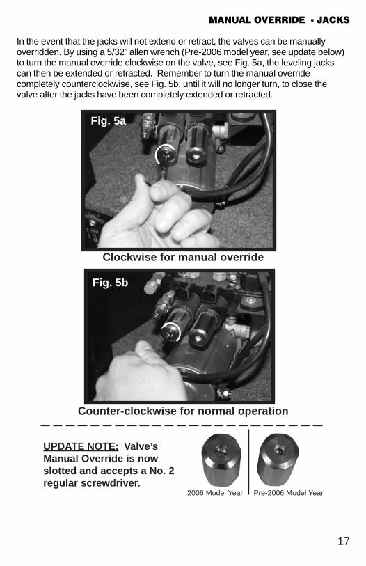
MANUAL OVERRIDE - JACKS
In the event that the jacks will not extend or retract, the valves can be manuallyoverridden. By using a 5/32” allen wrench (Pre-2006 model year, see update below)to turn the manual override clockwise on the valve, see Fig. 5a, the leveling jackscan then be extended or retracted. Remember to turn the manual overridecompletely counterclockwise, see Fig. 5b, until it will no longer turn, to close thevalve after the jacks have been completely extended or retracted.
17
Fig. 5a
Clockwise for manual override
Fig. 5b
Counter-clockwise for normal operation
UPDATE NOTE: Valve’sManual Override is nowslotted and accepts a No. 2regular screwdriver.
2006 Model Year Pre-2006 Model Year

MANUAL OVERRIDE - POWER SYSTEM
The Lippert Electronic Leveling System can be run with auxiliary power deviceslike electric drills, ratchet wrenches or cordless screwdrivers. In the event ofelectrical or system failure, this manual method of extending and retracting thejacks can be used. A standard handheld drill is allthat is required. See the instructions below.
Fig. 7
Fig. 6
1. Remove protective label. (See Fig 6).
2. Using a standard hex bit, insert into auxiliary drive device, i.e. cordless drill or screwdriver or ratchet wrench.
3. Insert hex bit into coupler found under protective label, Fig. 7
4. Run drill forward or clockwise to extend jacks and in reverse or counterclockwise to retract jacks.
18
AUTOMATIC SAFETY SHUTOFF
If the control panel is left on and inactive for four minutes it will shut off automatically.To reset the system the coach ignition must be turned off, then back on and theON/OFF button must again be pushed.
DRIVE AWAY PROTECTION SYSTEM
If the ignition is in the “RUN” position, jacks are down, and the operator releases theparking brake, all indicator lights will flash and the alarm beeper will activate. Thesystem will then automatically retract the jacks until the jacks are fully retracted orthe operator resets the parking brake.
“JACKS DOWN” ALARM
The Lippert Electronic Leveling System is designed to sound an alarm and illuminatethe control panel in the event of two (2) possible scenarios:
1. A “RETRACT” hose leaks.2. The pressure holding the jacks in the retracted position falls to a
approximately 1500 psi to sound the alarm.If the alarm sounds and the control panel illuminates and flash while driving thevehicle;
1. Immediately find an area to safely pull the vehicle off of the roadway.
2. Set the PARKING BRAKE.3. Inspect all jacks hoses and check valve for leaks.4. If no leaks are observed;
a. Turn control panel “ON.”b. Push “RETRACT ALL JACKS” button.c. Wait until “JACKS DOWN” light and alarm are off.d. Inspect jacks. If jacks are retracted and no leaks are observed, vehicle can be driven.
If system is leaking or alarm does not subside after applying the above procedure,disconnect wires from pressure switch and proceed immediately to a service center.For prolonged travel to the service center, be sure to stop and check the dispositionof the leveling jacks every so often to make sure they are not extending.
IF YOU HAVE ANY PROBLEMS OR QUESTIONS CONSULT YOUR LOCALAUTHORIZED DEALER OR CALL LIPPERT AT:
(866) 524-7821.
19
SERVICE
TROUBLESHOOTING
The Lippert Electronic Leveling System is a new feature that allows the ownermore options and flexibility for quickly and effectively leveling the coach. It is atotally integrated system with your coach’s chassis and electronics.
Every coach has it’s own personality and what may work to fix one coach maynot work on another even if the symptoms appear to be the same.
When something restricts mechanized travel, system performances will beunpredictable. It is very important that leveling legs be free of contamination andallowed to travel freely the full distance. Dirt, sand, mud and other contaminantsbuildup during travel and can be potentially damaging to the performance of thesystem.
When beginning to troubleshoot the system, make sure the battery is fullycharged, there are no visible signs of external damage to the legs, motor orhoses and that the motor is wired properly and all connections are secure.
IF YOU HAVE ANY PROBLEMS OR QUESTIONS CONSULT YOUR LOCALAUTHORIZED DEALER OR CALL LIPPERT AT:
(866) 524-7821.
20

TROUBLESHOOTING - CHART
21
SYST EM WILL N OT T UR N ON A N D ON / OF F IN D IC A T OR LIGH T
D OES N OT ILLUM IN A T E
PROBABLE CAUSE CORRECTIVE ACTION
Coach Ignition no t in RUN position Turn ignition to RUN position
Parking brake no t set Set parking brake
Contro ls have been on fo r mor than four Turn ignition OFF and then back ON
minutes and have timed out.
C ON T R OL P A D T UR N S ON B UT T UR N S OF F WH EN LEG B UT T ON IS P USH ED
PROBABLE CAUSE CORRECTIVE ACTION
Low vo ltage on battery Start coach to charge battery
C ON T R OL P A D T UR N S ON , C OA C H WILL N OT A UT O-LEVEL,
JA C KS D OWN LIGH T IS ON , JA C KS A R E R ET R A C T ED
PROBABLE CAUSE CORRECTIVE ACTION
Low fluid level Check fluid level in reservo ir, if fluid is low
add fluid to FILL TO HERE line on reservo ir
If JACKS DOWN light remains on
call Lippert Service.
JA C KS WILL N OT EXT EN D T O GR OUN D , P UM P IS R UN N IN G
PROBABLE CAUSE CORRECTIVE ACTION
Little o r no fluid in reservo ir Fill reservo ir with DEXRON III ATF, See pg. 6
Leg valve is inoperative Clean, repair o r replace
Electronic signal is lost between contro l Trace wires fo r vo ltage drop o r loss o f signal
and leg valves Repair o r replace necessary wires o r
replace contro l pad
A N Y ON E OR T WO JA C KS WILL N OT R ET R A C T
PROBABLE CAUSE CORRECTIVE ACTION
Hose damaged o r unconnected Replace with new hose o r reconnect hose
Return valve inoperative Replace inoperative return valve
Electronic signal is lost between contro l A ttempt to retract jacks in M ANUAL mode.
and so leno id If successful, replace contro l pad; if no t, test
fo r vo ltage drop between contro l pad and leg valve
repair bad wiring o r replace defective board o r valve.
"JA C KS D OWN " LIGH T D OES N OT GO OUT WH EN A LL JA C KS A R E R ET R A C T ED
PROBABLE CAUSE CORRECTIVE ACTION
Low fuid level Fill reservo ir to proper level with ATF, See pg. 6
Retract pressure switch inoperable Check connection o r replace
A LA R M SO UN D S A N D "JA C KS D OWN " LIGH T ST A R T S F LA SH IN G WH ILE T R A VELIN G
JA C KS A R E F ULLY R ET R A C T ED
PROBABLE CAUSE CORRECTIVE ACTION
Low fuid level Fill reservo ir to proper level with ATF, See pg. 6
Retract pressure switch inoperable Check connection o r replace
JA C K B LEED S D OWN A F T ER B EIN G EXT EN D ED
PROBABLE CAUSE CORRECTIVE ACTION
Valve M anual Override open Close override, See pg. 17
TROUBLESHOOTING – POWER UNIT
Before attempting to troubleshoot the Power Unit, make sure an adequate powersource is available. The unit batteries should be fully charged or the unit shouldbe plugged into to A/C service with batteries installed. Do not attempt totroubleshoot the Power Unit without assuring a full 12V DC charge.
The following tests require only a DC voltmeter (or DC test light) and a jumperlead.
Step 1 - Attach voltmeter (or test light) leads to the negative and positiveterminals on motor solenoid (See Fig. 9). Does the meter indicate 12V DC?If YES, see Step 2; if NO see Step 3.
Step 2 - If YES, at the motor, activate system, check the incoming leads to 12VDC (if necessary, disconnect leads at wire splices). Does meter indicate 12VDC? If YES, Power Unit needs to be replaced. The motor is not fieldserviceable. DO NOT ATTEMPT TO REPAIR. If NO, Inspect all wires andconnections between the motor solenoid and the motor. Repair connections orreplace motor solenoid as necessary. Recheck as in Step 1.
Step 3 - If NO, Inspect all connections between battery and motor solenoid.Inspect Manual-reset Circuit Breaker in battery feed line (See Fig. 9 forlocation). Recheck as above in Step 1.
Since there are no field serviceable parts in the motor of the Power Unit,electrical troubleshooting and service is limited to replacing only thosecomponents as previously outlined.
Thorough inspection of wiring and connections is the only other electrical servicethat can be performed.
22

1
3
2
PLUMBING DIAGRAM
NO
TE
S –
1.
H
ose
s w
ill v
ary
in le
ng
th b
y co
ach
mo
de
l.
M
ea
sure
ho
se a
nd
co
nsu
lt L
CI
Se
rvic
e.
2.
Pre
ssu
re S
witc
h3
.H
ose
Sp
ecs
. 3
00
0 p
.s.i.
; ½
” in
. I.
D.
23
Fig
. 8

9-P
IN W
IRE
HA
RN
ES
S
1 –
BR
OW
N (
GR
OU
ND
)2
– P
UR
PL
E (
RF
VA
LVE
)3
– B
LA
CK
(P
UM
P R
ET
RA
CT
)4
– G
RE
EN
(L
F V
ALV
E)
5 –
YE
LL
OW
(F
LO
AT
SW
ITC
H)
6 –
BL
UE
(L
R V
ALV
E)
7 –
WH
ITE
(C
HA
SS
IS P
OW
ER
)8
– G
RE
Y (
PU
MP
EX
TE
ND
)9
– R
ED
(R
R V
ALV
E)
WIRING DIAGRAM
Fig
. 9
LCI E
LE
CT
RO
NIC
LE
VE
LIN
G
LEF
T
RE
AD
AN
D U
ND
ER
ST
AN
D O
PE
RA
TO
RS
MA
NU
AL
BE
FO
RE
US
ING
DO
NO
T U
SE
JA
CK
S F
OR
TIR
E R
EM
OV
AL
OR
VE
HIC
LE S
ER
VIC
E.
EN
GA
GE
PA
RK
BR
AK
E
CA
UT
ION
!
EX
CE
SS
AN
GLE
JAC
KS
DO
WN
LOW
VO
LTA
GE
WA
IT
MA
NA
UT
O
RE
AR
ALL
JAC
KS
RIG
HT R
ET
RA
CT
FR
ON
T
ON
OF
F
1
2
3
4
5
6
7
8
9
GR
OU
ND
-BL
AC
K
RED - IGNITION
WHITE - PARK BRAKE GROUND
1
2
4
6
9
3
5
7
8
RE
D -
AIR
DU
MP
- B
+
BLU
E -
AU
X
GR
EE
NA
IR F
ILL
- B
+
YE
LL
OW
- A
UX
24
INL
INE
CIR
CU
IT B
RE
AK
ER
Bu
ss
ma
n H
i-Te
mp
pe
r S
AE
J1
62
5M
an
ua
l R
es
et
3q
t R
es
erv
oir
(P
N-6
43
70
0)
- 6
0/7
0*
am
p4
qt
Re
se
rvo
ir (
PN
-64
43
00
) -
80
*/9
0 a
mp
*p
refe
rre
d r
atin
g
Du
e t
o v
ari
an
ce in
po
we
r, w
ire
len
gth
s a
nd
size
s/te
rmin
als
etc
., a
ll n
ew
in
sta
llatio
ns
sho
uld
be
re
vie
we
d a
nd
te
ste
d p
rio
r to
pro
du
ctio
n r
ele
ase
.
ORDERING PARTS
To assist the customer service when ordering parts, please provide the followinginformation:
1. Your Name
2. Company Name
3. Phone Number
4. Shipping Address
5. Billing Address
6. Purchase Order Number
7. Coach A. Serial # and/or VIN # B. Make C. Model
8. Part Number
9. Description
10. Quantity
Please take your coach to an authorized service center for repairs. Systemsthat have been modified, adjusted, repaired or augmented by a party otherthan an authorized service center may void any warranty claim with LippertComponents, Inc.
25