ELECTRONIC KEYBOARD - Pololu Robotics and · PDF filePARTS IDENTIFICATION BAG 1 BAG 2 BAG 3...
24
ELECTRONIC KEYBOARD MODEL AK-900 Elenco Electronics, Inc. Copyright © 1997 Elenco Electronics, Inc. Revised 2001 REV-A 753034 Assembly and Instruction Manual ! WARNING: CHOKING HAZARD - Small parts, not for children under 3 years of age.
Transcript of ELECTRONIC KEYBOARD - Pololu Robotics and · PDF filePARTS IDENTIFICATION BAG 1 BAG 2 BAG 3...
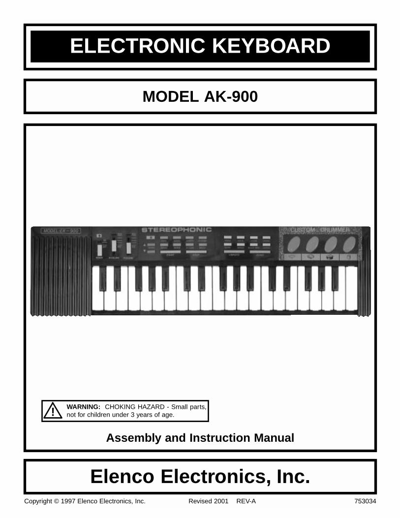
ELECTRONIC KEYBOARD
MODEL AK-900
Elenco Electronics, Inc.Copyright © 1997 Elenco Electronics, Inc. Revised 2001 REV-A 753034
Assembly and Instruction Manual
! WARNING: CHOKING HAZARD - Small parts,not for children under 3 years of age.
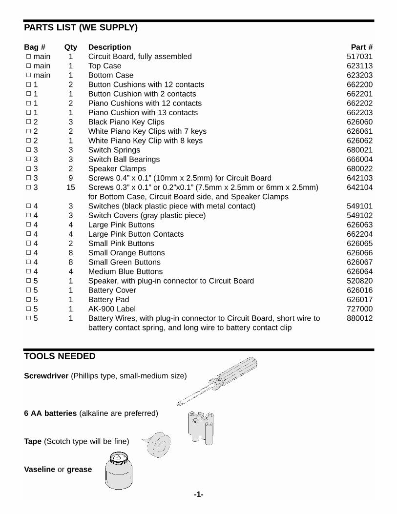
PARTS LIST (WE SUPPLY)
Bag # Qty Description Part #main 1 Circuit Board, fully assembled 517031main 1 Top Case 623113main 1 Bottom Case 6232031 2 Button Cushions with 12 contacts 6622001 1 Button Cushion with 2 contacts 6622011 2 Piano Cushions with 12 contacts 6622021 1 Piano Cushion with 13 contacts 6622032 3 Black Piano Key Clips 6260602 2 White Piano Key Clips with 7 keys 6260612 1 White Piano Key Clip with 8 keys 6260623 3 Switch Springs 6800213 3 Switch Ball Bearings 6660043 2 Speaker Clamps 6800223 9 Screws 0.4” x 0.1” (10mm x 2.5mm) for Circuit Board 6421033 15 Screws 0.3” x 0.1” or 0.2”x0.1” (7.5mm x 2.5mm or 6mm x 2.5mm) 642104
for Bottom Case, Circuit Board side, and Speaker Clamps4 3 Switches (black plastic piece with metal contact) 5491014 3 Switch Covers (gray plastic piece) 5491024 4 Large Pink Buttons 6260634 4 Large Pink Button Contacts 6622044 2 Small Pink Buttons 6260654 8 Small Orange Buttons 6260664 8 Small Green Buttons 6260674 4 Medium Blue Buttons 6260645 1 Speaker, with plug-in connector to Circuit Board 5208205 1 Battery Cover 6260165 1 Battery Pad 6260175 1 AK-900 Label 7270005 1 Battery Wires, with plug-in connector to Circuit Board, short wire to 880012
battery contact spring, and long wire to battery contact clip
TOOLS NEEDED
Screwdriver (Phillips type, small-medium size)
6 AA batteries (alkaline are preferred)
Tape (Scotch type will be fine)
Vaseline or grease
-1-
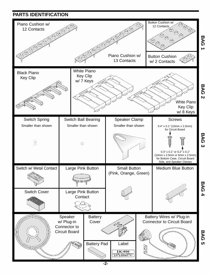
PARTS IDENTIFICATIONB
AG
1B
AG
2B
AG
3B
AG
4B
AG
5
Piano Cushion w/13 Contacts
Button Cushionw/ 2 Contacts
White PianoKey Clip
w/ 7 Keys
White PianoKey Clip
w/ 8 Keys
Switch Spring Switch Ball Bearing Speaker Clamp Screws
0.4” x 0.1” (10mm x 2.5mm)for Circuit Board
0.3” x 0.1” or 0.2” x 0.1”(10mm x 2.5mm or 6mm x 2.5mm)
for Bottom Case, Circuit BoardSide, and Speaker Clamps
Large Pink Button
Large Pink ButtonContact
Switch w/ Metal Contact
Switch Cover
Small Button(Pink, Orange, Green)
Medium Blue Button
Battery Wires w/ Plug-inConnector to Circuit Board
BatteryCover
Battery Pad Label
-2-
Piano Cushion w/12 Contacts
Button Cushion w/12 Contacts
Black PianoKey Clip
Speakerw/ Plug-in
Connector toCircuit Board
Smaller than shown Smaller than shown Smaller than shown
INTRODUCTIONThe AK-900 Electronic Keyboard is a electronic music system that you put together. It has 37 keys, 8 instrumentsounds (piano, flute, violin, organ, French horn, banjo, music box, guitar), 8 tempo adjustable rhythms (popmusic, disco, march, rhumba, tango, waltz, swing, ballad), 4 percussion effects (bass drum, close cymbals, opencymbals, indian snare drum), and 1 demonstration routine along with stereo, vibrato, and tempo effects. Mostof these sounds may be combined. The user can add his/her own music to a background tune. It uses 6 “AA”batteries (not included) or an optional AC/DC adapter. The Keyboard is mechanically assembled by the userwith no soldering required. The only tool needed is a phillips screwdriver.
Recommended for ages 10 and up. However, after the assembly and lesson are completed it will be suitablefor ages 3 and up.
WARNING:Choking Hazard: This kit contains small parts and should be kept out of the reach of small children untilit has been fully assembled. The optional AC/DC Adapter should always be kept away from smallchildren.
THEORY OF OPERATION
What is Sound? Sound is a variation in air pressure created by a mechanical vibration. (For a demonstration of this, lay one ofyour stereo speakers on the floor, place your hand on it, and turn up the volume. You should feel the speakervibrate. Now place a piece of paper on the speaker; if the volume is loud enough, you will see the paper vibrate).Since the vibrations usually last for some amount of time we call the result sound waves. If the vibration occursat a certain rate, then the sound wave will repeat itself at the same rate; we refer to this as the frequency of thesound wave. Nearly all sound waves have their energy spread unevenly across a range of frequencies. Youcan compare sound waves from your voice to waves in a pond. When you speak, the movements in your mouthcreate sound waves just as tossing a rock into the pond creates water waves. Sound waves travel through airas water waves travel across the pond. If someone is nearby, then their ears will feel the pressure variationscaused by your sound waves just as a small boat at the other side of the pond will feel the water waves. Whenyou say a word, you create a sound wave with energy at various frequencies, just as tossing a handful ofvarious-sized rocks into the pond will create a complicated water wave pattern.
Just as there are sound waves caused by mechanical vibrations, there are also electrical waves caused byelectrical variations. Just as sound waves travel through air, electrical waves travel through wires. A microphonesenses pressure variations from sound waves and creates electrical waves at the same frequencies. A speakeruses the energy in electrical waves to create mechanical vibrations (sound waves) at the same frequencies. Inaddition, electrical variations at high frequencies (referred to as radio frequencies) can be used to createelectromagnetic radio waves which travel through air and are used for many forms of communication.
The subject of music is one where the worlds of art and science come together. Unfortunately, theartistic/musician field works with qualities that depend on our feelings and so are difficult to express usingnumbers while science/engineering works with the opposite - clearly defined, measurable qualities. As a result,some of the terms used may seem confusing at first, but you will get used to them.
Let’s talk about frequency some more. Frequency is the number of repetitions per second (for sound orelectrical waves), expressed in units called hertz (Hz). The metric prefixes can be used, so 1000 repetitions persecond is 1 kilohertz (kHz) and 1,000,000 repetitions per second is 1 megahertz (MHz). The range offrequencies that can be heard by the human ear is approximately 16 to 16,000 Hz and is referred to as the audiorange. The musical world’s equivalent to frequency is pitch. The higher the frequency, the higher the pitch ofthe sound. Frequencies above 3000 Hz can be considered to provide treble tone. Frequencies about 300 Hzand below provide bass tone. Loudness (the musical term) or amplitude (the electronics term) is increased bysimply sending more electrical power to the speaker.
-3-
Fundamentals of MusicWhat is Music? Music is when vibrations (creating sound waves) occur in an orderly and controlled mannerforming a pattern with their energy concentrated at specific frequencies, usually pleasant to listen to. Noise iswhen the vibrations occur in an irregular manner with their energy spread across a wide range of frequencies,usually annoying to hear (static on a radio is a good example). Notice how some people refer to music that theydon’t like as noise.
Another way to think of this is that the ear tries to estimate the next sounds it will hear. Music with a beat, arhythm, and familiar instruments can be thought of as very predictable, hence we find it pleasant to listen to.Notice also that we always prefer familiar songs to music that we are hearing for the first time. Sudden, loud,unpredictable sounds (such as gunfire, a glass breaking, or an alarm clock) are very unnerving and unpleasant.Most electronic speech processing systems being developed use some form of speech prediction filters.
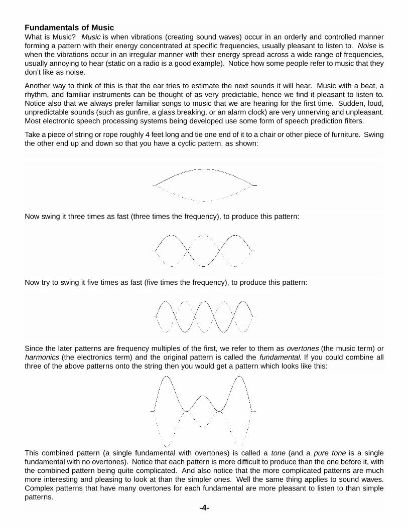
Take a piece of string or rope roughly 4 feet long and tie one end of it to a chair or other piece of furniture. Swingthe other end up and down so that you have a cyclic pattern, as shown:
-4-
Now swing it three times as fast (three times the frequency), to produce this pattern:
Now try to swing it five times as fast (five times the frequency), to produce this pattern:
Since the later patterns are frequency multiples of the first, we refer to them as overtones (the music term) orharmonics (the electronics term) and the original pattern is called the fundamental. If you could combine allthree of the above patterns onto the string then you would get a pattern which looks like this:
This combined pattern (a single fundamental with overtones) is called a tone (and a pure tone is a singlefundamental with no overtones). Notice that each pattern is more difficult to produce than the one before it, withthe combined pattern being quite complicated. And also notice that the more complicated patterns are muchmore interesting and pleasing to look at than the simpler ones. Well the same thing applies to sound waves.Complex patterns that have many overtones for each fundamental are more pleasant to listen to than simplepatterns.
All traditional music instruments use this principle, with the instrument shapes and materials perfected throughthe years to produce many overtones for each fundamental chord or key that is played by the user. Grandpianos sound better than upright pianos since their larger shape enables them to produce more overtones,especially at lower frequencies. Concert halls sound better than small rooms because they are designed forbest overtone performance and to take advantage of the fact that sound waves can reflect off walls to producedifferent overtone relationships between both of your ears. The same thing applies to stereo sound. You mayhave heard the term acoustics, this is the science of designing rooms for best sound effects.
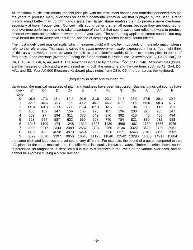
The most widely used musical scale (which measures pitch) will now be introduced; for more information pleaserefer to the references. This scale is called the equal temperament scale, expressed in hertz. You might thinkof this as a conversion table between the artistic and scientific worlds since it expresses pitch in terms offrequency. Each overtone (overtone 0 being the fundamental) is divided into 12 semitones: C, C# (“C-flat”), D,
D#, E, F, F#, G, G#, A, A#, and B. The semitones increase by the ratio 12√2, or 1.05946. Musical notes (tones)are the measure of pitch and are expressed using both the semitone and the overtone, such as A3, G#4, D6,A#1, and E2. Your AK-900 Electronic Keyboard plays notes from C3 to C6, in order across the keyboard.
(frequency in hertz and rounded off)
Up to now, the musical measures of pitch and loudness have been discussed. But many musical sounds have
the same pitch and loudness and yet sound very different. For example, the sound of a guitar compared to thatof a piano for the same musical note. The difference is a quality known as timbre. Timbre describes how a soundis perceived, its roughness. Scientifically it is due to differences in the levels of the various overtones, and socannot be expressed using a single number.
over- C C# D D# E F F# G G# A A# Btone
0 16.4 17.3 18.4 19.4 20.6 21.8 23.1 24.5 26.0 27.5 29.1 30.91 32.7 34.6 36.7 38.9 41.2 45.7 46.2 49.0 51.9 55.0 58.3 61.72 65.4 69.3 73.4 77.8 82.4 87.3 92.5 98.0 104 110 117 1233 130 139 147 156 165 175 185 196 208 220 233 2474 262 27 294 311 330 349 370 392 415 440 466 4945 523 554 587 622 659 698 740 784 831 880 932 9886 1047 1109 174 1245 1319 1397 1480 1568 1661 1760 1865 19767 2093 2217 2344 2489 2637 2794 2960 3136 3322 3520 3729 39518 4186 435 4698 4978 5274 5588 5920 6271 6645 7040 7459 79029 8372 8870 9397 9956 10548 11175 11840 12542 13290 14080 14917 15804
-5-
-6-
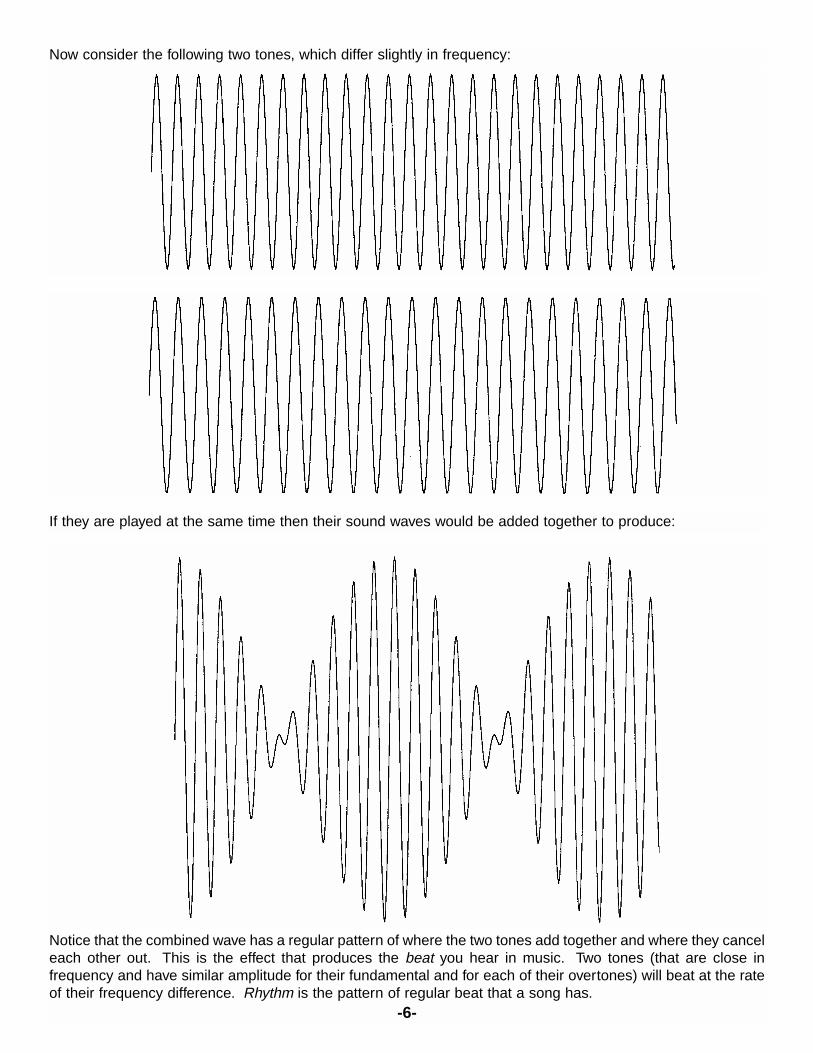
Now consider the following two tones, which differ slightly in frequency:
If they are played at the same time then their sound waves would be added together to produce:
Notice that the combined wave has a regular pattern of where the two tones add together and where they canceleach other out. This is the effect that produces the beat you hear in music. Two tones (that are close infrequency and have similar amplitude for their fundamental and for each of their overtones) will beat at the rateof their frequency difference. Rhythm is the pattern of regular beat that a song has.
-7-
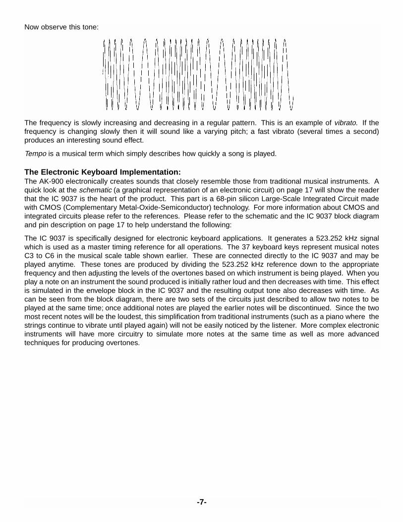
Now observe this tone:
The frequency is slowly increasing and decreasing in a regular pattern. This is an example of vibrato. If thefrequency is changing slowly then it will sound like a varying pitch; a fast vibrato (several times a second)produces an interesting sound effect.
Tempo is a musical term which simply describes how quickly a song is played.
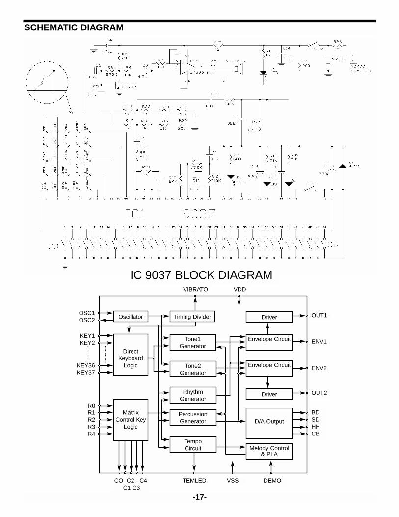
The Electronic Keyboard Implementation:The AK-900 electronically creates sounds that closely resemble those from traditional musical instruments. Aquick look at the schematic (a graphical representation of an electronic circuit) on page 17 will show the readerthat the IC 9037 is the heart of the product. This part is a 68-pin silicon Large-Scale Integrated Circuit madewith CMOS (Complementary Metal-Oxide-Semiconductor) technology. For more information about CMOS andintegrated circuits please refer to the references. Please refer to the schematic and the IC 9037 block diagramand pin description on page 17 to help understand the following:
The IC 9037 is specifically designed for electronic keyboard applications. It generates a 523.252 kHz signalwhich is used as a master timing reference for all operations. The 37 keyboard keys represent musical notesC3 to C6 in the musical scale table shown earlier. These are connected directly to the IC 9037 and may beplayed anytime. These tones are produced by dividing the 523.252 kHz reference down to the appropriatefrequency and then adjusting the levels of the overtones based on which instrument is being played. When youplay a note on an instrument the sound produced is initially rather loud and then decreases with time. This effectis simulated in the envelope block in the IC 9037 and the resulting output tone also decreases with time. Ascan be seen from the block diagram, there are two sets of the circuits just described to allow two notes to beplayed at the same time; once additional notes are played the earlier notes will be discontinued. Since the twomost recent notes will be the loudest, this simplification from traditional instruments (such as a piano where thestrings continue to vibrate until played again) will not be easily noticed by the listener. More complex electronicinstruments will have more circuitry to simulate more notes at the same time as well as more advancedtechniques for producing overtones.
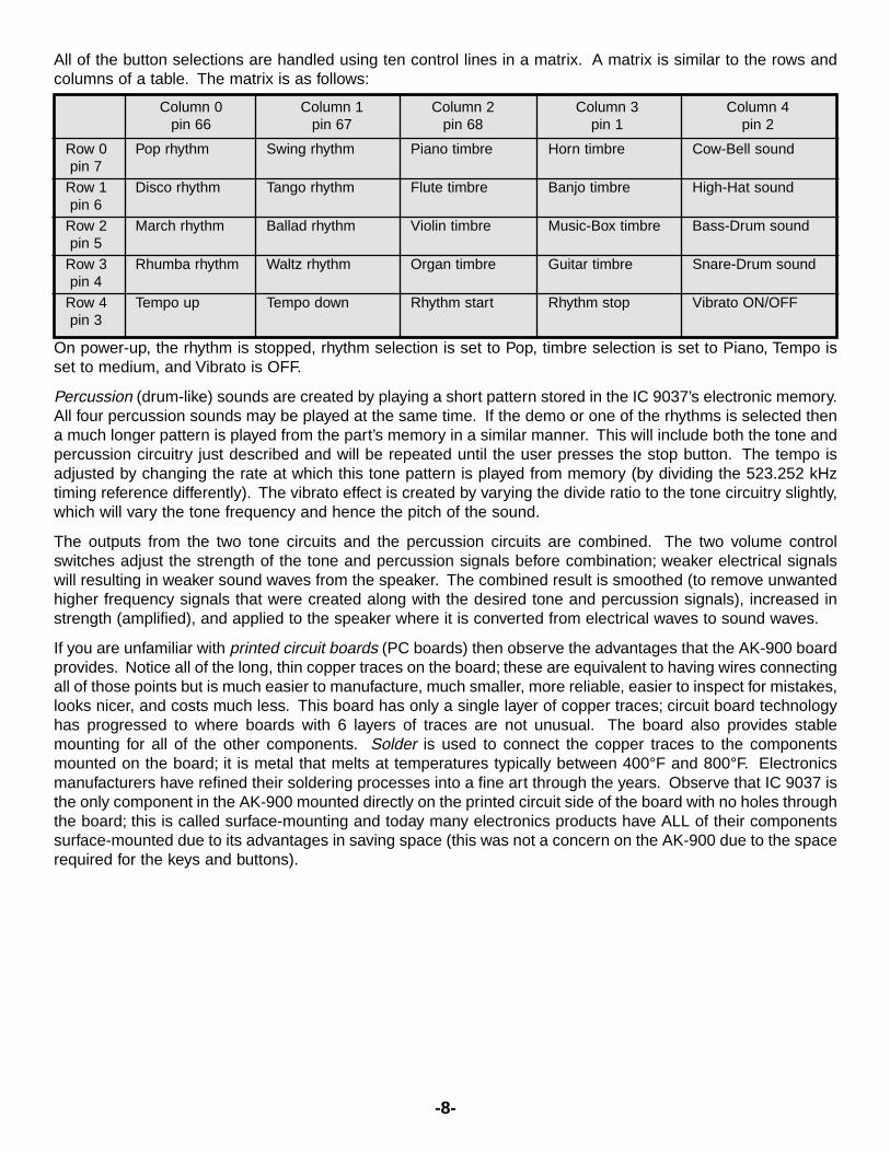
All of the button selections are handled using ten control lines in a matrix. A matrix is similar to the rows andcolumns of a table. The matrix is as follows:
On power-up, the rhythm is stopped, rhythm selection is set to Pop, timbre selection is set to Piano, Tempo isset to medium, and Vibrato is OFF.
Percussion (drum-like) sounds are created by playing a short pattern stored in the IC 9037’s electronic memory.All four percussion sounds may be played at the same time. If the demo or one of the rhythms is selected thena much longer pattern is played from the part’s memory in a similar manner. This will include both the tone andpercussion circuitry just described and will be repeated until the user presses the stop button. The tempo isadjusted by changing the rate at which this tone pattern is played from memory (by dividing the 523.252 kHztiming reference differently). The vibrato effect is created by varying the divide ratio to the tone circuitry slightly,which will vary the tone frequency and hence the pitch of the sound.
The outputs from the two tone circuits and the percussion circuits are combined. The two volume controlswitches adjust the strength of the tone and percussion signals before combination; weaker electrical signalswill resulting in weaker sound waves from the speaker. The combined result is smoothed (to remove unwantedhigher frequency signals that were created along with the desired tone and percussion signals), increased instrength (amplified), and applied to the speaker where it is converted from electrical waves to sound waves.
If you are unfamiliar with printed circuit boards (PC boards) then observe the advantages that the AK-900 boardprovides. Notice all of the long, thin copper traces on the board; these are equivalent to having wires connectingall of those points but is much easier to manufacture, much smaller, more reliable, easier to inspect for mistakes,looks nicer, and costs much less. This board has only a single layer of copper traces; circuit board technologyhas progressed to where boards with 6 layers of traces are not unusual. The board also provides stablemounting for all of the other components. Solder is used to connect the copper traces to the componentsmounted on the board; it is metal that melts at temperatures typically between 400°F and 800°F. Electronicsmanufacturers have refined their soldering processes into a fine art through the years. Observe that IC 9037 isthe only component in the AK-900 mounted directly on the printed circuit side of the board with no holes throughthe board; this is called surface-mounting and today many electronics products have ALL of their componentssurface-mounted due to its advantages in saving space (this was not a concern on the AK-900 due to the spacerequired for the keys and buttons).
Column 0 Column 1 Column 2 Column 3 Column 4pin 66 pin 67 pin 68 pin 1 pin 2
Row 0 Pop rhythm Swing rhythm Piano timbre Horn timbre Cow-Bell soundpin 7
Row 1 Disco rhythm Tango rhythm Flute timbre Banjo timbre High-Hat soundpin 6
Row 2 March rhythm Ballad rhythm Violin timbre Music-Box timbre Bass-Drum soundpin 5
Row 3 Rhumba rhythm Waltz rhythm Organ timbre Guitar timbre Snare-Drum soundpin 4
Row 4 Tempo up Tempo down Rhythm start Rhythm stop Vibrato ON/OFFpin 3
-8-
ASSEMBLY INSTRUCTIONS
1. Take a look at each of the parts bags and compare to the Parts List. Be sure that nothing was damagedduring shipping and handling. Contact Elenco Electronics if you have any problems. DO NOT contact yourplace of purchase as they will not be able to help you.
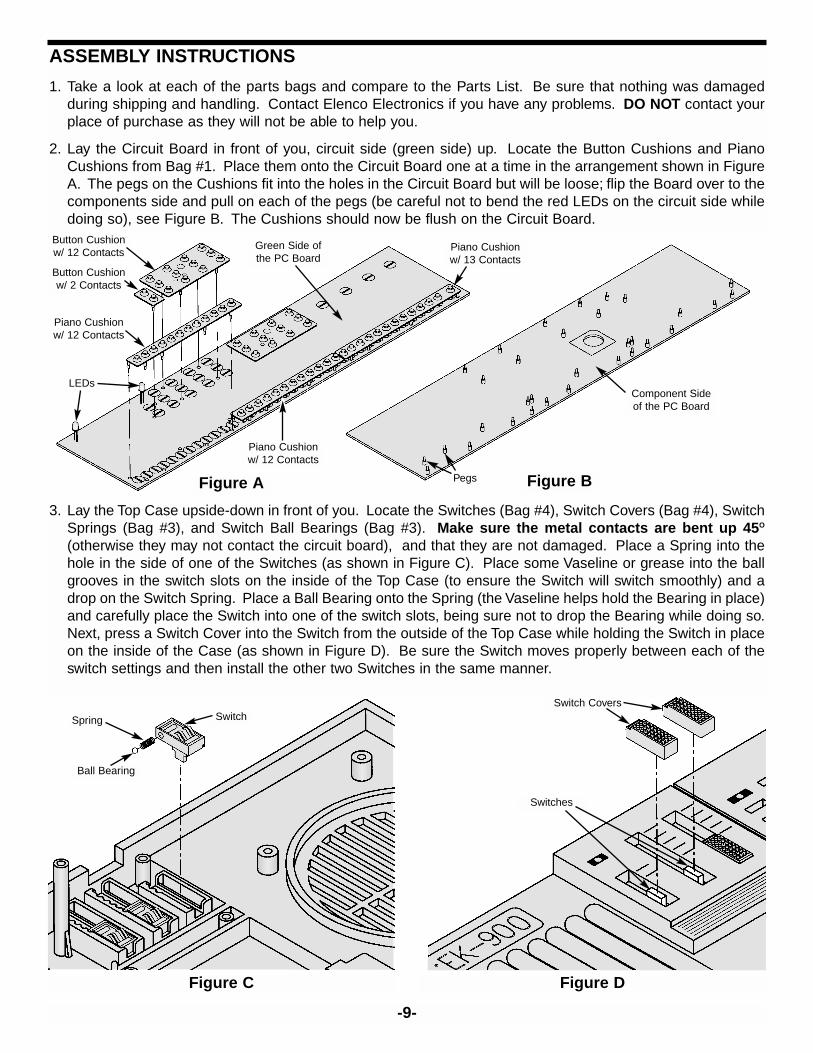
2. Lay the Circuit Board in front of you, circuit side (green side) up. Locate the Button Cushions and PianoCushions from Bag #1. Place them onto the Circuit Board one at a time in the arrangement shown in FigureA. The pegs on the Cushions fit into the holes in the Circuit Board but will be loose; flip the Board over to thecomponents side and pull on each of the pegs (be careful not to bend the red LEDs on the circuit side whiledoing so), see Figure B. The Cushions should now be flush on the Circuit Board.
-9-
Figure C Figure D
Figure A Figure B
Button Cushionw/ 12 Contacts
Button Cushionw/ 2 Contacts
Piano Cushionw/ 12 Contacts
Piano Cushionw/ 12 Contacts
Piano Cushionw/ 13 Contacts
Green Side ofthe PC Board
Component Sideof the PC Board
LEDs
Pegs
3. Lay the Top Case upside-down in front of you. Locate the Switches (Bag #4), Switch Covers (Bag #4), SwitchSprings (Bag #3), and Switch Ball Bearings (Bag #3). Make sure the metal contacts are bent up 45O
(otherwise they may not contact the circuit board), and that they are not damaged. Place a Spring into thehole in the side of one of the Switches (as shown in Figure C). Place some Vaseline or grease into the ballgrooves in the switch slots on the inside of the Top Case (to ensure the Switch will switch smoothly) and adrop on the Switch Spring. Place a Ball Bearing onto the Spring (the Vaseline helps hold the Bearing in place)and carefully place the Switch into one of the switch slots, being sure not to drop the Bearing while doing so.Next, press a Switch Cover into the Switch from the outside of the Top Case while holding the Switch in placeon the inside of the Case (as shown in Figure D). Be sure the Switch moves properly between each of theswitch settings and then install the other two Switches in the same manner.
Ball Bearing
Spring SwitchSwitch Covers
Switches
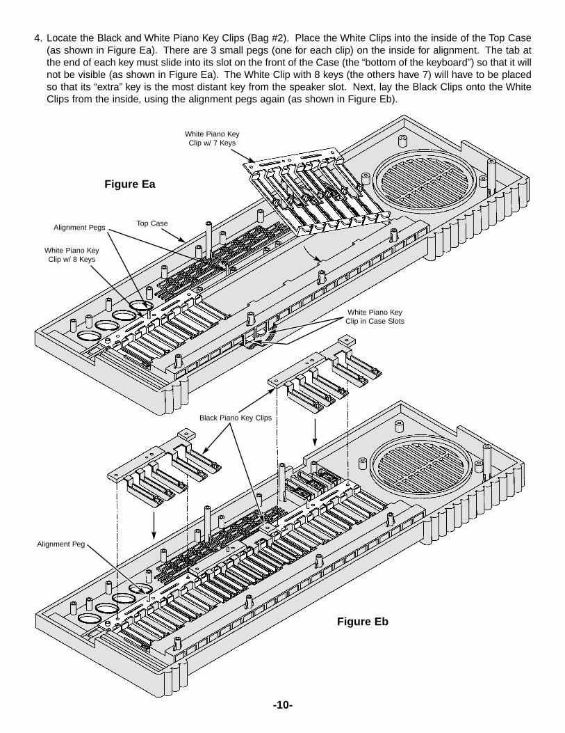
4. Locate the Black and White Piano Key Clips (Bag #2). Place the White Clips into the inside of the Top Case(as shown in Figure Ea). There are 3 small pegs (one for each clip) on the inside for alignment. The tab atthe end of each key must slide into its slot on the front of the Case (the “bottom of the keyboard”) so that it willnot be visible (as shown in Figure Ea). The White Clip with 8 keys (the others have 7) will have to be placedso that its “extra” key is the most distant key from the speaker slot. Next, lay the Black Clips onto the WhiteClips from the inside, using the alignment pegs again (as shown in Figure Eb).
-10-
White Piano KeyClip w/ 7 Keys
White Piano KeyClip w/ 8 Keys
Top Case
Figure Ea
Alignment Pegs
White Piano KeyClip in Case Slots
Figure Eb
Alignment Peg
Black Piano Key Clips
-11-
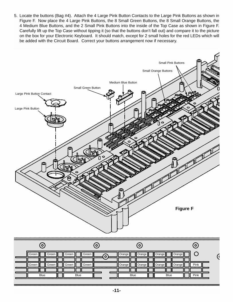
5. Locate the buttons (Bag #4). Attach the 4 Large Pink Button Contacts to the Large Pink Buttons as shown inFigure F. Now place the 4 Large Pink Buttons, the 8 Small Green Buttons, the 8 Small Orange Buttons, the4 Medium Blue Buttons, and the 2 Small Pink Buttons into the inside of the Top Case as shown in Figure F.Carefully lift up the Top Case without tipping it (so that the buttons don’t fall out) and compare it to the pictureon the box for your Electronic Keyboard. It should match, except for 2 small holes for the red LEDs which willbe added with the Circuit Board. Correct your buttons arrangement now if necessary.
Green Green Green Green
Green Green Green Green
Blue Blue
Orange Orange Orange Orange
Orange Orange Orange Orange
Blue Blue
Pink
Pink
Large Pink Button
Small Green Button
Medium Blue Button
Small Orange Buttons
Small Pink Buttons
Large Pink Button Contact
Figure F
-12-
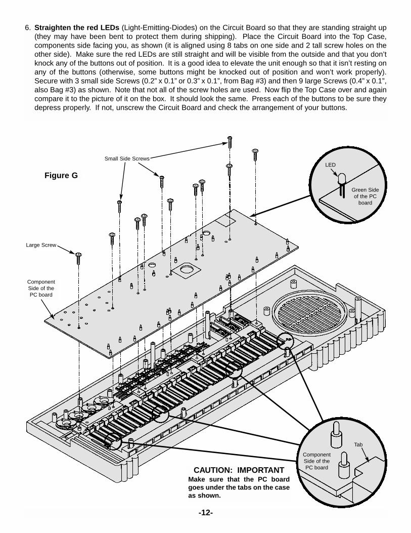
6. Straighten the red LEDs (Light-Emitting-Diodes) on the Circuit Board so that they are standing straight up(they may have been bent to protect them during shipping). Place the Circuit Board into the Top Case,components side facing you, as shown (it is aligned using 8 tabs on one side and 2 tall screw holes on theother side). Make sure the red LEDs are still straight and will be visible from the outside and that you don’tknock any of the buttons out of position. It is a good idea to elevate the unit enough so that it isn’t resting onany of the buttons (otherwise, some buttons might be knocked out of position and won’t work properly).Secure with 3 small side Screws (0.2” x 0.1” or 0.3” x 0.1”, from Bag #3) and then 9 large Screws (0.4” x 0.1”,also Bag #3) as shown. Note that not all of the screw holes are used. Now flip the Top Case over and againcompare it to the picture of it on the box. It should look the same. Press each of the buttons to be sure theydepress properly. If not, unscrew the Circuit Board and check the arrangement of your buttons.
Figure G
Small Side Screws
Large Screw
ComponentSide of thePC board
CAUTION: IMPORTANTMake sure that the PC boardgoes under the tabs on the caseas shown.
ComponentSide of thePC board
Tab
Green Sideof the PC
board
LED
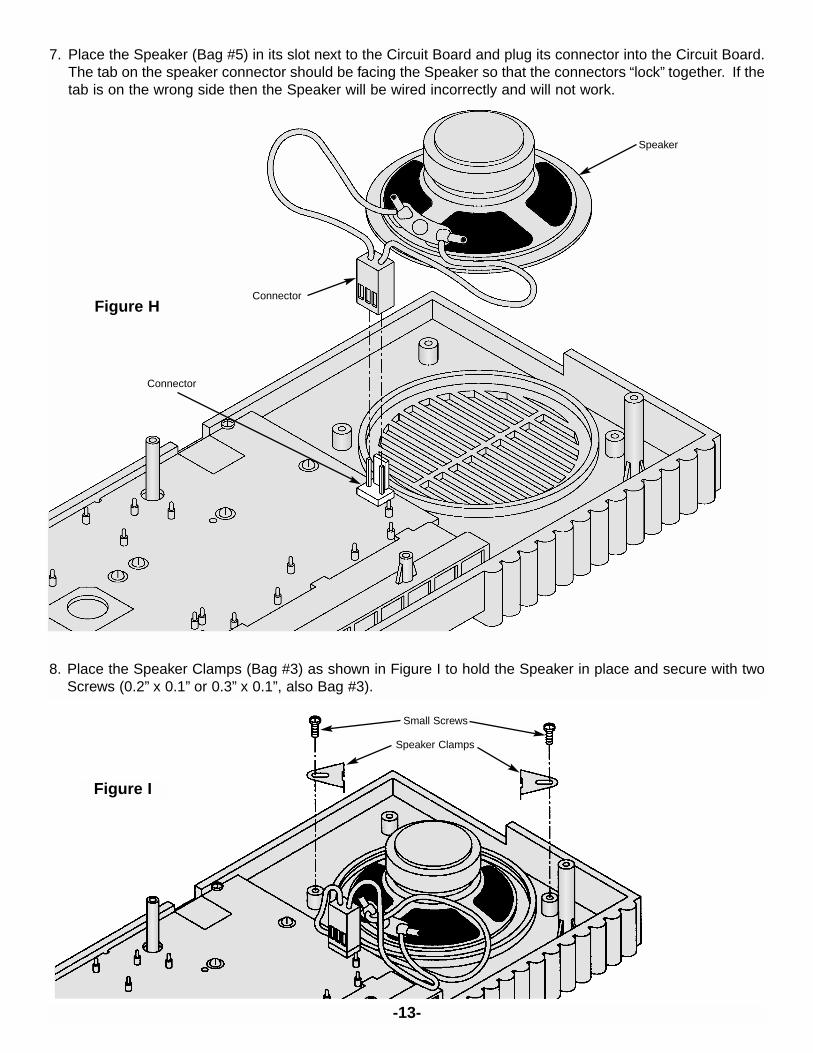
7. Place the Speaker (Bag #5) in its slot next to the Circuit Board and plug its connector into the Circuit Board.The tab on the speaker connector should be facing the Speaker so that the connectors “lock” together. If thetab is on the wrong side then the Speaker will be wired incorrectly and will not work.
8. Place the Speaker Clamps (Bag #3) as shown in Figure I to hold the Speaker in place and secure with twoScrews (0.2” x 0.1” or 0.3” x 0.1”, also Bag #3).
-13-
Figure H
Speaker
Connector
Connector
Figure I
Speaker Clamps
Small Screws
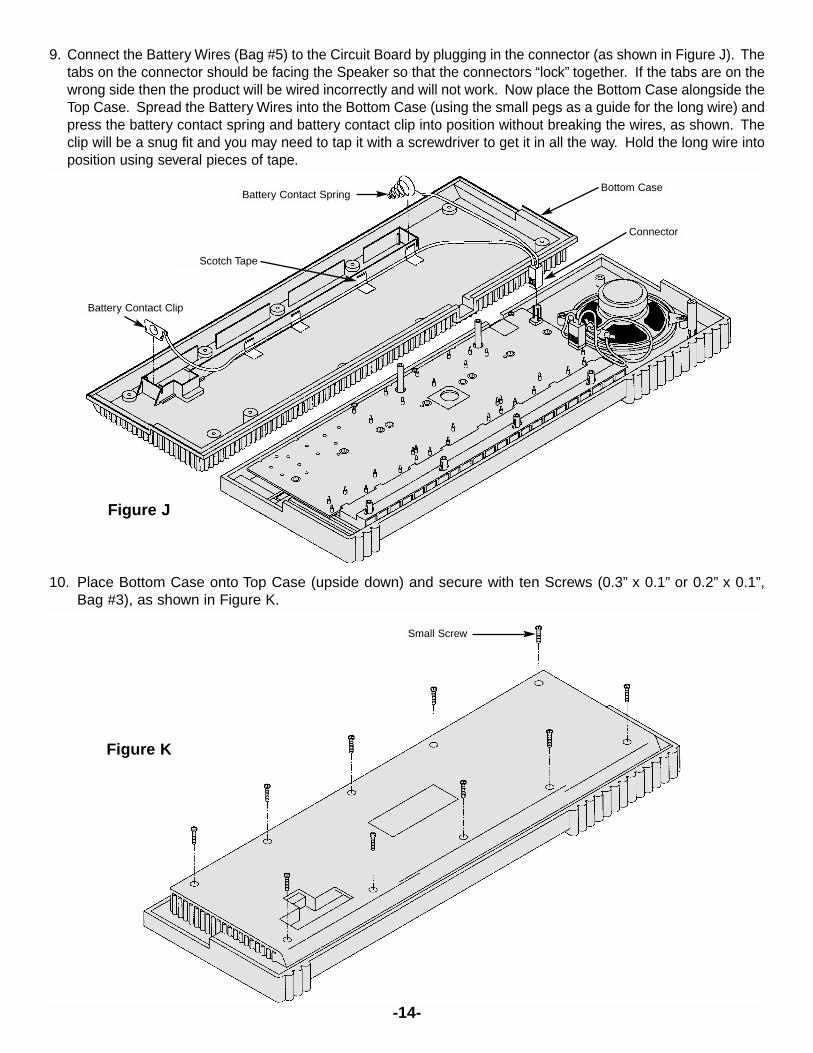
9. Connect the Battery Wires (Bag #5) to the Circuit Board by plugging in the connector (as shown in Figure J). Thetabs on the connector should be facing the Speaker so that the connectors “lock” together. If the tabs are on thewrong side then the product will be wired incorrectly and will not work. Now place the Bottom Case alongside theTop Case. Spread the Battery Wires into the Bottom Case (using the small pegs as a guide for the long wire) andpress the battery contact spring and battery contact clip into position without breaking the wires, as shown. Theclip will be a snug fit and you may need to tap it with a screwdriver to get it in all the way. Hold the long wire intoposition using several pieces of tape.
-14-
10. Place Bottom Case onto Top Case (upside down) and secure with ten Screws (0.3” x 0.1” or 0.2” x 0.1”,Bag #3), as shown in Figure K.
Figure K
Small Screw
Figure J
Battery Contact Clip
Battery Contact Spring
Scotch Tape
Bottom Case
Connector
OPERATING INSTRUCTIONS
Turn the unit on and adjust the speaker volume as needed (you may adjust the rhythm and master volumesseparately). You may use the keyboard and custom drummer (the big pink buttons) by themselves or combinedwith background music. The orange buttons provide background dance music; press one of them and then thestart button. The blue DEMO button plays the demonstration tune “Greensleeves”; to stop the demo, press theDEMO button again. The green buttons select which instrument the keyboard is simulating (piano, flute, violin,organ, french horn, banjo, music box, guitar). Use the small pink buttons to change the tempo of the demo orthe dance music. The Vibrato button turns the vibrato effect ON/OFF.
This product operates with six AA batteries. The unit will not sound as usual if the batteries are weak, in thiscase try changing the batteries. For longer battery life take out the batteries if the unit will not be used for a longtime and use alkaline batteries.
You may also operate this product with an AC/DC Adapter that has a 9V output voltage and 400mA currentrating. This may be purchased through Elenco Electronics or at your local electronics store.
WARNING FOR USE OF AC/DC ADAPTER:The Adapter should be regularly examined for potential hazards of damaged cable, plug, and enclosure. In theevent of such damage the adapter must not be used until such damage has been properly removed.
The Adapter must comply with CEE publication -15.
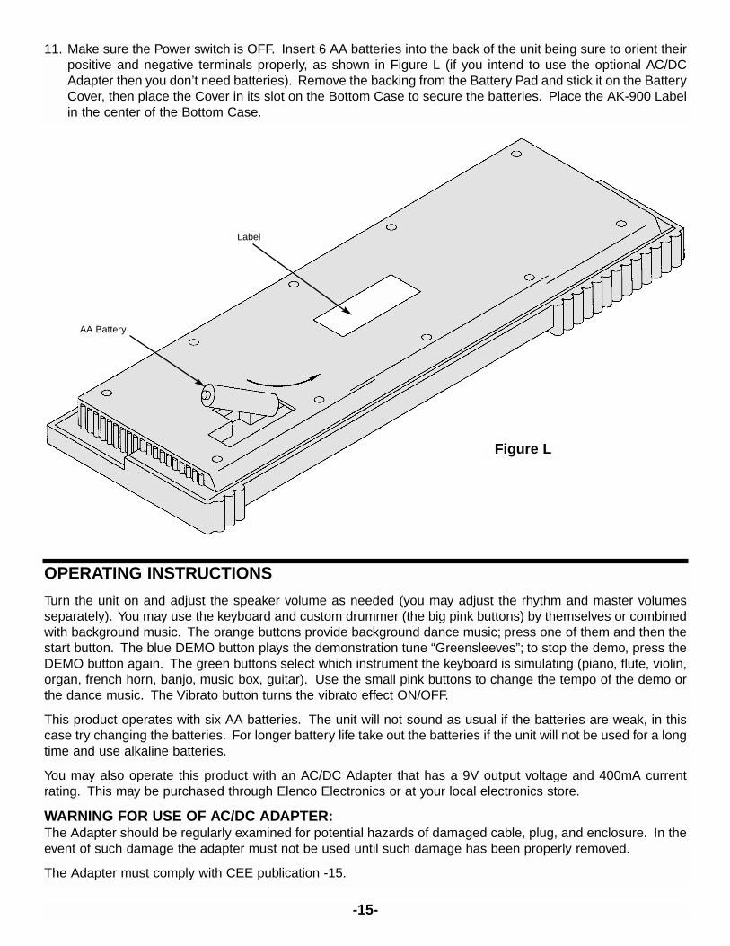
11. Make sure the Power switch is OFF. Insert 6 AA batteries into the back of the unit being sure to orient theirpositive and negative terminals properly, as shown in Figure L (if you intend to use the optional AC/DCAdapter then you don’t need batteries). Remove the backing from the Battery Pad and stick it on the BatteryCover, then place the Cover in its slot on the Bottom Case to secure the batteries. Place the AK-900 Labelin the center of the Bottom Case.
-15-
Figure L
Label
AA Battery
-16-
QUIZ
1. Sound waves travel through air just as electrical waves travel through __________.
2. A microphone converts sound waves into __________ __________.
3. Pitch is the musician’s term for __________.
4. Mechanical variations in a loud and unpredictable manner will seem more like noise than __________ to alistener.
5. Traditional music instruments produce many __________ for each fundamental.
6. Musical note G5 has a frequency of __________ Hz (refer to the musical scale).
7. The main properties of a musical sound are loudness, pitch, and __________.
8. Two tones, with frequencies of 250 Hz and 255 Hz and similar loudness, will produce a __________ whenplayed together.
9. ________ is adjusted in the AK-900 by changing the rate at which a tone pattern is played from memory.
10. Long, thin copper traces connect electronic components on __________ __________ __________.
Answers:1.wires;2.electrical waves;3.frequency;4.music;5.overtones;6.784;7.timbre;8.beat;9.tempo;10.printed circuit boards.
TROUBLESHOOTING GUIDE
Symptom: Keyboard doesn’t work at all.
• Make sure that the batteries are new and that they are installed with the correct polarity. If using the optionalAC/DC Adapter then make sure it is undamaged and plugged in.
• Make sure the ON/OFF switch is ON. Make sure the volume controls are not at the lowest setting.
• If the red LED next to the ON/OFF switch is off then flip the ON/OFF switch several times, pressing it hard.
• Be sure that none of the wiring connections were broken, are contacting any other metal (creating a “shortcircuit”), or are wired wrong.
• Be sure that there is no physical damage to the Main PCB.
Symptom: Sounds don’t sound normal, as if out-of-tune.
• Make sure that the batteries are new and that they are all installed with the correct polarity. Alkaline or carbonzinc batteries are preferred.
Symptom: Some of the keys, buttons, or switches do not work.
• Be sure all the keys, buttons, and switches are properly situated as in assembly steps 2-5.
• Examine the Cushions on the Circuit Board, make sure they are laying flat on the Board and that they are notdamaged.
• Be sure there is no physical damage to the components or copper traces on the Circuit Board.
Note: Contact Elenco Electronics, Inc. at (847) 541-3800 or e-mail us at [email protected] if you needfurther assistance. DO NOT contact your place of purchase as they will not be able to help you.
-17-
SCHEMATIC DIAGRAM
OscillatorOSC1OSC2
KEY1KEY2
KEY36KEY37
R0R1R2R3R4
DirectKeyboard
Logic
MatrixControl Key
Logic
Timing Divider
Tone1Generator
Tone2Generator
RhythmGenerator
PercussionGenerator
TempoCircuit Melody Control
& PLA
D/A Output
Driver
Envelope Circuit
Envelope Circuit
Driver OUT1
ENV1
ENV2
OUT2
BDSDHHCB
VIBRATO VDD
DEMOVSSTEMLEDCO C2 C4C1 C3
IC 9037 BLOCK DIAGRAM
-18-
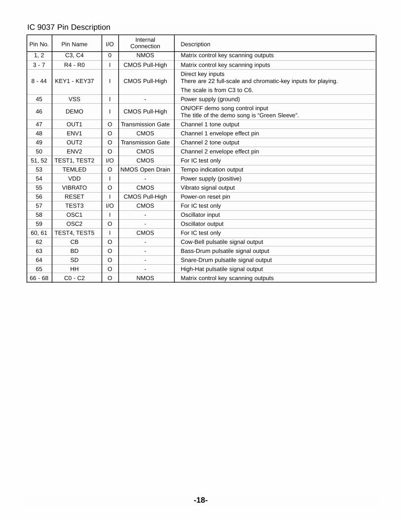
IC 9037 Pin Description
InternalPin No. Pin Name I/O Connection Description
1, 2 C3, C4 0 NMOS Matrix control key scanning outputs
3 - 7 R4 - R0 I CMOS Pull-High Matrix control key scanning inputs
Direct key inputs8 - 44 KEY1 - KEY37 I CMOS Pull-High There are 22 full-scale and chromatic-key inputs for playing.
The scale is from C3 to C6.
45 VSS I - Power supply (ground)
46 DEMO I CMOS Pull-High ON/OFF demo song control inputThe title of the demo song is “Green Sleeve”.
47 OUT1 O Transmission Gate Channel 1 tone output
48 ENV1 O CMOS Channel 1 envelope effect pin
49 OUT2 O Transmission Gate Channel 2 tone output
50 ENV2 O CMOS Channel 2 envelope effect pin
51, 52 TEST1, TEST2 I/O CMOS For IC test only
53 TEMLED O NMOS Open Drain Tempo indication output
54 VDD I - Power supply (positive)
55 VIBRATO O CMOS Vibrato signal output
56 RESET I CMOS Pull-High Power-on reset pin
57 TEST3 I/O CMOS For IC test only
58 OSC1 I - Oscillator input
59 OSC2 O - Oscillator output
60, 61 TEST4, TEST5 I CMOS For IC test only
62 CB O - Cow-Bell pulsatile signal output
63 BD O - Bass-Drum pulsatile signal output
64 SD O - Snare-Drum pulsatile signal output
65 HH O - High-Hat pulsatile signal output
66 - 68 C0 - C2 O NMOS Matrix control key scanning outputs
-19-
GLOSSARY OF TERMS
Acoustics The science of designing rooms for best sound effects.
Amplitude A measure of the strength of an electronic signal.
Audio The range of sounds that can be heard by the ear.
Bass Tones Low frequency sound, usually below 300 Hz.
Beat A pattern in musical rhythm caused by 2 tones at different frequencies(usually close), so that they regularly form highs and lows in loudness.
Equal Temperament Scale A musical scale for measuring pitch.
Electrical Waves Electrical energy similar to sound waves but caused by electricalvibrations and traveling through wires.
Electromagnetic Radio Waves Electromagnetic energy similar to electrical waves but caused by electricalvibrations at higher frequencies and traveling through air; used for manyforms of communications.
Frequency The rate at which a pattern or wave repeats itself.
Fundamental The lowest (and usually the loudest) frequency in a tone.
Harmonics The electronics term for frequencies that are exact multiples of a lowerfrequency (the fundamental) produced by the same source.
Hertz (Hz) The number of repetitions per second.
Integrated Circuit An electronic circuit that has been made very, very small.
Kilohertz (kHz) The number of repetitions per second, expressed in thousands.
Light-Emitting-Diodes (LEDs) A device which converts electrical energy into light.
Loudness A measure of the strength of sound waves, also called volume.
Megahertz (MHz) The number of repetitions per second, expressed in millions.
Metric System An international system of measurement.
Microphone A device which converts sound waves into electrical waves.
Musical Note A measure of the pitch of a sound, expressed using semitones andovertones in a musical scale.
Noise Mechanical vibrations (sound waves) occurring in an irregular manner withtheir energy spread across a wide range of frequencies, usually annoyingto hear.
Overtones The musical term for frequencies that are exact multiples of a lowerfrequency (the fundamental) produced by the same source.
Percussion Sounds Drum-like, hitting one thing against another.
Pitch The musical world’s term for frequency, expressed using a musical scale;may be perceived differently between people.
Printed Circuit Board A board for mounting electronics components that has copper traces“printed” on the surface for connecting the components instead of usingwires.
Pure Tone A fundamental frequency with no overtones.
Rhythm The pattern of regular beat that a song has.
Schematic A graphical representation of an electronic circuit.
Semitones The division of notes within each overtone on the musical scale.
Solder A metal that melts at temperatures between 400°F and 800°F; it is used toconnect electronic components to each other or to copper traces onprinted circuit boards.
Sound A variation in air pressure caused by a mechanical vibration; our ears canusually feel this.
Sound Waves Air pressure waves caused by mechanical vibrations.
Speaker A device which converts electrical waves into sound waves.
Tempo A musical term which describes how quickly a song is played.
Timbre The quality of sound that separates tones equal in pitch and loudness butperceived differently, it is due to differences in the levels of the variousovertones.
Tone A sound with a fundamental and overtones.
Treble Tones High frequency sound, usually above 3000 Hz.
Vibrato When the frequency of a tone is slowing increasing and decreasing at aregular rate.
FOR FURTHER READING(These are available through Elenco Electronics Inc., unless stated otherwise).
Evans A. (1992). Making Sense of Sound. Sams (61026)
Sundberg J. (1991). The Science of Musical Sounds. Academic Press. Not available through ElencoElectronics, try your local bookstore or library.
Pierce J. R. (1983). The Science of Musical Sound. Scientific American Books. Not available through ElencoElectronics, try your local bookstore or library.
Douglas A. (1976). The Electronic Musical Instrument Manual. Tab Books (#832). Not available through ElencoElectronics, try your local bookstore or library.
Penfold R. A. (1995). Music Projects. Sams (67052)
Rezurch I. (1996). Electronics Terminology. Sams (67013)
Mileaf H. (1978). Electricity 1-7. Sams (159523)
Johnson J. R. (1994). Schematic Diagrams. Sams (61059)
Kamichik S. (1996). Digital Electronics. Sams (61075)
-20-

Here are some other exciting projects from Elenco you can build.
SOLDERLESS KITS35mm Camera Kit with training course
Model AK-540
Now you can learn all about photography with our newCamera Kit. Our training manual will teach you everythingyou need to know about light, film, speed, exposure,development, and much more. And best of all, you’ll have aworking camera “you built” when you’re finished.
Talking Clock Kit with training course
Model AK-220
This easy-to-build kit will teach you how electronic voicesare made. Model AK-220 uses analog hands to display timeand has hourly reports. Wake up to a rooster crowing in themorning.
RADIO CONTROLLED CAR KITThe Turbo King is our newest solderless kit. R/C cars are the hottestthing going, and you can build your own from the ground up.You’ll learn all about gears, motors, RF frequency and morefrom our detailed assembly and training manual. Beforeyou know it, you’ll be ready to race!
7 Radio Functions.
Flashing Top Light.
Single Channel.
Model AK-870
-21-
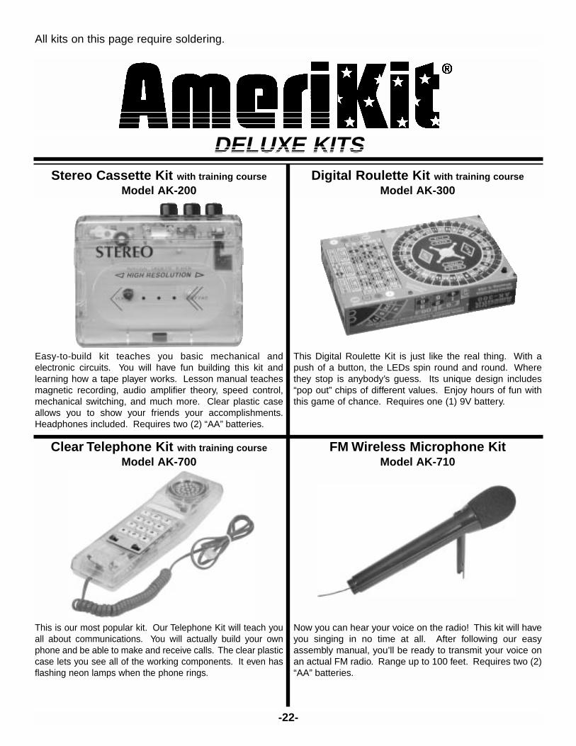
DELUXE KITSStereo Cassette Kit with training course
Model AK-200
Easy-to-build kit teaches you basic mechanical andelectronic circuits. You will have fun building this kit andlearning how a tape player works. Lesson manual teachesmagnetic recording, audio amplifier theory, speed control,mechanical switching, and much more. Clear plastic caseallows you to show your friends your accomplishments.Headphones included. Requires two (2) “AA” batteries.
Digital Roulette Kit with training course
Model AK-300
This Digital Roulette Kit is just like the real thing. With apush of a button, the LEDs spin round and round. Wherethey stop is anybody’s guess. Its unique design includes“pop out” chips of different values. Enjoy hours of fun withthis game of chance. Requires one (1) 9V battery.
Clear Telephone Kit with training course
Model AK-700
This is our most popular kit. Our Telephone Kit will teach youall about communications. You will actually build your ownphone and be able to make and receive calls. The clear plasticcase lets you see all of the working components. It even hasflashing neon lamps when the phone rings.
FM Wireless Microphone KitModel AK-710
Now you can hear your voice on the radio! This kit will haveyou singing in no time at all. After following our easyassembly manual, you’ll be ready to transmit your voice onan actual FM radio. Range up to 100 feet. Requires two (2)“AA” batteries.
-22-
All kits on this page require soldering.

Elenco Electronics, Inc.150 W. Carpenter Avenue
Wheeling, IL 60090(847) 541-3800
http://www.elenco.come-mail: [email protected]


![Untitled-1 [] · Cushion: M*2 Cushion: M*2 Cushion: M*1 Cushion: M*1 Cushion: M*2 Cushion: M*3 Cushion: M*4 Cushion: S*3 Cushion: S*2 Cushion: S*1 Cushion: M*3 S*2 Cushion: M*2 S*1](https://static.fdocuments.us/doc/165x107/5fcbbac82e8c411bf55b5c66/untitled-1-cushion-m2-cushion-m2-cushion-m1-cushion-m1-cushion-m2.jpg)