Electronic Digital Theodolite - Sokkia · PDF file2. PRECAUTIONS a) When the DT5 is not used...
24
.ni " -, SURVEYING INSTRUMENTS,'; SQKKIJ\ DT5/DT5S DT5A/DT5AS Electronic Digital Theodolite OPERATOR'S MANUAL
Transcript of Electronic Digital Theodolite - Sokkia · PDF file2. PRECAUTIONS a) When the DT5 is not used...

.ni
"
-,
SURVEYING INSTRUMENTS,';
SQKKIJ\ DT5/DT5SDT5A/DT5AS
Electronic Digital Theodolite
OPERATOR'S MANUAL

'~
CONTENTS
1. ALWAYS FOLLOW PRECAUTIONS FOR SAFE OPERATION2. PRECAUTIONS3. PARTS OF THE INSTRUME,NT............................1
4. FEATU R ES. . .. . .. .. . .. . .. . . .. . .. . .. . . .. .. . .. . .. . .. . .. .. . .. 35. QUICK GUIDE TO DT5 OPERATION......................46. DISPLAY SYMBOLS/KEY FUNCTIONS. . . . . . . . . . . . . . . . . . . .57. BATTERY BDC21:MOUNTING AND CHECK..............68. SETTING UP THE INSTRUMENT..........................8
8.1 Centring and levelling. . . . . . . . . . . . . . . . . . . . . . . . . . . . . . . . . . . . .88.2 Focussing and target sighting. . . . . . . . . . . . . . . . . . . . . . . . . . . . . 10
9. INDEXING THE VERTICAL CIRCLE. . . . . . . . . . . . . . . . . . . . . . 1210. ANGLE MEASUREMENT................................ 13
10.1 Reading the horizontal and vertical angles. . . . . . . . . . . . . . . . 1310.2 Set horizontal angle to zero. . . . . . . . . . . . . . . . . . . . . . . . . . . . . . 1410.3 Layout a required horizontal angle. . . . . . . . . . . . . . . . . . . . . . . 1410.4 Measure the horizontal angle between two targets. . . . . . . . . 1410.5 Hold the horizontal angle value. . . . . . . . . . . . . . . . . . . . . . . . . . . 1510.6 Set the horizontal circle to a required value. . . . . . . . . . . . . . . 1510.7 Select the horizontal angle right or left. . . . . . . . . . . . . . . . . . . . 1510.8 % vertical angle mode. . . . . . . . . . . . . . . . . . . . . . . . . . . . . . . . . . . 1610.9 Display and reticle illumination. . . . . . . . . . . . . . . . . . . . . . . . . . . 16
11. ERROR CODES. .. . .. . .. . . .. . .. . . .. . .. . . . .. . .. . .. . .. . .. . 1712. OPTICAL DISTANCE MEASUREMENT:STADIA SURVEY1813. CHECKS AND ADJUSTMENTS. .. . .. . .. . .. . .. . .. . .. .. . . 19
13.1 Plate levels. . . . . . . . . . . . . . . . . . . . . . . . . . . . . . . . . . . . . . . . . . . . . 1913.2 Circular level. . . . . . . . . . . . . . . . . . . . . . . . . . . . . . . . . . . . . . . . . . .2013.3 Reticle. . . . . . . . . . . . . . . . . . . . . . . . . . . . . . . . . . . . . . . . . . . . . . . . .2113.4 Optical plummet. . . . . . . . . . . . . . . . . . . . . . . . . . . . . . . . . . . . . . . .25
14. INSTRUMENT INTERNAL PARAMETER SWITCHES... .26APPENDICES
A. Indexing vertical circle by face left, face right readings. . . . . .27B. Battery selection. . . . . . . . . ',' . . . . . . . . , . " . . . . . . . . . . . . , . , . . . .28C. Standard accessories. . . . . . . . . . . . . . . , . . . . . . . . . . . . . . , , . . . . .29D. Optional accessories........,............."............. .30
SPECiFiCATIONS..,............."..............,......... .32
STANDARD EQUIPMENT. . . . . . . . . . . . . . . . . . . . . . . . . . , . . . . . . . .35MAINTENANCE..............,...............,.".......... .36
REGULATIONS.",.............,.".............",....... .37

1. ALWAYS FOLLOW PRECAUTIONS FOR SAFEOPERATION
For the safe use of the product and prevention of injury to operatorsand other persons as well as prevention of propert damage, itemswhich should be observed are indicated in both the operator's manualand on the product itself.
Definition of Indication
Ignoring this indication and making an operation& Warning error could possibly result in death or serious injury
to the operator
&. Caution
Ignoring this indication anderror could possibly resultpropert damage
making an operationin personal injury or
Safety guidelines for using DT5/DT5S/DT5A/DT5AS
& Warning. Never look at the sun through the telescope. Loss of eyesight
could result.. Personnel other than qualified service engineers should not perform
disassembly, rebuilding or repair. Fire, electric shock or burnscould result.
. Do not use the unit in areas exposed to high amounts of dust or
ash, in areas where there is inadequate ventilation, or nearcombustible materials. An explosion could occur.
& Caution. Do not use the carrying case as a footstool. The case is slippery
and unstable so a person could slip and fall off it.. Secure the handle to the main unit with locking screws. Failure
to properly secure the handle could result in the unit falling offwhile being carried, causing injury.
"~
. Tighten the tribrach securely. Failure to properly secure the handlecould result in the unit falling off while being carried, causing injury.
. When mounting the instrument to the tripod, tighten the centringscrew securely. Failure to tighten the screw properly could resultin the instrument falling off the tripod causing injury.
. Tighten securely the leg fixing screws of the tripod on which theinstrument is mounted. Failure to tighten the screw properlycould result in the instrument falling off the tripod causing injury.
. Do not carry the tripod with the tripod shoes pointed at other
persons. A person could be injured if struck by the tripod shoes.. Check that hands and feet are not in the vicinity of the tripod
legs when erecting the tripod. A hand or foot stab wound couldoccur.
. Do not place the instrument in a case with a damaged catch, beltor handle. The case or instrument could be dropped and cause
injury.
. Do not wield or throw the plumb bob. A person could be injuredif struck.
Safety guideline for using battey
& Warning. Do not use the battery if wet. Resultant shorting could lead to
fire or burns.

2. PRECAUTIONS
a) When the DT5 is not used for a long time, check it at least once everythree months.
b) Handle the DT5 with care. Avoid heavy shocks or vibration.c) If any problems are found with the rotatable portion, screws or optical
parts ( e.g. lens), contact your SOKKIA agent.d) After removing the DT5 from the carrying case, close the case to
exclude dust.e) Never place the DT5 directly on the ground. (Attached dirt may
damage the base plate and centering screw.)f) Never carry the DT5 on the tripod to another site.g) Protect the DT5 with an umbrella against strong sunlight and rain.h) When the operator leaves the DT5, the vinyl cover should be placed
over the instrument.
i) Always switch the power off before removing the battery.j) Always remove the battery from the DT5 before returning it to the
case.k) When the DT5 is placed in the carrying case, follow the layout plan.i) Make sure that the DT5 and the protective lining of the carrying case
are dry before closing the case. (The case is hermetically sealed;if moisture is trapped inside, damage to the instrument could occur.)
Tribrach clamplocking screw
IMPORTANT
When the DT5 leaves our factory, the tribrach clamp 0 is lockedwith a screw. Loosen it and leave it loose.
-, -,

:" ":"i,.'~:;,,n; _.-.
3. PARTS OF THE INSTRUMENT o Handle
8 Instrument height mark
8 Internal switch cover~ø Display
o Keyboard
o Tribrach
f) Levelling foot screw
tl Tribrach clamp
o Base plate
4I Circular level adjusting
screws
QJ0
4D 0f)
4D
0 tl
K)
Kj
~KD
4D Circular level
4f Optical plummet eyepiece
æ Optical plummet reticle ad-justment cover
æ Optical plummet focussing
ring
æ Objective lens
~ Handle securing screw
~fl
~
fl
fl*Above figures are DT5.
-1 -
4D Tubular compass slot
lI Battery release cover
æ Battery BDC21
W Plate level adjusting screw
~ Plate level
f1 Power switch
~ Data output connector
fZ Horizontal fine motion screw
~ Horizontal clamp
fI Plate level
o Plate level adjusting screw
W Vertical clamp
fj Vertical fine motion screw
KI Telescope eyepiece
~ Telescope reticle adjust-ment cover
~ Telescope focussing ring
~ Peep sight
Cl Field of view illumination
lever
-2-

"
4. FEATURES
. The DT5 is a highly-accurate electronic digital theodolite. Horizontaland vertical angles are simultaneously displayed on an easy-to-readLCD display.
. A self-diagnostic function is provided; a microcomputer constantlychecks the angle-measuring function. If the instrument is notfunctioning correctly, an error code is displayed.
. Any standard "AN size çatteries, rechargeable Ni-Cd or alkaline type
(i.e. LR6 or R6P) batteries can be used.
. The built-in reticle and display lighting is useful for surveying at nightor in underground work.
. A power saving cut-off function can be selected, which switchesthe instrument power off 30 minutes after the last key operation tosave battery power.
. An R8-232C data-output connector is provided, to allow the horizon-tal and vertical angle data to be output to a data collector or externalcomputer.
. The DT5 is provided with a removable tribrach base, while the DT58has a shifting-style tribrach for quick centring.
-3-

5. QUICK GUIDE TO DT5 OPERATION
Please ensure that you are fully familiar with the instrument andmanual before using this quick guide.
1. a) Mount the battery in theOT5
b) Mount the OT5 on thetripod
Battery operations; page 6
3. a) Switch on
b) Index the vertical circle(Rotate the telescopethrough 360")
~T
2. a) Level and centre the OT5
over the surveying pointb) Focus the telescopereticle Levelled
I!I: 1;""0,,,101i
4. a) Sight and focus on the
targetb) Read the displayed Hand
V angles
EDV
H
89'50''-0'',-i-i'ur':,n"ie 'Ji:;,_ LI I~
jiPower on; page 6Vertical circle indexing; page 12
Key operations:. To set horizontal angle to zero, press H .. To hold the displayed horizontal angle value, press c:.
. "To select horizontal angle right or left, press.."To change vertical angle to % vertical angle mode, press..
. To illuminate display and reticle of telescope, press..
Sighting procedure; page 11
Angle reading; page 13
" Key function depends on the internal switch setting.-4-
.."
6. DISPLAY SYMBOLS/KEY FUNCTIONS
Display symbols
v = Vertical angle
H = Horizontal angle(~ : Vertical angle
(0° horizontal ::90")0/0 : % vertical angle
. : Battery low warning
go : gon angle units
r Horizontal angle right
~.~ :iHorizontal angle leftHorizontal angle hold
Angle value or error code
\ / /
\ / .V
o , ,to ( ._ I ci ci i-' i-' i-' i-' n ' .I ,_, i_' ei ei ei ei ei 0/0
. .
Ho , "'. II_icicicinnnngo
I LI i_' i_' ei ei II II. .
- - ~.~
1m/ \-.,
/ - ,
Key functions..II1m
" Select horizontal angle direction to right or left" Select/release % vertical angle mode
: Iluminate display and reticle of telescope
: Set horizontal angle to zero
: Hold/release horizontal angle
The Hand c: keys can be protected fromaccidental resetting with the sliding keyboard cover.
Note:
" The function of . is determined by the internal switch 1
setting. (See page 26.)
-5-

7. BATTERY BDC21 :MOUNTING AND CHECKBatteryreleasecoverReleasebutton
Guide pin
~T
v -: B B BOS 8'8 S" 1/~
. , ".H -:E:E:E~E~888~
i
V
H
1-''-'
I .-, :'Ci .-, .'
1
V
H
,-,'_I
.., ,., I-I I-I I-I,_, LI ,_, I_I ,_, "
1) Ensure that the power switch ~ is OFF.
2) Mounting the battery:a) Insert the bottom of the battery into the
battery recess.b) Press the top of the battery unti a click is
heard.c) Close the battery release button cover lI.
3) Removing the battery:a) Open the battery release cover lI.b) Press the release button downwards.c) Remove the battery.
Jl
4) Instrument and battery check:Turn the DT5 power switch ~ on.
The audio tone sounds and all the displaysymbols are shown on the display while theinstrument performs self-diagnostic checks.
Jl
When the instrument has successfully com-pleted the checks, the remaining battery
power is displayed as a numeric code forthree seconds:
Code 0 Less than (e.g. R6P batter-1.5 hrs ies at 25"C)
1 1.5-10 hrs
2 1 0-15 hrs3 More than
1 5 hrs
The display of 0 in the V display indicatesthat the instrument is ready for vertical circleindexing.
-6-
,------~--_.--------
:D&~~~'J~O., :~~, ''~.. ,
",
When the. symbol is displayed, thebatteries should be replaced.Turn the power switch off and replace thedry cell batteries in the battery case asfollows:
5) Changing the dry cell batteries:Remove the battery from the DT5.Push down and slide open the batterycase cover. Install the four new "AA"size batteries in the directions indicated
inside the case.
-7-

8. SETTING UP THE INSTRUMENT
8.1 Centring and levellng
1) Set up the tripod so that:a) The tripod head is approximately level, at
a convenient height for the operator, andover the surveying point.
b) The tripod shoes are firmly fixed in theground.
~ 2) Place the DT5 on the tripod head. SupportCentringscrew it with one hand and insert and tighten the
centring screw with the other. This screwshould be tight whenever the theodolite is onthe tripod.Focus on the
surveying point
&lll~ 3) Focus on the surveying point:J ~ a) Turn the optical plummet eyepiece QJ to
,," Iff focus on the reticle.
"'; b) Turn the optical plummet focussing ring æ
to focus on the surveying pOint.
Adjusttripodlegs ~
Optical plummet 4) Adjust the levelling foot screws f) to centre
~ the surveying point in the optical plummet
, ~, reticle circles.
, Observe the off-centre direction of the circu-. c;~"" la, level . bubble.
Optical plummet 5) Shorten the tripod leg nearest the bubble
~ direction or extend the leg farthest from this,~o direction.
, Generally, two tripod legs must be adjusted
to centre the circular level bubble.~ Circular level
% ~-8-
,-_ nn_.______
A~
A B\~=,,1~10)
Bubble movement
A
A
"
6) Using the horizontal clamp ~, turn the upperpart of the instrument until one plate level ~or ~ is parallel to a line between levelling
screws A and B.Centre this plate level bubble using levellngscrews A and B.
Note: The bubble moves towards a clockwise-rotated foot screw.
7) Centre the other plate level bubble using
levelling screw C.
B
B
8) Turn the upper part 1800 and check theposition of the plate level bubbles.
If the bubbles are off-centre, either performthe plate level adjustment described on page19 or carefully adjust leveiiing screws A andB in equal and opposite directions to removehalf of the bubble displacement of the platelevel which is parallel to a line betweenlevelling screws A and B. Use levelling screwC to remove half of the bubble displacementof the other plate level bubble.
The bubbles should now remain in the same position for anyposition of the upper part of the instrument.
(If they do not, repeat the levelling procedure.)
-9-

\§o
The following steps are different for the DT5 and DT5S:DT5:9) Check the position of the surveying point in
the optical plummet eyepiece. If necessary,loosen the centring screw slightly and care-fully slide the instrument over the tripod headuntil the surveying point is exactly centred inthe reticle.Re-tighten the centring screw.
10) Repeat procedures 6) - 9) until the instru-ment is correctly levelled and centred overthe surveying point.
DT5S:9) Turn the tribrach shifting clamp
counterclockwise.Adjust the instrument position on the tribrachto centre the surveying point in the reticle.Tighten the shifting clamp to fix the instru-ment in the centred position.
Note: The DT5S shifting tribrach can be ad-justed up to :: 10mm without moving thebase plate.
8.2 Focussing and target sighting
1) Look through the telescope at a bright,featureless background and turn the eye-piece clockwise, then counter-clockwise un-til just before the reticle (cross lines) imagegoes out of focus. Using this procedure,
frequent reticle re-focussing is not neces-sary, since your eye is focussed at infinity.
EB
-10 -
~GO
IMPORTANT:
-"
2) Loosen the vertical and horizontal clampsand use the peep sight ~ to bring the targetinto the field of view.
Re-tighten both clamps.
3) Turn the focussing ring ~ to focus on thetarget. Use the \!ertical and horizontal finemotion screws fj, fZ to sight the targetprecisely. The last adjustment of each finemotion screw should be in a clockwise
direction.
4) While looking at the target, move your head slightly up anddown and to the right and left. If the reticle line appears to movewith respect to the target, parallax is present, which willintroduce reading errors. To eliminate this parallax effect,re-focus with the focussing ring. (If parallax is still present,check the reticle focussing in 1).
~æGO
5) Position of the target in relation to the reticlelines;
a) When observing horizontal and verticalangles at the same time.
b) When observing horizontal angle only.
c) When observing vertical angle only.
Note: Observe to the same point of the reticlewhen the telescope face is changed.
-11 -

9. INDEXING THE VERTICAL CIRCLE
V
H
"'-'
Turn the DT5 power switch f1 ON.
Ii" ... ,-, ,-i1-' 1.1 l-I ,_, '_I n
V
H
9 :c: l- 30IÎ ... ii ,., 1-'L' '_I '_I ,_, 1-' ..
waiting for vertical circle indexing
(If V: is displayed, the instrument parame-ters have been set to manual circle index-ing. See note below.)
1) Vertical circle indexingLoosen the vertical clamp ~, and rotate thetelescope through 3600.
(Indexing occurs when the objective lensp crosses the horizontal plane in face left.)
The audio tone sounds and the vertical angleis displayed.
Angle measurement can now begin.
Note 1: Each time the instrument is switched on, the vertical index mustbe redetermined.
Note 2: The default parameter switch settings mean that the DT5power is automatically cut off 30 minutes after the last keyoperation. (See note below)
Instrument parameters: See page 26.
; Internal switch 4 can be used to change the vertical circle indexing.Options are indexing by transitting the telescope (as above) ormanual indexing by face left, face right sightings (see page 27).
Internal switch 5 can be used to switch OFF/ON the AutoPower-off function which switches the DT5 power off 30 minutesafter the last key operation.
-12 -
10. ANGLE MEASUREMENT
'"
Instrument internal parameter switches: See page 26.
Internal switches 2 and 3 can be used to select the displayedvertical angle mode. Options are:
Zenith 0"
SW2: OFF
SW3: OFF0'
Horizontal O°F.L.
SW2: ON
SW3; OFF
900
~' 1t'"'. . '. 90 '''. ' O'~ i , '
Horizontal 0":t90"
SW3: ON
90'
0'
I
180' 2700 - 90'Drawings show DT5 in the face left position.
The internal rotary switch can be used to select the V and H angleunits.Options are: Degrees, gon, MiL.
10.1 Reading the horizontal and vertical angles
V
H
.-. -. .-, ., -i ,.,Ci '1_':' c ,_, Vertical angle
Horizontal angleelf '-' IÎ 'i ,-,I.' 1-' II.I -, Ll
-13 -
87"03'20"
60"40'40"

10.2 Set horizontal angle to zero
Slide up the keyboard cover and press gto set the horizontal angle to zero.g
lV
H l-inIÎI-rn'J ,-' '.'IJ 'J .,
10.3 Layout a required horizontal angle, e.g. 90"OO'OOW
A
A
'-~~g(
H soooaa .,
A
H f,oooi=r:- - n
Sight the reference target A.
Press g to set the horizontal angle displayto zero, as above.
Loosen the horizontal clamp and turn theupper part until the required horizontal angle(90"00'00") is displayed.
The telescope is now sighted in the requireddirection.
Sight the first target A.
Press g to set the horizontal angle displayto zero, as in 9.2 above.
Use the horizontal and vertical clamps and finemotion screws to sight target B.
The displayed horizontal angle is the anglebetween targets A and B.
-14 -
---
10.5 Hold the horizontal angle value
CD Slide up the keyboard cover and press CD tohold the displayed horizontal angle value.
(The hold symbol I is displayed.)
10.6 Set the horizontal circle to a required value
e.g. Set 299°59'40" to reference target R.
Use the horizontal clamp and fine motion screwto turn the upper part until an angle of
299°59'40" is shown on the display.
Press CD to hold the horizontal angle display,as described above.
v
H c ,-i ,-i ri .'1..,_, ,_, I_I I_' C L'
10.4 Measure the horizontal angle between two targetsA ~
'lgB
.....c/~
CD
V
H e'3~:S9'-:O
CD
/R--./
I'
CD
V
H -. ,-i ,., .. ,-. i I nC :' :' :' :. -, '.' ..
To release the horizontal angle hold, press CDagain.
Use the horizontal and vertical clamps and finemotion screws to turn the theodolite to sight onreference target R.
Press CD to release the display hold.
Reference target R has nOw been set to299°59'40".
m10.7 Select the horizontal angle right or left.
.. I.,. ,., ,., ,., :' ,.,.;1 '.' '.' '.' '. '.' ..
l
..., ,., i: c Co" ,.,': :' .' .' .' , " ..
V
H
V
H
When the internal parameter switch 1 (Seepage 26) is set to OFF, the m key can beused to select the required horizontal angledisplay:
(display symbol I. : horizontal angle right)(display symbol ~i : horizontal angle left)
Note: When internal parameter switch 1 isOFF (L/R), the % vertical angle cannot be displayed.
-15 -

10.8 % vertical angle mode
When the internal parameter switch 1 (Seepage 26) is set to ON, the m key can beused to enter I exit from the % vertical angledisplay.
m Vertical angle display.v 9 :.?i-ao
lvc:0%
Press. to change to the % vertical angledisplay.
The % symbol is displayed.
Note: When internal parameter switch 1 isON (%), horizontal angle left can notbe displayed.
Maximum displayed value = :t999.909%
% vertical angle = 100 X tan e
0% where e = 0" :t90.
Press magain to return to the vertical angledisplay.
10.9 Display and reticle illuminationPeep ~_ Reticle Press II to iluminate the display and reticlesight ilumination of the DT5.
Eliever G Press II
again to switch the illumination off.
To adjust the brightness of the reticle ilumi-nation, turn the illumination lever Cl on thetheodolite telescope.
-16 -
~
11. ERROR CODES
If there is any fault in the theodolite function, the error codes shownin the following table will be displayed.
Display Meaning Action
E,,-,.-, * Error when measuring Reset the horizontal"_'U
a horizontal angle angle to zero.
E,,-i i * Error when measuring Index the vertical circle, LI i
a vertical angle again.
* If the upper part or the telescope of the DT5 is rotated faster thanfour revolutions per second, the error indication E : G G or E : G : isdisplayed.
If . is displayed, replace the batteries as described on page 7.
If the error indication E appears with any number other than theones above, please contact your SOKKIA agent.
-17 -

12. OPTICAL DISTANCE MEASUREMENT:STADIASU RVEY
Stadia lines
El~t
Vertical angle(0' at zenith)
~... Oz
-L--
The telescope reticle is provided with stadialines (two vertical and two horizontal) which canbe used to measure the target distance andheight difference as follows:Stadia line separation = 1/100 of the focaldistance.
When the telescope is horizontal:Read the distance (f ) on the staff between thetwo stadia lines, and the centre line value, h2.Horizontal target distance L = 100 X fTarget height difference L:h = h, - h2
b
'Tf',L h2
..1. L:h/:/
L-When the telescope is slanted:
Read the distance (f ) on the staff between thetwo stadia lines, the vertical angle, and thecentre line value, h2.
Horizontal target distance L = 100 X f X sin20zor 100 X f X cos20v
Target height difference L:h = 50 X f X sin20z+h,-h2or 50 X f X sin20v+h,- h2
L:h
-18 -
~ '_,___',~._,,~'~,,~ ;'.,~'O"":~;:_'_::.-_....:~_~_. ..._.~
13. CHECKS AND ADJUSTMENTS
It is important that the DT5 is periodically checked and adjusted. Inaddition, the instrument should be checked after transportation, longstorage or when damage to the instrument is suspected to haveoccurred.
13.1 Plate levels
The glass tubes of the plate levels are sensitive to temperature changeor shock. Adjust as follows:
c
A B\~="løI0)
Bubble movement
A~ /~ti l-r__ -- h2
-------~- b 7 fT-n~--' Vertical angle // :I (0' horizon1a~....h1 (Jv jY./
c
A
a) Turn the upper part of the instrument untilone plate level is parallel to a line betweenlevelling foot screws A and B.Centre this plate level bubble using levellingscrews A and B.
Note: The bubble moves towards a clockwise-rotated foot screw.
b) Centre the other plate level bubble using
levelling screw C.
B
c) Turn the upper part through 180" and checkthe positions of the plate level bubbles.
If the bubbles are still centred, no adjustmentis necessary.
B
-19-

If the bubbles are not still centred, adjust as follows:
CD Use levellng screws
æ Use adjusting pin
(
13.2 Circular level
CD Correct half of the bubble displacement ofthe plate level which is parallel to a linebetween levelling screws A and B by turninglevelling screws A and B in equal andopposite directions.
Correct half of the bubble displacement ofthe other plate level bubble with levellingscrew C.
æ Centre both plate level bubbles by turningthe plate level adjusting screws wand fIwith the adjusting pin.
CI Repeat the procedures from a) until thebubbles remain centred for any position ofthe upper part.
a) Perform the plate level adjustment as in12.1, or carefully level the plate leveL.
b) Check the position of the circular levelbubble.
-20-
~~_:'---,.:"'~,--, ~~_~2.'::':,~¿:"~~£¿L_¿ ...,~ ;'.~"'_':::-:;..::;:: Z::~:.:.:~f,_~'i~._,,! :':~',_, F. . ~c'- ~_;-'''__ ~
If the bubble is off-centre, adjust as follows:
.Circuiar level CD Note the off-centre direction of the bubble.adjusting
. screws æ Loosen the adjusting screw farthest from this
~ direction to centre the bubble.CI Adjust all three adjusting screws until the
tension of each screw tightening is the same,and the bubble is centred.
WARNING: Over-tightening the adjusting screws may damage thecircular leveL.
Unequal tightening of the screws may mean that the bubblewill go out of adjustment.
13.3 Reticle
13.3.1 Perpendicularity of the reticle to the horizontal axis
a) Carefully level the DT5.Select and sight a clear target on the upperpart A of the reticle line.
b) Turn the telescope vertical fine motion screwuntil the target is on the lower part of thereticle B.
Check that the target is stil positioned
centrally within the vertical lines.æIf the target is off-centre, the following adjustment should be performed:
Adjustingscrews CD Unscrew and remove the telescope reticle
adjustment cover 0..
-21 -

Adjusting screwmoo~ ¡g Very slightly loosen one vertical and onehorizontal adjusting screw by a certainamount.
CI Place a small piece of plastic or wood
against one side of the top adjusting screwmount as a buffer.
(l Look through the eyepiece and gently tap
the piece of plastic or wood to rotate thereticle slightly.
CI Re"tighten the two adjusting screws (loo-sened in ¡g) by the same amount.
WARNING: Over-tightening the adjusting screws may damage thereticle.Unequal tightening of the adjusting screws may mean thatthe reticle will go out of adjustment.
CI Check the reticle perpendicularity againusing procedures a) and b) above and repeatthe adjustment if necessary.Replace the reticle adjustment cover.
(J After this adjustment, the vertical and hori-zontal reticle line positions should bechecked as follows:
13.3.2 Vertical and horizontal reticle line positions
100 m
l. ----------------------.--~ ...a) Set up a clear target about 100 metres (300~\ A feet) from the DT5. Carefully level the DT5,i " switch on and index the vertical circle.
V
H
s c::: G :G
I ri ., II I-i l-I Ci :' -. '.' '.' ..
b) Sight the target on face left and read thehorizontal and vertical angles.
-22-
_ _'_~_o'"L" _.._.__"_ '-:\-.:~~ );'"-'J,_''O:...__.:.;._,'-.._-'___" - '''
c) Now sight the target on face right and readthe horizontal and vertical angles.v i?S930aO
H :1::83'-1:0..d) Subtract the horizontal face left angle from
e.g. H = 198'34'10"-18'34'00" the horizontal face right angle. The differ-= 180'00'10" ence should be within 180. ::40".
e) Add the vertical face left angle and thee.g. V = 90'30' 1 0" + 269'30'00" vertical face right angle.
= 360'00'10" The sum should be within 360. ::40".If either of the values are 40" or greater,repeat the above procedures.
If the difference is consistently 40" or greater, the theodolite reticleshould be adjusted using the following procedures:
Example when:
Horizontal F.L/F.R = 18'34'00"/198'34'40"Le. error = + 40"
Note: Ensure that the vertical and horizontalclamps are fully tightened.
Vertical F,L/F.R. = 90'30'10"/269'30'30"Le, error = +40"
Mean 18'34'00" + 196'34'40"H 2= 198'34'20"
Mean 269'30'30" - 90'30'10"V 2= 269'30'10"
,CD Calculate the mean face right horizontal and+ 90. .'vertical angles, I.e.
+ 180'h. I (F.L. + F.R.) 90.orizonta = 2 +
rt. I (F.R. - F.L.) + 180.veica= 2
¡g While still sighting the target on face right,use the horizontal and vertical fine motionscrews to adjust the displayed horizontal andvertical angles to the above values.
v 1:'E,93t: ie
H :983'-I?O
CI Look through the telescope. The reticle isnow slightly shifted from the target.
-23-

Adjustingscrews G) Unscrew and remove the telescope reticle
adjustment cover KD
æ To move the vertical reticle line towards thetarget centre, use the adjusting pin to adjustthe left and right adjusting screws as follows:
Vertical reticle line I To move the reticle to the right (left), first very
Example: To move the reticle slightly loosen the left (right) adjusting screw,to the right (left) then tighten the right (left) adjusting screw
CD Slightly .. ~ Tighten by by this same amount.loosen. "" ~':o~~7e Check the reticle position and repeat the
procedure until the reticle comes close to the~ target centre.(2 Tighten,) (1 Loosen.) CI To move the horizontal reticle line towards
the target centre, adjust the top and bottomadjusting screws as follows:
I Horizontal reticle line I To move the reticle down (up), first very
Example: To move the reticle slightly loosen the top (bottom) adjustingdown (up) screw, then tighten the bottom (top) adjust-
Q) Slightly ~ (2 Tighten,) ing screw by this same amount. Check theioosæen. . . reticle position and repeat the procedure
until the reticle comes close to the targetlfr -- ---F==. centre.
(j Replace the reticle adjustment cover.~ Tighten ~
by the same (1 Loosen).amount
WARNING:
Over-tightening the adjusting screws may damage the reticle.Unequal tightening of the adjusting screws may mean that the reticlewill go out of adjustment.
-24-
"
13.4 Optical plummet
oa) Carefully level the DT5 and exactly centre a
surveying point in the reticle of the opticalplummet.
b) Turn the upper part 180. and check theposition of the surveying pOint in the reticle.
If the surveying point is not still centred in the optical plummet, adjustas follows:1/2~' 0 Use levellng
, "" foot screws"~ 0 CD Remove half of the displacement using the
o levelling foot screws.
_It i Q gG ~ Unscrew the optical plummet reticle cover/ 4i.
C1/2,.~. 0 Use reticle CI Now adjust the four optical plummet reticle
....... " adJusting adj'usting screws with the adj'usting pin to'" ' screws. ':,,0 0 centre the reticle exactly on the surveyingo point.
l
~:;~o,
,, ,, ,-
r~ For procedure, refer to "vertical andhorizontal reticle adjustment" parts æand CI on the previous page.
WARNING: Over-tightening the adjusting screws may damage thereticle.Unequal tightening of the adjusting screws may mean thatthe reticle will go out of adjustment.
o G) Check the adjustment by rotating the upperpart. The surveying pOint should remain
centred in the reticle. If necessary, repeatthe adjustment.
-25-

14. INSTRUMENT INTERNAL PARAMETERSWITCH ES
ON OFF
5 ¡A.P.c.4 DI V INDEX
3 DI VO'3l2 DI V O'
% DI LlRo T 5
~'\§'?456'-,
.: ~ co..", ",'0
Q3'1
Note: Before changing these switch settings,turn the DT5 power off.
SLIDE SWITCH FUNCTION
1 . OFF Display horizontal right/leftangle using El key
ON Display vertical/% vertical angleusing El key
2 . OFF Vertical angle (0" at zenith)
ON Vertical angle (0" horizontal onface left)
3 . OFF Switch has no function
ON Vertical angle (0" horizontal
::90') (over-rides switch 2
setting)
4 . OFF Vertical circle indexing by rotat-ing the telescope
ON Vertical circle indexing by faceleft, face right observations
5 . OFF Auto power cut-off after 30minutes
ON No auto power cut-off
RotaryV and H angle unitsswitch
'0 Degrees 0' - 359'59'55"
1 gon o gon - 399.999 gon
2 Mil o Mil ~ 6399.98 Mil
3 - FDo not set during use,(These positions are for service)
Internalswitch · Switch position when instrument left thecover ~ factory.
-26-
APPENDICES
Appendix A. Indexing vertical circle by face left, face rightreadings.
Like all theodolites, the DT5 wil have a vertical index error. The verticalindex can be determined, and the index error removed, by the followingprocedure:
V
H n l- n ii iiUUUL'Lf ..
.V 2
H 2'-0:30..
1) Ensure that the DT5 power switch is off.2) Change the internal switch 4 to ON (see
previous page); i.e. Vertical circle indexing by
face left, face right readings.Carefully level the DT5 and switch theinstrument on.
The prompt : is displayed in the V display.
Faceleft
3) In the face left position, accurately sight a
clear target at a horizontal distance of about30 metres (100 feet).
Press ..
The prompt 2is displayed in the V display.
4) On face right, accurately sight the sameFace target.right
. Press. again.
V 2';9'-9'-0H 2GYD :30 ..
When the vertical circle has been indexed,the vertical angle is displayed.
Note: The vertical circle must be re-indexed each time the DT5 isswitched on.Ensure that the instrument is switched off when moving it to anew location. -27-

Appendix B. Battery selection
Battery selection
Any good-quality "AA" size batteries may be used in the DT5, althoughalkaline batteries normally last longer than the other types. However,battery characteristics change with the working temperature.From the graphs it can be seen that for sub-zero temperatures
re-chargeable Ni-Cd batteries will last the longest.Choose the battery type best suited to the working temperatures.
6,0 V
5.5 V
6.0 VAt 25'C
5.5 V
5.0 V'~""""',~..".::.:::: -
4.5 V Alkaline (LR6)
Ni-Cd Manganese (R6P)4.0 V
o5 H 10 H 15 H 20 H
At - 20'C
5.0 V'. ......
..~::.~:-' '\ Ni-Cd
Manganese Alkaline(R6P) (LR6)
4.5 V
4.0 V
o5 H 10 H 15 H 20 H
-28-
Appendix C. Standard accessories
1) Plumb bob
2) Tribrach
'i , ,\S 8 1)l~
3) Handle
I
4) Tubular compass CP7
If the weather is calm, or for initial tripodcentring, the plumb bob can be used for centr-ing. To use, unwind the plumb bob cord andattach it to the hook inside the centring screw.Use the cord grip piece to adjust the cord length.
The DT5 instrument can be removed from thetribrach by rotating the tribrach clamp anticlock-wise and carefully lifting the instrument up.
(The DT5S has a shifting tribrach' for quickcentring, and the instrument can not beremoved.)
The carrying handle can be removed from theinstrument by unscrewing the handle securingscrew and sliding the handle to the side. Whenreplacing the handle, ensure that the securing
screw is fully tightened.
To mount the CP7, slide it into the tubular compasslot on the carrying handle. To use, loosen theclamping screw to free the compass needle. Turnthe instrument in the face left position until thecompass needle bisects the index lines. The
telescope will be nearly aligned with magnetic
north. After use, tighten the clamp to fix the com-pass needle and remove it from the instrument.Place the compass in the carrying case.
Note:Magnetism and metal will influence the tubular compass, making it in-capable of projecting true magnetic north. Do not use the magneticnorth indicated by this compass for base line surveying.
-29-
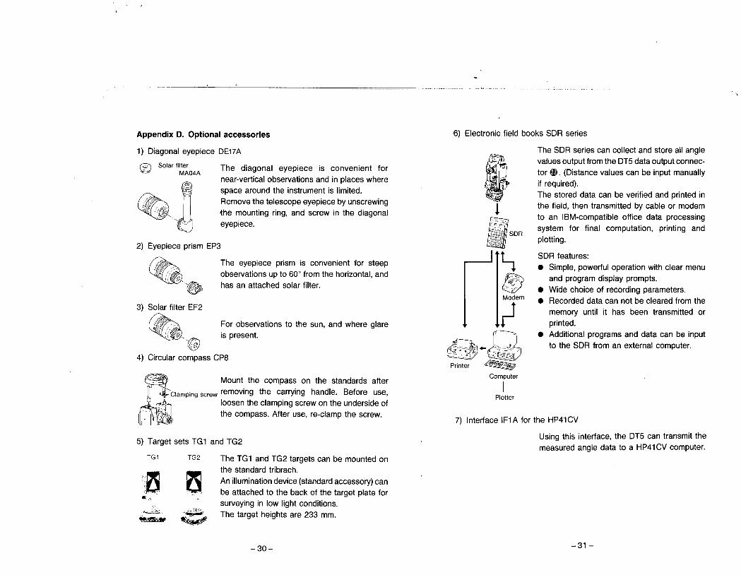
Appendix D. Optional accessories
1) Diagonal eyepiece DE17A
(ô Solar filter The diagonal eyepiece is convenient for~ MA04Anear-vertical observations and in places wherespace around the instrument is limited.Remove the telescope eyepiece by unscrewingthe mounting ring, and screw in the diagonaleyepiece.
.~2) Eyepiece prism EP3
6~'.3) Solar filter EF2
~~../;-',I Il;/
:i 6,~4) Circular compass CP8
The eyepiece prism is convenient for steepobservations up to 60° from the horizontal, andhas an attached solar filter.
For observations to the sun, and where glareis present.
i,~-t Mount the compass on the standards after
Clamping screw removing the carrying handle. Before use,........ on........... loosen the clamping screw on the underside of
.' r ~,.~ , the compass. After use, re-clamp the screw.i i'I "
TG1
5) Target sets TG1 and TG2
TG2 The TG1 and TG2 targets can be mounted onthe standard tribrach.An illumination device (standard accessory) canbe attached to the back of the target plate forsurveying in low light conditions.The target heights are 233 mm.
:~~
.,'~~ ',i~J?'~-30-
6) Electronic field books SDR series
The SDR series can collect and store all anglevalues output from the DT5 data output connec-tor ~. (Distance values can be input manually
if required).The stored data can be verified and printed inthe field, then transmitted by cable or modemto an IBM-compatible office data processing
system for final computation, printing and
plotting.
Ie'
, :-,!
i-tfModem
l-~~~Print~r ~
Computer
I
Plotter
SDR
SDR features:. Simple, powerful operation with clear menu
and program display prompts.. Wide choice of recording parameters.
. Recorded data can not be cleared from the
memory until it has been transmitted orprinted.
. Additional programs and data can be input
to the SDR from an external computer.
7) Interface IF1 A for the HP41 CV
Using this interface, the DT5 can transmit themeasured angle data to a HP41 CV computer.
-31 -

SPECIFICATIONS
TelescopeLength:Aperture:Magnification:Image:Resolving power:
Field of view:
Minimum focus:Stadia ratio:Additve constant:Reticle illumination:
Angle measurementHorizontal and VerticalCircles type:
Angle units:
Minimum display:Accuracy:
Measuring time:Display range:
Horizontal angle:
Vertical angle:
165mm
45mm30X
Erect3"
l' 30' (26m/1000m)0.9m (3ft)100
oProvided
Incremental with 0 index
(0 index for vertical circle only)Degree/gon/ mil
(Selectable with internal switch)5"(0.001 gon/0.02mil)Standard deviation of mean ofmeasurement taken in positions I and Ii
(DIN 18723)5" (0.0015gon/0.02mil)Less than 0.5 sec
0' 00' 00" to 359' 59' 55"
(0.000 to 399.999gon/0.00 to 6399.98mil)0' 00' 00" to 359' 59' 55"
(0.000 to 399.999gon/0.00 to 6399.98mil)/-90' 00' 00" to 90' 00' 00"
(0.000 to 100.000gon/0.00 to 1600.00mil)
(-999.909 to 999.909%)
-32-
Measuring mode:
Horizontal angle:
Vertical angle:
Power supplyPower source:
Working duration:
GeneralDisplay:
Sensitivity of levels:
Optical plum met:
Self-diagnostic function:Power saving cut off:
Audio device:Data output:Operating temperature:Instrument height:Size:
''"
Right/Left/Hold
(Selectable with key board)
Zenith 0" (Ogon/Omil)/Horizontal 0'
(Ogon/Omil)/Horizontal O:: 90'
(O:: 100gon/0:: 1600mil)(Selectable with internal switch)Slope in % (Selectable with key board)
Detachable battery BDC21 (6VDC)
(Alkaline batteries LR6, R6PX4)About 15 hours
(at 25'c/77'F, when using LR6)
DT5/DT5S:LcD double 8-digit on eachface
DT5A/DT5AS:LcD double 8-digit on oneface
With illuminationPlate levels:40''/2mm
Circular level:10'/2mm
Image:ErectMagnification: 3XMinimum focus:1.0m (3ft)Provided30 minutes after last key operation
(ON/OFF with internal switch)ProvidedAsynchronous serial, RS-232C compatible-20 to 50'c (-4 to 122'F)
230mm (0.7ft) (187mm from tribrach dish)150 (W) x 165 (D) X 335 (H) mm
(5.9 x6.5 X13.2 inch)(including handle and battery)
-33-

Weight: DT5/DT5A:4.6kg (10.1Ibs)
DT5S/DT5AS:4.7kg (10.3 Ibs)
(including handle and battery)DT5/DT5A: Detachable typeDT5S/DT5AS:Shifting type
Tribrach:
-34-
...
STANDARD EQUIPMENT
Layout Plan
CI CI
Q?
~~Q)
CD DT5/DT5S/DT5A/DT5AS main unit .1æ Battety (BDC21) . . . . . . . . . . . . . . . .1
(inCluding R6PX4)CI Vinyl cover. . . . . . . . . . . . . . . . . . . .1ø Tubular compass (CP7) . . . . . . . . . .1CI Adjusting pins. . . . . . . . . . . . . . . . .2CI Screwdriver...................1(j Brush"......................1
-35-
"
(Û
CI Cleaning cloth . . . . . . .1CI Lens hood. . . . . . . . . . .1QQ Lens cap. . . . . . . . . . . .1Qj Plumb bob. . . . . . . . . . .1QP Operator's manuaL. . . . .1(j Carrying case (SE30). . .1
Shoulder strap. . . . . . . . . . .1

, ,
"--
MAINTENANCE
a) Wipe off any moisture if the instrument gets wet during operation.
b) Always clean the instrument before returning it to its case. The lensrequires special care. Dust it off with the lens brush first, to removeminute particles. Then, after providing a little condensation bybreathing on the lens, wipe it with a soft, clean cloth or lens tissue.When cleaning the display, keyboard and carrying case, never useany organic solvent (eg. thinners).
c) Store the instrument in a dry room where the temperature remainsfairly constant.
d) Check the tripod for loose fitting and loose screws.
REGULATIONS
Radio Frequency Interference
The specifications and general appearance of the instrument may bealtered at any time and may differ from those appearing in catal~guesand the operator's manuaL.
WARNING:Changes or modifications to this unit not expresslyapproved by the party responsible for compliance could void theuser's authority to operate the equipment.
NOTE:This equipment has been tested and found to comply withthe limits for a Class A digital device pursuant to Part 15 of theFCC Rules.These limits are designed to provide reasonable protec-tion against harmful interference when the equipment is operatedin a commercial environment. This equipment generates, uses, andcan radiate radio frequency energy and, if not installed and usedin accordance with the instruction manual, may cause harmfulinterference to radio communications. Operation of this equipmentin a residential area is likely to cause harmful interference in whichcase the user will be required to correct the interference at hisown expense.
Notice for CanadaThis Class A digital apparatus meets all requirements of CanadianInterference-Causing Equipment Regulations.Cet apparareil numérique de la Class A respecte toutes les exigencesdu Réglement sur Ie matériel brouilleur du Canada.
-36- -37-

CE Conformity Declaration
CE Conformity Declarationin accordance with EMC Directive 89/336ÆEC of the European Community
We herewith declare that the undennentIoned instrument, in view of its design and typeof construction, fully complies with the relevant basic radio irtenerence requirementsof the EMC Directive.
Should the instrument be modified without agreement, this declaration becomes invalid.
Instrument Descrption: Digital Theodolite (Surveying Instrument)
Model Name : DTS, DTSS, DTSA, DTSAS
Relevant EC Directive: EMC Directive (89/336/EEC)Version: 91163/EEC, 92/3!/EEC, 93/68/EEC
AppliedHarmonized Standard: EM! : ENS008!-! 1992
ENSS022 1994,' GlassBEMS: ENSOO82-2 1995
ENVSO!40 1995ENVS0204 1995EN6!OOO-4-2 1995
SOKKIA B. V.Inds1riaterrin 09 VaartDamlulseg 1NL-1332 EA Almer.
Date: uj:lu~!?'c~..- 7'Finn: uu...sOKK):'v...
Address:. ......ln.~.t1.sr.n-tttrr~.i.n.. 'pt-..Y~.¡~!.k.P~~h.ll~~tg.. l.I..Nk l-~~7.. E,A. .Al~~r~....
Representative's Signature: ~ 1J~Name of RepresentativeRepresentative's position
Stephen Blailee
European vice President
-38-
-",1-1, TOMIGAYA 1-CHOME, SHIBUYA-KU, TOKYO, 151 JAPANPHONE +81-3-3465-5211 FAX +81-3-3465-5203INTERNATIONAL DEPT PHONE +81-3-3465-5201 FAX +81-3-3465-5202
SOKKIA CORPORATION 9111 Barton, P.O. Box 2934, Overland Park,Kansas, 66201 U.S.A., Phone + 1-913-492-4900 Fax + 1-913-492-0188SOKKIA CENTRAL & SOUTH AMERICA CORPORATION 1200 NW. 78th Avenue, Suite109 Miami, Florida, 33126 U.S.A Phone + 1-305-599-4701 Fax + 1-305-599-4.703SOKKIA INC. 1050 Stacey Court, Mississauga, Ontario, L4W 2X8 Canada,Phone + 1-905-238-581 0 Fax + 1-905-238-9383AGL CORPORATION 2202 Redmond Road, P.O. Box 189, Jacksonville, Arkansas,72078 U.S.A., Phone + 1-501-982-4433 Fax + 1-501-982-0880SOKKIA PTY. LTD. Rydalmere Metro Centre, Unit 29, 38-46 South St,Rydalmere, NSW, 2116 Australia, Phone +61-2-9638-0055 Fax +61-2-9638-3933SOKKIA WESTERN AUSTRALIA PTY. LTD. (Perth) Unit 2/4 Powell St.,Osborn Park, WA 6117 Australia, Phone +61-8-9201-0133 Fax +61-8-9201-0205SOKKIA NEW ZEALAN D 20 Constellation Drive, c.P.O. Box 4464, Mairangi Bay,Auckland, 10 Auckland, New Zealand, Phone + 64-9-479-3064 Fax + 64-9-479-3066SOKKIA B.v Businesspark De Vaart, Damsluisweg 1, 1332 EA Almere, P. O. Box 1292,1300 BG Almere, The Netherlands, Phone +31-36-53.22.880 Fax +31-36-53.26.241SOKKIA LTD, Datum House, Electra Way, Crewe Business Park, Crewe, Cheshire, CW1 1 ZTUnited Kingdom, Phone +44-1270-25.05.25 Fax +44-1270-25.05.33
SOKKIA B.V. Niederlassung Deutschland An derWachsfabrik 25, 50996 Köln(Rodenkirchen), Germany, Phone +49-2236-6.40.58 Fax +64-2236-6.26.75BLiNKEN A.S. Postboks 122,Østkilen 4, N-1620 Gressvik, Norway,Phone +47-69-32,90.11 Fax +47-69-32.61.21
SOKKIA spo!. s.r.o. Pacovska 31, 14000 Praha, 4 Czech Republic,Phone +42-2-61211372 Fax +42-2-61211194SOKKIA SA 12, Avenue Gabriel Peri, 78360 Montesson, France,Phone + 33-1-30.53.09.73 Fax + 33-1-39.76.63.15SOKKIA S.R.L. Via Aiserio 22, 20159 Milano, Italy,Phone +39-2-66.803,803 Fax +39-2-66.803.804SOKKIA N.v./SA Sphere Businesspark, Doornveld 1-1 A B-1731 Zellik(Brussels), Belgium, Phone +32-2-466.82.30 Fax +32-2-466.83.00SOKKIA VERTRIEBS GmbH Ottakringerstraße 54/4,2 A-1170 Wien, Austria,Phone +43-1-4025.9020 Fax +43-1-4025.9019SOKKIA KFT. Legszesgyar U. 17.3.em, 7622 Pees, Hungary,Phone +36-72-324.636 Fax +36-72-324.636SOKKIA KOREACO.,LTD. Rm. 401, Kwan Seo Bldg, 561-20 Sinsa-dong,Kangnam. ku, Seoul, Republic of Korea, Phone + 82-2-514-0491 Fax + 82-2-514-0495SOKK.IA SINGAPORE PTE. LTD. 401 Commonwealth Drive, #06-01 Haw ParTechnocentre, 149598 Singapore, Phone +65-479-3966 Fax +65-479-4966SOKKIA (M) SDN. BHD. NO.88 Jalan SS 24/2 Taman Megah, 47301 Petaling Jaya,Selangor Darul Ehsan, Malaysia, Phone + 60-3-7052197 Fax + 60-3-7054069SOKKIA HONG KONG CO.,LTD. Rm. 1406 Shatin Galleria, 18-24 Shan Mei Street,Fo Tan, New Territories, Hong Kong, Phone +852-2-6910280 Fax +852-2-6930543SOKKIA PAKISTAN (pyr) LTD. MUGHALlYA Centre, Allama RashidTurabi Rd., Blk"N"North Nazimabad, Karachi 74700 Pakistan,Phone + 92-21-6644824 Fax + 92-21-6645445SOKKIA GULF P.O. Box 4801, Dubai, UAE.,Phone +971-4-690965 Fax +971-4-694487SOKKIA RSA PTY, LTD. P.O. Box 7998, Hennopsmeer, 0046 Republic of South Africa,Phone +27-12-663-7999 Fax +27-12-663-4039SOKKIA CO.,LTD. SHANGHAI REP. Office 4F Bldg. No.1, 1299 Xinjinqiao Road,Pudong Jinqiao Export Processing Zone, Shanghai, 201206 People's Republic of China,Phone +86-21-58345644 Fax +86-21-58348092