Electronic Diagrams Chapter 18. 2 Technical Drawing 13 th Edition Giesecke, Mitchell, Spencer, Hill...
27
Electronic Diagrams Chapter 18
-
Upload
kathlyn-ross -
Category
Documents
-
view
232 -
download
7
Transcript of Electronic Diagrams Chapter 18. 2 Technical Drawing 13 th Edition Giesecke, Mitchell, Spencer, Hill...

Electronic Diagrams
Chapter 18

2Technical Drawing 13th EditionGiesecke, Mitchell, Spencer, Hill Dygdon, Novak, Lockhart
© 2009 Pearson Education, Upper Saddle River, NJ 07458.
All Rights Reserved.
Objectives
• Identify common component symbols on an electronic schematic diagram
• Draw a schematic diagram using standardized symbols
• Draw connecting and crossover paths

3Technical Drawing 13th EditionGiesecke, Mitchell, Spencer, Hill Dygdon, Novak, Lockhart
© 2009 Pearson Education, Upper Saddle River, NJ 07458.
All Rights Reserved.
Objectives (cont.)
• Identify interrupted and uninterrupted lines
• Designate terminals and numerical values of components

4Technical Drawing 13th EditionGiesecke, Mitchell, Spencer, Hill Dygdon, Novak, Lockhart
© 2009 Pearson Education, Upper Saddle River, NJ 07458.
All Rights Reserved.
Types of Electronic Diagrams• The following are types of
diagrams defined in ANSI Y114.24-1999:• Functional block diagram• Single line diagram• Schematic diagram or circuit diagram• Connection or wiring diagram• Interconnection diagram

5Technical Drawing 13th EditionGiesecke, Mitchell, Spencer, Hill Dygdon, Novak, Lockhart
© 2009 Pearson Education, Upper Saddle River, NJ 07458.
All Rights Reserved.
Functional Block Diagram
6Technical Drawing 13th EditionGiesecke, Mitchell, Spencer, Hill Dygdon, Novak, Lockhart
© 2009 Pearson Education, Upper Saddle River, NJ 07458.
All Rights Reserved.
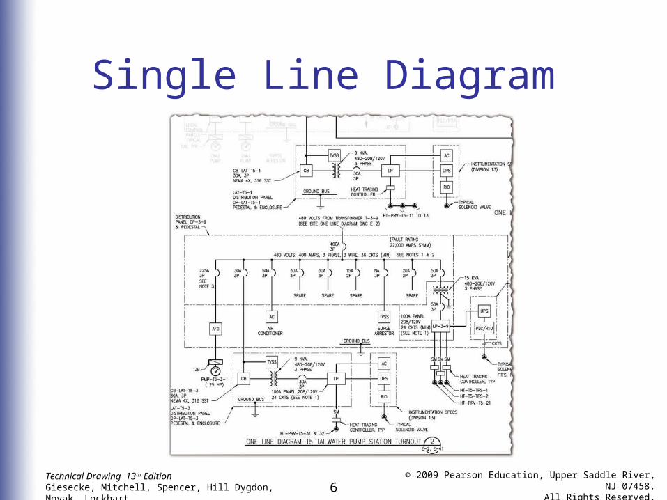
Single Line Diagram

7Technical Drawing 13th EditionGiesecke, Mitchell, Spencer, Hill Dygdon, Novak, Lockhart
© 2009 Pearson Education, Upper Saddle River, NJ 07458.
All Rights Reserved.
Schematic Diagram

8Technical Drawing 13th EditionGiesecke, Mitchell, Spencer, Hill Dygdon, Novak, Lockhart
© 2009 Pearson Education, Upper Saddle River, NJ 07458.
All Rights Reserved.
Connection Diagram

9Technical Drawing 13th EditionGiesecke, Mitchell, Spencer, Hill Dygdon, Novak, Lockhart
© 2009 Pearson Education, Upper Saddle River, NJ 07458.
All Rights Reserved.
Standard Symbols
• Symbols should conform to an internationally or nationally approved standard
• Symbols should be drawn roughly 1.5 times the size of those shown in the IEEE 315A standard

10Technical Drawing 13th EditionGiesecke, Mitchell, Spencer, Hill Dygdon, Novak, Lockhart
© 2009 Pearson Education, Upper Saddle River, NJ 07458.
All Rights Reserved.
Standard Symbols
• Switches and relays should be shown in the “normal” position with no operating force or applied energy

11Technical Drawing 13th EditionGiesecke, Mitchell, Spencer, Hill Dygdon, Novak, Lockhart
© 2009 Pearson Education, Upper Saddle River, NJ 07458.
All Rights Reserved.
Abbreviations
• Abbreviations on electrical diagrams should conform to ANSI/ASME Y1.1

12Technical Drawing 13th EditionGiesecke, Mitchell, Spencer, Hill Dygdon, Novak, Lockhart
© 2009 Pearson Education, Upper Saddle River, NJ 07458.
All Rights Reserved.
Grouping Parts
• Indicate grouped components using dashed lines to enclose them in a “box”

13Technical Drawing 13th EditionGiesecke, Mitchell, Spencer, Hill Dygdon, Novak, Lockhart
© 2009 Pearson Education, Upper Saddle River, NJ 07458.
All Rights Reserved.
Arrangement of Symbols
• Arrange the various parts and symbols to balance blank areas and lines
• Provide sufficient blank spaces adjacent to symbols to allow for reference designations and notes

14Technical Drawing 13th EditionGiesecke, Mitchell, Spencer, Hill Dygdon, Novak, Lockhart
© 2009 Pearson Education, Upper Saddle River, NJ 07458.
All Rights Reserved.
Signal Path
• Arrange schematic and single-line diagrams so that signal or transmission path from input to output proceeds from left to right and from top to bottom when possible

15Technical Drawing 13th EditionGiesecke, Mitchell, Spencer, Hill Dygdon, Novak, Lockhart
© 2009 Pearson Education, Upper Saddle River, NJ 07458.
All Rights Reserved.
Connections and Crossovers• Connecting lines for conductors
are typically drawn horizontally or vertically to minimize bends and crossovers
16Technical Drawing 13th EditionGiesecke, Mitchell, Spencer, Hill Dygdon, Novak, Lockhart
© 2009 Pearson Education, Upper Saddle River, NJ 07458.
All Rights Reserved.
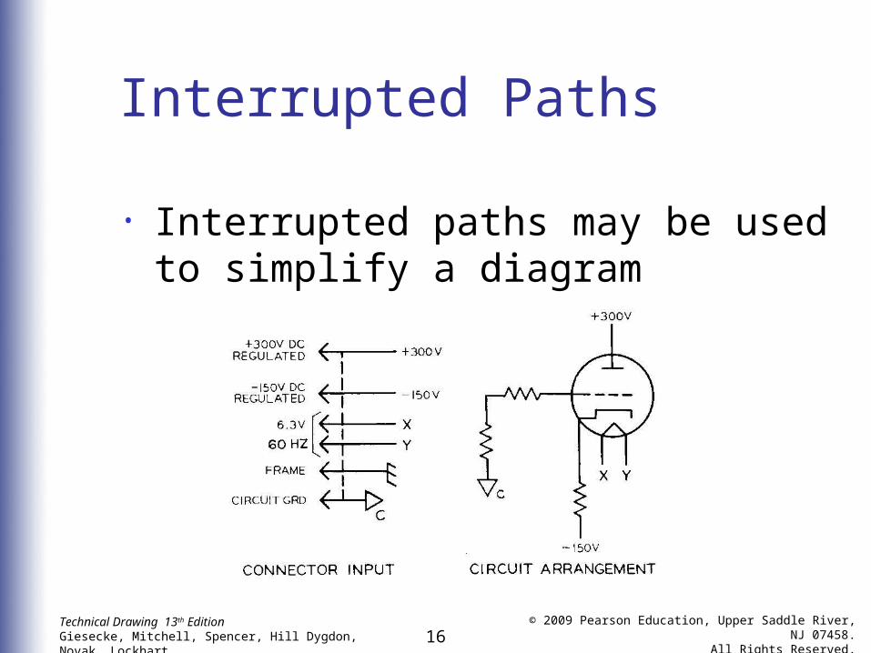
Interrupted Paths
• Interrupted paths may be used to simplify a diagram

17Technical Drawing 13th EditionGiesecke, Mitchell, Spencer, Hill Dygdon, Novak, Lockhart
© 2009 Pearson Education, Upper Saddle River, NJ 07458.
All Rights Reserved.
Terminals
• Terminal circles need not be shown unless they are needed for clarification

18Technical Drawing 13th EditionGiesecke, Mitchell, Spencer, Hill Dygdon, Novak, Lockhart
© 2009 Pearson Education, Upper Saddle River, NJ 07458.
All Rights Reserved.
Color Coding
• Terminals or leads are frequently identified by colors or symbols which should be indicated on the diagram

19Technical Drawing 13th EditionGiesecke, Mitchell, Spencer, Hill Dygdon, Novak, Lockhart
© 2009 Pearson Education, Upper Saddle River, NJ 07458.
All Rights Reserved.
Division of Parts
• For clarity, draw sections of multi-element parts separately in a schematic
• Indicate subdivisions with suffix letters

20Technical Drawing 13th EditionGiesecke, Mitchell, Spencer, Hill Dygdon, Novak, Lockhart
© 2009 Pearson Education, Upper Saddle River, NJ 07458.
All Rights Reserved.
Electron Tube Pin Identification• Electron tubes are generally not
used in new designs but are still common in high-power amplifiers

21Technical Drawing 13th EditionGiesecke, Mitchell, Spencer, Hill Dygdon, Novak, Lockhart
© 2009 Pearson Education, Upper Saddle River, NJ 07458.
All Rights Reserved.
Reference Designations
• It is essential to identify each separately replaceable part with appropriate combinations of letters and numbers
• Portions not separately replaceable are frequently identified

22Technical Drawing 13th EditionGiesecke, Mitchell, Spencer, Hill Dygdon, Novak, Lockhart
© 2009 Pearson Education, Upper Saddle River, NJ 07458.
All Rights Reserved.
Numerical Values
• Along with reference designations, the following numerical values should also be shown:• Resistance• Capacitance• Inductance

23Technical Drawing 13th EditionGiesecke, Mitchell, Spencer, Hill Dygdon, Novak, Lockhart
© 2009 Pearson Education, Upper Saddle River, NJ 07458.
All Rights Reserved.
Other Information
• The following information may also be included on schematic diagrams:• Functional identification• DC resistance of transformer windings
or coils• Critical input or output impedance
values• Voltage or current wave shapes at
selected points

24Technical Drawing 13th EditionGiesecke, Mitchell, Spencer, Hill Dygdon, Novak, Lockhart
© 2009 Pearson Education, Upper Saddle River, NJ 07458.
All Rights Reserved.
Other Information (cont.)
• Wiring requirements for critical ground points, shielding, pairing, etc.
• Power or voltage ratings of parts• Identification of operational controls
or circuit functions

25Technical Drawing 13th EditionGiesecke, Mitchell, Spencer, Hill Dygdon, Novak, Lockhart
© 2009 Pearson Education, Upper Saddle River, NJ 07458.
All Rights Reserved.
Integrated Circuits
• An integrated circuit is a semiconductor wafer or chip

26Technical Drawing 13th EditionGiesecke, Mitchell, Spencer, Hill Dygdon, Novak, Lockhart
© 2009 Pearson Education, Upper Saddle River, NJ 07458.
All Rights Reserved.
Printed Circuits
• Printed circuit boards are widely used and replace hand-wiring methods

27Technical Drawing 13th EditionGiesecke, Mitchell, Spencer, Hill Dygdon, Novak, Lockhart
© 2009 Pearson Education, Upper Saddle River, NJ 07458.
All Rights Reserved.
Computer Graphics
• CAD greatly simplifies the process of producing printed circuit artwork
• CAD component layout programs allow you to create the best possible parts placement