Electronic Circuits for Electrophysiologistsdaw/assets/circuits.pdf · Electronic Circuits for...
13
Electronic Circuits for Electrophysiologists Adapted by Daniel A. Wagenaar From an original by Kevin Briggman* In this tutorial, we will start by building some very simple electronic circuits, and end up with three circuits that are of fundamental importance to electrophysiology. ose are: 1) Ion channels in a membrane: 2) A neuron with an intracellular electrode: (is is the basis of a neuron’s resting potential.) 3) A passive neuronal process: You will be building these circuits using resistors, capacitors, and baeries, using a “breadboard” to connect them. * Original text by K. Briggman; edited by B. V. Atallah, W. B. Kristan, D. A. Wagenaar, and A. Stowasser
Transcript of Electronic Circuits for Electrophysiologistsdaw/assets/circuits.pdf · Electronic Circuits for...

Electronic Circuits for Electrophysiologists
Adapted by Daniel A. Wagenaar
From an original by Kevin Briggman*
In this tutorial, we will start by building some very simple electronic circuits, and end up with three circuits that are of fundamental importance to electrophysiology. Those are:
1) Ion channels in a membrane: 2) A neuron with an intracellular electrode:
(This is the basis of a neuron’s resting potential.)
3) A passive neuronal process:
You will be building these circuits using resistors, capacitors, and batteries, using a “breadboard” to connect them.
* Original text by K. Briggman; edited by B. V. Atallah, W. B. Kristan, D. A. Wagenaar, and A. Stowasser

At your rig, you have a plastic bag containing:
3 2.2 MΩ resistors 3 0.01 µF capacitors3 1 MΩ resistors 3 470 pF capacitors3 100 kΩ resistors 2 10 pF capacitors
3 47 kΩ resistors 2 AA (1.5V) batteries and holders3 1.5 kΩ resistors 1 breadboard1 100 kΩ potentiometer many wires
Your breadboard is diagrammed below. It provides a convenient way to build temporary circuits. The resistor and capacitor wires, as well as the jumper wires, fit snugly into the holes and make contact with the metal lining the holes. Some holes are connected together under the board; these connections are indicated by the lines connecting dots in the diagram. Putting two wires into connected holes provide an electrical contact between them. Think of these as temporary solder.
Before starting, there are two basic bits of physics we should recall. These are:
A. Resistors and Ohm’s law
A resistor converts electrical energy into heat when current flows through it. A current (I ) flowing through a resistance (R ) creates a voltage drop (V ) across that resistor, described by Ohm’s law:
V = I R
In words, the voltage across a resistor is proportional to the current, and resistance is the proportionality constant. The units are volts (V), amps (A), and ohms (Ω). Some useful facts:
• 1 ampere flowing through a 1 Ohm resistor produces 1 volt across the resistor. • In electrophysiology, we usually work with:
millivolts (mV) = 10-3 V;nanoamps (nA) = 10-9 A;megohms (MΩ) = 106 Ω.
2

B. Kirchoff’s circuit laws
Kirchoff’s laws state two relatively intuitive facts:1. The voltage at a given point in a circuit is uniquely defined. From this simple statement follow
two important rules:i. If there are two (or more) paths to go from a point A in a circuit to a point B, the voltage
drop along each of those paths is the same.ii. In particular, the voltage drops around a closed loop must sum to zero. (Think about that
one for a moment.)2. Current cannot disappear into thin air, nor appear from it. From this it follows that the sum of
all currents going into a point must equal the sum of all currents going out of it.
For instance, in the circuit to the right:: i1 = i2 + i3.
Electrophysiological circuit #1: Basis of the resting potential
Every cell—neurons included—has different concentrations of ions on either side of its outer membrane that set up a relatively stable “resting potential”. The concentration gradients of these ions can be modeled as batteries. The voltage and orientation of these batteries depend on the amplitude and direction of the concentration gradient, the charge on the ions, and the conductance (1/R ) of the channels specific for each ion. To get a feeling for how this can occurs electrically, you will first need to understand some properties of resistors arranged in series and in parallel.
Reading the value of a resistorMost resistors have four color bands around them. The first three encodethe resistance; the fourth encodes precision. The chart on the right indicates the color code. The convention is: XY × 10Z.
For example:Yellow/Green/Red is 45 x 102 Ω = 4500 Ω = 4.5 kΩ Brown/Black/Blue is 10 x 106 Ω = 10,000,000 Ω = 10 MΩ.
The most common precision colors is gold (±5%).
You have: Br/Gr/Red = 1.5 kΩRed/Red/Gr = 2.2 MΩBr/Bl/Gr = 1.0 MΩBr/Bl/Yel = 100 kΩ
3
X
Y Precision
Z
0 - Black1 - Brown2 - Red3 - Orange4 - Yellow5 - Green6 - Blue7 - Violet8 - Gray9 - White

1a. Resistor series circuit
Connect a battery in series with two 100 kΩ resistors in series. (In electronics, “in series” means head-to-tail.) Because a battery is a constant voltage source, the total voltage across the resistors should be the total voltage of the battery (Kirchoff’s first law). We’ll measure this voltage, to make sure.
A convenient device to measure voltage is a Voltmeter, which might cost $19.95 at Radio Shack*. Instead, you are going to use a Axon Instruments device to measure the voltage and digitize it, at a cost about 200x as much. (We are not spendthrift; we want to learn how to use the equipment.) You can thenuse the “ClampEx” program to display the results on your computer screen.
Use the protocol “bread_battery.pro” to record from Analog Input 7, and connect the ground pin from a BNC cable connected to this channel to the circuit ground, using a banana adapter and alligator clips. Connect the “hot” pin across the two resistors, i.e., to the end of the resistor farthest from ground. Now measure the voltage across just one of the resistors (i.e., connect the “hot” lead to the point between the resistors). How do the voltages compare?
Based on your measurements, do you believe that Rtotal = R1 + R2 for two resistors in series? If you do, calculate the current, I, through the resistors. If you don’t, reconsider.
* I’m actually not sure where to buy such things except online now.
4
Circuit 1
BNC cables, banana adapters (two styles, arrows mark side to be used for ground), and alligator cables

1b. Resistor parallel circuit
Now put a 100 kΩ resistor in parallel with one of the resistors. (In electronics, “in parallel” means side-by-side.)
Repeat the measurements, measuring the voltage across the whole circuit, then across just the two resistors in parallel. Are they the same as with just the two resistors in series? Explain.
Calculate I through each resistor, assuming that 1/Rtotal = 1/R1 + 1/R2
1c. Relating these measurements to the resting potential.
Here’s a more complete circuit model of a passive membrane:
The balance between the concentration gradients (represented by the batteries) and conductances (represented by the resistors) is what leads to a resting membrane potential.
i. Build a similar circuit:
5
Circuit 3
Circuit 2
Notice that the battery on the left is inverted (has the opposite polarity) relative to the one on the right.
(We've left out the capacitorfor simplicity. It won't affectthe results here.)

Q1: If you measured the voltage between A and B, what would you get?Q2: Does this mean that no current is flowing?(Answers on next page; think first.)
How then can we get a non-zero resting membrane potential? There are two ways: We could either have non-equal batteries (i.e. different concentration gradients) or non-equal conductances (i.e. differentpermeabilities for different ions). In the next exercise, you’ll test the effect of changing conductances.
ii. Build this circuit on your breadboard:
You can ground either A or B. See what difference it makes.
What voltage are you reading between A and B? You can change the resistance of the potentiometer by turning the round bar sticking out of it. Watch what happens as you change the resistance. Can you get it to cancel out the other branch exactly so that the voltage between A and B becomes zero again?
Bonus question: What resistance do you need to set the pot to in order to get a resting membrane potential of –50 mV? (Hint: figure out how much current needs to flow through the left branch to get a potential of –50 mV and then how much resistance you need on the right to get this current.)
Electrophysiological circuit #2: A neuron with an intracellular electrode
So far, all the measurements have ignored how fast the voltage changes take place. Indeed, if membranes and electrodes were purely resistors, all voltage changes would take place instantaneously. In fact, the changes always have a delay because the membranes also have properties of capacitors.
What is a capacitor? Any two conductors separated by an insulator form a capacitor. A lipid bilayer, for instance, is a good capacitor. In your bag you have several capacitors made in a factory. Capacitors accumulate electric charge on the insulator. The accumulated charge creates an electric field between the conductors and stores electrical energy.
6
Circuit 4
How to tell the capacitance of a capacitor Some capacitors have something like 0.1 M printed on them. This means 0.1 µF (the M is for micro; guess it’s easier to print than µ). Smaller ones have 3 digits on them, something like 153. This means 15 x 103 pF, i.e., 15000 pF or 15 nF.
You have: 471J = 47 x 101 pF = 470 pF (“J” refers to the material; ignore it)103 E5M = 10 x 103 pF = 0.01 µF (“E5M”, too, is irrelevant)10 = 10 pF

Circuit
componentSymbol
A currentstep (I) like
this…
… producesthis voltage
(V) response.Equation
Resistor
V = I RR is measured in
ohms (Ω)
Capacitor
I = C dV/dtC is measured in
farads (F)
Circuits with resistors and capacitors
When you connect a resistor in parallel with a capacitor, the result is called a parallel RC circuit:
The exponential increase in the voltage measurement up to the steady state is called the RC time constant (). Why does this happen? When you inject current into this circuit, it can flow through either the resistor or the capacitor. At first, the capacitor is not charged, so it is easy to push charge intoit, and most of the current goes into the capacitor. As the capacitor gets charged more and more, the charges already there resist the arrival of new charge more and more strongly. After a while, the capacitor is saturated. From that moment on, all current flows through the resistor. (Bigger capacitors can store more charge: Q = CV. At steady state, V = IR.)
Why is the rise in voltage exponential? You can solve the equations for a resistor and capacitor in parallel to see why. Intuitively, it’s because the rate of addition of charge depends on the amount of charge already stored; this kind of physical process always produces an exponential change over time. is the time the voltage takes to reach 1 - e-1 (about 2/3) of its steady-state level. Also, equals the resistance (in ohms) times the capacitance (in farads). In units: 1 second = 1 ohm x 1 farad.
The following exercises are intended to help you understand the effects of capacitance on membrane properties.
2a. Insert a 1 MΩ resistor on the breadboard as in circuit 5 below. You’re going to use the computer to deliver the square-wave pulses of current. (This is a source of constant current: over a wide range, it will provide the indicated current no matter how big—or small--the resistor is. This procedure is often calledcurrent clamp.) You’ll be using the left-hand (“green”) head stage from the computer to deliver 10 nA of
7
Answers to questions on p. 6:A1: Since there’s an equal and opposite voltage gain and voltage drop going in each direction, you should measure zero resting membrane potential. A2: It does not. Current is flowing, but the voltage between A and B is zero anyway. Why?
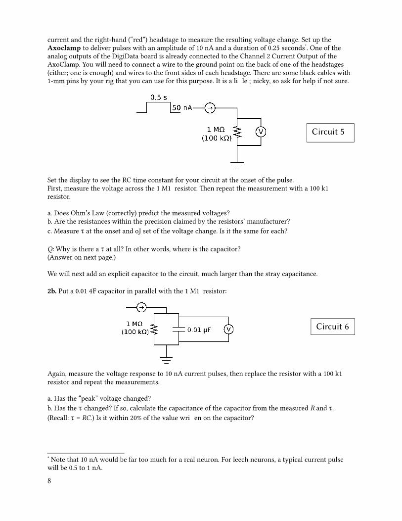
current and the right-hand (“red”) headstage to measure the resulting voltage change. Set up the Axoclamp to deliver pulses with an amplitude of 10 nA and a duration of 0.25 seconds*. One of the analog outputs of the DigiData board is already connected to the Channel 2 Current Output of the AxoClamp. You will need to connect a wire to the ground point on the back of one of the headstages (either; one is enough) and wires to the front sides of each headstage. There are some black cables with 1-mm pins by your rig that you can use for this purpose. It is a little finicky, so ask for help if not sure.
Set the display to see the RC time constant for your circuit at the onset of the pulse. First, measure the voltage across the 1 MΩ resistor. Then repeat the measurement with a 100 kΩ resistor.
a. Does Ohm’s Law (correctly) predict the measured voltages?b. Are the resistances within the precision claimed by the resistors’ manufacturer?c. Measure at the onset and offset of the voltage change. Is it the same for each?
Q: Why is there a at all? In other words, where is the capacitor?(Answer on next page.)
We will next add an explicit capacitor to the circuit, much larger than the stray capacitance.
2b. Put a 0.01 µF capacitor in parallel with the 1 MΩ resistor:
Again, measure the voltage response to 10 nA current pulses, then replace the resistor with a 100 kΩ resistor and repeat the measurements.
a. Has the “peak” voltage changed?b. Has the changed? If so, calculate the capacitance of the capacitor from the measured R and . (Recall: = RC.) Is it within 20% of the value written on the capacitor?
* Note that 10 nA would be far too much for a real neuron. For leech neurons, a typical current pulse will be 0.5 to 1 nA.
8
Circuit 5
Circuit 6

[Logically, these two exercises fit in here, but they are not as crucial as those that follow. You should do those first, then return to this page if you have time.]
2c. What happens to the of a parallel RC circuit when there are two 1 MΩ resistors in parallel? Check it out, using circuit 7.
2d. How about capacitors in parallel and series? Arrange a 1 MΩ resistor in parallel with two capacitors, either in series (circuit 8) or in parallel (circuit 9) and calculate the capacitance from measurements of . Do parallel and series capacitors sum in the same way as resistors? Can you explain why (not)?
Recording from a neuron with an intracellular (“sharp”) microelectrode
Now we’re going to focus on three parallel and series RC circuits that you’ll encounter once you start recording from real neurons. First is the glass microelectrode you’ll use to impale cells.
2e. The microelectrode
9
The tip of the electrode acts like a resistor.
The walls of the electrode form a capacitor.
You fill the electrode with an electrolytic solution and pass current with a chlorided silver wire.
The cell membrane islike a parallel RC circuit, see below.
Circuit 7
Circuit 9
Circuit 8
Answer to question on p. 8: There is always some “stray” capacitance in a circuit. If you calculate C from and R you will probably find C is about 10 or 20 pF.
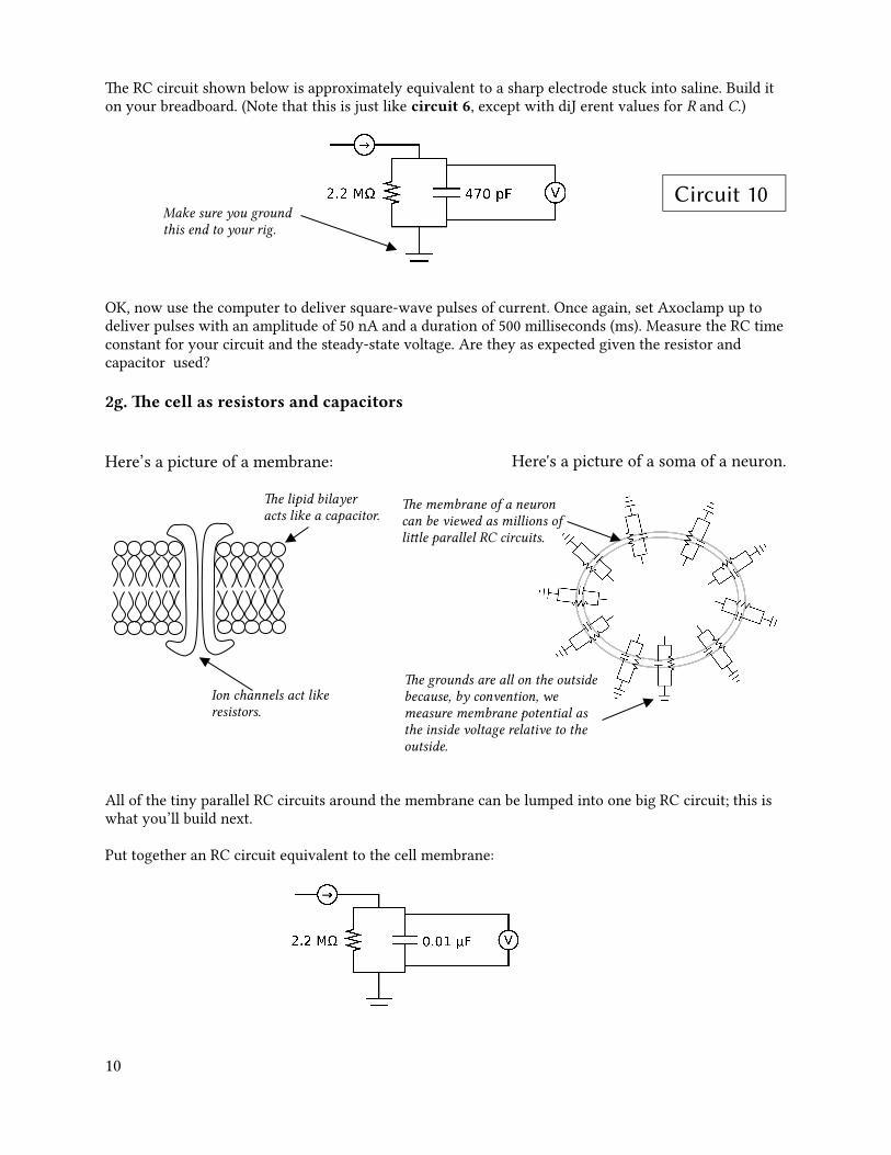
The RC circuit shown below is approximately equivalent to a sharp electrode stuck into saline. Build it on your breadboard. (Note that this is just like circuit 6, except with different values for R and C.)
OK, now use the computer to deliver square-wave pulses of current. Once again, set Axoclamp up to deliver pulses with an amplitude of 50 nA and a duration of 500 milliseconds (ms). Measure the RC timeconstant for your circuit and the steady-state voltage. Are they as expected given the resistor and capacitor used?
2g. The cell as resistors and capacitors
Here’s a picture of a membrane:
All of the tiny parallel RC circuits around the membrane can be lumped into one big RC circuit; this is what you’ll build next.
Put together an RC circuit equivalent to the cell membrane:
10
Make sure you ground this end to your rig.
The lipid bilayer acts like a capacitor.
Ion channels act like resistors.
Circuit 10
Here's a picture of a soma of a neuron.
The grounds are all on the outside because, by convention, we measure membrane potential as the inside voltage relative to the outside.
The membrane of a neuron can be viewed as millions of little parallel RC circuits.

Deliver the same pulses that you used for the electrode circuit. What’s the new time constant? Steady-state voltage? What should they be?
Here’s a biophysics question: What happens to the membrane resistance and capacitance as the diameter of a cell increases? (Hint: how do resistance and capacitance sum in parallel?) What effect would this have on the time constant?
Now we want to figure out what happens when you stick an electrode into a neuron. Here’s a picture ofwhat that looks like:
Build the equivalent electrode-membrane RC circuit:
• Start by drawing the equivalent circuit above and build it on your board using the elements from the other exercises (if you really get stuck the circuit is drawn below—circuit 12).
• Next, inject current pulses just as you did before. This time, though, instead of seeing one time constant, you should now see the two time constants that you already measured—the fast one from the electrode and the slower one from the membrane. Do you see them? How about the steady-state voltage change? Same? Bigger? Smaller? Why?
When you record from real neurons, you will want to cancel out the resistance of the electrode (sometimes called the “series resistance”). If you use Channel 2 both for injecting current and for measuring voltage, you can do this by adjusting the Bridge balance control on the Axoclamp. Turn up the balance until you see the fast time constant disappear and you’re only left with the slower time constant. (Yes, this is pretty subjective). Canceling out the series resistance like this is sometimes called “balancing the bridge”, because the first circuit used for this purpose was something called a Wheatstone Bridge after the guy who popularized it. (Sir Charles Wheatstone, in the mid 1800s, used it as a way to measure resistances.)
In place of the fast time constant, you’ll now see a capacitative transient, a fast upward or downward blip. These are sometimes called “rabbit ears”. In principle, you can cancel out this transient by tuning the Capacitance compensation. Try it. Did it do anything? It may not be possible to compensate for this much capacitance. In that case, replace the 470 pF capacitor by 10 pF. You may need to increase the sampling rate to be able to see the very fast rabbit ears that result.
The point of this is to show you what to do to get a beautiful recording from a real neuron: First, balance the bridge. Second, adjust the capacitance compensation.
11
Circuit 12 is on the next page. (Don't look unless you get really stuck.)

Electrophysiological circuit #3: Passive properties of a neuronal process
Now that you’re a circuit-building expert, let’s do something a little more complicated. When we measured membrane time constants earlier, we assumed that a neuron was a perfect sphere. This assumption allows us to treat the inside of the cell as though it were isopotential (i.e., the same potential everywhere). A real neuron, however, is much more complex; in particular, it has axons and dendrites. As a signal spreads passively down a dendrite, for example, the signal decreases with distance, for two reasons: 1) the signal leaks out across channels (i.e., the membrane resistance); and 2) there is a resistance along the inside of the dendrite (due to stuff in the cytoplasm). A passive dendrite can be modeled like this:
Build the circuit above, then deliver current pulses into it as you did before. The idea is to inject current into point A, while measuring the voltage at point A, B and C (one at a time). Perform these measurements with three different values (1.5 kΩ, 100 kΩ, and 1MΩ) for R, the axial resistance.
12
Circuit 13
Circuit 12

At each of the three points measure the peak voltage and the time constant of the response. Plot your results below as a function of distance:
Is that what you expected? How does the attenuation of the current pulse relate to the axial resistance?
As an aside, studies have shown that the dendrites of many types of neurons contain active ion channels (i.e. channels that change their conductance when a signal depolarizes or hyperpolarizes them). As a result, real dendrites can exhibit more complex behavior than what you saw here. Still, the RC circuit model is often a reasonable approximation. (Biological question: Why would you want active conductances in dendrites?)
OK, that’s it. Now you’re ready to do real electrophysiology!
— Daniel Wagenaar, Woods Hole, June 2015
13
Steady state voltage
A B C
A B C