ELECTRONCS, VOL. 22, NO. 1, JNE 2018 5 A Study of Inverter ...
ELECTRONICS, VOL. 21, NO. 2, DECEMBER 2017 95
Simulation of a Pick-and-Place Cube Robot by Means of the Simulation Software Kuka Sim Pro
Duško Lukač and Miljana Milić
Abstract — In this work the creation of the program code for industrial robot and the simulation of a robot cell by means of the simulation software KUKA Sim Pro in version 2.2.2, is presented. Simulated and programmed is, in reality existing KUKA-robot cell with industrial robot of the type KR6 R900 sixx (Agilus) with signal connected conveyor belt. The software KUKA Sim Pro is a program for design of 3D-layouts of a plant components including KUKA-robots. On this occasion, any layouts and concept designs can be simulated and be analysed. The used components were taken from the integrated library or were partly newly created. The industrial robot KUKA KR6 R900 sixx counts to the quickest robots of the world. In this work, the simulation of the robot cell and periphery is elaborated, as well as with it, connected practical circumstances and issues with the programming of the abovementioned robot.
Keywords – Industrial Robot, Simulation, KUKA Sim Pro, Pick-and-Place, Cube, Education
Review PaperDOI: 10.7251/ELS1721095L
I. Introduction
Comparing the simulation systems for robots of today with those of the 90s, it can be argued, that compared to the 90s, there are nowadays a lot of useful simulation systems which can be effortlessly used in the industrial practice and education. The rising offer of such simulation systems hangs immediately together up with the development of the IT technology and the computer engineering. As stated in [1], the middle and the end of the 90’s have been marked by the use of the Java based systems. The main improvement of the robot simulation systems, has been caused by the development of the suitable simulation robot libraries, also of the libraries for older industrial robot models [2] which have been already mathematically well modelled in the 60’s. There are many reasons nowadays why to use simulation systems in industrial practice. As stated by [3] by using of simulations wrong decisions can be avoided already in planning stadium and therefore they are sound decisive factor
in the planning process. Furthermore they can save the costs because in the regularly case, the simulation costs are much lower as investment costs or the target cost of the real process. Behind it, simulation leads to a more quick solution than analytic procedures, detailed representation of the existing system can lead to new cognitions and often the simulation technology is generally the only analytical possibility to scrutinize the project, because a real realization of the model would not be possible in practice. All those are factors, which support the idea of the necessity of simulation systems’ usage in the industry but also in the educational practices at school and/or universities. However, the successful use of such systems requires profound knowledge, not only about the simulation software itself, but also about the margin disciplines and branches of learning, which concern the real simulation problem. Especially the “3D fabric simulation is complex and its implementation requires knowledge in different fields” [4, p. 634]. In the following section, it will be, with the help of a practical problem formulation explained, how industrial robot simulation software can be used in the practical case.
II. System Components and Simulation Environment
The choose the suitable simulation software is one of the important decisions in the simulation practice. Different criteria influence this choice. Besides, is to be noted that there are, as a rule, slight decisive differences if the software is seated for industrial purposes or if it used for education purposes. The essential decisive factors for the simulation choice in the educational application are explained in [1]. At the market one can find different robot simulation systems. To find the right one for use requires the knowledge of the technical systems and also the knowledge about the industrial robot market. Some often used simulation application in robotics are presented in the following table:
Table I. Industrial Simulation Systems for Industrial Robots
Name of the application Producer
RoboGuide FANUC K.K.
RobotStudio ABB AG
KUKA Sim KUKA AG
CODESYS 3S-Smart Software Solutions GmbH
It is an interest of the university to educate students in that way that they become prepared for requirements of the industrial
Manuscript received: May 18th, 2017Received in revised form: February 12th, 2018Duško Lukač, Rheinische Fachhochschule Köln gGmbH, University of
Applied Sciences, Vogelsanger Strasse 295, 50825 Köln, Deutschland, e-mail: [email protected]
Miljana Milić, Laboratory for Electronic Design Automation, Faculty of Electronic Engineering, University of Niš, Niš, Serbia, e-mail: [email protected]
ELECTRONICS, VOL. 21, NO. 2, DECEMBER 201796
market. Therefore it is understandable that such robot systems and simulation applications should be used at the university, which are mostly implemented in the industrial companies. Due to those criteria and the vast amount of today’s robot simulation applications today, in the following are briefly introduced four simulation applications, which are shortly mutually evaluated. These above named simulation applications of the companies FANUC K.K., ABB AG, KUKA AG and 3S-Smart-Smart Soft-ware Solutions GmbH are often used in the industrial applications. Furthermore it is to be pointed out that intermutually translation applications exist, as e.g. “SubitoRun”, which enable translation of the application of the one company into other, here of FANUC GUI into KUKA GUI. Such translation modules exist also in the case of KUKA C4 interfaces which are translated into Siemens S7 GUI. Even translation of Siemens TIA portal exist, which is offered by “FTP Robotik” [9]. It indicates the necessity of the development of such specified translation-software market. Accordingly, especially hardware demands and the licensing conditions have to be taking into consideration [1, p. 1013]. Out of the different robot industrial simulation systems available on the market, as e.g. RoboGuide by FANUC or Robot Studio by ABB, the KUKA SIM Pro software has been used in the realization of the project described in this paper. The main reason for it, are the hardware demands, because simulation is applied to the existing industrial robot KUKA KR6 R900 sixx, which is also available in the library of the named simulation platform.
A. KUKA.Sim Pro
KUKA.Sim Pro is a special program for the creation of 3D-layouts of arrangements with KUKA industrial robots. Any layouts and draughts can be simulated and be examined with it. Therefore, the software system is appropriate for engineering or system integrators. The program library is extended compared with the older software versions and it disposes numerous smart components and geometries with own parametric behavior, as e.g. conveyor belts or light barriers. The software offers, also wide-ranging API and COM functionalities which allow the integration of the own plug-ins. An integration of the Python scripts is also pos-sible. Optionally are available possibilities for imports of dif-ferent CAD formats as Siemens NX, CATIA V5, STEP or Pro Engineer [5]. By using of the virtual machine, the KUKA SIM Pro software can be directly coupled with the real time programming software of KUKA, so called Office Lite application, so that simulated program application can be transferred to the real industrial robot system and can be tested under the real environmental conditions [6].
B. KR AGILUS R900 sixx
The KR AGILUS R900 sixx robot reaches maximum repeat accuracy and continuous precision thanks to his robust construction. It is known as one of the quickest robots of the world, what became successfully presented in numerous advertising campaigns of the KUKA Company [7]. At extreme speed the robot reduces the cycle times and on that way increases the manufacturing quality without getting out of the tact. The
robot disposes with the highest precision characteristics on the smallest space thanks to his integrated energy supply and proven KR C4 compact control unit. Therefore this systems has been used in the following practical application, described in the next section. The main characteristics of the robot are summarized in the following table:
Table II. Main Characteristics of KR AGILUS R900 sixx
CHARACTERISTIC VALUE Nominal load / Maximal
load 3 kg /6 Kg
Interfaces USB, EtherNet, DVI-I
BUS connections
PROFINET, EtherNet/IP, PROFIBUS,
DeviceNet, EtherCAT
Position repeat accuracy +/- 0,03mm
Axis 6Velocity with nominal
load 300 °/s
III. Real Environment and Simulation
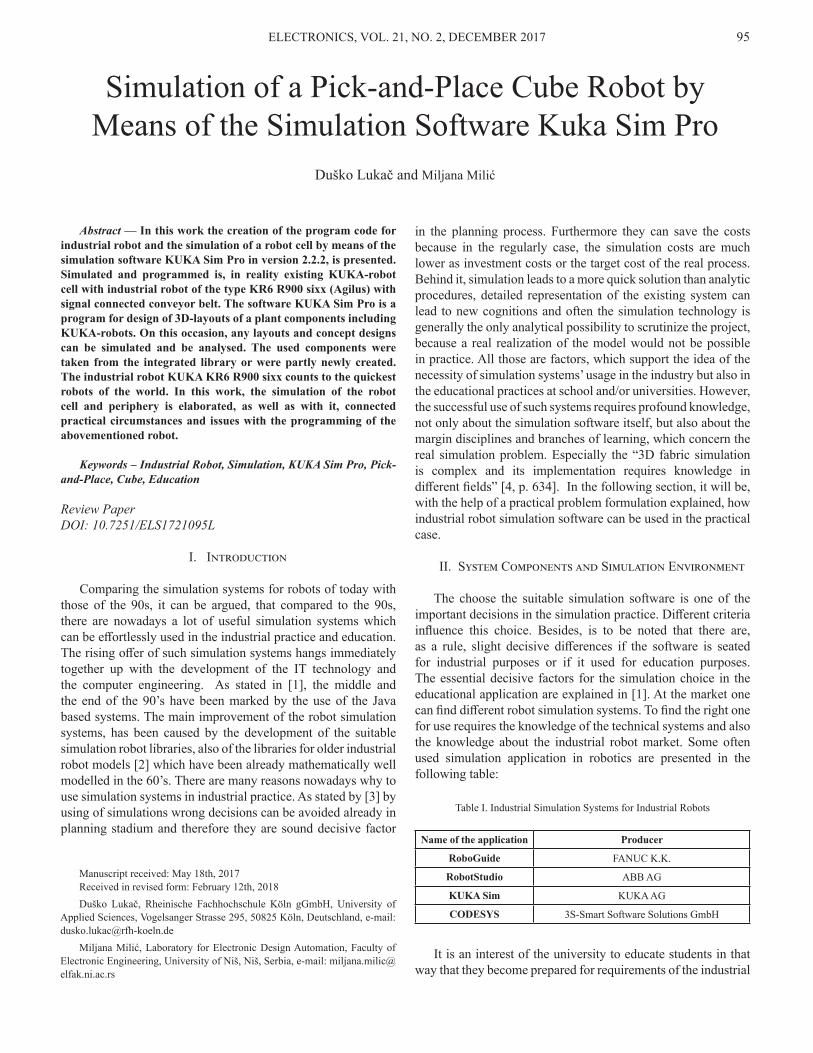
The real simulation environment is introduced in following block representation.
Fig. 1. Block represenataion of the real eviroment
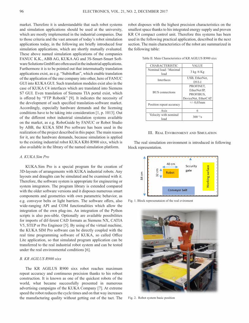
Fig. 2. Robot system basic position
ELECTRONICS, VOL. 21, NO. 2, DECEMBER 2017 97
The purpose of the project is the creation of a program design in addition to the digital simulation of a really existing robot system in Sim KUKA Pro 2.2.2, using the available KUKA KR6 R900 sixx robot and conveyor belt connected with the robot control unit [8]. Once the robot and conveyor belt program are started, if not already in the basic position, the robot moves first in its basic position. This is presented in the Fig. 2. A conveyor belt, with integrated light barrier, transports an aluminium cube with the dimensions (HxWxD): 100 mm x 100 mm x 100 mm in the defined position. As soon as the conveyor belt is launched, the robot moves in the pre-position for removal of the cube and waits, till the workpiece interrupts the light barrier.
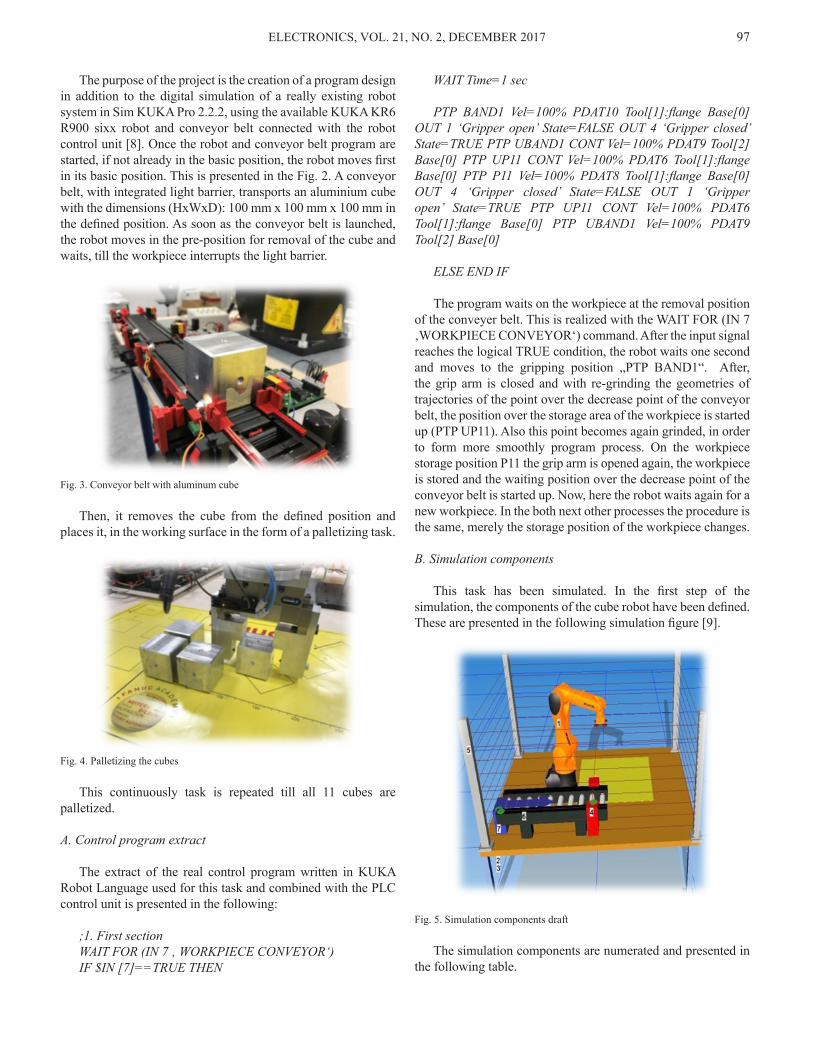
Fig. 3. Conveyor belt with aluminum cube
Then, it removes the cube from the defined position and places it, in the working surface in the form of a palletizing task.
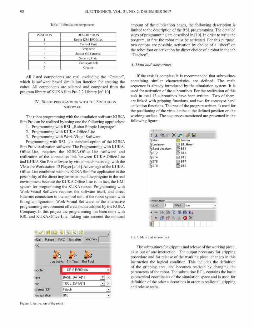
Fig. 4. Palletizing the cubes
This continuously task is repeated till all 11 cubes are palletized.
A. Control program extract
The extract of the real control program written in KUKA Robot Language used for this task and combined with the PLC control unit is presented in the following:
;1. First sectionWAIT FOR (IN 7 ‚ WORKPIECE CONVEYOR‘)IF $IN [7]==TRUE THEN
WAIT Time=1 sec
PTP BAND1 Vel=100% PDAT10 Tool[1]:flange Base[0] OUT 1 ‘Gripper open’ State=FALSE OUT 4 ‘Gripper closed’ State=TRUE PTP UBAND1 CONT Vel=100% PDAT9 Tool[2] Base[0] PTP UP11 CONT Vel=100% PDAT6 Tool[1]:flange Base[0] PTP P11 Vel=100% PDAT8 Tool[1]:flange Base[0] OUT 4 ‘Gripper closed’ State=FALSE OUT 1 ‘Gripper open’ State=TRUE PTP UP11 CONT Vel=100% PDAT6 Tool[1]:flange Base[0] PTP UBAND1 Vel=100% PDAT9 Tool[2] Base[0]
ELSE END IF
The program waits on the workpiece at the removal position of the conveyer belt. This is realized with the WAIT FOR (IN 7 ‚WORKPIECE CONVEYOR‘) command. After the input signal reaches the logical TRUE condition, the robot waits one second and moves to the gripping position „PTP BAND1“. After, the grip arm is closed and with re-grinding the geometries of trajectories of the point over the decrease point of the conveyor belt, the position over the storage area of the workpiece is started up (PTP UP11). Also this point becomes again grinded, in order to form more smoothly program process. On the workpiece storage position P11 the grip arm is opened again, the workpiece is stored and the waiting position over the decrease point of the conveyor belt is started up. Now, here the robot waits again for a new workpiece. In the both next other processes the procedure is the same, merely the storage position of the workpiece changes.
B. Simulation components
This task has been simulated. In the first step of the simulation, the components of the cube robot have been defined. These are presented in the following simulation figure [9].
Fig. 5. Simulation components draft
The simulation components are numerated and presented in the following table.
ELECTRONICS, VOL. 21, NO. 2, DECEMBER 201798
Table III. Simulation components
POSITION DESCRIPTION 1 Robot KR6 R900sixx2 Control Unit3 Peripherie 4 Sensor (H-Sensors)5 Security Gate6 Conveyor belt 7 Creator
All listed components are real, excluding the “Creator”, which is software based simulation function for creating the cubes. All components are selected and composed from the program library of KUKA Sim Pro 2.2 Library [cf. 10]
IV. Robot programming with the Simulation software
The robot programming with the simulation software KUKA Sim Pro can be realized by using one the following approaches:
1. Programming with RSL „Robot Simple Language“2. Programming with KUKA.Office-Lite3. Programming with Work-Visual Software Programming with RSL is a standard option of the KUKA
Sim Pro visualization software. The Programming with KUKA.Office-Lite, requires the KUKA.Office-Lite software and realization of the connection link between KUKA.Office-Lite and KUKA Sim Pro software by virtual machine as e.g. with the VMware Workstation 12 Player [cf. 6]. Advantage of the KUKA.Office-Lite combined with the KUKA Sim Pro application is the possibility of the direct implementation of the program in the real environment because the KUKA.Office-Lite is, in fact, the HMI system for programming the KUKA robots. Programming with Work-Visual Software requires the software itself, and direct Ethernet connection to the control unit of the robot system with fitting configuration. Work-Visual Software, is the alternative programming environment offered and developed by the KUKA Company. In this project the programming has been done with RSL and KUKA.Office-Lite. Taking into account the nominal
amount of the publication pages, the following description is limited to the description of the RSL programming. The detailed steps of programming are described in [10]. In order to write the program, at first the robot must be activated. For this purpose, two options are possible, activation by choice of a “sheet” on the robot foot or activation by direct choice of a robot in the tab “Teachen”.
A. Main and subroutines
If the task is complex, it is recommended that subroutines containing similar characteristics are defined. The main sequence is already introduced by the simulation system. It is used for activation of the subroutines. For the realization of this task in total 13 subroutines have been written. Two of them, are linked with gripping functions, and two for conveyor band activation functions. The rest of the program written, is used for the positioning of the virtual cube at the defined position on the working surface. The sequences mentioned are presented in the following figure:
Fig. 7. Main and subroutines
The subroutines for gripping and release of the working piece, exist out of one instruction. The output necessary for gripping procedure and for release of the working piece, changes in this instruction the logical condition. This includes the definition of the gripping area, and becomes realized by changing the parameters of the robot. The subroutine BT1, contains the basic geometrical coordinates of the simulation space and is used for definition of the other subroutines in order to realize all gripping and release steps.
Figure 6. Activation of the robot
ELECTRONICS, VOL. 21, NO. 2, DECEMBER 2017 99
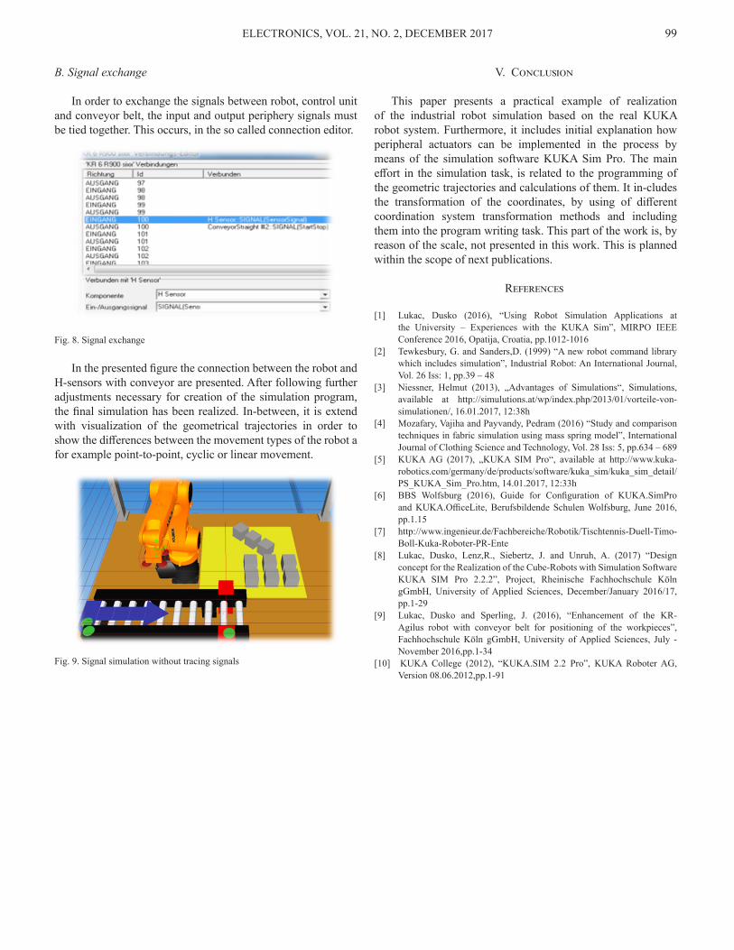
B. Signal exchange
In order to exchange the signals between robot, control unit and conveyor belt, the input and output periphery signals must be tied together. This occurs, in the so called connection editor.
Fig. 8. Signal exchange
In the presented figure the connection between the robot and H-sensors with conveyor are presented. After following further adjustments necessary for creation of the simulation program, the final simulation has been realized. In-between, it is extend with visualization of the geometrical trajectories in order to show the differences between the movement types of the robot a for example point-to-point, cyclic or linear movement.
Fig. 9. Signal simulation without tracing signals
V. Conclusion
This paper presents a practical example of realization of the industrial robot simulation based on the real KUKA robot system. Furthermore, it includes initial explanation how peripheral actuators can be implemented in the process by means of the simulation software KUKA Sim Pro. The main effort in the simulation task, is related to the programming of the geometric trajectories and calculations of them. It in-cludes the transformation of the coordinates, by using of different coordination system transformation methods and including them into the program writing task. This part of the work is, by reason of the scale, not presented in this work. This is planned within the scope of next publications.
References
[1] Lukac, Dusko (2016), “Using Robot Simulation Applications at the University – Experiences with the KUKA Sim”, MIRPO IEEE Conference 2016, Opatija, Croatia, pp.1012-1016
[2] Tewkesbury, G. and Sanders,D. (1999) “A new robot command library which includes simulation”, Industrial Robot: An International Journal, Vol. 26 Iss: 1, pp.39 – 48
[3] Niessner, Helmut (2013), „Advantages of Simulations“, Simulations, available at http://simulutions.at/wp/index.php/2013/01/vorteile-von-simulationen/, 16.01.2017, 12:38h
[4] Mozafary, Vajiha and Payvandy, Pedram (2016) “Study and comparison techniques in fabric simulation using mass spring model”, International Journal of Clothing Science and Technology, Vol. 28 Iss: 5, pp.634 – 689
[5] KUKA AG (2017), „KUKA SIM Pro“, available at http://www.kuka-robotics.com/germany/de/products/software/kuka_sim/kuka_sim_detail/PS_KUKA_Sim_Pro.htm, 14.01.2017, 12:33h
[6] BBS Wolfsburg (2016), Guide for Configuration of KUKA.SimPro and KUKA.OfficeLite, Berufsbildende Schulen Wolfsburg, June 2016, pp.1.15
[7] http://www.ingenieur.de/Fachbereiche/Robotik/Tischtennis-Duell-Timo-Boll-Kuka-Roboter-PR-Ente
[8] Lukac, Dusko, Lenz,R., Siebertz, J. and Unruh, A. (2017) “Design concept for the Realization of the Cube-Robots with Simulation Software KUKA SIM Pro 2.2.2”, Project, Rheinische Fachhochschule Köln gGmbH, University of Applied Sciences, December/January 2016/17, pp.1-29
[9] Lukac, Dusko and Sperling, J. (2016), “Enhancement of the KR-Agilus robot with conveyor belt for positioning of the workpieces”, Fachhochschule Köln gGmbH, University of Applied Sciences, July - November 2016,pp.1-34
[10] KUKA College (2012), “KUKA.SIM 2.2 Pro”, KUKA Roboter AG, Version 08.06.2012,pp.1-91