Electromatic* Ball Valve System
52
Consolidated* 3500-5 Series EBV Electromatic* Ball Valve System Instruction Manual (Rev. D) BHGE Data Classification : Public
Transcript of Electromatic* Ball Valve System
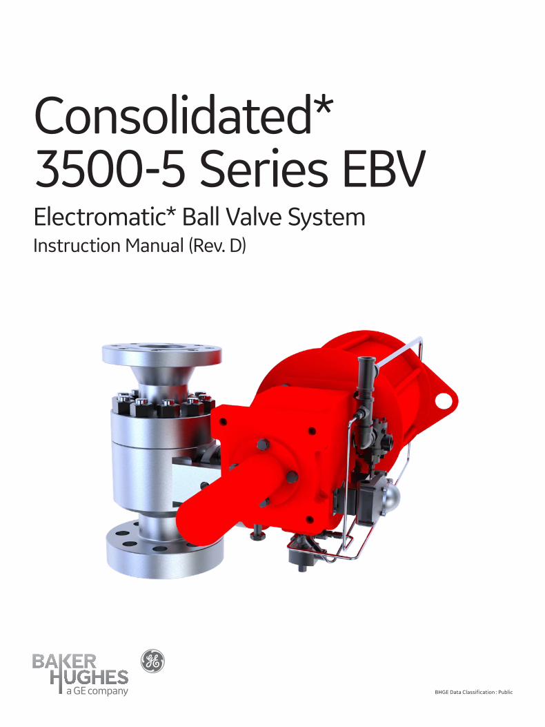
Consolidated*3500-5 Series EBVElectromatic* Ball Valve SystemInstruction Manual (Rev. D)
BHGE Data Classification : Public

ii | BHGE © 2017 Baker Hughes, a GE company. All rights reserved.
THESE INSTRUCTIONS PROVIDE THE CUSTOMER/OPERATOR WITH IMPORTANT PROJECT-SPECIFIC REFERENCE INFORMATION IN ADDITION TO THE CUSTOMER/OPERATOR’S NORMAL OPERATION AND MAINTENANCE PROCEDURES. SINCE OPERATION AND MAINTENANCE PHILOSOPHIES VARY, BAKER HUGHES, A GE COMPANY (BHGE AND ITS SUBSIDIARIES AND AFFILIATES) DOES NOT ATTEMPT TO DICTATE SPECIFIC PROCEDURES, BUT TO PROVIDE BASIC LIMITATIONS AND REQUIREMENTS CREATED BY THE TYPE OF EQUIPMENT PROVIDED.
THESE INSTRUCTIONS ASSUME THAT OPERATORS ALREADY HAVE A GENERAL UNDERSTANDING OF THE REQUIREMENTS FOR SAFE OPERATION OF MECHANICAL AND ELECTRICAL EQUIPMENT IN POTENTIALLY HAZARDOUS ENVIRONMENTS. THEREFORE, THESE INSTRUCTIONS SHOULD BE INTERPRETED AND APPLIED IN CONJUNCTION WITH THE SAFETY RULES AND REGULA-TIONS APPLICABLE AT THE SITE AND THE PARTICULAR REQUIREMENTS FOR OPERATION OF OTHER EQUIPMENT AT THE SITE.
THESE INSTRUCTIONS DO NOT PURPORT TO COVER ALL DETAILS OR VARIATIONS IN EQUIPMENT NOR TO PROVIDE FOR EVERY POSSIBLE CONTINGENCY TO BE MET IN CONNECTION WITH INSTALLATION, OPERATION OR MAINTENANCE. SHOULD FURTHER INFORMATION BE DESIRED OR SHOULD PARTICULAR PROBLEMS ARISE WHICH ARE NOT COVERED SUFFICIENTLY FOR THE CUSTOMER/OPERATOR’S PURPOSES THE MATTER SHOULD BE REFERRED TO BHGE.
THE RIGHTS, OBLIGATIONS AND LIABILITIES OF BHGE AND THE CUSTOMER/OPERATOR ARE STRICTLY LIMITED TO THOSE EXPRESSLY PROVIDED IN THE CONTRACT RELATING TO THE SUPPLY OF THE EQUIPMENT. NO ADDITIONAL REPRESENTATIONS OR WARRANTIES BY BHGE REGARDING THE EQUIPMENT OR ITS USE ARE GIVEN OR IMPLIED BY THE ISSUE OF THESE INSTRUC-TIONS.
THESE INSTRUCTIONS ARE FURNISHED TO THE CUSTOMER/OPERATOR SOLELY TO ASSIST IN THE INSTALLATION, TESTING, OP-ERATION, AND/OR MAINTENANCE OF THE EQUIPMENT DESCRIBED. THIS DOCUMENT SHALL NOT BE REPRODUCED IN WHOLE OR IN PART TO ANY THIRD PARTY WITHOUT THE WRITTEN APPROVAL OF BHGE.

Consolidated 3500-5 Series EBV Instruction Manual | iii© 2017 Baker Hughes, a GE company. All rights reserved.
NOTICE!
For valve configurations not listed in this manual, please contact your local Green Tag* Center for assistance.
All the United States Customary System (USCS) values are converted to metric values using
the following conversion factors:
USCS Unit Conversion Factor Metric Unit
in. 25.4 mm
lb. 0.4535924 kg
in2 6.4516 cm2
ft3/min 0.02831685 m3/min
gal/min 3.785412 L/min
lb/hr 0.4535924 kg/hr
psig 0.06894757 barg
ft lb 1.3558181 Nm
°F 5/9 (°F-32) °C
Conversion Table
Note: Multiply USCS value with conversion factor to get metric value.

iv | BHGE © 2017 Baker Hughes, a GE company. All rights reserved.

Consolidated 3500-5 Series EBV Instruction Manual | 1© 2017 Baker Hughes, a GE company. All rights reserved.
ContentsConversion Table ����������������������������������������������������������������������������������������������������������� iii
Product Safety Sign and Label System ���������������������������������������������������������������������� 2
Safety Alerts �������������������������������������������������������������������������������������������������������������������� 3
Safety Precautions ��������������������������������������������������������������������������������������������������������� 4
Safety Notice ������������������������������������������������������������������������������������������������������������������� 5
Handling and Storage ���������������������������������������������������������������������������������������������������� 6
Warranty Information ��������������������������������������������������������������������������������������������������� 7
Valve Terminology ���������������������������������������������������������������������������������������������������������� 7
3500-5 Series EBVA. Design Features and Nomenclature.................................................................................................9
B. Environmental Conditions .................................................................................................................. 10
C. Introduction ............................................................................................................................................... 10
D. 3500-5 EBV Typical Flange Inlet ...................................................................................................... 11
E. 3500-5 EBV Typical Buttweld Inlet .................................................................................................11
F. 3500-5 EBV Actuator Assembly ...................................................................................................... 12
G. Pressure Regulator and Filter .............................................................................................................14
H. Auxiliary Supply Manifold ....................................................................................................................14
Operating Principles ............................................................................................................... 15
Recommended Installation Practices ...................................................................................................... 16
General Operating Instructions .................................................................................................................. 18
Maintenance Instructions .............................................................................................................................. 19
Inspection and Part Replacement ............................................................................................................. 23
Lifting and Handling ............................................................................................................................................24
Welding Instructions ......................................................................................................................................... 25
Disassembly ........................................................................................................................................................... 28
Reassembly ............................................................................................................................................................ 33
Setting and Testing ............................................................................................................................................ 40
Operations .............................................................................................................................................................. 43
Quick Reference Guide ..................................................................................................................................... 45
Maintenance .......................................................................................................................................................... 46
Troubleshooting ....................................................................................................................................................47

2 | BHGE © 2017 Baker Hughes, a GE company. All rights reserved.
If and when required, appropriate safety labels have been included in the rectangular margin blocks throughout this manual. Safety labels are vertically oriented rectangles as shown in the representative examples (below), consisting of three panels encircled by a narrow border. The panels can contain four messages which communicate:
• The level of hazard seriousness
• The nature of the hazard
• The consequence of human, or product, interaction with the hazard.
• The instructions, if necessary, on how to avoid the hazard.
The top panel of the format contains a signal word (DANGER, WARNING, CAUTION or ATTENTION) which communicates the level of hazard seriousness.
The center panel contains a pictorial which communicates the nature of the hazard, and the possible consequence of human or product interaction with the hazard. In some instances of human hazards the pictorial may, instead, depict what preventive measures to take, such as wearing protective equipment.
The bottom panel may contain an instruction message on how to avoid the hazard. In the case of human hazard, this message may also contain a more precise definition of the hazard, and the consequences of human interaction with the hazard, than can be communicated solely by the pictorial.
Product Safety Sign and Label System
Do not remove bolts if pressure in line, as this
will result in severe personal injury or death�
Immediate hazards which WILL result in
severe personal injury or death�
Know all valve exhaust/leakage points to
avoid possible severe personal injury or death�
Hazards or unsafe practices which COULD
result in severe personal injury or death�
Wear necessary protective equipment
to prevent possible injury�
Hazards or unsafe practices which COULD result in minor personal
injury�
Handle valve carefully� Do not drop or strike�
Hazards or unsafe practices which COULD
result in product or property damage

Consolidated 3500-5 Series EBV Instruction Manual | 3© 2017 Baker Hughes, a GE company. All rights reserved.
Safety Alerts
Read - Understand - Practice
Danger AlertsA DANGER alert describes actions that may cause severe personal injury or death. In addition, it may provide preventive measures to avoid severe personal injury or death.
DANGER alerts are not all-inclusive. BHGE cannot know all conceivable service methods nor evaluate all potential hazards. Dangers include:
• High temperature/pressure can cause injury. Ensure all system pressure is absent before repairing or removing valves.
• Do not stand in front of a valve outlet when discharging. STAND CLEAR OF VALVE to avoid exposure to trapped, corrosive media.
• Exercise extreme caution when inspecting a pressure relief valve for leakage.
• Allow the system to cool to room temperature before cleaning, servicing, or repairing. Hot components or fluids can cause severe personal injury or death.
• Always read and comply with safety labels on all containers. Do not remove or deface container labels. Improper handling or misuse could result in severe personal injury or death.
• Never use pressurized fluids/gas/air to clean clothing or body parts. Never use body parts to check for leaks, flow rates, or areas. Pressurized fluids/gas/air injected into or near the body can cause severe personal injury or death.
• It is the owner’s responsibility to specify and provide personal protective wear to protect persons from pressurized or heated parts. Contact with pressurized or heated parts can result in severe personal injury or death.
• Do not work or allow anyone under the influence of intoxicants or narcotics to work on or around pressurized systems. Workers under the influence of intoxicants or narcotics are a hazard to themselves and other employees. Actions taken by an intoxicated employee can result in severe personal injury or death to themselves or others.
• Always perform correct service and repair. Incorrect service and repair can result in product or property damage or severe personal injury or death.
• Always use the correct tool for a job. The misuse of a tool or the use of an improper tool can result in personal injury, damage to product or property.
• Ensure the proper “health physics” procedures are followed, if applicable, before starting operation in a radioactive environment.
Caution AlertsA CAUTION alert describes actions that may result in a personal injury. In addition, they may describe preventive measures that must be taken to avoid personal injury. Cautions include:
• Heed all service manual warnings. Read installation instructions before installing valve(s).
• Wear hearing protection when testing or operating valves.
• Wear appropriate eye and clothing protection.
• Wear protective breathing apparatus to protect against toxic materials.

4 | BHGE © 2017 Baker Hughes, a GE company. All rights reserved.
Follow all plant safety regulations, but be sure to observe the following:
• Always lower the working pressure before making any valve adjustment. When making ring adjustments, always gag the valve before making the adjustment. This will avoid possible personal injury.
• Do not stand in front of the discharge side of a safety valve when testing or operating.
• Hearing and eye protection should be used when testing or operating a valve.
• Wear protective clothing. Hot water can burn and superheated steam is not visible.
• When removing the safety valve during disassembly, stand clear and/or wear protective clothing to prevent exposure to splatter or any corrosive process medium, which may have been trapped inside the valve. Ensure the valve is isolated from system pressure before the valve is removed.
• Exercise care when examining a safety valve for leakage.
• Prior to each actuation, assure that no personnel are near the valve. Steam escaping from the valve during actuation can possibly cause personal injury.
• When popping a safety valve for the first time or after refurbishment, always be prepared to actuate the valve with the lever while standing in a safe place away from the valve. This may be done by fixing a rope to the lever for actuating the valve from a distance.
• Striking a valve which is under pressure can cause premature actuation. Never tamper with the valve when system pressure is near the valve set pressure.
• Before performing any machining on valve parts, consult BHGE or its authorized representative. Deviation from critical dimensions can adversely affect valve performance.
Lower pressure and stand clear of discharge when
working on valve to avoid severe personal injury or
death�
Safety Precautions
Know all valve exhaust/leakage points to avoid
possible severe personal injury or death�

Consolidated 3500-5 Series EBV Instruction Manual | 5© 2017 Baker Hughes, a GE company. All rights reserved.
Proper installation and start-up is essential to the safe and reliable operation of all valve products. The relevant procedures recommended by BHGE, and described in these instructions, are effective methods of performing the required tasks.
It is important to note that these instructions contain various “safety messages” which should be carefully read in order to minimize the risk of personal injury, or the possibility that improper procedures will be followed which may damage the involved BHGE product, or render it unsafe. It is also important to understand that these “safety messages” are not exhaustive. BHGE can not possibly know, evaluate, and advise any customer of all of the conceivable ways in which tasks might be performed, or of the possible hazardous consequences of each way.
Consequently, BHGE has not undertaken any such broad evaluation and, thus, anyone who uses a procedure and/or tool, which is not recommended by BHGE, or deviates from BHGE recommendations, must be thoroughly satisfied that neither personal safety, nor valve safety, will be jeopardized by the method and/or tools selected. If not so satisfied, contact BHGE (at 1-844-VALVE-GE or 1-281-884-1000) if there are any questions relative to tools/methods.
The installation and start-up of valves and/or valve products may involve proximity to fluids at extremely high pressure and/or temperature. Consequently, every precaution should be taken to prevent injury to personnel during the performance of any procedure. These precautions should consist of, but are not limited to, ear drum protection, eye protection, and the use of protective clothing, (i.e., gloves, etc.) when personnel are in, or around, a valve work area. Due to the various circumstances and conditions in which these operations may be performed on BHGE products, and the possible hazardous consequences of each way, BHGE can not possibly evaluate all conditions that might injure personnel or equipment.
It is the responsibility of the purchaser or user of BHGE valves/equipment to adequately train all personnel who will be working with the involved valves/equipment. For more information on training schedules, call 1-281-542-3650. Further, prior to working with the involved valves/equipment, personnel who are to perform such work should become thoroughly familiar with the contents of these instructions.
Wear necessary protective equipment to prevent possible injury�
Safety Notice

6 | BHGE © 2017 Baker Hughes, a GE company. All rights reserved.
CAUTION: Do not handle the valve assembly by attaching lifting devices to the actuator alone; the lifting
points on the actuator are not rated to safely lift the entire valve and actuator.
Handling and Storage
Never attempt to lift the full weight of the valve by the actuator tubing, solenoid valve, junction box, etc.
EBV valves should be stored, in their original shipping crates, in a dry environment, to protect them from the weather. They should not be removed from the crates until immediately prior to installation.
The inlet and oulet protectors should not be removed until the valves are ready for installation into the system.
EBV valves, either crated or un-crated, should never be subjected to sharp impact. This would most likely to occur by bumping or dropping during loading or unloading from a truck, or while moving with a power conveyor, such as a fork lift truck, or while hoisting during installation, care should be exercised to prevent bumping the valve against structures or other objects.
When EBV valves are un-crated, and the inlet and outlet protectors are removed immediately prior to the installation, meticulous care should be exercised to prevent dirt, or other foreign materials, from entering the inlet and outlet ports while installing the valves.
Some EBV valves are supplied with lifting devices attached to the discharge collar flange. When supplied, use these lifting devices to safety handle the valve assembly.
If lifting devices are not supplied, the valve mounting bracket can be a safe option to lift and handle the valve assembly. Support or lift as required, using lifting lugs or nylon straps around the valve body. Do not lift or support by the actuator alone.
Do not position inlet flange horizontally, or lift valve by tubing assembly
or external devices�
Improper tools or improper use of right tools could result in
personal injury or product damage�
Improper tools or improper use of right tools could result in
personal injury or product damage�
Please use caution when lifting the EBV assembly so not to damage any actuator accessories; i.e. tubing, switches, etc.
Consolidated 3500-5 Series EBV Instruction Manual | 7© 2017 Baker Hughes, a GE company. All rights reserved.
Warranty Information
Warranty Statement - BHGE warrants that its products and work will meet all applicable specifications and other specific product and work requirements and will be free from defects in material and workmanship. Refer to BHGE’s Standard Terms of Sale, or specific contract for complete details on warranty and limitation of remedy and liability.
Defective and nonconforming items must be held for BHGE’s inspection and returned to the original F.O.B. point upon request .
Incorrect Selection or Misapplication of Products - BHGE cannot be responsible for customer ’s incorrect selection or misapplication of our products.
Unauthorized Repair Work - BHGE has not authorized any non-BHGE affiliated repair companies, contractors or individuals to perform modifications or services on new products or field repaired products of its manufacture. Therefore, customers contracting for such services or performing such services on their own do so at their own risk.
Unauthorized Removal of Seals - All new valves and valves repaired in the field by BHGE’s affiliated repair companies are sealed to assure the customer of our guarantee against defective workmanship. Unauthorized removal and/or breakage of this seal will negate our warranty.
• Back Pressure
Back pressure is the static pressure existing at the outlet of a safety valve device due to pressure in the discharge system.
• Blowdown
Blowdown is the difference between actual popping pressure of a safety valve and actual reseating pressure expressed as a percentage of set pressure, or in pressure units.
• Bore Area
Bore area is the minimum cross-sectional area of the orifice.
• Bore Diameter
Bore diameter is the minimum diameter of the seat bushing.
• Built-Up Back Pressure
Pressure existing at the outlet of a safety valve while it is open and flowing through a discharge system.
• Chatter
Chatter is abnormal, rapid reciprocating motion of the moveable parts of a safety valve, in which the disc contacts the seat.
• Closing Pressure
Closing pressure is the value of decreasing inlet static pressure at which the valve disc re-establishes contact with the seat, or at which lift becomes zero.
• Disc
A disc is the pressure containing moveable member of a safety valve which effects closure.
• Inlet Size
Inlet size is the nominal pipe size of the inlet of a safety valve, unless otherwise designated.
• Leak Test Pressure
Leak test pressure is the specified inlet static pressure at which a quantitative seat leakage test is performed in accordance with a standard procedure.
• Lift
Lift is the actual travel of the disc away from closed position when a valve is relieving.
• Lifting Device
A lifting device is a device for manually opening a safety valve, by the application of external force to lessen the spring loading which holds the valve closed.
• Seat Bushing
A seat bushing is the pressure containing element which constitutes the inlet flow passage and includes the fixed portion of the seat closure.
• Outlet Size
Outlet size is the nominal pipe size of the outlet passage of a safety valve, unless otherwise designated.
• Overpressure
Overpressure is a pressure increase over the set pressure of a safety valve, usually expressed as a percentage of set pressure.
• Popping Pressure
Popping pressure is the value of increasing inlet static pressure at which the disc moves in the opening direction at a faster rate as compared with corresponding movement at higher or lower pressures. It applies only to safety or safety relief valves on compressible fluid service.
Valve Terminology(Paraphrased from ASME’s PTC 25)
8 | BHGE © 2017 Baker Hughes, a GE company. All rights reserved.
Valve Terminology (Contd.)
• Pressure Containing Member
A pressure containing member of a safety valve is a part which is in actual contact with the pressure media in the protected vessel.
• Pressure Retaining Member
A pressure retaining member of a safety valve is a part which is stressed due to its function in holding one or more pressure containing members in position.
• Rated Lift
Rated lift is the design lift at which a valve attains its rated relieving capacity.
• Safety Valve
A safety valve is a pressure relief valve actuated by inlet static pressure and characterized by rapid opening or pop action.
• Set Pressure
Set pressure is the value of increasing inlet static pressure at which a safety valve displays the operational characteristics as defined under “Popping Pressure.” It is one value of pressure stamped on the safety valve.
• Seat
A seat is the pressure containing contact between the fixed and moving portions of the pressure containing elements of a valve.
• Seat Diameter
Seat diameter is the smallest diameter of contact between the fixed and moving members of the pressure containing elements of a valve.
• Seat Tightness Pressure
Seat tightness pressure is the specific inlet static pressure at which a quantitative seat leakage test is performed in accordance with a standard procedure.
• Simmer
Simmer is the audible or visible escape of fluid between the seat and disc at an inlet static pressure below the popping pressure and at no measurable capacity. It applies to safety valves on compressible fluid service.
• Warn
See “Simmer” (definition above).

Consolidated 3500-5 Series EBV Instruction Manual | 9© 2017 Baker Hughes, a GE company. All rights reserved.
3500-5 Series EBV
A. Design Features and NomenclatureThe MVC-5000 digital controller requires a pressure transmitter/transducer to read the system pressure. The pressure transducer is powered by the MVC-5000 digital controller where a 4-20 mA signal is read.
Additionally a siphon tube is required to protect the pressure transmitter by dissipating heat (reducing incoming fluid temperature) and allowing the fluid to condensate.
The customer should connect the system pressure line/pipe to the siphon coil first, before connecting the pressure transducer.
Figure 1 illustrates the relationship of the various elements of the Power Actuated Relief Valve System.
The MVC-5000 digital controller consists of a touchscreen display module and pluggable terminal board, enclosed within a rugged NEMA 4X/IP68 aluminum or stainless steel window housing. Local indication is provided for AUTO/OPEN mode selection, real-time pressure display, set and reseat pressure.
For automatic overpressure control, pressure data is transmitted to the controller by the 4-20mA PT400 pressure transducer. The MVC-5000 may also be controlled manually from the local touchscreen, local switch box, Modbus remote panel, or DCS remote panel. The plug-and-play Modbus remote panel is a small touch screen which mirrors the local controller display and functionality. The DCS remote panel consists of OPEN and AUTO mode indicating lights and a hand switch. The Triac actuators assembly consists of a double acting pneumatic actuator, solenoid valve and a limit switch. The electrical supply system consists of a control circuit and a solenoid circuit.
The field wiring must have insulation suitable for at least 600 volts. The solenoid insulation is Class F.
Figure 1: Typical Electromatic Ball Valve System
Remote Panel (Optional)
Transducer
Isolation Ball
Electromatic
Ball Valve
Nitrogen Tanks w/Regulator
Boiler Drum
Valve
Super Heater
Instrument Air Supply (Standard 80 psig)
(40 psig min. - 120 psig max.)
Syphon
System Supply Voltage
Control
Voltage
Supply
Optional Manifold System
Digital
Controller
Safety
Valve

10 | BHGE © 2017 Baker Hughes, a GE company. All rights reserved.
3500-5 Series EBV (Cont’d.)
C. IntroductionThe BHGE Electromatic Ball Valve is an electrically controlled power actuated pressure relief device. It may be manually operated by direct command on the controller screen/remote panel, or automatically operated at specified opening and closing pressure. The application provides the plant operator with a means of instantaneously opening and closing a relief valve at a remote location.
When the pressure controller is set to open the Electromatic Ball Valve at a pressure slightly below the lowest set spring loaded safety valves, it will prevent the safety valves from opening except during major overpressure excursions.
B. MVC-5000 Digital Controller Environmental Conditions
• Indoor or outdoor use.
• Elavation (maximum) 3000 M.
• Operating ambient temperature maximum 140°F (60°C). (cTUVus certified at 55°C maximum)
• Pollution Degree - 2.
• Over voltage category III.
• Main supply voltage fluctuations +10% - 5% of the nominal voltage.
• Protection Classification: Safe Areas.
• Remote Panel Ratings: Safe Areas, IP65 (panel mounted).

Consolidated 3500-5 Series EBV Instruction Manual | 11© 2017 Baker Hughes, a GE company. All rights reserved.
D. 3500-5 EBV Typical Flange Inlet
E. 3500-5 EBV Typical Buttweld Inlet
3500-5 Series EBV (Cont’d.)
PartNo�
Nomenclature
123
3A3B3C3D3E3F456789
10 11A 11B1213141516171819202122232425
261
271
BodyDischarge CollarBall & Seat AssemblySeatBallLoaderSpiralwave SpringSpacer RingOrificeGasketStemGuide BearingPacking Gland FlangePacking FollowerPacking RingPacking BushingDischarge Collar StudsDischarge Collar NutsStud Packing GlandNut Packing GlandOuter CollarOuter PinInner CollarInner PinKey StemDrainMounting FlangeGland SpringsThrust WasherRing RetainerCollar Retaining SleeveMounting LegMounting Flange StudsMounting Flange Nuts
1 Not Shown.
2
17
8
1321
14
18
23
246
416
3C3B3A
3F
3D 3E
20
15
1
910
5
7
1911A 11B
12
2226 27
25
6
3F
12 3A 3B 3C 3D 3E19
8
21
2414
18
13
4 17
20
1525
9
5
7
16
10
11B11A
12
23 2226 27

12 | BHGE © 2017 Baker Hughes, a GE company. All rights reserved.
F. 3500-5 EBV Actuator Assembly - Triac Actuator Style 1
3500-5 Series EBV (Cont’d.)
PartNo�
Nomenclature
2525A25D25E25F1
25G1
25H1
25J1
25K25L25M25P25R25S25T25U
Actuator AssemblySolenoidPosition SwitchBracketCap Screw Bracket/ActuatorLock Washer Bracket/ActuatorCap Screw Bracket/SwitchLock Washer Bracket/SwitchClose Nipple PipeFlush BushingConduit Fitting StraightTee PipeElbow PipeTubingTube Fitting Union ElbowTube Fitting Union
1 Not Shown.
25
25D
25E
25A
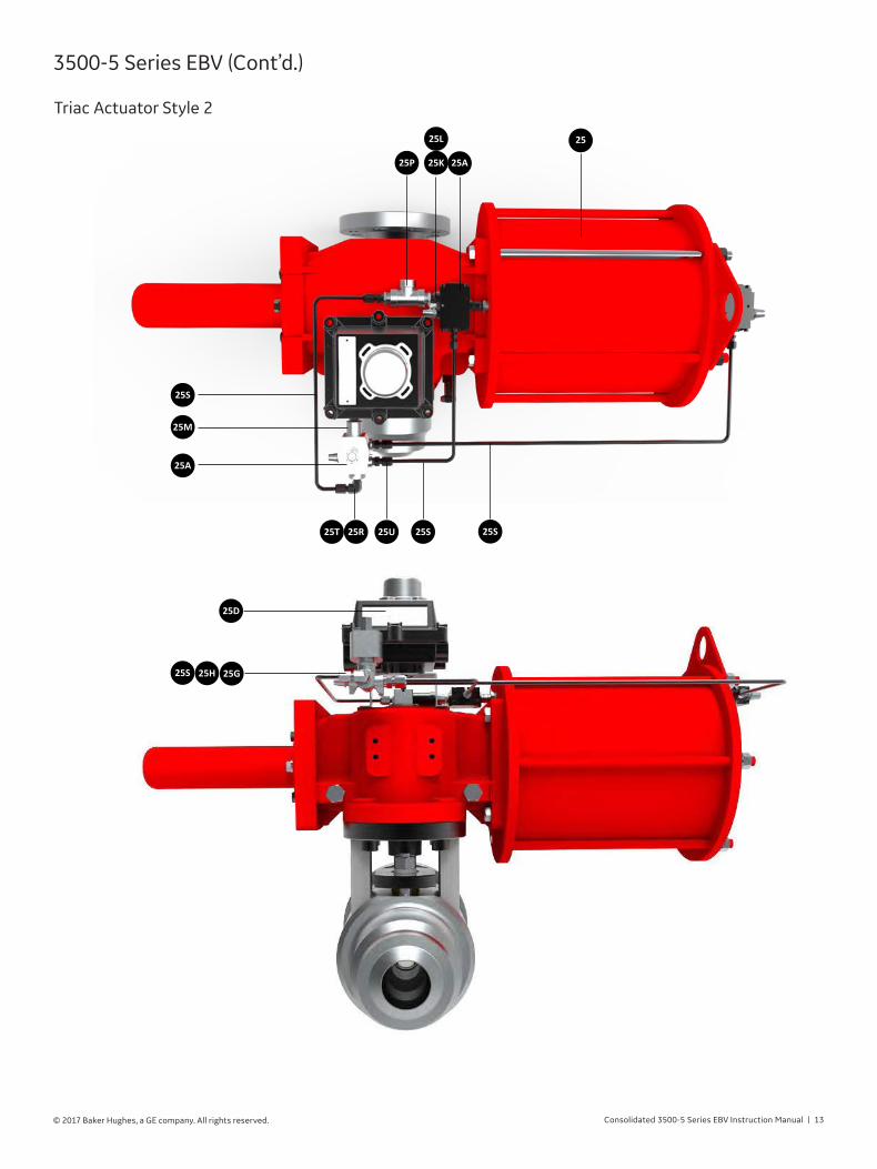
Consolidated 3500-5 Series EBV Instruction Manual | 13© 2017 Baker Hughes, a GE company. All rights reserved.
3500-5 Series EBV (Cont’d.)
25M
25S
25A
25T 25R 25U 25S 25S
25A
25
25P 25K
25L
25D
25G25H25S
Triac Actuator Style 2

14 | BHGE © 2017 Baker Hughes, a GE company. All rights reserved.
G. Pressure Regulator and Filter
H. Auxiliary Supply Manifold
PartNo�
Nomenclature
262728293031
Pressure RegulatorFilterCheck ValveCross PipeThread ProtectorRelief Valve
27
26
28
28
29
31
30
3500-5 Series EBV (Cont’d.)

Consolidated 3500-5 Series EBV Instruction Manual | 15© 2017 Baker Hughes, a GE company. All rights reserved.
Operating Principles
3500-5 EBVDigital Controller
with External Switchbox
DCS Push Button Remote Panel
Modbus TouchscreenRemote Panel
3500-5 EBVDigital Controller
ASME Section I Power Actuated Relief Valve (PARV) In the “PARV” configuration, the MVC-5000 operates as a sophisticated digital pressure switch. While continuously monitoring process pressure through a high precision ADC, the MVC-5000 automatically operates a power actuated relief valve according to the user’s programmed set pressure and blow down criteria. This configuration can be used to control ASME and non-ASME capacity certified EBVs. The EBV configuration also includes provisions for DCS and manual override. For more information please visit the following links:
MVC-5000 Installation Operation and Maintenance Manual:
http://mightyinstruments.com/images/datasheets/MVC-5000PARV%20-%20IOM%202.pdf
MVC-5000 Datasheet:
http://mightyinstruments.com/images/datasheets/MVC-5000%20Datasheet%20PARV%20R3.pdf
External SwitchboxThe ASME certified MVC-5000 housing is sealed closed after installation, leaving the local touch screen inaccessible in normal operating conditions. The MVC5000 Switch Box is a simple bolt-on that outfits the MVC with local hand controls so that the operator can control the device without removing the cover. Each box contains a 3 position, normally closed, selector switch. Two positions initiate commands (AUTO and OPEN), while the 3rd mid position removes both commands from the MVC so that other devices may take control.
• Ingress Protection: NEMA 4X, IP66
Remote Panel OptionsThe remote panels, which are offered in 2 varieties (DCS push buttons and Modbus touchscreen), are small units that can be mounted on the plant control panel. The DCS control station is hardwired to the MVC’s discrete I/O, while the Modbus control station is connected to the MVC’s RS-485 serial port. Both versions provide for remote control and communication with the MVC-5000.
DCS Remote PanelThe DCS remote panel consists of 2 lights and a 3 position switch. The Open and Closed lights indicate actual valve position. The selector switch is used to command the controller either in Auto Mode or Open Mode. In Auto Mode, the controller operates the valve autonomously in response to system pressure. In Open Mode, the controller manually opens the valve, regardless of system pressure.
• Ingress Protection: IP65 (panel mounted)
Modbus Touchscreen Remote PanelThe Modbus touchscreen remote panel consists of a 3.5” color touchscreen, which duplicates the local MVC-5000 touchscreen display. Commands and feedback are sent through the MVC-5000’s RS-485 Modbus link. Auto/Open Modes and device configuration parameters can all be set from the Modbus control station. Set/Re-Seat and actual system pressure are also relayed to the control station for remote readout.
• Ingress Protection: IP66 (panel mounted)

16 | BHGE © 2017 Baker Hughes, a GE company. All rights reserved.
Recommended Installation Practices
The Electromatic Ball Valve (EBV) is customarily installed either on a superheater, or on a manifold fed by two or more boilers.
To facilitate servicing, an Isolation Ball Valve (IBV) should be installed directly below the Main Valve, as shown in Figure 1 (Refer to ASME Code Restrictions for code stamped valves).
Care should be taken to ensure that mechanical strains from the discharge piping are not transmitted to the Electromatic Ball Valve. Such Strains are detrimental to good valve performance.
The discharge pipes should have adequate steam capacity and should be of a size to provide for movement caused by thermal expansion.
Discharge piping should be drained to prevent the accumulation of water in the valve outlet. At no time should the discharge piping rest against the drip pan, or the nipple therein. The riser piping should be securely anchored to the building structure, and never to the valve, in order for it to resist the reactive forces of the discharged steam. The Drains should be piped in such a manner as to prevent the unnecessary escape of steam into any enclosure, and to keep foreign material from being blown back into the valve from other sources (Refer to Figure 2). Cover the main valve outlet, during system shut downs, when the valve is not in service, or is not pressurized, to prevent foreign matter from entering into the main valve.
Figure 2: Recommended Exhaust Stack Installation
IMVC-5000 Digital Controller
It is recommended that the Controller be mounted directlyto the building structure and, depending on the installation.The digital controller can operate under vibration from thebuilding structure and pressure vessel without the requirementto eliminate the vibration. Because pressure reading is entirelyelectronic, sock absorbing material is not required to mount thecontroller.
Additionally, the pressure sensing connection should bemounted at least eight to ten pipe diameters upstream fromthe Electromatic Ball Valve in order to provide a stable pressuresignal.
Required Wire Gauge
The electrical supply to the controller (solenoid voltage) should havestranded wiring. The recommended minimum wire gauge is 18 AWGto limit voltage sag to -5% during current inrush. The compact natureof the MVC5000 enclosure makes larger wire impractical.
Terminals
Parameter Power Terminal Control Terminals
Wire Size12-30 AWG (18 AWG recommended)
16-30 AWG (20 AWG recommended)

Consolidated 3500-5 Series EBV Instruction Manual | 17© 2017 Baker Hughes, a GE company. All rights reserved.
Figure 2: Recommended Exhaust Stack Installation
General Operating Instructions
CAUTION!Actuators shall not be mounted, removed, adjusted or re-installed on BHGE valves except by properly trained
personnel.
CAUTION!Valve must be installed with the FLOW ARROW point-ing from high pressure to low pressure with the valve
in the closed isolating position.
Orientation
CAUTION: Valve Actuators must be installed, operated, and maintained as per the manufacturer’s written instructions.
CAUTION:Valve Actuators never use the valve as a structural member!
CAUTION:Valve Actuator is not designed for end of line use!
18 | BHGE © 2017 Baker Hughes, a GE company. All rights reserved.
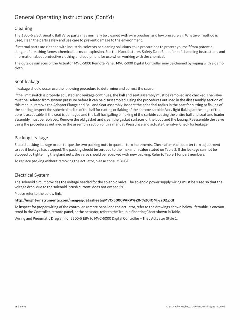
CleaningThe 3500-5 Electromatic Ball Valve parts may normally be cleaned with wire brushes, and low pressure air. Whatever method is used, clean the parts safely and use care to prevent damage to the environment.
If internal parts are cleaned with industrial solvents or cleaning solutions, take precautions to protect yourself from potential danger of breathing fumes, chemical burns, or explosion. See the Manufacture’s Safety Data Sheet for safe handling instructions and information about protective clothing and equipment for use when working with the chemical.
The outside surfaces of the Actuator, MVC-5000 Remote Panel, MVC-5000 Digital Controller may be cleaned by wiping with a damp cloth.
Seat leakage If leakage should occur use the following procedure to determine and correct the cause:
If the limit switch is properly adjusted and leakage continues, the ball and seat assembly must be removed and checked. The valve must be isolated from system pressure before it can be disassembled. Using the procedures outlined in the disassembly section of this manual remove the Adapter Flange and Ball and Seat assembly. Inspect the spherical radius in the seat for cutting or flaking of the coating. Inspect the spherical radius of the ball for cutting or flaking of the chrome carbide. Very light flaking at the edge of the bore is acceptable. If the seat is damaged and the ball has galling or flaking of the carbide coating the entire ball and seat and loader assembly must be replaced. Remove the old gasket and clean the gasket surfaces of the body and the busing. Reassemble the valve using the procedures outlined in the assembly section of this manual. Pressurize and actuate the valve. Check for leakage.
Packing LeakageShould packing leakage occur, torque the two packing nuts in quarter-turn increments. Check after each quarter turn adjustment to see if leakage has stopped. The packing should be torqued to the maximum value stated on Table 2. If the leakage can not be stopped by tightening the gland nuts, the valve should be repacked with new packing. Refer to Table 1 for part numbers.
To replace packing without removing the actuator, please consult BHGE.
Electrical SystemThe solenoid circuit provides the voltage needed for the solenoid valve. The solenoid power supply wiring must be sized so that the voltage drop, due to the solenoid inrush current, does not exceed 5%.
Please refer to the below link:
http://mightyinstruments�com/images/datasheets/MVC-5000PARV%20-%20IOM%202�pdf
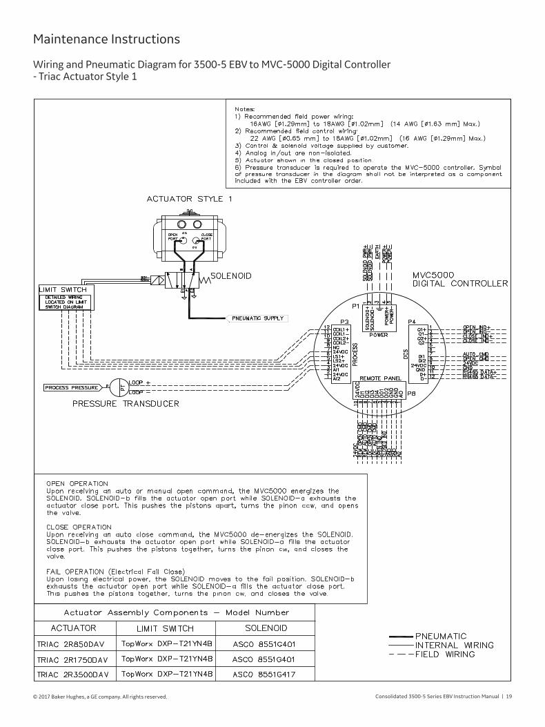
To inspect for proper wiring of the controller, remote panel and the actuator, refer to the drawings shown below. If trouble is encoun-tered in the Controller, remote panel, or the actuator, refer to the Trouble Shooting Chart shown in Table.
Wiring and Pneumatic Diagram for 3500-5 EBV to MVC-5000 Digital Controller – Triac Actuator Style 1.
General Operating Instructions (Cont’d)
Consolidated 3500-5 Series EBV Instruction Manual | 19© 2017 Baker Hughes, a GE company. All rights reserved.
Maintenance Instructions
Wiring and Pneumatic Diagram for 3500-5 EBV to MVC-5000 Digital Controller- Triac Actuator Style 1

20 | BHGE © 2017 Baker Hughes, a GE company. All rights reserved.
Maintenance Instructions
Wiring and Pneumatic Diagram for 3500-5 EBV to MVC-5000 Digital Controller- Triac Actuator Style 2

Consolidated 3500-5 Series EBV Instruction Manual | 21© 2017 Baker Hughes, a GE company. All rights reserved.
Maintenance Instructions
Wiring Diagram for Limit Switch to MVC-5000 Digital Controller

22 | BHGE © 2017 Baker Hughes, a GE company. All rights reserved.
Maintenance Instructions
Wiring Diagram MVC-5000 Digital Controller to Accessories

Consolidated 3500-5 Series EBV Instruction Manual | 23© 2017 Baker Hughes, a GE company. All rights reserved.
Inspection and Part Replacement
Visually inspect all parts for cleanliness and the presence of foreign materials. Clean and reinspect as necessary. Inspect the carbide coating of the ball, seat, seat loader, stem and bearing washer for cracking or flaking.
Replace if damaged. Check electrical wires for cracking or other damage to the insulation. Replace as necessary. Inspect solenoid valves, poppet valves and regulator for obstructions in their parts. Clean or replace as necessary.
Operation Spares Kit includes:• Ball
• Seat
• Seat loader
• Complete set of stem packing rings
• Body gasket
• Spring
Commissioning Spares Kit includes:• Complete set of stem packing rings
• Body gasket
Table 1: Commissioning and Operational Spares
Valve TypeOperational Spares Kit
Part No.Commissioning Spares Kit Part
No.Stem
Part No.
3515
SPK-CEBV01 CK-CEBV01 762240013525
3516
3526
3517
SPK-CEBV02 CK-CEBV02
7624002
35277624003
3537
3547 SPK-CEBV03 CK-CEBV03 7624004
3538 SPK-CEBV04 CK-CEBV04 7624005
3548 SPK-CEBV05 CK-CEBV05 7624006
3549 SPK-CEBV06 CK-CEBV06 7624007
3511 SPK-CEBV07 CK-CEBV07 7624008

24 | BHGE © 2017 Baker Hughes, a GE company. All rights reserved.
3500-5 EBV Installation - Lifting & Handling
Lifting and Handling 1. Each EBV assembly is individually crated and is supplied with
lifting devices to aid in the handling of these assemblies.
2. Please use caution when lifting the EBV assembly so not to damage the any actuator accessories; i.e. tubing, switches, etc.
PartNo�
Nomenclature
3536
Lifting Eye BoltsBolting
36
35

Consolidated 3500-5 Series EBV Instruction Manual | 25© 2017 Baker Hughes, a GE company. All rights reserved.
3500-5 EBV Installation - Welding Instructions
CAUTION!All welding/grinding debris must be thoroughly flushed from all associated piping before valve is installed.
CAUTION!Throttling with ball valves is NOT recommended. Prolonged exposure of a portion of the ball to flow can
compromise the sealing integrity of the valve.
THIS WILL AFFECT THE VALVE WARRANTY�
Straddle centerline hole orientation
1� IDENTIFY SEALING DIRECTION Identify the preferred sealing direction of the valve,
indicated by Pressure End stamped on the valve body 02. Note: The normal direction of flow is from the higher pressure end
(upstream) to lower pressure end when the valve is closed. In certain conditions, proper operation may require the indicated flow be opposed to the line flow. Make sure that the Pressure End is positioned toward the highest pressure against the valve in the closed position.
2� POSITION VALVE IN PIPING Verify that the valve and actuator I handlever orientation is
correct. Position the valve in line with mating flanges. Note: Support or lift as required, using lifting lugs or nylon
straps around the valve body. Do not lift or support by the actuator alone.
3� SECURE VALVE IN PLACE Install flange gaskets and bolting per customer
requirements. Note: Valve flanges are supplied in the customary "straddle
centerline" hole orientation, unless otherwise specified.
4� VERIFY OPERATION After installation, open and close the valve several times to
ensure smooth operation.

26 | BHGE © 2017 Baker Hughes, a GE company. All rights reserved.
Welding, Stress Relieving and Insulation
• Valve must be OPEN during welding!• Radiation shields are advised if heat damage to the actuator is a concern.• Care should be taken to minimize weld slag and splatter within the valve.• Do not strike arcs on the valve.• Do not ground across the valve or damage may occur.• Postweld Heat Treatment requirements are based on ASME B31.1.• It is not necessary to remove actuator from valve prior to welding.
CAUTION!Excessive temperature and incorrect insulating or stress relieving technique may damage the valve and void
the warranty.
CAUTION!Valve insulation is prohibited during stress relieving.
CAUTION!Upon installation, process temperatures can be hazardous..
Localized postweld heat treatment is acceptable. Do not furnace relieve without consulting BHGE.
Do not stress relieve
CAUTION!Do not apply insulation above
the body flat.
Valve service insulation is recommended when the valve is expected to experience temperature differentials greater than 400°F.
Max 800º F(426°C)
3500-5 EBV Installation - Welding Instructions

Consolidated 3500-5 Series EBV Instruction Manual | 27© 2017 Baker Hughes, a GE company. All rights reserved.
3500-5 EBV Installation - Welding Instructions
Notes: 1. Refer to ASME B31.1 Table 132 for more details.2. The term nominal thickness as used in above Table is the lesser thickness of (a) or (b) as follows: (a) the thickness of the weld3
(b) the thicker of the materials being joined at the weld3. Thickness of the weld is defined as: (a) groove welds (b) - the thicker of the two ends after weld preparation, including I.D. machining.
Table 2: General PWHT REQUIREMENTS1
Valve Material to be Welded
P-NumberHolding Temperature
Range, °F (°C)
Holding Time Based on Nominal Thickness
Up to 2 in(50 mm)
Over 2 in(50 mm)
SA182 - F22Class 3
P-No.5AGr. No. 1
1,300 (700)to
1,400 (760)
1 hr/in. (25 mm),15 min, minimum
2 hr plus 15 min for each additional inch (25 mm) over 2 in. (50 mm)
SA182 - F91P-No.15EGr. No. 1
1,350 (730)to
1,425 (775)
1 hr/in. (25 mm),30 min, minimum
5 hr plus 15 min for each additional inch (25 mm) over 5 in. (125 mm)
CAUTION!Disassembly and repair of BHGE valves to be done with BHGE Authorized Service Representative only.
CAUTION!Repairs performed by welding on valve body are not permitted.
Local HeatingWelds may be locally PWHT by heating a circumferential band around the entire component with the weld located in the center of the band. The width of the band heated to the PWHT temperature for girth welds shall be at least three times the wall thickness at the weld of the thickest part being joined.

28 | BHGE © 2017 Baker Hughes, a GE company. All rights reserved.
Disassembly of 3500-5 Series EBV
Disassembly
Valve actuators must be installed, operated, and maintained as per the manufacturers written instructions.
1. Orientation and position must be marked on valve components, particularly the side of the ball matched to the seat, prior to removal.
2. Marking should be indelible to the valve cleaning process, but should not damage the parts (No Stamping).
3. Refer to Nomenclature of parts on page 14 as reference.
2. Use flat screwdriver and remove the snap ring (23) from groove on stem.
1. To disassemble valve, first remove the actuator assembly from valve until the valve bare stem is shown.
4. Begin to loosen and re-move the mounting flange nuts (28).
3. Remove thrust washer (22).
CAUTION!Make sure that no pressure is in the valve prior to disassembly.
If equipped with an isolation valve, close the isolation valve.If not equipped with an isolation valve, the unit must be shut down prior to disassembly.
CAUTION!During disassembly take care to not damage the mating and sealing surfaces, or the packing area.
CAUTION!During disassembly take care to not damage the mating and sealing surfaces, or the packing area.
CAUTION!Packing must be replaced if gland nuts are loose. Only approved packing shall be used.
Consolidated 3500-5 Series EBV Instruction Manual | 29© 2017 Baker Hughes, a GE company. All rights reserved.
CAUTION!Packing must be replaced if gland nuts are loose. Only approved packing shall be used.
Disassembly of 3500-5 Series EBV
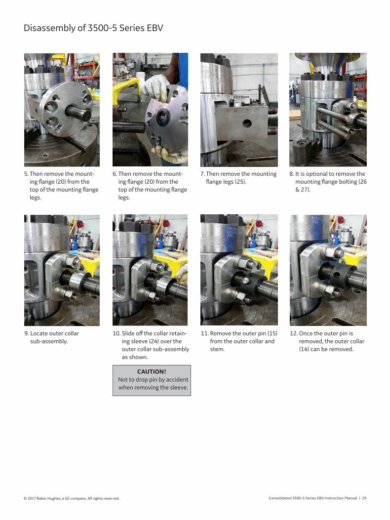
6. Then remove the mount-ing flange (20) from the top of the mounting flange legs.
5. Then remove the mount-ing flange (20) from the top of the mounting flange legs.
12. Once the outer pin is removed, the outer collar (14) can be removed.
11. Remove the outer pin (15) from the outer collar and stem.
10. Slide off the collar retain-ing sleeve (24) over the outer collar sub-assembly as shown.
9. Locate outer collar sub-assembly.
8. It is optional to remove the mounting flange bolting (26 & 27).
7. Then remove the mounting flange legs (25).
CAUTION!Not to drop pin by accident when removing the sleeve.

30 | BHGE © 2017 Baker Hughes, a GE company. All rights reserved.
13. Now, begin to loosen the packing gland nuts (13) and remove them.
18. You can remove the pack-ing gland studs (12) if you desire.
19. Loosen and remove all the discharge collar nuts (11B).
17. Remove the packing follower (08).
16. Remove the packing gland flange (07).
15. Remove both sets of gland springs.
14. Once the packing gland studs are removed, you can remove the gland springs (21).
20. Once all the discharge collar nuts are removed, prepare to lift off the discharge collar (02) using safety lifting devices.
Disassembly of 3500-5 Series EBV

Consolidated 3500-5 Series EBV Instruction Manual | 31© 2017 Baker Hughes, a GE company. All rights reserved.
Disassembly of 3500-5 Series EBV
23. Carefully remove the seat (3A). You may use the tapped holes on the seat to lift it off by installing some lifting bolts.
22. Locate the orifice (3F) part and remove it. Please mark the top and/or bot-tom side of the orifice.
21. Safely lift the discharge collar from the valve body (01).
25. Remove the gasket (04) from the body gasket pocket.
24. Lift up the seat from the valve.
26. Make sure the ball is in the closed position. Locate the ball (3B) and remove it from the body. You may need to slightly rotate the ball to engage it to the stem.
28. Stem is in correct posi-tion, you can remove the loader.
27. Rotate the stem, ¼ of a turn, 90 degrees count-er-clockwise to align the ‘flat” on the inner collar (16) so you can remove the loader (3C).

32 | BHGE © 2017 Baker Hughes, a GE company. All rights reserved.
33. Remove the inner collar over the stem.
32. Push the stem inwards towards the body cavity to gain access to the inner pin (17). Remove the inner pin from the inner collar and stem.
31. Remove the spacer ring (3E).
30. Remove the spiralwave spring (3D).
29. Loader part is removed.
36. Prepare the valve to accept new spare parts by cleaning away any residue of old, used parts. Photo above shows technician removing old gasket from body (01) part.
35. The packing bushing (10) does not need to be removed.
34. Remove stem (05) out-wards through body stem bore and thru packing bushing.
Disassembly of 3500-5 Series EBV
CAUTION!Careful not to drop pin when
removing the sleeve.
CAUTION!A rag can be placed inside the valve bore to prevent
any small loose items to be dropped and lost.

Consolidated 3500-5 Series EBV Instruction Manual | 33© 2017 Baker Hughes, a GE company. All rights reserved.
Reassembly of 3500-5 Series EBV
Reassembly
A� Lubrication 1. Acceptable lubricants are Molykote GN paste® and Sentry’s Twist® antisieze compound. 2. All threaded fasteners except pipe threads and tube fittings are to be lubricated. 3. Pipe threads must be sealed with pipe thread sealant or Teflon tape. Care must be taken not to get lubricant on any other
valve surfaces.
B� Tools Required 1. Stem nut wrench. 2. Two hooks for installation/removal of the ball. Two wire “S” hook about 6” (152.4 mm) to 8” (203.2mm) long (see Figure 3 to
shape wire). 3. Torque wrench or torque adjustable impact wrench. 4. Various size open x boxed end wrenches. 5. Screw drivers. 6. Wire cutter, stripper and lug crimper combination tool.
1. Clean away any residue of old, used parts. Photo above shows technician removing old gasket from body (01) part.
2. Insert the packing bushing (10) into packing area.
3. Insert stem (05) through body stem bore and through packing bushing.
4. Locate inner collar (16) and align the ‘flat’ side towards the right side of the stem position.
Notes: All parts to be thoroughly cleaned before assembly.All surfaces that are in contact with valve parts to be thoroughly cleaned.Refer to Nomenclature of parts on page 14 as reference.

34 | BHGE © 2017 Baker Hughes, a GE company. All rights reserved.
5. Install the inner collar over the stem and align the holes. Position the ‘flat’ of the inner collar to the right-side of the stem position.
6. Install the inner pin (17) through the inner collar and stem. You may need to pull up on the stem to pre-vent pin from disengaging..
7. Install the spacer ring (3E) with the ‘raised’ nose upwards.
8. Install the spiralwave spring (3D) on top of the spacer ring.
9. Pull the stem up and rotate the stem, ¼ of a turn, 90 degrees clockwise. The ‘flat’ side of the inner collar should be facing downwards or towards the spiralwave spring.
10. Place the loader (3C) on top of the spiralwave spring. The spherical side is assembled upwards.
11. Photo shows the assem-bly of the loader installed in position.
12. Rotate the stem, ¼ of a turn, 90 degrees count-er-clockwise and return it to the position shown in photo.
Reassembly of 3500-5 Series EBV
CAUTION!Careful not to drop pin
when removing the sleeve.
CAUTION!A rag can be placed inside the valve bore to prevent
any small loose items to be dropped and lost.

Consolidated 3500-5 Series EBV Instruction Manual | 35© 2017 Baker Hughes, a GE company. All rights reserved.
13. The ball’s (3B) stem slot will have identifying digits inscribed. Identify the numerical side, in this case, the number “3”, will be the ball side that will contact the loader.
14. Install the ball (3B) on top of the loader. You may need to slightly rotate the ball to engage it to the stem.
15. Install the gasket (04) into the body gasket pocket.
16. Locate the seat (3A) and position the spherical side towards the ball and position it on top of ball.
17. You can aligned the ‘tapped’ holes on the seat as shown.
18. Prepare all the discharge collar studs (11A) with some anti-seize lubri-cant.
19. Install the discharge collar studs into the body tapped holes.
20. Once all discharge collar studs are installed, it should resemble this photo.
Reassembly of 3500-5 Series EBV

36 | BHGE © 2017 Baker Hughes, a GE company. All rights reserved.
Figure 4 : Discharge Collar
Torquing Pattern
1
7
4
6 2
8
3
5
21. Locate the orifice (3F) part and position it on top of the seat.
22. Carefully lower the dis-charge collar (02) onto the body using the studs for guidance.
24. Once the discharge collar is safely resting on the body, prepare the top-side of the discharge col-lar studs with anti-seize lubricant.
25. Once all studs are lu-bricated, the discharge collar nuts (11B) can be installed on the studs. Torque each nut to its indicated value. Using Figure 4 as reference.
23. It is important to position the drain port (19) to-wards the bottom of the valve or 180 degrees from the stem position.
26. Install the packing rings (9A) over the stem and into the packing box.
27. You may need the pack-ing follower (08) to assist the packing rings into position.
Reassembly of 3500-5 Series EBV

Consolidated 3500-5 Series EBV Instruction Manual | 37© 2017 Baker Hughes, a GE company. All rights reserved.
28. Once the packing rings are installed, locate the anti-extrusion packing ring (9B). It will be the packing ring with a ‘split’.
29. Install the anti-extrusion packing ring on top of the packing rings. You may use the packing follower to assist you to compress it. Lubricate the packing gland stud with anti-seize and install it into the body tapped holes.
31. Install the packing gland flange (07) over the pack-ing follower.
30. Locate the gland springs (21) and assemble them over the packing gland stud and on top of the packing gland flange.
32. Locate the gland springs (21) and assemble them over the packing gland stud and on top of the packing gland flange.
33. Each side of the packing gland stud should have equal number of gland springs.
34. Lubricate the top of the packing gland studs with anti-seize and install packing gland nuts (13). Torque the packing gland nuts to the specified torque value.
35. Locate and install the outer collar (14) and align the hole with the stem hole. It is important to position the side with the ‘lip’ towards the bottom or packing gland flange.
Reassembly of 3500-5 Series EBV

38 | BHGE © 2017 Baker Hughes, a GE company. All rights reserved.
36. Install the outer pin (15) through the outer collar and stem.
37. Slide the collar retaining sleeve (24) over the out-er collar sub-assembly as shown.
38. The collar retaining sleeve should engage the ‘lip’ of the outer collar.
39. Lubricate the mounting flange studs (27) with an-ti-seize and install them into the body mounting flange tapped holes.
40. Locate and install the mounting legs (26).
41. It is important to note the side with longer distance from bottom to hole position is facing the valve body.
42. Install the guide bearing (06) onto the bottom side of the mounting flange (25).
43. Then install the mount-ing flange on top of the mounting flange legs.
Reassembly of 3500-5 Series EBV
Consolidated 3500-5 Series EBV Instruction Manual | 39© 2017 Baker Hughes, a GE company. All rights reserved.
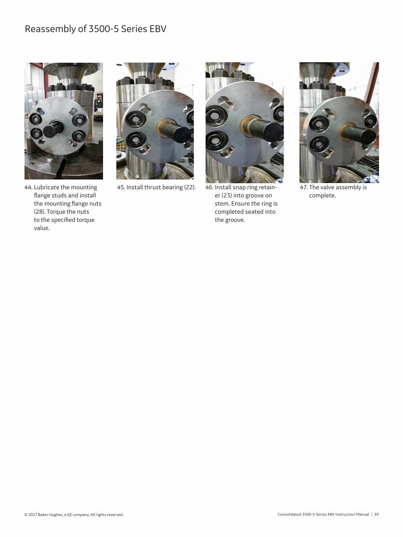
46. Install snap ring retain-er (23) into groove on stem. Ensure the ring is completed seated into the groove.
47. The valve assembly is complete.
44. Lubricate the mounting flange studs and install the mounting flange nuts (28). Torque the nuts to the specified torque value.
45. Install thrust bearing (22).
Reassembly of 3500-5 Series EBV

40 | BHGE © 2017 Baker Hughes, a GE company. All rights reserved.
Start-up of the System1� Prior to Start-up Checks
a. The isolation valve can remain in the open or closed position. Please refer to your local operating requirements.
b. Turn on the power and set the MVC-5000 digital controller to AUTO mode via either the local touchscreen, switch box, or remote panel. The MVC-5000 display will illuminate when power is applied.
c. Switch the MVC-5000 to OPEN mode via either the local touch screen, switch box, or remote panel. Observe to verify that the valve rotated to the OPEN position. The MVC-5000 display and remote panel will also indicate valve position.
d. Switch the MVC-5000 back to AUTO mode via either the local touchscreen, switch box, or remote panel. The valve should close, and the MVC-5000/Remote Panel will display the valve position.
Setting and Testing
Before disassembling the valve, ensure there is no media pressure in
the vessel�
Wear necessary protective equipment
to prevent possible injury�
40 | GE Oil & Gas © 2017 General Electric Company. All rights reserved.
Start-up of the System1. Prior to Start Up Checks
a. The isolation valve can remain in the open or closed position. Please refer to your local operating requirements.
b. Turn on the power and set the MVC-5000 digital controller to AUTO mode via either the local touchscreen, switch box, or remote panel. The MVC-5000 display will illuminate when power is applied.
c. Switch the MVC-5000 to OPEN mode via either the local touch screen, switch box, or remote panel. Observe to verify that the valve rotated to the OPEN position. The MVC-5000 display and remote panel will also indicate valve position.
d. Switch the MVC-5000 back to AUTO mode via either the local touchscreen, switch box, or remote panel. The valve should close, and the MVC-5000/Remote Panel will display the valve position.
Logic decision during AUTO mode
Logic decision when valve is in OPEN mode
Setting and Testing
Before disassembling the valve, ensure there is no
media pressure in the vessel.
Wear necessary protective equipment to prevent
possible injury.
AUTOMode is selected
Valve initial position: closed
System < Set
OPENMode is selected
Valve remainsclosed
Actuator opens the valve
System > Reseat
System >= Set
Valve remainsopen
Valve remainsopen
System >= Set
Valve is venting (During OPEN Mode)
Valve opens
Press AUTO to command to
CLOSE
System <= Reseat
System < Set
Valve closes
Valve closes

Consolidated 3500-5 Series EBV Instruction Manual | 41© 2017 Baker Hughes, a GE company. All rights reserved.
The setting of the Electromatic Ball Valve should be carried out by simulating system pressure to the pressure transducer.The figure below illustrates the equipment and instruments required to isolate the pressure transducer and apply external pressure. The following steps allow the verification of controller, actuator, and valve actuation when system pressure exceeds the nameplate pressure:
a. The EBV isolation valve shall remain in the closed position to avoid venting the system.
b. Turn on power and set the MVC-5000 digital controller to AUTO mode via the local touchscreen. The MVC-5000 display will illuminate when power is applied.
c. Verify the EBV is in the closed position. The local digital display of the controller should read “VALVE CLOSED.”
d. Close the manifold block valve to isolate the pressure transducer {1}
e. System pressure can be present in the siphon line and block/bleed manifold, take precaution to slowly bleed system pressure by opening the manifold bleed valve {2}. Wear necessary protective equipment to prevent possible injury.Opening bleed valve can expose high temperature gas or liquid.
SET WITH THE PRESSURE TRANSDUCER DISCONNECTED
Once the system pressure has been vented an alternative method to set/calibrate the controller is to disconnect the pressure transducer from the tubing/piping and connect it to a fixture to apply pressure. The following method is advised when pressure is present behind the block valve or the applied pressure may result in damage to the valve.
f. Connect a calibration hydraulic hand pump with a calibrated gauge to the manifold bleed valve exhaust port {2}. Distilled water is the recommended fluid for the hydraulic pump. Avoid using oil based hydraulic fluid.
g. Verify the set pressure in the valve nameplate matches to the set pressure in the MVC-5000.
h. Apply external pressure using the hydraulic pump to increase the system pressure by 200 psi (10 to 20 bar) increments not to exceed the valve set pressure. Verify the pressure reading in calibrated gauged matches the system pressure reading in the MVC-5000 controller (pressure reading from the pressure transducer). The EBV should remain the closed position on this step.
2� Setting of the EBV and Digital Controller
Setting and Testing
Pressure Transducer
Siphon
Bleed Valve
Block Valve
Hydraulic Pump
Pressure sensing connection should be located at least 8 to 10 pipe diameters upstream from the EBV
1
2
Calibrated Gauge
Required equipmentinstrument to set controller
Manifold required to isolate and apply external pressure
Recommended connections provided by End User
i. In this step the set pressure of the controller is verified by slowly increasing the system pressure to exceed the set pressure. Actuator rotation (actuation to open) can be verified in this step as well. Once the controller actuates the valve, maintain system pressure above set pressure. Verify the pressure reading in calibrated gauged matches the system pressure reading in the MVC-5000 controller. The controller local digital display should illuminate to read “VALVE OPENING”, followed by “VALVE OPEN” when the valve reaches the travel limit.
j. In this step the reseat pressure of the controller is verified by slowly relieving the hydraulic pressure from the pump to below set pressure. Once the controller actuates the valve, maintain system pressure below set pressure. Verify the pressure reading in calibrated gauged matches the system pressure reading in the MVC-5000 controller. The controller local digital display should illuminate to read “VALVE CLOSING”, followed by “VALVE CLOSED” when the valve reaches the travel limit.
CAUTION!Make sure that no pressure is in the valve prior to setting. If equipped with an isolation valve, close the isolation valve.
If not equipped with an isolation valve, the unit must be shut down prior to setting.

42 | BHGE © 2017 Baker Hughes, a GE company. All rights reserved.
Setting and Testing
k. Relieve all the hydraulic pressure from the pump and disconnect the apparatus from the manifold bleed valve.
l. Allow the fluid to drain from the manifold and close the manifold bleed valve {2}.
m. Open the manifold block valve {1} and verify pressure reading from the digital controller display.
Pressure transducer calibration can be carried out by following the same steps described above. Calibration should be done by a qualified technician. Follow the recommended controller calibration steps defined by the manufacturer’s IOM.
http://mightyinstruments�com/images/datasheets/MVC-5000PARV%20-%20IOM%202�pdf
3. System Start-up
a. If the Electromatic Ball Valve is equipped with an isolation valve, the isolation valve can remain in the open or closed position. Please refer to your local operating requirements during system start-up.
4. Adjusting the Set Pressure and Blowdown
a. Set pressure and blowdown is set at factory or by authorized personnel for ASME Section I valve and controllers.
b. Non- ASME controller set point and blowdown can be adjusted by opening the controller front window cover and manually enter the pressure values into the menu (touchscreen).
5. Minimum Blowdown setting
6. Hydrostatic Testing
When conducting a hydrostatic test involving the Electromatic Ball valve, the sensing line to the pressure transducer should be disconnected, or isolated, to prevent damage to the pressure transducer. Be sure to reconnect the sensing line after the hydrostatic test is completed. The hydrostatic test may be conducted with the Isolating Gate Valve closed, unless the Electromatic* Ball Valve is to be subjected to the hydrostatic test, In such case, either the isolating Gate Valve, or the By-Pass Valve, should be opened.
Table 3: Recommended Blowdown for ASME and Non-ASME Applications
Seat Point Minimum Blowdown
All Pressures 2.0% of Set Pressure
Consolidated 3500-5 Series EBV Instruction Manual | 43© 2017 Baker Hughes, a GE company. All rights reserved.
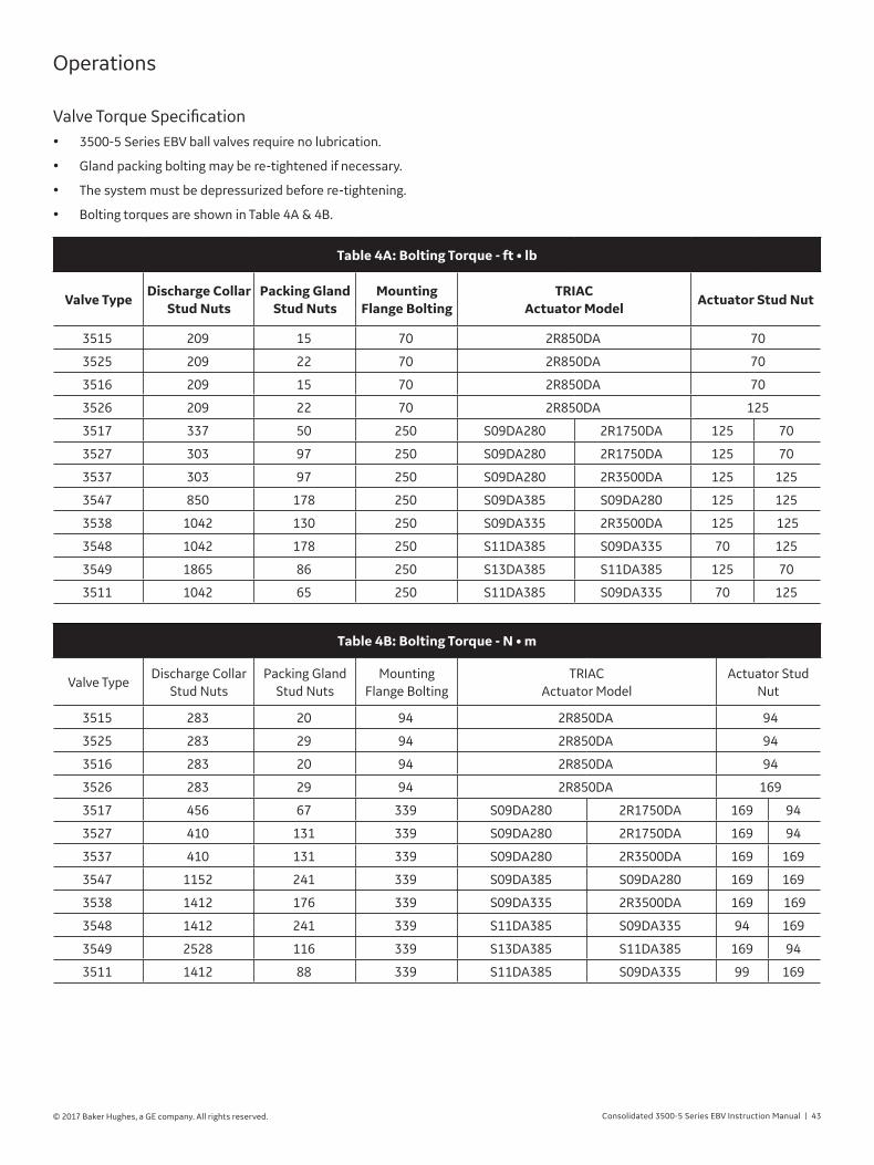
Operations
Valve Torque Specification• 3500-5 Series EBV ball valves require no lubrication.
• Gland packing bolting may be re-tightened if necessary.
• The system must be depressurized before re-tightening.
• Bolting torques are shown in Table 4A & 4B.
Table 4A: Bolting Torque - ft • lb
Valve TypeDischarge Collar
Stud NutsPacking Gland
Stud NutsMounting
Flange BoltingTRIAC
Actuator ModelActuator Stud Nut
3515 209 15 70 2R850DA 70
3525 209 22 70 2R850DA 70
3516 209 15 70 2R850DA 70
3526 209 22 70 2R850DA 125
3517 337 50 250 S09DA280 2R1750DA 125 70
3527 303 97 250 S09DA280 2R1750DA 125 70
3537 303 97 250 S09DA280 2R3500DA 125 125
3547 850 178 250 S09DA385 S09DA280 125 125
3538 1042 130 250 S09DA335 2R3500DA 125 125
3548 1042 178 250 S11DA385 S09DA335 70 125
3549 1865 86 250 S13DA385 S11DA385 125 70
3511 1042 65 250 S11DA385 S09DA335 70 125
Table 4B: Bolting Torque - N • m
Valve TypeDischarge Collar
Stud NutsPacking Gland
Stud NutsMounting
Flange BoltingTRIAC
Actuator ModelActuator Stud
Nut
3515 283 20 94 2R850DA 94
3525 283 29 94 2R850DA 94
3516 283 20 94 2R850DA 94
3526 283 29 94 2R850DA 169
3517 456 67 339 S09DA280 2R1750DA 169 94
3527 410 131 339 S09DA280 2R1750DA 169 94
3537 410 131 339 S09DA280 2R3500DA 169 169
3547 1152 241 339 S09DA385 S09DA280 169 169
3538 1412 176 339 S09DA335 2R3500DA 169 169
3548 1412 241 339 S11DA385 S09DA335 94 169
3549 2528 116 339 S13DA385 S11DA385 169 94
3511 1412 88 339 S11DA385 S09DA335 99 169

44 | BHGE © 2017 Baker Hughes, a GE company. All rights reserved.
Open/Close• 3500-5 Series EBV ball valves are operated clockwise to
close and counter-clockwise to open.
Valve position indication• A scribe mark on the side of the stem indicate whether the
valve is open or closed as shown below. The scribe marks are in line with the key on both sides of the stem and in line with.
• The punch mark on top of the stem indicates the primary sealing side of the ball when the valve is in closed position.
Punchmark Punch
mark
High Pressure end High Pressure end
Scribe mark
Valve Open Valve Closed
Scribe mark
Counter-Clockwiseto Open.
Clockwise to Close.
Scribe mark
Operations (Cont’d)

Consolidated 3500-5 Series EBV Instruction Manual | 45© 2017 Baker Hughes, a GE company. All rights reserved.
Quick Reference Guide
1� Verify Operating Position
Open and close the valve to ensure the ball position is identified and matches the operator position indicators.
Note: If the valve does not have an operator installed, you must install the appropriate operator to open and close the valve prior to valve installation.
If the valve assembly includes a mounted actuator, the actuator must not be re-oriented without removal from the valve. This prevents 180 degree rotation of the ball and assures the mate-lapped ball and seat surfaces match.
2� Identify Sealing Direction
The preferred direction of flow is from the higher to lower pressure end, when the valve is closed. For normal installation, the valve should be installed with the marked
Pressure End positioned toward the higher pressure against the valve when in the closed position.
However, in certain conditions, proper operation may require the sealing seat be positioned opposite the flow direction. For these circumstances, the valve should be installed with the marked Pressure End positioned toward the lower pressure against the valve when in the closed position.
3� Position Valve in Piping
Verify that the valve and operator orientation is correct. Verify that the valve is in the open position to prevent any damage to the ball surface from debris or weld splatter.
Note: Any “spring return to close” actuator must be pressurized or manually opened as required to keep the valve open during welding.
Position the valve in line with mating piping or flanges.
Note: Support or lift as required, using lifting lugs or nylon straps around the valve body. Do not lift or support by the actuator alone.
4� Secure Valve in Place Flanged
Install the flange gaskets and bolting. Tighten per customer requirements.
CAUTION: Current flow through valve can damage the ball or seat
coating and cause valve leakage.
Note: Use the welding ground strap on the same end of the valve as welding to prevent current flow through valve.
Weld the valve in-line using ASME Section IX approved weld procedures. Weld the circumference of the weld evenly to minimize distortion.
The temperature of the main body section of the valve should not exceed the rated valve temperature. Actuator temperature should not exceed 250°F (121°C). Cool the valve or actuator as required.
5� Post-Weld Stress Relief
Preheat and post-weld stress relief should be carried out per ASME Section IX and ASME B31.1.
Heat input to the valve during stress relief is to be minimized and monitored. The temperature of the main body section of the valve should not exceed the rated valve temperature.
Actuator temperature should not exceed 250°F (121°C)�
Place the heating coils as close to weld as possible and keep the valve surfaces clear to allow maximum heat dissipation from the valve.
6� Verify Operation
Inspect the condition of the valve and operator for proper orien-tation and alignment.
Open and close the valve several times to ensure smooth oper-ation, noting any differences between before and after installa-tion.

46 | BHGE © 2017 Baker Hughes, a GE company. All rights reserved.
Maintenance
CAUTION!IT IS EXTREMELY IMPORTANT TO FOLLOW THESE STEPS TO ENSURE MAXIMUM VALVE PERFORMANCE.
THIS WILL AFFECT THE VALVE WARRANTY.
CAUTION! IF BOLTING TORQUE IS LOWER THAN SPECIFIED VALUES ON TABLE 2, RE-TORQUE BOLTING AS NECESSARY.
THIS WILL AFFECT THE VALVE WARRANTY.
Verify Bolting TorqueAfter the first exposure to elevated temperature and the valve has completely cooled-down, verify bolting torque at these locations:
1. Packing gland flange.
2. Body to end connection.
3. Actuator to valve mounting (if present). Check the bolting at these same locations periodically.
Actuator LubricationKeep pneumatic actuators fully lubricated according to actuator manufacturer's specifications.
2
1
3

Consolidated 3500-5 Series EBV Instruction Manual | 47© 2017 Baker Hughes, a GE company. All rights reserved.
Troubleshooting
Table 5 is provided as a guideline to be followed should the actuator fail to function properly. If all the steps listed in Table ? are followed and the actuator still does not function, the factory should be consulted.
Note: The valve should be isolated from system pressure while trouble shooting of the actuation system. Accidental actuation of the valve could occur.
Table 5: Actuation System Trouble Shooting
Problem Possible Cause Corrective Action
Valve will not open when over pressure occurs
1. Pressure transducer wires are connected to wrong terminal in the MVC-5000.
Verify pressure transducer wires are connected to correct terminal connection of the controller.
2. No air supply pressure to the solenoid valve or poppet valves.
Re-establish air supply pressure to the solenoid valves or poppet valves.
3. Solenoid valve coil burnt out.Check solenoid coil,Burnt coil - Replace coil.No-Go to possible cause 4
4. Loss of electrical power supply.Check voltage,No voltage – Re-establish electric power.Has voltage – Go to possible cause 6
5. Damaged On/OFF/AUTO selector switch in con-troller switchbox.
Check continuity of contacts,No continuity – Replace switch,Has continuity – Go to possible cause 6
6. Pressure transducer is not calibrated, MVC-5000 is not calibrated, or transducer is faulty.
Calibrate the transducer zero and span, calibrate the MVC-5000 analog input, or replace the pressure transducer.
7. MVC-5000 relay failure. Replace the MVC-5000 terminal board.
8. MVC-5000 is in OFF mode. Switch to AUTO mode.
Valve will not open with MVC-5000 controller
selection in OPEN mode or reclose when in AUTO-
MATIC
1. No air supply pressure to the solenoid valve or poppet valves.
Re-establish air supply pressure to the solenoid valves
2. Solenoid valve coil burnt out.Check solenoid coil,Burnt Coil – Replace coil,No – Go to possible cause 3.
3. Lose of electric power supply.Check voltage,No voltage – Re-establish electric power,Has Voltage – Go to possible cause 4.
4. S1, S2 in actuator limit switch not properly set or has failed.
Check continuity between switch C and NO terminals.No Continuity – Replace switch,Has continuity – Go to possible cause 6.Check continuity of contacts,No continuity – Replace switch,Has continuity – Go to possible cause 6
6. MVC-5000 relay failure. Replace the MVC-5000 terminal board.
7. Wiring or terminal plug failure.Check all wire and terminal connections.Replace as required
After open command, valve closes immediately
without control
1. Pilot air is not reaching the pilot valve. Clean or replace check valve in the air supply to the actuator
2. Switchbox selection is in AUTO.Move the switchbox selection to the OFF position for Non-ASME or OPEN position for ASME
Pulsating actuation 1. Pilot air is intermittently reaching the pilot valve. Clean or replace check valve in the air supply to the actuator

bhge.com*Denotes a trademark of Baker Hughes, a GE company, LLC.
Other company names and product names used in this document are the registered trademarks or trademarks of their respective owners.
© 2017 Baker Hughes, a GE company, LLC – All rights reserved.
BHGE reserves the right to make changes in specifications and features shown herein, or discontinue the product described at any time without notice or obligation. Contact your BHGE representative for the most current information. The BHGE logo is a trademark of Baker Hughes, a GE company, LLC. Baker Hughes, a GE company, the GE monogram, and Consolidated are trademarks of the General Electric Company and Baker Hughes, a GE company, LLC.
GEA32854D 11/2017
AUSTRALIABrisbane:Phone: +61-7-3001-4319Fax: +61-7-3001-4399
Perth:Phone: +61-8-6595-7018Fax: +61-8-6595-7299
Melbourne:Phone: +61-3-8807-6002Fax : +61-3-8807-6577
BELGIUMPhone: +32-2-344-0970Fax: +32-2-344-1123
BRAZILPhone: +55-19-2104-6900
CHINAPhone: +86-10-5738-8888Fax: +86-10-5918-9707
FRANCECourbevoiePhone: +33-1-4904-9000Fax: +33-1-4904-9010
GERMANYRatingenPhone: +49-2102-108-0Fax: +49-2102-108-111
INDIAMumbaiPhone: +91-22-8354790Fax: +91-22-8354791
New DelhiPhone: +91-11-2-6164175Fax: +91-11-5-1659635
ITALYPhone: +39-081-7892-111Fax: +39-081-7892-208
JAPANTokyo Phone: +81-03-6871-9008Fax: +81-03-6890-4620
KOREAPhone: +82-2-2274-0748Fax: +82-2-2274-0794
MALAYSIAPhone: +60-3-2161-0322Fax: +60-3-2163-6312
MEXICOPhone: +52-55-3640-5060
THE NETHERLANDSPhone: +31-15-3808666
RUSSIAVeliky NovgorodPhone: +7-8162-55-7898Fax: +7-8162-55-7921MoscowPhone: +7 495-585-1276Fax: +7 495-585-1279
SAUDI ARABIAPhone: +966-3-341-0278Fax: +966-3-341-7624
SINGAPOREPhone: +65-6861-6100Fax: +65-6861-7172
SOUTH AFRICAPhone: +27-11-452-1550Fax: +27-11-452-6542
SOUTH & CENTRAL AMERICA AND THE CARIBBEANPhone: +55-12-2134-1201Fax: +55-12-2134-1238
SPAINPhone: +34-93-652-6430Fax: +34-93-652-6444
UNITED ARAB EMIRATESPhone: +971-4-8991-777Fax: +971-4-8991-778
UNITED KINGDOMBracknellPhone: +44-1344-460-500Fax: +44-1344-460-537
SkelmersdalePhone: +44-1695-526-00Fax: +44-1695-526-01
UNITED STATESJacksonville, FloridaPhone: +1-904-570-3409
Deer Park, TexasPhone: +1-281-884-1000Fax: +1-281-884-1010
Houston, TexasPhone: +1-281-671-1640Fax: +1-281-671-1735
DIRECT SALES OFFICE LOCATIONS