Electromagnetic tracking of needle intervention for sacral nerve stimulation using the image-guided...
6
INTERNATIONAL JOURNAL OF PRECISION ENGINEERING AND MANUFACTURING Vol. 14, No. 11, pp. 2015-2020 NOVEMBER 2013 / 2015 © KSPE and Springer 2013 Electromagnetic Tracking of Needle Intervention for Sacral Nerve Stimulation Using the Image-Guided Surgery Toolkit (IGSTK) Youngjin Na 1 , Jong-Mo Seo 2,3 , and Jung Kim 1,# 1 Department of Mechanical Engineering, KAIST, 291 Daehak-ro, Yuseong-gu, Daejeon, Republic of Korea, 305-701 2 Department of Ophthalmology, School of Medicine, Seoul National University, Seoul, Republic of Korea 3 Electrical Engineering and Computer Science, Seoul National University College of Engineering, Seoul, Republic of Korea # Corresponding Author / E-mail: [email protected], TEL: +82-42-350-3231, FAX: +82-42-350-5230 KEYWORDS: Sacral nerve stimulation, Electromagnetic navigation, Needle insertion Sacral nerve stimulation (SNS) is a therapeutic medical procedure that stimulates the sacral nerve using an electrode inserted near the sacral nerve to treat the conditions of overactive bladder and fecal incontinence. The primary challenge in the SNS procedure is that the physician inserts a needle to place an electrode through the narrow structure of the sacrum while relying on fluoroscopic images. We developed a navigation system which relies on an off-the-shelf electromagnetic tracking device, preoperative CT images, and a graphical user interface for needle insertion. Subjects inserted the needle into targets in a free metallic environment and in a surgical environment with a sacral phantom model. The mean registration error in four trials was 0.90±0.081 mm in the free metallic environment and 1.16±0.49 mm in the surgical environment. The mean user error (UE) between the needle tip position and a target was 5.08±1.27 mm in the free metallic environment and 4.26±2.87 mm in the surgical environment. We believe that our navigation system has potential to improve clinical sacral nerve stimulation treatment considerably. To support clinical application of this method, several remaining issues pertaining to the developed navigation system in an in vivo environment must be resolved. Manuscript received: January 6, 2013 / Accepted: September 2, 2013 1. Introduction Sacral nerve stimulation (SNS) is a therapeutic medical procedure to stimulate the sacral nerve using an electrode inserted near the sacral nerve for overactive bladder and fecal incontinence1. 1 The physician inserts a needle via the sacral foramen to place an electrode. The physician plans an insertion path to approach the sacral nerve and tracks the needle tip position relying on fluoroscopic images from a C- arm device. Electrode insertion near the sacral nerve is a challenging technique because needle insertion highly relies on the physician's experience and the ability to reconstruct 3D virtual images from 2D fluoroscopic images of the patient. The physician imagines a 3D structure based on 2D fluoroscopic images, which cannot provide the clear images of the sacrum. 2 Therefore, the physician requires the fluoroscopic images repeatedly, and fluoroscopically guided procedures induce radiation exposure to the physician and the patient. The short-term risk is related to skin injury and the long-term effects can lead to infection. 3 The physician plans the insertion path through the sacral foramen instead of the sacral nerve because the sacral nerve is located beneath the sacral foramen and not displayed in the fluoroscopic image. As a result, the needle tip position is confirmed based on the relative distance between the sacral foramen and the needle tip in fluoroscopic images or observations of muscle activation stimulated by an electrode. 4 Computer-assisted navigation can be a solution to improve the precision of needle insertion. These systems provide the real-time needle tip position with preoperative images and have several advantages, as they shorten preoperative learning period, enable minimally invasive procedures, and provide a quantitative comparison. 5 Specifically, many studies have been conducted regarding computer-assisted needle insertion because needle insertion is one of the most common procedures for biopsies, thermal ablation, and radiofrequency ablation. Previously developed systems for needle insertion have focused on accuracy in clinical trials. Banovac et al. tested a navigation system with an electromagnetic tracking device for targeting in a physiologic phantom and in a swine model. 6,7 There was no difference in the planning time, needle insertion accuracy or the procedure time between experienced DOI: 10.1007/s12541-013-0274-9
Transcript of Electromagnetic tracking of needle intervention for sacral nerve stimulation using the image-guided...
INTERNATIONAL JOURNAL OF PRECISION ENGINEERING AND MANUFACTURING Vol. 14, No. 11, pp. 2015-2020 NOVEMBER 2013 / 2015
© KSPE and Springer 2013
Electromagnetic Tracking of Needle Intervention forSacral Nerve Stimulation Using the Image-GuidedSurgery Toolkit (IGSTK)
Youngjin Na1, Jong-Mo Seo2,3, and Jung Kim1,#
1 Department of Mechanical Engineering, KAIST, 291 Daehak-ro, Yuseong-gu, Daejeon, Republic of Korea, 305-7012 Department of Ophthalmology, School of Medicine, Seoul National University, Seoul, Republic of Korea
3 Electrical Engineering and Computer Science, Seoul National University College of Engineering, Seoul, Republic of Korea # Corresponding Author / E-mail: [email protected], TEL: +82-42-350-3231, FAX: +82-42-350-5230
KEYWORDS: Sacral nerve stimulation, Electromagnetic navigation, Needle insertion
Sacral nerve stimulation (SNS) is a therapeutic medical procedure that stimulates the sacral nerve using an electrode inserted near
the sacral nerve to treat the conditions of overactive bladder and fecal incontinence. The primary challenge in the SNS procedure
is that the physician inserts a needle to place an electrode through the narrow structure of the sacrum while relying on fluoroscopic
images. We developed a navigation system which relies on an off-the-shelf electromagnetic tracking device, preoperative CT images,
and a graphical user interface for needle insertion. Subjects inserted the needle into targets in a free metallic environment and in a
surgical environment with a sacral phantom model. The mean registration error in four trials was 0.90±0.081 mm in the free metallic
environment and 1.16±0.49 mm in the surgical environment. The mean user error (UE) between the needle tip position and a target
was 5.08±1.27 mm in the free metallic environment and 4.26±2.87 mm in the surgical environment. We believe that our navigation
system has potential to improve clinical sacral nerve stimulation treatment considerably. To support clinical application of this
method, several remaining issues pertaining to the developed navigation system in an in vivo environment must be resolved.
Manuscript received: January 6, 2013 / Accepted: September 2, 2013
1. Introduction
Sacral nerve stimulation (SNS) is a therapeutic medical procedure
to stimulate the sacral nerve using an electrode inserted near the sacral
nerve for overactive bladder and fecal incontinence1.1 The physician
inserts a needle via the sacral foramen to place an electrode. The
physician plans an insertion path to approach the sacral nerve and
tracks the needle tip position relying on fluoroscopic images from a C-
arm device. Electrode insertion near the sacral nerve is a challenging
technique because needle insertion highly relies on the physician's
experience and the ability to reconstruct 3D virtual images from 2D
fluoroscopic images of the patient. The physician imagines a 3D structure
based on 2D fluoroscopic images, which cannot provide the clear
images of the sacrum.2 Therefore, the physician requires the fluoroscopic
images repeatedly, and fluoroscopically guided procedures induce
radiation exposure to the physician and the patient. The short-term risk
is related to skin injury and the long-term effects can lead to infection.3
The physician plans the insertion path through the sacral foramen
instead of the sacral nerve because the sacral nerve is located beneath
the sacral foramen and not displayed in the fluoroscopic image. As a
result, the needle tip position is confirmed based on the relative distance
between the sacral foramen and the needle tip in fluoroscopic images
or observations of muscle activation stimulated by an electrode.4
Computer-assisted navigation can be a solution to improve the
precision of needle insertion. These systems provide the real-time needle
tip position with preoperative images and have several advantages, as
they shorten preoperative learning period, enable minimally invasive
procedures, and provide a quantitative comparison.5 Specifically, many
studies have been conducted regarding computer-assisted needle insertion
because needle insertion is one of the most common procedures for
biopsies, thermal ablation, and radiofrequency ablation. Previously
developed systems for needle insertion have focused on accuracy in
clinical trials. Banovac et al. tested a navigation system with an
electromagnetic tracking device for targeting in a physiologic phantom
and in a swine model.6,7 There was no difference in the planning time,
needle insertion accuracy or the procedure time between experienced
DOI: 10.1007/s12541-013-0274-9
2016 / NOVEMBER 2013 INTERNATIONAL JOURNAL OF PRECISION ENGINEERING AND MANUFACTURING Vol. 14, No. 11
subjects and inexperienced subjects. Maier-Hein et al. assessed the
accuracy of needle insertion for CT-guided radiofrequency ablation in
vivo.8 In their results, non-experts achieved better performance than
experts. Cleary et al. developed an image-guided surgery toolkit (IGSTK),
which is a high-level open-source software toolkit, for researchers to
develop image-guided surgery applications.9 Yaniv et al. presented three
navigation systems for needle interventional procedures (vertebroplasty,
RF ablation of lung tumor, and lung biopsy) using IGSTK.10 In the three
navigation systems, they used an electromagnetic tracking device and
3-D images with preoperative CT images for visual feedback in clinical
cases. Electromagnetic tracking devices are used in many applications
to track the instrument position because they have advantages over an
optical tracking device, including no line-of-sight and no requirement
to consider needle deflection.11 The tracked sensor is easy to use with
conventional surgical instruments because the sensor can be easily
embedded into an instrument tip. However, the accuracy of an
electromagnetic tracking device undergoes distortion if metallic objects
or electrical devices are near the field generator and the sensor. Many
researchers have investigated methods to estimate the tracking error
and have worked to develop a compensation method to offset the error
of electromagnetic tracking devices.12-15
We proposed a navigation system to replace with the fluoroscopic
images in SNS. Based on the IGSTK, we added functions for SNS
procedures and tested the feasibility of the system in a surgical
environment. The proposed navigation system used an off-the-shelf
electromagnetic tracking device to track the needle tip position and
preoperative CT images for visual feedback. The accuracy of the
electromagnetic tracking device was measured in a free metallic
environment and in a surgical environment. We also tested it with a
phantom model and measured the user error, which is the distance
between a target point and the needle tip in an image coordinate.
2. Navigation System
2.1 Sacral Nerve Stimulation (SNS) procedures
It is important to determine an insertion point and confirm the
needle tip position. In the conventional method, the physician takes a
fluoroscopic image of the needle and the patient’s body from a C-arm
device and plans the needle insertion path. The physician predicts the
sacral foramen point as shown in Fig. 1 and then selects an insertion
point approximately 1.5 cm away from the sacral foramen center toward
the cranial direction and the insertion angle is about 45 degrees.16 The
third sacral (S3) nerve was a target nerve in Fig. 1. Therefore the
physician inserted the needle through the S3 foramen position as shown
in Fig. 2. Preoperative testing, known as a percutaneous nerve evaluation,
is a process of inserting a temporary stimulation electrode which is
connected to an external pulse generator. It generates a signal to stimulate
a nearby sacral nerve. If this neuromodulation has positive results for
the patient, a permanent implantation is performed. The temporary
stimulation electrode is replaced by the permanent stimulation electrode
and a generator is implanted in a subcutaneous pocket in the outer
quadrant of the buttock or the lower abdomen.
2.2 Electromagnetic tracking device
The developed navigation system uses an aurora electromagnetic
tracking device (Northern Digital Inc., Waterloo, ON, Canada) to track
the needle tip position. IGSTK provides in the form of classes for the
aurora device. The aurora device consists of a field generator, a control
unit, a sensor interface unit, and a sensor coil. The position and
orientation of the sensor coil are estimated by the induced voltage of
the sensor coil based on a field generator. The sensor coils, which
consist of three perpendicular coils embedded into an 18-gauge needle
(Aurora needle, 2-Part, 18G/150 mm, Chiba), coincide with the needle
axis. The tracking data provides three instances of position data and
two instances of orientation data (5DOF). For an accurate measurement,
the offset between the needle tip and the sensor location is considered
by means of pivot calibration.17
2.3 Registration
The rigid paired-point registration included in the IGSTK coincides
with the patient coordinate and the image coordinate based on the
position of each fiducial marker.18 The positions of the fiducial markers
in image coordinate (di) were recorded by manual selection in the
interface, while the positions of fiducial markers in patient coordinate
(mi) were measured by tapping with the needle tip. The rotational and
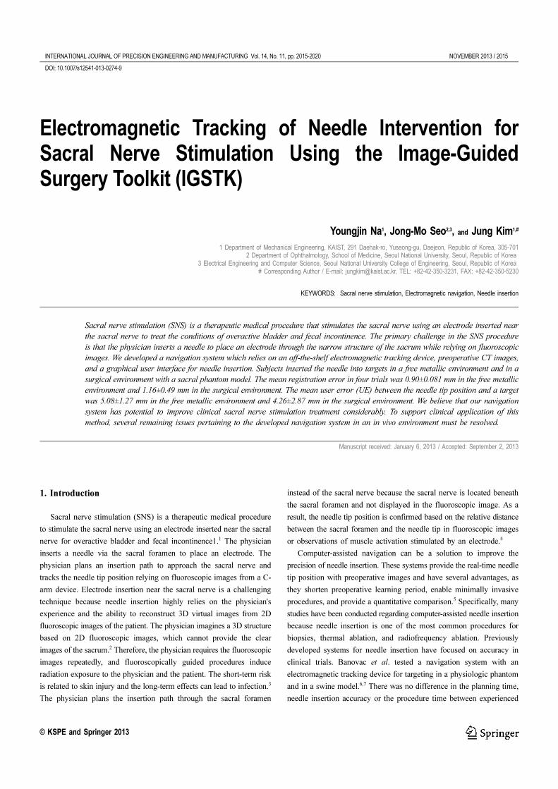
Fig. 1 Fluoroscopic images from the C-arm are used in SNS - Location
of sacral foramen was predicted lateral to the junction of the midline
and the lateral line in the top view (a) An inserted electrode was
displayed in the sagittal view (b) Supplementary images are available in
the literature16
Fig. 2 Location of third sacral (S3) foramen and needle insertion in
SNS (sagittal view)
INTERNATIONAL JOURNAL OF PRECISION ENGINEERING AND MANUFACTURING Vol. 14, No. 11 NOVEMBER 2013 / 2017
translational components between the two coordinate systems are
calculated using a least squares method to determine the rigid-body
registration. Two points sets {di} and {mi}, are related according to the
following equation:
(1)
Where and are point vectors in image coordinate and point vector
in patient coordinate, respectively. R is 3×3 rotation matrix. t is a
translation vector and vi is a noise vector. i is number of fiducial
markers.
R and t were optimized values by the least squares error criterion.
The fiducial registration error (FRE) is a useful equation for confirming
the rigidity of the registration.19 The FRE describes the distance error
at the fiducial markers between the two coordinates used in the
registration, as shown in Eq. (2)
(2)
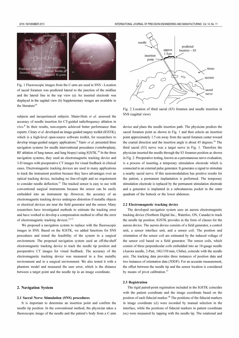
2.4 Graphic User Interface
Four views are reformatted from the CT images. Three of these are
the axial, sagittal, and coronal view. The fourth view is a combination
of the axial and sagittal views to provide three-dimensional information.
The field of view is selected based on the position of the needle tip.
The user can select an entry point (blue dot) and a target point (red dot)
to plan an insertion path, which can be modified during the operation.
The estimated path is displayed to predict the next needle position if the
needle is inserted along the current angle and the ensuing needle
position. The planned path (green line) is displayed on four views of an
interface along with the estimated path (white line), as shown in Fig.
3. The alignment of the planned path and the estimated path are the
recommend case to secure accuracy during the needle insertion process.
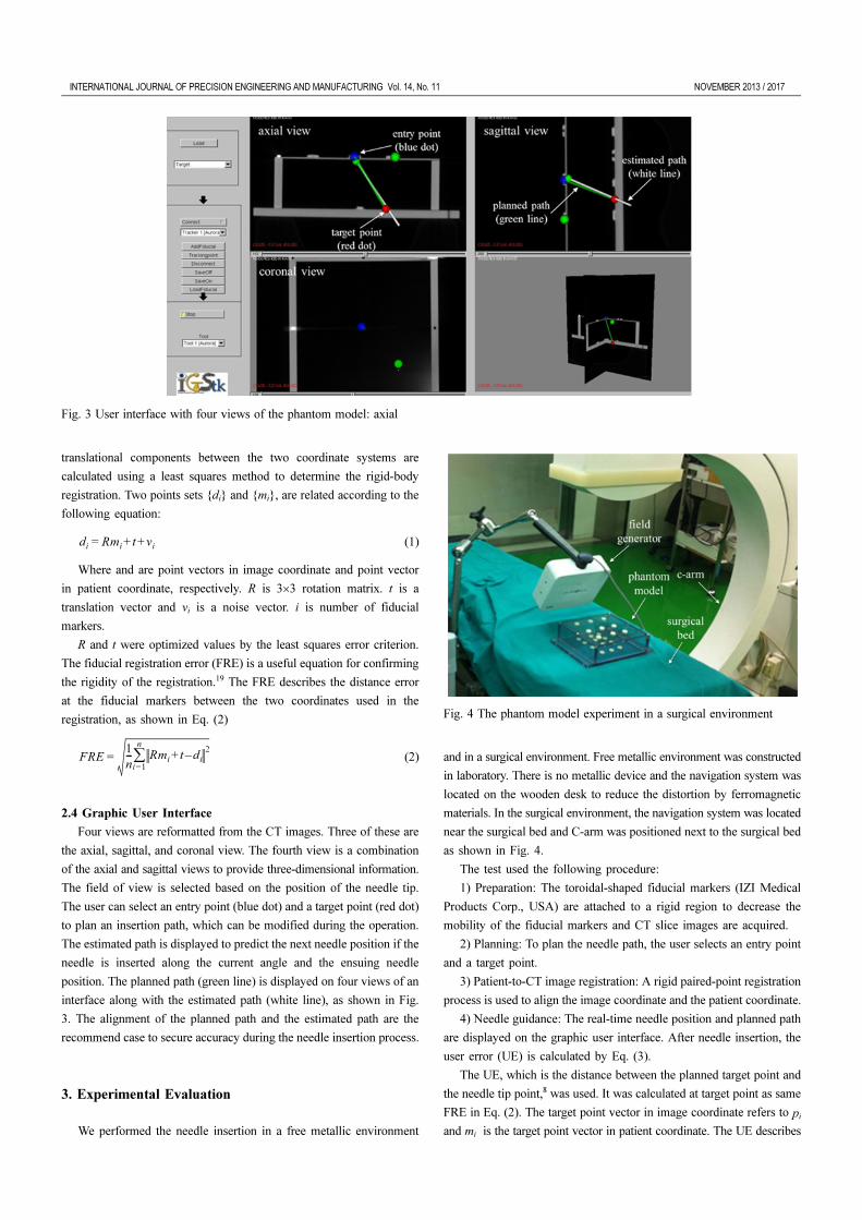
3. Experimental Evaluation
We performed the needle insertion in a free metallic environment
and in a surgical environment. Free metallic environment was constructed
in laboratory. There is no metallic device and the navigation system was
located on the wooden desk to reduce the distortion by ferromagnetic
materials. In the surgical environment, the navigation system was located
near the surgical bed and C-arm was positioned next to the surgical bed
as shown in Fig. 4.
The test used the following procedure:
1) Preparation: The toroidal-shaped fiducial markers (IZI Medical
Products Corp., USA) are attached to a rigid region to decrease the
mobility of the fiducial markers and CT slice images are acquired.
2) Planning: To plan the needle path, the user selects an entry point
and a target point.
3) Patient-to-CT image registration: A rigid paired-point registration
process is used to align the image coordinate and the patient coordinate.
4) Needle guidance: The real-time needle position and planned path
are displayed on the graphic user interface. After needle insertion, the
user error (UE) is calculated by Eq. (3).
The UE, which is the distance between the planned target point and
the needle tip point,8 was used. It was calculated at target point as same
FRE in Eq. (2). The target point vector in image coordinate refers to pi
and mi is the target point vector in patient coordinate. The UE describes
di
Rmi
t vi
+ +=
FRE1
n--- Rm
it d
i–+
2
i=1
n
∑=
Fig. 3 User interface with four views of the phantom model: axial
Fig. 4 The phantom model experiment in a surgical environment

2018 / NOVEMBER 2013 INTERNATIONAL JOURNAL OF PRECISION ENGINEERING AND MANUFACTURING Vol. 14, No. 11
how well the user can insert the needle using the developed navigation
system in the image coordinate.
(3)
First, the board was used to compare the difference of tracking
accuracy between the free metallic environment and the surgical
environment. The board is a rectangular acrylic board (200 mm×150
mm) with 63 measurement points as shown in Fig. 5. For registration,
four points (FM) at four corner points were used. After registration,
FRE was measured. 63 points of groove intersections were tapped with
the needle tip to measure the UE at each of the 63 points in the free
metallic environment and in the surgical environment. We could tap the
needle tip at the intersection point accurately, because we saw the
structure of the registration board and the needle tip.
Second, the phantom model was constructed as the similar structure
of the sacrum. The phantom model is a cubic-shaped model (200 mm×
200 mm×60 mm) and is filled with urethane foam. The toroidal-shaped
fiducial markers were attached on the bottom plate and the upper plate.
Four fiducial markers on the upper plate were used for the registration.
The other fiducial markers, which were attached on the bottom plate
60 mm away from the upper plate was used for the target points. The
fiducial markers on the bottom plate refer the sacral foramen. Subject
instructed to insert the needle into the center of the fiducial markers.
The UEs at the target point were measured from five subjects. Each
subject inserted the needle 10 trials in the free metallic environment. In
the surgical environment, one subject inserted 30 trials. During trial,
subject didn’t see the inside of the phantom model and only see the
outside and the fluoroscopic images from C-arm device.
4. Results
63 points were performed in the board with 4 trials. The results on
the board are represented in Fig. 6 and Table 1. The area and whiteness
of each marker refer the FRE. More white and larger circles indicate
higher UE. The mean FRE was 0.90±0.08 mm and the mean UE was
0.89±0.35 mm in the free metallic environment. In the surgical
environment, the mean FRE was 1.16±0.49 mm and the mean UE was
1.18±0.65 mm. The deviations of UE were different depending on the
positions of the points and whether or not the C-arm is used.
The results from the phantom model are represented in Table 2. The
mean FRE was 1.41±0.19 mm and the mean UE for five subjects was
5.08±1.27 mm in the free metallic environment. In the surgical
environment, the mean FRE was 0.76±0.11 mm and the mean UE was
4.26±2.87 mm from one subject (S6). The UE in the free metallic
UE1
n--- Rm
it p
i–+
2
i=1
n
∑=
Fig. 5 Top view of the board. Four points (FM) are used for registration
and 63 points of groove intersections in the board are touched by the
needle tip to assess the user error (UE)
Fig. 6 Deviations of the user error (UE) on the board’s surface (a) in the
free metallic environment and (b) in the surgical Top view of the board
Four points (FM) are used for registration and 63 points of groove
intersections in the board are touched by the needle tip to assess
Table 1 The UE and the FRE with the board in the free metallic
environment and in the surgical environment
Free metallic environment Surgical environment
Exp. UE (mm) FRE (mm) UE (mm) FRE (mm)
1 1.0±10.49 1.34 1.37±0.43 1.34
2 0.9±10.31 1.41 0.88±0.41 1.41
3 0.8±40.22 1.13 1.12±0.45 1.13
4 0.80±0.27 1.56 1.25±0.54 1.56
Mean 0.89±0.35 0.90±0.08 1.18±0.65 1.16±0.49

INTERNATIONAL JOURNAL OF PRECISION ENGINEERING AND MANUFACTURING Vol. 14, No. 11 NOVEMBER 2013 / 2019
environment did not differ from that in the surgical environment (Table
2).
5. Discussion and Conclusion
Sacral nerve stimulation (SNS) is a therapeutic medical procedure
to treat overactive bladder and fecal incontinence. In the conventional
SNS procedure, the physician uses 2D fluoroscopic images from a C-
arm device repeatedly to insert the needle near the sacral nerve. This
method solely depends on the physician’s experience and ability and
increases radiation exposure to the physician and the patient. To guide
the needle to the target point, we developed a navigation system during
SNS.
For the registration process, rigid paired-point registration was used
with skin fiducial markers. The centers of the fiducial markers were
tapped with the needle tip in the patient coordinate and localized on CT
images in the image coordinate. We measured the FRE in the free
metallic environment and in the surgical environment. The FRE is the
root mean square error, as expressed by Eq. (2). The measured FREs
were consistent in both environments (Table 1 and Table 2). The
registration error came from the misalignment of the centers of the
fiducial markers between the patient coordinate and the images
coordinate and the variation during the tapping at the centers of the
fiducial markers. And the electromagnetic tracking device contains the
inherent tracking error of the needle tip position. The mean position
error is 0.71±0.43 mm, and it can be changed due to the needle
orientation.21 The FRE can be also increased by the shifting and
movement of skin fiducial markers when used on humans or animals.
The developed navigation system was evaluated in the phantom
model. The UE, which is the distance between the planned target point
and the needle tip in the image coordinate, was measured in the free
metallic environment and in the surgical environment to validate the
feasibility of the system for needle guidance. The phantom model was
contracted as similar situation like the sacrum. The measured UE was
lower than the threshold values, which were the height and width of the
sacral foramen20; they were mainly related to human manipulation error
more than the errors of the navigation system and showed no significant
differences in the free metallic environment and the surgical environment.
From the experimental results, we compared the findings here with
related studies involving an electromagnetic tracking device for needle
guidance. Most studies reported the FRE for the misalignment between
the image coordinate and the patient coordinate. The experimental
environments have differences, such as the use of a phantom and a
swine model6 and a cadaver model21. Banovac et al.6 and Khan et al.21
measured the overall error, which is the distance between the needle tip
point and the target point in the control CT scan. Krücker et al.22
measured the system error, which is the distance in the image coordinate
between the needle tip position and the actual needle. There are
limitations in this study. We did not operate the whole SNS procedures
during experiments and only inserted the needle using the developed
navigation. After the needle insertion, it is necessary to identify the
electrode location from medical images or muscle reaction from an
electrical stimulation. Additionally, our developed navigation was tested
in the phantom model, not in vivo although it was tested in the surgical
environment.
The navigation system developed here allow for accurate needle
insertion in conditioned environments. Needle insertion was performed
in a free metallic environment and in a surgical environment. After the
insertion of the needle, the UE was measured for an evaluation of the
quality of the needle insertion. However, rectifying the overall error
remains a challenge, and in vivo accuracy assessments offer a topic for
future work. We believe that our navigation approach has the potential
to improve clinical treatments for SNS considerably. To support the
clinical application of this system, there are remaining issues to be
assessed regarding the developed navigation system before it can be
used in an in vivo environment.
ACKNOWLEDGEMENT
This research was supported by Basic Science Research Program
through the National Research Foundation of Korea (NRF) funded by
the Ministry of Science, ICT & Future Planning (2010-0022871).
REFERENCES
1. Chai, T. C. and Mamo, G. J., “Modified techniques of S3 foramen
localization and lead implantation in S3 neuromodulation,” Urology,
Vol. 58, No. 5, pp. 786-790, 2001.
2. Yoo, D. J., “Three-dimensional human body model reconstruction and
manufacturing from CT medical image data using a heterogeneous
implicit solid based approach,” Int. J. Precis. Eng. Manuf., Vol. 12,
No. 2, pp. 293-301, 2011.
3. Koenig, T. R., Mettler, F. A., and Wagner, L. K., “Skin injuries from
fluoroscopically guided procedures: Part 2, review of 73 cases and
recommendations for minimizing dose delivered to patient,” American
Journal of Roentgenology, Vol. 177, No. 1, pp. 13-20, 2001.
4. Tjandra, J. J., Lim, J. F., and Matzel, K., “Sacral nerve stimulation:
An emerging treatment for faecal incontinence,” ANZ Journal of
Surgery, Vol. 74, No. 12, pp. 1098-1106, 2004.
5. Cleary, K. and Peters, T. M., “Image-guided interventions: Technology
review and clinical applications,” Annual Review of Biomedical
Table 2 The UE and the FRE for each subject (mean standard deviation);
The UE was measured during 10 trials on each subject in the free
metallic environment
Subjects UE (mm) FRE (mm)
Free metallic environment
Exp. UE (mm) FRE (mm)
S1 5.23±1.22 1.34
S2 4.80±2.06 1.41
S3 4.12±1.25 1.13
S4 3.69±2.37 1.56
S5 4.55±1.54 1.60
Mean 5.08±1.27 1.41±0.19
Surgical environment
S6 4.26±2.87 0.76±0.11

2020 / NOVEMBER 2013 INTERNATIONAL JOURNAL OF PRECISION ENGINEERING AND MANUFACTURING Vol. 14, No. 11
Engineering, Vol. 12, No. pp. 119-142, 2010.
6. Banovac, F., Tang, J., Xu, S., Lindisch, D., Chung, H. Y., and Levy,
E. B. et. al, “Precision targeting of liver lesions using a novel
electromagnetic navigation device in physiologic phantom and
swine,” Medical Physics, Vol. 32, No. 8, pp. 2698-2705, 2005.
7. Banovac, F., Glossop, N., Lindisch, D., Tanaka, D., Levy, E., and
Cleary, K., “Liver tumor biopsy in a respiring phantom with the
assistance of a novel electromagnetic navigation device,” Proc. of
the 5th International Conference on Medical Image Computing and
Computer-Assisted Intervention-Part I, pp. 200-207, 2002.
8. Maier-Hein, L., Tekbas, A., Seitel, A., Pianka, F., Muller, S. A., and
Satzl, S., et. al, “In vivo accuracy assessment of a needle-based
navigation system for CT-guided radiofrequency ablation of the
liver,” Medical Physics, Vol. 35, No. 12, pp. 5385-5396, 2008.
9. Cleary, K., Ibanez, L., Ranjan, S., and Blake, B. “IGSTK: A software
toolkit for image-guided surgery applications,” Proc. of the 18th
International Congress and Exhibition - Computer Assisted Radiology
and Surgery, Vol. 1268, pp. 473-479, 2004.
10. Yaniv, Z., Cheng, P., Wilson, E., Popa, T., Lindisch, D., and Campos-
Nanez, E. et. al, “Needle-based interventions with the image-guided
surgery toolkit (IGSTK): From phantoms to clinical trials,” IEEE
Transactions on Biomedical Engineering, Vol. 57, No. 4, pp. 922-933,
2010.
11. Huynh, L. M. and Kim, Y. H., “A computer-aided and robot-assisted
surgical system for reconstruction of anterior cruciate ligament,” Int.
J. Precis. Eng. Manuf., Vol. 14, No. 1, pp. 49-54, 2013.
12. Nixon, M. A., McCallum, B. C., Fright, W. R., and Price, N. B., “The
effects of metals and interfering fields and on electromagnetic
trackers,” Presence: Teleoperators & Virtual Environments, Vol. 7,
No. 2, pp. 204-218, 1998.
13. Hummel, J., Figl, M., Kollmann, C., Bergmann, H., and Birkfellner,
W., “Evaluation of a miniature electromagnetic position tracker,”
Medical Physics, Vol. 29, No. 10, pp. 2205-2212, 2002.
14. Frantz, D. D., Wiles, A. D., Leis, S. E., and Kirsch, S. R., “Accuracy
assessment protocols for electromagnetic tracking systems,” Physics
in Medicine & Biology, Vol. 48, No. 14, pp. 2241-2251, 2003.
15. Hummel, J., Figl, M., Birkfellner, W., Bax, M. R., Shahidi, R., Maurer,
C. R., and Bergmann, H., “Evaluation of a new electromagnetic
tracking system using a standardized assessment protocol,” Physics
in Medicine & Biology, Vol. 51, No. 10, pp. 205-210, 2006.
16. Daneshgari F., “Applications of neuromodulation of the lower urinary
tract in female urology,” International Brazilian Journal of Urology,
Vol. 32, No. 3, pp. 262-272, 2006.
17. Schwald, B. and Seibert, H., “Registration tasks for a hybrid tracking
system for medical augmented reality,” Journal of WSCG, pp. 411-
418, 2004.
18. Arun, K. S., Huang, T. S., and Blostein, S. D., “Least-squares fitting
of two 3-D point sets,” IEEE Transactions on Pattern Analysis and
Machine Intelligence, Vol. PAMI-9, No. 5, pp. 698-700, 1987.
19. Fitzpatrick, J. M., West, J. B., and Maurer, C. R., “Predicting error in
rigid-body point-based registration,” IEEE Transactions on Medical
Imaging, Vol. 17, No. 5, pp. 694-702, 1998.
20. Arman, C., Naderi, S., Kiray, A., Aksu, F. T., Yilmaz, H. S., and
Tetik, S. et. al, “The human sacrum and safe approaches for screw
placement,” Journal of Clinical Neuroscience, Vol. 16, No. 8, pp.
1046-1049, 2009.
21. Khan, M. F., Dogan, S., Maataoui, A., Wesarg, S., Gurung, J., and
Ackermann, H. et. al, “Navigation-based needle puncture of a
cadaver using a hybrid tracking navigational system,” Investigative
Radiology, Vol. 41, No. 10, pp. 713-720, 2006.
22. Krucker, J., Xu, S., Glossop, N., Viswanathan, A., Borgert, J., Schulz,
H., and Wood, B. J., “Electromagnetic tracking for thermal ablation
and biopsy guidance: Clinical evaluation of spatial accuracy,” Journal
of Vascular and Interventional Radiology, Vol. 18, No. 9, pp. 1141-
1150, 2007.