
Electromagnetic Interference in Automotive and Aerospace
32
Innovation Intelligence ® Electromagnetic Interference in Automotive and Aerospace
Transcript of Electromagnetic Interference in Automotive and Aerospace

Innovation Intelligence®
Electromagnetic Interference in
Automotive and Aerospace

Innovation Intelligence®
1. Automotive

Copyright © 2014 Altair Engineering, Inc. Proprietary and Confidential. All rights reserved.
Problem description
• > 100 cable instances, > 50 connectors
• Only one of many harnesses
• Kilometers of cable in a car
• Unintended electrical interference and radiation
Courtesy Daimler AG

Copyright © 2014 Altair Engineering, Inc. Proprietary and Confidential. All rights reserved.
Case study
• Two harnesses and one windshield antenna
• Four signal conductors per harness
• Interference?

Copyright © 2014 Altair Engineering, Inc. Proprietary and Confidential. All rights reserved.
Differential cross talk
Between separate harnesses
Take a closer look at 34 MHz

Copyright © 2014 Altair Engineering, Inc. Proprietary and Confidential. All rights reserved.
Antenna causes large coupling
Important to test entire car, not just components.
Can only test entire car late in the process modifications expensive.
Software simulation essential.

Copyright © 2014 Altair Engineering, Inc. Proprietary and Confidential. All rights reserved.
EMC standard: max E on 10-m sphere
at every frequency

Copyright © 2014 Altair Engineering, Inc. Proprietary and Confidential. All rights reserved.
Account for spectrum digital signal
Clock
2 MHz
PRBS
2 Mb/s

Copyright © 2014 Altair Engineering, Inc. Proprietary and Confidential. All rights reserved.
With shielding
How much shielding is enough?
Don’t want to add much weight;
Don’t want to lose routing flexibility.

Copyright © 2014 Altair Engineering, Inc. Proprietary and Confidential. All rights reserved.
Interference on receiving antenna
Matching circuit designed with Optenni Lab. Low S11 89-91 MHz.

Copyright © 2014 Altair Engineering, Inc. Proprietary and Confidential. All rights reserved.
Received by antenna
CISPR 25 limit

Innovation Intelligence®
2. Lightning

Copyright © 2014 Altair Engineering, Inc. Proprietary and Confidential. All rights reserved.
Model similar to measurement setup

Copyright © 2014 Altair Engineering, Inc. Proprietary and Confidential. All rights reserved.
Lightning profile and spectrum
Defined in Standard IEC 62305
Preferred over double exponential
Current (kA)
Time (s)
Need to include frequencies
at least up to 300 kHz.
In these simulations:
10 Hz – 3 MHz.

Copyright © 2014 Altair Engineering, Inc. Proprietary and Confidential. All rights reserved.
Currents with and without shielding
Important to know how
much shielding is enough.
Don’t want to add
too much weight and
don’t want to lose flexibility.
Up to 1400 mA
Up to 22 mA

Copyright © 2014 Altair Engineering, Inc. Proprietary and Confidential. All rights reserved.
Change fuselage to CFRC material

Copyright © 2014 Altair Engineering, Inc. Proprietary and Confidential. All rights reserved.
Carbon-Fiber Reinforced Composite
material
• Directions of fibers:
0, 90, 45, 135 degrees
• Anisotropic Conductivity
1000 S/m along fibers
10 S/m perpendicular to fibers
• Thickness 0.5 mm per layer
plus 0.1 mm bonding
• FEKO translates the stack-up
into a frequency-dependent
anisotropic surface impedance.
Copyright © 2014 Altair Engineering, Inc. Proprietary and Confidential. All rights reserved.
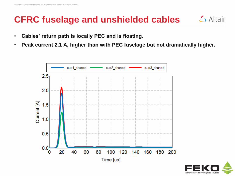
CFRC fuselage and unshielded cables
• Cables’ return path is locally PEC and is floating.
• Peak current 2.1 A, higher than with PEC fuselage but not dramatically higher.

Copyright © 2014 Altair Engineering, Inc. Proprietary and Confidential. All rights reserved.
CFRC fuselage without windows
• Cables’ return path is locally PEC and is floating.
• Currents at cable terminals larger than with windows.
• PEC fuselage: fields enter through windows
• CFRC fuselage: fields penetrate regardless of windows

Copyright © 2014 Altair Engineering, Inc. Proprietary and Confidential. All rights reserved.
Result with better cable shielding
• Denser braided shield than before

Copyright © 2014 Altair Engineering, Inc. Proprietary and Confidential. All rights reserved.
Observations
• Most lightning power enters through the windows if the fuselage is
metal, but through the material if it is CFRC.
• FEKO quantifies the currents at the ends of electrical cables, i.e. the
currents that enter the systems that are attached to the cables.
• Determining how much cable shielding is needed is straightforward.

Innovation Intelligence®
3. High-Intensity Radiated Fields
(HIRF)

Copyright © 2014 Altair Engineering, Inc. Proprietary and Confidential. All rights reserved.
HIRF on UAV
Length body 1.21 m
Length nose to tail 2.23 m
Wing span 4.52 m
Glass dome for camera

Copyright © 2014 Altair Engineering, Inc. Proprietary and Confidential. All rights reserved.
Cables
• Two cable bundles inside: one shielded, one unshielded
• Cable length 0.67 m; dielectric medium is air.

Copyright © 2014 Altair Engineering, Inc. Proprietary and Confidential. All rights reserved.
High-Intensity Radiated Field threat
• Modeled as incident plane wave at 300 V/m
• Many directions of incidence, one at a time

Copyright © 2014 Altair Engineering, Inc. Proprietary and Confidential. All rights reserved.
Results (unshielded cables)
• Displaying only two angles of incidence to avoid clutter. Typical results were chosen.
Plexiglass
Carbon-fiber
composite
Aluminum
Note: glass dome always transparent to HIRF
97 MHz cable almost λ/4Low Q due to distance wires and return path.
Effective cable length slightly longer due to end
effects.
Copyright © 2014 Altair Engineering, Inc. Proprietary and Confidential. All rights reserved.
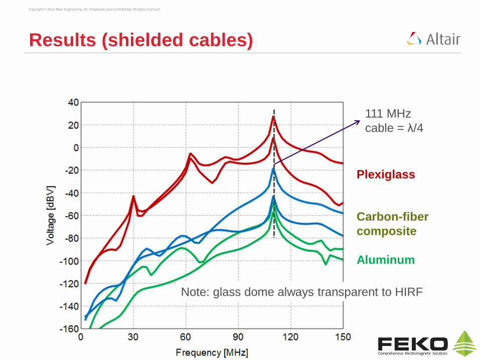
Results (shielded cables)
Plexiglass
Carbon-fiber
composite
Aluminum
Note: glass dome always transparent to HIRF
111 MHz
cable = λ/4

Copyright © 2014 Altair Engineering, Inc. Proprietary and Confidential. All rights reserved.
Composite material:
Comparison shielded and unshielded cables
unshielded
shielded
Displaying more angles of incidence and wider frequency range
97 MHz
3x97
5x97
1113x111
5x111

Copyright © 2014 Altair Engineering, Inc. Proprietary and Confidential. All rights reserved.
Observations
• With aluminum or carbon-fiber composite material, voltages remain modest,
in spite of transparent glass dome. Worst case 0.25 V.
• With plexiglass, interference reaches tens of Volts. This is not acceptable.
• Shielded cable (with one end open) shows remarkably strong resonance
when cable length equals ¼, ¾, … wavelength.

Copyright © 2014 Altair Engineering, Inc. Proprietary and Confidential. All rights reserved.
Copper-coated plexiglass
• Solid Lines:
Unshielded Bundle
• Dotted Lines:
Shielded Bundle
• Coating thickness
- Red 1 nm
- Blue 10 nm
- Green 100 nm
• Glass dome not coated

Copyright © 2014 Altair Engineering, Inc. Proprietary and Confidential. All rights reserved.
Observations
• Very thin coating already has large effect.
• At 100 MHz, skin depth is 6 μm
• However, 100 nm of copper can already carry enough current to provide a
shielding factor of several tens of dB!
Copyright © 2014 Altair Engineering, Inc. Proprietary and Confidential. All rights reserved.
Conclusions
• Automobiles: full-platform simulation essential.
• Metal aircraft: fields enter through windows.
• CFRC aircraft: fields enter through material and through windows.
• Lightning transient signal designing cable shielding is
straightforward.
• HIRF Continuous Wave (CW) signal resonances in cable harder
to suppress apply metal coating on the fuselage.
• 3D full-wave frequency-domain electromagnetic simulation tool
with a cable-analysis capability makes E3 mitigation easy.


