ElectroMagnetic Field Measurements Product … 2 of 16 ElectroMagnetic Field Measurements...
16
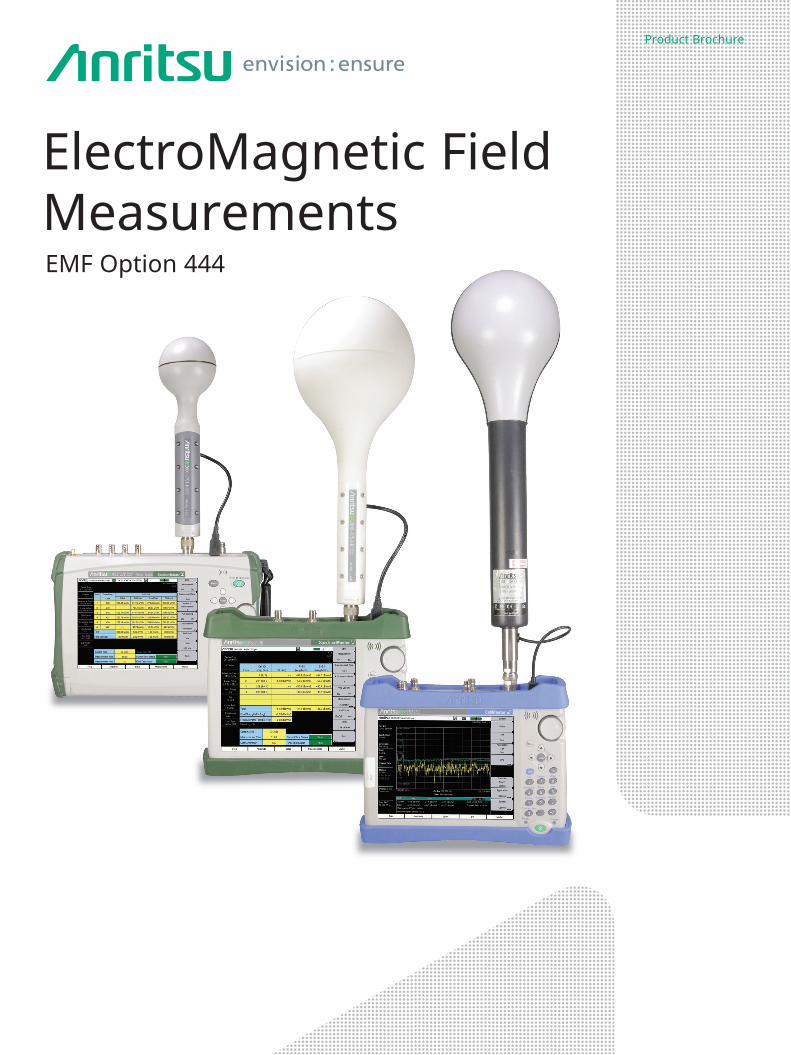
Product Brochure ElectroMagnetic Field Measurements EMF Option 444
Transcript of ElectroMagnetic Field Measurements Product … 2 of 16 ElectroMagnetic Field Measurements...
Product Brochure
ElectroMagnetic Field MeasurementsEMF Option 444
Page 2 of 16
ElectroMagnetic Field Measurements
Anritsu’s ElectroMagnetic Field (EMF) Measurements are designed to measure radiation compliance with various national standards for personal safety set by governmental regulatory authorities. Many countries have mandated EMF safety testing in areas where cellular or other high power transmission antennas are located. The EMF option is primarily targeted to both cellular operators and government regulators. Additionally, contractors and small service companies perform building inspections and field surveys to monitor radiation exposure intensities in areas situated near transmission antennas.
Anritsu’s EMF Measurements are designed to be easy to use, while providing the user with numerous automated features which will enable them to do their job quickly and more efficiently. ElectroMagnetic field measurements (EMF, Option 444) are available on the following Anritsu Spectrum Master™, Cell Master™ and LMR Master™ products: MS2711E, MS2712E, MS2713E, MS2720T, MT8212E, MT8213E and S412E. Firmware version 1.56 or later is required for the MS2711E/12E/13E and MT8212E/13E. For the MS2720T and S412E firmware version 1.12 or later is required.
EMF Option (444) provides the capability to measure electromagnetic field radiation when used in conjunction with an Anritsu isotropic antenna. Automated measurements can be taken using user-definable time intervals.
EMF Measurements Key Features and Benefits• Limit lines that are user-settable at various power levels across the spectrum• Limits can be saved for recall at a later time• Axis dwell time is user-settable (time that each axis [ X, Y, and Z ] measures radiation before
switching to next axis)• Pass/Fail indicators on screen for immediate feedback on test results• Automatic save feature for easy storage of measurement results to internal memory (auto-
logging) or USB stick• Results provided for maximum, minimum, average of all measurements conducted• Clear display of measurement status, measurement time, number of measurements taken, and
most other user settings• Measurement time is user-configurable• Pre-amp standard for measurements of low-level signals (optional for MS2711E)
Available field strength units include the following: (S412E Supports Spectrum Analyzer and LTE Modes ONLY)• Spectrum Analyzer Mode: dBm/m2, dBmV/m, dBuV/m, V/m, W/m2, dBW/m2, A/m, dBA/m, W/cm2
• LTE and TD-LTE Mode: dBm/m2, V/m, W/m2
• W-CDMA Mode: dBm/m2, V/m, W/m2, % of Limit (V/m), % of Limit (W/m2)For wideband radiation measurements, the EMF option operates in Spectrum Analyzer mode. Total radiation from all sources can be measured over the frequency band desired. The EMF option will also conduct radiation measurements of demodulated signals in specific frequency bands. In this way, measurements can be extrapolated assuming a fully-loaded traffic channel in order to present a worst-case analysis. Option 444 will work with demodulated signals of the following types: (S412E Supports LTE ONLY)
• W-CDMA• LTE• TD-LTE
If the user desires to measure EMF with a demodulated signal, the appropriate demodulation option also will need to be purchased. Additionally, Option 9 (demodulation) will need to be purchased if not offered as standard with the Spectrum Analyzer being used.
Customers with Spectrum Analyzers purchased previously may upgrade their units with the EMF Option 444. If EMF demodulation measurements are required, the appropriate demodulation option will also need to be purchased and installed.

Page 3 of 16
Isotropic AntennaIn order to conduct EMF measurements, an Anritsu isotropic antenna is required. Anritsu offers three isotropic antennas covering a frequency range from 9 kHz to 6 GHz. These antennas along with their corresponding frequency ranges are shown below.
• 9 kHz to 300 MHz H-Field Isotropic Antenna (Anritsu part number: 2000-1800-R )
• 30 MHz to 3 GHz E-Field Isotropic Antenna (Anritsu part number: 2000-1792-R)
• 700 MHz to 6 GHz E-Field Isotropic Antenna (Anritsu part number: 2000-1791-R)
ElectroMagnetic Field Measurements
E-Field Isotropic Antenna 30 MHz to 3 GHz 2000-1792-R
E-Field Isotropic Antenna 700 MHz to 6 GHz 2000-1791-R
H-Field Isotropic Antenna 9 kHz to 300 MHz 2000-1800-R
Each antenna contains a tri-axis sensor with an integrated RF switch device, microcontroller and memory. Each of the three sensors is situated orthogonally inside the antenna housing to transmit and receive a spherical radiation pattern. In this way, all radiation at the antenna’s geographical position is measured, regardless of direction of arrival.
The RF switch, microcontroller, and memory inside the antenna are controlled by firmware in the Spectrum Analyzer via a USB cable. The microcontroller operates the RF switch, controlling which probe is active. Once all three probes are switched, a composite RMS calculation is made. The memory inside the antenna is used to store parameters associated with that particular antenna. This includes serial number, date of compliance testing, antenna frequency range, and antenna factors.
Each isotropic antenna is characterized over its entire frequency range. The antenna factors are stored in the antenna’s memory and automatically downloaded into the Spectrum Analyzer once the antenna USB cable is inserted.
Page 4 of 16
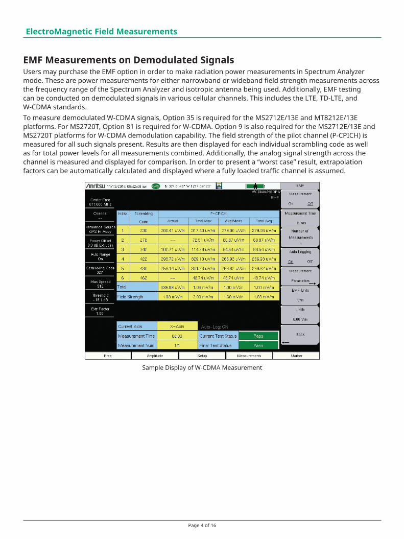
EMF Measurements on Demodulated SignalsUsers may purchase the EMF option in order to make radiation power measurements in Spectrum Analyzer mode. These are power measurements for either narrowband or wideband field strength measurements across the frequency range of the Spectrum Analyzer and isotropic antenna being used. Additionally, EMF testing can be conducted on demodulated signals in various cellular channels. This includes the LTE, TD-LTE, and W-CDMA standards. To measure demodulated W-CDMA signals, Option 35 is required for the MS2712E/13E and MT8212E/13E platforms. For MS2720T, Option 81 is required for W-CDMA. Option 9 is also required for the MS2712E/13E and MS2720T platforms for W-CDMA demodulation capability. The field strength of the pilot channel (P-CPICH) is measured for all such signals present. Results are then displayed for each individual scrambling code as well as for total power levels for all measurements combined. Additionally, the analog signal strength across the channel is measured and displayed for comparison. In order to present a “worst case” result, extrapolation factors can be automatically calculated and displayed where a fully loaded traffic channel is assumed.
ElectroMagnetic Field Measurements
Sample Display of W-CDMA Measurement
Page 5 of 16
ElectroMagnetic Field Measurements
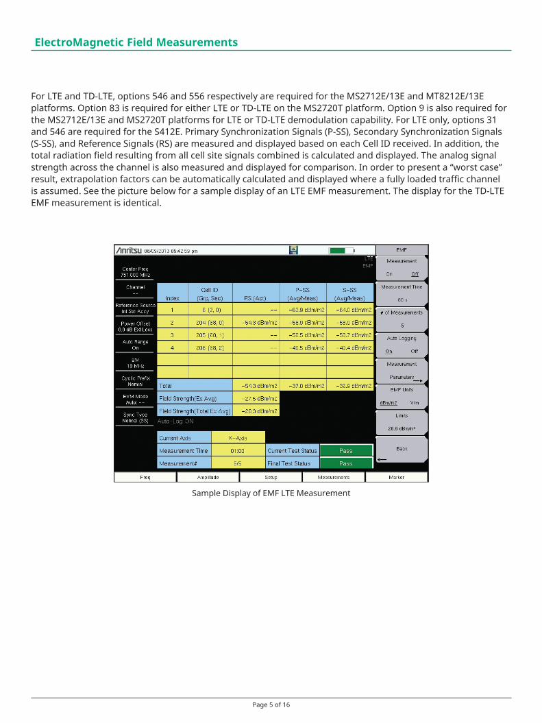
For LTE and TD-LTE, options 546 and 556 respectively are required for the MS2712E/13E and MT8212E/13E platforms. Option 83 is required for either LTE or TD-LTE on the MS2720T platform. Option 9 is also required for the MS2712E/13E and MS2720T platforms for LTE or TD-LTE demodulation capability. For LTE only, options 31 and 546 are required for the S412E. Primary Synchronization Signals (P-SS), Secondary Synchronization Signals (S-SS), and Reference Signals (RS) are measured and displayed based on each Cell ID received. In addition, the total radiation field resulting from all cell site signals combined is calculated and displayed. The analog signal strength across the channel is also measured and displayed for comparison. In order to present a “worst case” result, extrapolation factors can be automatically calculated and displayed where a fully loaded traffic channel is assumed. See the picture below for a sample display of an LTE EMF measurement. The display for the TD-LTE EMF measurement is identical.
Sample Display of EMF LTE Measurement

Page 6 of 16
Isotropic Antenna SpecificationsThe 2000-1800-R isotropic antenna is a tri-axis H-Field sensor with an integrated RF switch. The RF switch is controlled by the analyzer via a USB port.
Each antenna comes with a Certificate of Compliance and supporting test data.
Electrical Characteristics (2000-1800-R)
2000-1800-R H-Field sensor
Sensor Type Three Axis sensor with scanned axes
Frequency Range 9 kHz to 300 MHz
1 dB Compression Point at Output 118 dBµV typical
Decoupling of the axis > 20 dB typical
VSWR < 1.5 (20 kHz - 50 MHz) typical
RF Connector N-Connector Male, 50 Ω
Supply and Control USB
VSWR (typical) Antenna Factors (typical)
Magnetic Antenna Factor (typical)
ElectroMagnetic Field Measurements
Page 7 of 16
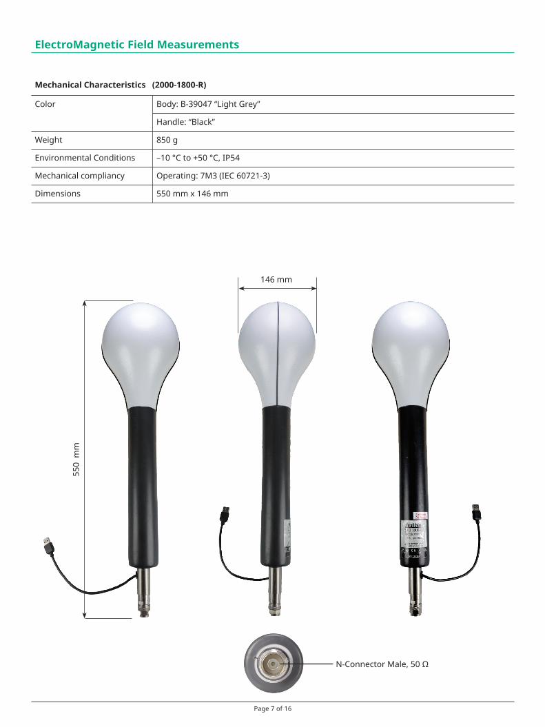
Mechanical Characteristics (2000-1800-R)
Color Body: B-39047 “Light Grey”
Handle: “Black”
Weight 850 g
Environmental Conditions –10 °C to +50 °C, IP54
Mechanical compliancy Operating: 7M3 (IEC 60721-3)
Dimensions 550 mm x 146 mm
ElectroMagnetic Field Measurements
146 mm
550
mm
N-Connector Male, 50 Ω
Page 8 of 16
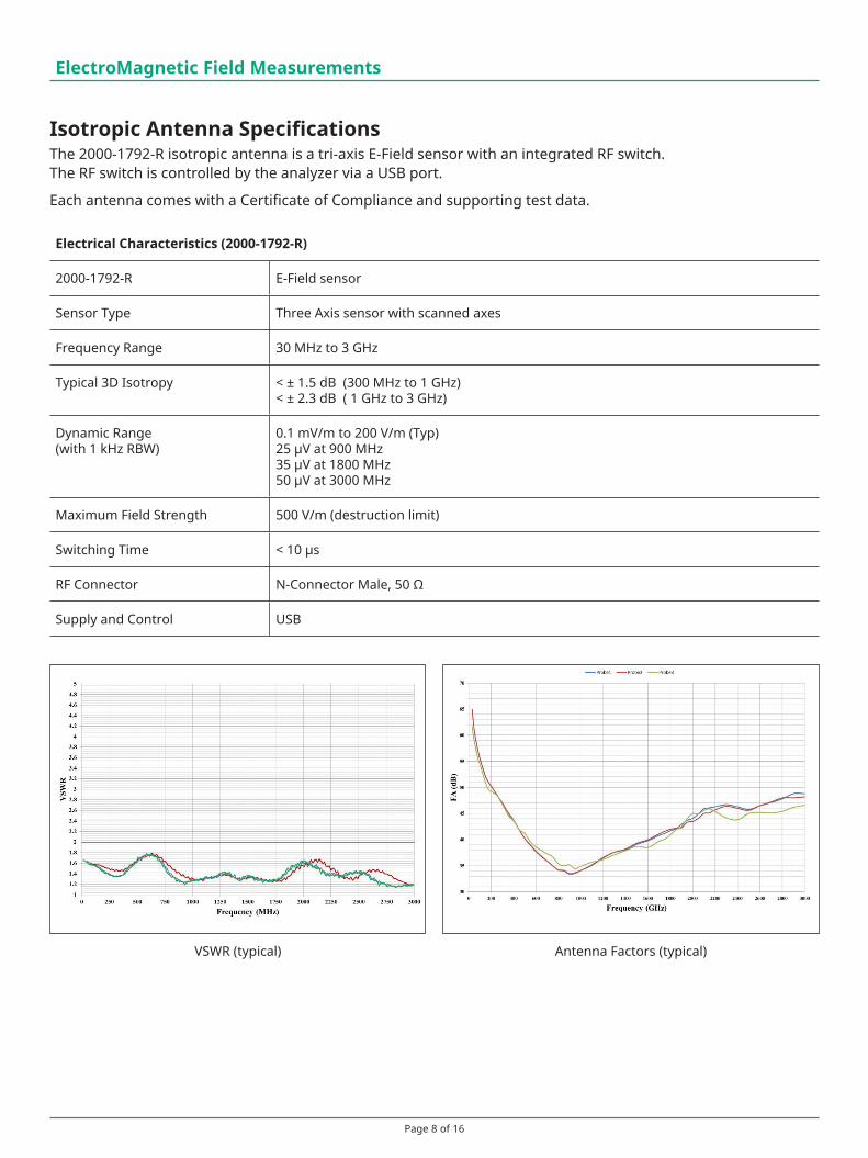
Isotropic Antenna SpecificationsThe 2000-1792-R isotropic antenna is a tri-axis E-Field sensor with an integrated RF switch. The RF switch is controlled by the analyzer via a USB port.
Each antenna comes with a Certificate of Compliance and supporting test data.
ElectroMagnetic Field Measurements
Electrical Characteristics (2000-1792-R)
2000-1792-R E-Field sensor
Sensor Type Three Axis sensor with scanned axes
Frequency Range 30 MHz to 3 GHz
Typical 3D Isotropy < ± 1.5 dB (300 MHz to 1 GHz) < ± 2.3 dB ( 1 GHz to 3 GHz)
Dynamic Range (with 1 kHz RBW)
0.1 mV/m to 200 V/m (Typ) 25 µV at 900 MHz 35 µV at 1800 MHz 50 µV at 3000 MHz
Maximum Field Strength 500 V/m (destruction limit)
Switching Time < 10 μs
RF Connector N-Connector Male, 50 Ω
Supply and Control USB
VSWR (typical) Antenna Factors (typical)
Page 9 of 16
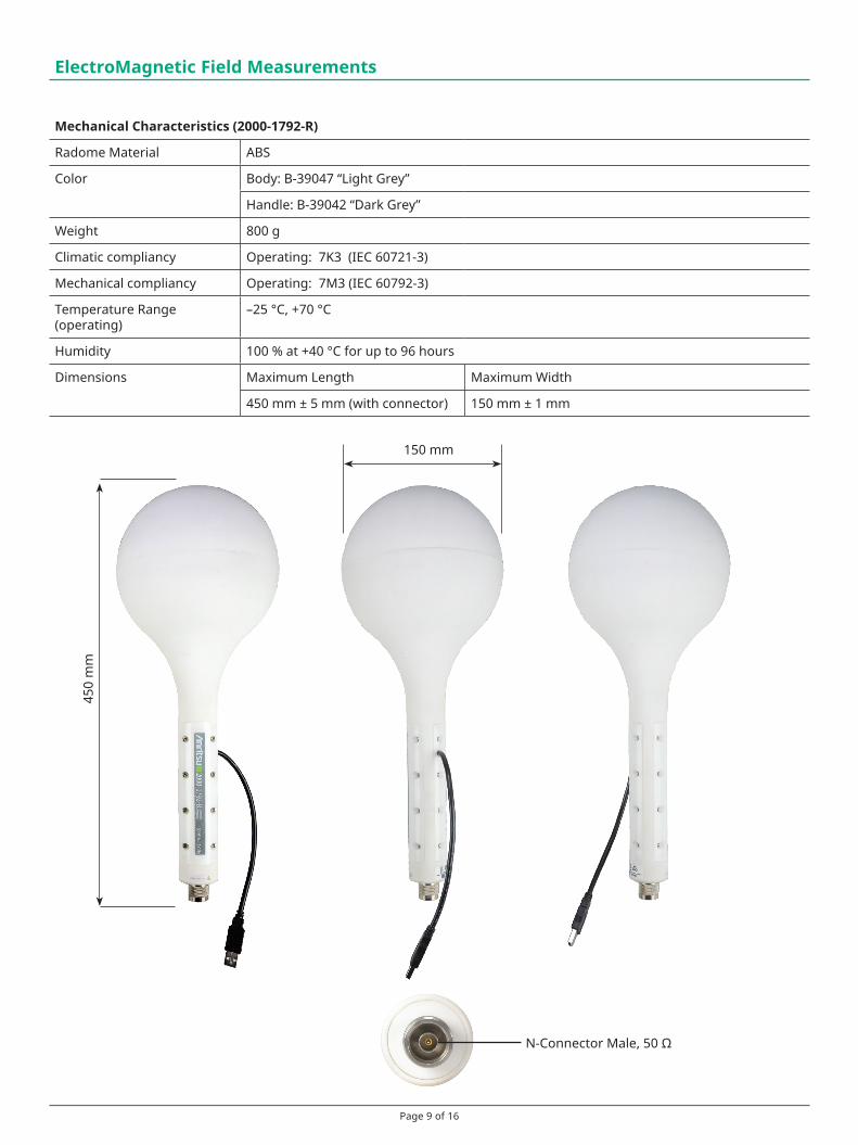
Mechanical Characteristics (2000-1792-R)
Radome Material ABS
Color Body: B-39047 “Light Grey”
Handle: B-39042 “Dark Grey”
Weight 800 g
Climatic compliancy Operating: 7K3 (IEC 60721-3)
Mechanical compliancy Operating: 7M3 (IEC 60792-3)
Temperature Range (operating)
–25 °C, +70 °C
Humidity 100 % at +40 °C for up to 96 hours
Dimensions Maximum Length Maximum Width
450 mm ± 5 mm (with connector) 150 mm ± 1 mm
ElectroMagnetic Field Measurements
150 mm
450
mm
N-Connector Male, 50 Ω

Page 10 of 16
Isotropic Antenna SpecificationsThe 2000-1791-R isotropic antenna is a tri-axis E-Field sensor with an integrated RF switch. The RF switch is controlled by the analyzer via a USB port.
Each antenna comes with a Certificate of Compliance and supporting test data.
ElectroMagnetic Field Measurements
Electrical Characteristics (2000-1791-R)
2000-1791-R E-Field sensor
Sensor Type Three Axis sensor with scanned axes
Frequency Range 700 MHz to 6 GHz
Typical 3D Isotropy ≤ ± 2 dB (0.7 GHz to 2 GHz) ≤ ± 2.5 dB (2 GHz to 3.6 GHz) ≤ ± 3.5 dB (3.6 GHz to 6 GHz)
Dynamic Range(with 1 kHz RBW)
0.2 mV/m to 200 V/m (typical)
Maximum Field Strength 500 V/m (destruction limit)
Switching Time < 10 μs
RF Connector N-Connector Male, 50 Ω
Supply and Control USB
VSWR (typical) Antenna Factors (typical)
Page 11 of 16
87 mm
320
mm
ElectroMagnetic Field Measurements
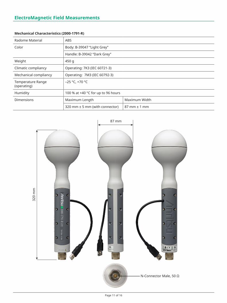
Mechanical Characteristics (2000-1791-R)
Radome Material ABS
Color Body: B-39047 “Light Grey”
Handle: B-39042 “Dark Grey”
Weight 450 g
Climatic compliancy Operating: 7K3 (IEC 60721-3)
Mechanical compliancy Operating: 7M3 (IEC 60792-3)
Temperature Range (operating)
–25 °C, +70 °C
Humidity 100 % at +40 °C for up to 96 hours
Dimensions Maximum Length Maximum Width
320 mm ± 5 mm (with connector) 87 mm ± 1 mm
N-Connector Male, 50 Ω

Page 12 of 16
Required Instrument Options and AccessoriesPart Number Description
MS2711E-0444 EMF Option 444 for MS2711EMS2712E-0444 EMF Option 444 for MS2712EMS2713E-0444 EMF Option 444 for MS2713EMS2720T-0444 EMF Option 444 for MS2720TMT8212E-0444 EMF Option 444 for MT8212EMT8213E-0444 EMF Option 444 for MT8213E
S412E-0444 EMF Option 444 for S412E2000-1800-R Isotropic Antenna, 9 kHz to 300 MHz, N Connector (male), 50 Ω2000-1792-R Isotropic Antenna, 30 MHz to 3 GHz, N Connector (male), 50 Ω2000-1791-R Isotropic Antenna, 700 MHz to 6 GHz N Connector (male), 50 Ω
200-1528-R GPS Antenna, SMA(m) with 15 ft cable
Related Instrument OptionsPart Number Description
MS2712E-0009 20 MHz Bandwidth Demodulation for MS2712EMS2713E-0009 20 MHz Bandwidth Demodulation for MS2713EMS2720T-0009 20 MHz Bandwidth Demodulation for MS2720T
MS2712E-0035 W-CDMA OTA Measurements for MS2712E*MS2713E-0035 W-CDMA OTA Measurements for MS2713E*MS2720T-0881 W-CDMA OTA Measurements for MS2720T*MT8212E-0035 W-CDMA OTA Measurements for MT8212EMT8213E-0035 W-CDMA OTA Measurements for MT8213E
MS2712E-0546 LTE OTA Measurements for MS2712E*MS2713E-0546 LTE OTA Measurements for MS2713E*MS2720T-0883 LTE OTA Measurements for MS2720T*MT8212E-0546 LTE OTA Measurements for MT8212EMT8213E-0546 LTE OTA Measurements for MT8213E
MS2712E-0556 TD-LTE OTA Measurements for MS2712E*MS2713E-0556 TD-LTE OTA Measurements for MS2713E*MS2720T-0883 TD-LTE OTA Measurements for MS2720T*MT8212E-0556 TD-LTE OTA Measurements for MT8212EMT8213E-0556 TD-LTE OTA Measurements for MT8213E
S412E-0006 6 GHz Coverage for S412E Spectrum AnalyzerS412E-0031 GPS Receiver for S412E (Requires suitable GPS Antenna)S412E-0546 LTE OTA Measurement for S412E (Requires Option 31)
*requires Option 9, 20 MHz Bandwidth Demodulation
Spectrum Master MS2712E with 2000-1792-R Isotropic Antenna
Cell Master MT8213E with 2000-1800-R Isotropic Antenna
Spectrum Master MS2720T with 2000-1791-R Isotropic Antenna
ElectroMagnetic Field Measurements

Page 13 of 16
Notes

Page 14 of 16
Notes

Page 15 of 16
Notes
® Anritsu All trademarks are registered trademarks of their respective owners. Data subject to change without notice. For the most recent specifications visit: www.anritsu.com
11410-00838, Rev. E Printed in United States 2017-03©2017 Anritsu Company. All Rights Reserved.
Anritsu utilizes recycled paper and environmentally conscious inks and toner.
• United States Anritsu Company1155 East Collins Boulevard, Suite 100, Richardson, TX, 75081 U.S.A. Toll Free: 1-800-267-4878 Phone: +1-972-644-1777 Fax: +1-972-671-1877
• Canada Anritsu Electronics Ltd.700 Silver Seven Road, Suite 120, Kanata, Ontario K2V 1C3, Canada Phone: +1-613-591-2003 Fax: +1-613-591-1006
• Brazil Anritsu Electrônica Ltda.Praça Amadeu Amaral, 27 - 1 Andar 01327-010 - Bela Vista - São Paulo - SP - Brazil Phone: +55-11-3283-2511 Fax: +55-11-3288-6940
• Mexico Anritsu Company, S.A. de C.V.Av. Ejército Nacional No. 579 Piso 9, Col. Granada 11520 México, D.F., México Phone: +52-55-1101-2370 Fax: +52-55-5254-3147
• United Kingdom Anritsu EMEA Ltd.200 Capability Green, Luton, Bedfordshire LU1 3LU, U.K. Phone: +44-1582-433280 Fax: +44-1582-731303
• France Anritsu S.A.12 avenue du Québec, Batiment Iris 1-Silic 612, 91140 Villebon-sur-Yvette, France Phone: +33-1-60-92-15-50 Fax: +33-1-64-46-10-65
• Germany Anritsu GmbHNemetschek Haus, Konrad-Zuse-Platz 1 81829 München, Germany Phone: +49-89-442308-0 Fax: +49-89-442308-55
• Italy Anritsu S.r.l.Via Elio Vittorini 129, 00144 Roma Italy Phone: +39-06-509-9711 Fax: +39-06-502-2425
• Sweden Anritsu ABKistagången 20B, 164 40 KISTA, Sweden Phone: +46-8-534-707-00 Fax: +46-8-534-707-30
• Finland Anritsu ABTeknobulevardi 3-5, FI-01530 VANTAA, Finland Phone: +358-20-741-8100 Fax: +358-20-741-8111
• Denmark Anritsu A/SKay Fiskers Plads 9, 2300 Copenhagen S, Denmark Phone: +45-7211-2200 Fax: +45-7211-2210
• Russia Anritsu EMEA Ltd. Representation Office in RussiaTverskaya str. 16/2, bld. 1, 7th floor. Moscow, 125009, Russia Phone: +7-495-363-1694 Fax: +7-495-935-8962
• Spain Anritsu EMEA Ltd. Representation Office in SpainEdificio Cuzco IV, Po. de la Castellana, 141, Pta. 8 28046, Madrid, Spain Phone: +34-915-726-761 Fax: +34-915-726-621
• United Arab Emirates Anritsu EMEA Ltd. Dubai Liaison OfficeP O Box 500413 - Dubai Internet City Al Thuraya Building, Tower 1, Suite 701, 7th floor Dubai, United Arab Emirates Phone: +971-4-3670352 Fax: +971-4-3688460
• India Anritsu India Pvt Ltd.2nd & 3rd Floor, #837/1, Binnamangla 1st Stage, Indiranagar, 100ft Road, Bangalore - 560038, India Phone: +91-80-4058-1300 Fax: +91-80-4058-1301
• Singapore Anritsu Pte. Ltd.11 Chang Charn Road, #04-01, Shriro House Singapore 159640 Phone: +65-6282-2400 Fax: +65-6282-2533
• P. R. China (Shanghai) Anritsu (China) Co., Ltd.27th Floor, Tower A, New Caohejing International Business Center No. 391 Gui Ping Road Shanghai, Xu Hui Di District, Shanghai 200233, P.R. China Phone: +86-21-6237-0898 Fax: +86-21-6237-0899
• P. R. China (Hong Kong) Anritsu Company Ltd.Unit 1006-7, 10/F., Greenfield Tower, Concordia Plaza, No. 1 Science Museum Road, Tsim Sha Tsui East, Kowloon, Hong Kong, P. R. China Phone: +852-2301-4980 Fax: +852-2301-3545
• Japan Anritsu Corporation8-5, Tamura-cho, Atsugi-shi, Kanagawa, 243-0016 Japan Phone: +81-46-296-6509 Fax: +81-46-225-8359
• Korea Anritsu Corporation, Ltd.5FL, 235 Pangyoyeok-ro, Bundang-gu, Seongnam-si, Gyeonggi-do, 463-400 Korea Phone: +82-31-696-7750 Fax: +82-31-696-7751
• Australia Anritsu Pty Ltd.Unit 21/270 Ferntree Gully Road, Notting Hill, Victoria 3168, Australia Phone: +61-3-9558-8177 Fax: +61-3-9558-8255
• Taiwan Anritsu Company Inc.7F, No. 316, Sec. 1, Neihu Rd., Taipei 114, Taiwan Phone: +886-2-8751-1816 Fax: +886-2-8751-1817
The Master Users Group is an organization dedicated to providing training, technical support, networking opportunities and links to Master product development teams. As a member you will receive the Insite Quarterly Newsletter with user stories, measurement tips, new product news and more.Visit us to register today: www.anritsu.com/MUG
Training at AnritsuAnritsu has designed courses to help you stay up to date with technologies important to your job.For available training courses visit: www.anritsu.com/training
Please Contact:


![Electromagnetic Field Theory [eBook]](https://static.fdocuments.us/doc/165x107/54782f0fb4af9f63108b4b45/electromagnetic-field-theory-ebook.jpg)