Electrocolour and other Colours, Titration, Curves and ...infohouse.p2ric.org/ref/28/27289.pdf ·...
17
ELECTROCOLOUR AND OTHER COLOURS, TITRATION, CURVES AND ELECTROLYTIC COLOURING BATH FOR ANODIZED ALUMINIUM Xavier Albert Ventura, Ph.D. in Chemistry LC Systeme Iberica, SA Puigcerdi, 127 H 080 19 Barcelona, Spain Abstract The properties produced by integral coloured anodic oxide films and sulphuric acid, oxalic acid, maleic acid and different anodizing aluminium alloys -Si, Mg, Fe, Cu- are studied. A two stage anodizing procedure was employed. The influence of alloy and solution composition, temperature, concentration, voltage, ampere, time from optimization simplex and anodizing conditions are considered. An oxide disordered structure is formed in the initial stage while an oriented structure is obtained in the second stage. The changes in colour parameters obtained with complex forming electrolytes are explained. Anodizing solutions: sulphosilicylic acid, sulphuric acid. phosphoric acid. Introduction The properties produced by integral coloured anodic oxide films and sulphuric acid, oxalic acid, maleic acid and different anodizing aluminium alloys -Si, Mg, Fe, Cu- are studied. A two stage anodizing procedure was employed. The influence of alloy and solution composition, temperature, concentration, voltage , ampere, time from optimization simplex and anodizing conditions are considered. An oxide disordered structure is formed in the initial stage while an oriented structure is obtained in the second stage. The changes in colour parameters obtained with complex forming electrolytes are explained. Anodizing solutions: sulforsalicylic acid, sulphuric acid, sulfamic acid. \ Anodic Oxidization Unlike the electrocoating processes in which the layer towards the electrode outer part, in anodic oxidization the layer growth is towards the inner part of the metal and therefore consuming it. lfwe concentrate on the faradic conversion of A1 to oxide, we observe that for each gram of metal consumed, 1.889 grs. of oxide is obtained. The coating relation is defined as the oxide amount formed per gram of reacted aluminium, which experimental value double weighting measurement show us the efficiency of the anodic process. The classification of the anodized layer during the formation process, can be made in accordance with the dissolvent amount of the electrolyte in that layer. Non-Porous Layer The non porous layers art: those which do not retain dissolvent in the formed oxide layer and therefore, are compact, dielectric and thinner. The layer thickness initially depends on the applied potential and temperature. In a dielectric environment if the potential applied is high enough. a strong discharge is produced, thus perforating the layer. We call this effect layers breakage. The electrolytes causing this type of breakage are aqueous dissolutions of borates, tartres. succionates, citrates, phosphates and carbonates. The breakage potential for the non porous layers, oscillates between 500 and 700 V and refers to thickness between 7,000 to 10,OOO i. If the applied potentials are lower, the current density becomes almost zero and the layer growth is gradually slowed down until becoming nonexistent. The velocity formation in the initial layer increases lineally in relation to the current density and the coating relation value near to the theoretical value of 1.889 as for a process that has not secondary reactions. Porous Layers Porous layers are those which do not hold dissolvent in the formed oxide layer. They are gelatinous and therefore thick and soft. In the 41 9
Transcript of Electrocolour and other Colours, Titration, Curves and ...infohouse.p2ric.org/ref/28/27289.pdf ·...

ELECTROCOLOUR AND OTHER COLOURS, TITRATION, CURVES AND ELECTROLYTIC COLOURING BATH FOR ANODIZED ALUMINIUM
Xavier Albert Ventura, Ph.D. in Chemistry LC Systeme Iberica, SA
Puigcerdi, 127 H 080 19 Barcelona, Spain
Abstract
The properties produced by integral coloured anodic oxide films and sulphuric acid, oxalic acid, maleic acid and different anodizing aluminium alloys -Si, Mg, Fe, Cu- are studied. A two stage anodizing procedure was employed. The influence of alloy and solution composition, temperature, concentration, voltage, ampere, time from optimization simplex and anodizing conditions are considered.
An oxide disordered structure is formed in the initial stage while an oriented structure is obtained in the second stage.
The changes in colour parameters obtained with complex forming electrolytes are explained.
Anodizing solutions: sulphosilicylic acid, sulphuric acid. phosphoric acid.
Introduction
The properties produced by integral coloured anodic oxide films and sulphuric acid, oxalic acid, maleic acid and different anodizing aluminium alloys -Si, Mg, Fe, Cu- are studied. A two stage anodizing procedure was employed. The influence of alloy and solution composition, temperature, concentration, voltage , ampere, time from optimization simplex and anodizing conditions are considered.
An oxide disordered structure is formed in the initial stage while an oriented structure is obtained in the second stage. The changes in colour parameters obtained with complex forming electrolytes are explained. Anodizing solutions: sulforsalicylic acid, sulphuric acid, sulfamic acid. \
Anodic Oxidization
Unlike the electrocoating processes in which the layer towards the electrode outer part, in anodic oxidization the layer growth is towards the inner
part of the metal and therefore consuming it. lfwe concentrate on the faradic conversion of A1 to oxide, we observe that for each gram of metal consumed, 1.889 grs. of oxide is obtained. The coating relation is defined as the oxide amount formed per gram of reacted aluminium, which experimental value double weighting measurement show us the efficiency of the anodic process.
The classification of the anodized layer during the formation process, can be made in accordance with the dissolvent amount of the electrolyte in that layer.
Non-Porous Layer
The non porous layers art: those which do not retain dissolvent in the formed oxide layer and therefore, are compact, dielectric and thinner. The layer thickness initially depends on the applied potential and temperature. In a dielectric environment if the potential applied is high enough. a strong discharge is produced, thus perforating the layer. We call this effect layers breakage.
The electrolytes causing this type of breakage are aqueous dissolutions of borates, tartres. succionates, citrates, phosphates and carbonates. The breakage potential for the non porous layers, oscillates between 500 and 700 V and refers to thickness between 7,000 to 10,OOO i. If the applied potentials are lower, the current density becomes almost zero and the layer growth i s gradually slowed down until becoming nonexistent.
The velocity formation in the initial layer increases lineally in relation to the current density and the coating relation value near to the theoretical value of 1.889 as for a process that has not secondary reactions.
Porous Layers
Porous layers are those which do not hold dissolvent in the formed oxide layer. They are gelatinous and therefore thick and soft. In the
41 9

porous layer the coating relation has a value of 1.35 to 1.56 due to the existing competitive effect of dissolution against that of oxide formation. The porous layer because of its physical characteristics cannot serve the purpose of being a protective layer. This is achieved through sealing. This seems to transform the superficial layer in small crystalline nuclei of hidratated oxide which several authors believe to be boehmite.
Characteristic Regarding Definition of Porous and Barrier Layers
Anodic aluminium oxide structures fall into two general categories: The porous layer structures and the non porous, or barrier-layer structure. Porous layers are so named because of the microscopic pore channels that run perpendicular (or at a slight angle) with respect to the metal substrate. These pore channels may be well ordered throughout the layer, or they may be fever and more randomly distributed, depending on the anodizing conditions and electrolyte.
A particular type of anodizing response is generally used to classify an anodic oxidized porous layer oxide. The voltage vs. time curve, for anodizing at constant current density, will generally be flat or will rise only slowly. Once anodizing is established, little or no voltage increment is required to maintain a constant current density, all other anodizing conditions being unchanged, and the film continues to grow to inappreciable thickness. Electrolytes that tend to dissolve aluminium oxide, either through complex formation or direct solubility, can be made to yield anodic porous layers. A common example is sulphuric acid. Porous oxide are also formed with phosphoric, chromic and many dicarboxylic acids, including plyfunctional mixed acid electrolytes such as 5- sulfosalicylic plus sulphuric acid, or other acids containing functional groups that contribute to complexing -chelating- ability. Some of these, however, require a continued voltage increase in order to maintain a constant current density, but these voltage increments are still less than that characterized by barrier type anodizing response, to be discussed next.
The non-porous or barrier layer, oxides are generally characterized by a glass-like insulating structure. This high dielectric oxide comprises most of the voltage barrier-voltage drops during anodizing. While this oxide is always found along
with porous-layer films, lying next to the metal substrate, below the porous layer, it can also be prepared by itself. The anodizing, response that characterizes only the formation of this type of oxide layer is entirely different from that of a porous-layer film, which contains both barrier and porous layers. The anodizing voltage vs. time relationship is usually linear but with a sharp - upward slope, at constant current density. Unlike that of the porous layer, the applied voltage must be continually increased in order to maintain a constant current density. Also unlike the porous layer situation, the anodizing current density will rapidly fall down toward zero if applied voltage is held at a constant value. For a pure barrier layer electrolyte, where no porous layer is formed, the final voltage reached during anodizing is thus an indirect measure of the quantity of coulomb spent in film formation: a constant currenthne relationship as the voltage is increased, with negligible current passing after the applied voltage reaches some preset maximum value. A voltage to film thickness relationship is often applied to this situation: between 10 and 20 &volt, depending on the electrolyte and anodizing conditions employed. Pure barrier layer oxide may be prepared in electrolytes with little or no complexing or solubility toward alumina, although, to this end, the anodizing conditions need to be rather specific. Boric acid or near-neutrality ammonium tartrate provide this type of aqueous electrolyte.
There are, however, some apparent anomalies in the formation of barrier and porous layer oxides. If aluminium is first anodized in sulphuric acid, a barrier layer will form first, followed by, and above this, the growth of a thicker, clear and colourless, porous layer. If this anodized metal is next anodized in an integral colour electrolyte, the coloured porous layer -a characteristic of this electrolyte- will be situated between the barrier layer and the first formed clear sulphuric acid film. Reversing this situation and anodizing first in the integral colour electrolyte, will put the colourecl porous layer above the clear -sulphuric anodized- porous layer. It therefore appears that the first layer to form will appear above subsequent layers, when the coating is prepared step-wise in successive anodizing
But why, then, is the barrier layer always situated beneath the porous layer or layers? Anodizing first in boric acid -a "pure" barrier layer electrolyte- and then in sulphuric acid produces the
~
-
~ ~
electrolytes. -

t
Same results as anodizing first in sulphuric and last in boric acid. The barrier layer is situated next to the metal substrate and underneath any porous layers that might have been formed. While many diverse explanations have heen set forth to explain this, the more plausible involve a series of oxide transformation mechanisms.
Electrochemical Process
Anodizing is that on the anodic half-cycle, at each electrode, when film formation takes place and that on the cathodic half-cycle film reduction does not take place and the continuous film growth can occur.
On the anodize half-cycle the main reaction is clearly oxide film formation expressed simply as
2 A1 + 6 OH--, AI 0 + 3H;O + 3e-
As thc voltage is increased some film dissolution oxcurs, leading to conventional porosity
AI + AI r3 + 3e
4 3 A1,03 + 3 H zO + 2 AI + 6 0 H -
and soma direct oxygen evolution may occur:
4 0 H - + 2 H 2 0 + 4a-
A side reaction also take place at higher voltage but probable not to any significant extent, oxidation of sulphate
-1 2 s o z ; * s x O$ + 2e-
On the cathode half-cycle hydrogen evolution is the main reaction
2 H + + 2e--, H,
With the reduction of sulphate as a minor side react ion
+ 0 -2 SO,, + 8H + 6e-- rS + 4 H 0 2
or
-2 SO .+ + 10 H + 8e-+ H 2 X + 4HL0 Its occurrence is clear from both the smell of H
S and the presence of sulphur in anodic film present ad S or S and quite distinct from SO,-' which is usually trapped residual acid electrolyte (4-8).
Two other reactions, theoretically possible at higher voltage, do not in practice occur and can be disregarded. They are alumina reaction
AI 0 + 6 H c + 6e-4 2 Al f 3 HzO 2 3
and aluminium electrodeposition
AI+^ + 3e+ AI
Any process improvement based on the electrochemistry will normally relate to elimination of the sulphate reduction reaction and two possibilities exist.
Firstly, the overvoltage for sulphate reduction could be raised or the overvoltage for hydrogen evolution lowered, thereby making sulphate reduction less favourable. Secondly, allowing sulphate redaction to take place but directing the sulphur or sulphide, thus formed away from the film preferably as some soluble species.
The Colouring of Anodized Aluminum
The process of anodizing aluminum goes back several decades,however several new advances and changing environmental needs have changed the colouring methods over the years. The purpose of this paper is to review the history and practices today as well as discuss what the future might bring.
Anodized aluminum can be coloured using the following methods.
.Chemical dyeing
.Adsorptive dyeing
.Electrolytic colouring
.Combination dyeing
.Interference colouring
.Other colouring methods
Integral Colouring
Integral colour anodizing took advantage of the metallurgical history of the aluminum alloy being coloured.It also made use of organic acids in
42 1

conjunction with sulphuric acid. The process became unpopular during the energy crisis due to the fact that high current densities were employed to achieve the desired "earth tones".
From a finishing standpoint, the process was touchy and required constant monitoring.It was also very alloy dependent,which helped lead to it's demise as a popular finishing process. Electrolytic colouring (which replaced integral colouring) gave all the advantages without all of the headaches.
Chmiical Dyeitig
In this method of colouring the. colouring matter is distributed in the hard aluminum oxide and is inseparably bound to the aluminum. The most common colour using this method is various shades of gold that look like brass. The brass shades are produced using either femc sodium oxalate or ferric ammonium oxalate. The ferric sodium oxalate chemical seems to be more stable in the tank and is also more desirable from the environmental aspect. Other colours like bronzes and greys can also be produced using this method buy are not very popular.
Electrolytic Colouring
This method of colouring utilizes alternating current in a metal salt solution. The anodic coating which acts as a capacitor rectifies the current at the barrier layer and alloys positively charged ions to electrodeposit at the base of the coating,thls metal at the base causes the light to scatter and the degree of scattering determines the colour obtained. Generally, the lower the deposit content the lighter the shade.
Using electrolytic colouring can be done using several metals like Co, Ni, Cu, Ag, Sq, etc. However, the most popular method uses Sq as the metal of choice. Advantages and disadvantages of colouring using stannous sulphate are as follows:
Advantages
.Most conductive
.Easily available
.Less sensitive to contaminants
.Shades produced are widely used in practice
.Colours are very stable
.Sq is not a regulated metal in most treatment facilities.
.Multiple colours from one tank
Disadwitages
.Blacks are harder to obtain
.Sq is unstable and so chemical depletion is high
.Breakdown products sometimes difficult to filter
.Capitol investment in electrical equipment required.
.Cannot use titanium racks.
. b a d size is limited as compared to dyes.
.Limited colour shades available.
.Common stabilizers for Sq are phenolic and not desirable.
Adsorptive Dyeing
This method of colouring is the oldest and most widely used. The chromophore of the organic dye is adsorbed throughout the coating and is inseparable after the coating is sealed. The light fastness of the colour is dependent on the amount of dye adsorbed into the coating.Factors that effect dyeing are as follows:
-PH .Water quality .Temperature .Dyeing time
The advantages and disadvantages of orsanic dyeing are listed below.
Advantages
.Very widely used and accepted.
.No need for additional capital equipment
.Reduced tooling costs
.Wide range of colours
.Excellent colour stability can be obtained with several dyes. .Blacks are deeper and more intense. .Excellent colour stability can be obtained with several dyes. .Blacks are deeper and more intense .Excellent weathering characteristics can be achieved. .Decades of experience on applicability.
Disadvantages
-
-
.Improper dyeing can cause fading
.Sealing mechanism more critical
422
.Some dyes contain chrome complexes.
. N e d for waste treatment.
Combination Colouring
This method combines the benefits of electrolytic colouring and organic dyeing to broaden the range of colours that can be obtained.
The electrolytically coloured deposit which is at the bottom of the coating is applied first followed by organic dyeing.
The advantages and disadvantages using this method are listed below:
Advantages
.Wider range of colours
.Colours are more muted
.Very light and weather fast colours can be obtained. .Minimum capital investment required. .Excellent field data on performance available.
Disadvantages
.Need for aluminum tooling
.Dyes are metal complex
.Sealing very critical.
.Process involves several additional tanks
.Additional electrical needs
.Colour difficult to control .Phosphoric acid in reanodizing step difficult to rinse .Sealing method very important .Poor throwing power of colouring tank.
Other Colouring Methods
Several other methods are published and patented which use different wave forms and combination of different chemicals that claim to produce colours in the blue and green shades. Some of these are not practical because of the complex electrical requirements and because of the complexity of scaling up using altemating current. A process that WG are working on produces shades of blues. greens and greys using techniques that do not require an additional reanodizing tank. With this method we can broaden the range to include blues, greys and greens. There is extensive work going on with different colours using electrolytic methods and the future looks very promising with this technology.
Experimental Results Interference Colouring
This method was invented several years ago but has not found widespread applicability because of the complexity of the method.
The method involves a reanodizing stage after the conventional anodizing to modify the pore structure. The modified pore structure causes an additional level of interference to the flow of light.
This can produce shades of blues, greens, greys and essentially any colours in the spectrum. T h e advantages and disadvantages are listed below.
Ad vantages
.Several colours can be produced from one tank
.Colours are light and weather fast
.Electrolytic colouring method well accepted.
100 ml of the electrolytic bath was titrated with I N sodium hydroxide to obtain the neutralization curve of the electrolytic colouriny bath. The concentrations of the baths are shown in table 1. The generation of precipitate by the neutralization reaction was observed by naked eyes. In the experiments for colouring of anodized aluminium, aluminium plate 98.4% AI was anodized in 15% sulphuric acid bath at a voltage of 16V to obtain anodic oxide film of IO microns, and the oxide film was electrolyzed in the colounng bath by cathodic current. Three different formation of metal hydroxide are formed in the pores of anodize aluminium in three different ways. This topic is discussed here before the neutralization curves of colouring baths to emphasize the importance of hydroxides in the electrolytic colouring process.
423

Table 1
Concentrations Electrolyzing Baths
Concentration Concentration
25 gr/l
Metal hydroxide formed by cathodic polarization of anodic oxide film in sulphuric acid bath.
The curve (1) in fig 1 shows the relation between cathodic voltage and electrolyzing time when anodized aluminium is cathodically p o l a r i d in the sulphuric acid bath of pH 2.0 by a constant current of 1.0 A/dm2. The cathodic voltage increases up to 28V, then it decreases. The rise in cathodic voltage is due to the formation of a gel layer of aluminium hydroxide at the base of the pores. The reason for this formation is explained in detail below.
Fig 2 shows the pore structure of anodized aluminium according to the inner surface of the pores is covered by the sole layer of aluminium hydroxide. The pH of the solution in the pores changes from acidic to alkaline due to the reduction of H ions in the pores when anodized aluminium is cathodically polarized. The sole layer of aluminium hydroxide changes to gel layer, which is an electrically resistive material. This is the reason for the rise in cathodic voltage. The formation of aluminium hydroxide layer when aluminium foil is
Bath
NiSO,
Concentration
25 grll
25 gr/l
25 grll
Ph = 1.5
25 grll
25 gr/l
25 gr/l
25 gr/l
15 grll
25 gr/l
etched in HCI solution by altemating current, was also reported by Alwitt.
The drop of cathodic voltage in the curve ( I ) OF Fig I after reaching the maximum voltage is due to the destruction of the barrier layer of the anodic oxide film. Many spallings of oxide film can be observed by the naked eyes.
When anodized aluminium is electrolyzed in the NiS04, H3B03 colouring bath by constant cathodic voltage or by constant altemating voltage, oxide film is coloured because of the deposition of nickel in the pores. The cathodic current is due to the formation of gel layer of aluminium hydroxide at the base of the: pores.
Metal hydroxide formed by cathodic polarization of anodic film in the N i SO4 H3B03-A12(S04)3 bath.
~
The concentration of AI ions increases after many oxide films are coloured in the NiS04- - H3B03 bath, and the shades of the coloured films change to a light colour since aluminium hydroxide is easily formed in the colouring bath containing more AI ions.
424

Anodized aluminium is not coloured when Al2(S04)3 is added to the NiS04-H3B03 colouring bath. The reason for the non coloration is also due to the formation of aluminium hydroxide in the pores.
Curve (2) in Fig 1 shows the relationship between the cathodic voltage and electrolyzing time when anodized aluminium is cathodically p o l a r i d in the H2S04-A12(S04)3 bath at a constant cathodic voltage are observed on curve (2) in fig 1. The first increase in cathodic voltage is due to the formation of gel layer of aluminium hydroxide at the base of the pores. The second increase in cathodic voltage is due to the change of aluminium ions to AI(OH)3 precipitate in the pores.
Metal hydroxide formed by cathodic polarization of anodic oxide film in the NiS04 bath.
Green precipitate is observed on the surface when anodized aluminum is electrolyzed in NiS04 solution by cathodic current or by alternating current.Since the solution on the surface or in the pores of anodized aluminium is alkaline due to cathodic reduction of H ions, nickel hydroxide is formed.
Neutralization curves of electrolytic colouring baths are plotted to investigate the relationship between. the formation of metal hydroxide and colour shades of anodized aluminium
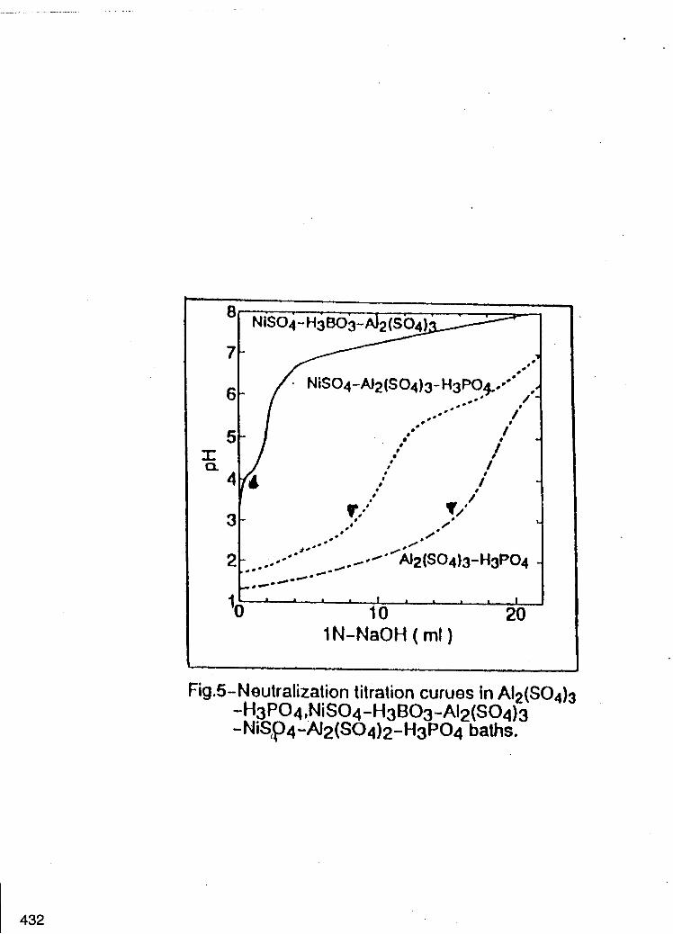
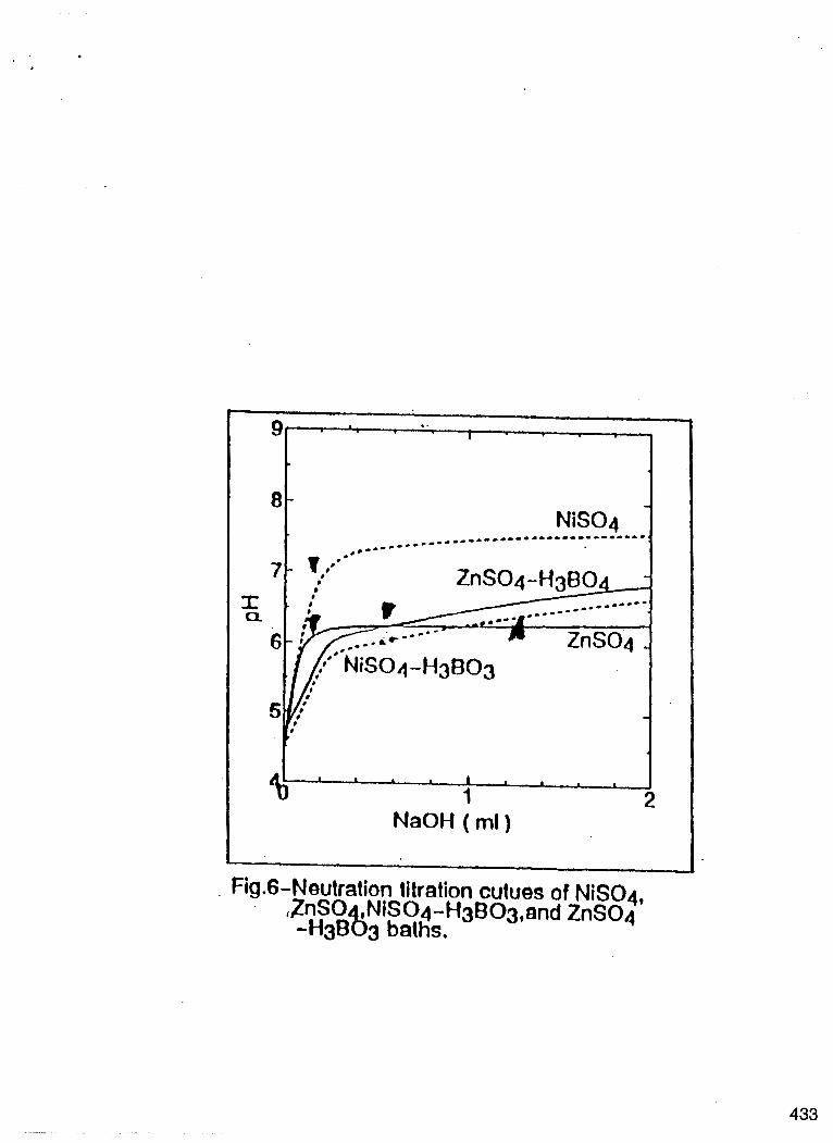
Neutralization curves of NiS04-H3B03 colouring bath.
Fig 3 shows three neutralization curves of the NiS04 bath the H3B03 bath, and the NiS04- H3B03 bath. The black triangle marks on the curves show the locations where precipitate of metal hydroxide was observed by naked eyes. The precipitation of Ni(OH)2 was observed at a pH of 6.8 in the NiS04 bath, whle the precipitate of Ni(OH)2 was generated at a pH of 6.2 in the NiS04-H3B03 bath. The Ph of Ni(OH)2 precipitation in the NiS04-H3B03 bath is lower compared to pH of precipitation in the NiS04- H3B03 bath is lower compared to pH of precipitation in the NiS04 bath. Therefore, it is assumed that nickel hydroxide is formed more easily in the NiS04-H3B03 bath than in the NiS04 bath, and the oxide film is assumed to be not coloured.However, the result of the electrolytic
colouring process contradicts this assumption. Anodized aluminum is not colourd in the NiSO4 bath and green precipitate deposits on the surface. The anodized aluminium is coloured in the NiS04- H3B03 bath because of the electrodeposition of nickel in the pores. This contradiction can be explained by the fact that the ease of formation of hydroxide in the pores does not depend on the pH value o f precipitation, hut on the titrated amount of NaOH for precipitation of metal ions. The precipitation of hydroxide with a small amount of NaOH means the precipitation of hydroxide by short time electrolysis.On the other hand precipitation of hydroxide with a large amount of NaOH implies the formation of hydroxide after a longer period of electrolysis.
When 0.01 ml of I N NaOH is titrated in the NiS04 bath, the pH of the solution increases to 6.8 and a precipitate of Ni(OH)2 is formed. This means that the pH of the solution in the pores increases rapidly to 6.8 and Ni(OH)L! precipitates by electrolysis in the NiS04 bath while the pH of the NiS04-H3B03 bath has a pH of 6.2 and green coloured precipitate is formed when 1. 16 ml of 1N NaOH is titrated in the NiS04-H3B03 bath. The amount of 1N NaOH required to generate a precipitate of Ni(OH)2 in the NiS04 bath. This shows that the time required to generate the precipitate of Ni(OH)2 in the pores of the anodic oxide film in the NiS04-H3B03 bath by cathodic current is 10.2 times greater than that in the NiS04 bath.
In other words, the precipitate of Ni(OH)2 is formed rapidly in the pores in the NiS04 bath and the precipitate of Ni(OH)2 is not formed in the pores until a longer time has elapsed in the NiS04- H3B03 bath and therefore, oxide film is coloured by electrodeposition of nickel in the pores. The results of titration of colouring bath and the results of electrolytic colouring coincide as explained
About the relationship between the colouring of oxide film and the neutralization curves of colouring baths, the amount of titrated NaOH required to precipitate hydroxide is more important than the pH value of the hydroxide precipitation.
above.
Neutralization curves of the colouring bath containing A12(S04)3.
Fig 4 shows the neutralization curves of the A12(S04)3 bath, the NiSW-H3B03 bath, and the
425

NiSO4-H3BO3-A12(SO4)3 bath. Al(OH)3 is formed at a pH of 3.8 in the A12(S04)3 bath. The precipitate of AI(OH)3 is formed at a pH of 4.1 in the NiS04-H3B03-A12(S04)3 bath. The titrated amounts of 1N NaOH are 0.63 d / i n the NiS04- H3B03-AI(S04)3 bath. The titrated amounts of 1N NaOH are 0.54 ml in the Al2(S04)3 bath and 0.27 ml in the NiS04-H3B03-A12(SO4)3 bath. The reason for the non colouring of the anodized aluminium in the colouring bath containing AI ions can be explained by comparing the titration curves of the NiS04-H3B03 bath and NiS04-H3B03- A12(S04)3 bath. In case of the NiS04-H3B03 bath, the precipitate of Ni(OH)2 is formed by titrating 1.10 ml of IN Na(OH), while the precipitate of AI(OH)3 is formed by titrating 0.26 ml of I N NaOH in the NiS04-H3B03-Al2(S04)3 bath. The results of the neutralization curve show that the oxide film is coloured lightly or not coloured at all in the colouring bath containing AI ions, because the precipitation of AI(OH)3 is formed just after the start of colouring electrolysis. Also, the results suggest a strict control of concentration of AI ions in the colouring bath to obtain the same shade for coloured films. The precipitate of AI(OH)3 is formed at a pH of 3.8 with 12.65 ml of I N NaOH in the AI(S04)3-H2S04 bath. ths result shows that AI(OH)3 is not formed easily in the SnS04-H2S04 bath, which is a popularly used colouring bath in European countries and the Unites States. In case of acidic tin sulphate colouring bath, the shades of coloured films are almost the same even if the concentration of AI ions is not controlled strictly.
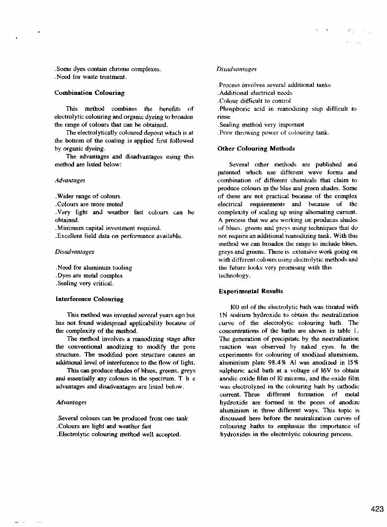
Neutralization curves of colouring bath containing H3P04
Fig 5 shows the neutralization curves of A12(S04)3-H3P04 bath NiS04-H3B03-A12(S04)3 bath and NiSO4-Al2(SO4)3-H3PO3 bath. Precipitate is formed at a pH of 3.0 in the A12(S04)3-H3P04 bath and also in the NiS04- A12(S04)3-H3P04 bath. The precipitate of Al(OH)3 is formed at pH 3.8 as shown fig 4. The precipitate formed in the A12(S04)3-H3P04 bath and in the NiS04-A12(S04)3-H3P04 bath is not Al(OH)3.For chemical conversion films of phosphate compound of Alp04 is formed at a pH 3.0. Therefore, the precipitate formed in the A12(S04)3-€€3PO4 bath and in the NiS04- Al2(S04)3-H3P04 bath is a compound of AlP04. This precipitate sediments rapidly in water, as the
compound consists o f tine crystalline particles. Therefor, even if the precipitate of Alp04 is formed in the pores of anodized aluminium,the decrease of cathodic current in the pores is small, Alp04 also is formed in the pores of anodized aluminium
re-anodizing. These oxides treated with H3P04 are colourrxl blue by electrolytic colouring. This special function of H3P03 treatment is due to the formation of AlP04 and AI(OH)3 is not formed by cathodic reaction. Therefore, metal can deposit uniformly in each pore and the colours film shows a blue colour.
Is well known that these blue colour films cannot be sealed by conventional sealing methods using hot water. The reason for h s is also due to the formation of Alp04 on the walls of the pores of anodized aluminium. Since reactions at the aluminium sites on the anodized aluminium have already occurred, a reaction with water to form a corrosion-resistant AI(OH)3 layer cannot occur.
__
treated with H3P04 by immersion treatment or by ~~
-
Novel colours by co-deposition of metal and metal hydroxide in the pores of anodized aluminium.
The addition o f MgS04 to the NiS04-H3B03 bath has been carried out since a long time in Japan. Stable production of light brown colour film is possible in this bath fig 7 shows the cathodic polarization curves in the NiS04-H3B03-MgS04 bath. The amount of MgS04 added to the colouring bath is changed from 0.3 gr/l to 35.0 gdl. There are three current peaks on the cathodic polarization curve. The first peak is due to the reduction of H ions. The second peak is due to the reduction of the dissolved oxygen in the colouring bath and the third peak is due to the reduction of Ni ions. When MgS04 is added to the colouring bath, only the third peak decreases. The deposition of nickel in the pores of anodized aluminium is suppressed by the precipitate of Mg(OH)2. However, even if more than IO gr/l of MgS04 is added to the colouring bath, the third peak does not decrease any more. This enable stable colouring of the oxide film to a light brown colour to be obtained.
Cathodic polarization curves of anodized aluminium in the NiSO4-H3BO3-Al2(S04)3 bath are shown in fig 8 for comparison. The larger the amount of A12(S04)3 in the colouring bath. The lower is third peak. The difference between these two polarization curves Fig 7 and fig 8 indicates
~
-
426

that Mg(OH)2 suppresses the nickel deposition moderately and Al(OH)3 suppresses the nickel deposition strongly. The codeposition of nickel and Mg(OH)2 enables light brown colouring to be obtained. Also, the co-deposition of metal and metal hydroxide enables novel colours to be obtained by the electrolytic colouring process.
Conclusion
When anodized aluminium is electrolyzed in the colouring bath, metal hydroxide deposits in the pores of the oxide film as a side reaction of metal deposition. Control of this metal hydroxide formation is very important for the AC colouring of anodized aluminium. This is important not only from the point of obtaining uniform colouring but also for development of novel colours by the
electrolytic colouring process.
References
G.E. Thompson and G.C. Wood, Nfltures, 290,230 (1981) T. Sato, Plot. atid Sut$ Fitr., 78, 74 (March 1991) E.B. Garriga, European patent 90309023.1 (1991) Sahm, P. R. and Hansen, P. N., Nurrrcricfll sitnulation arid modellirtg of casting and solidi~cntion pt-oces.sc.s for foundn and casthouse, CIATF, (1984) Wemcik, S. Pinner, R. and Sheasby, P.G. The Surface Treattnetrt nnd Finishing of Aluniinium and its Allovs, Ed., ASM, Ohio. Russ, J .C., Cotrrputer-Assisted Microscopy, The nreasurenrent rind Analysis of Images, Plenum Press, ( 1990)
427

Eloctrolyzing lime,rnin
Fig. 1 - Cathodic polarizatiori of anodized al umi nu r n at constant current density .

I
I I
I I
i I I I
I --7- --------- -------------
429

Fig.3- Neu tratiza t ion tit rat ion curues in H3SO3, NiSO4 and NiSO+H3€303 baths.
430

2 4 6 8 I ~ ' ! " ' ' ' ' 1N-NaOH ( ml ) - Fig.4-Neutralization titration curues in
N2(SOq)3 NiSOq-HgBO3,NiSOq - H ~ B O ~ - - A J ~ ( S O ~ ) ~ baths.
43 1
432
' * t
* #
0 *
i I i
I I I a I
10 20 1N-NaOH ( ml )
Fig .5 - N e u t r aliza t ion titration cur u e s in A12 (SO& -H3PO4 ,NiS04-H3B03-A12(SOq)3 -NiS,F)4-A12(S04)2-H3P04 baths.
E
7 T a
6
5
tO*= e
1 a a 1 1
1 1
NaOH (ml) 1
. Fig.6-Neutration titration cutues of NiS04, ZnSO NiSOq-H3BO=j,and ZnSO4 ‘ -Ha883 baths.
433

t -1.5
-1 J E s
I I 1
I ogn
1.0 gn 0.5 CJ/I
3.0 @ 5.0 Q/1 1 0 f l & 3 0 @
Voltage, v I
I
addition on I he ion cutves o in the NiSOq
-H3603 coloring bath.
' 434

, '
- .- I_
-1 1; o g n
3; 1.0 @I 4; 1.5 gn 5; 2.0 gA 6; 10gA
2; 0.5 g/i
0 Voltage, v
FIG.8-Effects of A12(SO4)3 addittion on Ihe cathodic olarlralion curves of anodize cf aluminum in the NiSOd -H3803 coloring bath.
435