Electrochemically primed functional redox mediator...
9
ARTICLE Electrochemically primed functional redox mediator generator from the decomposition of solid state electrolyte Matthew Li 1,2,3 , Zhengyu Bai 1 , Yejing Li 4 , Lu Ma 5 , Alvin Dai 3,6 , Xuefeng Wang 4 , Dan Luo 2 , Tianpin Wu 5 , Ping Liu 4 , Lin Yang 1 , Khalil Amine 3 , Zhongwei Chen 2 & Jun Lu 3 Recent works into sulfide-type solid electrolyte materials have attracted much attention among the battery community. Specifically, the oxidative decomposition of phosphorus and sulfur based solid state electrolyte has been considered one of the main hurdles towards practical application. Here we demonstrate that this phenomenon can be leveraged when lithium thiophosphate is applied as an electrochemically “switched-on” functional redox mediator-generator for the activation of commercial bulk lithium sulfide at up to 70 wt.% lithium sulfide electrode content. X-ray adsorption near-edge spectroscopy coupled with electrochemical impedance spectroscopy and Raman indicate a catalytic effect of generated redox mediators on the first charge of lithium sulfide. In contrast to pre-solvated redox mediator species, this design decouples the lithium sulfide activation process from the constraints of low electrolyte content cell operation stemming from pre-solvated redox mediators. Reasonable performance is demonstrated at strict testing conditions. https://doi.org/10.1038/s41467-019-09638-4 OPEN 1 School of Chemistry and Chemical Engineering, Key Laboratory of Green Chemical Media and Reactions, Ministry of Education, Henan Normal University, 453007 Xinxiang, China. 2 Department of Chemical Engineering, Waterloo Institute of Nanotechnology, University of Waterloo, 200 University Avenue West, Waterloo, ON N2L 3G1, Canada. 3 Chemical Sciences and Engineering Division, Argonne National Laboratory, 9700 Cass Avenue, Lemont, IL 60439, USA. 4 Department of NanoEngineering, University of California San Diego, 9500 Gilman Drive, La Jolla, CA 92093, USA. 5 X-ray Science Division, Advanced Photon Source, Argonne National Laboratory, 9700 Cass Avenue, Lemont, IL 60439, USA. 6 Department of Macromolecular and Science and Engineering, School of Engineering, Case Western Reserve University, 2100 Adelbert Road, Cleveland, OH 44106, USA. Correspondence and requests for materials should be addressed to Z.B. (email: [email protected]) or to Z.C. (email: [email protected]) or to J.L. (email: [email protected]) NATURE COMMUNICATIONS | (2019)10:1890 | https://doi.org/10.1038/s41467-019-09638-4 | www.nature.com/naturecommunications 1 1234567890():,;
Transcript of Electrochemically primed functional redox mediator...

ARTICLE
Electrochemically primed functional redox mediatorgenerator from the decomposition of solid stateelectrolyteMatthew Li1,2,3, Zhengyu Bai1, Yejing Li4, Lu Ma 5, Alvin Dai3,6, Xuefeng Wang4, Dan Luo2, Tianpin Wu5,
Ping Liu 4, Lin Yang1, Khalil Amine 3, Zhongwei Chen 2 & Jun Lu 3
Recent works into sulfide-type solid electrolyte materials have attracted much attention
among the battery community. Specifically, the oxidative decomposition of phosphorus and
sulfur based solid state electrolyte has been considered one of the main hurdles towards
practical application. Here we demonstrate that this phenomenon can be leveraged when
lithium thiophosphate is applied as an electrochemically “switched-on” functional redox
mediator-generator for the activation of commercial bulk lithium sulfide at up to 70 wt.%
lithium sulfide electrode content. X-ray adsorption near-edge spectroscopy coupled with
electrochemical impedance spectroscopy and Raman indicate a catalytic effect of generated
redox mediators on the first charge of lithium sulfide. In contrast to pre-solvated redox
mediator species, this design decouples the lithium sulfide activation process from the
constraints of low electrolyte content cell operation stemming from pre-solvated redox
mediators. Reasonable performance is demonstrated at strict testing conditions.
https://doi.org/10.1038/s41467-019-09638-4 OPEN
1 School of Chemistry and Chemical Engineering, Key Laboratory of Green Chemical Media and Reactions, Ministry of Education, Henan Normal University,453007 Xinxiang, China. 2 Department of Chemical Engineering, Waterloo Institute of Nanotechnology, University of Waterloo, 200 University AvenueWest, Waterloo, ON N2L 3G1, Canada. 3 Chemical Sciences and Engineering Division, Argonne National Laboratory, 9700 Cass Avenue, Lemont, IL 60439,USA. 4Department of NanoEngineering, University of California San Diego, 9500 Gilman Drive, La Jolla, CA 92093, USA. 5 X-ray Science Division, AdvancedPhoton Source, Argonne National Laboratory, 9700 Cass Avenue, Lemont, IL 60439, USA. 6 Department of Macromolecular and Science and Engineering,School of Engineering, Case Western Reserve University, 2100 Adelbert Road, Cleveland, OH 44106, USA. Correspondence and requests for materials shouldbe addressed to Z.B. (email: [email protected]) or to Z.C. (email: [email protected]) or to J.L. (email: [email protected])
NATURE COMMUNICATIONS | (2019) 10:1890 | https://doi.org/10.1038/s41467-019-09638-4 |www.nature.com/naturecommunications 1
1234
5678
90():,;

The class of sulfide-type solid electrolyte (STSSE) materialshas gained significant interest among the solid-state elec-trolyte community1–4. Their tendency to possess higher Li-
ion conduction and possibilities of low temperature synthesis(when compared to the next leading solid electrolyte material)5
makes them one of the most promising candidate for solid-statebatteries6. Recent research into the STSSE has placed a spotlighton the electrochemical stability of STSEE. Thermodynamically,STSSEs are known to be unstable at the voltage range of interestfor both cathode and anode electrodes7,8. Specifically, the natureof the interface layer (i.e., the degree and type of passivation)between the STSSE and active material strongly dictates thelongevity of a solid-state cell9,10. With so much knowledge gainedon the decomposition process of STSSE, it is timely to examinecross-field applications of this phenomenon. Some of the ther-modynamically predicted oxidation decomposition products(particularly in the case of redox-active products8,11,12) of P- andS-containing STSSE can be quite useful for liquid battery systemswhere redox mediators are needed13. Furthermore, as theseproducts are only produced when the STSSE is oxidized, it canpresent itself as an in situ generator of chemical species that canbe “switched-on” at specific oxidation voltages.
A highly applicable area for these functional redox mediators isthe sulfur-based battery chemistries14,15. As a promising cathodematerial for Li-S or S-based Li-ion batteries, Li2S can not onlysupply a source of Li ions but can also mitigate the volumeexpansion concerns of the sulfur electrodes. With a specific Li-ioncapacity of over 1100mAh g−1, Li2S has drawn much recentattention in the research community. While the benefits are clear16,Li2S presents a very high initial activation barrier for the firstcharge, which stems from the strong ionic bonds within its crystaland the nucleation barrier of forming solvated polysulfide species17.Such a hurdle (often reaching >4.2 V vs. Li+/Li) typically results inlow specific capacity and electrolyte decomposition leading to poorcycle stability. Strategies used to solve these problems typically fallinto two categories: carefully designed nano-sized Li2S compositematerial18,19 or electrolyte additive in the form of pre-solvatedredox mediators17,20. While both of these strategies have shownsignificant progress in reducing the charge overpotential andachieving good overall performance, they also introduce significantdisadvantages. Novel Li2S composite materials typically requireexotic synthesis environments composing of high temperatures ortoxicity, while soluble redox mediators often introduced into theelectrolyte will contribute to severe internal shuttling and inevitablydepend on the volume of electrolyte used. Furthermore, the use ofpre-solvated redox mediators will likely deteriorate in effectivenessif the cells are not immediately charged after assembly, conflictingwith the electrolyte wetting process. Moreover, the commonly usedexcess amounts of high oxidation state polysulfides as redox med-iators will result in an overall low amount of starting Li ion from thecathode (for a full cell Li2S-based lithium ion battery (LIB)). Anideal solution to these challenges is the use of an initially dormantredox mediator that remains inactive during the electrolyte wettingprocess, effective at low mass ratios, separate from the electrolyte todecouple from the effect of electrolyte volume, and only activateswhen the first charge is initiated.
In this work, we demonstrate that the oxidative decompositionof solid Li3PS4 (lithium thiophosphate (LPS)) can be leveraged asa redox mediator generator that is electrochemically “switched-on” for lowering the first charge overpotential of commercial Li2S.Crucially, the observed enhancements in performance areachieved with only the direct simple mixing of LPS into the slurryformulation at 10 wt.%. This is the first reported use of a solidmaterial as a redox mediator source. We have shown that thismaterial will not dissolve into the electrolyte unless activated, andas such, less dependent on the volume of electrolyte used.
ResultsDisadvantage of pre-solvated redox mediator: lithium poly-sulfide. Electrolytes preloaded with soluble redox mediators havebeen widely used as Li2S activators throughout literature17,20,21.Taking lithium polysulfide (LiPS) as the representative additive, itis clear that the use of Li2S8 as redox mediator is only applicablewhen significant amounts of Li2S8 are added (SupplementaryFigure 1a, arrows indicates the theoretical amount of Li ion that isextractable from each specific ratio of Li2S to Li2S8). For anelectrode based on a 60 wt.% commercial Li2S, it was found thatthe ratio of Li2S8 to Li2S must be raised to a relatively high(30–60 wt%) to achieve significant improvements to the chargevoltage profile. It should be noted that this is not the result of adecreased current density (normalized to loaded Li2S mass) asexperiments at half the current still maintains a very high chargevoltage (Supplementary Figure 1b). It is important to rememberthat one of the most advantageous aspect of using Li2S over Sis its ability to serve as a source of Li ions, that is, pairing with aLi-ion-free anode. It is then foreseeable that the use of significantamounts of LiPS to activate Li2S will result in a delithiatedcathode with excess amounts of sulfur that cannot be lithiated inthe subsequent cycle without another source of Li-ions. Addi-tionally, every sample with soluble polysulfide species experiencedhigher than theoretical charge specific capacity (theoretical indi-cated by arrowheads) likely suggesting shuttling22. This is parti-cularly evident in cells (LiPS:Li2S= 30:70) cycled at decreasedcurrent density (Supplementary Figure 1c), yielding a first chargecapacity of well over 2500 mAh g−1 normalized to the sulfurcontent even with 0.5 M LiNO3. Finally, changes to the electrolytecontent also dramatically influences the chargeability of theelectrode. When the total electrolyte content is tuned down to~7 μLmg− 1
Li2S(maintaining a constant LiPS:Li2S ratio), there is a
dramatic decrease in specific capacity and corresponding increasein charge potential. Therefore, a Li2S-based LIB that utilizespolysulfide in amounts such that it serves as an efficient Li2Sactivator and under low electrolyte conditions, will be practicallyunlikely.
Electrochemical properties of LPS and its application in com-mercial Li2S cathodes. The specific LPS solid electrolyte com-position has drawn a lot of interest due to its high ionicconductivity at room temperature and ease of synthesis2,23. Thestability of LPS has been a topic of great concern in the field ofsolid electrolyte24–26. It is often considered that the electro-chemical decomposition of LPS complicates its application as asolid-state Li-ion conductor. Due to its redox activity at apotential window similar to that of Li2S8, it would be interestingto revisit the stability of LPS, but in a liquid electrolyte setting.With a similar but slightly higher oxidation voltage than Li2S, itcould be a perfect source of redox mediators for Li2S activation.Figure 1a displays the cyclic voltammograms of LPS in common1,3 dioxolane/dimethoxymethane-based Li-S electrolyte. A pro-nounced anodic peak is found at ~2.7 V and then at ~3.4 Vduring its initial delithiation sweep (in blue). The followingcathodic and subsequent anodic sweep (in black) furtherdemonstrated its redox activity in Li-S electrolyte. Corroboratingthese data, constant current delithiation of LPS at 0.1 mAmg−1
produces a sloped plateau from ~2.7 to 3.1 V (Fig. 1b) followed byanother plateau at ~3.2 and 3.6–4.0 V. While these results areintriguing and produced apparently more pronounced voltageprofiles from traditional solid-states studies of LPS27, the mostimportant phenomenon of LPS can only be revealed whencharged without LiNO3 present in the electrolyte. Cells chargedwith LiNO3 yielded ~250 mAh g−1
LPS, whereas cells withoutLiNO3 (commonly used to prevent shuttling28) required more
ARTICLE NATURE COMMUNICATIONS | https://doi.org/10.1038/s41467-019-09638-4
2 NATURE COMMUNICATIONS | (2019) 10:1890 | https://doi.org/10.1038/s41467-019-09638-4 | www.nature.com/naturecommunications
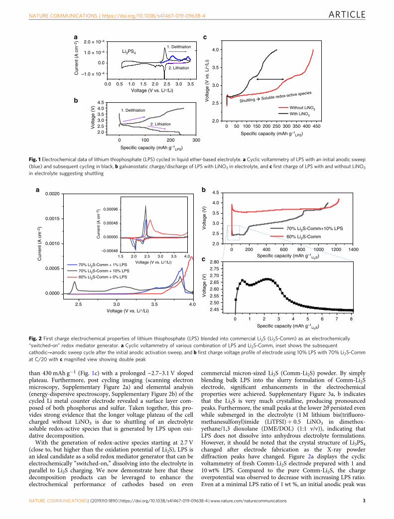
than 430 mAh g−1 (Fig. 1c) with a prolonged ~2.7–3.1 V slopedplateau. Furthermore, post cycling imaging (scanning electronmicroscopy, Supplementary Figure 2a) and elemental analysis(energy-dispersive spectroscopy, Supplementary Figure 2b) of thecycled Li metal counter electrode revealed a surface layer com-posed of both phosphorus and sulfur. Taken together, this pro-vides strong evidence that the longer voltage plateau of the cellcharged without LiNO3 is due to shuttling of an electrolytesoluble redox-active species that is generated by LPS upon oxi-dative decomposition.
With the generation of redox-active species starting at 2.7 V(close to, but higher than the oxidation potential of Li2S), LPS isan ideal candidate as a solid redox mediator generator that can beelectrochemically “switched-on,” dissolving into the electrolyte inparallel to Li2S charging. We now demonstrate here that thesedecomposition products can be leveraged to enhance theelectrochemical performance of cathodes based on even
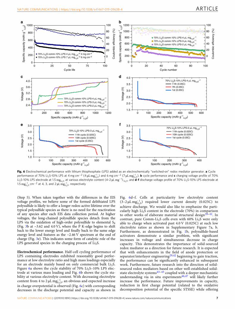
commercial micron-sized Li2S (Comm-Li2S) powder. By simplyblending bulk LPS into the slurry formulation of Comm-Li2Selectrode, significant enhancements in the electrochemicalproperties were achieved. Supplementary Figure 3a, b indicatesthat the Li2S is very much crystalline, producing pronouncedpeaks. Furthermore, the small peaks at the lower 2θ persisted evenwhile submerged in the electrolyte (1 M lithium bis(trifluoro-methanesulfonyl)imide (LiTFSI)+ 0.5 LiNO3 in dimethox-yethane/1,3 dioxolane (DME/DOL) (1:1 v/v)), indicating thatLPS does not dissolve into anhydrous electrolyte formulations.However, it should be noted that the crystal structure of Li3PS4changed after electrode fabrication as the X-ray powderdiffraction peaks have changed. Figure 2a displays the cyclicvoltammetry of fresh Comm-Li2S electrode prepared with 1 and10 wt% LPS. Compared to the pure Comm-Li2S, the chargeoverpotential was observed to decrease with increasing LPS ratio.Even at a minimal LPS ratio of 1 wt %, an initial anodic peak was
0.0 0.5 1.0 1.5 2.0 2.5 3.0 3.5
0.0
1. Delithiation
2. Lithiation
0 100 200 300
2.02.53.03.54.04.5
Vol
tage
(V
)
1. Delithiation
a
b
0 50 100 150
Soluble redox-active species
Shuttling
200 250 300 350 400 4502.0
2.5
3.0
3.5
4.0
Without LiNO3
With LiNO3
Li3PS4
c
2. Lithiation
Cur
rent
(A
cm
–2) 2.0 × 10⁻⁴
1.0 × 10⁻⁴
–1.0 × 10⁻⁴
Voltage (V vs. Li+/Li)
Vol
tage
(V
vs.
Li+
/Li)
Specific capacity (mAh g–1LPS)
Specific capacity (mAh g–1LPS)
Fig. 1 Electrochemical data of lithium thiophosphate (LPS) cycled in liquid ether-based electrolyte. a Cyclic voltammetry of LPS with an initial anodic sweep(blue) and subsequent cycling in black, b galvanostatic charge/discharge of LPS with LiNO3 in electrolyte, and c first charge of LPS with and without LiNO3
in electrolyte suggesting shuttling
0 200 400 600 800 1000 1200 14002.0
2.5
3.0
3.5
4.0
4.5
Vol
tage
(V
)
Specific capacity (mAh g–1Li2S)
Specific capacity (mAh g–1Li2S)
70% Li2S-Comm+10% LPS
60% Li2S-Comm
2.5 3.0 3.5 4.0
0.0000
0.0005
0.0010
0.0015
0.0020
1.5 2.0 2.5 3.0 3.5 4.0–0.00048
0.00000
0.00048
0.00096
Cur
rent
(A
cm
–2)
70% Li2S-Comm + 1% LPS
70% Li2S-Comm + 10% LPS
60% Li2S-Comm + 0% LPS
Cur
rent
(A
cm
–2)
Voltage (V vs. Li+/Li)
0 1 2 3 4 5 6 7 8
2.45
2.50
2.55
2.60
2.65
2.70
2.75
2.80
Vol
tage
(V
)
Voltage (V vs. Li+/Li)
a b
c
Fig. 2 First charge electrochemical properties of lithium thiophosphate (LPS) blended into commercial Li2S (Li2S-Comm) as an electrochemically“switched-on” redox mediator generator. a Cyclic voltammetry of various combination of LPS and Li2S-Comm, inset shows the subsequentcathodic→anodic sweep cycle after the initial anodic activation sweep, and b first charge voltage profile of electrode using 10% LPS with 70% Li2S-Commat C/20 with c magnified view showing double peak
NATURE COMMUNICATIONS | https://doi.org/10.1038/s41467-019-09638-4 ARTICLE
NATURE COMMUNICATIONS | (2019) 10:1890 | https://doi.org/10.1038/s41467-019-09638-4 |www.nature.com/naturecommunications 3

found at 3.5 V with a subsequent peak at 3.8 V, which is lowerthan the ~4.0 V required to obtain an oxidative peak for the pureComm-Li2S electrode. At 0.05C, the charge voltage of Comm-Li2Swas dramatically decreased (Fig. 2b) even with an increased Li2Scontent. It is also worth mentioning that there appears to be adouble activation peak as shown in Fig. 2c. We believe the first isthe initial “switching-on” process of LPS, followed by itsactivation (second peak) of the bulk Li2S assisted by the oxidationproducts of LPS. After the initial activation process, there is aninitial plateau followed by a sloped second plateau and a thirdplateau at the higher voltage region. The segregation of theseplateaus is likely related to the different activation processes ofLi2S with LPS. For example, the initial plateau could be due to thehigher concentration of redox mediators, while the second slopedplateau could be an indication of a gradual decline in redoxmediator concentration.
The role of LPS in Li2S activation. Electrochemical impedancespectroscopy (EIS) reveals substantial differences between elec-trode with and without LPS. Figure 3a, b shows the voltage profileduring the operando EIS experiment of Comm-Li2S at 60% inblack and Comm-Li2S at 70% with 10% LPS in red, respectively.It should be noted that the voltage profile of the EIS process variesfrom the pure galvanostatic charge process likely due to thedynamic nature of soluble species created. Although EIS processeshave been considered mostly non-invasive in most studies, thisresult reveals a clear reduction in effectiveness in LPS’s activationof Li2S. Furthermore, there also appears to be an apparentrequirement of the pure Comm-Li2S cells to reinitiate its activa-tion process with a sharp peak after each EIS data collectionsession (Fig. 3a). This shows that the activation process of Li2S isvery time dependent likely with concurrent processes competingfor polysulfide (out-of-cathode diffusion and anode corrosion)29.
Regardless, important differences in impedance are stillobserved. The Nyquist plot of the collected EIS data of pureLi2S-Comm electrode is shown in Fig. 3c–e and of the 70% Li2S-Comm blended with 10% LPS electrode in Fig. 3f–h. As theimpedance features of this material varies significantly withfrequency, different axis range/magnifications are shown forclarity. Consistently throughout the first charge, a small semi-circle was found at the high-frequency range followed by a verylarge mid-frequency semi-circle, which we allocated to interfacialand charge transfer resistance, respectively, according to previoustemperature-based studies30. Based on this, all Nyquist plots werefitted as shown in Fig. 2i (corresponding simulated andexperimental Bode plot can be found in Supplementary Figure 4a,b, respectively). Each impedance spectrum was fitted to the circuitshown in inset of Fig. 2i18,31–33. Initially, the interfacial resistanceappeared to be higher for the cells with LPS (Fig. 3j). This couldbe attributed to the higher ratio of non-conductive material (LPSand Li2S) to carbon as the Li2S content is 70% in the electrodecontaining LPS, whereas the electrode without LPS has only 60%.Interestingly, after the initial activation process, the interfacialresistance of the LPS-containing electrode dropped drasticallyfrom ~105 to ~10Ω. This is in contrast to the pure 60% Li2Selectrode where it exhibited only a modest decrease throughoutthe course of charge. Additionally, the charge transfer resistance(mid-frequency semi-circle) initially started higher once again forthe LPS-containing electrode, but was exceeded by the pure Li2Selectrode near the end of the charge period (~650mAh g−1) asshown in Fig. 3k. This is intriguing because the enormous chargetransfer resistance of the LPS-containing electrode is not reflectedin the charging voltage profile. As the impedance spectroscopywas taken at potentiostatic conditions after a rest period (i.e.,spectrum collection voltage is close to open-circuit voltage (OCV)at each specific state of charge), the resulting current responseoscillates around near 0 mA. This suggests that there is a very
k
0
2000
4000
6000
8000
10,000
Cha
rge
tran
sfer
resi
stan
ce, R
ct (
Ω)
0 500 1000 15000
500
1000
1500
2000
Experimental Simulated
2.02.53.03.54.0
Vol
tage
(V
)
0 25,000 50,000 75,000 100,0002.02.53.03.54.0
Vol
tage
(V
)
Time (s)
0 25,000 50,000 75,000 100,000
Time (s)
b
e
a
0 300 600 900 1200 15000
–300
–600
–900
–1200
–1500
0 25 50 75 100
–20
–402.41132.5072.46722.45892.45722.45782.45972.4632.46712.47372.48282.49432.50592.51822.52932.552.57022.58782.5992.61122.61842.63132.6442.6642.69462.74232.8071
0 3400 6800 10,200
0
–5000
–10,000
–15,000
–20,000
Zim
Zim
Zim
Zim
Zim
Zim
0
1000
2000
3000
4000
5000
6000
0
–1000
–2000
–3000
–4000
–5000
0 610 1220 1830
0
–410
–820
–1230
0 25 50 75 100
0
–14
–28
–42
2.2732
2.387
2.4891
2.6506
2.6492
2.6311
2.6216
2.6086
2.5976
2.6078
2.6181
2.6095
2.5994
2.5964
2.6122
2.6464
2.6901
2.7458
2.7939
f g h
c d
i
0 100 200 300 400 500 600 700 800 9000
20
40
60
80
100
Inte
rfac
ial r
esis
tanc
e, R
int (
Ω)
Rs Rint Rct W
CPE2CPE1
Z real
Z real
Z real Z real
Z real Z real
ZIm
(Ω
)
ZRe (Ω)
70% Li2S-Comm + 10% LPS
60% Li2S-Comm
70% Li2S-Comm + 10% LPS
60% Li2S-Comm
Specific capacity (mAh g–1)
0 100 200 300 400 500 600 700 800 900Specific capacity (mAh g–1)
j
Fig. 3 Electrochemical impedance spectroscopy (EIS) study. Voltage profile of EIS experiment of a the commercial Li2S (Li2S-Comm) electrode and b the70% Li2S-Comm blended with 10% lithium thiophosphate (LPS) electrode. c–e Corresponding Nyquist plot of the Li2S-Comm electrode and f–h 70% Li2S-Comm blended with 10% LPS electrode at different axis ranges. The color legend is labeled in V. i Example of experimental and simulated Nyquist plot,j interfacial resistance (high-frequency semicircle) and k plot of charge transfer resistance (mid-frequency semicircle) of Comm-Li2S (black) and withLPS (red)
ARTICLE NATURE COMMUNICATIONS | https://doi.org/10.1038/s41467-019-09638-4
4 NATURE COMMUNICATIONS | (2019) 10:1890 | https://doi.org/10.1038/s41467-019-09638-4 | www.nature.com/naturecommunications

strong dependence of the charge voltage on the presence of anapplied current. It is further intriguing that for the pure Li2Selectrode, after each rest period and subsequent EIS spectrumanalysis, there is a reactivation process indicating a depletion ofpolysulfide from the previous current-halt period (rest time andEIS analysis). This is not present in the first ~400 mAh g−1 ofcharge for the electrodes with LPS. Accordingly, the contradictionbetween the higher charge voltage and lower apparent impedanceof the LPS-containing electrode is likely due to good chargetransfer kinetics of polysulfide and its role in the comproportio-nation reaction with Li2S34. However, because there is a constantneed of the pure Comm-Li2S electrode to generate polysulfidespecies that are quickly consumed (by other polysulfidecompeting processes29). This creates a situation where thepolysulfides cannot properly react with the remaining Li2S, andas such, the voltage remains high. Whereas in the case of the LPS-containing electrode, the lack of an activation process after eachEIS analysis indicates significantly higher amounts of solublemediators that are generated with longer lifetime, serving a moreprolonged role in mediating the charge process of the bulk Li2Sparticles.
To clarify the mechanism of LPS on the charging process ofLi2S, ex situ X-ray absorption near-edge structure (XANES) was
conducted. As indicated on Fig. 4a, six spectra were measuredat six different states of charge. Specifically, cells weredisassembled and analyzed at OCV= ~2.42, ~2.43, ~2.46,~2.91, ~3.62, and 4.0 V. Overall, the S K-edge was found tochange considerably over the course of the first charge (Fig. 4b).From OCV to ~2.46 V, the overall characteristics of the S K-edge remained relatively the same where the convex shape ofthe Li2S aligns well with the literature35. However, in themagnified view (Fig. 4c), it can be seen that the polysulfideshoulder (~2468 eV, matching our polysulfide standard mea-surement) increases from the fresh cell at OCV (Fig. 4c, blackcurve) to the cell at ~2.46 V (Fig. 4c, blue). Interestingly, thepolysulfide species were not detected at the lower state of chargeof ~2.43 V (Fig. 4c, dark blue), whereas a change in the P K-edge was detected early in the charge process (~2.43 V, Fig. 4d,e). This strongly suggests that the initial activation process ofLi2S is not due to the formation of polysulfide35. At highervoltages (~3.62 V) the spectrum largely resembles that of thesulfur standard sample (Fig. 4b), where the convex shape of Li2Schanges to concave at ~2474 eV as previously reported35. Infact, the convex shape of Li2S cannot be found even at ~2.91 V,suggesting that a large majority of it has been consumed, that is,likely successfully oxidized. This is also seen in the ex situ
0100200300400500600700800900
100011001200
Spe
cific
cap
acity
(m
Ah
g–1Li
2S)
Voltage (V)
S K-edge
Charge
Li2S4 solution
Solid P2S5
S8
2
4
6
8
10
0.0
0.5
1.0
1.5
2.0
2.5
Nor
mal
ized
xμ
(E)
Nor
mal
ized
xμ
(E)
Energy (eV) Energy (eV)
Li2S4
S K-edge
Li2S4 reference sample
ChargeOCV
~2.43 V
~2.46 V
~2.91 V
~3.62 V
4.0 V
~2.43 V~2.46 V
~2.91 V
~3.62 V
4.0 V
OCV
2130
2467
.424
504.0
3.6
3.2
2.8
2.4
2475
2500
2468
.7
2470
.0
2471
.321
4021
5021
6021
70
0
5
10
15
20
Energy (eV)
P K-edge
Solid P2S5
Charge
~2.43 V
~2.46 V
~2.91 V
~3.62 V
4.0 V
OCV
2147.0 2156.5 2166.0 2175.5
0.0
0.5
1.0
1.5
2.0
2.5
3.0
3.5
4.0
~2.46 V4.0V
Energy (eV)
2142.0 2145.5 2149.0 2152.5 2156.0
0.0
0.5
1.0
1.5
2.0
2.5
3.0
3.5OCV~2.43 V
Energy (eV)
Nor
mal
ized
xμ
(E)
Nor
mal
ized
xμ
(E)
a b c d
e f
Fig. 4 Ex situ X-ray adsorption near edge spectroscopy study of lithium thiophosphate (LPS) containing Li2S electrodes at various voltage throughout thefirst charge. a Voltage profile of the first charge (0.05C) of 70% commercial Li2S (Li2S-Comm)+ 10% LPS, where the circles indicate the specific capacity/voltage at which each ex situ X-ray absorption spectroscopy (XAS) measurement was conducted. b S K-edge of electrode taken at different states ofcharge with spectra of homemade Li2S4 solution, commercial P2S5 and commercial S8 as a reference. c Magnified S K-edge of electrode opened at: freshand ~2.46 V. d P K-edge of electrodes taken at different states of charged in addition to commercial P2S5 as reference. e Overlay of P K-edge at OCV and~2.43, with the arrow indicating the increase in near edge features and f ~2.46 and 4.0 V displaying highly similar features at the beginning (~2.46 V) andend of charge (4.0 V)
NATURE COMMUNICATIONS | https://doi.org/10.1038/s41467-019-09638-4 ARTICLE
NATURE COMMUNICATIONS | (2019) 10:1890 | https://doi.org/10.1038/s41467-019-09638-4 |www.nature.com/naturecommunications 5

Raman spectroscopy (Supplementary Figure 5) of the sameelectrodes where the peak at ~365 cm−1 (likely Li2S) shifts to354 cm−1 from ~2.43 to ~2.46 V whereupon it completelydisappears at voltages above ~2.46 V. At 4.0 V, the spectrumfurther evolves into a shape different to that of the S8 standardsample. The origin of this pattern is however unclear, but webelieve it might be some phosphorus-based sulfur speciessuperimposed by elemental sulfur signals as theoreticallypredicted by the high voltage decomposition of Li3PS48.Surprisingly, the P K-edge of the sample at 4.0 V did notexhibit features similar to the P2S5 standard (Fig. 4d). This isalso seen in the Raman data where the originally formed~246.5 cm−1 at the ~3.62 V transforms into a double peakcentered at ~241 and 264 cm−1 at 4.0 V (SupplementaryFigure 5), not present in the commercial orthorhombic sulfursample36. It is worth noting that P2S5 is one of thethermodynamically predicted oxidation products of LPS athigh voltage8.
It is important to note the difference between our XANES dataand other previous reports on the delithiation of LPS in a solid-state configuration27. While the initial P K-edge features of ouroriginal OCV samples are near identical (Fig. 4e) to the literature,the XANES feature differed quite drastically upon delithiation inour work. In the solid-state configuration, the P K-edge wasreported to remain mostly constant throughout delithiation withonly decrease in the edge-peak height coupled with a generalincrease of the broad peaks at higher energy levels. Interestingly,an analogous process of decreasing the synthesis molar ratio ofLi2S:P2S5 (LPS, molar equivalent of 75 Li2S:25 P2S5), that is,decreasing the proportion of Li, have also been reported to yield asimilar decrease in peak height37. In contrast to these works, the PK-edges in this work (Fig. 4d) exhibited a complete edge shifttowards a higher energy level of electrodes harvested from OCVto ~2.91 V and then an edge shift back to a lower energy levelfrom ~2.91 to 4.0 V, in addition to significant changes in thespectrum’s shape at the near edge. Only in the initial stage ofcharging did the P K-edge exhibited a slight increase in the nearedge features and decrease in edge height (Fig. 4e) similar to theaforementioned literature. The spectrum taken at ~2.46 V alreadyreveals a major change in shape, suggesting changes to thebonding environment of P have occurred. Subsequent samplemeasurements at higher voltages continued to produce
pronounced changes to both the edge position and shape. Thepeak features at ~2151 and ~2167 eV might be related P2O5
present in the sample as shown in the comparison withcommercial P2O5 experimental data (Supplementary Figure 6).As both peaks are consistently present among all the P K-edgespectrum, one might claim it is due to air contamination duringmeasurement. However, the complete dominance of these higherenergy peaks at ~3.17 V and its shift back towards lower energylevels for spectra taken at ~3.62 and ~4.0 V might indicate thatthis is not solely due to air contamination. Conversely, we believethe peak at ~3.17 V is related to the voltage and charging processof Li2S with LPS. Since chemical reactions between Li3PS4 and S8have been reported literature, where the physical mixing of LPSwith S8 have yielded Li polysulfidophosphates38. We propose thatthe higher energy levels observed from electrodes harvested at~2.91 to ~3.62 V is due to some bonding of P with long-chained Sspecies. With more sulfur species attached to each P atom, theelectron cloud should shift away from P, subsequently increasingthe excitation energy required for the P 1s core level. It should benoted that this is only our interpretation of our data and anotherchemical process could be occurring. Regardless of the truechemical interaction mechanism of LPS, even more interesting isthat at the end of charge, that is, spectrum taken at 4.0 V, theXANES spectrum almost reverts completely back to the featuresof the sample taken at ~2.46 V (Fig. 4f). This suggests that thedecomposed LPS performed a catalytic role. Because it does notrevert to the same form as the spectrum taken at OCV or ~2.43 V,we believe the observed edge shifts toward a higher energy levelfor electrodes harvested from OCV to ~2.43 V could be anindication of an initial priming (“switching-on”) process ofthe LPS.
Proposed mechanism. Overall, the LPS initially delithiated, thatis, “switched-on”, producing soluble redox active products andactivating Li2S as shown in Step 1 of the schematic drawn inFig. 5. The soluble redox-active products then migrated to thebulk crystalline Li2S (Step 2) where it helped generate polysulfidespecies (Step 3). This is also supported by the double activationpeak shown in Fig. 2c. To follow, we believe the P from thedelithiated LPS bonded with sulfur-based species (likely highordered polysulfides, Step 4), stabilizing it for subsequent use incomproportionation reactions with the remaining Li2S particles
BulkLi2S
Bulk LPS
e–
Li+
Conductive support
LPS polysulfide
Sn2–
e–
Step: 1
Step: 2
Step: 3
Step: 4Step: 5
Lin<3PXSy–
Fig. 5 Schematic of proposed Li2S activation mechanism. Step 1: lithium thiophosphate (LPS) is delithiated generated soluble redox active P,S-basedspecies. Step 2: These species diffuse to the surface of bulk Li2S, where it (Step 3) reacts via comproportionation. Step 4: The delithiated LPS form some ofreversible compound with polysulfide. Step 5: The LPS-polysulfide compound is then used to further comproportionation with Li2S
ARTICLE NATURE COMMUNICATIONS | https://doi.org/10.1038/s41467-019-09638-4
6 NATURE COMMUNICATIONS | (2019) 10:1890 | https://doi.org/10.1038/s41467-019-09638-4 | www.nature.com/naturecommunications
(Step 5). When taken together with the differences in the EISvoltage profiles, we believe some of the formed delithiated LPSpolysulfide is likely to offer a longer redox-active lifetime over thetypical polysulfide species as there is no need for the reactivationof any species after each EIS data collection period. At highervoltages, the long-chained polysulfide species detach from theLPS via the oxidation of high-order polysulfide to elemental S8(Fig. 3b at ~3.62 and 4.0 V), where the P K-edge begins to shiftback to the lower energy level and finally back to the same edgeenergy level and features as the ~2.46 V spectrum at the end ofcharge (Fig. 3e). This indicates some form of catalytic role of theLPS generated species in the charging process of Li2S.
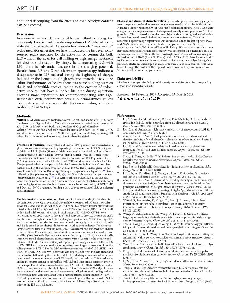
Electrochemical performance. Half-cell cycling performance ofLPS containing electrodes exhibited reasonably good perfor-mance at low electrolyte ratio and high mass loadings especiallyfor an electrode mainly based on only commercial bulk Li2S.Figure 6a shows the cycle stability of 70% Li2S–10% LPS elec-trode at various mass loading and Fig. 6b shows the cycle sta-bility at various electrolyte content. With decreasing electrolytecontent from 4 to 2 μLmg− 1
Li2S, an obvious and expected increase
in charge overpotential is observed (Fig. 6c) with correspondingdecreases in the discharge potential and capacity as shown in
Fig. 6d–f. Cells at particularity low electrolyte content(3–2 μLmg− 1
Li2S) required lower current density (0.025C) to
achieve discharge. We would also like to emphasize the parti-cularly high Li2S content in the electrode (70%) in comparisonto other works of elaborate material structural design39–41. Incontrast, pure Comm-Li2S cells even with 60% Li2S were onlyable to charge when activated past 4.0 V (0.025C) at such lowelectrolyte ratios as shown in Supplementary Figure 7a, b.Furthermore, as demonstrated in Fig. 1b, polysulfide-basedactivators demonstrate a similar problem, with significantincreases in voltage and simultaneous decrease in chargecapacity. This demonstrates the importance of solid-sourcedredox mediator as a direction for future research. It is expectedthat with enhancements in the field of anode protection orseparator/interlayer engineering29,42 beginning to gain traction,the performance can be significantly enhanced in subsequentwork. Furthermore, future research into the direction of solid-sourced redox mediators based on other well-established solid-state electrolyte systems43–45 coupled with a deeper mechanisticunderstanding via in situ experiments46,47 will likely furtherincrease the performance. Future improvements in capacity,reduction in first charge potential (related to the oxidativedecomposition potential of the specific STSSE) while offering
0 25 50 750
200
400
600
800
1000
70% Li2S comm-10% LPS 4 μL mgLi2S–2 4 mg cm–2
70% Li2S comm-10% LPS 7 μL mgLi2S–2 6 mg cm–2
Cycle life
0
20
40
60
80
100
0
200
400
600
800
1000
1200
70% Li2S comm-10% LPS-4 μL mgLi2S–1
70% Li2S comm-10% LPS-3 μL mgLi2S–1
70% Li2S comm-10% LPS-2 μL mgLi2S–1
Cycle number
0
20
40
60
80
100
Cou
lom
bic
effic
ienc
y (%
)
2.4
2.8
3.2
3.6
4.0
Vol
tage
(V
)
70% Li2S comm-10% LPS-4 μL mgLi2S–1
70% Li2S comm-10% LPS-3 μL mgLi2S–1
70% Li2S comm-10% LPS-2 μL mgLi2S–1
0 100 200 300 400
0 100 200 300 400
500 600
0
0
100 200
200
300 400
400
500 600
600 800 1000 12001.5
2.0
2.5
3.0
3.5
4.0
Vol
tage
(V
)
70% Li2S-10% LPS-4 μL mgLi2S–1
11th (0.05C)7th (0.05C)1st (0.05C)
1.0
1.5
2.0
2.5
3.0
3.5V
olta
ge (
V)
70% Li2S-10% LPS-2 μL mgLi2S–1
11th cycle (0.025C)10th cycle (0.025C)1st cycle (0.05C)
1.0
1.5
2.0
2.5
3.0
3.5
Vol
tage
(V
)
70% Li2S-10% LPS-3 μL mgLi2S–1
11th cycle (0.025C)10th cycle (0.025C)1st cycle (0.05C)
Spe
cific
cap
acity
(m
Ah
g–1Li
2S)
Cou
lom
bic
effic
ienc
y (%
)
Spe
cific
cap
acity
(m
Ah
g–1Li
2S)
Specific capacity (mAh g–1Li2S)
Specific capacity (mAh g–1Li2S) Specific capacity (mAh g–1
Li2S)
Specific capacity (mAh g–1Li2S)
100 0 20 40 60 80 100
a b
c d
e f
Fig. 6 Electrochemical performance with lithium thiophosphate (LPS) added as an electrochemically “switched-on” redox mediator generator. a Cycleperformance of 70% Li2S-10% LPS at 4mg cm−2 (4 μLmg− 1
Li2S) and 6mg cm−2 (7 μLmg− 1
Li2S), b cycle performance and c charging voltage profile of 70%
Li2S-10% LPS electrode at 1.5mgLi2S at various electrolyte content (4–2 µLmg− 1) Li2S, and d–f discharge voltage profile of 70% Li2S-10% LPS electrode at1.5mg− 1
Li2Scm−2 at 4, 3, and 2 µLmg− 1
Li2S, respectively
NATURE COMMUNICATIONS | https://doi.org/10.1038/s41467-019-09638-4 ARTICLE
NATURE COMMUNICATIONS | (2019) 10:1890 | https://doi.org/10.1038/s41467-019-09638-4 |www.nature.com/naturecommunications 7
additional decoupling from the effects of low electrolyte contentcan be expected.
DiscussionIn summary, we have demonstrated here a method to leverage thecommonly known oxidative decomposition of P, S-based solid-state electrolyte material. As an electrochemically “switched-on”redox mediator generator, we have introduced the first ever solid-sourced redox mediator for the activation of commercial bulkLi2S without the need for ball milling or high-energy treatmentfor electrode fabrication. By simply hand mortaring Li2S withLPS, there is substantial decrease in the charging potential.Results from EIS and X-ray adsorption spectroscopy indicate adisappearance in LPS material during the beginning of charge,followed by the formation of high resistance material likely to besulfur. Furthermore, we believe there exist some bonding betweenthe P and polysulfide species leading to the creation of redox-active species that have a longer life time during operation,allowing more opportunity for comproportionating with Li2S.Reasonable cycle performance was also demonstrated at lowelectrolyte content and reasonable Li2S mass loading with elec-trodes at 70 wt.% Li2S.
MethodsMaterials. All chemicals and molecular sieves (0.3 nm, rod shapes of 1/16 in.) werepurchased from Sigma-Aldrich. Molecular sieves were activated under vacuum at120 °C for 48 h before use. Both 1,3 dioxolane (DOL) and dimethox-yethane (DME) was first dried with molecular sieves for 2 days. LiTFSI and LiNO3
was dried in a vacuum oven at ~ 120 °C overnight prior to electrolyte mixing. Allother chemicals were used as received if not otherwise stated.
Synthesis of materials. The synthesis of Li3PS4 (LPS) powder was conducted in aglove box with Ar atmosphere. High-purity precursors of Li2S (99.98%) (Sigma-Aldrich) and P2S5 (99%) (Sigma-Aldrich) were used as received, and anhydroustetrahydrofuran (THF) solvent (99.9%) (Sigma-Aldrich) was pre-treated withmolecular sieves to remove residual water before use. Li2S (0.244 g) and P2S5(0.394 g) powders were mixed in the dried THF solution under stirring for 24 h.The prepared solution was pre-dried in the furnace for 24 h at 140℃ and thenfurther dried in the vacuum oven for 24 h at 140℃. The β-Li3PS4 phase of oursample was confirmed by Raman spectroscopy (Supplementary Figure 8a)48, X-raydiffraction (Supplementary Figure 8b, c)2, and X-ray photoelectron spectroscopy(Supplementary Figure 8d, e)49. For testing lithium polysulfide as an Li2S acti-vator, various amount of Li2S and S were mixed at a constant relative ratio (alwaysforming Li2S8) at various absolute amounts in a solution consisting of DOL/DMEat 1 (v/v) at ~50 °C overnight, forming a dark colored solution of Li2S8 at differentconcentrations.
Electrochemical characterization. First polyvinylidene fluoride (PVDF, dried invacuum oven at 60 °C) in N-methyl-2-pyrrolidone solution (dried with molecularsieves for 2 days and measured to be at ~5.1 ppm H2O by Karl Fischer titration) wasmixed with solid LPS, Li2S, and finally Super C45 carbon black (C45, from Timical)with a final solid content of ~15%. Typical ratios of Li2S:LPS:C45:PVDF were70:10:10:10 (10% LPS), 70:1:9:10 (1% LPS), and 60:10:20:10 (10% LPS with 60% Li2S).For the control sample without LPS, the slurry composition was 60:25:15 for Li2S:C45:PVDF, respectively. All slurries were hand mixed thoroughly in a mortar and pestleand blade casted to the desired thickness on an Al current collector. The electrodelaminates were dried in a vacuum oven at 60 °C overnight and punched into 16mmdiameter disks. The entire electrode fabrication process was conducted inside of anAr-filled glove box with H2O at <0.6 ppm and O2 <0.5 ppm. CR2032-type coin cellswere used for all electrochemical measurements with a Li chip as the counter andreference electrode. For ex situ X-ray adsorption spectroscopy experiment, 0.5 LiNO3
in DME/DOL (1:1 v/v) was used as electrolyte to prevent signal convolution from thesulfur present in LiTFSI. For the LiPS baseline experiments, 30 µl of 1M LiTFSI+ 0.5LiNO3 in DME/DOL (1:1 v/v) electrolyte was first injected onto the side anode andthe separator, followed by the injection of 10 µl of electrolyte pre-blended with pre-determined amount/concentration of LiPS directly onto the cathode. This was done toensure the proper contact of polysulfide with Li2S and limit anode corrosion prior tofirst charge. For all other electrochemical test, 1M LiTFSI+ 0.5M LiNO3 in DME/DOL (1:1 v/v) was used as the electrolyte. An 18mm diameter 2320 Celgard mem-brane was used as the separator in all experiments. All galvanostatic cycling and rateperformance tests were conducted with a Neware battery testing station. A 1400CellTest System from Solartron was used to conduct cyclic voltammetry and EIS. EISwas conducted at 40min constant current intervals, followed by a 5min rest timeprior to the EIS data collection.
Physical and chemical characterization. X-ray adsorption spectroscopy experi-ments (operated under fluorescence mode) were conducted at the 9-BM of theAdvanced Photon Source (APS) at Argonne National Laboratory (ANL). Cells werecharged to their respective state of charge and quickly decrimped in an Ar-filledglove box. The harvested electrodes were dried without rinsing and sealed with aKapton film-based sample holder to prevent air contamination. The X-rayadsorption spectroscopy experiment was conducted under He atmosphere. P2O5
and Na2S2O3 were used as the calibration sample for the P and S K-edge,respectively at the 9-BM of the APS at ANL. Using different segments of the sameharvested electrodes, Raman spectroscopy was performed on a Renishaw In-ViaRaman spectrometer with a 785 nm wavelength laser. X-ray diffraction was per-formed at the 11 ID-C (λ= 0.01173 nm) of the APS at ANL. Samples were sealedin Kapton tape to prevent air contamination. To prevent electrolyte leakage/eva-poration, electrodes submerged in electrolyte were sealed in a coin cell with holesbored through the center of the top and bottom coin cell cap and covered withKapton to allow for X-ray penetration.
Data availabilityThe data that support the findings of this study are available from the correspondingauthor upon reasonable request.
Received: 16 February 2019 Accepted: 17 March 2019
References1. Ito, S., Nakakita, M., Aihara, Y., Uehara, T. & Machida, N. A synthesis of
crystalline Li7P3S11 solid electrolyte from 1,2-dimethoxyethane solvent. J.Power Sources 271, 342–345 (2014).
2. Liu, Z. et al. Anomalous high ionic conductivity of nanoporous β-Li3PS4. J.Am. Chem. Soc. 135, 975–978 (2013).
3. Zhu, Y., He, X. & Mo, Y. First principles study on electrochemical andchemical stability of solid electrolyte–electrode interfaces in all-solid-state Li-ion batteries. J. Mater. Chem. A 4, 3253–3266 (2016).
4. Luo, C. et al. Solid-state electrolyte anchored with a carboxylated azocompound for all-solid-state lithium batteries. Angew. Chem. Int. Ed. 130,8703–8707 (2018).
5. Zheng, J., Tang, M. & Hu, Y.-Y. Lithium ion pathway within Li7La3Zr2O12-polyethylene oxide composite electrolytes. Angew. Chem. Int. Ed. 55,12538–12542 (2016).
6. Lau, J. et al. Sulfide solid electrolytes for lithium battery applications. Adv.Energy Mater. 8, 1800933 (2018).
7. Richards, W. D., Miara, L. J., Wang, Y., Kim, J. C. & Ceder, G. Interfacestability in solid-state batteries. Chem. Mater. 28, 266–273 (2016).
8. Zhu, Y., He, X. & Mo, Y. Origin of outstanding stability in the lithium solidelectrolyte materials: insights from thermodynamic analyses based on first-principles calculations. ACS Appl. Mater. Interfaces 7, 23685–23693 (2015).
9. Zhang, Z. et al. Interface re-engineering of Li10GeP2S12 electrolyte and lithiumanode for all-solid-state lithium batteries with ultralong cycle life. ACS Appl.Mater. Interfaces 10, 2556–2565 (2018).
10. Wenzel, S., Leichtweiss, T., Krüger, D., Sann, J. & Janek, J. Interphaseformation on lithium solid electrolytes—an in situ approach to studyinterfacial reactions by photoelectron spectroscopy. Solid State Ion. 278,98–105 (2015).
11. Wang, Q., Zakeeruddin, S. M., Wang, D., Exnar, I. & Grätzel, M. Redoxtargeting of insulating electrode materials: a new approach to high-energy-density batteries. Angew. Chem. Int. Ed. 118, 8377–8380 (2006).
12. Yao, X., Dong, Q., Cheng, Q. & Wang, D. Why do lithium–oxygen batteriesfail: parasitic chemical reactions and their synergistic effect. Angew. Chem. Int.Ed 55, 11344–11353 (2016).
13. Guo, Z., Li, C., Liu, J., Wang, Y. & Xia, Y. A long-life lithium–air battery inambient air with a polymer electrolyte containing a redox mediator. Angew.Chem. Int. Ed 56, 7505–7509 (2017).
14. Yang, Y. et al. Electrocatalysis in lithium sulfur batteries under lean electrolyteconditions. Angew. Chem. Int. Ed. 130, 15775–15778 (2018).
15. Peng, H.-J. et al. Enhanced electrochemical kinetics on conductive polarmediators for lithium–sulfur batteries. Angew. Chem. Int. Ed 55, 12990–12995(2016).
16. Li, M., Chen, Z., Wu, T. & Lu, J. Li2S- or S-based lithium-ion batteries. Adv.Mater. 30, e1801190 (2018).
17. Yang, Y. et al. High-capacity micrometer-sized Li2S particles as cathodematerials for advanced rechargeable lithium-ion batteries. J. Am. Chem. Soc.134, 15387–15394 (2012).
18. Tan, G. et al. Burning lithium in CS2 for high-performing compactLi2S–graphene nanocapsules for Li–S batteries. Nat. Energy 2, 17090 (2017).
ARTICLE NATURE COMMUNICATIONS | https://doi.org/10.1038/s41467-019-09638-4
8 NATURE COMMUNICATIONS | (2019) 10:1890 | https://doi.org/10.1038/s41467-019-09638-4 | www.nature.com/naturecommunications
19. Son, Y., Lee, J.-S., Son, Y., Jang, J.-H. & Cho, J. Recent advances in lithiumsulfide cathode materials and their use in lithium sulfur batteries. Adv. EnergyMater. 5, 1500110 (2015).
20. Meini, S., Elazari, R., Rosenman, A., Garsuch, A. & Aurbach, D. The use ofredox mediators for enhancing utilization of Li2S cathodes for advanced Li–Sbattery systems. J. Phys. Chem. Lett. 5, 915–918 (2014).
21. Liu, M. et al. An efficient Li2S-based lithium-ion sulfur battery realized by abifunctional electrolyte additive. Nano Energy 40, 240–247 (2017).
22. Moy, D., Manivannan, A. & Narayanan, S. R. Direct measurement ofpolysulfide shuttle current: a window into understanding the performance oflithium-sulfur cells. J. Electrochem. Soc. 162, A1–A7 (2015).
23. Teragawa, S., Aso, K., Tadanaga, K., Hayashi, A. & Tatsumisago, M. Liquid-phase synthesis of a Li3PS4 solid electrolyte using N-methylformamidefor all-solid-state lithium batteries. J. Mater. Chem. A 2, 5095–5099 (2014).
24. Gao, Z. et al. Promises, challenges, and recent progress of inorganic solid‐stateelectrolytes for all‐solid‐state lithium batteries. Adv. Mater. 30, https://doi.org/10.1002/adma.201705702 (2018).
25. Sumita, M., Tanaka, Y., Ikeda, M. & Ohno, T. Charged and discharged statesof cathode/sulfide electrolyte interfaces in all-solid-state lithium ion batteries.J. Phys. Chem. C 120, 13332–13339 (2016).
26. Yang, Y. et al. Elastic properties, defect thermodynamics, electrochemicalwindow, phase stability, and Li+ mobility of Li3PS4: insights from first-principles calculations. ACS Appl. Mater. Interfaces 8, 25229–25242 (2016).
27. Hakari, T. et al. Structural and electronic-state changes of a sulfide solidelectrolyte during the Li deinsertion–insertion processes. Chem. Mater. 29,4768–4774 (2017).
28. Zhang, S. S. Role of LiNO3 in rechargeable lithium/sulfur battery. Electrochim.Acta 70, 344–348 (2012).
29. Berger, A. et al. The importance of chemical reactions in the charging process oflithium-sulfur batteries. J. Electrochem. Soc. 165, A1288–A1296 (2018).
30. Deng, Z. et al. Electrochemical impedance spectroscopy study of a lithium/sulfur battery: modeling and analysis of capacity fading. J. Electrochem. Soc.160, A553–A558 (2013).
31. Li, M. et al. Gas pickering emulsion templated hollow carbon for high rateperformance lithium sulfur batteries. Adv. Funct. Mater. 26, 8408–8417(2016).
32. Yuan, Y. et al. Encapsulating various sulfur allotropes within graphene nanocagesfor long‐lasting lithium storage. Adv. Funct. Mater. 28, 1706443 (2018).
33. Li, M. et al. A lithium–sulfur battery using a 2D current collector architecturewith a large-sized sulfur host operated under high areal loading and low E/Sratio. Adv. Mater. 30, 1804271 (2018).
34. Li, G. et al. Revisiting the role of polysulfides in lithium–sulfur batteries. Adv.Mater. 30, 1705590 (2018).
35. Gorlin, Y. et al. Understanding the charging mechanism of lithium-sulfurbatteries using spatially resolved operando X-ray absorption spectroscopy. J.Electrochem. Soc. 163, A930–A939 (2016).
36. Partovi-Azar, P., Kühne, T. D. & Kaghazchi, P. Evidence for the existence ofLi2S2 clusters in lithium–sulfur batteries: ab initio Raman spectroscopysimulation. Phys. Chem. Chem. Phys. 17, 22009–22014 (2015).
37. Dietrich, C. et al. Spectroscopic characterization of lithium thiophosphates byXPS and XAS—a model to help monitor interfacial reactions in all-solid-statebatteries. Phys. Chem. Chem. Phys. 20, 20088–20095 (2018).
38. Lin, Z., Liu, Z., Fu, W., Dudney, N. J. & Liang, C. LithiumPolysulfidophosphates: A Family of Lithium‐Conducting Sulfur‐RichCompounds for Lithium–Sulfur Batteries. Angew. Chem. Int. Ed. 125,7608–7611 (2013).
39. Hwa, Y., Zhao, J. & Cairns, E. J. Lithium sulfide (Li2S)/graphene oxidenanospheres with conformal carbon coating as a high-rate, long-life cathodefor Li/S cells. Nano Lett. 15, 3479–3486 (2015).
40. Chung, S.-H., Han, P., Chang, C.-H. & Manthiram, A. A shell-shaped carbonarchitecture with high-loading capability for lithium sulfide cathodes. Adv.Energy Mater. 7, 1700537 (2017).
41. Seh, Z. W. et al. Stable cycling of lithium sulfide cathodes through strongaffinity with a bifunctional binder. Chem. Sci. 4, 3673–3677 (2013).
42. Fan, L. et al. Interlayer material selection for lithium-sulfur batteries. Joule 3,361–386 (2019).
43. Gao, Y. et al. Salt-based organic–inorganic nanocomposites: towards a stablelithium metal/Li10GeP2S12 solid electrolyte interface. Angew. Chem. Int. Ed.57, 13608–13612 (2018).
44. Banerjee, A. et al. Na3SbS4: a solution processable sodium superionicconductor for all-solid-state sodium-ion batteries. Angew. Chem. Int. Ed. 55,9634–9638 (2016).
45. Chi, X. et al. Tailored organic electrode material compatible with sulfideelectrolyte for stable all-solid-state sodium batteries. Angew. Chem. Int. Ed 57,2630–2634 (2018).
46. Yuan, Y., Amine, K., Lu, J. & Shahbazian-Yassar, R. Understanding materialschallenges for rechargeable ion batteries with in situ transmission electronmicroscopy. Nat. Commun. 8, 15806 (2017).
47. Lu, J., Wu, T. & Amine, K. State-of-the-art characterization techniques foradvanced lithium-ion batteries. Nat. Energy 2, 17011 (2017).
48. Dietrich, C. et al. Lithium ion conductivity in Li2S–P2S5 glasses—buildingunits and local structure evolution during the crystallization of superionicconductors Li3PS4, Li7P3S11 and Li4P2S7. J. Mater. Chem. A 5, 18111–18119(2017).
49. Lu, Y. et al. Pre-modified Li3PS4 based interphase for lithium anode towardshigh-performance Li-S battery. Energy Storage Mater. 11, 16–23 (2018).
AcknowledgementsJ.L. gratefully acknowledges support from the Assistant Secretary for Energy Efficiencyand Renewable Energy, Office of Vehicle Technologies of the US Department of Energythrough the Advanced Battery Materials Research (BMR) Program (Battery500 Con-sortium). Argonne National Laboratory is operated for DOE Office of Science byUChicago Argonne, LLC, under Contract No. DE-AC02-06CH11357. We would like toacknowledge financial support from the Natural Sciences and Engineering ResearchCouncil of Canada (NSERC) and the Waterloo Institute for Nanotechnology (WIN). Useof the Advanced Photon Source (11-ID and 9-BM) was supported by the US Departmentof Energy, Office of Basic Energy Sciences under Contract No. DE-AC02-06CH11357.This work was also supported by the National Natural Science Foundation of China(Grant No. 21571053), the Program for Innovative Research Team in Science andTechnology (Grant No. 16IRTSTHN004) of the University of Henan Province, and bythe 111 Project (No. D17007).
Author contributionsM.L. and Z.B. contributed equally to this work. M.L., Z.B., and J.L. conceived anddesigned this work. Y.L., X.W., and P.L. synthesized the materials. M.L., Z. B., L.M., D.L.,A.D., Z.C., K.A., and Y.L. performed materials and electrochemical characterizations.M. L., L. M. and T. W. performed the synchrotron X-ray measurements. All the authorsassisted in the interpretation of results. M.L. and J.L. wrote the paper. All authors havediscussed the results and commented on the manuscript.
Additional informationSupplementary Information accompanies this paper at https://doi.org/10.1038/s41467-019-09638-4.
Competing interests: The authors declare no competing interests.
Reprints and permission information is available online at http://npg.nature.com/reprintsandpermissions/
Journal peer review information: Nature Communications thanks the anonymousreviewers for their contribution to the peer review of this work.
Publisher’s note: Springer Nature remains neutral with regard to jurisdictional claims inpublished maps and institutional affiliations.
Open Access This article is licensed under a Creative CommonsAttribution 4.0 International License, which permits use, sharing,
adaptation, distribution and reproduction in any medium or format, as long as you giveappropriate credit to the original author(s) and the source, provide a link to the CreativeCommons license, and indicate if changes were made. The images or other third partymaterial in this article are included in the article’s Creative Commons license, unlessindicated otherwise in a credit line to the material. If material is not included in thearticle’s Creative Commons license and your intended use is not permitted by statutoryregulation or exceeds the permitted use, you will need to obtain permission directly fromthe copyright holder. To view a copy of this license, visit http://creativecommons.org/licenses/by/4.0/.
This is a U.S. government work and not under copyright protection in the U.S.; foreigncopyright protection may apply 2019
NATURE COMMUNICATIONS | https://doi.org/10.1038/s41467-019-09638-4 ARTICLE
NATURE COMMUNICATIONS | (2019) 10:1890 | https://doi.org/10.1038/s41467-019-09638-4 |www.nature.com/naturecommunications 9