Electrochemical Treatment of Oil Refinery Wastewater for 3-N
14
Int. J. Electrochem. Sci., 8 (2013) 9187 - 9200 International Journal of ELECTROCHEMICAL SCIENCE www.electrochemsci.org Electrochemical Treatment of Oil Refinery Wastewater for NH 3 -N And COD Removal Laisa Candido 1,* , José Antonio C. Ponciano Gomes 1 , Hermano Cezar Medaber Jambo 2 1 Corrosion Laboratory – COPPE; Federal University of Rio de Janeiro; Cid. Universitária - Centro de Tecnologia-Bloco I; Ilha do Fundão - POBOX 68505; Rio de Janeiro, RJ – ZIP CODE 21941-972 – BRAZIL 2 PETROBRAS S.A; Avenida Chile, 65; Rio de Janeiro, RJ – ZIP CODE 20031-912 – BRAZIL * E-mail: [email protected] Received: 24 April 2013 / Accepted: 9 June 2013 / Published: 1 July 2013 The electrochemical treatment of industrial effluents is an alternative to conventional treatments because of its advantages, such as environmental compatibility, process versatility and efficiency. The use of indirect oxidants with this technology is important to accelerate the process; however, it can also compromise the performance of the electrodes through corrosion processes, mainly due to variations in the pH. In this work, the electrochemical treatment of sour water from an oil refinery was performed using a parallel-plate electrochemical reactor with Ti/RuO 2 anodes and carbon steel cathodes. NaOCl was used for indirect oxidation. The results demonstrated that the electrochemical treatment proved to be effective for removing NH 3 -N and decreasing the chemical oxygen demand (COD) in the oil refinery sour water. In addition, the indirect oxidant concentration directly affected the media pH and the generation of chloramine. Keywords: electrochemical treatment, ammonia, COD, indirect oxidation 1. INTRODUCTION The electrochemical treatment of wastewater is an attractive and environmentally friendly process that can be performed in industrial areas under ambient temperature and pressure. Electrochemical treatment processes efficiently eliminate pollutants such as nitrogen compounds [1,2], cyanides [3], organics [4,5], and chemical oxygen demand (COD) [6]. In addition, the selection of appropriate electrodes and an appropriate electrochemical system minimizes losses and optimizes energy consumption [7-9].
Transcript of Electrochemical Treatment of Oil Refinery Wastewater for 3-N
Int. J. Electrochem. Sci., 8 (2013) 9187 - 9200
International Journal of
ELECTROCHEMICAL SCIENCE
www.electrochemsci.org
Electrochemical Treatment of Oil Refinery Wastewater for
NH3-N And COD Removal
Laisa Candido1,*
, José Antonio C. Ponciano Gomes1, Hermano Cezar Medaber Jambo
2
1Corrosion Laboratory – COPPE; Federal University of Rio de Janeiro; Cid. Universitária - Centro de
Tecnologia-Bloco I; Ilha do Fundão - POBOX 68505; Rio de Janeiro, RJ – ZIP CODE 21941-972 –
BRAZIL 2
PETROBRAS S.A; Avenida Chile, 65; Rio de Janeiro, RJ – ZIP CODE 20031-912 – BRAZIL *E-mail: [email protected]
Received: 24 April 2013 / Accepted: 9 June 2013 / Published: 1 July 2013
The electrochemical treatment of industrial effluents is an alternative to conventional treatments
because of its advantages, such as environmental compatibility, process versatility and efficiency. The
use of indirect oxidants with this technology is important to accelerate the process; however, it can also
compromise the performance of the electrodes through corrosion processes, mainly due to variations in
the pH. In this work, the electrochemical treatment of sour water from an oil refinery was performed
using a parallel-plate electrochemical reactor with Ti/RuO2 anodes and carbon steel cathodes. NaOCl
was used for indirect oxidation. The results demonstrated that the electrochemical treatment proved to
be effective for removing NH3-N and decreasing the chemical oxygen demand (COD) in the oil
refinery sour water. In addition, the indirect oxidant concentration directly affected the media pH and
the generation of chloramine.
Keywords: electrochemical treatment, ammonia, COD, indirect oxidation
1. INTRODUCTION
The electrochemical treatment of wastewater is an attractive and environmentally friendly
process that can be performed in industrial areas under ambient temperature and pressure.
Electrochemical treatment processes efficiently eliminate pollutants such as nitrogen compounds [1,2],
cyanides [3], organics [4,5], and chemical oxygen demand (COD) [6]. In addition, the selection of
appropriate electrodes and an appropriate electrochemical system minimizes losses and optimizes
energy consumption [7-9].

Int. J. Electrochem. Sci., Vol. 8, 2013
9188
The electro-oxidation of ammonia and ammonium ions during the electrochemical process
includes several steps and results in the formation of different compounds, such as N2 and nitrate ions
in their highest oxidation state, as shown in Equation (1) [10,11]:
NH3 ↔ NH2OHad ↔ NOHad ↔ NO ↔ NO2- ↔ NO3
- (1)
↕ ↓ ↓
NH4+ N2 N2O → N2
The selectiveness of these reactions depends on the potential and the pH value selected for the
electrochemical process. The possibility of unstable intermediate species generated at the anode
undergoing cathodic reactions must also be considered, as certain products can be reconverted to
ammonia at the cathode, thereby reducing the efficiency of this process [10-17]. The electrochemical
treatment of ammonia effluents could also result in the generation of hydrogen gas in addition to
nitrogen gas, and both compounds are stable species under a wide range of pH conditions [12]. The
produced H2 can also be an important clean energy source for the process itself.
The pH dependence is important because it determines the decomposition pathway of the
species. In an aqueous solution, ammonia and ammonium ions are in a pH-controlled equilibrium, as
shown in Equation (2):
NH4+ + OH
- ↔ NH3 + H2O (2)
pKb = 4.74
In alkaline media with pH values greater than 10, the predominant species is NH3, whereas
NH4+ predominates at pH ≤ 7. Between pH 7 and 10, both species coexist in equilibrium. The electro-
oxidation of ammonia and ammonium ions in alkaline media proceeds through a mechanism that is
based on the adsorption of the NH3 species [10,11]. First, ammonia adsorbs onto the surface of the
electrode, and at higher potentials, these species are oxidized to yield N2 through several steps [18]. At
pH ≤ 7 where the predominant species is NH4+, the direct electrochemical decomposition that forms
nitrogen occurs rather than the adsorption/oxidation mechanism [10,11,19].
In addition to nitrogen compounds, wastewater also contains compounds that consume the
available oxygen present in the ecosystem. The chemical oxygen demand, or COD, is a measure of the
amount of the oxygen that is consumed during the chemical oxidation of inorganic and organic matter
present in wastewater. COD is an estimate of the biodegradability of the system, and it is an indicator
of the potential environmental impacts of the discharge of wastewater into bodies of water. This
parameter is also regulated by environmental laws [6].
Indirect oxidants play an important role during electrochemical treatment processes. Substances
such as O3, H2O2 and hypochlorite ion have high oxidation potentials, and their use in electrochemical
treatment systems improves the performance of the electrochemical process by accelerating the
oxidation reactions in the effluent [2,10,12,17,19-24]. Additionally, the incompletely oxidized
adsorbed NHx species and the OH-
generated during the electrochemical process can block the
electrode surface, which diminishes the efficiency of the oxidation process [12,22]. This unfavorable

Int. J. Electrochem. Sci., Vol. 8, 2013
9189
situation can be avoided by indirect oxidation [1]. Importantly, the effect of the indirect oxidant is also
dependent on the material selected for the anode [24].
Chloride is widely used for indirect oxidation during electrochemical processes, and it is often
present in liquid effluents or is added to the system [4,24,25]. The presence of sufficiently high
chloride ion concentrations (concentrations greater than 300 mg L-1
) is sufficient for the formation of
HOCl at certain pH values and potentials [10,11,14,21,23,25]. The overall indirect oxidation reactions
involving N-NH3 and COD are described in Equations (3) - (5) [26]. Typically, chloride is regenerated;
however, depending on the parameters of the electrochemical process, some chloride can also escape
from the solution in the form of gaseous chlorine [14,21]. The Cl- regeneration is described by
Equations (6)-(8).
2 NH3 + 3 HOCl → N2 + 3 H+ + 3 Cl
- + 3 H2O (3)
3 HOCl + 2 NH4+ → N2 + 3 H2O + 5 H
+ + 3 Cl
- (4)
COD + yOCl- → final product (5)
2 Cl- → Cl2 + 2e
- E0(SCE) = -1.6 V (6)
Cl2 + H2O → HOCl + H+ +Cl
− Ka = 3.94 x 10
-4 (7)
3 Cl2 + 6 OH- → 3 Cl
- + 3 H2O (8)
Depending on the pH, OCl- species are also formed from Cl
-, as described by Equation (9):
HOCl → H+ + OCl
− (9)
The OCl- species are strong oxidants, and they are capable of oxidizing COD to its final
product. Ammonia and ammonium ions are indirectly oxidized to N2 according to Equations (3)-(4)
and (10)-(11), respectively:
2 NH3 + 2 OCl−
→ N2 + 2H+ + 2Cl
- + 2 H2O (10)
3 NH4+ + 4 OCl
− → 3/2 N2 + 4H
+ +Cl
- + 4 H2O (11)
However, indirect oxidation also contributes to a decrease in the pH of the media due to the
hydrolysis reaction of chlorine according to Equation (7) [4]. Chloride ions are also responsible for
significant corrosion issues that can compromise the performances of the electrodes in the
electrochemical system [2,7,21,23].
The formation of chloramines during electrochemical treatments is also possible and mainly
depends on the pH value, the temperature and the concentration ratios between active chlorine and
ammonia [25,27]. Li et al. [16], Li and Liu [21], Gendel and Lahav [25] and Kapalka et al. [27] have
reported that chloramines are highly unstable and that the final concentration of chloramine could be
zero. In addition, conditions can be created during the treatment in which, relative to the
concentrations of ammonia and ammonium ion, an excess of electro-generated active chlorine is

Int. J. Electrochem. Sci., Vol. 8, 2013
9190
ensured [27]. The cathode is also capable of decomposing chloramines that are formed at the anode
primarily to N2 [25].
The critical parameters for the electrochemical treatment of ammonia and ammonium ions are
the current density/potential value, the pH, the species concentration and the electrode material
[8,14,22,24,25,27-29]. The design of the electrochemical reactor, which includes the type and the
presence or absence of a separator, the mass transport conditions, the arrangement and format of the
electrodes and the materials selection, is also a fundamental choice [30].
The selection of materials for the electrode is an important consideration for the development
of an effective and economical method for the electrochemical treatment of ammonia and ammonium
ion-containing effluents [1,12,11,13,14,17,21,31-37]. Many inexpensive materials have attracted
considerable attention [1,16,18,38]. The use of carbon steel as the cathode is an attractive option
because suitable electrochemical conditions can be created in which a proper current density is applied
to favor the reduction of nitrate and nitrite ions to N2 [16]. In addition, the proper amount of indirect
oxidant and its effect on the pH conditions contribute to the improvement of the electrochemical
performance [17,25,27,29,38,39].
Therefore, the purpose of this work was to evaluate the performance of a parallel-plate
electrochemical reactor for the removal of ammonia and ammonium ions, which are also referred to as
NH3-N, and COD from an oil refinery effluent, or so-called sour water. Sodium hypochlorite was used
as the indirect oxidant, and the treatment was performed using Ti/RuO2 DSA-type electrodes as the
anodes and carbon steel as the cathodes.
2. EXPERIMENTAL SETUP
2.1. Electrochemical reactor
Figure 1. a) Parallel-plate electrochemical reactor; b) Electrode positions scheme according to the
effluent flux that is indicated by the arrows.
Int. J. Electrochem. Sci., Vol. 8, 2013
9191
A parallel plate configuration was used for the electrochemical reactor. The outer body was
constructed of an inert material, and two pairs of electrodes were used: two Ti/RuO2 DSA®
(dimensionally stable anode) electrodes produced by De Nora®, with a total surface area of 192 cm2,
and two carbon steel cathodes with the same dimensions. The electrodes were positioned with a gap of
10 mm between them. Figure 1 indicates the positioning of the electrodes and the reactor.
A constant current density of 26 mA.cm-2
was applied to the electrodes, which was provided by
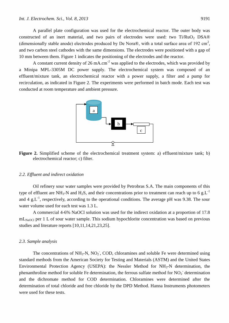
a Minipa MPL-3305M DC power supply. The electrochemical system was composed of an
effluent/mixture tank, an electrochemical reactor with a power supply, a filter and a pump for
recirculation, as indicated in Figure 2. The experiments were performed in batch mode. Each test was
conducted at room temperature and ambient pressure.
Figure 2. Simplified scheme of the electrochemical treatment system: a) effluent/mixture tank; b)
electrochemical reactor; c) filter.
2.2. Effluent and indirect oxidation
Oil refinery sour water samples were provided by Petrobras S.A. The main components of this
type of effluent are NH3-N and H2S, and their concentrations prior to treatment can reach up to 6 g.L-1
and 4 g.L-1
, respectively, according to the operational conditions. The average pH was 9.38. The sour
water volume used for each test was 1.3 L.
A commercial 4-6% NaOCl solution was used for the indirect oxidation at a proportion of 17.8
mLNaOCl per 1 L of sour water sample. This sodium hypochlorite concentration was based on previous
studies and literature reports [10,11,14,21,23,25].
2.3. Sample analysis
The concentrations of NH3-N, NO2-, COD, chloramines and soluble Fe were determined using
standard methods from the American Society for Testing and Materials (ASTM) and the United States
Environmental Protection Agency (USEPA): the Nessler Method for NH3-N determination, the
phenanthroline method for soluble Fe determination, the ferrous sulfate method for NO2- determination
and the dichromate method for COD determination. Chloramines were determined after the
determination of total chloride and free chloride by the DPD Method. Hanna Instruments photometers
were used for these tests.
a
b
c
Int. J. Electrochem. Sci., Vol. 8, 2013
9192
2.4. Current efficiencies and energy consumption
The average current efficiency (ACE) and energy consumption (EC) were determined using
Equations (12) and (13) after considering the removal of NH3-N [1,20]:
EC = (ΔEc x I x t)/(3600 x V) kWh. L-1
(12)
where t (s) is the time of the electrochemical treatment, ΔEc (V) is the average cell voltage, I
(A) is the electrochemical treatment current and V (L) is the sample volume;
%ACE = {3 x [(NH3-N)i – (NH3-N)f] x F x V}/(14 x I x t) (13)
where t (s) is the time of the electrochemical treatment, (NH3-N)i and (NH3-N)f are the initial
and final concentrations of NH3-N (g.L-1
), respectively, I (A) is the electrochemical treatment current,
F is the Faraday constant (96,485 C mol-1
), V (L) is the sample volume, 3 is the number of exchanged
electrons for the electrochemical oxidation of ammonia and 14 (g.mol-1
) is the molecular mass of
nitrogen.
3. RESULTS AND DISCUSSION
3.1. Electrochemical reactor
The parallel-plate reactor is well known for its efficiency [30]. In this work, a hydrodynamic
study was developed to demonstrate the suitability of this reactor design for the proposed
electrochemical treatment and to obtain the mass transfer coefficient (Kl) for the process. A typical
expected Kl value in industrial applications can range from 10-6
to 10-4
m.s-1
, depending on
manufacturing costs, maintenance and process efficiency [30].
In the case of the parallel-plate reactor design, a turbulent flow regime takes place, and the
mass transfer coefficient can be defined by Equation (14):
Kl = 0.023 Re0,8
Sc1/3
Di/de (14)
where:
Di is the diffusion coefficient of NH4+, and Di = 1.957 x 10
-9 m
2.s
-1, assuming the slowest ion-
controlling process, de is the hydraulic diameter, de = 9.41 x 10⁻³
m, Sc is the Schmidt number, Sc = µ
/ (ρ x Di), µ is the water viscosity, µ = 1 x 10⁻³
N.s.m-2
, ρ is the water density, ρ = 1000 kg.m-3
, Re is
the Reynolds number, Re = (de x ρ x ν) / µ, ν is the fluid velocity and ν = Q / A m.s-1
, Q is the fluid
output and Q = 8.5 x 10⁻⁵
m3.s
-1, A is the fluid passage hydraulic area and A = 4 x 10
-4 m
2.
According to Equation (14) and process data, Kl = 1.64 x 10⁻⁵
m.s-1
.

Int. J. Electrochem. Sci., Vol. 8, 2013
9193
In terms of industrial applications, this Kl is an acceptable value. Therefore, the reactor design
was suitable for the electrochemical treatment developed in this work.
3.2. Electrodes
When a current density of j = 26 mA.cm-2
was applied during preliminary tests, the potential
values at the anode and cathode remained constant during the entire electrochemical process. This
behavior indicated that the system was electrochemically stable.
The Ti/RuO2 DSA anodes did not exhibit any visible signs of surface damage, in agreement
with the results discussed in the literature. This type of electrode is known for its significant surface
and structural stability. According to Pourbaix [40], the potential achieved by the cathode during the
electrochemical process (-3 V to -4 V) and at a solution pH of 9.4 are conditions in which Fe is
thermodynamically immune to corrosion.
However, before the electrochemical treatment was initiated and while the current density was
zero, the potential value of the carbon steel electrode was approximately 0.4 V. Under these
conditions, corrosion processes are thermodynamically favorable for this material [40]. Several
minutes were required to allow adjustments of the system parameters, and this time was sufficient for
the corrosion processes to occur at the carbon steel electrode. The corrosion processes during system
shut-down were expected and were not expected to interfere with the electrochemical treatment
process. Additionally, a decrease in pH was observed during some tests, which was attributed to the
hydrolysis of chlorine, according to Equation (7) [4]. This phenomenon created thermodynamic
conditions in which carbon steel corrosion was possible. Through the optimization of the systems
parameters it is possible to soften the corrosion processes during the electrochemical treatment.
3.3. NH3-N removal
After the preliminary hydrodynamic study and electrodes tests, the electrochemical treatment
of the industrial sour water was performed. Three groups of tests were accomplished to verify the
response of the system according to the optimization of the use of indirect oxidant. The treatments
lasted for 7 hours.
Table 1. Average characteristics of oil refinery sour water
pH NH3-N
mg.L-1
NO2-
mg.L-1
COD
mg.L-1
Soluble Fe
mg.L-1
Chloramines
mg.L-1
9.38 2350 3400 5690 6200 8
As previously mentioned, a sample volume of 1.3 L of sour water was used for each
electrochemical treatment.
In Test 1, NaOCl was added once only at the beginning of the process. In Test 2, NaOCl was
added at the beginning and at two additional instances during the process at the same proportion of

Int. J. Electrochem. Sci., Vol. 8, 2013
9194
17.8 mLNaOCl per 1 L of sour water sample. In Test 3, NaOCl was added at the beginning and at one
additional instance during the process at the same proportion. The concentrations of NH3-N, NO2-,
COD, chloramines and soluble Fe and pH value were measured at specific time intervals. The H2S
content was not considered in this work because the treatment was performed with samples obtained
after this compound has been already removed.
The basic characteristics of the sour water effluent, not considering H2S, are indicated in Table
1, which report the average values. The variations in NH3-N content and in pH are shown in Figures 3
and 4, respectively.
0 1 2 3 4 5 6 7 8
0
200
400
600
800
1000
1200
1400
1600
1800
2000
2200
2400
2600
2800
3000
NH
3-N
(m
g.L
-1)
t (h)
Test 1
Test 2
Test 3
Figure 3. Variations in NH3-N content according to the NaOCl injection system. Test 1: NaOCl added
at the beginning of the process; Test 2: NaOCl added at the beginning and at two additional
occasions during the process; Test 3: NaOCl added at the beginning and once more during the
process. Intermediary NaOCl injections are indicated by the squares.
0 1 2 3 4 5 6 7 8
0
1
2
3
4
5
6
7
8
9
10
11
12
13
14
pH
t (h)
Test 1
Test 2
Test 3
Figure 4. Variations in pH according to the NaOCl injection system.
In Test 1, hypochlorite was added to the system at the beginning of the electrochemical
treatment (t=0), and the pH remained stable under these conditions. As shown in Figure 3, however,
the NH3-N content profile exhibited a significant initial decay that was followed by a positive
variation. According to Vitse et al. [12], Lima et al. [14], Li et al. [16], Bonnin [41], and Seed et al.
[42], the use of DSA anodes during the electrochemical removal of ammonia compounds leads to a
Int. J. Electrochem. Sci., Vol. 8, 2013
9195
final product that is free of nitrogen oxides. According to the same references, the final product is
primarily N2. However, depending on the conditions of the system, nitrate and nitrite are possible co-
products. Additionally, as shown in Equation (1), only the N2 formation pathway is irreversible, which
means that the NH3-N content variation in Figure 3 likely indicated the reversible nitrite and nitrate
formation reactions. Thus, the ammonia and ammonium ions were not completely transformed to N2.
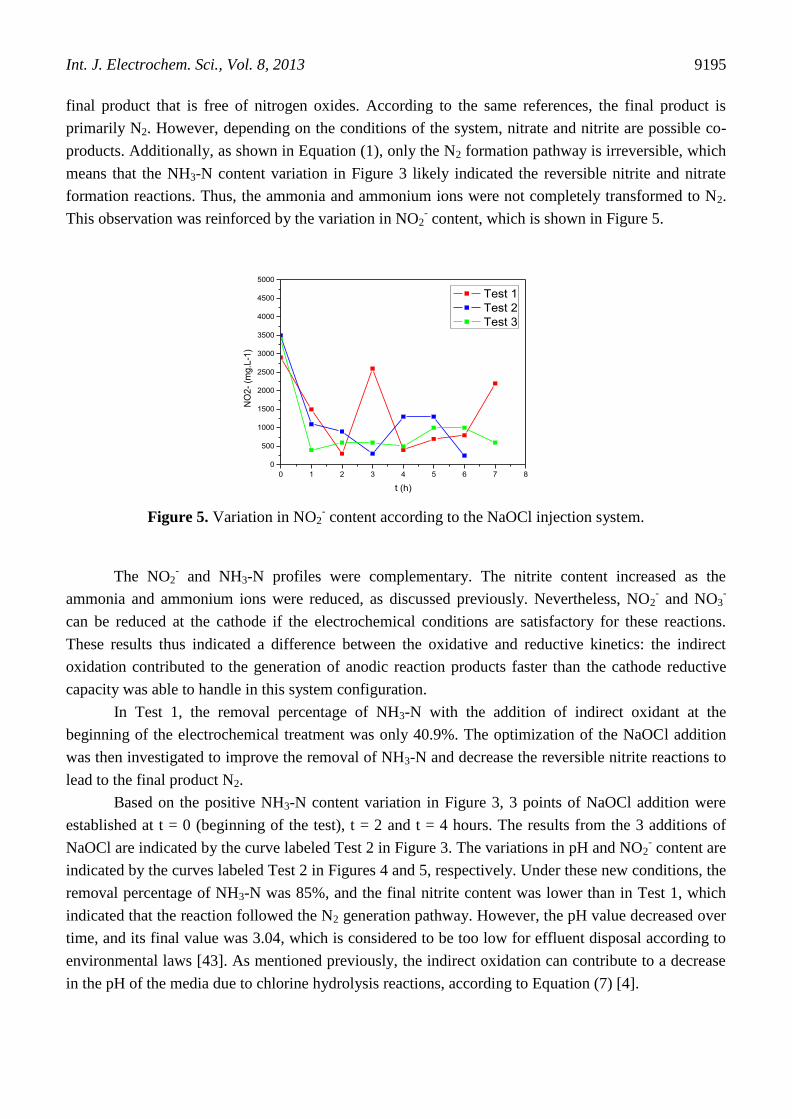
This observation was reinforced by the variation in NO2- content, which is shown in Figure 5.
0 1 2 3 4 5 6 7 8
0
500
1000
1500
2000
2500
3000
3500
4000
4500
5000
NO
2-
(mg
.L-1
)
t (h)
Test 1
Test 2
Test 3
Figure 5. Variation in NO2
- content according to the NaOCl injection system.
The NO2- and NH3-N profiles were complementary. The nitrite content increased as the
ammonia and ammonium ions were reduced, as discussed previously. Nevertheless, NO2- and NO3
-
can be reduced at the cathode if the electrochemical conditions are satisfactory for these reactions.
These results thus indicated a difference between the oxidative and reductive kinetics: the indirect
oxidation contributed to the generation of anodic reaction products faster than the cathode reductive
capacity was able to handle in this system configuration.
In Test 1, the removal percentage of NH3-N with the addition of indirect oxidant at the
beginning of the electrochemical treatment was only 40.9%. The optimization of the NaOCl addition
was then investigated to improve the removal of NH3-N and decrease the reversible nitrite reactions to
lead to the final product N2.
Based on the positive NH3-N content variation in Figure 3, 3 points of NaOCl addition were
established at t = 0 (beginning of the test), t = 2 and t = 4 hours. The results from the 3 additions of
NaOCl are indicated by the curve labeled Test 2 in Figure 3. The variations in pH and NO2- content are
indicated by the curves labeled Test 2 in Figures 4 and 5, respectively. Under these new conditions, the
removal percentage of NH3-N was 85%, and the final nitrite content was lower than in Test 1, which
indicated that the reaction followed the N2 generation pathway. However, the pH value decreased over
time, and its final value was 3.04, which is considered to be too low for effluent disposal according to
environmental laws [43]. As mentioned previously, the indirect oxidation can contribute to a decrease
in the pH of the media due to chlorine hydrolysis reactions, according to Equation (7) [4].
Int. J. Electrochem. Sci., Vol. 8, 2013
9196
Test 3 was then performed with one extra point of NaOCl injection in addition to the NaOCl
added initially. Thus, 2 points of NaOCl addition were established at in t = 0 (beginning of the test)
and t = 3 hours. The results from the 2 additions of NaOCl are indicated by the curve labeled Test 3 in
Figure 3. The variations in pH and NO2- content are indicated by the curves labeled Test 3 in Figures 4
and 5, respectively. Test 3 included the best operating conditions with regard to the pH value.
According to Figure 4, the pH profile for Test 3 was nearly constant, and the final value was 6.58,
which is considered to be adequate for effluent disposal according to environmental laws [43]. This
result also indicated that there existed an optimum value for the indirect oxidant in which the reaction
of hydrolysis of chlorine would not be predominant and pH would remain stable. The removal
percentage of NH3-N in Test 3 was 68.2%. This result was not as satisfactory as the removal from Test
2, however, the pH value was higher in Test 3 than in Test 2. The nitrite profile appeared to follow the
NH3-N profile, and the reactions also appeared to follow the N2 generation pathway.
In general, the removal of NH3-N increased by increasing the indirect oxidant content, as
discussed in the literature and demonstrated in this work. However, the pH was strongly affected by
the indirect oxidant content. Therefore, despite the promising results in Test 3, the electrochemical
system could be further optimized to achieve the best configuration for higher NH3-N removal.
Additionally, the generated nitrite could be separated and used, for example, as a corrosion inhibitor.
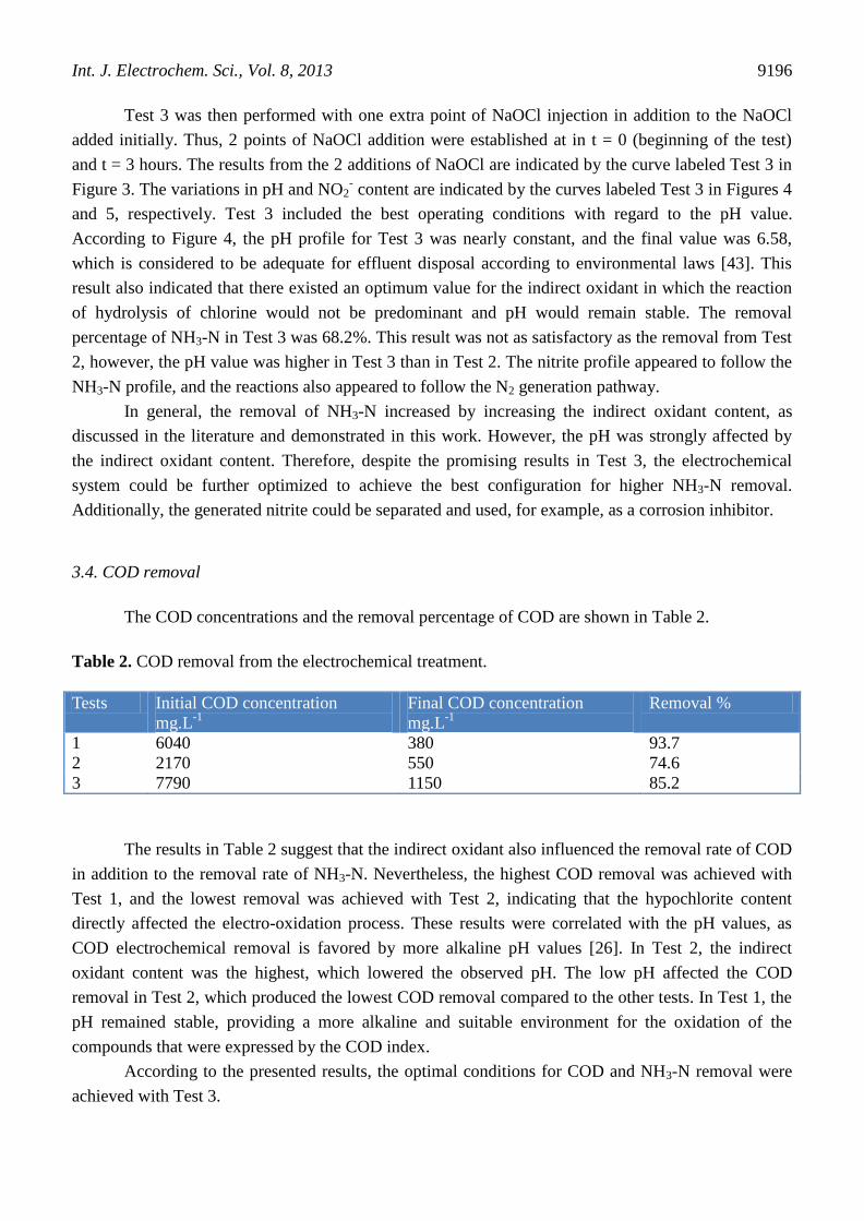
3.4. COD removal
The COD concentrations and the removal percentage of COD are shown in Table 2.
Table 2. COD removal from the electrochemical treatment.
Tests Initial COD concentration
mg.L-1
Final COD concentration
mg.L-1
Removal %
1 6040 380 93.7
2 2170 550 74.6
3 7790 1150 85.2
The results in Table 2 suggest that the indirect oxidant also influenced the removal rate of COD
in addition to the removal rate of NH3-N. Nevertheless, the highest COD removal was achieved with
Test 1, and the lowest removal was achieved with Test 2, indicating that the hypochlorite content
directly affected the electro-oxidation process. These results were correlated with the pH values, as
COD electrochemical removal is favored by more alkaline pH values [26]. In Test 2, the indirect
oxidant content was the highest, which lowered the observed pH. The low pH affected the COD
removal in Test 2, which produced the lowest COD removal compared to the other tests. In Test 1, the
pH remained stable, providing a more alkaline and suitable environment for the oxidation of the
compounds that were expressed by the COD index.
According to the presented results, the optimal conditions for COD and NH3-N removal were
achieved with Test 3.

Int. J. Electrochem. Sci., Vol. 8, 2013
9197
3.5. Soluble Fe and chloramines
The soluble Fe content provided information about the stability of the cathode material in the
sour water media. Although the initial thermodynamic conditions were favorable to Fe immunity
toward corrosion, corrosion was still possible due to variations in the pH [40]. The corrosion of Fe at
varying pH was indeed observed: in Test 1, the final soluble Fe content remained stable at
approximately 7000 mg.L-1
, while in Tests 2 and 3, it increased by approximately 20%.
Chloramines were also evaluated, as their formation depends mainly on pH, temperature and
the concentration ratios between active chlorine and ammonia [25,27]. Some authors have previously
reported that chloramines were highly unstable and that the final concentrations of chloramines were
zero [16,21,25,27]. The results obtained in this work are presented in Figure 6.
0 1 2 3 4 5 6 7 8
0
5
10
15
20
25
30
35
40
45
50
55
60
65
70
Ch
lora
min
es (
mg
.L-1
)
t (h)
Test 1
Test 2
Test 3
Figure 6. Chloramine content variation according to the NaOCl injection system.
According to Figure 6, the pH affected the chloramine generation during the tests. In Test 2 in
which the lowest pH value was achieved, the final chloramine concentration was lower than the initial
concentration, indicating a removal of 52.9%. In this case, the chloride in the solution was subjected to
hydrolysis according to Equation (7), and chloramines were more easily decomposed. In contrast, the
higher pH values in Tests 1 and 3 contributed to the generation of chloramines.
3.6. Average current efficiencies and energy consumption
The average current efficiencies (ACE) and the energy consumption (EC) were calculated for
each test according to Equations (12) and (13) considering the NH3-N removal data. The results are
shown in Table 3. In Test 2, the test time was different because the experiment was finished early due
to the low pH value, as indicated in Figure 4. According to Chen et al. [1], an increase in the indirect
oxidant content promoted an increase in the ACE. This was demonstrated by the Test 2 results, which
showed the highest average current efficiency. In addition, according to Table 3, the energy
consumption decreased with increased indirect oxidant concentrations, which would indicate lower
operating costs as well.

Int. J. Electrochem. Sci., Vol. 8, 2013
9198
Table 3. ACE and CE during the electrochemical treatment of oil refinery sour water.
Tests [(NH3-N)i - (NH3-N)f]
g.L-1
V
(L)
ΔEc
(V)
I
(A)
t
(s)
%ACE EC
kWh.L-1
1 0.9 1.3 8.40 5 25200 19 226.15
2 1.7 1.3 8.48 5 21600 42 195.69
3 1.5 1.3 7.77 5 25200 32 209.19
Considering the composition of the sour water used in this study, which contained elevated
NH3-N and COD concentrations in addition to other compounds, the obtained current efficiencies were
not considered too low when compared to the literature data. Additionally, the energy demand was not
too high, although it could be considered elevated when compared to biological processes. However,
the electrochemical treatment process presents more reliable results compared to biological processes
[1,20,44].
The electrochemical treatment proposed in this study presented promising NH3-N and COD
removal efficiencies. The configuration of the electrochemical system could be further optimized to
achieve a lower EC, a higher ACE and a greater removal percentage of NH3-N to guarantee that the
final solution parameters are in accordance with the limits established by environmental laws for
effluent disposal [43] and to guarantee that the energy consumption is satisfactory for industrial
applications. Although the energy demand was high, the electrochemical treatment is still an attractive
and environmentally friendly process that occupies less area and is typically performed under ambient
temperature and pressure, which makes the process easier to operate, control and maintain. The
electrochemical system can be further optimized both in terms of current density and energy
consumption [7-9].
4. CONCLUSIONS
- The parallel-plate configuration is a suitable design for the electrochemical reactor. The
hydrodynamic parameters indicate the applicability of this design to further industrial scale.
- There is a NaOCl concentration limit in which the indirect oxidation remains active
without lowering the pH of the media. In addition, the electrochemical treatment with the indirect
oxidation is an interesting alternative process for NH3-N and COD removal.
- The best system configuration for the electrochemical treatment for NH3-N and COD
removal in this work was achieved in Test 3 with the use of two points of addition of the indirect
oxidant NaOCl. The pH remained stable and favored the removal of COD. Additional studies are
required to improve the removal percentage of NH3-N and COD to guarantee that the final solution
parameters are in accordance with the limits established by environmental laws for effluent disposal.
- Additional studies could be performed to decrease the energy demand and to improve
the current efficiency.
Int. J. Electrochem. Sci., Vol. 8, 2013
9199
References
1. J. Chen, H. Shi and J. Lu, J. Appl. Electrochem. 37 (2007) 1137.
2. X. Ma, R. Wang, W. Guo, H. Yang, Z. Liang and C. Fan, Int. J. Electrochem. Sci., 7 (2012) 6012.
3. H. Xu, A. Li, L. Feng, X. Cheng and S. Ding, Int. J. Electrochem. Sci., 7 (2012) 7516.
4. M. Panizza, C. Bocca and G. Cerisola, Water Res., 34 (2000) 2601.
5. J. L. N. Xavier, E. Ortega, J. Z. Ferreira, A. M. Bernardes and V. Pérez-Herranz, Int. J.
Electrochem. Sci., 6 (2011) 622.
6. H. A. Moreno-Casillas, D. L. Cocke, J.A.G. Gomes, P. Morkovsky, J.R. Parga and E. Peterson,
Sep. Purif. Technol., 56 (2007) 204.
7. L. C. Candido and J. A. C Ponciano Gomes, Mater. Chem. Phys., 129 (2011) 1146.
8. Y. Yavuz, A. S. Koparal and Ü. B. Ögütveren, Desalination, 258 (2010) 201.
9. Z. Liang, S.Li, W.Guo and C. Fan, Chinese J. Chem. Eng. 19 (2011) 570.
10. K. Kim, Y. Kim, I. Kim, G. Park and E. Lee, Electrochim. Acta, 50 (2005) 4356.
11. K. Kim, Y. Kim, I. Kim, G. Park and E. Lee, Water Res., 40, (2006) 1431.
12. F. Vitse, M. Cooper and G. G. Botte, J. Power Sources, 142 (2005) 18.
13. L. Marincic and F. B. Leitz, J. Appl. Electrochem., 8 (1978) 333.
14. R. M. G. Lima, G. R. S. Wildhagen, J. W. S. D. Cunha and J. C. Afonso, J. Hazard. Mater., 161
(2009) 1560.
15. A. C. A. De Vooys, M. T. M. Koper, R. A. Van Santen and J. R. A. Van Veen, J. Electroanal.
Chem., 506 (2001) 127.
16. M. Li, C. Feng, Z. Zhang, S. Yang and N. Sugiura, Bioresource Technol., 101 (2010) 6553.
17. A. Kapalka, A. Cally, S. Neodo, C. Comninellis, M. Wächter and K. M. Udert, Electrochem.
Commun., 12 (2010) 18.
18. H. Gerischer and A. Mauerer, A., J. Electroanal. Chem., 25 (1970) 421.
19. A. J. Bard, R. Parsons and J. Jordan, Standard Potentials in Aqueous Solution, Marcel Dekker Inc.,
New York (1985).
20. J.H.B. Rocha, M.M.S. Gomes, N.S. Fernandes, D.R. da Silva and C.A. Martínez-Huitle, Fuel
Process. Technol., 96 (2012) 80.
21. L. Li and Y. Liu, J. Hazard.Mater., 161 (2009) 1010.
22. E. P. Bonnin, E. J. Biddinger and G. G. Botte, J. Power Sources, 182 (2008) 284.
23. L. Szpyrkowicz, S. N. Kaul, R. N. Neti and S. Satyanarayan, Water Res., 39 (2005) 1601.
24. O. Scialdone, S. Randazzo, A. Galia and G. Silvestri, Water Res., 43 (2009) 2260.
25. Y. Y. Gendel and O. Lahav, Electrochim. Acta, 63 (2012) 209.
26. K-H. Yeon, J-H. Song, J. Shim, S-H. Moon, Y-U. Jeong and H-Y. Joo, Desalination, 202 (2007)
400.
27. A. Kapalka, A. Katsaounis, N. Michels, A. Leonidova, S. Souentie, C. Comninellis and K. M.
Udert, Electrochem. Commun., 12 (2010) 1203.
28. J. H. Cho, J. E. Lee and C. S. Ra, J. Hazard. Mater., 180 (2010) 535.
29. S. Sundarapandiyan, R. Chandrasekar, B. Ramanaiah, S. Krishnan and P. Saravanan, J. Hazard.
Mater., 180 (2010) 197.
30. D. Pletcher and F.C. Walsh, Industrial Electrochemistry, Chapman and Hall, London (1990).
31. Y. Liu, L. Li and R. Goel, J. Hazard. Mater., 167 (2009) 959.
32. J. F. E Gootzen, A. H. Wonders, W. Visscher, R. A. Van Santen and J. R. A. Van Veen, Electrochim. Acta, 43 (1998) 1851.
33. M. Della Monica, A. Agostiano and A. Ceglie, J. Appl. Electrochem., 10 (1980) 527.
34. S. Wasmus, E. J. Vasini, M. Krausa, H. T. Mishima and W. Vielstich, Electrochim. Acta, 39 (1994)
23.
35. K. Sasaki and Y. Hisatomi, J. Electrochem. Soc., 117 (1970) 758.
36. C. Feng, N. Sugiura, S. Shimada and T. Maekawa, J. Hazard. Mater. B, 103 (2003) 65.

Int. J. Electrochem. Sci., Vol. 8, 2013
9200
37. K. Endo, Y. Katayama and T. Miura, Electrochim. Acta, 49 (2004) 1635.
38. K. Yao and Y. F. Cheng, Int. J. Hydrogen Energ., 33 (2008) 6681.
39. K. Yao and Y. F. Cheng, Mater. Chem. Phys., 108 (2008) 247.
40. M. Pourbaix, Atlas of Electrochemical Equilibria in Aqueous Solutions, NACE, CEBELCOR,
Houston (1974).
41. E. P. Bonnin, Electrolysis of Ammonia Effluents: a Remediation Process with Co-Generation of
Hydrogen, M.Sc. dissertation, Ohio University, Ohio (2006).
42. L. P. Seed, D. D. Yetman, S. W. Key and G. S. Shelp, A Novel Ion-exchange/Electrochemical
Technology for the treatment of Ammonia in Wastewater, Enpar Technologies Inc., Canada (2003).
43. Anonymous, CONAMA Resolution nº 357. Published at D.O.U. n˚ 66 in 2008, Section 1, Brazil
(2008).
44. A. M. Z. Ramalho, C. A. Martinez-Huitle, D. R. da Silva, Fuel, 89 (2010) 531.
© 2013 by ESG (www.electrochemsci.org)