Electrochemical Synthesis of o-anisidine - o aminophenol ...
12
Chemistry and Materials Research www.iiste.org ISSN 2224- 3224 (Print) ISSN 2225- 0956 (Online) Vol.3 No.10, 2013 1 Electrochemical Synthesis of o-anisidine - o- aminophenol Copolymers Mutlaq Shediad Al-jahdali 1 Abdel Aziz Qasem Mohammad Jbarah 2* Amneh Al-Ameen Mohammad Ahmed 3 1. Chemistry Department, Faculty of Science, King Abdulaziz University, PO box 80200, Jeddah 21589, Saudi Arabia 2. Chemistry Department, Faculty of Arts and Science, Northern Borders University, PO box 1321, ArAr 91431, Rafha campus, Saudi Arabia 3. Pharmacy Department, Faculty of Pharmacy, Northern Borders University, PO box 1321, ArAr 91431, Rafha campus, Saudi Arabia * E-mail of the corresponding author: [email protected] Abstract Electroactive conducting copolymers of o-anisidine and o-aminophenol molecules were pre-pared in aqueous solution by electrode potential cycling. Copolymerization was carried out at constant feed concentration of o- anisidine (30 mM) and different feed concentration of o-aminophenol on a gold electrode. Three different feed concentrations of o-aminophenol were used to prepare three different copolymers. The obtained copolymers were characterized with cyclic voltammetry. Both homopolymers and copolymers were obtained by cycling the potential between -0.20 V and different upper potential limits. The copolymers formed with different feed concentrations of o-aminophenol exhibited different cyclic voltammetric behaviors. In some cases using different cycling range of polymerization leads to different cyclic voltammetric behaviors of the obtained copolymers. Keywords: cyclic voltammetry, o-anisidine, o-aminophenol, copolymers 1. Introduction Conducting polymers attract great interest as promising candidates for various applications such as electrocatalysts, electrochromic devices, solar cells and rechargeable batteries (Sherman et al. 1994, Holze 2001). One of the most interesting conducting polymers is polyaniline and it has occupied the prime position because of its high conductivity, good redox reversibility, swift change of color with potential and good environmental stability ( Manisankar et al. 2005). Several researches are made to improve the properties of polyaniline. These improvements can be reached either via the polymerization of substituted monomers and post treatment or copolymerization of aniline with other monomers (Holze 2001). Copolymerization of two different monomers that bear different functional groups leads to modified copolymers that possessing interesting properties. The advantage of copolymerization is the possible homogeneity of the resulting material, the properties of which can be regulated by adjusting the ratio of the concentrations of the monomers in the feed. A self-doped polyaniline was obtained by copolymerization of aniline with some carboxyl- and sulfonyl-substituted derivatives (Karyakin et al.1994 and Karyakin et al. 1996). An electrochemical copolymerization of aniline with o/m-toluidines was reported (Wei et al. 1990). Aniline copolymerization with o-aminobenzonitrile yielded copolymers bearing cyanogroups. The electrochromic properties of these copolymers are different from those of polyaniline (Sato et al. 1994). Accelerations of the rate of electropolymerization of aniline with p-phenylenediamine and retardation with m-phenylenediamine have been reported ( Yang & Wen 1994, Tang et al. 1995, Si et al. 1995). The aniline derivative, o-aminophenol (OAP), has attracted much attention in the last few years. OAP can be polymerized by suitable oxidation either chemically or electrochemically (Kunimura et al. 1988, Barbero et al. 1989, Zhang et al. 1994, Pace & Kim 1988). The electropolymerization of OAP has been investigated with electrochemical techniques (Tucceri 2004), ellipsometry (Barbero et al. 1987), in situ Raman spectroscopy (Salavagione et al. 2005) and impedance measurements (Barbero et al. 1995). Poly(o-aminophenol), (POAP), has been assigned the structure of a ladder polymer based on repeating phenoxazine units. A preliminary study of Mu (2004) on the copolymerization of aniline (0.2 M) and OAP demonstrated that a small addition of OAP (0.01 M) to the aniline solution could result in copolymer formation on a platinum electrode. However, OAP concentration greater than 0.01 M in the feed strongly inhibited the growth of the copolymer and the author suggested that for higher OAP concentration in the feed the copolymer could not grow. Moreover, the upper potential limit for the homopolymer synthesis was rather high which could result in the overoxidation of aniline and partial degradation of polyaniline and is also not suitable for POAP synthesis as is well known in the literature (Ortega 2000, Zhang et al. 1994). As in polyaniline, the electro-oxidation of poly(o-anisidine) in aqueous acidic media yields a film with desirable
Transcript of Electrochemical Synthesis of o-anisidine - o aminophenol ...
Chemistry and Materials Research www.iiste.org
ISSN 2224- 3224 (Print) ISSN 2225- 0956 (Online)
Vol.3 No.10, 2013
1
Electrochemical Synthesis of o-anisidine - o-
aminophenol Copolymers
Mutlaq Shediad Al-jahdali1 Abdel Aziz Qasem Mohammad Jbarah
2*
Amneh Al-Ameen Mohammad Ahmed3
1. Chemistry Department, Faculty of Science, King Abdulaziz University, PO box 80200, Jeddah 21589,
Saudi Arabia
2. Chemistry Department, Faculty of Arts and Science, Northern Borders University, PO box 1321,
ArAr 91431 , Rafha campus, Saudi Arabia
3. Pharmacy Department, Faculty of Pharmacy, Northern Borders University, PO box 1321, ArAr 91431 ,
Rafha campus, Saudi Arabia
* E-mail of the corresponding author: [email protected]
Abstract
Electroactive conducting copolymers of o-anisidine and o-aminophenol molecules were pre- pared in aqueous
solution by electrode potential cycling. Copolymerization was carried out at constant feed concentration of o-
anisidine (30 mM) and different feed concentration of o- aminophenol on a gold electrode. Three different feed
concentrations of o-aminophenol were used to prepare three different copolymers. The obtained copolymers
were characterized with cyclic voltammetry. Both homopolymers and copolymers were obtained by cycling the
potential between -0.20 V and different upper potential limits. The copolymers formed with different feed
concentrations of o-aminophenol exhibited different cyclic voltammetric behav iors. In some cases using
different cycling range of polymerization leads to different cyclic voltammetric behaviors of the obtained
copolymers.
Keywords: cyclic voltammetry , o-anisidine, o-aminophenol, copolymers
1. Introduction
Conducting polymers attract great interest as promising candidates for various applications such
as electrocatalysts, electrochromic devices, solar cells and rechargeable batteries (Sherman et al. 1994,
Holze 2001). One of the most interesting conducting polymers is polyaniline and it has occupied
the prime position because of its high conductivity, good redox reversibility, swift change of color
with potential and good environmental stability ( Manisankar et al. 2005). Several researches are made to
improve the properties of polyaniline. These improvements can be reached either via the polymerization
of substituted monomers and post treatment or copolymerization of aniline with other monomers (Holze 2001 ).
Copolymerization of two different monomers that bear different functional groups leads to modified copolymers
that possessing interesting properties. The advantage of copolymeriza tion is the possible homogeneity of the
resulting material, the properties of which can be regulated by adjusting the ratio of the concentrations of the
monomers in the feed. A self-doped polyaniline was obtained by copolymerization of aniline with some
carboxyl- and sulfonyl- substituted derivatives (Karyakin et al. 1994 and Karyakin et al. 1996). An
electrochemical copolymerization of aniline with o/m-toluidines was reported (Wei et al. 1990). Aniline
copolymerization with o-aminobenzonitrile yielded copolymers bearing cyanogroups. The electrochromic
properties of these copolymers are different from those of polyaniline (Sato et al. 1994). Accelerations of the rate
of electropolymerization of aniline with p-phenylenediamine and retardation with m-phenylenediamine have
been reported ( Yang & Wen 1994, Tang et al. 1995, Si et al. 1995).
The aniline derivative, o-aminophenol (OAP), has attracted much attention in the last few years. OAP can be
polymerized by suitable oxidation either chemically or electrochemically (Kunimura et al. 1988, Barbero et al.
1989, Zhang et al. 1994, Pace & Kim 1988 ). The electropolymerization of OAP has been investigated with
electrochemical techniques (Tucceri 2004), ellipsometry (Barbero et al. 1987), in situ Raman
spectroscopy (Salavagione et al. 2005) and impedance measurements (Barbero et al. 1995). Poly(o-aminophenol),
(POAP), has been assigned the structure of a ladder polymer based on repeating phenoxazine units. A
preliminary study of Mu (2004) on the copolymerization of aniline (0.2 M) and OAP demonstrated that a small
addition of OAP (0.01 M) to the aniline solution could result in copolymer formation on a platinum electrode.
However, OAP concentration greater than 0.01 M in the feed strongly inhibited the growth of the copolymer and
the author suggested that for higher OAP concentration in the feed the copolymer could not grow. Moreover, the
upper potential limit for the homopolymer synthesis was rather high which could result in the overoxidation of
aniline and partial degradation of polyaniline and is also not suitable for POAP synthesis as is well known in
the literature (Ortega 2000, Zhang et al. 1994 ).
As in polyaniline, the electro-oxidation of poly(o-anisidine) in aqueous acidic media yields a film with desirable
Chemistry and Materials Research www.iiste.org
ISSN 2224- 3224 (Print) ISSN 2225- 0956 (Online)
Vol.3 No.10, 2013
2
properties ( Mottoso & Bulhoes 1992 ). According to our knowledge copolymerization of OAN with OAP are not
investigated till now. In the present work we report the results of electrochemical copolymerization of the o-
anisidine (OAN) and OAP .
2. Experimental
All chemicals were of analytical grade. OAN (Aldrich) was distilled under vacuum and stored under nitrogen in
a refrigerator. OAP (Fluka purum) was used as received. 18 MW water (Seralpur pro 90C) was used for solution
preparation. All solutions were prepared with 0.5 M sulfuric acid (Merck) supporting electrolyte.
Thin films of poly (o-anisidine), poly (o-aminophenol) and poly(o-anisidine co o-aminophenol) were synthesized
electrochemically under potentiodynamic conditions at a scan rate of 50 mV/s. A three-electrode geometry was
employed with gold disc as working electrode and platinum wire as counter electrode and a saturated calomel
reference electrode. The surface area of the working electrode was approximately electrode0.1 cm2. All
potentials quoted in this work are referred to the saturated calomel electrode. Electrochemical experiments
were performed at room temperature (20 ˚C) with nitrogen purged solutions. Cyclic voltammetry was performed
with a computerized SP50 potentiostat (from Bio Logic Science Instruments, France). All solutions were freshly
prepared and purged with nitrogen (99.999%).
3. Results and Discussion
3.1 Electrochemical homopolymerization of OAP
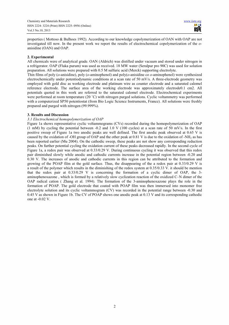
Figure 1a shows representative cyclic voltammograms (CVs) recorded during the homopolymerization of OAP
(1 mM) by cycling the potential between -0.2 and 1.0 V (100 cycles) at a scan rate of 50 mV/s. In the first
positive sweep of Figure 1a two anodic peaks are well defined. The first anodic peak observed at 0.65 V is
caused by the oxidation of -OH group of OAP and the other peak at 0.81 V is due to the oxidation of -NH2 as has
been reported earlier (Mu 2004). On the cathodic sweep, these peaks are not show any corresponding reduction
peaks. On further potential cycling the oxidation current of these peaks decreased rapidly. In the second cycle of
Figure 1a, a redox pair was observed at 0.33/0.29 V. During continuous cycling it was observed that this redox
pair diminished slowly while anodic and cathodic currents increase in the potential region between -0.20 and
0.30 V. The increases of anodic and cathodic currents in this region can be attributed to the formation and
growing of the POAP film at the gold surface. Thus, the disappearing of the a redox pair at 0.33/0.29 V is
a result of the polymer which results in the diminishing of the redox system at 0.35/0.33 V. it should be mention
that the redox pair at 0.33/0.29 V is concerning the formation of a cyclic dimer of OAP, the 3-
aminophenoxazone , which is formed by a relatively slow cyclization reaction of the oxidized C–N dimer of the
OAP radical cation ( Zhang et al. 1994). The formation of the 3-aminophenoxazone plays the role in the
formation of POAP. The gold electrode that coated with POAP film was then immersed into monomer free
electrolyte solution and its cyclic voltammogram (CV) was recorded in the potential range between -0.30 and
0.45 V as shown in Figure 1b. The CV of POAP shows one anodic peak at 0.13 V and its corresponding cathodic
one at -0.02 V.
Chemistry and Materials Research www.iiste.org
ISSN 2224- 3224 (Print) ISSN 2225- 0956 (Online)
Vol.3 No.10, 2013
3
-0.2 0.0 0.2 0.4
-0.004
-0.002
0.000
0.002
(b )
I /m
A
ESCE
0.0 0.5 1.0
-0.005
0.000
0.005
0.010
cycle number 3cycle number 2cycle number 1(a )
I /m
A
ESCE
Figure 1. The cyclic voltammograms for (a) electrolysis of the solution containing 1 mM OAP in 0.5 M
H2SO4 by cycling the potential between -0.20 and 0.10 V, (b) POAP in monomer free electrolyte
solution at a scan rate of 50 mV/s
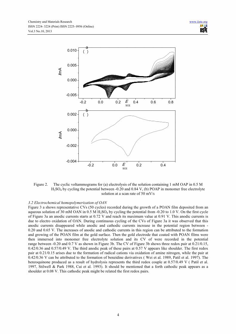
Shah & Holze (2006) reported that the POAP could not be deposited at gold surface from a solution of 1 mM
OAP in 0.5 M H2SO4 by using the upper value of cycling potential higher than 0.84 V. They concluded that the
POAP degrades at high anodic potentials. According to our results this is not correct. Actually,
the electrochemical behavior of the POAP in monomer free electrolyte varies according to the used
deposition condition. To show that, we record a second CVs (100 cycles) for the homopolymerization of OAP (1
mM) by cycling the potential between -0.2 and 0.84 V at a scan rate of 50 mV/s which are displayed in Figure
2a. It should be noted that the only difference between the first experiment (Figure 1a) and the second
one (Figure 2a) is the upper value of the cycling potential. It is clear that the CVs of Figure 2a different from that
of Figure 1a. This difference appears in the potential range from -0.20 to 0.30 V of the CVs. The obtained POAP
modified electrode from the second experiment was immersed into monomer free electrolyte solution and its CV
was recorded in the potential range between -0.20 and 0.45 V as depicted in Figure 2b. The CV (Figure 2b) of
POAP shows one anodic peak at 0.14 V and its corresponding cathodic one at 0.10 V. By comparing the CV of
Figure 1b with that of Figure 2b, one can note that the potential gab difference between the oxidation
potential and its corresponding reduction one of the POAP increases in the case of Figure 1b. Also the value of
anodic and cathodic peaks currents of the CV of Figure 1b are higher than those of the CV of Figure 2b.
Chemistry and Materials Research www.iiste.org
ISSN 2224- 3224 (Print) ISSN 2225- 0956 (Online)
Vol.3 No.10, 2013
4
-0.2 0.0 0.2 0.4
-0.004
-0.002
0.000
0.002 (b )
I /m
A
ESCE
-0.2 0.0 0.2 0.4 0.6 0.8
-0.005
0.000
0.005
0.010 (a )
I /m
A
ESCE
Figure 2. The cyclic voltammograms for (a) electrolysis of the solution containing 1 mM OAP in 0.5 M
H2SO4 by cycling the potential between -0.20 and 0.84 V, (b) POAP in monomer free electrolyte
solution at a scan rate of 50 mV/s
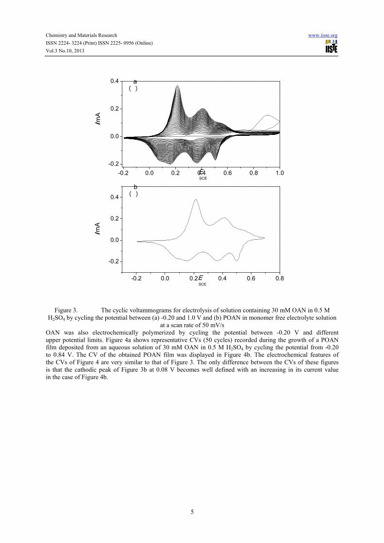
3.2 Electrochemical homopolymerization of OAN
Figure 3 a shows representative CVs (50 cycles) recorded during the growth of a POAN film deposited from an
aqueous solution of 30 mM OAN in 0.5 M H2SO4 by cycling the potential from -0.20 to 1.0 V. On the first cycle
of Figure 3a an anodic currents starts at 0.72 V and reach its maximum value at 0.91 V. This anodic currents is
due to electro oxidation of OAN. During continuous cycling of the CVs of Figure 3a it was observed that this
anodic currents disappeared while anodic and cathodic currents increase in the potential region between -
0.20 and 0.65 V. The increases of anodic and cathodic currents in this region can be attributed to the formation
and growing of the POAN film at the gold surface. Then the gold electrode that coated with POAN films were
then immersed into monomer free electrolyte solution and its CV of were recorded in the potential
range between -0.20 and 0.7 V as shown in Figure 3b. The CV of Figure 3b shows three redox pair at 0.21/0.15,
0.42/0.36 and 0.57/0.49 V. The third anodic peak of these pairs at 0.57 V appears like shoulder. The first redox
pair at 0.21/0.15 arises due to the formation of radical cations via oxidation of amine nitrogen, while the pair at
0.42/0.36 V can be attributed to the formation of benzidine derivatives ( Wei et al. 1989, Patil et al. 1997). The
benzoquinone produced as a result of hydrolysis represents the third redox couple at 0.57/0.49 V ( Patil et al.
1997, Stilwell & Park 1988, Cui et al. 1993). It should be mentioned that a forth cathodic peak appears as a
shoulder at 0.08 V. This cathodic peak might be related the first redox pairs.
Chemistry and Materials Research www.iiste.org
ISSN 2224- 3224 (Print) ISSN 2225- 0956 (Online)
Vol.3 No.10, 2013
5
-0.2 0.0 0.2 0.4 0.6 0.8
-0.2
0.0
0.2
0.4 (b )
I /m
A
ESCE
-0.2 0.0 0.2 0.4 0.6 0.8 1.0
-0.2
0.0
0.2
0.4
(a )
I /m
A
ESCE
Figure 3. The cyclic voltammograms for electrolysis of solution containing 30 mM OAN in 0.5 M
H2SO4 by cycling the potential between (a) -0.20 and 1.0 V and (b) POAN in monomer free electrolyte solution
at a scan rate of 50 mV/s
OAN was also electrochemically polymerized by cycling the potential between -0.20 V and different
upper potential limits. Figure 4a shows representative CVs (50 cycles) recorded during the growth of a POAN
film deposited from an aqueous solution of 30 mM OAN in 0.5 M H2SO4 by cycling the potential from -0.20
to 0.84 V. The CV of the obtained POAN film was displayed in Figure 4b. The electrochemical features of
the CVs of Figure 4 are very similar to that of Figure 3. The only difference between the CVs of these figures
is that the cathodic peak of Figure 3b at 0.08 V becomes well defined with an increasing in its current value
in the case of Figure 4b.
Chemistry and Materials Research www.iiste.org
ISSN 2224- 3224 (Print) ISSN 2225- 0956 (Online)
Vol.3 No.10, 2013
6
-0.2 0.0 0.2 0.4 0.6
-0.2
0.0
0.2
0.4 (b )
I /m
A
ESCE
-0.2 0.0 0.2 0.4 0.6 0.8
-0.2
0.0
0.2
0.4
(a )
I /m
A
ESCE
Figure 4. The cyclic voltammograms for electrolysis of solution containing 30 mM OAN in 0.5 M H2SO4 by
cycling the potential between (a) -0.20 and 0.84 V and (b) POAN in monomer free electrolyte
solution at a scan rate of 50 mV/s
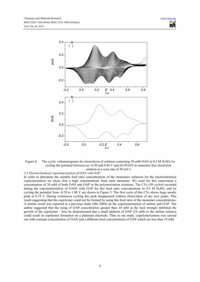
3.3 Electrochemical copolymerization of OAN with OAP
In order to determine the suitable feed ratio concentrations of the monomers solutions for the electrochemical
coplymerization we chose first a high concentrations from each monomer. We used for this experiment a
concentration of 30 mM of both OAN and OAP in the polymerization solutions. The CVs (50 cycles) recorded
during the copolymerization of OANI with OAP for this feed ratio concentrations in 0.5 M H2SO4 and by
cycling the potential from -0.20 to 1.00 V are shown in Figure 5. The first cycle of this CVs shows huge anodic
peak at 0.74 V. During continuous cycling this peak disappeared without observation of any new peaks. This
result suggesting that the copolymer could not be formed by using this feed ratio of the monomer concentrations.
A similar result was reported in a previous study (Mu 2004) on the copolymerization of aniline and OAP. The
author suggested that the using of OAP concentration greater than 10 mM in the feed strongly inhibited the
growth of the copolymer . Also he demonstrated that a small addition of OAP (10 mM) to the aniline solution
could result in copolymer formation on a platinum electrode. Thus in our study, copolymerization was carried
out with constant concentration of OAN and a different feed concentrations of OAP which are less than 10 mM.
Chemistry and Materials Research www.iiste.org
ISSN 2224- 3224 (Print) ISSN 2225- 0956 (Online)
Vol.3 No.10, 2013
7
0.0 0.5 1.0
0.0
0.1
0.2
I /m
A
ESCE
Figure 5. The cyclic voltammograms (50 cycle) for the solution of 30 mM OAN and 30 mM OAP in 0.5 M
H2SO4 by cycling the potential between -0.20 and 1.00 V at 50 mV/s
The copolymerization condition that used in our study are listed in Table 1 together with the copolymers labels.
Like the homopolymerization of OAP and OAN, electrolysis of mixed solutions containing both OAP and OAN
was carried out by cycling the potential between - 0.20 V and different upper potential limits.
Table 1. Monomers concentration, cycling range and number of cycles that used during electrochemical
preparation of each case of the copolymers.
Copolymer
lable
Cycling range
(mV)
Concentration of OAN
(mM)
Concentration
of OAM (mM)
Number of
cycles
A1 -200 - 840 30 1 50
B1 -200 - 840 30 3 50
C1 -200 - 840 30 5 50
A2 -200 - 1000 30 1 50
B2 -200 - 1000 30 3 50
C2 -200 - 1000 30 5 50
CVs recorded during the potentiodynamic copolymerization of OAN with OAP for system A1 are shown
in Figure 6a. In the first cycle of Figure 6a there are one anodic peak at 0.69 V and increasing in current between
0.69 V and 0.84 V. The anodic peak at 0.69 V can be assigned to the oxidation of the hydroxyl group of OAP.
The observed current between 0.69 V and 0.84 V is caused by the oxidation of amino groups from both
monomers. Actually the the oxidation of amino groups from both monomers occurs at electrode potential more
than 0.84 V as indicated from Figure 6d. In the cathodic scan of first cycle of Figure 6a there are two cathodic
peaks. From cycle number 10 to cycle number 50 the CVs of Figure 6a show well defined three anodic peaks
and four cathodic ones. These anodic and cathodic peaks are clearly indicated the deposition of the copolymer.
The behaviour of CVs of system A2 (Figure 6d) are similar to that of system A1 with limited differences. The
first difference is the observation of the anodic peak in the first cycle of system A2 at 0.88 V. This anodic peak
is not observed for system A1 because of using upper potential lower than 0.88 V. The second difference is that
the overall anodic and cathidc current in the CVs of system A2 are higher than that of system A1. This difference
also can be attributed to the difference in the upper potential limits that used in each case.
The first cycle behaviour of the CVs of the systems B1 (Figure 6b) and B2 (Figure 6e) are very similar to that of
systems A1 (Figure 6a) and A2 (Figure 6d), respectively. The behaviour of the subsequent cycles (from cycle
number 2 to cycle number 50) of the CVs of the systems B1 and B2 are different from that of systems A1 and
A2. In the CVs of systems B1 and B2 the anodic peaks position shifts to higher potential upon cycling. This
behaviour is not observed in the CVs of systems A1 and A2. The overall anodic and cathodic peak currents
of the systems B1 and B2 are lower than that of systems A1 and A2. These differences suggests the copolymers
formed in the case of systems A1 and A2 are different from that for systems B1and B2.
The CVs of the systems C1 and C2 are displayed in Figure 6c and 6f. The first cycle of these systems are similar
to that of other systems that discussed previously. The second cycle of the CVs of system C1 shows four anodic
peaks while it shows only three anodic peaks in the case of system C2. This results suggest that the oligomers
forms in the case of system C1 are different from that of system C2. This conclusion is based on that the second
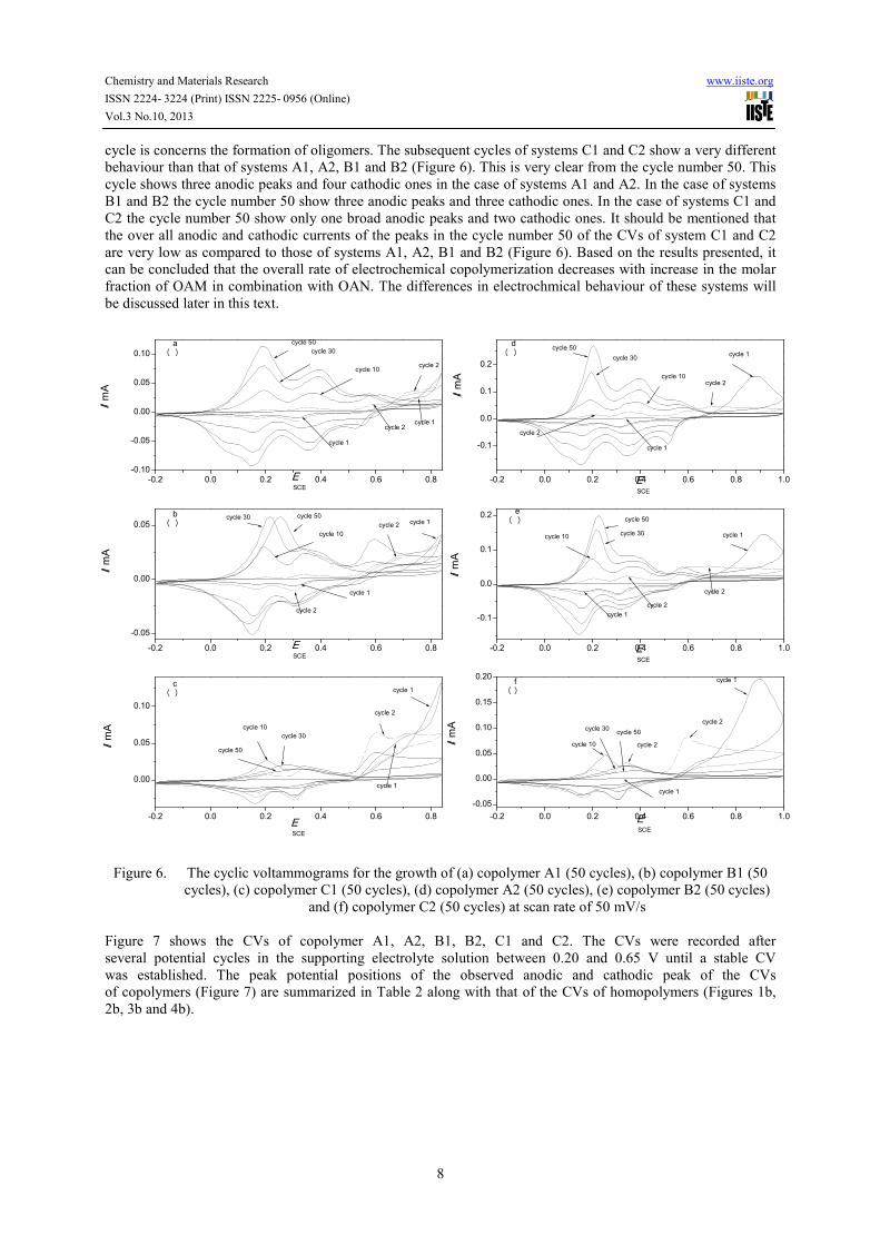
Chemistry and Materials Research www.iiste.org
ISSN 2224- 3224 (Print) ISSN 2225- 0956 (Online)
Vol.3 No.10, 2013
8
cycle is concerns the formation of oligomers. The subsequent cycles of systems C1 and C2 show a very different
behaviour than that of systems A1, A2, B1 and B2 (Figure 6). This is very clear from the cycle number 50. This
cycle shows three anodic peaks and four cathodic ones in the case of systems A1 and A2. In the case of systems
B1 and B2 the cycle number 50 show three anodic peaks and three cathodic ones. In the case of systems C1 and
C2 the cycle number 50 show only one broad anodic peaks and two cathodic ones. It should be mentioned that
the over all anodic and cathodic currents of the peaks in the cycle number 50 of the CVs of system C1 and C2
are very low as compared to those of systems A1, A2, B1 and B2 (Figure 6). Based on the results presented, it
can be concluded that the overall rate of electrochemical copolymerization decreases with increase in the molar
fraction of OAM in combination with OAN. The differences in electrochmical behaviour of these systems will
be discussed later in this text.
-0.2 0.0 0.2 0.4 0.6 0.8
-0.10
-0.05
0.00
0.05
0.10
cycle 2
cycle 2
cycle 1
cycle 30
cycle 10
cycle 50
cycle 1
(a )
I / m
A
ESCE
-0.2 0.0 0.2 0.4 0.6 0.8 1.0
-0.1
0.0
0.1
0.2cycle 1
cycle 1
cycle 2
cycle 2cycle 10
cycle 30cycle 50(d )
I / m
A
ESCE
-0.2 0.0 0.2 0.4 0.6 0.8
-0.05
0.00
0.05 cycle 1
cycle 1
cycle 2
cycle 2cycle 10
cycle 50cycle 30(b )
I / m
A
ESCE
-0.2 0.0 0.2 0.4 0.6 0.8 1.0
-0.1
0.0
0.1
0.2
cycle 1
cycle 1
cycle 2
cycle 2
cycle 10
cycle 50
cycle 30
(e )
I / m
A
ESCE
-0.2 0.0 0.2 0.4 0.6 0.8
0.00
0.05
0.10
cycle 2
cycle 10cycle 30
cycle 50
cycle 1
cycle 1
(c )
I / m
A
ESCE
-0.2 0.0 0.2 0.4 0.6 0.8 1.0
-0.05
0.00
0.05
0.10
0.15
0.20
cycle 2
cycle 2
cycle 10
cycle 30 cycle 50
cycle 1
cycle 1
(f )
I / m
A
ESCE
Figure 6. The cyclic voltammograms for the growth of (a) copolymer A1 (50 cycles), (b) copolymer B1 (50
cycles), (c) copolymer C1 (50 cycles), (d) copolymer A2 (50 cycles), (e) copolymer B2 (50 cycles)
and (f) copolymer C2 (50 cycles) at scan rate of 50 mV/s
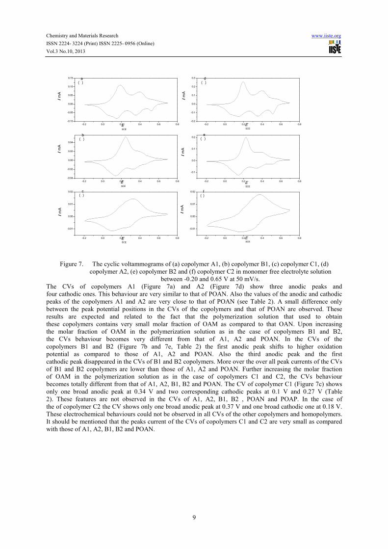
Figure 7 shows the CVs of copolymer A1, A2, B1, B2, C1 and C2. The CVs were recorded after
several potential cycles in the supporting electrolyte solution between 0.20 and 0.65 V until a stable CV
was established . The peak potential positions of the observed anodic and cathodic peak of the CVs
of copolymers (Figure 7) are summarized in Table 2 along with that of the CVs of homopolymers (Figures 1b,
2b, 3b and 4b).
Chemistry and Materials Research www.iiste.org
ISSN 2224- 3224 (Print) ISSN 2225- 0956 (Online)
Vol.3 No.10, 2013
9
-0.2 0.0 0.2 0.4 0.6 0.8
-0.10
-0.05
0.00
0.05
0.10
0.15(a )
I / m
A
ESCE
-0.2 0.0 0.2 0.4 0.6 0.8
-0.2
-0.1
0.0
0.1
0.2
0.3
(d )
I / m
A
ESCE
-0.2 0.0 0.2 0.4 0.6 0.8
-0.04
-0.02
0.00
0.02
0.04
(b )
I / m
A
ESCE
-0.2 0.0 0.2 0.4 0.6 0.8
-0.1
0.0
0.1
0.2
(e )
I / m
AE
SCE
-0.2 0.0 0.2 0.4 0.6 0.8
-0.01
0.00
0.01
0.02
(c )
I / m
A
ESCE
-0.2 0.0 0.2 0.4 0.6 0.8
-0.01
0.00
0.01
0.02
(f )
I / m
A
ESCE
Figure 7. The cyclic voltammograms of (a) copolymer A1, (b) copolymer B1, (c) copolymer C1, (d)
copolymer A2, (e) copolymer B2 and (f) copolymer C2 in monomer free electrolyte solution
between -0.20 and 0.65 V at 50 mV/s.
The CVs of copolymers A1 (Figure 7a) and A2 (Figure 7d) show three anodic peaks and
four cathodic ones. This behaviour are very similar to that of POAN. Also the values of the anodic and cathodic
peaks of the copolymers A1 and A2 are very close to that of POAN (see Table 2). A small difference only
between the peak potential positions in the CVs of the copolymers and that of POAN are observed. These
results are expected and related to the fact that the polymerization solution that used to obtain
these copolymers contains very small molar fraction of OAM as compared to that OAN. Upon increasing
the molar fraction of OAM in the polymerization solution as in the case of copolymers B1 and B2,
the CVs behaviour becomes very different from that of A1, A2 and POAN. In the CVs of the
copolymers B1 and B2 (Figure 7b and 7e, Table 2) the first anodic peak shifts to higher oxidation
potential as compared to those of A1, A2 and POAN. Also the third anodic peak and the first
cathodic peak disappeared in the CVs of B1 and B2 copolymers. More over the over all peak currents of the CVs
of B1 and B2 copolymers are lower than those of A1, A2 and POAN. Further increasing the molar fraction
of OAM in the polymerization solution as in the case of copolymers C1 and C2, the CVs behaviour
becomes totally different from that of A1, A2, B1, B2 and POAN. The CV of copolymer C1 (Figure 7c) shows
only one broad anodic peak at 0.34 V and two corresponding cathodic peaks at 0.1 V and 0.27 V (Table
2). These features are not observed in the CVs of A1, A2, B1, B2 , POAN and POAP. In the case of
the of copolymer C2 the CV shows only one broad anodic peak at 0.37 V and one broad cathodic one at 0.18 V.
These electrochemical behaviours could not be observed in all CVs of the other copolymers and homopolymers.
It should be mentioned that the peaks current of the CVs of copolymers C1 and C2 are very small as compared
with those of A1, A2, B1, B2 and POAN.
Chemistry and Materials Research www.iiste.org
ISSN 2224- 3224 (Print) ISSN 2225- 0956 (Online)
Vol.3 No.10, 2013
10
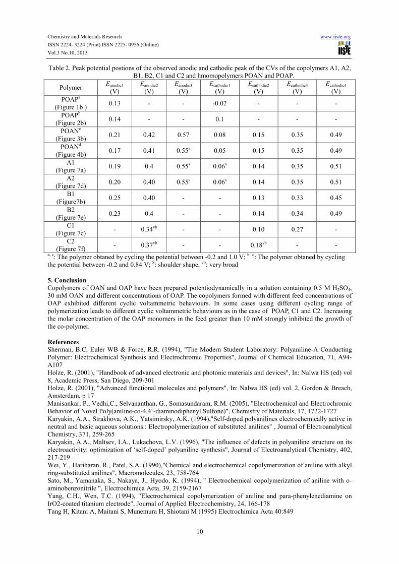
Table 2. Peak potential postions of the observed anodic and cathodic peak of the CVs of the copolymers A1, A2,
B1, B2, C1 and C2 and hmomopolymers POAN and POAP.
Polymer Eanodic1
(V)
Eanodic2
(V)
Eanodic3
(V)
Ecathodic1
(V)
Ecathodic2
(V)
Ecathodic3
(V)
Ecathodic4
(V)
POAPa
(Figure 1b ) 0.13 - - -0.02 - - -
POAPb
(Figure 2b) 0.14 - - 0.1 - - -
POANc
(Figure 3b) 0.21 0.42 0.57 0.08 0.15 0.35 0.49
POANd
(Figure 4b) 0.17 0.41 0.55
s 0.05 0.15 0.35 0.49
A1
(Figure 7a) 0.19 0.4 0.55
s 0.06
s 0.14 0.35 0.51
A2
(Figure 7d) 0.20 0.40 0.55
s 0.06
s 0.14 0.35 0.51
B1
(Figure7b) 0.25 0.40 - - 0.13 0.33 0.45
B2
(Figure 7e) 0.23 0.4 - - 0.14 0.34 0.49
C1
(Figure 7c) - 0.34
vb - - 0.10
0.27 -
C2
(Figure 7f) - 0.37
vb - - 0.18
vb - -
a, c: The polymer obtaned by cycling the potential between -0.2 and 1.0 V;
b, d: The polymer obtaned by cycling
the potential between -0.2 and 0.84 V; S: shoulder shape,
vb: very broad
5. Conclusion
Copolymers of OAN and OAP have been prepared potentiodynamically in a solution contain ing 0.5 M H2SO4,
30 mM OAN and different concentrations of OAP. The copolymers formed with different feed concentrations of
OAP exhibited different cyclic voltammetric behaviours. In some cases using different cycling range of
polymerization leads to different cyclic voltammetric behaviours as in the case of POAP, C1 and C2. Increasing
the molar concentration of the OAP monomers in the feed greater than 10 mM strongly inhibited the growth of
the co- polymer.
References
Sherman, B.C, Euler WB & Force, R.R. (1994), "The Modern Student Laboratory: Polyaniline-A Conducting
Polymer: Electrochemical Synthesis and Electrochromic Properties", Journal of Chemical Education, 71, A94-
A107
Holze, R. (2001), "Handbook of advanced electronic and photonic materials and devices", In: Nalwa HS (ed) vol
8, Academic Press, San Diego, 209-301
Holze, R. (2001), "Advanced functional molecules and polymers", In: Nalwa HS (ed) vol. 2, Gordon & Breach,
Amsterdam, p 17
Manisankar, P., Vedhi,C., Selvananthan, G., Somasundaram, R.M. (2005), "Electrochemical and Electrochromic
Behavior of Novel Poly(aniline-co-4,4‘-diaminodiphenyl Sulfone)", Chemistry of Materials, 17, 1722 -1727
Karyakin, A.A., Strakhova, A.K., Yatsimirsky, A.K. (1994),"Self-doped polyanilines electrochemically active in
neutral and basic aqueous solutions.: Electropolymerization of substituted anilines" , Journal of Electroanalytical
Chemistry, 371, 259-265
Karyakin, A.A., Maltsev, I.A., Lukachova, L.V. (1996), "The influence of defects in polyaniline structure on its
electroactivity: optimization of ‘self-doped’ polyaniline synthesis", Journal of Electroanalytical Chemistry, 402,
217-219
Wei, Y., Hariharan, R., Patel, S.A. (1990),"Chemical and electrochemical copolymerization of aniline with alkyl
ring-substituted anilines", Macromolecules, 23, 758-764
Sato, M., Yamanaka, S., Nakaya, J., Hyodo, K. (1994), " Electrochemical copolymerization of aniline with o-
aminobenzonitrile ", Electrochimica Acta. 39, 2159-2167
Yang, C.H., Wen, T.C. (1994), "Electrochemical copolymerization of aniline and para-phenylenediamine on
IrO2-coated titanium electrode", Journal of Applied Electrochemistry, 24, 166-178
Tang H, Kitani A, Maitani S, Munemura H, Shiotani M (1995) Electrochimica Acta 40:849

Chemistry and Materials Research www.iiste.org
ISSN 2224- 3224 (Print) ISSN 2225- 0956 (Online)
Vol.3 No.10, 2013
11
Si, S.H., Xu, Y.J., Nie, L.H., Yao, S.Z. (1995), "Electrochemical quartz crystal microbalance study on
electropolymerization of m-phenylenediamine: Effects of aniline and polyaniline", Electrochimica Acta, 40,
2715-2721
Kunimura, S., Ohsaka, T., Oyama, N. (1988), "Preparation of thin polymeric films on electrode surfaces by
electropolymerization of o-aminophenol", Macromolecules, 21, 894-900
Barbero C, Silber JJ, Sereno L (1989), " Formation of a novel electroactive film by electropolymerization of
ortho-aminophenol: Study of its chemical structure and formation mechanism. Electropolymerization of
analogous compounds ", Journal of Electroanalytical Chemistry, 263, 333- 352
Zhang, A.Q., Cui, C.Q., Chen, Y.Z., Lee, J.Y. (1994), "Synthesis and electrochromic properties of poly-o-
aminophenol", Journal of Electroanalytical Chemistry, 373, 115- 121
Pace, M.D. & Kim, O.K. (1988), "Conducting properties and electron paramagnetic resonance of
polyphenothiazine and polyphenoxazine ladder polymers", Synthetic Metals, 25, 333-339
Tucceri, R.I. (2004), "The change of the electron scattering at the gold film–poly-(o-aminophenol) film interface
after partial degradation of the polymer film: its relation with the electron transport process within the polymer
film", Journal of Electroanalytical Chemistry, 562, 173 -186
Barbero, C., Zerbino, J., Sereno, L., Posadas, D. (1987), "Optical properties of electropolymerized
orthoaminophenol", Electrochimica Acta, 32, 693 -697
Salavagione, H.J., Pardilla, J.A., Perez, J.M., Vazquez, J.L., Morallon, E., Miras, M.C., Barbero, C. (2005),
"Study of redox mechanism of poly(o-aminophenol) using in situ techniques: evidence of two redox processes",
Journal of Electroanalytical Chemistry, 576, 139 -145
Barbero, C., Tucceri, R.I., Posadas, D., Silbero, J.J., Sereno, L. (1995), "Impedance characteristics of poly-o-
aminophenol electrodes", Electrochimica Acta, 40, 1037 -1040
Mu, S. (2004), "Electrochemical copolymerization of aniline and o-aminophenol", Synthetic Metals, 143, 259 -
268
Ortega, J.M. (2000), "Conducting potential range for poly(o-aminophenol)", Thin Solid Films, 371, 28 -35
Mottoso, L.H.C. & Bulhoes, L.O.S. (1992), International Biomedical Information and Data, 52 171-183.
Shah, A. & Holze, R. (2006), "Copolymers and two-layered composites of poly(o-aminophenol) and
polyaniline", Journal of Solid State Electrochemistry, 11, 38–51
WEei, Y., Focke, W.W., Wnek, G.E., Ray, A., Mac Diarmid, A.G. (1989), " Synthesis and electrochemistry of
alkyl ring-substituted polyanilines", The Journal of Physical Chemistry, 93, 495.-499
Patil, S.F., Bedekar, A.G., Patil, R.C., Kher, J.A. (1997), "Effect of supporting electrolyte on the polymerization
of electrochemically deposited poly(o-anisidine) films", Journal of Materials Science, 32, 783-787
Stilwell, D.E. & Park S.M. (1988), "Electrochemistry of Conductive Polymers: II . Electrochemical Studies on
Growth Properties of Polyaniline", Journal of the Electrochemical Society, 135, 2254 -2262
CUI, C.Q., ONG, L.H., TAN, T.C., LEE, J.Y. (1993), " Extent of incorporation of hydrolysis products in
polyaniline films deposited by cyclic potential sweep ", Electrochimica Acta, 38, 1395-1404
This academic article was published by The International Institute for Science,
Technology and Education (IISTE). The IISTE is a pioneer in the Open Access
Publishing service based in the U.S. and Europe. The aim of the institute is
Accelerating Global Knowledge Sharing.
More information about the publisher can be found in the IISTE’s homepage:
http://www.iiste.org
CALL FOR JOURNAL PAPERS
The IISTE is currently hosting more than 30 peer-reviewed academic journals and
collaborating with academic institutions around the world. There’s no deadline for
submission. Prospective authors of IISTE journals can find the submission
instruction on the following page: http://www.iiste.org/journals/ The IISTE
editorial team promises to the review and publish all the qualified submissions in a
fast manner. All the journals articles are available online to the readers all over the
world without financial, legal, or technical barriers other than those inseparable from
gaining access to the internet itself. Printed version of the journals is also available
upon request of readers and authors.
MORE RESOURCES
Book publication information: http://www.iiste.org/book/
Recent conferences: http://www.iiste.org/conference/
IISTE Knowledge Sharing Partners
EBSCO, Index Copernicus, Ulrich's Periodicals Directory, JournalTOCS, PKP Open
Archives Harvester, Bielefeld Academic Search Engine, Elektronische
Zeitschriftenbibliothek EZB, Open J-Gate, OCLC WorldCat, Universe Digtial
Library , NewJour, Google Scholar

![3 all 1A).QP24.pdfWrite an equation to show the production of 4-aminophenol from 4-nitrophenol. Use [H] ... The flowchart below shows some reactions of 4-aminophenol. NH 3 ... shown](https://static.fdocuments.us/doc/165x107/607c53492aba8b596000ab7a/3-all-1-aqp24pdf-write-an-equation-to-show-the-production-of-4-aminophenol-from.jpg)


