Electro- Hydraulic Actuator Gas Valves GH-5000 - Dalemansdalemans.com/downloads/gh5000-gb_en.pdf ·...
28
SDI-Code: 130 4280 010 E Issue Date: 01/2004 Electro- Hydraulic Actuator Gas Valves GH-5000 Electro-Hydraulic Actuator Gas Valve GH-5000-.... Function Normally closed (NC). Single seat valve, fast closing, slow opening. Sturdy and reliable electro-hydraulic actuator. EC type-tested and certified as safety shut-off valve Class A (EN 161). Models • Threaded valve bodies Rp ¾ to Rp 3 and flanged valve bodies DN 40-150 • Actuator-Versions: - On - Off * / ** - On - Low - Off * - Ignition - On - Low - Off * Closed Position Indicator (CPI) available ** with switch for Manual Restart available Applications Typical applications include commercial and industrial boilers, burners, ovens, rooftop units, make up air heaters, hot water heaters, kilns, and paint booths. JCI Regelungstechnik GmbH Westendhof 3 D-45143 Essen Tel: +49 (0)201-2400 425 Fax: +49 (0)201-2400 429 www.johnsoncontrols.com
Transcript of Electro- Hydraulic Actuator Gas Valves GH-5000 - Dalemansdalemans.com/downloads/gh5000-gb_en.pdf ·...
SDI-Code: 130 4280 010 E Issue Date: 01/2004
Electro- Hydraulic Actuator Gas Valves GH-5000
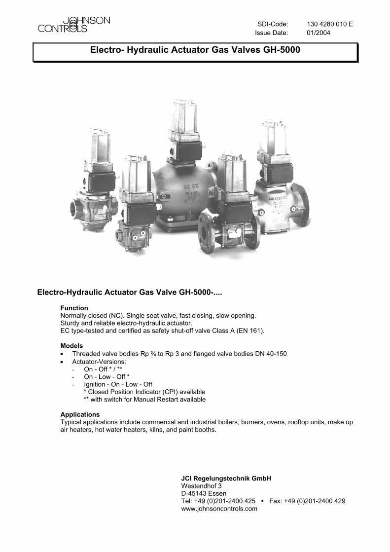
Electro-Hydraulic Actuator Gas Valve GH-5000-....
Function Normally closed (NC). Single seat valve, fast closing, slow opening. Sturdy and reliable electro-hydraulic actuator. EC type-tested and certified as safety shut-off valve Class A (EN 161). Models • Threaded valve bodies Rp ¾ to Rp 3 and flanged valve bodies DN 40-150 • Actuator-Versions:
- On - Off * / ** - On - Low - Off * - Ignition - On - Low - Off
* Closed Position Indicator (CPI) available ** with switch for Manual Restart available
Applications Typical applications include commercial and industrial boilers, burners, ovens, rooftop units, make up air heaters, hot water heaters, kilns, and paint booths.
JCI Regelungstechnik GmbH Westendhof 3 D-45143 Essen Tel: +49 (0)201-2400 425 Fax: +49 (0)201-2400 429 www.johnsoncontrols.com
E - 2 130 4280 010
Index Specifications ...................................................................................................................................................3 Code Key ...........................................................................................................................................................4 Safety Instructions ...........................................................................................................................................7 Installation.........................................................................................................................................................8 Wiring.................................................................................................................................................................9 Checkout Procedure.......................................................................................................................................10 Adjustments ....................................................................................................................................................11
Switch M........................................................................................................................................................11 Switch S ........................................................................................................................................................11 Switch R ........................................................................................................................................................12 Switch MR .....................................................................................................................................................12
Repairs and Replacement..............................................................................................................................13 DN 40-80 Flanged Body and All Threaded Body Models .............................................................................13 DN100-150 Flanged Body Models................................................................................................................15
Terminal Box Replacement ...........................................................................................................................16 Actuator Replacement....................................................................................................................................17 Spare Parts, Replacement Actuators ...........................................................................................................18 Troubleshooting .............................................................................................................................................20 Declaration of conformity ..............................................................................................................................21 Flow Characteristic flanged valve bodies....................................................................................................22 Flow Characteristic threaded valve bodies .................................................................................................24 Flow/Stroke Characteristic contour plug .....................................................................................................25 Dimensions and weight of flanged valve bodies DN40-150.......................................................................26 Dimensions of threaded valve bodies Rp ¾ to Rp 3...................................................................................27
130 4280 010 E E - 3
Specifications Product GH-5000 Electro-Hydraulic Actuator Valve Media Gas families to DVGW-Arbeitsblatt G 260/I. 1., 2. and 3. Gas family. Max. operating pressure Rp ¾ - 2 ½ & DN 40-65 1000 mbar
Rp 3 & DN 80-100 800 mbar DN 125 650 mbar DN 150 350 mbar
Permissible ambient temperature
-10 to +60°C (14 to 140°F)
Valve sizes Threaded connections Rp ¾, 1, 1 ½, 2, 2 ½, 3: ISO 7-1:1994 Flanges DN 40, 50, 65, 80, 100, 125, 150: ISO 7005 PN 16, DIN EN 1092-2
Valve torsion group Group 2 Valve class A Pressure taps Valve body: Rp 1/4 (ISO 7-1:1994) Materials Valve body: die-cast aluminium EN AC-43400 or
EN AC-47100, DIN EN 1706 (Rp ¾ to 2 and DN 40-50) cast iron EN-GJS-400-15, DIN EN 1563 (Rp 2½ to 3 and DN 65-80 and valves GH-57.. DN100-150) cast iron EN-GJL-250, DIN EN 1561 (valves GH-54.. DN100-150) Seals, diaphragm: NBR
Filter Standard Strainer: 1 mm (0.04 in). mesh (steel) Mounting position
Limited horizontal and vertical
90° max. fromverticaln
ATTENTION: See also Valve position label!
Operating voltages 120 V +6% / -10% 50/60 Hz 230 V +6% / -10% 50/60 Hz
Power consumption 200 W on opening action 15 W in opened state
Compression fitting EN 50262 Enclosure IP 54 (NEMA 1) Operating time rating 100% ED Duty cycles 3 min-1 (Rp ¾ - 1½, DN 40)
2 min-1 (Rp 2-3, DN 50-80) 1 min-1 (DN 100-150)
Opening time Rp ¾ - 1½, DN 40: < 6,5 s Rp 2-3, DN 50-80: < 8 s DN100-150: < 13 s
Closing time < 1 s Agency Listing EC-Type Approval Specification Standards Pressure Equipment (97/23/EC)
Appliances burning gaseous fuels (90/396/EC): EN 161 Electromagnetic compatibility (89/336/EC) Low voltage equipment (73/23/EC)
The performance specifications are nominal and conform to acceptable industry standards. For application at conditions beyond these specifications, consult the local Johnson Controls office. Johnson Controls, Inc. shall not be liable for damage resulting from misapplication or misuse of its products. We reserve the right to make technical changes without warning.
E - 4 130 4280 010 E
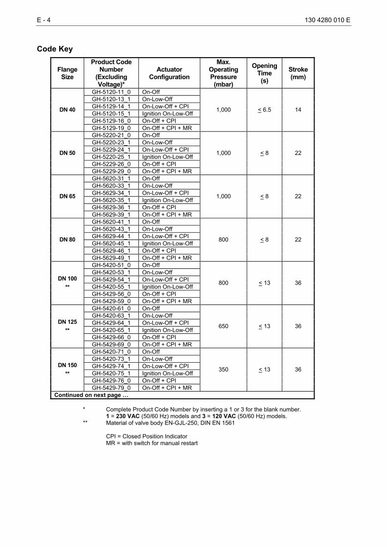
Code Key
Flange Size
Product Code Number
(Excluding Voltage)*
Actuator Configuration
Max. Operating Pressure
(mbar)
Opening Time (s)
Stroke (mm)
GH-5120-11_0 On-Off GH-5120-13_1 On-Low-Off GH-5129-14_1 On-Low-Off + CPI GH-5120-15_1 Ignition On-Low-Off GH-5129-16_0 On-Off + CPI
DN 40
GH-5129-19_0 On-Off + CPI + MR
1,000 < 6.5 14
GH-5220-21_0 On-Off GH-5220-23_1 On-Low-Off GH-5229-24_1 On-Low-Off + CPI GH-5220-25_1 Ignition On-Low-Off GH-5229-26_0 On-Off + CPI
DN 50
GH-5229-29_0 On-Off + CPI + MR
1,000 < 8 22
GH-5620-31_1 On-Off GH-5620-33_1 On-Low-Off GH-5629-34_1 On-Low-Off + CPI GH-5620-35_1 Ignition On-Low-Off GH-5629-36_1 On-Off + CPI
DN 65
GH-5629-39_1 On-Off + CPI + MR
1,000 < 8 22
GH-5620-41_1 On-Off GH-5620-43_1 On-Low-Off GH-5629-44_1 On-Low-Off + CPI GH-5620-45_1 Ignition On-Low-Off GH-5629-46_1 On-Off + CPI
DN 80
GH-5629-49_1 On-Off + CPI + MR
800 < 8 22
GH-5420-51_0 On-Off GH-5420-53_1 On-Low-Off GH-5429-54_1 On-Low-Off + CPI GH-5420-55_1 Ignition On-Low-Off GH-5429-56_0 On-Off + CPI
DN 100 **
GH-5429-59_0 On-Off + CPI + MR
800 < 13 36
GH-5420-61_0 On-Off GH-5420-63_1 On-Low-Off GH-5429-64_1 On-Low-Off + CPI GH-5420-65_1 Ignition On-Low-Off GH-5429-66_0 On-Off + CPI
DN 125 **
GH-5429-69_0 On-Off + CPI + MR
650 < 13 36
GH-5420-71_0 On-Off GH-5420-73_1 On-Low-Off GH-5429-74_1 On-Low-Off + CPI GH-5420-75_1 Ignition On-Low-Off GH-5429-76_0 On-Off + CPI
DN 150 **
GH-5429-79_0 On-Off + CPI + MR
350 < 13 36
Continued on next page … * Complete Product Code Number by inserting a 1 or 3 for the blank number. 1 = 230 VAC (50/60 Hz) models and 3 = 120 VAC (50/60 Hz) models. ** Material of valve body EN-GJL-250, DIN EN 1561 CPI = Closed Position Indicator MR = with switch for manual restart
130 4280 010 E E - 5
Flange Size
Product Code Number
(Excluding Voltage)*
Actuator Configuration
Max. Operating Pressure
(mbar)
Opening Time (s)
Stroke (mm)
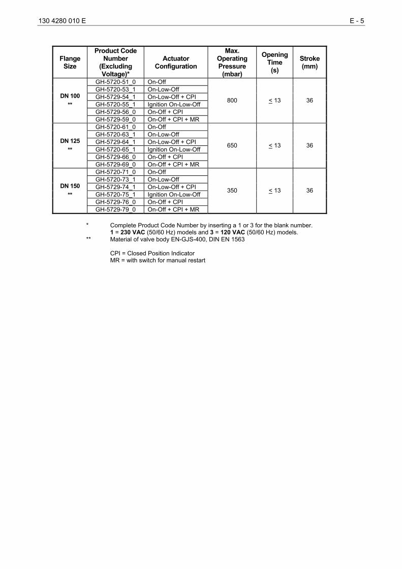
GH-5720-51_0 On-Off GH-5720-53_1 On-Low-Off GH-5729-54_1 On-Low-Off + CPI GH-5720-55_1 Ignition On-Low-Off GH-5729-56_0 On-Off + CPI
DN 100 **
GH-5729-59_0 On-Off + CPI + MR
800 < 13 36
GH-5720-61_0 On-Off GH-5720-63_1 On-Low-Off GH-5729-64_1 On-Low-Off + CPI GH-5720-65_1 Ignition On-Low-Off GH-5729-66_0 On-Off + CPI
DN 125 **
GH-5729-69_0 On-Off + CPI + MR
650 < 13 36
GH-5720-71_0 On-Off GH-5720-73_1 On-Low-Off GH-5729-74_1 On-Low-Off + CPI GH-5720-75_1 Ignition On-Low-Off GH-5729-76_0 On-Off + CPI
DN 150 **
GH-5729-79_0 On-Off + CPI + MR
350 < 13 36
* Complete Product Code Number by inserting a 1 or 3 for the blank number. 1 = 230 VAC (50/60 Hz) models and 3 = 120 VAC (50/60 Hz) models. ** Material of valve body EN-GJS-400, DIN EN 1563 CPI = Closed Position Indicator MR = with switch for manual restart
E - 6 130 4280 010 E
Threaded Size
Product Code Number
(Excluding Voltage)*
Actuator Configuration
Max. Operating Pressure
(mbar)
Opening Time (s)
Stroke (mm)
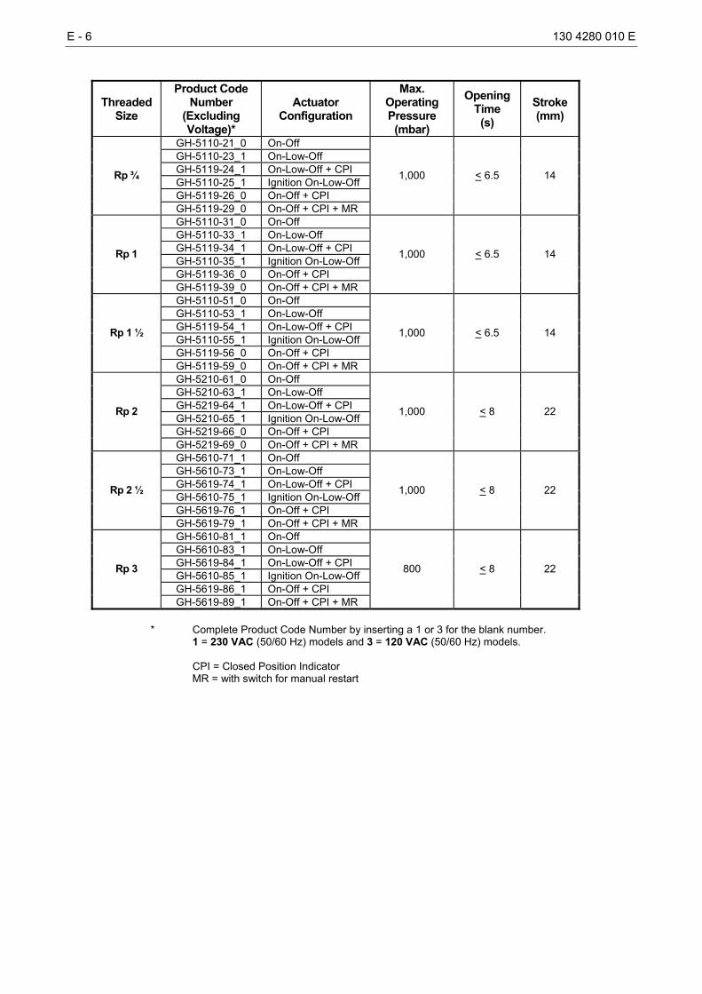
GH-5110-21_0 On-Off GH-5110-23_1 On-Low-Off GH-5119-24_1 On-Low-Off + CPI GH-5110-25_1 Ignition On-Low-Off GH-5119-26_0 On-Off + CPI
Rp ¾
GH-5119-29_0 On-Off + CPI + MR
1,000 < 6.5 14
GH-5110-31_0 On-Off GH-5110-33_1 On-Low-Off GH-5119-34_1 On-Low-Off + CPI GH-5110-35_1 Ignition On-Low-Off GH-5119-36_0 On-Off + CPI
Rp 1
GH-5119-39_0 On-Off + CPI + MR
1,000 < 6.5 14
GH-5110-51_0 On-Off GH-5110-53_1 On-Low-Off GH-5119-54_1 On-Low-Off + CPI GH-5110-55_1 Ignition On-Low-Off GH-5119-56_0 On-Off + CPI
Rp 1 ½
GH-5119-59_0 On-Off + CPI + MR
1,000 < 6.5 14
GH-5210-61_0 On-Off GH-5210-63_1 On-Low-Off GH-5219-64_1 On-Low-Off + CPI GH-5210-65_1 Ignition On-Low-Off GH-5219-66_0 On-Off + CPI
Rp 2
GH-5219-69_0 On-Off + CPI + MR
1,000 < 8 22
GH-5610-71_1 On-Off GH-5610-73_1 On-Low-Off GH-5619-74_1 On-Low-Off + CPI GH-5610-75_1 Ignition On-Low-Off GH-5619-76_1 On-Off + CPI
Rp 2 ½
GH-5619-79_1 On-Off + CPI + MR
1,000 < 8 22
GH-5610-81_1 On-Off GH-5610-83_1 On-Low-Off GH-5619-84_1 On-Low-Off + CPI GH-5610-85_1 Ignition On-Low-Off GH-5619-86_1 On-Off + CPI
Rp 3
GH-5619-89_1 On-Off + CPI + MR
800 < 8 22
* Complete Product Code Number by inserting a 1 or 3 for the blank number. 1 = 230 VAC (50/60 Hz) models and 3 = 120 VAC (50/60 Hz) models.
CPI = Closed Position Indicator MR = with switch for manual restart
130 4280 010 E E - 7
Safety Instructions Definition of symbols
This symbol indicates cautionary information. The statements WARNING, ATTENTION, CAUTION indicate a potentially hazardous situation with the risk of property damage, injuries or death.
WARNING: Carefully read and follow all instructions in this sheet and all instructions on the appliance. This unit must be installed by authorised service personnel in accordance with the regulations in force. Incorrect installation, adjustment, modification, operation or maintenance may cause fire, explosions, property damage, and injuries or death. All repairs, adjustments and servicing must be made in conjunction with the gas appliance and in accordance with the appliance manufacturer’s instructions. Keep operating instructions in a safe place.
CAUTION: It is possible to use fluids other than stated in the chapter Specifications but, this must first be confirmed by the manufacturer. In places where it is necessary to withstand high temperatures, the gas valves must be preceded for instance, by a thermally activated shutting-off device for gas. It may be necessary to discuss these measures with the manufacturer. • Storage and transport temperature -20°C to 65°C, dry and free of dirt. Protect the valve from adverse
weather conditions e.g. rain, splash water (otherwise use drying agent). • Protect against external forces (shock, Vibration etc.). Do not damage the surface • Ensure that valve body and piping are free of impurities, see also chapter Troubleshooting. • Ensure installation without tension and torque. • Do not use the valve as a step or fixation point. Only piping supports it. • Protect valve from dust or dirt on construction sites. Provide strainer or filter upstream of valve. • Use compensators to balance thermal expansion of piping.
E - 8 130 4280 010 E
Installation
WARNING: Explosion hazard. To prevent leakage of upstream gas, shut off the gas supply at the main manual shutoff valve before installing or servicing the GH-5000 valve.
CAUTION: Equipment damage. To prevent damage to the valve when mounting to pipework, do not use a wrench on any surface other than the casting flats provided at the inlet and outlet ends of the valve body. IMPORTANT: Ensure that the drilled holes in the actuator cover are not covered. These holes are necessary for ventilation and must not be covered by paint or other materials. Perform the following procedure to install the GH-5000 valve. • Ensure that the specified maximum ambient temperature is not exceeded (see Table 1). • Ensure that the power supply voltage is compatible with the required control valve voltage. • Ensure the gas flows through the valve body in the direction indicated by the arrow on the valve body.
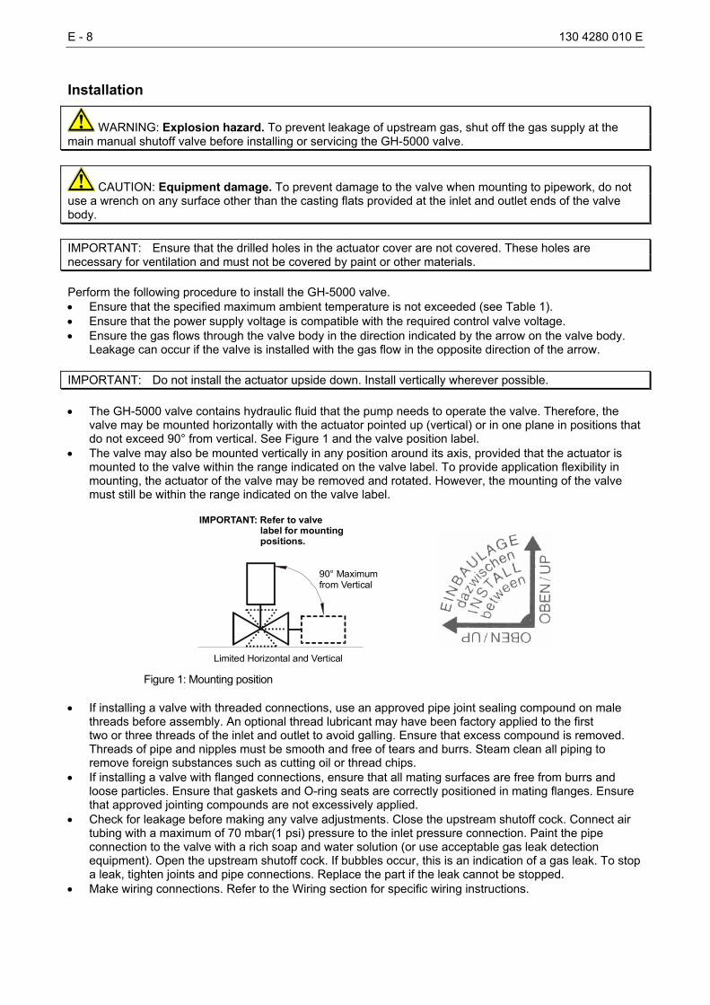
Leakage can occur if the valve is installed with the gas flow in the opposite direction of the arrow. IMPORTANT: Do not install the actuator upside down. Install vertically wherever possible. • The GH-5000 valve contains hydraulic fluid that the pump needs to operate the valve. Therefore, the
valve may be mounted horizontally with the actuator pointed up (vertical) or in one plane in positions that do not exceed 90° from vertical. See Figure 1 and the valve position label.
• The valve may also be mounted vertically in any position around its axis, provided that the actuator is mounted to the valve within the range indicated on the valve label. To provide application flexibility in mounting, the actuator of the valve may be removed and rotated. However, the mounting of the valve must still be within the range indicated on the valve label.
90° Maximumfrom Vertical
Limited Horizontal and Vertical
IMPORTANT: Refer to valve label for mounting positions.
Figure 1: Mounting position
• If installing a valve with threaded connections, use an approved pipe joint sealing compound on male threads before assembly. An optional thread lubricant may have been factory applied to the first two or three threads of the inlet and outlet to avoid galling. Ensure that excess compound is removed. Threads of pipe and nipples must be smooth and free of tears and burrs. Steam clean all piping to remove foreign substances such as cutting oil or thread chips.
• If installing a valve with flanged connections, ensure that all mating surfaces are free from burrs and loose particles. Ensure that gaskets and O-ring seats are correctly positioned in mating flanges. Ensure that approved jointing compounds are not excessively applied.
• Check for leakage before making any valve adjustments. Close the upstream shutoff cock. Connect air tubing with a maximum of 70 mbar(1 psi) pressure to the inlet pressure connection. Paint the pipe connection to the valve with a rich soap and water solution (or use acceptable gas leak detection equipment). Open the upstream shutoff cock. If bubbles occur, this is an indication of a gas leak. To stop a leak, tighten joints and pipe connections. Replace the part if the leak cannot be stopped.
• Make wiring connections. Refer to the Wiring section for specific wiring instructions.
130 4280 010 E E - 9
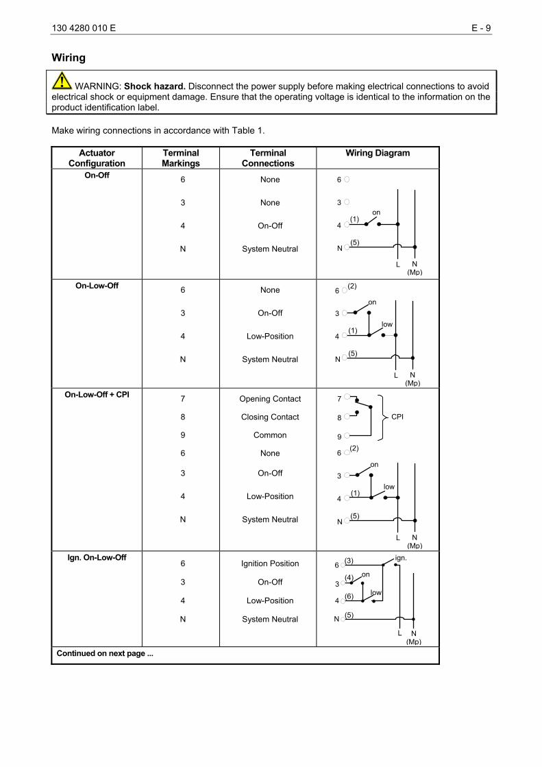
Wiring
WARNING: Shock hazard. Disconnect the power supply before making electrical connections to avoid electrical shock or equipment damage. Ensure that the operating voltage is identical to the information on the product identification label. Make wiring connections in accordance with Table 1.
Actuator Configuration
Terminal Markings
Terminal Connections
Wiring Diagram
On-Off 6
3
4
N
None
None
On-Off
System Neutral
6
on
L N(Mp)
(1)
(5)
3
4
N
On-Low-Off 6
3
4
N
None
On-Off
Low-Position
System Neutral
6
low
L N(Mp)
(2)
(5)
3
4
N
on
(1)
On-Low-Off + CPI 7
8
9
6
3
4
N
Opening Contact
Closing Contact
Common
None
On-Off
Low-Position
System Neutral
6
low
L N(Mp)
(2)
(5)
3
4
N
on
7
8
9
(1)
CPI
Ign. On-Low-Off
6
3
4
N
Ignition Position
On-Off
Low-Position
System Neutral
6
low
L N(Mp)
(3)
(5)
3
4
N
on(4)
(6)
ign.
Continued on next page ...
E - 10 130 4280 010 E
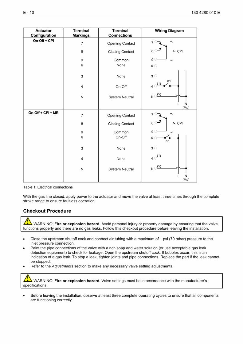
Actuator
Configuration Terminal Markings
Terminal Connections
Wiring Diagram
On-Off + CPI 7
8
9 6
3
4
N
Opening Contact
Closing Contact
Common None
None
On-Off
System Neutral
6
on
L N(Mp)
(1)
(5)
3
4
N
7
8
9
CPI
On-Off + CPI + MR
7
8
9 6
3
4
N
Opening Contact
Closing Contact
Common On-Off
None
None
System Neutral
6on
L N (Mp)
(1)
(5)
3
4
N
7
8
9
CPI
Table 1: Electrical connections
With the gas line closed, apply power to the actuator and move the valve at least three times through the complete stroke range to ensure faultless operation.
Checkout Procedure
WARNING: Fire or explosion hazard. Avoid personal injury or property damage by ensuring that the valve functions properly and there are no gas leaks. Follow this checkout procedure before leaving the installation. • Close the upstream shutoff cock and connect air tubing with a maximum of 1 psi (70 mbar) pressure to the
inlet pressure connection. • Paint the pipe connections of the valve with a rich soap and water solution (or use acceptable gas leak
detection equipment) to check for leakage. Open the upstream shutoff cock. If bubbles occur, this is an indication of a gas leak. To stop a leak, tighten joints and pipe connections. Replace the part if the leak cannot be stopped.
• Refer to the Adjustments section to make any necessary valve setting adjustments.
WARNING: Fire or explosion hazard. Valve settings must be in accordance with the manufacturer’s specifications. • Before leaving the installation, observe at least three complete operating cycles to ensure that all components
are functioning correctly.
130 4280 010 E E - 11
Adjustments
WARNING: All repairs, adjustments and servicing must be made in conjunction with the gas appliance and in accordance with the appliance manufacturer’s instructions. Only authorized personnel should make adjustments in accordance with the regulations in force.
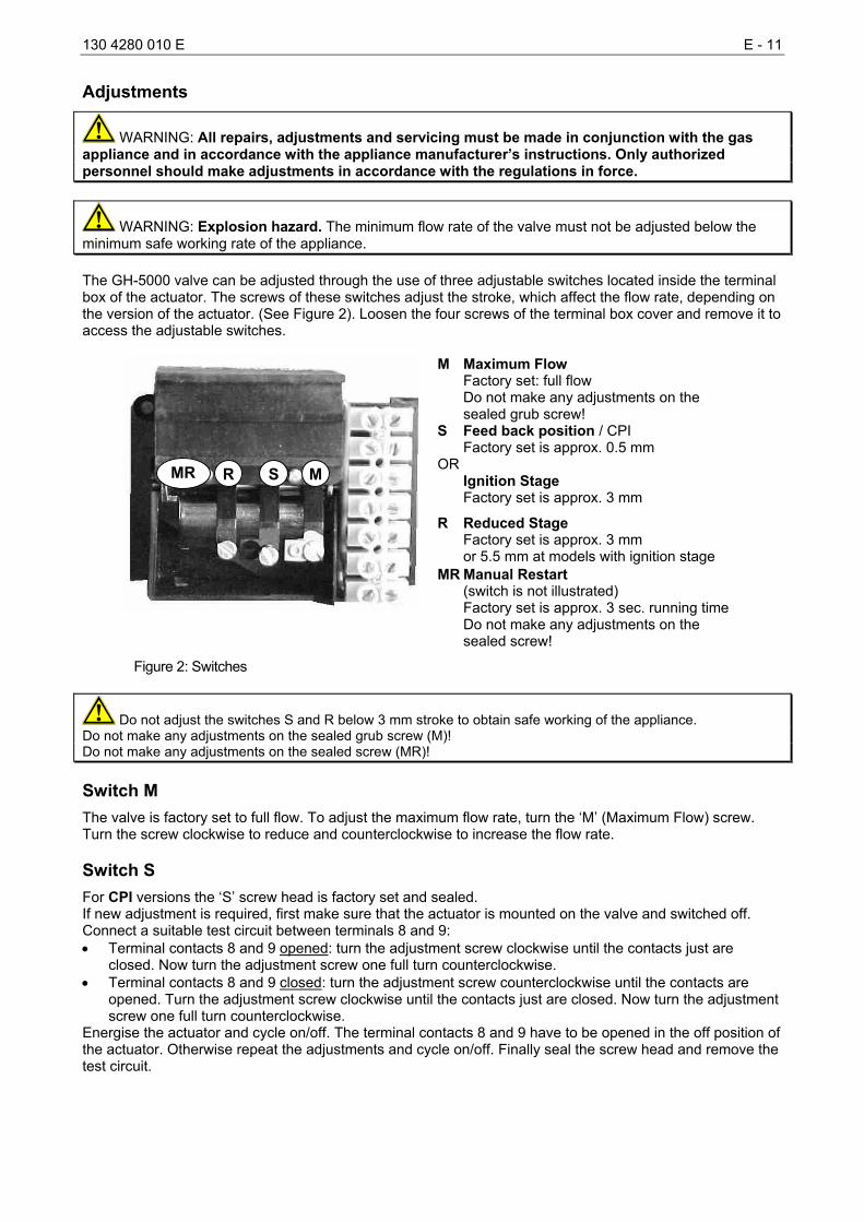
WARNING: Explosion hazard. The minimum flow rate of the valve must not be adjusted below the minimum safe working rate of the appliance. The GH-5000 valve can be adjusted through the use of three adjustable switches located inside the terminal box of the actuator. The screws of these switches adjust the stroke, which affect the flow rate, depending on the version of the actuator. (See Figure 2). Loosen the four screws of the terminal box cover and remove it to access the adjustable switches.
M Maximum Flow Factory set: full flow Do not make any adjustments on the sealed grub screw! S Feed back position / CPI Factory set is approx. 0.5 mm OR Ignition Stage Factory set is approx. 3 mm
R Reduced Stage Factory set is approx. 3 mm or 5.5 mm at models with ignition stage
MR Manual Restart (switch is not illustrated) Factory set is approx. 3 sec. running time Do not make any adjustments on the sealed screw!
Figure 2: Switches
Do not adjust the switches S and R below 3 mm stroke to obtain safe working of the appliance. Do not make any adjustments on the sealed grub screw (M)! Do not make any adjustments on the sealed screw (MR)!
Switch M The valve is factory set to full flow. To adjust the maximum flow rate, turn the ‘M’ (Maximum Flow) screw. Turn the screw clockwise to reduce and counterclockwise to increase the flow rate.
Switch S
For CPI versions the ‘S’ screw head is factory set and sealed. If new adjustment is required, first make sure that the actuator is mounted on the valve and switched off. Connect a suitable test circuit between terminals 8 and 9: • Terminal contacts 8 and 9 opened: turn the adjustment screw clockwise until the contacts just are
closed. Now turn the adjustment screw one full turn counterclockwise. • Terminal contacts 8 and 9 closed: turn the adjustment screw counterclockwise until the contacts are
opened. Turn the adjustment screw clockwise until the contacts just are closed. Now turn the adjustment screw one full turn counterclockwise.
Energise the actuator and cycle on/off. The terminal contacts 8 and 9 have to be opened in the off position of the actuator. Otherwise repeat the adjustments and cycle on/off. Finally seal the screw head and remove the test circuit.
R S M MR
E - 12 130 4280 010 E
In a similar way, the ‘S’ switch can be used as an auxiliary signal switch for any actuator stroke position. Turn the ‘S’ screw clockwise for a signal at a higher stroke or flow. Turning counterclockwise reduces stroke or flow level to activate the switch. To adjust the ignition flow, turn the ‘S’ screw. Turn the screw clockwise to reduce and counterclockwise to increase the flow required for proper ignition.
Switch R To adjust the reduced flow rate or low fire position, turn the ‘R’ (‘Reduced’) screw. Turn the screw clockwise to reduce and counterclockwise to increase the flow for stage one.
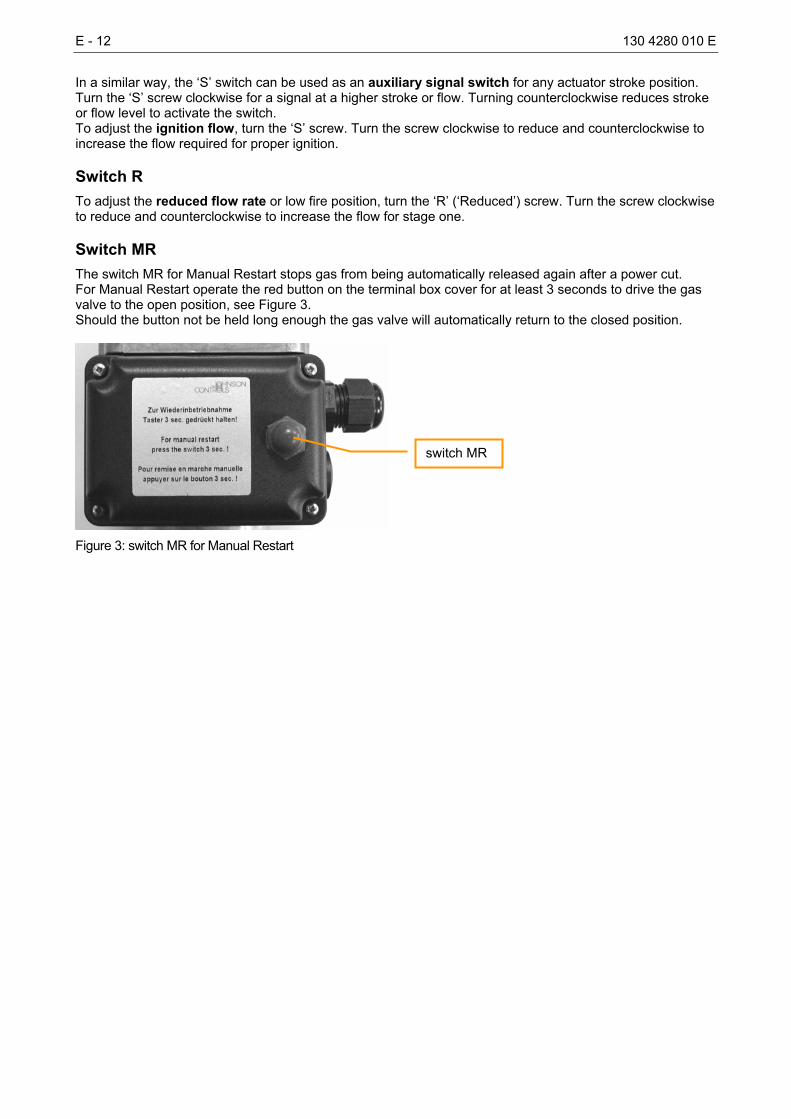
Switch MR The switch MR for Manual Restart stops gas from being automatically released again after a power cut. For Manual Restart operate the red button on the terminal box cover for at least 3 seconds to drive the gas valve to the open position, see Figure 3. Should the button not be held long enough the gas valve will automatically return to the closed position.
Figure 3: switch MR for Manual Restart
switch MR
130 4280 010 E E - 13
Repairs and Replacement
WARNING: All repairs, adjustments and servicing must be made in conjunction with the gas appliance and in accordance with the appliance manufacturer’s instructions. Only authorized personnel should make adjustments in accordance with the regulations in force. Field repairs must not be made, except to replace the filter, valve seat plug, gasket, terminal box, or actuator. For a replacement part, contact the nearest Johnson Controls representative or the original equipment manufacturer.
WARNING: Fire or explosion hazard. Shut off the gas supply at the main manual shutoff valve before servicing the valve. Only a trained service professional should perform these repair or replacement procedures. Valve Servicing Follow the model-specific procedure to service the valve. Perform this procedure with each recommended inspection or at a minimum each annual functional inspection.
DN 40-80 Flanged Body and All Threaded Body Models • Close the upstream shutoff cock and disconnect power to the actuator.
CAUTION: Personal injury hazard. The valve cover contains a compressed spring. Improper disassembly could cause the valve cover and spring to fly off resulting in personal injury or equipment damage. • Remove two diagonally opposed mounting screws from the bottom valve cover and replace them with
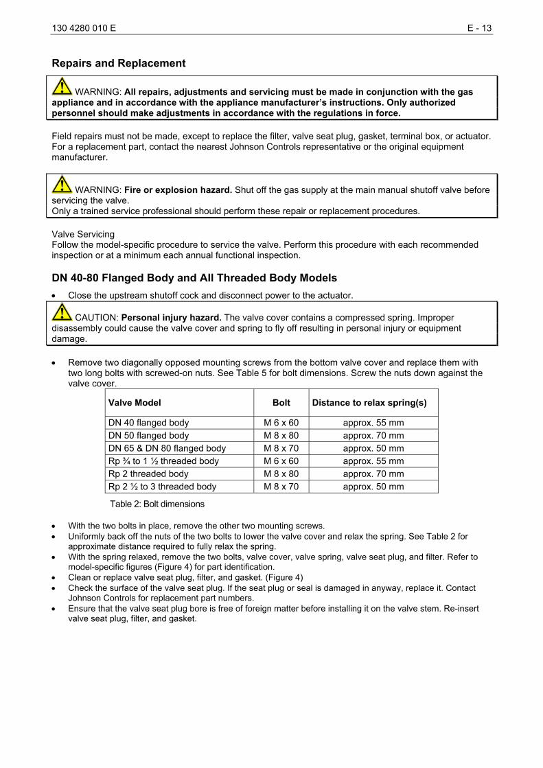
two long bolts with screwed-on nuts. See Table 5 for bolt dimensions. Screw the nuts down against the valve cover.
Valve Model Bolt Distance to relax spring(s)
DN 40 flanged body M 6 x 60 approx. 55 mm DN 50 flanged body M 8 x 80 approx. 70 mm DN 65 & DN 80 flanged body M 8 x 70 approx. 50 mm Rp ¾ to 1 ½ threaded body M 6 x 60 approx. 55 mm Rp 2 threaded body M 8 x 80 approx. 70 mm Rp 2 ½ to 3 threaded body M 8 x 70 approx. 50 mm
Table 2: Bolt dimensions
• With the two bolts in place, remove the other two mounting screws. • Uniformly back off the nuts of the two bolts to lower the valve cover and relax the spring. See Table 2 for
approximate distance required to fully relax the spring. • With the spring relaxed, remove the two bolts, valve cover, valve spring, valve seat plug, and filter. Refer to
model-specific figures (Figure 4) for part identification. • Clean or replace valve seat plug, filter, and gasket. (Figure 4) • Check the surface of the valve seat plug. If the seat plug or seal is damaged in anyway, replace it. Contact
Johnson Controls for replacement part numbers. • Ensure that the valve seat plug bore is free of foreign matter before installing it on the valve stem. Re-insert
valve seat plug, filter, and gasket.
E - 14 130 4280 010 E
• Place the valve spring inside the valve body and secure it with the valve cover and two opposing bolts. Ensure that the valve seat plug is not tilted.
• Uniformly tighten the nuts of the two bolts to raise the valve cover and compress the spring. • With the valve cover in position against the valve body, insert two of the mounting screws into the available
cover holes. • Remove the two bolts and replace them with the other two mounting screws. Ensure that the valve body and
cover are sealed. • Open the upstream shutoff cock and check for leakage along the valve cover. (Refer to the Checkout
Procedure section). • Observe at least three complete operating cycles to ensure that all components are functioning correctly.
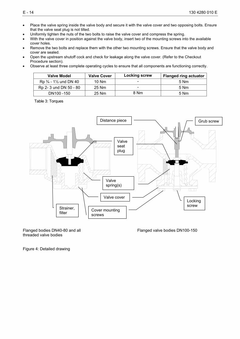
Valve Model Valve Cover Locking screw Flanged ring actuatorRp ¾ - 1½ und DN 40 10 Nm - 5 Nm
Rp 2- 3 und DN 50 - 80 25 Nm - 5 Nm DN100 -150 25 Nm 8 Nm 5 Nm
Table 3: Torques
Flanged bodies DN40-80 and all Flanged valve bodies DN100-150 threaded valve bodies Figure 4: Detailed drawing
Strainer, filter
Valve cover
Valve spring(s)
Distance piece
Valve seat plug
Locking screw
Grub screw
Cover mounting screws
130 4280 010 E E - 15
DN100-150 Flanged Body Models • Close the upstream shutoff cock and disconnect power to the actuator.
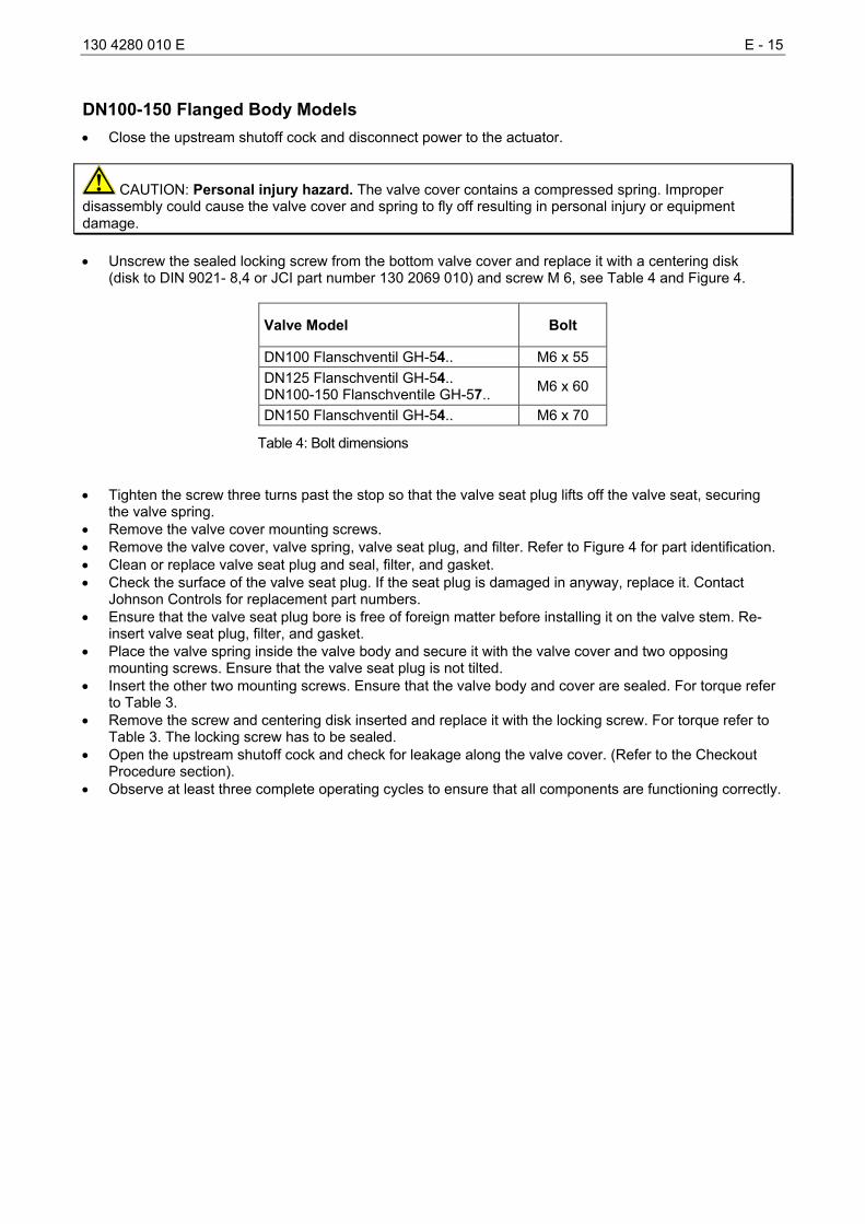
CAUTION: Personal injury hazard. The valve cover contains a compressed spring. Improper disassembly could cause the valve cover and spring to fly off resulting in personal injury or equipment damage. • Unscrew the sealed locking screw from the bottom valve cover and replace it with a centering disk
(disk to DIN 9021- 8,4 or JCI part number 130 2069 010) and screw M 6, see Table 4 and Figure 4.
Valve Model Bolt
DN100 Flanschventil GH-54.. M6 x 55 DN125 Flanschventil GH-54.. DN100-150 Flanschventile GH-57.. M6 x 60
DN150 Flanschventil GH-54.. M6 x 70
Table 4: Bolt dimensions
• Tighten the screw three turns past the stop so that the valve seat plug lifts off the valve seat, securing
the valve spring. • Remove the valve cover mounting screws. • Remove the valve cover, valve spring, valve seat plug, and filter. Refer to Figure 4 for part identification. • Clean or replace valve seat plug and seal, filter, and gasket. • Check the surface of the valve seat plug. If the seat plug is damaged in anyway, replace it. Contact
Johnson Controls for replacement part numbers. • Ensure that the valve seat plug bore is free of foreign matter before installing it on the valve stem. Re-
insert valve seat plug, filter, and gasket. • Place the valve spring inside the valve body and secure it with the valve cover and two opposing
mounting screws. Ensure that the valve seat plug is not tilted. • Insert the other two mounting screws. Ensure that the valve body and cover are sealed. For torque refer
to Table 3. • Remove the screw and centering disk inserted and replace it with the locking screw. For torque refer to
Table 3. The locking screw has to be sealed. • Open the upstream shutoff cock and check for leakage along the valve cover. (Refer to the Checkout
Procedure section). • Observe at least three complete operating cycles to ensure that all components are functioning correctly.
E - 16 130 4280 010 E
Terminal Box Replacement
CAUTION: Equipment damage hazard. Ensure that the replacement terminal box matches the existing one in every respect.
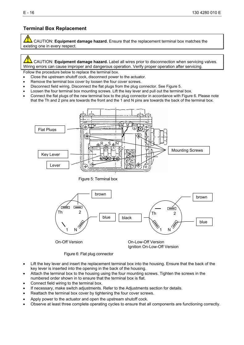
CAUTION: Equipment damage hazard. Label all wires prior to disconnection when servicing valves. Wiring errors can cause improper and dangerous operation. Verify proper operation after servicing. Follow the procedure below to replace the terminal box. • Close the upstream shutoff cock, disconnect power to the actuator. • Remove the terminal box cover by loosen the four cover screws. • Disconnect field wiring. Disconnect the flat plugs from the plug connector. See Figure 5. • Loosen the four terminal box mounting screws. Lift the key lever and pull out the terminal box. • Connect the flat plugs of the new terminal box to the plug connector in accordance with Figure 6. Please note
that the Th and 2 pins are towards the front and the 1 and N pins are towards the back of the terminal box.
Figure 5: Terminal box
On-Off Version On-Low-Off Version Ignition On-Low-Off Version
Figure 6: Flat plug connector
• Lift the key lever and insert the replacement terminal box into the housing. Ensure that the back of the key lever is inserted into the opening in the back of the housing.
• Attach the terminal box to the housing using the four mounting screws. Tighten the screws in the numbered order shown in to ensure that the terminal box is flat.
• Connect field wiring to the terminal box. • If necessary, make switch adjustments. Refer to the Adjustments section for details. • Reattach the terminal box cover by tightening the four cover screws.
• Apply power to the actuator and open the upstream shutoff cock. • Observe at least three complete operating cycles to ensure that all components are functioning correctly.
Th
N 1
2 Th
1
2
N
brown
blue blue
brown
black
Flat Plugs
Key Lever
Lever
Mounting Screws
130 4280 010 E E - 17
Actuator Replacement
CAUTION: Equipment damage hazard. Label all wires prior to disconnection when servicing valves. Wiring errors can cause improper and dangerous operation. Verify proper operation after servicing. Follow the procedure below to replace the actuator. • Close the upstream shutoff cock and disconnect power to the actuator. • Remove the terminal box cover by loosening four cover screws. • Disconnect field wiring. As you disconnect each wire, label it with the correct terminal designation. • Remove the four fixing screws from the flanged ring and lift off the actuator and flanged ring. • If the actuator is equipped with an extension piece: loosen the grub screw from the extension piece and
remove the extension piece from the actuator stem. See Figure 4.
CAUTION: Equipment damage hazard. The extension piece must be retained when replacing the actuator. The stem length is critical to proper closing of the valve. There must be a minimum clearance of 1 mm between the valve stem and valve seat plug. • Push the extension piece onto the stem of the replacement actuator and tighten the grub screw. • Place the actuator, without seal, onto the valve body. It must rest firmly on the valve body. If the actuator
does not rest firmly, clean the bore of the valve body. • Clean the seal and place it on the valve body. • Place the flanged ring and actuator on the valve body and loosely tighten the fixing screws (torque see
Table 3). • Turn the actuator to the preferred position and evenly tighten the fixing screws in a diagonally opposed
pattern. • Open the upstream shutoff cock and check for leakage along the flanged ring. (Refer to the Checkout
Procedure section). • Remove the cover of the terminal box by loosening the four cover screws. • Connect field wiring to the terminal box. • If necessary, make switch adjustments. Refer to the Adjustments section for details. • Reattach the terminal box cover by tightening the four cover screw. • Apply power to the actuator. • Observe at least three complete operating cycles to ensure that all components are functioning correctly.
E - 18 130 4280 010 E
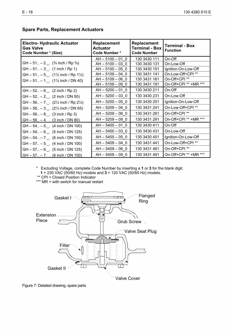
Spare Parts, Replacement Actuators Electro- Hydraulic Actuator Gas Valve Code Number * (Size)
Replacement Actuator Code Number *
Replacement Terminal - BoxCode Number
Terminal - Box Function
AH – 5100 – 01_0 130 3430 111 On-Off AH – 5100 – 03_0 130 3430 131 On-Low-Off AH – 5100 – 05_0 130 3430 151 Ignition-On-Low-Off AH – 5109 – 04_0 130 3431 141 On-Low-Off+CPI ** AH – 5109 – 06_0 130 3431 161 On-Off+CPI **
GH – 51.. – 2._. (¾ inch / Rp ¾) GH – 51.. – 3._. (1 inch / Rp 1) GH – 51.. – 5._. (1½ inch / Rp 1½) GH – 51.. – 1._. (1½ inch / DN 40)
AH – 5109 – 09_0 130 3431 191 On-Off+CPI ** +MR *** AH – 5200 – 01_0 130 3430 211 On-Off AH – 5200 – 03_0 130 3430 231 On-Low-Off AH – 5200 – 05_0 130 3430 251 Ignition-On-Low-Off AH – 5209 – 04_0 130 3431 241 On-Low-Off+CPI ** AH – 5209 – 06_0 130 3431 261 On-Off+CPI **
GH – 52.. – 6._. (2 inch / Rp 2) GH – 52.. – 2._. (2 inch / DN 50) GH – 56.. – 7._. (2½ inch / Rp 2½) GH – 56.. – 3._. (2½ inch / DN 65) GH – 56.. – 8._. (3 inch / Rp 3) GH – 56.. – 4._. (3 inch / DN 80) AH – 5209 – 09_0 130 3431 291 On-Off+CPI ** +MR ***
AH – 5400 – 01_0 130 3430 411 On-Off AH – 5400 – 03_0 130 3430 431 On-Low-Off AH – 5400 – 05_0 130 3430 451 Ignition-On-Low-Off AH – 5409 – 04_0 130 3431 441 On-Low-Off+CPI ** AH – 5409 – 06_0 130 3431 461 On-Off+CPI **
GH – 54.. – 5._. (4 inch / DN 100) GH – 54.. – 6._. (5 inch / DN 125) GH – 54.. – 7._. (6 inch / DN 150) GH – 57.. – 5._. (4 inch / DN 100) GH – 57.. – 6._. (5 inch / DN 125) GH – 57.. – 7._. (6 inch / DN 150) AH – 5409 – 09_0 130 3431 491 On-Off+CPI ** +MR ***
* Excluding Voltage, complete Code Number by inserting a 1 or 3 for the blank digit. 1 = 230 VAC (50/60 Hz) models and 3 = 120 VAC (50/60 Hz) models. ** CPI = Closed Position Indicator *** MR = with switch for manual restart
Gasket II
Valve Cover
Filter
Valve Seat Plug
Gasket I FlangedRing
Grub ScrewExtensionPiece
Figure 7: Detailed drawing, spare parts
130 4280 010 E E - 19
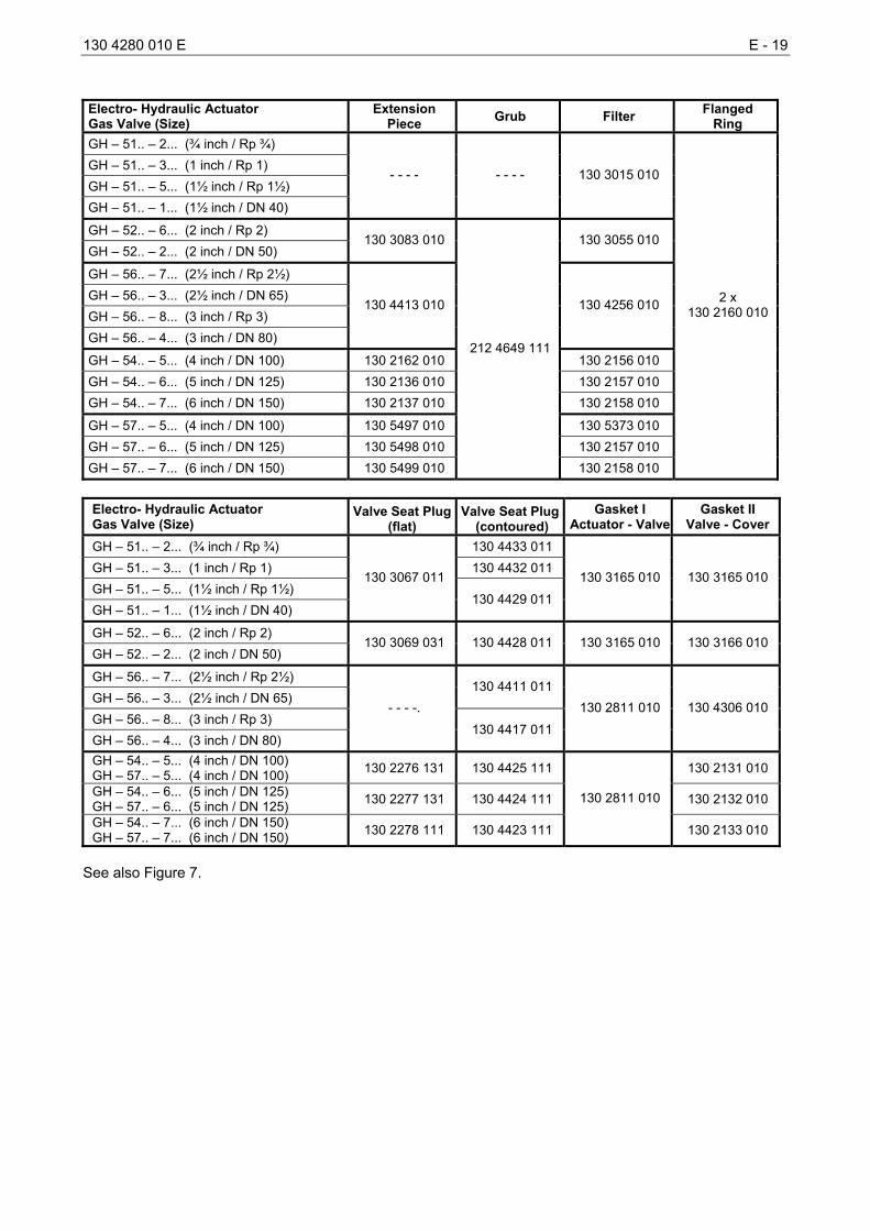
Electro- Hydraulic Actuator Gas Valve (Size)
Extension Piece Grub Filter Flanged
Ring GH – 51.. – 2... (¾ inch / Rp ¾) GH – 51.. – 3... (1 inch / Rp 1) GH – 51.. – 5... (1½ inch / Rp 1½) GH – 51.. – 1... (1½ inch / DN 40)
- - - - - - - - 130 3015 010
GH – 52.. – 6... (2 inch / Rp 2) GH – 52.. – 2... (2 inch / DN 50)
130 3083 010 130 3055 010
GH – 56.. – 7... (2½ inch / Rp 2½) GH – 56.. – 3... (2½ inch / DN 65) GH – 56.. – 8... (3 inch / Rp 3) GH – 56.. – 4... (3 inch / DN 80)
130 4413 010 130 4256 010
GH – 54.. – 5... (4 inch / DN 100) 130 2162 010 130 2156 010 GH – 54.. – 6... (5 inch / DN 125) 130 2136 010 130 2157 010 GH – 54.. – 7... (6 inch / DN 150) 130 2137 010 130 2158 010
GH – 57.. – 5... (4 inch / DN 100) 130 5497 010 130 5373 010 GH – 57.. – 6... (5 inch / DN 125) 130 5498 010 130 2157 010 GH – 57.. – 7... (6 inch / DN 150) 130 5499 010
212 4649 111
130 2158 010
2 x 130 2160 010
Electro- Hydraulic Actuator Gas Valve (Size)
Valve Seat Plug(flat)
Valve Seat Plug(contoured)
Gasket I Actuator - Valve
Gasket II Valve - Cover
GH – 51.. – 2... (¾ inch / Rp ¾) 130 4433 011 GH – 51.. – 3... (1 inch / Rp 1) 130 4432 011 GH – 51.. – 5... (1½ inch / Rp 1½) GH – 51.. – 1... (1½ inch / DN 40)
130 3067 011
130 4429 011
130 3165 010 130 3165 010
GH – 52.. – 6... (2 inch / Rp 2) GH – 52.. – 2... (2 inch / DN 50)
130 3069 031 130 4428 011 130 3165 010 130 3166 010
GH – 56.. – 7... (2½ inch / Rp 2½) GH – 56.. – 3... (2½ inch / DN 65)
130 4411 011
GH – 56.. – 8... (3 inch / Rp 3) GH – 56.. – 4... (3 inch / DN 80)
- - - -.
130 4417 011
130 2811 010 130 4306 010
GH – 54.. – 5... (4 inch / DN 100) GH – 57.. – 5... (4 inch / DN 100) 130 2276 131 130 4425 111 130 2131 010
GH – 54.. – 6... (5 inch / DN 125) GH – 57.. – 6... (5 inch / DN 125) 130 2277 131 130 4424 111 130 2132 010
GH – 54.. – 7... (6 inch / DN 150) GH – 57.. – 7... (6 inch / DN 150) 130 2278 111 130 4423 111
130 2811 010
130 2133 010
See also Figure 7.
E - 20 130 4280 010 E
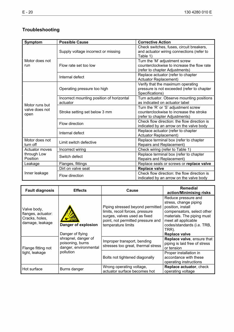
Troubleshooting Symptom Possible Cause Corrective Action
Supply voltage incorrect or missing Check switches, fuses, circuit breakers, and actuator wiring connections (refer to Table 1)
Flow rate set too low Turn the ‘M’ adjustment screw counterclockwise to increase the flow rate (refer to chapter Adjustments)
Motor does not run
Internal defect Replace actuator (refer to chapter Actuator Replacement)
Operating pressure too high Verify that the maximum operating pressure is not exceeded (refer to chapter Specifications)
Incorrect mounting position of horizontal actuator
Turn actuator. Observe mounting positions as indicated on actuator label
Stroke setting set below 3 mm Turn the ‘R’ or ‘S’ adjustment screw counterclockwise to increase the stroke (refer to chapter Adjustments)
Flow direction Check flow direction: the flow direction is indicated by an arrow on the valve body
Motor runs but valve does not open
Internal defect Replace actuator (refer to chapter Actuator Replacement)
Motor does not turn off Limit switch defective Replace terminal box (refer to chapter
Repairs and Replacement) Incorrect wiring Check wiring (refer to Table 1) Actuator moves
through Low Position Switch defect Replace terminal box (refer to chapter
Repairs and Replacement) Leakage Flanges, fittings Replace seals or screws or replace valve
Dirt on valve seat Replace valve Inner leakage Flow direction Check flow direction: the flow direction is
indicated by an arrow on the valve body
Fault diagnosis Effects Cause Remedial action/Minimising risks
Valve body, flanges, actuator: Cracks, holes, damage, leakage
Piping stressed beyond permitted limits, recoil forces, pressure surges, valves used as fixed point, not permitted pressure and temperature limits
Reduce pressure and stress, change piping position, install compensators, select other materials. The piping must meet all applicable codes/standards (i.e. TRB, TRR). Replace valve
Improper transport, bending stresses too great, thermal stress
Replace valve, ensure that piping is laid free of stress or tension Flange fitting not
tight, leakage
Danger of explosion Danger of flying shrapnel, danger of poisoning, burns danger, environmental pollution
Bolts not tightened diagonally Proper installation in accordance with these operating instructions
Hot surface Burns danger Wrong operating voltage, actuator surface becomes hot
Replace actuator, check operating voltage
130 4280 010 E E - 21
Declaration of conformity
E - 22 130 4280 010 E
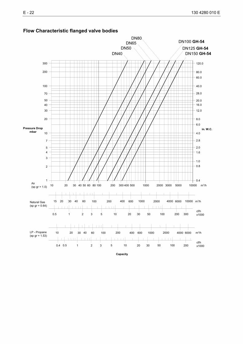
Flow Characteristic flanged valve bodies
m3/hAir (sp gr = 1.0) 10 20 30 40 50 60 80 100 200 300 400 500 1000
Natural Gas (sp gr = 0.64)
15 20 30 40 60 100 200 400 600 1000
cf/hx1000
m 3 /h
0.5 1 2 3 5 10 20 30
LP - Propane (sp gr = 1.53)
10 20 30 40 60 100 200 400 600 1000 m 3 /h
cf/hx10000.4 0.5 1 2 3 5 10 20 30
Capacity
in. W.C.Pressure Drop mbar
8.0
28.0
20.016.0
12.0
4.0
2.0 1.6
1.0 0.8
0.4
2.8
6.0
120.0
80.0
40.0
60.0
50 40 30
20
10
5 4 3
2
1
7
300
200
100
70
2000 3000 5000 10000
2000 4000 6000 10000
50 100 200 300
2000 4000 6000
50 100 200
DN40DN50
DN65 DN100 GH-54DN125 GH-54
DN150 GH-54
DN80
130 4280 010 E E - 23
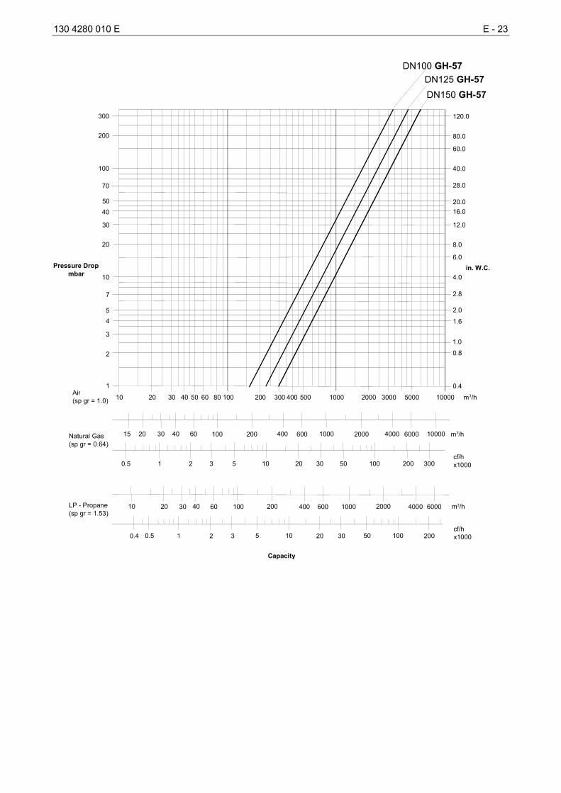
m3/hAir (sp gr = 1.0) 10 20 30 40 50 60 80 100 200 300 400 500 1000
Natural Gas (sp gr = 0.64)
15 20 30 40 60 100 200 400 600 1000
cf/hx1000
m 3 /h
0.5 1 2 3 5 10 20 30
LP - Propane (sp gr = 1.53)
10 20 30 40 60 100 200 400 600 1000 m 3 /h
cf/hx10000.4 0.5 1 2 3 5 10 20 30
Capacity
in. W.C.Pressure Drop mbar
8.0
28.0
20.016.0
12.0
4.0
2.0 1.6
1.0 0.8
0.4
2.8
6.0
120.0
80.0
40.0
60.0
50 40 30
20
10
5 4 3
2
1
7
300
200
100
70
2000 3000 5000 10000
2000 4000 6000 10000
50 100 200 300
2000 4000 6000
50 100 200
DN100 GH-57 DN125 GH-57DN150 GH-57
E - 24 130 4280 010 E
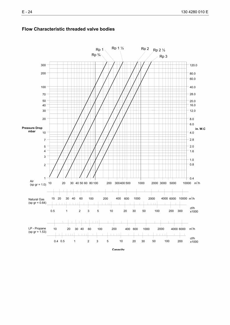
Flow Characteristic threaded valve bodies
m3/hAir(sp gr = 1.0) 10 20 30 40 50 60 80 100 200 300400 500 1000
Natural Gas(sp gr = 0.64)
15 20 30 40 60 100 200 400 600 1000
cf/hx1000
m3/h
0.5 1 2 3 5 10 20 30
LP - Propane(sp gr = 1.53)
10 20 30 40 60 100 200 400 600 1000 m3/h
cf/hx10000.4 0.5 1 2 3 5 10 20 30
Capacity
in. W.C.Pressure Dropmbar
8.0
28.0
20.016.0
12.0
4.0
2.01.6
1.00.8
0.4
2.8
6.0
120.0
80.0
40.0
60.0
5040
30
20
10
54
3
2
1
7
300
200
100
70
2000 3000 5000 10000
2000 4000 6000 10000
50 100 200 300
2000 4000 6000
50 100 200
Rp ¾Rp 1 Rp 1 ½ Rp 2 Rp 2 ½
Rp 3
130 4280 010 E E - 25
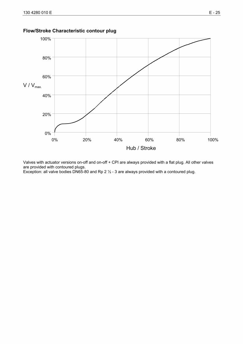
Flow/Stroke Characteristic contour plug
0% 20% 40% 60% 80% 100%0%
20%
100%
40%
60%
80%
Hub / Stroke
V / Vmax.
Valves with actuator versions on-off and on-off + CPI are always provided with a flat plug. All other valves are provided with contoured plugs. Exception: all valve bodies DN65-80 and Rp 2 ½ - 3 are always provided with a contoured plug.
E - 26 130 4280 010 E
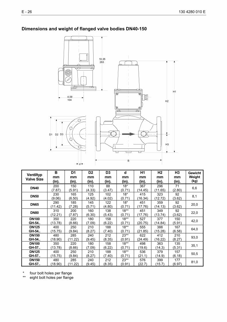
Dimensions and weight of flanged valve bodies DN40-150
H1
B
H2
H3
D1 D2 D3
d
4.09104
10.35 263
Ventiltyp Valve Size
B mm (in).
D1 mm (in).
D2 mm (in).
D3 mm (in).
d mm (in).
H1 mm (in).
H2 mm (in).
H3 mm (in).
GewichtWeight
(kg)
DN40 200 (7.87)
150 (5.91)
110 (4.33)
88 (3.47)
18* (0.71)
367 (14.45)
296 (11.65)
71 (2.80) 6,6
DN50 230 (9.06)
165 (6.50)
125 (4.92)
102 (4.02)
18* (0.71)
415 (16.34)
323 (12.72)
92 (3.62) 8,1
DN65 290 (11.42)
185 (7.28)
145 (5.71)
122 (4.80)
18* (0.71)
451 (17.76)
359 (14.13)
92 (3.62) 20,0
DN80 310 (12.21)
200 (7.87)
160 (6.30)
138 (5.43)
18** (0.71)
451 (17.76)
349 (13.74)
92 (3.62) 22,0
DN100 GH-54..
350 (13.78)
220 (8.66)
180 (7.09)
158 (6.22)
18** (0.71)
527 (20.75)
377 (14.84)
150 (5.91) 42,0
DN125 GH-54..
400 (15.75)
250 (9.84)
210 (8.27)
188 (7.40)
18** (0.71)
555 (21.85)
388 (15.28)
167 (6.58) 64,0
DN150 GH-54..
480 (18.90)
285 (11.22)
240 (9.45)
212 (8.35)
23** (0.91)
622 (24.49)
412 (16.22)
210 (8.27) 93,0
DN100 GH-57..
350 (13.78)
220 (8.66)
180 (7.09)
158 (6.22)
18** (0.71)
498 (19.6)
363 (14.3)
135 (5.31) 35,1
DN125 GH-57..
400 (15.75)
250 (9.84)
210 (8.27)
188 (7.40)
18** (0.71)
536 (21.1)
379 (14.9)
157 (6.18) 50,5
DN150 GH-57..
480 (18.90)
285 (11.22)
240 (9.45)
212 (8.35)
23** (0.91)
576 (22.7)
399 (15.7)
177 (6.97) 81,0
* four bolt holes per flange ** eight bolt holes per flange
130 4280 010 E E - 27
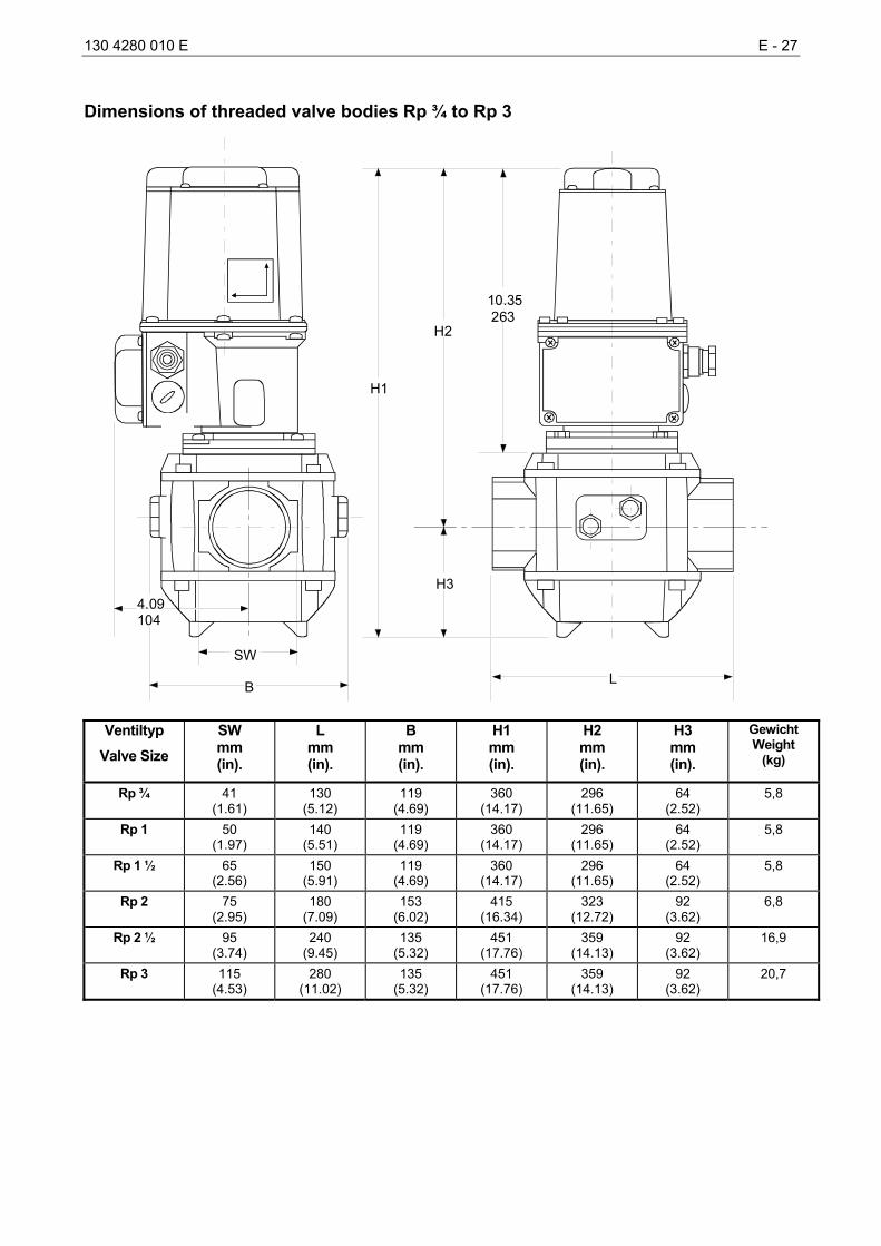
Dimensions of threaded valve bodies Rp ¾ to Rp 3
H1
L
10.35 263
SW
B
4.09104
H2
H3
Ventiltyp Valve Size
SW mm (in).
L mm (in).
B mm (in).
H1 mm (in).
H2 mm (in).
H3 mm (in).
Gewicht Weight
(kg)
Rp ¾ 41 (1.61)
130 (5.12)
119 (4.69)
360 (14.17)
296 (11.65)
64 (2.52)
5,8
Rp 1 50 (1.97)
140 (5.51)
119 (4.69)
360 (14.17)
296 (11.65)
64 (2.52)
5,8
Rp 1 ½ 65 (2.56)
150 (5.91)
119 (4.69)
360 (14.17)
296 (11.65)
64 (2.52)
5,8
Rp 2 75 (2.95)
180 (7.09)
153 (6.02)
415 (16.34)
323 (12.72)
92 (3.62)
6,8
Rp 2 ½ 95 (3.74)
240 (9.45)
135 (5.32)
451 (17.76)
359 (14.13)
92 (3.62)
16,9
Rp 3 115 (4.53)
280 (11.02)
135 (5.32)
451 (17.76)
359 (14.13)
92 (3.62)
20,7