Electro
7
Electronics design pcb production ● Producing the hello circuit boards: ● The assignment given here is producing a circuit boards that sends a message 'hello world' / the PCB board hello.echo.MTA.45. ● The second one was to produce and programm a circuit board which have LED and add a button for it which will be integrated with one of the keys from the computer./hello.echo MTA 44. -Since I have no that much background on electronics I needed to study a lot about it.
-
Upload
bereketnesh -
Category
Business
-
view
352 -
download
3
Transcript of Electro

Electronics design pcb production
● Producing the hello circuit boards:
● The assignment given here is producing a circuit boards that sends a message 'hello world' / the PCB board hello.echo.MTA.45.
● The second one was to produce and programm a circuit board which have LED and add a button for it which will be integrated with one of the keys from the computer./hello.echo MTA 44.
-Since I have no that much background on electronics I needed to study a lot about it.

Electronics design production ● Sending it to the modella machine:
First I opened the Cad py file and opened a hello 45 then opened a file from the input tool path.
I uncommented the highresolution for machining.Then on the CAM tool I opened the machine i.e. a modella machine.
Then I selected the tool diameter with 1/64 for cutting, speed x4,y4, contours -1 and changed the tool on the machine just as I set it on the CAD. Since I my board is sticked in the corner I put the position x2y2. After contouring I sent it to the machine.

PCB Production ● Components and Materials needed:
● 1. The printed circuit board
● 2.microcontroller = tiny 45
3.capacitor = C1 3.3UF
● 4. Resistor = R1 10K
● 5.voltage regulator=IC 2
● 6. connectors=4 & 5 legged Materials:
Components:
● Soldering iron
● Soldering wire
● Copper for cleaning brass and Clip
After printing the board I changed the setting and tool diameter by 1/32, to cut it. After I made the board out I collected the components.

PCB Production● Soldering
1. Stick the circuit board to your table by double sided tape -but not tightly because if it is tight it might be impossible for you to change the direction during soldering.
2. According to our/fablab Bcn experience, the best way to join the components to the circuitboard is to melt and drop the soldering wire on each point of *the circuit board first. This isbecause the wires will melt so quickly that you cant fix it no matter you tried to be quick.
3. Stick each components carefully *on the tip of each drop and press the component'sleg/tip by the solering iron. If you think the legs are not fixed well you can add more dropsof soldering wire on the top of its leg.
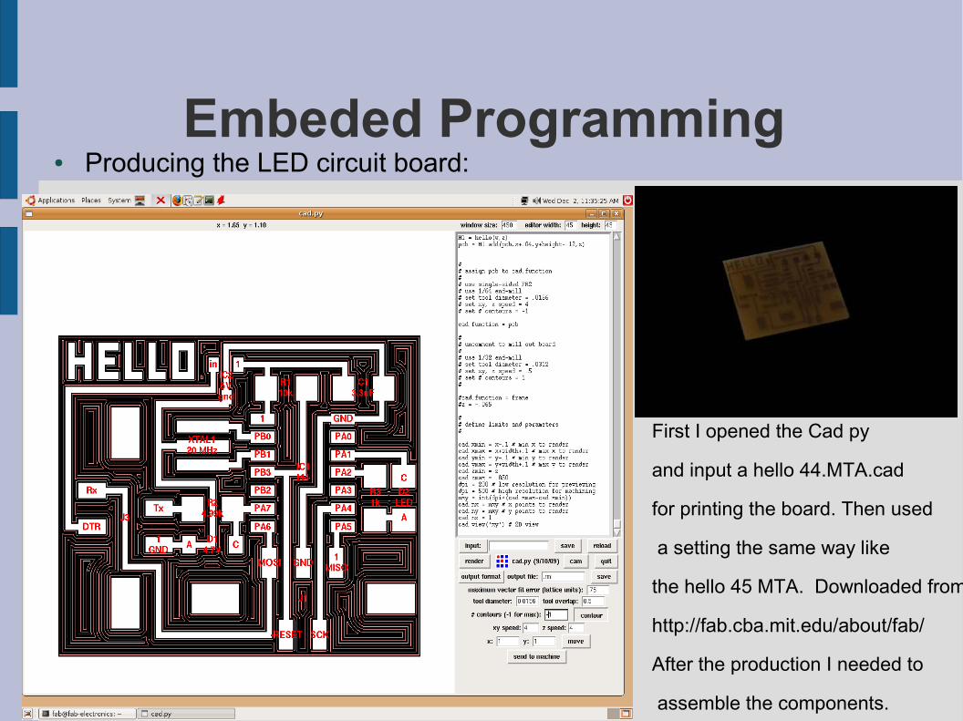
Embeded Programming● Producing the LED circuit board:
First I opened the Cad py
and input a hello 44.MTA.cad
for printing the board. Then used
a setting the same way like
the hello 45 MTA. Downloaded from
http://fab.cba.mit.edu/about/fab/
After the production I needed to
assemble the components.

● Producing Electronics1. Microcontroller- Tiny 442. Resistor1- R10K3. Resistor2- R 1K4. Resistor3- R 4.995. Capacotor- 3.3UF6. Voltage Regulator- 5V7. Resonator -20 MHZ8. D1- 4.7v9. D2- LED10.The printed circuit board
● On this part being aware of the polarity of the capacitor, LED and the resonator is very important, there is a line to distinguish that. I have been changing the direction and when programming it will not even read your board or the connection.

● Programming with Cad
● Adding the button:● This part was the hardest for me and still is because after making my third circuit
board it doesnt work yet. I am still working on it so I hope after many trials i will sucseed.
There are 3 fundemental steps
-Sending the power to the circuit board through the serial port,
-Sending the information from the the computer to the board through the parallel port,
-Reading the programmed information from the board/ 'mini computer' through the serial port.