Electrification promises a material reduction in running...
32
Transcript of Electrification promises a material reduction in running...

-- --
\ '.
~- - - -~ - "1 - --~

z
.. " ::;;:
~
'" >..J
U '" 0 0
z '" " :r
'" i-o i-o
" 0
'" 0 ..'" z 0
..J'" ~
i-o.. ~
" ..J " '" i-o" 0
" 7
'" ;:l
7" i-o ~ u 0 ~
u '" ;:l ~
z
" '"

A @pocA-in atlw~
cElectri icatiofL
G EN ER_-i L ELECTRI ceo YI P,-iNY SCHENECTADY NEW YORK
}j;df.!u: Yc;, /..1)/')
COprRIGH'T', /9/6
GENERAL ELEC'T'RIC COMPANr
\
L

Freight 'frain at
1)onald, the Summit ofthe Continental 1)i'oide
gr 1"r""""""''''''''''''''''''''''''''''''''''''i'IH ERE are no more thrilling and fascinating stories in American his
tory than those of the great transcontinental railway system. Masterly planning, unprecedented financing and marvelous engineering skill distinguished the early attempts to break through the great natural barrier between the Great Lakes country and the Pacific Coast. The execution
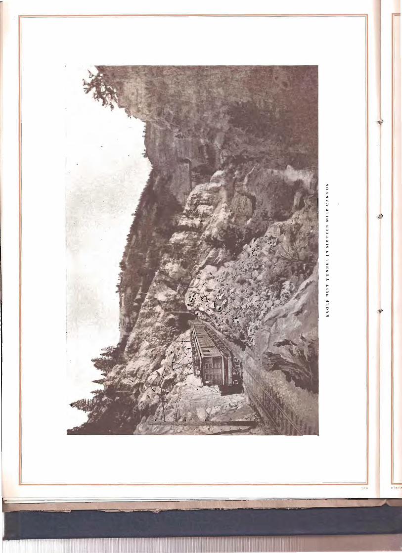
1,;;;;;;;;====....:.1 of these plans, extending over a long period of years, was a series of most remarkable accomplishments. Brilliant pioneering exploits marked the progress of surveyors, road builders, and operating force through the wilderness of mountains and desert. In the operation of the transcontinental railroad most serious problems have been encountered in lifting the fast increasing tonnage over the mile-high Rocky r.10untain Divide. In winter the deep snows and excessively cold weather have imposed almost insuperable obstacles.
The present era is eminently the electrical era. Electricity mines and refines our ores, 'fhe turns the wheels of our manufacturing plants, lights our cities and towns, transmits our CZeftrical messages, moves our urban and interurban cars, and when produced by water power it cra conserves our rapidly diminishing supply of coal. The change from steam to electricity for railroad transportation is not a theorist's fancy or a railroad president's whim; it is the logical result ofelectricity coming into its own. All the achievements in transcontinental railroad transportation in the past-and they have been many and marvelous-have been accomplished with steam locomotives, but today the steam locomotive is outclassed in power, in flexibility, in reliability, in ease of control, in economy, in comfort and in substantially every feature, by the electric locomotive. Therefore, the electrification of transcontinental railroads is a natural product of the electrical era.
J

Dectric Zone
'Passenger & Freight Tr[l.jfic
Nevertheless, it is a brilliant mile post on the road of progress in railroading, and there is more than a coincidence in the fact that the Chicago, Milwaukee & St. Paul Railway, which has many great pioneer achievements to its credit, should realize in actual accomplishment the aspirations cherished by the exponents of electricity decades ago.
While many terminal and tunnel installations have been made in the past for the purpose of eliminating smoke, taking care of suburban traffic or other local conditions, the Chicago, Milwaukee & St. Paul electrification is the first project of the kind where electric locomotives were installed to operate over several engine divisions.
The electrified 'Divisions The tracks of the mountain district of the Chicago, Milwaukee & St. Paul Rail
way,in surmounting the obstacles imposed by the Rocky Mountain and coastwise ranges, represent the solution of one of the most difficult problems ever mastered by railway engineers. Out of this section of rugged mountain railway, including many long grades and short radius curves, four steam engine divisions were selected for electrification, aggregating 440 miles in length. Steam engines were first abandoned on the Three Forks-Deer Lodge division, 115 miles long, and crossing the main Continental Divide, thus giving the electrical equipment its initial tryout under the severest service conditions of the entire system. The first electric locomotives were placed in regular service on December 9, 1915, and during the month of April, 1916, service was extended to Harlowton, making a total of 220 miles of electrically operated road. By the first of November, 1916, it is expected that steam engines will be superseded over the entire distance of 440 miles from Harlowton, Montana, to Avery, Idaho.
This project is the most extensive steam railway electrification in the world, the length of haul being nearly six times as great as any trunk line now operating with electric locomotives. The length of track between Harlowton, Montana, and Avery, Idaho, is approximately equal to that from New York to Buffalo or from Boston to Washington.
In crossing the three mountain ranges included in the electric zone, there are several grades of one per cen t or more, the most difficult of which is the 21 mile two per cent grade between Piedmont and Donald, and the longest the 49 mile one per cent grade on the west slope of the Belt Mountains.
The curvature is necessarily heavy, the maximum being 10 degrees. There are also numerous tunnels in the electric zone, 36 in all, of which the longest is the St. Paul Pass tunnel, over a mile and a half in length, through the ridge of the Bitter Root Mountains.
The passenger service consists of two all-steel finely equipped transcontinental trains in each direction, the « Olympian" and "Columbian," and a local passenger train in each direction daily between Deer Lodge and Harlowton.
Freight traffic through the electric zone comprises from four to six trains daily in each direction. Westbound, the tonnage is made up of manufactured products and merchandise for Pacific Coast points and foreign shipment. Eastbound tonnage includes grain, lumber, products of the mines and some live stock.

Freigh! 'Train
-u1seending Two Per Celt!
grade
As a larger part of the traffic is through freight, trains are made up of an assortment offoreign cars, including box and flat cars, coal and ore hoppers,stock cars,refrigerators, etc., varying in weight from I I to '25 tons empty and as high as 70 tons loaded. These cars being owned by many different railway systems are equipped with air brakes adjusted for different conditions of operation, and in accordance with different standards
Profile of Clearie Zone
(fcld'Creek Morel
1)irea
Current 1)istribution
l.:J.9 ?09:J t7~ 1;5.6 IZ • ,+file~ /rO/T1(:'orlO;.o.-ton lfor/owt(l(7

Trans
continental
Pas.renger
Train
"06'mpian" Climbing
the Rockies
Before Elec
trification
as to braking power and type of equipment, thus making the problem of holding the long trains on the heavy down grades by air brakes a most difficult one.
Electrical Operation Electrification promises a material reduction in running time. It has been found,
for example, that on the 2 I mile two per cent grade from Piedmont to Donald, the electric locomotive can reduce the running time of passenger trains from an hour and five minutes to approximately 40 minutes. On the run from Deer Lodge to Butte which, under the steam locomotive schedule, required an hour and 20 minutes, a saving of approximately 30 minutes can be made.
In the freight service, it has been found that on the first division where the steam locomotives have required 10 to 12 hours to make I 15 miles, electric locomotives can meet a schedule of from seven to eight hours for the same distance. The heavy grades and frequent curves at certain points offer serious obstacles to steam locomotive operation even in the summer time, but with winter temperatures as low as -400 F. and heavy snowfalls in the Bitter Root Mountains, serious delays have occurred, owing to engine failures or to inability to make steam. The capabilities of the electric locomotives are in no way impaired by cold weather or by inability to obtain fuel or water in case of snow blockades. During a series of record-breaking temperatures in December, 1915, lVlallet engines were frozen up at different points on the system and the new electric equipment was rapidly pressed into service to replace them. On several occasions electric locomotives hauled in disabled steam engines and trains which would otherwise have tied up the line.
" II I

'Train qf cight)'-two Freight Cars in Silver 'Bow Can)'on
During initial operation on the Rocky Mountain division, the capacity of the new locomotives has been thoroughly tested. Trains of 3000 tons trailing have been hauled east and 2800 tons west, using a helper on the heavy grades. From the operating data obtained on the first division, it is evident that much heavier trains can be
JII-steei Passenger Train " Of.ympian" at 'Deer
iJdge
11 . n
z o >z .., u W ...J
z
,"

Eustis Substation and Operators' Bungalows
hauled with the electric locomotives than with steam engines, and all passing tracks are being lengthened to take advantage of longer trains. On some of the runs where the grades are less than one per cent trains of as many as 130 cars and as heavy as 4000 tons have been hauled with a single locomotive.
The four through passenger trains, "Olympian" and" Columbian," are taken across the two mountain ranges by a single passenger locomotive. These trains at present consist of eight full vestibuled steel coaches, weighing approximately 650 tons. Instead of changing locomotives at Three Forks, as has been the practice under steam operation, the same locomotive is run through the 220 miles from Deer Lodge to Harlowton, changing crews midway. Passenger trains will travel over the entire electrified division in approximately 15 hours, including all stops, and the tourist thus will have an opportunity of traversing by daylight some of the most beautiful scenic regions in the United States and without suffering the annoyance of cinders and smoke incident to the use of steam locomotives.
The local passenger train operating in the electric zone between Deer Lodge and Harlowton is handled by a half unit weighing about 150 tons with equipment similar to the main line locomotives.
Concerning the first few months of operation, Mr. C. A. Goodnow, assistant to the President of the Chicago, NIilwaukee & St. Paul Railway, in charge of the electrification, has said: "Our electrification has been tested by the worst winter in the memory of modern railroaders. There were times when every steam locomotive in the Rocky Mountain district was frozen, but the electric locomotive went right along. Electrification has in every way exceeded our expectations. This is so, not only as respects tonnage handled and mileage made, but also the regularity of operation."

--MAPOF"-CHICAGO, MILWAUKEE & ST, PAUL .3000VOLT D,C ELECTRIFICAnON
-,sHO'NINGRAILWAY SUBSTATIONS. TRANSMISSION LINES.
. -ANOPOWER STATIONS.
~YMBOlS:- +RoilwoyS(/l)Uot.Jons. .lfydro-Electric Plant.,
- ~M;'IY(7v#ee&st.R7lJ//rf,tEledricZufle,
4 A::JtYerCOrrrpl':N"rlt'.:5ub:Jtot;o~
o lOwn.!) andCit;e s. - PowerCompony::J T/7:7/75rn/~~/]Line.::-, - /?otlwog 7h~l7.:JmIS$lo/]Line.
MAP
,,"" !/A
-'I i
".._:.C:_"::!~':""""::':"I"<~~_
0 f M 0 UN T A I N D J ST RIC T, CHI C A (; 0 l rvl J L \N AUK F. E & ST. P/\ U L ]{ A I I. WAY
~
~~ JI

~gen eJ' a t z· 0 n
Regeneration, or the recoven' of energy on the descending grades, by reversing the function of the electric motors reduces the cost of operation and furnishes a ready solution of the difficult braking problem. On the long sustained grades encountered in crossing the three mountain ranges, great skill is required to handle either the heavv and varied freight or the high speed passenger trains with the usual air brakes. The entire energy of the descending train must be dissipated by the friction of the brake shoes on the wheels, and it approximates 3500 kw. or 4700 h.p. for a 2500 ton train running at 17 miles per hour on a two per cent grade, thus explaining why brake shoes frequently become red-hot and other serious damage is done.
\Vith regenerative braking, the motors become generators which absorb the ~nergy
of the descending train and convert it into electricity, thus restricting the train to a safe speed dmvn the grade and at the same time returning electric power to the trolley for use by other trains. The strain on draw bars and couplings is reduced to a minimum since the entire train is bunched behind the locomotive and held to a uniform speed. The electric-braking mechanism automatically controls the speed by regulating the amount of energy fed back to the line. This smooth and easy descent is in marked contrast to the periodical slo\ving down and speeding up of a train controlled by air brakes.
The usual speed of the electrically hauled freight train is 15 miles per hour ascendi ng and 17 miles per hour descending the maximum grade, but half these speeds can easily be maintained with series connections of the motors should conditions require it.
Tn case there are no other trains between the substations to absorb the power generated by a descending train, this power passes through the substation machinery, is converted from direct to alternating current and fed into the distribution system connecting all substations. The Pmver Company's lines are so extensive and the load of such a diversified character that any surplus power returned by regenerating locomotives can readily be absorbed by the s:'stem; credit is given for aLl energy returned.
The advantages of regenerative braking may be summarized as follows:
Elimination of difficulties incident to the use of air brakes on heavy freight trains "hen descending mountain grades.
Elimination of brake shoe and wheel wear with resultant reduction in maintenance.
Reduced wear on tracks, especially on severe curves. ~-\ probable saving of approximately 15 per cent in the total power con
sumption. 1\laximum safety in operation assured by a duplicate braking systen1 reliev
ing the air brakes. The entire absence ofgrinding of the brakes which is especially disagreeable
on a heavy passenger train. Ino'eased comfort to passengers and reduced wear and tear on freight equi p
ment, owing to uniform speed on grades.
1.11'"t ..

•
The clectrz"cal cquz"pment
The scheme of electrification includes the generation of electricity from the several water po\yer plants of the l\/Iontana Power Company; transmission at 100,000 volts, three-phase, 60 cycles; conversion in the substations to 3000 volts direct current and distribution to electl'ic locomotives over catenary overhead construction.
Theachievementwhich Clef/ric has made the electrification
oftru nk Ii nes feasibleis primarily the development of the electric locomotive.
The main line Chicago, Milwaukee & St. Paul Rail way electric locomotives are
GE-25J-Li I500/3000
Yo!t 1'00tor
constructed in two units permanently coupled together, the halves being duplicates and each capable of independent operation. The enormous tractive effort of these electrical giants will be appreciated when it is stated that 50 years ago woodburning locomotives weighed 20 tons and had a tractive effort of only 5000 pounds. The modern :Mallet steam locomotive \yeighing 278 tons with tender, which has been released, has
a tractive force of 76,200 pounds, while the electric locomotive, weighing 282 tons, has a running tractive force of 85,000
Spring Gear pounds or a starting tractive force of136,000
pounds, There are 42 of these main line loco
motives (Jo freight and 12 passenger) and two switching locomotives. The locomotives are the first to be used for railroad service \vith direct current motors operating at a potential as high as *3000 volts and the first to use direct current regeneration. The passenger locomotives are equipped with a gear ratio permitting the operation of Soo-ton trailing trains at speeds ofapproximately 60 miles per hour on tangent level track. The average passenger trai n
>i' IllS of.interest to note that this is the first dir~cr current inS1J!l;ltion to US~;l jhHcntia{ as high as ;cco\-olts,;.tnd this equipment was adopted ~fter a car~fut investigation of all systems :t\'<lilablc for electritication. Th~ Butte, .-\n.1cond<l &: Pacific R:lih\"<l~', in the immediate vicinity ofth~ Chicago. \lilw:-\ukee & Sf. Paul e1ectrificatiOIl,has been in operation with '2~co-\·olt direct current loc(ll1loti\'~~ since :\Jay, I\)J.;, and h;\s fllrl1ished ;\Il
~,'\c("l\('nt .1 .... monslration of th< entire praclicabilit)' (If h!gh-\"oltage direct current 0jH.'r:l1il11l.

weighs from 650 to 700 tons and is hauled over the two per cent grade without a helper. The freight locomotives are designed to hau I a 2500 ton trailing train at approximately
,:f} 16 miles per hour on all grades up to / and including one per cent. On two
Sliding Pantograph Trolley
per cent grades the trailing load was limited to 1250 tons, although this figure has been exceeded in actual operation.
Each locomotive is equipped with eight Type GE-2 53 -A, 15oo-volt motors, insulated for 3000 volts to ground. This motor has a normal one hour rating of 430 h.p. and a continuous rating of 375 h. p., so that the locomotive power plant has a normal one hour rating of 3440 h.p. and a
" continuous rating of 3000 h.p. Each motor is twin geared to its driving axle in the same manner as on the Butte, Anaconda & Pacific, the Detroit River Tunnel, and the Baltimore & Ohio locomotives, a pinion being mounted on each end of the armature shaft. Additional flexibility is obtained by the use of a spring gear and a spring nose suspension which minimize the eB-ect of all shocks and also reduce gear wear to a minimum. The motor is of the commutating-pole type and is constructed with longitudinal ventilating ducts in the armature for forced ventilation from a blower in the cab.
The control equipment is the \vell-known Sprague General Electric Type 1\1 arranged for multiple unit operation. The main control s\vitches are mou 11 ted in steel com partl1l ents inside of the locomotive cab \vith COI1
venien t aisles for inspection and repairs. In each half of the locomotive a motor-generator set furnishes 10\\'
voltage current for the control circuits, headlights, cab lighting and for charging the storage batteries on passenger coaches. Under steam operation, the charging currel1t for these batteries is furnished by the steam turbo-generator set located in the baggage car. The blO\ver for ventilating the traction motors is also direct connected to one end of this set.
Jl(otors
and Control
engineer's Cab
f: It,· t' ~ I
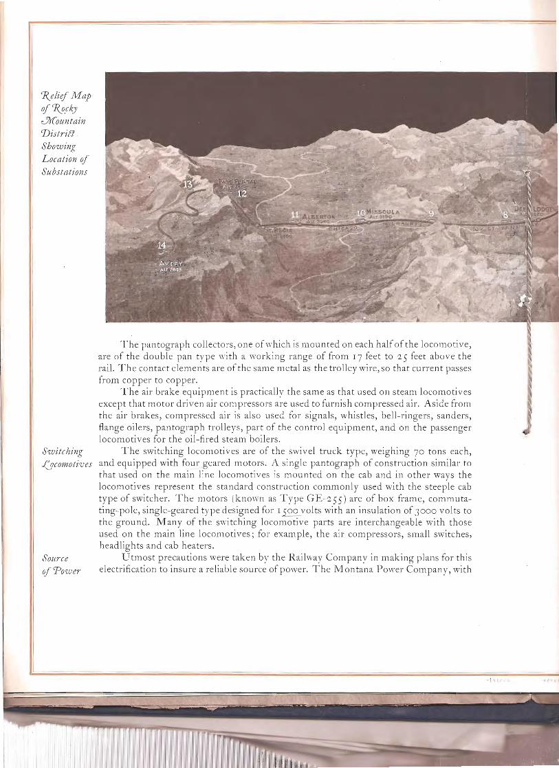
1\elief .11.-1ap
of~ck)'
.Jr(ountain 1)istrilJ
Showing
Location of
Substations
T he pan tograph collectors, one of which is mou nted on each half of the locomoti ve, are of the double pan type with a working range of from 17 feet to 25 feet above the rail. The contact elements are of the same metal as the trolley wire,so that current passes from copper to copper.
The air brake equipment is practically the same as that used on steam locomotives except that motor driven air compressors are used to furnish compressed air. Aside from the air brakes, compressed air is also used for signals, whistles, bell-ringers, sanders, flange oilers, pantograph trolleys, part of the control equipment, and on the passenger locomotives for the oil-fired steam boilers.
Switching The switching locomotives are of the swivel truck type, weighing 70 tons each, ~{)cornoti'ves and equipped with four geared motors. A single pantograph of construction similar to
that used on the main line locomotives is mounted on the cab and in other ways the locomotives represent the standard construction commonly used with the steeple cab type of switcher. The motors (known as Type GE-2SS) are of box frame, commutating-pole, single-geared type designed for I 00 volts with an insulation of JOOO volts to the ground. Many of the switching locomotive parts are interchangeable with those used on the main line locomotives; for exam pie, the air com pressors, small switches, headlights and cab heaters.
Source Utmost precautions were taken by the Railway Company in making plans for this
of 'Power electrification to insure a reliable source of power. The Montana Power Company, "vith
; \1
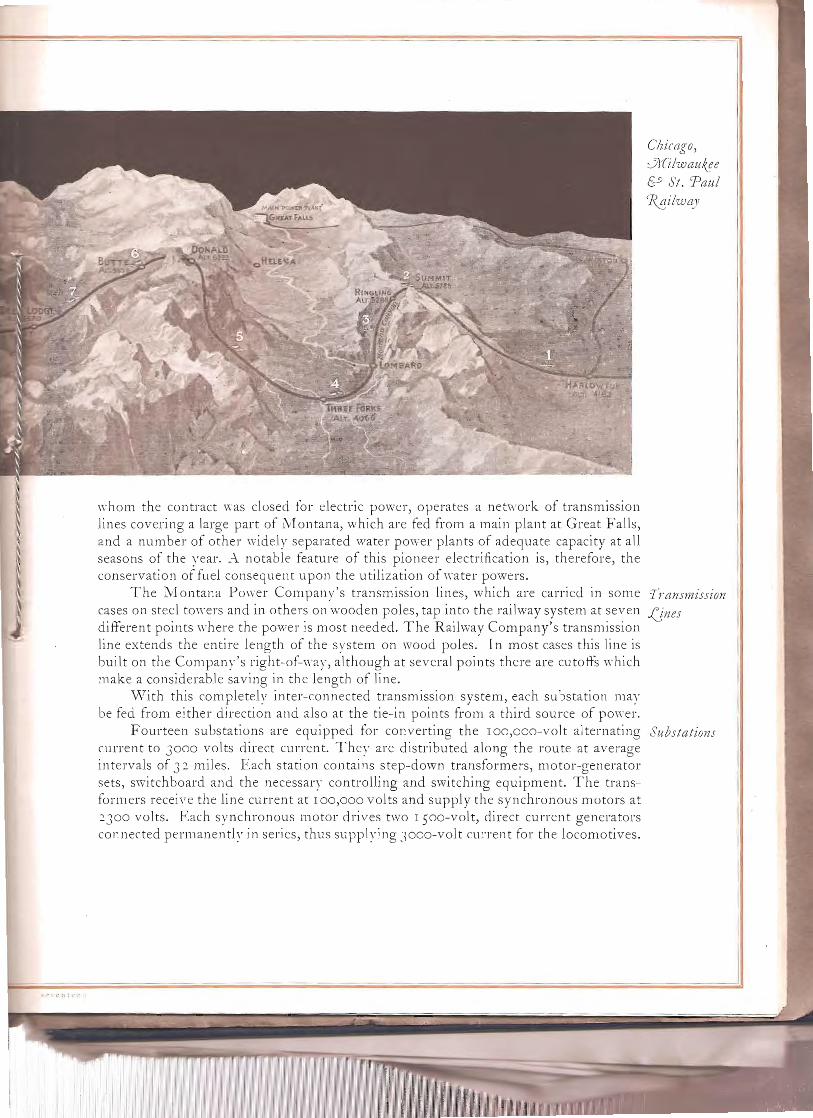
Clzicago, JJfilwaul(!e &9 St. 'Paul '7V!i!way
,,-hom the contract was closed for electric power, operates a network of transmission lines covering a large part of l\tlontana, which are fed from a main plant at Great Falls, and a number of other \videly separated water power plants of adequate capacity at all seasons of the year..-\ notable feature of this pioneer electrification is, therefore, the conservation of fuel consequent upon the utilization of \vater powers.
The l\tIontana PO\ver Company's transmission lines, which are carried in some TraNsmission cases on steel to\vers and in others on wooden poles, tap into the railway system at seven ,(Jnes different points \vhere the power is most needed. The Railviay Company's transmission line extends the entire length of the system on wood poles. In most cases this line is built on the Company's right-of-way, although at several points there are cutoffs which make a considerable saving in the length of line.
\'Vith this completely inter-connected transmission system, each substation may be fed from either direction and also at the tie-in points from a third source of power.
Fourteen substations are equipped for converting the IOO,ooo-volt alternating Substations current to 3000 volts direct current. They are distributed along the route at average intervals of 3 2. miles. Each station contains step-down transformers, motor-generator sets, switchboard and the necessary controlling and switching equipment. The transformers receive the line current at 100,000 volts and supply the synchronous motors at 2300 volts. Each synchronous motor drives two 1soo-volt, direct current generators connected permanentl)' in series, thus supplying 3000-volt current for the locomotives.

t t' I

TJIO IiH!ild
E(j/O~iJ aIt
:.5)(otOj
0'eneratljl"
Sets iii :.5) (oJ"e!
SlIbJ,tatlOll
The fields of both the s,"nchronous motors and the direct current generators are separatel:: excited by small direct current generators direct connected to each end of the motor-generator shafts.
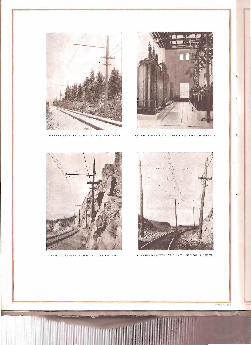
The overhead construction is of the modified flexible catenary type designed by (f-.;ei'liecId the General Electric Company and installed under the direction of the Raihvay Com CrJil stl'Iitlion pany's engineers. \,Vith this quite novel but remarkably successful construction, the current is co:lected in both high speed passenger service and heavy freight service without any sparking. As may be seen from the illustrations, the construction comprises two + 0 copper \yires flexibl~' suspended side bv side from the same steel messenger b~'
independent hangers alternatel~' connected to each wire. Bracket construction is used \\·herever the track alignment will permit, and cross span construction on passing tracks and in the switching Yards. All of this ,york is supported on 40-foot wooden poles suitabh' guyed and spaced.
Electric locomotion has been adopted by the Chicago, Milwaukee & St. Paul Rail Cos; \yay as "a ne\yer, better foundation on which builders shall rear the structure of railroading to undreamed-of efficiency and comfort." The enterprise has been undertaken with the expectation of effecting a sufficient reduction in the cost of operation to return an attractive percentage on the investment required, as well as to benefit by all the operating advantages of electric locomotives .•-\ccording to statements made by the railroad officials, about S 12,000,000 will be expended, and with the work more than half completed there is every reason to believe that the cost of construction will come inside the estimates.
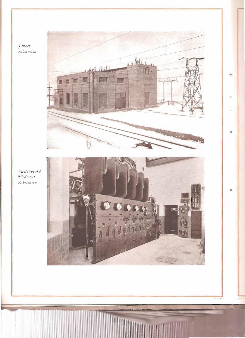
Janne.l'
Substation
'~
Switc!zboard Piedmont Substation
t".(t' 11\

/�
u'fdvantages if tteElr~fication
j\'larked reduction in cost of electricity as compared with cost of coal. Reduction in maintenance cost of locomotives. Elimination of delays due to coaling, taking water, oil, etc. Elimination of delays due to natural causes, such as freezing of locomo
tives, loss of steam in cold weather, bucking snow drifts. Elimination of non-revenue trains hauling coal and water for steam loco
motives. Increased tonnage per train. Increased trai n speed on grades. Greater reliability and certainty of maintaining schedules. Reduction in train crew hours per ton mile. Reduction in damage to rolling stock due to rough handling by steam en
g1l1es. Greatly increased safety of operation on grades due to regenerative braking. Saving in power and reduction in wheel and track wear by use of regenera
tive braking. Improvement of tunnel conditions due to smoke and gas, absence of smoke
and cinders which obscure scenic attractions, uniform speed and absence of grinding brake shoes on grades, all of which accrue to the benefit of the traveler on the transcontinental passenger trains .
Trolley Construftion
O'L-'er JVine
Tracks in 7)eer iJdge Yards
Summary
• n t~· - 0 n.:
--
----
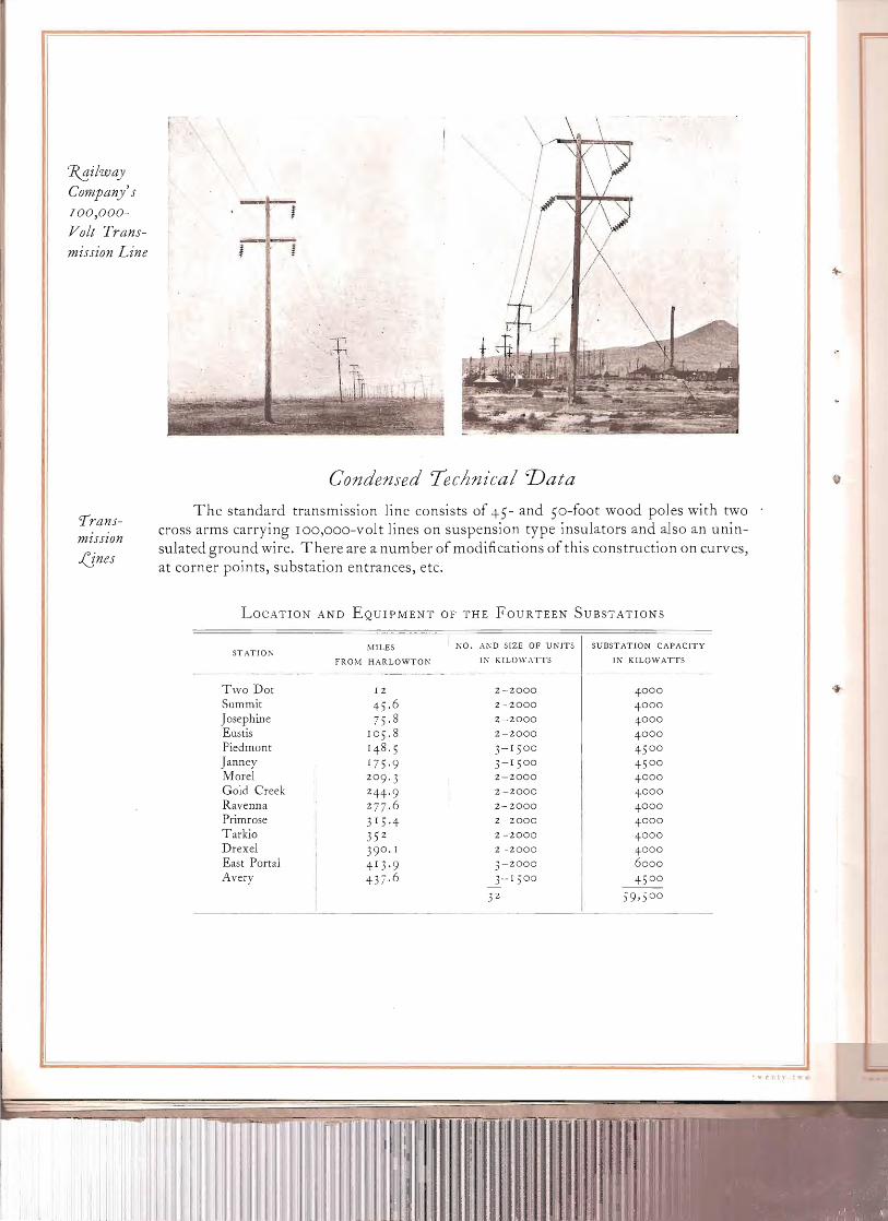
1?.!!,ilway Company's 100,000
Yolt Trans�miHion Line ! !�
Condensed Technical 'Data
The standard transmission line consists of 45- and 50-foot wood poles with two 'I'ranJ cross arms carrying IOO,OOO-volt lines on suspension type insulators and also an uninmzsszon
sulated ground wire. There are a number of modifications of this construction on curves,iJnes at corner points, substation entrances, etc.
LOCATION AND EQUIPMENT OF THE FOURTEEN SUBSTATIONS
KO. AI'D 51ZE OF UNITS SUBSTATION CAPACITYMILES STATJOt\
IN KILOWATTS IN KILOWATTSFROM HARLOWTOK
Two Dot 12 2-·2000 4 000
Summit 45. 6 2-2000 4 000
Josephine 75. 8 2-2000 4 000
Eustis 10 5. 8 2-2000 4 000
Piedmont 148.5 3- 1 5 00 45 00
Janney 175 ·9 3- 1 500 45 00
Morel 2-2000 4 000209.3
Gold Creek 244·9 2-2000 4 000
Ravenna 277. 6 2-2000 4 000
Primrose 3 1 5,4 2-2000 4 000
Tarkio 2 -2000 4 00035 2
Drexel 1 2 -2000 4 000390 .
East Ponal 4 1 3.9 3-2000 6000
Avery 437. 6 3-1 ;00 45 00
J'2 59,5 00
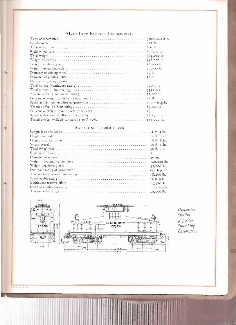
MoUN LI~E FRElGHT LOCOMOTIVES
Type of locomot' ve, . Length overall Tota] wheel base .", .... , .... Rigid wheel base Total weight Vi eight on drivers. Weight per driving axle ' , . Weight per guiding axle ' .. , ... Diameter of driving wheel. . . . Diameter of guiding whee], . . . . . . . . . . . . N umber of driving motors , . Total output (continuous rati..ng) , , .. , Total output (I hour rating) . Tractive efFort (continuous rating) . , , .. , , . .. . .. , . Per cent of weight on drivers (trac. coef.) , ... , . Speed at this tractive efFort at 3°00 vol ts ' . Tractive efFort (I hour rating) . . Per cent of weight upon drivers (trac. coer.) , , ..
Speed at this tractive efFort at 3°00 volts Tractive efFort available for starting 3°% coer. ' .
SWITCHING LOCOMOTIVES
Length inside knuckles Height over cab .. , Height-trolley dO\\'ll Width overall .. Total wheel base . ' , , , Rigid wheel base Diameter of wheels. , , ' Weight-locomotive complete Weight per driving axle One hour rating of locomotive .. Tractive efFort at one hour rating Speed at this rating .. Continuous tracti\'e efFort . Speed at continuous rating ... Tractive efFort 30% .
--�CP",,·----
= " ~=;:~~:;:;;:=l c.M:t~~P"
'10 SO....•..;.
3000 volts doc,� J J 2 ft.� 102 ft. 8 in.� JO ft. 6 in.� 564,000 lb.� 448,000 lb.� 56,000 lb.� 29,000 lb.� 52 in.� 36 in.� 8� 3000 h.p.� 3440 h.p.� 71,000 lb.�
J 5.83 15.75 m.p.h. 85,000 lb.
19 J5.25 m.p.h. 136,000 lb.
41 fi. 5 In.
14 ft. 3 in. 16 ft. 8 in. 10 ft. 1 ill.
30 ft. 4 in. 8 ft.
40 in. 14°,000 lb. 35,000 lb. 542 h.p. 18,400 lb. 12 m.p.h.
13,480 lb. 1J.2 m.p.h. 42,000 lb.
Dimension
Outline
of 7 0 - ton
Switching Locomoti·ve
r
II
CONTACTOIrS
:Ii: I~ 'I I ;;
I~'I' II, ·~II'II'!_II.I,!t'!11
-T f I '--':::::::::::.t=J~, ~I !' ,. • • 'I·~.
T. 1-1 I \ j-; ''::J'-: - I I _" _ -' " ~ I
---rra':- _/o,r,Ok_ ----/O"'6~--- --lONG"----
L-----------------------S6 N
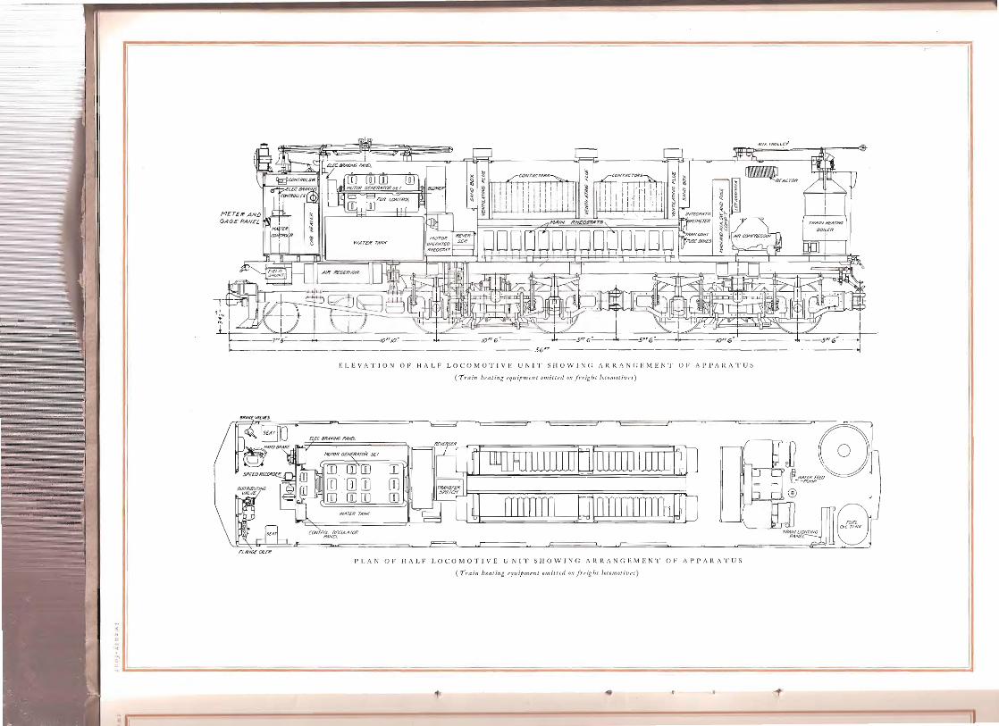
I': I. E V A T JON 0 F H 1\ L FLO COM 0 T I V E U N J T S HOW 1 N (; J\ It It J\ N (; I': MEN T 0 F A P P 1\ R J\ T U S
(Train hflllin[; rr/fdtmnlt omittrd &/1 /I·t:igh, lo(o!1Jotivn)
~l=_== . -,~
m (]Jrn rn ~~8[]] []] []] []]� (]J rn rn rn�
WATCH TANK
TRIlINl.tCIITlNt; P/lN£{
FI..IWU OUR
I~ I. A N 0 F I-I A l~ F J,O COM 0 'r I V E U N J 'f 5 H 0 'N I N (: f\ R It f\ N (; E MEN 'I' 0 F t\ P PAR A 'I' li 5
(Trai" !tr.nling rquipment omitfr.d ()f/ frrighl. locolllotitJf:J)
" ~

I I I I I I I I , I l T I 1 I I I I I I
t1axitnvm Erner enc" Soeed 35/'1. p. If
1\ I ~ I Charac1\ 1\
I 1- I teristic I Maximurr:\OperaiingSpe~Q,3 M. , It. Curves ofI
I I 1\ "'f,,~ c%ain 1:.Jne I ''\T<s>
'oS", 1/ Freight I "'", /100 25 /00000 -0Jcomotives~o--">.� I IFfficiencu w,~ k ears lLru/1. Field
1/80 ;20 80000 1/ l'.� t--
h S~eed -F"
60 15 60000 -(~ f-, ~.\6 I. \ j MaxlmG/m ollowable\it.6 1-1;:::: current with field\\ ~ 4() /0 40000 .II/' hunted 840 f-
aTp"eies { V~L5
,,~~O !!oV I I I -~xim",m allolNoblecu!"...!:!lf!l.S ~£~.vet ...20 20000 fUll !ield position whenOV c,'Y
changing overto oTh"(nye{
I Fie(dl 6fO ,aTPfrrsl
( '((
-I I GE-Z53-AIo 0 ;ZOO 600 800 1000 1200
Amperes
<. I v ~ :> Icu'"c: ~ ~l
.~ <. :.:;~ 'l> v,g� ~k!Q. Charac
~" f.1a~imum emerqency6.oeed. 65MP.H.~ .., -<i teristic ~ I I~ 'l> " Curves ofU 'IZOOO 0
'l> H+-+-I-I-\,'%,--1--J-+++-+-+--+-+-+-+-+-+-J--l,L-' c%ain 1:.Jne<. /!----If---.!-I---f~
Cl. H+-+-I-H~l-J--e-f---.!-I-I-I---f---f-+-+-+--+.4--1-++-+-~ PassengerI-H:+-+\-t---+'<\'(-+-++++-~-+--f--I-I-I-+I/-,4-+++--t-I-H/00 50 /00000 -0Jcomotives f-H--I+++--P\"&~+++-+-+-J--I---J-I-J,t+-+++-+--!-I-+~
90 q.:. r/ic, nc u// Field
80 4-() 80000HH-A-""4-+++-1"L'+-+-I-H-I-!'1/'+++-+I--+--+-+++~ \70
I
60 30 60000H-+-++++-Plh:lh--++/-JUH-++++-H-+--+++-t-H 1
I--Ib'A50
4() 20
'20 /0
/0
o o 800 IZOO /600 2000 .2400
Amperes
I�
OVERHEAD CONSTRUCTION ON TAKGFNT TRACK TR.-\1':SFOR~H:RS AND OIL SWITCHES MOREL SUBSTATION ..
BRACKET CONSTRUCTION ON LIGHT CURVES OVERHEAD C01':STRUCTION AT TEN DEGREE CURVE
twenty-six
'''.
/ /
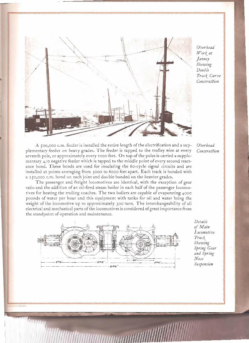
A 500,000 c.m. feeder is installed the entire length of the electrification and a supplementary feeder on heavy grades. The feeder is tapped to the trolley wire at every seventh pole, or approximately every 1000 feet. On top of the poles is carried a supplementary 4/0 negative feeder which is tapped to the middle point of every second reactance bond. These bonds are used for insulating the 60-cycle signal circui ts and are installed at points averaging from 5000 to 6000 feet apart. Each track is bonded with a 250,000 c.m. bond on each joint and double bonded on the heavier grades.
The passenger and freight locomotives are identical, with the exception of gear ratio and the addition of an oil-fired steam boiler in each half of the passenger locomotives for heating the trailing coaches. The two boilers are capable of evaporating 4000 pounds of water per hour and this equipment with tanks for oil and water bring the weight of the locomotive up to approximately 300 tons. The interchangeability of all electrical and mechanical parts of the locomotives is considered ofgreat importance from the standpoint of operation and maintenance.
'-----5""6-'--_---__10""0' _
'.-----------
Overhead
Work.. at Janney Showing Double Track.. Curw Construflion
Overhead Construflion
Details of Main Locomotive Truck.. Showing Spring Gear and Spring Nose Suspension

HydroCleflric Power Station at great Falls
on the , UrCissourz
'RJ..,ver
Four £0,000 j(v-a Waterwheel'Driven generators
in great Falls 'Power Station
t'., ,,:y .• 'b:

E'leBric Power Plants of the rYrfontana Power Co. IN::;TALU':'P
C.-\P.-\CITYCOMPLETED HYDRO-ELECTRIC PLANTS
K.W.
Great Falls, on l\!lissouri River . 60,000 Rainbow Falls, on Missouri River near Great Falls, completed in 1910 . 27,000 Black Eagle Falls, on Missouri River near Great Falls, reconstructed in 19 IJ J,ooo Black Eagle Falls, hydraulic power, 8,000 h.p. Hauser Lake, on Missouri River, northeast of Helena, completed 19 I I .... 18,000 Canyon Ferry, on Missouri River, northeast of Helena, completed in 1898
and enlarged in 190 I . 7,500 .Madison No. I, on Madison River, 60 miles southeast of Butte, completed
in 190 I and remodelled in 19°7 . 2,000 Madison No. '2, on Madison River, 60 miles southeast of Butte, completed
in 1906 . 10,000 Big Hole, on Big Hole River, 22 miles southwest of Butte, completed in
18 98 . J,ooo Livingston, on Yellowstone River, completed in 1906 and enlarged in 19°8 . 1,5°0 Billings NO.1, on Yellowstone River, completed in 19°7 . 1,080 Lewistown, on Spring Creek, completed in 1906 and remodelled in I 9IJ .. +5° Thompson Falls, on Clark's Fork of Columbia River . 20,000
I5J,5Jo STEAM PLANTS
Butte, completed in 1907 : .. 5,000 Billings, completed in 19°6 . . . . . . . . . . . . . . . . . . . . . . . . . . . . . . . . 560 Conrad, com pJeted in 19 10 . . . . . . . . . . . . . . . . . . . . . . . . . . . . . . . . 110 Phoenix, in Butte, completed in 1895 . .. .. 250
T'otal� .
HYDRO-ELECTRIC POWERS IN COURSE OF DEVELOPMENT C.-\P.\CITY
AND DEFINITELY PROJECTED K.W.
Thompson Falls, on Clark's Fork of Columbia River, additional units to be installed in 1917 . 10,000
H?lter, on Missouri River near Helena, under construction, to be completed In 1917 . 4°,000
Total . 5°,000
HYDRO-ELECTRIC POWER SITES UNDEVELOPED
Site "C" at Great Falls, on l\!lissouri River, between Rainbow and Great Falls 28,500 Below Great Falls, on Missouri River . 28,500 On Missouri River about JO miles northwest of Missoula . IJ,500
Madison No. J, on Madison River . 18,500 Black Eagle Plant, reconstruction . . . . . . . . . . . . . . . . .. . . 10,000 Snake River Falls, on Henry's Fork of Snake River, 20 miles north of St.
Anthon:"� Idaho . 22,5°0 Total . 12 I ,500
enty-nine

SUMMARY
Completed hydro-electric and steam plants Hydro-electric powers in course of developmHydro-electric power sites undeveloped
Total .
ent. 159,+5°
5°,000 J 2 J ,5°° 33°,95°
SL'MM.~RY OF TRANSMISSION LINES IN SERVICE ].4.:"TARY 1,1916
Steel tower lines, 100,000 volts . . . . . . . . . . . . . . . . . . . .. 305 miles� Steel to\ver lines, 5°,000 volts . . . . . . . . . . . . . . . . . . . . . . . . . . . . . . . . . . 35 miles� Pole lines, pin type, I 1,000 to 60,000 volts. . . . . . . . . . . . . . . . . .. 635 miles� Pole lines, sllspension insulator type, 5°,000 to 100,000 volts. . . . 512 miles� Bridge type, JOO,OOO volts. . . . . . . . . . . . . . . . . . . . . . . . . . . . . . . . .. 3+1 miles�
Total. . . . . . . . . . . . . . . . . . . . . . . . . . . . . . . . . . . . . . . 1,828 miles�
These water power plants are so located at widely separated points that there is little probability of an interruption of the supply.
Available capacity of storage reservoirs in service is ++7,J 50 acre feet, of which the largest, the Hebgen reservoir on Nladison River, contributes 325,000 acre teet.' There is a further undeveloped capacity of 78,500 acre feet.
Type of Mallet engine Replaced by Cleflric iJcomotives
t h i rt v

"II