ELECTRICITY KIT - for DC and AC
55
INSTRUCTION SHEET INDUSTRIAL EQUIPMENT & CONTROL PTY.LTD. 61-65 McClure St. Thornbury. 3071 Melbourne. Australia Tel: 61 (0)3 9497 2555 Fax: 61 (0)3 9497 2166 e m 1 7 6 3 - 0 0 1 e x p k i t A L 1 2 - S e p - 1 4 1 ELECTRICITY KIT - for DC and AC Cat: EM1763-001 KIT LAYOUT
Transcript of ELECTRICITY KIT - for DC and AC

INSTRUCTION SHEET
I N D U S T R I A L E Q U I P M E N T & C O N T R O L P T Y . L T D .6 1 - 6 5 M c C l u r e S t . T h o r n b u r y . 3 0 7 1 M e l b o u r n e . A u s t r a l i a
T e l : 6 1 ( 0 ) 3 9 4 9 7 2 5 5 5 F a x : 6 1 ( 0 ) 3 9 4 9 7 2 1 6 6e m 1 7 6 3 - 0 0 1 e x p k i t A L 1 2 - S e p - 1 4
1
ELECTRICITY KIT - for DC and AC
Cat: EM1763-001 KIT LAYOUT

INSTRUCTION SHEET
I N D U S T R I A L E Q U I P M E N T & C O N T R O L P T Y . L T D .6 1 - 6 5 M c C l u r e S t . T h o r n b u r y . 3 0 7 1 M e l b o u r n e . A u s t r a l i a
T e l : 6 1 ( 0 ) 3 9 4 9 7 2 5 5 5 F a x : 6 1 ( 0 ) 3 9 4 9 7 2 1 6 6e m 1 7 6 3 - 0 0 1 e x p k i t A L 1 2 - S e p - 1 4
2
GENERAL DESCRIPTION:
This kit is designed to perform important basic experiments with electricity. To study electric circuits,switches, lamps, voltage, current, resistance and Ohm’s law. Also series and parallel circuits,heating effect of electric current, fuses, conduction through liquids, magnetism, electromagnetism,inductance and capacitance.
The kit permits also the study of the AC form of electricity, electromagnetic induction, laminatedcores, transformers, inductors, eddy current losses and heating, impedance and reactance.
DESIGN FEATURES OF THE KIT:
• The ventilated housings for the components are transparent so the components are easilyvisible to the students.
• The front labels are bright, simple and easy to read.
• Special labels on the sides of the housings allow identification of each component when theyare stored edgeways.
• All connections are by printed circuits for extreme reliability.
• All connections are by strong 4mm banana plugs.
• All cables have banana plugs moulded to the cables for maximum strength and reliability.
• The meters are digital and are complete with 9V batteries fitted. The ranges are both AC andDC Volts and Amps together good Ohms ranges. Capacitance up to 20uF can be measureddirectly.
• Small parts are housed in strong plastic containers with labels to show the contents.
• Reels of copper and resistance wires are provided for basic experiments and the study offuses.
• Both 2.5V and 12V lamps are provided for various experiments.
• For safety, basic experiments are performed by ‘D’ sized dry cells and more advancedexperiments and AC experiments use the compact power supply provided.
• The laminated ‘U’ and ‘I’ core is strong and compact for all induction and transformerexperiments.
THE POWER SOURCES:
The kit has both holders for ‘D’ cells and a low voltage DC/AC power supply.
For many basic experiments it is much safer to run from dry cells so the power source cannot supplytoo much current. This is to avoid damage to lamps and to avoid sudden heating of wires or damageto components.
It is suggested that after the students gain some knowledge and understanding by using dry cells, thehigher current power supply can be introduced with care and supervision.
The power supply is excellent for many experiments in heating or for electromagnets and anyexperiment where extra power is required. The power supply is essential for all AC experiments withinduction and transformers etc..
The Power Supply has the mains power switch on the rear and green indicator lamp on the frontpanel. If the power supply is overloaded, the lamp glows red to indicate overload. Automatically, theoverload will reset and the lamp will turn green when the output is restored.

INSTRUCTION SHEET
I N D U S T R I A L E Q U I P M E N T & C O N T R O L P T Y . L T D .6 1 - 6 5 M c C l u r e S t . T h o r n b u r y . 3 0 7 1 M e l b o u r n e . A u s t r a l i a
T e l : 6 1 ( 0 ) 3 9 4 9 7 2 5 5 5 F a x : 6 1 ( 0 ) 3 9 4 9 7 2 1 6 6e m 1 7 6 3 - 0 0 1 e x p k i t A L 1 2 - S e p - 1 4
3
KIT CONTENTS: 12 transparent housings for components:
• 1x Potentiometer, 50 Ohms, 3 Watt, wire wound, in housing.
• 1x Resistor 50 Ohms, in housing.
• 1x Resistor 100 Ohms, in housing.
• 1x Resistor 500 Ohms, in housing.
• 2x Capacitors 5uF (+/-10%) in housing
• 1x Capacitor 10uF (+/-10%) in housing.
• 3x Lamp holder, in housing.
• 1x Switch, single pole, one way, in housing.
• 1x Switch, single pole, two way, in housing.
• 1x Connector box (for alligator clips to hold wires)
• 1x Power Supply. Input: 220/240V.AC. Output: Switched at 2, 4, 6, 8, 10, 12V output,both AC and DC at 5 amps total load. DC is full wave, unfiltered. Automatically resettingoverload with indication. With removable mains cable.
• 1x reserved space for Digital Signal Generator. Input: 220/240V.AC. Output: Sine, Square,Triangle & Sawtooth waveforms. 5V.RMS or 15V p/p, Frequency from 0.1Hz to 100 kHz.Output current 1 amp. Automatic overload protection. With removable mains cable.This instrument is supplied in more advanced kits.
• 1x reserved space for Hand driven AC/DC Motor Generator. A rugged and compactinstrument that can be used with its permanent magnet or can be slid on to the “U” core toprovide a variable AC or DC field. This instrument is supplied in more advanced kits.
• 1x Set of 12x cables with moulded and stackable 4mm Banana Plugs.
• 1x Set of “U” and “I” core for transformer study, with elastic bands.
• 4x Coils to fit the “U” & “I” core. 1x 300T, 2x 600T, 1x 1,200T.
• 1x Set/3 plain iron cores (1x long, 2x short) for magnetic experiments.
• 1x Aluminium Disc & Axle for eddy current brake experiment.
• 3x Multi-meters, digital, with 4mm banana plug cables.
• 2x Cell holders for ‘D’ cell.
• 2x Plastic supports for holding iron cores to “U” core.
• 1x Pair bar ‘Alnico’ magnets (75mm long x12mm x8mm).
• 1x Set/3 magnetic field demonstrators suitable for bench work or for o/head projector:
Circular coil Straight conductor Solenoid coil. Iron Filings in a shaker.
1), 2), 3) small screw-top vials:
• 10x Plotting Compasses.
• 10x MES lamps for 2.5 Volts 200mA 10x MES lamps for 12 Volts 100mA.
• 1x pair of strong “alnico” bar magnets.
4) 3x Rolls of wire & capacitor measuring wires:
• 1x Roll: 100m Copper wire, 0.2mm diameter
• 1x Roll: 100m Resistance wire, “Constantan” 0.2mm diameter
• 1x Roll: 50m 1 Amp fuse wire, 0.05mm diameter.
• 4x Wires for fitting into capacitor sockets of multimeters for connection.
• 2x Paper clips for connections etc.

INSTRUCTION SHEET
I N D U S T R I A L E Q U I P M E N T & C O N T R O L P T Y . L T D .6 1 - 6 5 M c C l u r e S t . T h o r n b u r y . 3 0 7 1 M e l b o u r n e . A u s t r a l i a
T e l : 6 1 ( 0 ) 3 9 4 9 7 2 5 5 5 F a x : 6 1 ( 0 ) 3 9 4 9 7 2 1 6 6e m 1 7 6 3 - 0 0 1 e x p k i t A L 1 2 - S e p - 1 4
4
5) Various items:
• 4x Alligator Clips, plain. Can fit to 4mm banana plugs.
• 4x Alligator Clips, fitted with 4mm banana plugs (for holding all wires).
• 2x electrode plates. 1x Copper, 1x Zinc, size 70 x 20mm.
• 2x conductivity plates, stainless steel. Size 70 x 20mm.
• 1x Ring for ‘Thompson’s Ring’ experiment.
• 1x Compass for determining North/South Pole of magnetic fields.

INSTRUCTION SHEET
I N D U S T R I A L E Q U I P M E N T & C O N T R O L P T Y . L T D .6 1 - 6 5 M c C l u r e S t . T h o r n b u r y . 3 0 7 1 M e l b o u r n e . A u s t r a l i a
T e l : 6 1 ( 0 ) 3 9 4 9 7 2 5 5 5 F a x : 6 1 ( 0 ) 3 9 4 9 7 2 1 6 6e m 1 7 6 3 - 0 0 1 e x p k i t A L 1 2 - S e p - 1 4
5
GLOSSARY OF TERMS USED IN THIS MANUAL:
AC: Means Alternating Current. This is current that flows both forward and backwards following asine wave waveform. AC does not have a + and - polarity so red and black terminal and wire coloursare usually not used.
AMPS: This is the name or unit given to the flow of electricity or electrical current. If one Volt ofpotential is applied to one Ohm of resistance, then one Amp of current flows. If currents are small,the unit can be milliamps or ‘mA’ (one thousandth of an amp). If currents are very small, the unit canbe microamps or ‘uA’ (one millionth of an amp).
BOOST: Term used to indicate that two separate windings on a transformer are connected so thatone voltage adds to the other.
BUCK: Term used to indicate that two separate windings on a transformer are connected so that onevoltage subtracts from the other.
CAPACITOR: A capacitor is a device that can store electric charge (something like a battery). Theenergy is stored as voltage is applied and current flows into it until it is ‘charged’. At a later time, thisenergy can be released, or ‘discharged’ again to perform a function. These are commonly used incircuits that rectify AC to DC to try to make rectified DC smoother. When the AC waveform falls tozero, the energy stored in the capacitor is discharged to try to fill the gaps in the AC waveform. As theAC waveform rises again, the capacitor is re-charged. This occurs 100 times per second and whenused in this manner, they are called ‘filter capacitors’. Large filter capacitors are polarised and aredesigned to be connected only to a DC voltage source. They are called ‘electrolytic’ capacitors.CAUTION::: If electrolytic capacitors are connected to AC or if they are connected backwards to theDC voltage, they get hot and burst with a loud ‘bang’. Some capacitors are designed for AC butthese are not electrolytic and are much smaller capacitance. There are many types of capacitors forvarious voltages and uses.
CHOKE: This is an AC device and is sometimes called an ‘Inductor’. It is an iron core with only onecoil fitted. The magnetic field in the iron caused by the current through the coil also cuts the turns ofwire in the same coil and causes a reverse voltage in the winding that opposes the applied voltage.This tries to stop the flow of current through the coil. The AC current flowing through any coil withoutiron core is greatly reduced when an iron core is fitted.
CORE: Means the iron shape that is used to couple the magnetic field between two or more coils. Amagnetic field can exist much more easily in an iron core than it can in air. When an iron core is usedinside the coils, the induction effect is much more efficient. See ‘Reluctance’.
CURRENT: This is the conventional flow of electricity through a conductor. It is caused by an EMFor voltage causing electrons to flow in a conductor if a circuit is closed. In DC circuits, the currentflows in a conductor ‘in phase’ (see glossary) with the voltage. In AC circuits this is not always thecase, but this phenomenon is reserved for more advanced AC studies.
DC: Means Direct Current. This is current that flows in one direction only. It might be a smooth,non-varying current from a battery, or it might be a pulsating current which is obtained when AC isrectified to DC. The AC sine wave is converted by the rectifier to flow in one direction, but rises andfalls 100 times per second from zero to maximum in the shape of half of a sine wave. DC has apolarity and normally red means positive and black means negative. Current flows in a DC circuit frompositive to negative.
EMF: Means Electro Motive Force. This is the voltage generated in a conductor when it moveswithin a magnetic field. Voltage is like the pressure of electricity and, when the circuit is closed, acurrent is forced through the conductors because of the presence of an EMF. The amount of currentflowing depends on the magnitude of the EMF and the resistance of the circuit (Ohm’s Law).
FIELD: This is a general name given to magnetic lines of force either in an iron core or in air.

INSTRUCTION SHEET
I N D U S T R I A L E Q U I P M E N T & C O N T R O L P T Y . L T D .6 1 - 6 5 M c C l u r e S t . T h o r n b u r y . 3 0 7 1 M e l b o u r n e . A u s t r a l i a
T e l : 6 1 ( 0 ) 3 9 4 9 7 2 5 5 5 F a x : 6 1 ( 0 ) 3 9 4 9 7 2 1 6 6e m 1 7 6 3 - 0 0 1 e x p k i t A L 1 2 - S e p - 1 4
6
FILTER: When AC voltage is rectified to create DC, the DC is not smooth like a battery. It followsthe AC sine wave shape and, although it does not reverse direction, it rises from zero volts up to apeak and falls again 100 times per second (full wave rectification) or 50 times per second (half waverectification). A filter, which is usually a large value capacitor connected across the DC, charges up tothe peak voltage and discharges into the load to try to level out the humps and make it closer to asmooth DC. The effect is best seen on an oscilloscope.
FLUX: Is a general term meaning the magnetic field present usually in an iron core.
FREQUENCY: This is the number of times per second that the AC wave passes through one fullcycle of rising from zero to maximum, then falling through zero to minimum and then rising to zeroagain. The unit is Hertz. Normal mains power in Australia has a frequency of 50Hz. Other countriessuch as USA and Canada (and many others) use a 60Hz power system.
IMPEDANCE: In the world of DC, resistance (ohms) is the factor that controls the current in a circuit.In the world of AC, there is a mixture of both Resistance and Reactance which alter the flow of currentthrough an AC circuit. The term Impedance means the combination of these two phenomena. Theterm ‘Low Impedance’ means a circuit that has only small total resistive effect to an AC current flow.
INDUCTANCE: This is the measurement of a coil’s inductive effect in Henrys. Inductance dependson the number of turns in the coil and the amount of iron in the core. Coils of low inductance (microHenrys) are used in radio sets for tuning stations and coils of larger inductance (milli Henrys orHenrys) are used as Chokes for power supply filters or high power oscillators and special equipment.
INDUCTION: Means the inducing of a voltage in a coil of wire by the application of a magnetic fieldfrom either a magnet or another coil of wire. The coils of wire are usually not electrically connected.
INDUCTOR: An inductor is a coil of many turns of wire mounted on an iron core (see Choke).
LAMINATIONS: Iron cores in an AC device are made from thin strips of iron instead of from solidblocks of iron. These thin strips are called laminations and are insulated electrically so current cannotflow from one to another. This is to reduce or eliminate wasteful and unwanted circulating currents inthe iron.
LEAKAGE: This is stray magnetic field that appears outside the iron core. Any field leaking outsidethe iron core cannot be used by the transformer in driving the secondary coil. Transformer designtries to keep magnetic leakage to a minimum.
LOAD: The term ‘load’ is used for any circuit that draws power from a power source. If a resistor isconnected to a battery so that current flows, the resistor can be called the ‘battery’s load’. The currentdrawn by the resistor can also be called the ‘load’ on the power source.
LOSSES: This is the name given to energy provided by the Primary coil to the system but notavailable as usable energy from the secondary coils. Transformer losses include:
• The energy required in magnetising and de-magnetising and reversing the magnetisation inthe core 100 times per second. Special iron used for transformers has low losses.
• Resistance in the copper wire of the windings causing voltage loss and heat generated.
• Circulating currents in the iron core causing heating of the iron.
• Loss of magnetic field (leakage) into the air from the iron core.
MAGNETISING CURRENT: This is the current drawn from the power source by the primary coilrequired to magnetise the iron core and to overcome leakage and losses. Transformer design tries tokeep the magnetising current as small as possible because it is wasted energy from the power sourceand causes unwanted heating in the primary coil.
PARALLEL CONNECTION: When two or more devices are connected so that the current dividesand flows through side-by-side paths, they are said to be connected ‘in parallel’. The total currentfrom the source is the sum of the parallel currents.

INSTRUCTION SHEET
I N D U S T R I A L E Q U I P M E N T & C O N T R O L P T Y . L T D .6 1 - 6 5 M c C l u r e S t . T h o r n b u r y . 3 0 7 1 M e l b o u r n e . A u s t r a l i a
T e l : 6 1 ( 0 ) 3 9 4 9 7 2 5 5 5 F a x : 6 1 ( 0 ) 3 9 4 9 7 2 1 6 6e m 1 7 6 3 - 0 0 1 e x p k i t A L 1 2 - S e p - 1 4
7
PEAK VOLTAGE: Unfiltered DC voltage is a sine wave shape that rises to a peak value and falls tozero volts 100 times per second. When a DC voltmeter meter is placed on the DC, it shows theaverage DC voltage (not the peak voltage). If a capacitor is placed on the output when there is noload connected to the power supply, it will charge to the peak value which is the highest point of thesine wave. The voltmeter will show this higher peak voltage (average x approx.1.4). When a load isplaced on the power supply, the capacitor will discharge this extra energy into the load as the sinewave falls 100 times per second and the voltmeter will then show the average voltage again. But thiswill be a higher average than before because the capacitor adds extra energy to the load.
PHASE: If you raise both arms and lower them together, they are ‘in-phase’. If one arm rises as theother arm falls, they are ‘out of phase’. The timing relationship of two voltages or two currents or avoltage compared to a current is called the ‘phase relationship’. In the world of DC, currents andvoltages are usually ‘in phase’. This is not always the case in the world of AC.
As an AC voltage rises in a coil with an iron core, the current through the coil rises slightly later thanthe voltage. Therefore the magnetic field also rises slightly later than the voltage. The voltageinduced in a secondary coil therefore appears at a different instant when compared to the appliedvoltage. Look at these voltages on a double beam oscilloscope. If a secondary coil is wound thesame direction (clockwise or anti-clockwise) as another secondary coil, the AC voltage on these twocoils will be rising and falling at exactly the same time. This means they are ‘in phase’. If they areconnected in series, their voltages will add (see ‘boost’ in the glossary). If one coil is wound in theopposite direction, they will be ‘out of phase’ and their voltages will subtract (see ‘buck’ in theglossary). Phase angle is from 0 to 360 degrees. The term ‘in phase’ means a shift of zero degreesin phase. ‘out of phase’ means a shift of 180 degrees in phase.
PRIMARY; The name given to the transformer winding that is connected to the power source. Itprovides the energy to both magnetise the iron core and to transfer to the secondary winding(s).
REACTANCE: The world of DC has Resistance (Ohms) that controls the flow of DC current in acircuit and generates heat (Watts). In the world of AC, resistance exists but, in addition to resistance,AC circuits have Reactance. It behaves like resistance but does not generate heat. Reactancedepends on the Inductance (Henrys) of a coil or Capacitance (microfarads) of a capacitor and theFrequency (Hertz) of the AC current flowing through it.
RECTIFICATION: AC can be changed to DC by ‘rectification’. If a single diode is used, only one halfof the AC waveform passes through the diode as DC and the voltage appears as 50 humps persecond. If 4 diodes are connected in a ‘bridge’ configuration ‘full wave’ rectifier, both halves of the ACwaveform are rectified and the DC appears as 100 humps per second. If a transformer winding has a‘centre tapping’, only 2 diodes are required to create ‘full wave’ rectification. Rectification is reservedfor electronic study and is not covered in this booklet.
RELUCTANCE: The ability of a material to support a magnetic field is called the ‘reluctance’ of thematerial. Air has a very high reluctance and iron has a low reluctance. The special laminated ironused to make transformer cores usually has a very low reluctance.
RESISTANCE: Means the ease or difficulty that electrons have in flowing through a circuit. Glassdoes not conduct electricity, so it can be said that it has an extremely high resistance. Metals alloweasy flow of electrons, and can be said to have a very low resistance. Every material has resistancevalue in OHMS. ‘Kilohms’ means thousands of ohms. ‘Megohms’ means millions of ohms.
Ohm’s law: 1 volt EMF causes 1 AMP of current to flow through 1 OHM of resistance.
ROTOR: The rotor of a motor is the part that rotates
SECONDARY: The name given to winding(s) of a transformer that are not the ‘Primary’ winding.
SERIES CONNECTION: When two or more devices are connected so the current must pass from theend of one into the beginning of the next so that the same current flows through all of them, they aresaid to be connected ‘in series.

INSTRUCTION SHEET
I N D U S T R I A L E Q U I P M E N T & C O N T R O L P T Y . L T D .6 1 - 6 5 M c C l u r e S t . T h o r n b u r y . 3 0 7 1 M e l b o u r n e . A u s t r a l i a
T e l : 6 1 ( 0 ) 3 9 4 9 7 2 5 5 5 F a x : 6 1 ( 0 ) 3 9 4 9 7 2 1 6 6e m 1 7 6 3 - 0 0 1 e x p k i t A L 1 2 - S e p - 1 4
8
STATOR: The stator of a motor is the part that does not rotate.
TAPPING: If a coil is wound part way (say 20 turns) and the wire is then looped from the bobbin to aconnection point and then returned to the coil and the coil wound further, the coil is said to have atapping. Transformer coils can have as many tappings as desired to provide many voltages from theone coil. If two coils of say 50 turns are connected in series, this is the same effect as one 100 turncoil tapped at the mid point.
TRANSFORMER: This is a device where two or more coils of wire are coupled by an iron core sothat the magnetic field in the iron created by one of the coils (the primary coil) induces a voltage in theother coils. The coils are not normally electrically connected to each other. Depending on the numberof turns of wire on the coils, the voltage applied to the primary coil can be changed or transformed to adifferent voltage on the secondary coil(s). The thickness of the wire forming the coils has no effect onthe voltages created. The wire thickness should be calculated to suit the current flows in and out ofthe transformer to avoid overheating of the wire.
VOLTAGE: This is the electrical ‘pressure’ that is created in a conductor when a conductor movesrelative to a magnetic field to cut the lines of magnetic force. The voltage cannot cause current to flowuntil the circuit is closed. The voltage is dependent on the strength of the field and the speed ofmotion of the conductor. Voltage can be created also chemically as in a battery or by heat or light orby electric charge as in static electricity, lightning and similar. To understand voltage, it can beconsidered to be similar to pressure of water in a pipe. Pressure of water is present in a pipe but theflow of water (like electrical current) cannot occur until a circuit is made with pipes (like electrical wires)and until the tap is opened (like an electrical switch turned on).
VOLTS: This is the name or unit given to the potential of electricity or electrical pressure. If oneVolt of potential is applied to one Ohm of resistance, then one Amp of current flows. If voltages aresmall, the unit can be millivolts or ‘mV’ (one thousandth of a volt). If voltages are very small, the unitcan be microvolts or ‘uV’ (one millionth of a volt).
WATTS: When a voltage causes a current to flow through a resistance, heat is generated in theresistance. The unit of the power generated is Watts. If powers are small, the unit can be milliwattsor ‘mW’ (one thousandth of a watt). If powers are very small, the unit can be microwatts or ‘uW’ (onemillionth of a watt). For a DC circuit, Volts x Amps = Watts. For AC circuits it is more complicatedand this is reserved for later study.
INSTRUCTION SHEET
I N D U S T R I A L E Q U I P M E N T & C O N T R O L P T Y . L T D .6 1 - 6 5 M c C l u r e S t . T h o r n b u r y . 3 0 7 1 M e l b o u r n e . A u s t r a l i a
T e l : 6 1 ( 0 ) 3 9 4 9 7 2 5 5 5 F a x : 6 1 ( 0 ) 3 9 4 9 7 2 1 6 6e m 1 7 6 3 - 0 0 1 e x p k i t A L 1 2 - S e p - 1 4
9
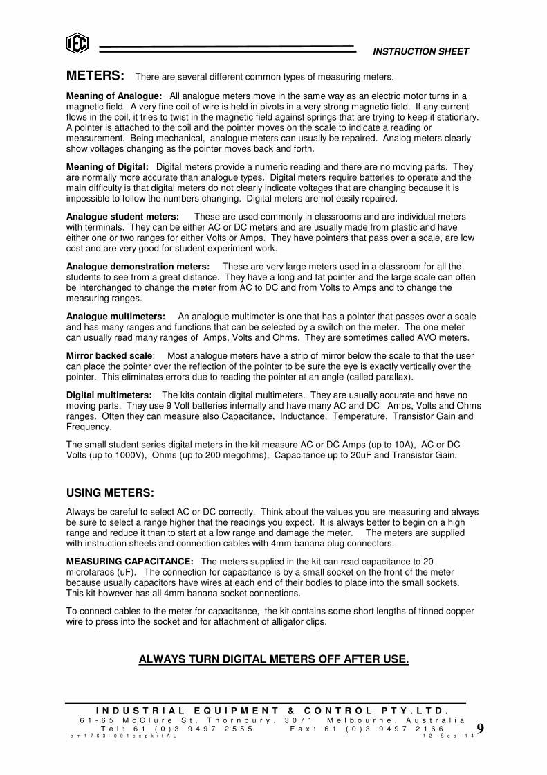
METERS: There are several different common types of measuring meters.
Meaning of Analogue: All analogue meters move in the same way as an electric motor turns in amagnetic field. A very fine coil of wire is held in pivots in a very strong magnetic field. If any currentflows in the coil, it tries to twist in the magnetic field against springs that are trying to keep it stationary.A pointer is attached to the coil and the pointer moves on the scale to indicate a reading ormeasurement. Being mechanical, analogue meters can usually be repaired. Analog meters clearlyshow voltages changing as the pointer moves back and forth.
Meaning of Digital: Digital meters provide a numeric reading and there are no moving parts. Theyare normally more accurate than analogue types. Digital meters require batteries to operate and themain difficulty is that digital meters do not clearly indicate voltages that are changing because it isimpossible to follow the numbers changing. Digital meters are not easily repaired.
Analogue student meters: These are used commonly in classrooms and are individual meterswith terminals. They can be either AC or DC meters and are usually made from plastic and haveeither one or two ranges for either Volts or Amps. They have pointers that pass over a scale, are lowcost and are very good for student experiment work.
Analogue demonstration meters: These are very large meters used in a classroom for all thestudents to see from a great distance. They have a long and fat pointer and the large scale can oftenbe interchanged to change the meter from AC to DC and from Volts to Amps and to change themeasuring ranges.
Analogue multimeters: An analogue multimeter is one that has a pointer that passes over a scaleand has many ranges and functions that can be selected by a switch on the meter. The one metercan usually read many ranges of Amps, Volts and Ohms. They are sometimes called AVO meters.
Mirror backed scale: Most analogue meters have a strip of mirror below the scale to that the usercan place the pointer over the reflection of the pointer to be sure the eye is exactly vertically over thepointer. This eliminates errors due to reading the pointer at an angle (called parallax).
Digital multimeters: The kits contain digital multimeters. They are usually accurate and have nomoving parts. They use 9 Volt batteries internally and have many AC and DC Amps, Volts and Ohmsranges. Often they can measure also Capacitance, Inductance, Temperature, Transistor Gain andFrequency.
The small student series digital meters in the kit measure AC or DC Amps (up to 10A), AC or DCVolts (up to 1000V), Ohms (up to 200 megohms), Capacitance up to 20uF and Transistor Gain.
USING METERS:
Always be careful to select AC or DC correctly. Think about the values you are measuring and alwaysbe sure to select a range higher that the readings you expect. It is always better to begin on a highrange and reduce it than to start at a low range and damage the meter. The meters are suppliedwith instruction sheets and connection cables with 4mm banana plug connectors.
MEASURING CAPACITANCE: The meters supplied in the kit can read capacitance to 20microfarads (uF). The connection for capacitance is by a small socket on the front of the meterbecause usually capacitors have wires at each end of their bodies to place into the small sockets.This kit however has all 4mm banana socket connections.
To connect cables to the meter for capacitance, the kit contains some short lengths of tinned copperwire to press into the socket and for attachment of alligator clips.
ALWAYS TURN DIGITAL METERS OFF AFTER USE.
INSTRUCTION SHEET
I N D U S T R I A L E Q U I P M E N T & C O N T R O L P T Y . L T D .6 1 - 6 5 M c C l u r e S t . T h o r n b u r y . 3 0 7 1 M e l b o u r n e . A u s t r a l i a
T e l : 6 1 ( 0 ) 3 9 4 9 7 2 5 5 5 F a x : 6 1 ( 0 ) 3 9 4 9 7 2 1 6 6e m 1 7 6 3 - 0 0 1 e x p k i t A L 1 2 - S e p - 1 4
1 0
Experiment list: for D.C. for A.C.
1 Turn lamp on and off 41 AC current in capacitors. Reactance.
2 Select between 2 lamps 42 AC current in inductors. Reactance, Impedance
3 Operate a lamp from 2 switches 43 Magnetising fields, theory & concepts
4 Voltage measurement, 1x cell 44 Field around a straight conductor
5 Voltage measurement, 2x cells in series 45 Field around a single coil
6 Voltage measurement, 2x cells in parallel 46 Field in a solenoid
7 Current measurement using ammeter. 47 Theory of induction. Moving coil, stationary field
8 Conductors and non-conductors 48 Stationary coil, moving field.
9 Can liquids carry current ? 49 Use a coil to provide the field
10 Smaller currents through liquids 50 Using AC instead of DC
11 Ohm’s Law, using wires (part 1) 51 Transformers & coils
12 Ohm’s Law, using wires (part 2) 52 Coil direction. Clockwise & Anticlockwise
13 Ohm’s Law, using wires (part 3) 53 Choosing meters for measurement
14 Ohm’s Law, using wires (part 4) 54 Why do transformers use AC ?
15 Ohm’s Law, using wires (part 5) 55 Laminated iron cores
16 Using Ohm’s law. Resistors in series 56 Magnetising current
17 Is a lamp a resistor ? 57 Useful eddy currents
18 Connecting 2 lamps in series. Shortcircuit.
58 The transformer
1989
Connecting 2 resistors in series 59 Leakage in iron cores
20 Voltage divider using resistors 60 Measure DC magnetising current
21 Connecting 2 lamps in parallel 61 Measure AC magnetising current
22 Connecting 2 resistors in parallel 62 Connect coils in different ways. Buck and Boost
23 Connecting resistors in series/parallel 63 Thompson’s ring experiment
24 Internal resistance of a cell 64
25 Why use 2 cells in parallel ? 65
26 Making a Voltage Divider using wire 66
27 Using a potentiometer (voltage divider) 67
28 Making a Rheostat from a potentiometer 68
29 Creating heat energy from electricity 69
30 Creating light energy from electricity 70
31 Making a fuse 71
3233
Power in an electrical circuit 72
33 Making a heater for water 73
34 Work performed by an electric current 74
35 Voltage created by chemistry 75
36 Capacitors charge and voltage 76
37 Charge one capacitor from another 77
38 78
3940
79
40 80

INSTRUCTION SHEET
I N D U S T R I A L E Q U I P M E N T & C O N T R O L P T Y . L T D .6 1 - 6 5 M c C l u r e S t . T h o r n b u r y . 3 0 7 1 M e l b o u r n e . A u s t r a l i a
T e l : 6 1 ( 0 ) 3 9 4 9 7 2 5 5 5 F a x : 6 1 ( 0 ) 3 9 4 9 7 2 1 6 6e m 1 7 6 3 - 0 0 1 e x p k i t A L 1 2 - S e p - 1 4
1 1
D.C. EXPERIMENTS. using dry cells and Power Supply:
Read the Glossary to find the meaning of “DC”.
1) Electric circuit to turn 1 lamp on and off.
Equipment required:
• 1x ‘D’ size cell in holder
• 1x switch, single pole, 1 way
• 1x lamp holder fitted with 2.5V lamp
• 2x alligator clips to fit to banana plugs
• 3x cables with banana plugs
Fit alligator clips to 2 cables
Connect the circuit as shown by pushing the cable banana plugs into the sockets provided on eachcomponent. Use alligator clips to connect the cables to the cell holder. The cell provides a voltage,when a circuit is connected to a voltage, a current flows. When the switch is turned ON, socket 1connects to socket 2, current flows from the positive end of the cell, through the switch connections,through the lamp and back to the negative end of the cell. The lamp will come ON. The arrow onthe circuit shows the direction of current flow.
Turn the lamp OFF and disconnect the cell and reverse the direction. This time, the current will flowthe opposite way around the circuit. The lamp comes ON and the lamp works the same if the currentflows either direction.
2) Electric circuit to select between two lamps.
Equipment required:
• 1x ‘D’ size cell in holder
• 1x switch, single pole, 1 way
• 1x switch, single pole, 2 way
• 2x lamp holders fitted with 2.5V lamp
• 2x alligator clips to fit to banana plugs
• 6x cables with banana plugs
Fit alligator clips to 2 cables
Connect the circuit as shown by pushing the cable banana plugs into the sockets provided on eachcomponent. When the 1 way switch is ON, sockets 1 & 2 are connected to carry current to the lamps.The 2 way switch has 3 sockets and this switch can switch two different ways. One way it joins socket1 to socket 2 and the other way it joins socket 1 to socket 3. This switch can select which lamp tooperate.
EXERCISE: repeat experiment 1) again, but use the 2 way switch. First connect sockets 1 and 2 inthe circuit. Then try again using sockets 1 and 3.
What happens if you use sockets 2 and 3 ? Explain why ?

INSTRUCTION SHEET
I N D U S T R I A L E Q U I P M E N T & C O N T R O L P T Y . L T D .6 1 - 6 5 M c C l u r e S t . T h o r n b u r y . 3 0 7 1 M e l b o u r n e . A u s t r a l i a
T e l : 6 1 ( 0 ) 3 9 4 9 7 2 5 5 5 F a x : 6 1 ( 0 ) 3 9 4 9 7 2 1 6 6e m 1 7 6 3 - 0 0 1 e x p k i t A L 1 2 - S e p - 1 4
1 2
3) Electric circuit to light a lamp from two switches (2 way switching).
Equipment required:
• 1x ‘D’ size cell in holder
• 2x switch, single pole, 2 way
There is only one 2 way switch in each kit,
so borrow another one from another kit
• 1x lamp holder fitted with 2.5V lamp
• 2x alligator clips to fit to banana plugs
• 5x cables with banana plugs
Fit alligator clips to 2 cables
Connect the circuit as shown by pushing the cable banana plugs into the sockets provided on eachcomponent. Use alligator clips to connect the cables to the cell holder. When the switch is turnedON, socket 1 joins to socket 2 OR socket 1 joins to socket 3. Try switching either switch one waythen the other. The lamp will go ON or OFF from either switch. This type of ‘2 way’ switching is donein houses so the same light can be switched from two different switches.
Follow the current flow through the two switches when they are switched in different positions toexplain how the system works.
4) Voltage measurement. One cell, using a voltmeter:
READ PREVIOUS NOTES ON METERS.
Equipment required:
• 1x ‘D’ size cell in holder
• 1x switch, single pole, 1 way
• 1x multimeter or 0-5V DC voltmeter
• 2x alligator clips to fit to banana plugs
• 3x cables with banana plugs
Fit alligator clips to 2 cables
Connect the circuit as shown by pushing the cable banana plugs into the sockets provided on eachcomponent. Use alligator clips to connect the cables to the cell holder. On the meter, select DC.VOLTS and select a range of 20 volts. Be sure the positive (+) connection of the meter is connectedto the positive end of the cell. The positive side of a meter is usually coloured RED and the positiveend of a cell has the raised centre contact. If you connect a meter backwards it will try to deflectbackwards and it might be damaged. If a digital meter is used, they can be connected backwardswithout damage, but a negative (-) sign usually appears on the display.
When the switch is turned ON, socket 1 joins to socket 2. The meter is then connected directly to thepower source (cell). The voltmeter will read the voltage of the cell (close to 1.5V).
Voltage: Volts is the measurement of the ‘pressure’ of electricity. It is this ‘pressure’ that causes thecurrent to flow in the circuit. Now read the glossary at the front of this book for the meaning of Volts.

INSTRUCTION SHEET
I N D U S T R I A L E Q U I P M E N T & C O N T R O L P T Y . L T D .6 1 - 6 5 M c C l u r e S t . T h o r n b u r y . 3 0 7 1 M e l b o u r n e . A u s t r a l i a
T e l : 6 1 ( 0 ) 3 9 4 9 7 2 5 5 5 F a x : 6 1 ( 0 ) 3 9 4 9 7 2 1 6 6e m 1 7 6 3 - 0 0 1 e x p k i t A L 1 2 - S e p - 1 4
1 3
5) Voltage measurement. Two cells in series, using a voltmeter:
INCLUDING CONNECTING CELLS IN SERIES
Equipment required:
• 2x ‘D’ size cell in holder
• 1x switch, single pole, 1 way
• 1x multimeter or 0-5V DC voltmeter
• 2x alligator clips to fit to banana plugs
• 3x cables with banana plugs
Fit alligator clips to 2 cables
Connect the 2 cells with the positive of one cell to the negative of the other. This is called a ‘series’connection. Use alligator clips to connect the cables to the cell holders. On the meter, select DC.VOLTS and select a range of 20 volts. Be sure the positive (+) connection of the meter is connectedto the positive end of the cell. The positive side of a meter is usually coloured RED and the positiveend of a cell has the raised centre contact. If you connect a meter backwards it will try to deflectbackwards and it might be damaged. If a digital meter is used, they can be connected backwardswithout damage, but a negative (-) sign usually appears on the display.
When the switch is turned ON, socket 1 joins to socket 2. The meter is then connected directly to thepower source (cell). The voltmeter will read the voltage of the 2 cells in series connection (close to3V). Notice that the two voltages of the cells are adding together.
Using the alligator clips to connect to the cell holders, measure the voltage of one cell and thenmeasure the voltage of only the other cell.
EXERCISE: Disconnect one cell and turn it around so that it is in reverse direction to the other one.
What voltage will be measured across both of them now ? Explain why ?
6) Voltage measurement. Two cells in parallel, using a voltmeter:
Equipment required:
• 2x ‘D’ size cell in holder
• 1x switch, single pole, 1 way
• 1x switch, single pole, 2 way
• 1x multimeter or 0-5V DC voltmeter
• 4x alligator clips to fit to banana plugs
• 6x cables with banana plugs
Fit alligator clips to 2 cables
Connect the circuit as shown. Use alligator clips to connect the cables to the cell holders. On themeter, select DC. VOLTS and select a range of 20 volts. Be sure the positive (+) connection of themeter is connected to the positive end of the cell. When the switch is turned ON, socket 1 joins tosocket 2. The meter is then connected directly to the first cell. When the second switch is closed,another cell will be connected positive to positive and negative to negative (in parallel) to the first.
What voltage will be measured with two cells in parallel ? Explain why ?
Do not reverse the direction of one cell. What would happen if you did ?

INSTRUCTION SHEET
I N D U S T R I A L E Q U I P M E N T & C O N T R O L P T Y . L T D .6 1 - 6 5 M c C l u r e S t . T h o r n b u r y . 3 0 7 1 M e l b o u r n e . A u s t r a l i a
T e l : 6 1 ( 0 ) 3 9 4 9 7 2 5 5 5 F a x : 6 1 ( 0 ) 3 9 4 9 7 2 1 6 6e m 1 7 6 3 - 0 0 1 e x p k i t A L 1 2 - S e p - 1 4
1 4
7) Current measurement. Using an ammeter.
READ PREVIOUS NOTES ON METERS.
Equipment required:
• 1x ‘D’ size cell in holder
• 1x switch, single pole, 1 way
• 1x lamp holder fitted with 2.5V lamp
• 1x multimeter or 0-5A DC ammeter
• 2x alligator clips to fit to banana plugs
• 4x cables with banana plugs
Fit alligator clips to 2 cables
Connect the circuit as shown. Notice that the ammeter is connected ‘in series’ with the circuit so thatthe current flow goes through one cable into the meter and out the other cable. On the digital meter,select DC and the 10 amp range. Turn ON the switch and measure the small current through thelamp.
The meter is measuring as the current LEAVES the lamp. Turn off the voltage, unplug the metercables and reconnect the meter between the switch and the lamp. What value do you expect thecurrent to be on the other side of the lamp ? Now turn switch ON and measure current BEFOREthe lamp.
Has the lamp ‘used up’ electricity ? Try to explain the results.
8) Conductors and Non-Conductors.
Equipment required:
• 1x ‘D’ size cell in holder
• 1x switch, single pole, 1 way
• 1x lamp holder fitted with 2.5V lamp
• 1x connector block
• 2x alligator clips fitted with banana plugs
• 2x alligator clips to fit to banana plugs
• 4x cables with banana plugs
Fit alligator clips to 2 cables
Connect the circuit as shown. When the switch is closed, the cell is connected to the lamp, but thelamp cannot light until current can pass through the connector. Plug in the 2 alligator clips withbanana plugs fitted into the connector block so that these alligator clips can be made to clip to variousmaterials.
Try many different materials between the alligator clips to find out what conducts electricity and whatdoes not conduct. Materials that cannot conduct electricity are called insulators.
Some materials partly conduct and the globe will be dim. Some materials (like most metals) conductwell and the globe will be bright. Try different metals, plastics, paper, coal, centre lead of a pencil,carbon, glass, wood, and burned wood. Try resistance wire (Constantan), copper wire and thin fusewire. Try different lengths of wire from the kit.
What difference have you discovered between copper and resistance wires of the same diameter ?

INSTRUCTION SHEET
I N D U S T R I A L E Q U I P M E N T & C O N T R O L P T Y . L T D .6 1 - 6 5 M c C l u r e S t . T h o r n b u r y . 3 0 7 1 M e l b o u r n e . A u s t r a l i a
T e l : 6 1 ( 0 ) 3 9 4 9 7 2 5 5 5 F a x : 6 1 ( 0 ) 3 9 4 9 7 2 1 6 6e m 1 7 6 3 - 0 0 1 e x p k i t A L 1 2 - S e p - 1 4
1 5
9) Can liquids carry electric current ? Can they conduct ?
Equipment required:
• 2x ‘D’ size cell in holder
• 1x switch, single pole, 1 way
• 1x lamp holder fitted with 2.5V lamp
• 1x connector block
• 2x stainless steel conductivity plates
• 2x alligator clips fitted with banana plugs
• 2x alligator clips to fit to banana plugs
• 4x cables with banana plugs
Fit alligator clips to 2 cables
Connect the circuit as shown with the 2 cells in series to provide double cell volts. When the switch isclosed, the cells are connected to the lamp, but the lamp cannot light until current can pass throughthe connector. Plug in the 2 alligator clips with banana plugs fitted into the connector block so thatthese alligator clips can hold the conductivity plates.
Take a drinking glass and place the connector block upside down over it so the conductivity plateshang down into the glass. Do not immerse the alligator clips in the liquids or they will rust.
If a conducting liquid is placed into the glass, the lamp will light when the switch is closed. Try plainwater. Add some salt to the water. Try some vinegar. Try sugar dissolved in water. Try CocaCola,try other soft drinks you like.
What have you discovered about liquids conducting electric current ?
Why did we use 2 cells in series instead of only 1 cell ?
10) Measure smaller currents through liquids:
Equipment required:
• Same as previous experiment
PLUS…….
• 1x multimeter and cables 0-10A.DC.
To make a lamp glow requires a large current. To make a more sensitive circuit so we can see howmuch current is flowing through the liquids, an ammeter is required to measure the actual currentflowing. Select DC and select the 10A.DC. range and connect the multimeter is series with theelectrode plates as shown in the circuit above. For higher sensitivity, select 0-200mA.DC. range. Becareful not to touch the stainless steel electrode plates together.
Try the liquids again to see if small currents flow through the liquids. You will see amounts of currentflowing but the current may not be enough to make the lamp glow.
What are your findings ? Why did we leave the lamp connected in the circuit ?
INSTRUCTION SHEET
I N D U S T R I A L E Q U I P M E N T & C O N T R O L P T Y . L T D .6 1 - 6 5 M c C l u r e S t . T h o r n b u r y . 3 0 7 1 M e l b o u r n e . A u s t r a l i a
T e l : 6 1 ( 0 ) 3 9 4 9 7 2 5 5 5 F a x : 6 1 ( 0 ) 3 9 4 9 7 2 1 6 6e m 1 7 6 3 - 0 0 1 e x p k i t A L 1 2 - S e p - 1 4
1 6
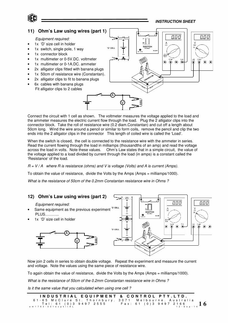
11) Ohm’s Law using wires (part 1)
Equipment required:
• 1x ‘D’ size cell in holder
• 1x switch, single pole, 1 way
• 1x connector block
• 1x multimeter or 0-5V.DC. voltmeter
• 1x multimeter or 0-1A.DC. ammeter
• 2x alligator clips fitted with banana plugs
• 1x 50cm of resistance wire (Constantan).
• 2x alligator clips to fit to banana plugs
• 6x cables with banana plugs
Fit alligator clips to 2 cables
Connect the circuit with 1 cell as shown. The voltmeter measures the voltage applied to the load andthe ammeter measures the electric current flow through the load. Plug the 2 alligator clips into theconnector block. Take the roll of resistance wire (0.2 diam.Constantan) and cut off a length about50cm long. Wind the wire around a pencil or similar to form coils, remove the pencil and clip the twoends into the 2 alligator clips in the connector This length of coiled wire is called the ‘Load’.
When the switch is closed, the cell is connected to the resistance wire with the ammeter in series.Read the current flowing through the load in milliamps (thousandths of an amp) and read the voltageacross the load in volts. Note these values. Ohm’s Law states that in a simple circuit, the value ofthe voltage applied to a load divided by current through the load (in amps) is a constant called the‘Resistance’ of the load.
R = V / A where R is resistance (ohms) and V is voltage (Volts) and A is current (Amps).
To obtain the value of resistance, divide the Volts by the Amps (Amps = milliamps/1000).
What is the resistance of 50cm of the 0.2mm Constantan resistance wire in Ohms ?
12) Ohm’s Law using wires (part 2)
Equipment required:
• Same equipment as the previous experiment
PLUS………..
• 1x ‘D’ size cell in holder
Now join 2 cells in series to obtain double voltage. Repeat the experiment and measure the currentand voltage. Note the values using the same piece of resistance wire.
To again obtain the value of resistance, divide the Volts by the Amps (Amps = milliamps/1000).
What is the resistance of 50cm of the 0.2mm Constantan resistance wire in Ohms ?
Is it the same value that you calculated when using one cell ?
INSTRUCTION SHEET
I N D U S T R I A L E Q U I P M E N T & C O N T R O L P T Y . L T D .6 1 - 6 5 M c C l u r e S t . T h o r n b u r y . 3 0 7 1 M e l b o u r n e . A u s t r a l i a
T e l : 6 1 ( 0 ) 3 9 4 9 7 2 5 5 5 F a x : 6 1 ( 0 ) 3 9 4 9 7 2 1 6 6e m 1 7 6 3 - 0 0 1 e x p k i t A L 1 2 - S e p - 1 4
1 7
13) Ohm’s Law using wires (part 3)
Continued from experiment 12)
Turn off the current and now take 100m (double length) of the same 0.2mm diameter Constantanresistance wire, coil it up on a pencil and repeat the experiment. Calculate the resistance.
What have you discovered ?
14) Ohm’s Law using wires (part 4)
Continued from experiment 13)
Turn off the current and cut another 100cm piece of 0.2 diameter Constantan wire and join the secondcoiled up wire between the same alligator clips but do not let the coils touch the coils of the first wire.Now the current must flow through 2 wires side by side (this is called connecting ‘in parallel’). Closethe switch and check the current. It should be double the previous current when one wire was usedbecause now 2 coils are connected and each coil is the same length and so the same current shouldflow in each coil.
As previously, divide the volts by the amps to calculate the resistance of the 2 coils in parallel.
Is it the same ohms value as a previous experiment ? Explain why.
15) Ohm’s Law using wires (part 5)
Continued from experiment 14)
Repeat the experiment 13) but use only one cell and 100cm length of 0.2mm diameter COPPER wire.As previously, divide the volts by the amps to calculate the resistance of the copper wire. Comparethe resistance of the copper wire with the value you calculated in experiment 13) for the 100cm ofConstantan resistance wire.
Which metal has the higher resistance, copper or Constantan ?
About how many times more resistive is 0.2mm diameter Constantan compared to 0.2mm diametercopper ?

INSTRUCTION SHEET
I N D U S T R I A L E Q U I P M E N T & C O N T R O L P T Y . L T D .6 1 - 6 5 M c C l u r e S t . T h o r n b u r y . 3 0 7 1 M e l b o u r n e . A u s t r a l i a
T e l : 6 1 ( 0 ) 3 9 4 9 7 2 5 5 5 F a x : 6 1 ( 0 ) 3 9 4 9 7 2 1 6 6e m 1 7 6 3 - 0 0 1 e x p k i t A L 1 2 - S e p - 1 4
1 8
16) Using Ohm’s Law: Single resistors and series connection.
Equipment required:
• 2x ‘D’ size cell in holder
• 1x switch, single pole, 1 way
• 1x resistor, 50 ohms
• 1x resistor, 100 ohms
• 1x multimeter or 0-5V DC v/m
• 1x multimeter or 0-100mA DC a/m
• 2x alligator clips to fit to ban.plugs
• 6x cables with banana plugs
Fit alligator clips to 2 cables
Up to now we have used wires to make resistance, but resistors of many different values are availablefor building electrical and electronic circuits. Values of less than 0.1 ohms up to millions of ohms areavailable. In this kit there are 3x resistors and for this experiment we will use these instead of wires.The current will be small, so select DC and 200mA on the ammeter range.
Connect the circuit with 2 cells as shown but connect the alligator clip to only one cell. The voltmetermeasures the voltage applied to the resistor load and the ammeter measures the electric current flowthrough the load in milliamps. To change milliamps to amps, divide by 1000.
Before reading the ammeter, use Ohm’s Law to calculate the current that SHOULD flow through the50 ohm resistor
1x cell should be about 1.5 volts and the resistor is 50 ohms.
Ohm’s Law states that R = V / A Resistance in ohms = Volts divided by Amps
Therefore, A = V / R Current in Amps = Volts divided by Resistance in ohms.
So, Amps should be 1.5V / 50ohms = 0.030 amps (= 30/1000 amps = 30 milliamps)
Now, close the circuit and measure the current to find out if you are correct. Note the value.
If the resistance was double (100 ohms) would you expect the current to be double or half ?
After deciding, replace the 50 ohm resistor with 100 ohm value and check. Were you correct ?
Move the alligator clip to now use 2 cells in series. Voltage should now be close to 3 volts. If thevoltage is double, the current should double. Measure and see if this is correct.
Try with the 50 ohm and the 100 ohm resistors in series to make total resistance of 150 ohms.
Using one cell and later using 2 cells, calculate the expected currents then measure the current to findout if you are correct.
Note the various voltages and currents like the table below:
Cells used Voltage Resistance Current mA Current in A
1 1.5 volts 50 ohms 30 mA 0.030 A
2 3 volts 50 ohms 60 mA 0.060 A
1 1.5 volts 100 ohms 15 mA 0.015 A
2 3 volts 100 ohms 30 mA 0.030 A
2 3 volts 150 ohms 20 mA 0.020 A

INSTRUCTION SHEET
I N D U S T R I A L E Q U I P M E N T & C O N T R O L P T Y . L T D .6 1 - 6 5 M c C l u r e S t . T h o r n b u r y . 3 0 7 1 M e l b o u r n e . A u s t r a l i a
T e l : 6 1 ( 0 ) 3 9 4 9 7 2 5 5 5 F a x : 6 1 ( 0 ) 3 9 4 9 7 2 1 6 6e m 1 7 6 3 - 0 0 1 e x p k i t A L 1 2 - S e p - 1 4
1 9
17) Using Ohm’s Law: Is a lamp a resistor ?
Equipment required:
• 2x ‘D’ size cell in holder
• 1x switch, single pole, 1 way
• 1x lamp 2.5V
• 1x multimeter or 0-5V.DC. voltmeter
• 1x multimeter or 0-1A.DC. ammeter
• 2x alligator clips to fit to banana plugs
• 6x cables with banana plugs
Fit alligator clips to 2 cables
This experiment is similar to the previous one, except we are using one of the lamps instead of a fixedresistor. The lamp is 2.5V. When only one cell is connected (about 1.5V), it will not be fully bright.When both cells in series are used (about 3V), the lamp will be at full brightness.
On the multimeter, select DC and 10 Amps. Close the switch so the lamp lights and measure thevolts and amps and calculate the resistance of the lamp in ohms and note this value.
Now turn off the lamp and connect the alligator clip so both cells are used in series. Close the switchand measure volts and amps again.
The volts are now double, but what do you notice about the amps ? Have amps exactly doubled ?Calculate the resistance of the lamp and note this value.
Notice that the resistance of the lamp has changed. The resistance value of the lamp is higher when itis brighter. Notice that in the previous experiment, when the voltage was doubled, the amps alsodoubled. This means that the 50 ohm and 100 ohm resistance values in the previous experiment didnot change their values when the voltage and current was changed.
A lamp is a type of resistor, but it is different from the resistors in the kit. As seen in the previousexperiment, a normal resistor value in ohms remains constant as the voltage changes and as thecurrent through the resistor changes. This experiment shows that a lamp does not behave exactlylike this.
EXERCISES: Take a lamp from the kit, fit a 2.5 volt globe and use the multimeter to measure theresistance of a cold lamp (not glowing). What is the resistance in ohms ? Note the value.
Compare this ‘cold’ lamp resistance with the values you calculated when the lamp was glowing with 1cell and with 2 cells.
Try to explain why the lamp resistance changes if the lamp is brighter.
Is a lamp a good type of resistor to use in electrical circuits ? Why ?

INSTRUCTION SHEET
I N D U S T R I A L E Q U I P M E N T & C O N T R O L P T Y . L T D .6 1 - 6 5 M c C l u r e S t . T h o r n b u r y . 3 0 7 1 M e l b o u r n e . A u s t r a l i a
T e l : 6 1 ( 0 ) 3 9 4 9 7 2 5 5 5 F a x : 6 1 ( 0 ) 3 9 4 9 7 2 1 6 6e m 1 7 6 3 - 0 0 1 e x p k i t A L 1 2 - S e p - 1 4
2 0
18) Connecting two lamps in series: using a ‘short circuit’:
Equipment required:
• 2x ‘D’ size cell in holder
• 1x switch, single pole, 1 way
• 1x switch, single pole, 2 way
• 2x lamps, 2.5 Volt
• 2x alligator clips to fit to banana plugs
• 6x cables with banana plugs
Fit alligator clips to 2 cables
The two cells are connected in series to provide approximately 3 volts to the circuit.
The 2 lamps are connected in series so the same current flows through each of them. The switch isconnected across one lamp so that when the switch is ON, one lamp is ‘short circuited’. This meansthat when the switch is ON, the current will flow through the switch because the resistance of theswitch is zero ohms. The current will flow through the switch and almost zero current will flow throughthe lamp. It is the same as having only one lamp in the circuit.
Making the current flow through a zero ohm circuit around a resistor is called ‘short circuiting’ theresistor. When the switch is turned OFF, the current must flow through the lamp like normal.
Turn the short circuit ON across the second lamp. Connect the cells to the circuit by turning ON theother switch and see the brightness of one lamp.
Turn OFF the short circuit to make two lamps in series. See both lamps glow, but at a lowerbrightness.
Remove one lamp from a lampholder. What happens ? Is your house wired like this ?
Replace the lamp and remove the other lamp. What happens ?
Turn ON the short circuit. Explain what will happen if you remove the lamp that is short circuited.
Try it and see if you are correct.

INSTRUCTION SHEET
I N D U S T R I A L E Q U I P M E N T & C O N T R O L P T Y . L T D .6 1 - 6 5 M c C l u r e S t . T h o r n b u r y . 3 0 7 1 M e l b o u r n e . A u s t r a l i a
T e l : 6 1 ( 0 ) 3 9 4 9 7 2 5 5 5 F a x : 6 1 ( 0 ) 3 9 4 9 7 2 1 6 6e m 1 7 6 3 - 0 0 1 e x p k i t A L 1 2 - S e p - 1 4
2 1
19) Connecting two resistors in series:
Equipment required:
• 2x ‘D’ size cell in holder
• 1x switch, single pole, 1 way
• 1x resistor 50 ohms
• 1x resistor 100 ohms
• 1x multimeter or 0–5 V voltmeter
• 1x multimeter or ammeter 0-200mA.
• 2x alligator clips to fit to banana plugs
• 7x cables with banana plugs
Fit alligator clips to 2 cables
The two cells are connected in series to provide 3 volts to the circuit.
The 2 resistors are in series so the same current will flow through each of them. The ammeter ismeasuring current flowing in milliamps. The voltmeter is connected across one resistor. Note thevoltage and then connect the voltmeter across the other resistor (or you can connect a separatevoltmeter across each resistor).
Using R = V / A (Ohm’s Law) calculate the value of each resistor (R1 and R2). Then connect avoltmeter across both resistors and calculate the total resistance (R3).
Does R1 + R2 = R3 ? Do two resistors in series equal the sum of both resistors ?
20) Voltage Divider using resistors in series:
Equipment required:
Same circuit as experiment 19.
The previous experiment you measured the resistance of each resistor and showed that two resistorsin series add together to make a higher value resistor in ohms.
This time, note the voltage you measured across each resistor (V1 and V2) and note the voltage ofthe power supply (the 2 cells in series, V3). See that V1 + V2 = V3.
The value of V1 is part of the total voltage, so the two resistors are forming a voltage divider.
If the 2 resistors were the same value in ohms, what would the voltage be at the mid point ?
If both resistors were 50 ohms, or if both resistors were 100 ohms or 500 ohms or 1000 ohms, wouldthis change the result ?
INSTRUCTION SHEET
I N D U S T R I A L E Q U I P M E N T & C O N T R O L P T Y . L T D .6 1 - 6 5 M c C l u r e S t . T h o r n b u r y . 3 0 7 1 M e l b o u r n e . A u s t r a l i a
T e l : 6 1 ( 0 ) 3 9 4 9 7 2 5 5 5 F a x : 6 1 ( 0 ) 3 9 4 9 7 2 1 6 6e m 1 7 6 3 - 0 0 1 e x p k i t A L 1 2 - S e p - 1 4
2 2
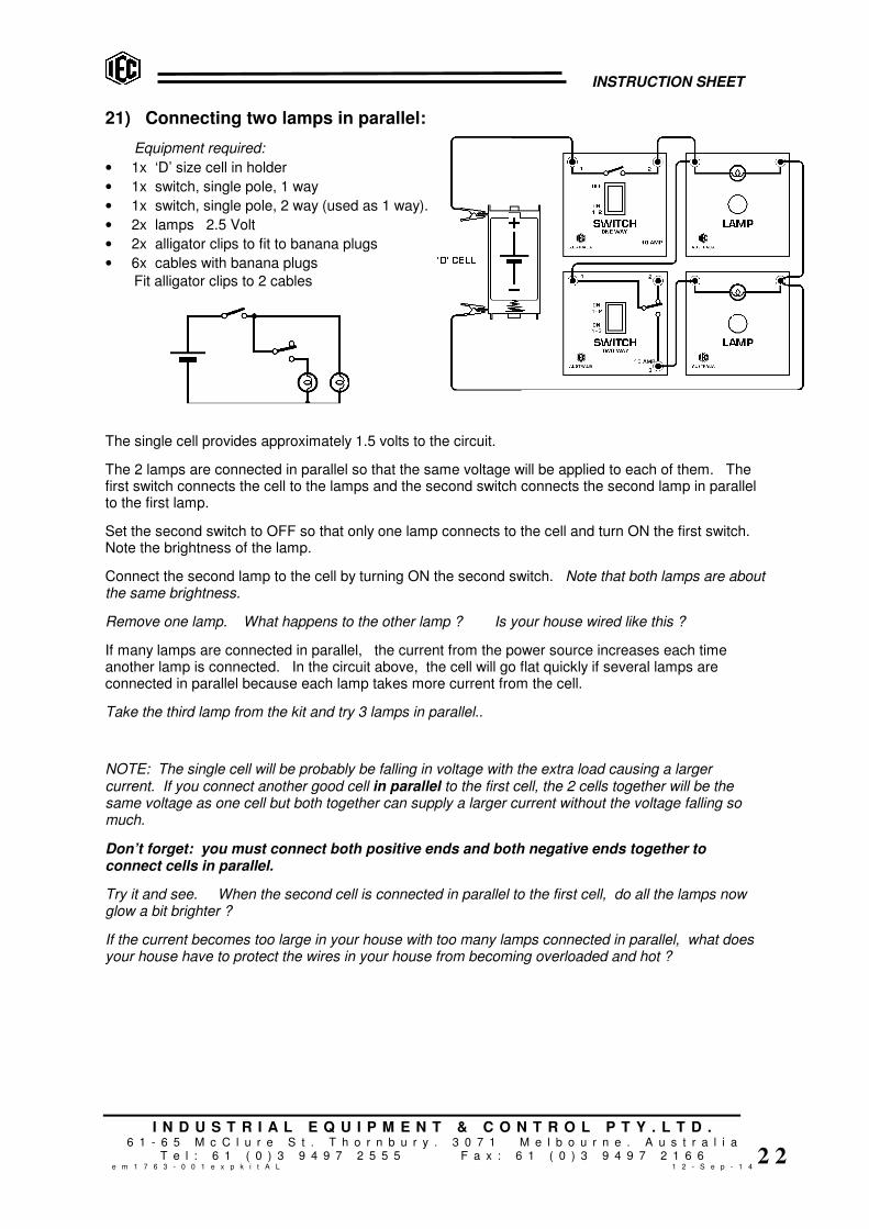
21) Connecting two lamps in parallel:
Equipment required:
• 1x ‘D’ size cell in holder
• 1x switch, single pole, 1 way
• 1x switch, single pole, 2 way (used as 1 way).
• 2x lamps 2.5 Volt
• 2x alligator clips to fit to banana plugs
• 6x cables with banana plugs
Fit alligator clips to 2 cables
The single cell provides approximately 1.5 volts to the circuit.
The 2 lamps are connected in parallel so that the same voltage will be applied to each of them. Thefirst switch connects the cell to the lamps and the second switch connects the second lamp in parallelto the first lamp.
Set the second switch to OFF so that only one lamp connects to the cell and turn ON the first switch.Note the brightness of the lamp.
Connect the second lamp to the cell by turning ON the second switch. Note that both lamps are aboutthe same brightness.
Remove one lamp. What happens to the other lamp ? Is your house wired like this ?
If many lamps are connected in parallel, the current from the power source increases each timeanother lamp is connected. In the circuit above, the cell will go flat quickly if several lamps areconnected in parallel because each lamp takes more current from the cell.
Take the third lamp from the kit and try 3 lamps in parallel..
NOTE: The single cell will be probably be falling in voltage with the extra load causing a largercurrent. If you connect another good cell in parallel to the first cell, the 2 cells together will be thesame voltage as one cell but both together can supply a larger current without the voltage falling somuch.
Don’t forget: you must connect both positive ends and both negative ends together toconnect cells in parallel.
Try it and see. When the second cell is connected in parallel to the first cell, do all the lamps nowglow a bit brighter ?
If the current becomes too large in your house with too many lamps connected in parallel, what doesyour house have to protect the wires in your house from becoming overloaded and hot ?

INSTRUCTION SHEET
I N D U S T R I A L E Q U I P M E N T & C O N T R O L P T Y . L T D .6 1 - 6 5 M c C l u r e S t . T h o r n b u r y . 3 0 7 1 M e l b o u r n e . A u s t r a l i a
T e l : 6 1 ( 0 ) 3 9 4 9 7 2 5 5 5 F a x : 6 1 ( 0 ) 3 9 4 9 7 2 1 6 6e m 1 7 6 3 - 0 0 1 e x p k i t A L 1 2 - S e p - 1 4
2 3
22) Connecting two resistors in parallel:
Equipment required:
• 1x ‘D’ size cell in holder
• 1x switch, single pole, 1 way
• 1x resistor, 50 ohms
• 1x resistor, 100 ohms
• 3x multimeter or ammeters 0-200mA.
• 2x alligator clips to fit to banana plugs
• 8x cables with banana plugs
Fit alligator clips to 2 cables
The single cell provides approximately 1.5 volts to the circuit.
The 2 resistors are connected in parallel so that the same voltage will be applied to each of them. Anammeter is connected in series with each resistor to measure the current flowing in each resistor. Theswitch connects the cell to the resistors. A third ammeter is connected to measure the total currentflowing from the cell.
Set the switch to ON and note the current flowing in each resistor. Note that the cell is connected toeach resistor in parallel, so the voltage on each resistor is the voltage of the cell (1.5 Volts).
Note the total current flowing from the cell.
Note that the total current = the sum of the two resistor currents.
Using 1.5V for the cell voltage, calculate the total resistance of the two resistors in parallel.
R = V / A so, R (ohms) = 1.5 volts / total current in amps (mA x 1000).
Is the value of the total resistance larger or smaller than either of the 2 resistors ?
MATHS: For resistors in parallel, 1/R3 (total resistance) = 1/R1 + 1/R2
When this is transposed by maths, it becomes R3 (total resistance) = (R1 x R2) / (R1 + R2)
For 2 resistors in parallel, the total resistance R3 = (R1 x R2) / (R1 + R2). This is called the “product(multiplication) of the two resistors divided by the sum of the two resistors”.
In this case: 50 x 100 / (50 + 100) = 33.33 ohms.
For many resistors (say 6 resistors) in parallel, the above formula cannot be used. You must use:
1/R6 = 1/R1 + 1/R2 + 1/R3 + 1/R4 + 1/R5 + 1/R6
NOTE: If say 4 resistors are in parallel, you can calculate the total of the first 2 in parallel, then thetotal of the next 2 in parallel, then take the two results and do the same “product over sum” calculationagain to get total of all 4 resistors in parallel.

INSTRUCTION SHEET
I N D U S T R I A L E Q U I P M E N T & C O N T R O L P T Y . L T D .6 1 - 6 5 M c C l u r e S t . T h o r n b u r y . 3 0 7 1 M e l b o u r n e . A u s t r a l i a
T e l : 6 1 ( 0 ) 3 9 4 9 7 2 5 5 5 F a x : 6 1 ( 0 ) 3 9 4 9 7 2 1 6 6e m 1 7 6 3 - 0 0 1 e x p k i t A L 1 2 - S e p - 1 4
2 4
23) Connecting two resistors in parallel, plus another resistor in series:
Equipment required:
• 2x ‘D’ size cell in holder
• 1x switch, single pole, 1 way
• 1x resistor, 50 ohms
• 1x resistor, 100 ohms
• 1x resistor, 500 ohms
• 1x multimeter or ammeter 0-200mA
• 2x alligator clips to fit to banana plugs
• 7x cables with banana plugs
Fit alligator clips to 2 cables
The 2 cells provide approximately 3 volts to the circuit.
The 50 ohm and the 100 ohm resistors are in parallel plus the 500 ohm resistor is in series with theparallel circuit.
From the previous experiment, we know the resistance of the 50 ohm and 100 ohm resistors inparallel is 33.33 ohms (product over sum). We know also that if a resistor is added in series, thevalues add together. So the total resistance of the circuit is 33.33 ohms plus 500 ohms = 533.33ohms.
Measure the total current through the circuit and measure the voltage of the cells and, using Ohm’slaw, calculate the total resistance. R = V / A R (total) = Volts of cells / Amps flowing.
Your current reading will be in milliamps so remember to change milliamps to amps by dividing by1000.
What ohms value do you get ? Is it close to 533.33 ohms ?
USING THE MULTIMETER TO READ OHMS:
To check the values of the resistors, you can select OHMS on the multimeter and you can measurethe ohms exactly. Choose an OHMS range that will suit the expected value of the resistor.
Using the digital ohm meter, measure the value of the 50 ohm and 100 ohm resistors connected inparallel, then add the 500 ohm resistor in series to the parallel pair and measure the whole resistornetwork. Is it close to what you measured and calculated ?

INSTRUCTION SHEET
I N D U S T R I A L E Q U I P M E N T & C O N T R O L P T Y . L T D .6 1 - 6 5 M c C l u r e S t . T h o r n b u r y . 3 0 7 1 M e l b o u r n e . A u s t r a l i a
T e l : 6 1 ( 0 ) 3 9 4 9 7 2 5 5 5 F a x : 6 1 ( 0 ) 3 9 4 9 7 2 1 6 6e m 1 7 6 3 - 0 0 1 e x p k i t A L 1 2 - S e p - 1 4
2 5
24) Internal resistance of Power Source (a dry cell):
Equipment required:
• 1x ‘D’ size cell in holder
• 1x switch, single pole, 1 way
• 1x lampholder fitted with 2.5V lamp
• 1x multimeter or voltmeter 0-5V
• 1x multimeter or ammeter 0-10A
• 4x alligator clips to fit to banana plugs
• 6x cables with banana plugs
Fit alligator clips to 4 cables
Connect a switch and a lamp in series across a single cell (about 1.5V).
Connect voltmeter across the cell to check cell voltage. With switch OFF, note the cell voltage at zeroamps flowing. Turn switch ON. Note the current flowing in amps and note the lower voltage of thecell.
To calculate the internal resistance of the cell, first subtract second voltage from the first voltage toshow the drop in voltage from the cell. Call this Vd.
Call the current flowing A1.
The resistance of the cell (Rc) in ohms causes this voltage difference Vd to occur when A1 currentflows.
Ohm’s Law states: R = V / A
So, cell resistance = Voltage change / Cell current Rc = Vd / A1 Rc = ? ohms
If 2 cells are connected in series, will the total internal resistance of the cells be higher or lower ?
If 2 cells are connected in parallel, will the total internal resistance of the cells be higher or lower ?
INSTRUCTION SHEET
I N D U S T R I A L E Q U I P M E N T & C O N T R O L P T Y . L T D .6 1 - 6 5 M c C l u r e S t . T h o r n b u r y . 3 0 7 1 M e l b o u r n e . A u s t r a l i a
T e l : 6 1 ( 0 ) 3 9 4 9 7 2 5 5 5 F a x : 6 1 ( 0 ) 3 9 4 9 7 2 1 6 6e m 1 7 6 3 - 0 0 1 e x p k i t A L 1 2 - S e p - 1 4
2 6
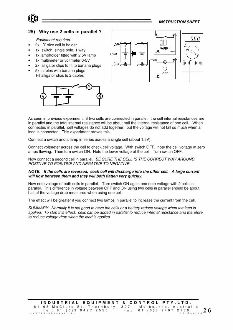
25) Why use 2 cells in parallel ?
Equipment required:
• 2x ‘D’ size cell in holder
• 1x switch, single pole, 1 way
• 1x lampholder fitted with 2.5V lamp
• 1x multimeter or voltmeter 0-5V
• 2x alligator clips to fit to banana plugs
• 5x cables with banana plugs
Fit alligator clips to 2 cables
As seen in previous experiment, if two cells are connected in parallel, the cell internal resistances arein parallel and the total internal resistance will be about half the internal resistance of one cell. Whenconnected in parallel, cell voltages do not add together, but the voltage will not fall so much when aload is connected. This experiment proves this.
Connect a switch and a lamp in series across a single cell (about 1.5V).
Connect voltmeter across the cell to check cell voltage. With switch OFF, note the cell voltage at zeroamps flowing. Then turn switch ON. Note the lower voltage of the cell. Turn switch OFF.
Now connect a second cell in parallel. BE SURE THE CELL IS THE CORRECT WAY AROUND.POSITIVE TO POSITIVE AND NEGATIVE TO NEGATIVE.
NOTE: If the cells are reversed, each cell will discharge into the other cell. A large currentwill flow between them and they will both flatten very quickly.
Now note voltage of both cells in parallel. Turn switch ON again and note voltage with 2 cells inparallel. This difference in voltage between OFF and ON using two cells in parallel should be abouthalf of the voltage drop measured when using one cell.
The effect will be greater if you connect two lamps in parallel to increase the current from the cell.
SUMMARY: Normally it is not good to have the cells or a battery reduce voltage when the load isapplied. To stop this effect, cells can be added in parallel to reduce internal resistance and thereforeto reduce voltage drop when the load is applied.

INSTRUCTION SHEET
I N D U S T R I A L E Q U I P M E N T & C O N T R O L P T Y . L T D .6 1 - 6 5 M c C l u r e S t . T h o r n b u r y . 3 0 7 1 M e l b o u r n e . A u s t r a l i a
T e l : 6 1 ( 0 ) 3 9 4 9 7 2 5 5 5 F a x : 6 1 ( 0 ) 3 9 4 9 7 2 1 6 6e m 1 7 6 3 - 0 0 1 e x p k i t A L 1 2 - S e p - 1 4
2 7
26) Making a voltage divider (or Potentiometer):
Equipment required:
• 2x ‘D’ size cell in holder
• 1x switch, single pole, 1 way
• 1x resistor, 50 ohms
• 1x connector block
• 1x multimeter or voltmeter 0-5V
• 2x alligator clips with ban.plugs fitted.
• 1x resistance wire, 1m x 0.2mm d.
• 2x alligator clips to fit to banana plugs
• 5x cables with banana plugs
Fit alligator clips to 2 cables
Connect a switch and the connector block in series across 2 cells (about 3V). Use about 100cm ofresistance wire either as a straight wire or coiled.
Connect voltmeter between the negative end of the cells and the join between the resistance wire andthe resistor. This connection will measure the voltage across the wire.
Later you will slide the voltmeter connection along the wire to measure voltages along the length of thewire (see illustration).
EXERCISES:
1) If the applied voltage is 3 volts and the resistor is 50 ohms and if the wire was 50 ohms, whatwould the voltage measure across the wire ?
Clue: The total resistance is 100 ohms and the measuring point is 50 ohms (half-way) from the end.
Resistance ratio = 50/100 ohms, therefore, Voltage = 50/100 x 3 volts = 1.5 V
2) If the applied voltage is 3 volts and the resistor is 50 ohms and if the wire was 1 ohm, what wouldthe voltage measure across the wire ?
Clue: The total resistance is 51 ohms and the measuring point is 1 ohm from the end.
Resistance ratio = 1/51 ohms, therefore , Voltage = 1/51 x 3 volts. = 3/51 = 0.0588 V (58.8 mV)
Now, in the above circuit, measure the cell voltage and the voltage across your resistance wire. Youknow that the resistor in series is 50 ohms, so, using the formulae above, calculate the resistance ofthe resistance wire.
An adjustable Voltage Divider:
Move the positive voltmeter connection along the resistance wire and see the voltage rise and fall asyou slide the voltmeter connection along the wire. This is an adjustable voltage divider orPotentiometer.
Take the 50 ohm Potentiometer from the kit and look at the construction. Notice it is a coil ofresistance wire connected to two terminals and a ‘wiper’ that contacts the wire coil. The wiper isconnected to the centre connection and moves around the wire coil as the knob is turned.

INSTRUCTION SHEET
I N D U S T R I A L E Q U I P M E N T & C O N T R O L P T Y . L T D .6 1 - 6 5 M c C l u r e S t . T h o r n b u r y . 3 0 7 1 M e l b o u r n e . A u s t r a l i a
T e l : 6 1 ( 0 ) 3 9 4 9 7 2 5 5 5 F a x : 6 1 ( 0 ) 3 9 4 9 7 2 1 6 6e m 1 7 6 3 - 0 0 1 e x p k i t A L 1 2 - S e p - 1 4
2 8
27) Potentiometer: Using a real potentiometer:
Equipment required:
• 2x ‘D’ size cell in holder
• 1x switch, single pole, 1 way
• 1x resistor, 50 ohms
• 1x potentiometer, 50 ohms
• 2x multimeters or voltmeters 0-5V
• 2x alligator clips to fit to ban.plugs
• 8x cables with banana plugs
Fit alligator clips to 2 cables
Connect the switch, the 50 ohm resistor and the 50 ohm Potentiometer in series across 2 cells (about3V). The two resistance values are the same, so there will be about 1.5V across the resistor andabout 1.5V across the potentiometer.
The wiper of the Potentiometer can move smoothly from one end of the 50 ohms to the other (lookthrough the plastic to see the Potentiometer working). This means that the Potentiometer cansmoothly divide the 1.5V across it from zero volts to 1.5 volts.
Connect one voltmeter across the outside connections of the Potentiometer (sockets 1 & 2) and checkthe voltage is about half the cell voltage (1.5V).
Now connect the other voltmeter from the negative end of the Potentiometer to the moving wiperconnection (sockets 1 & 3). Turn the knob and see the voltage change from zero to about 1.5V.
CAUTION:: A potentiometer can adjust its resistance from zero to maximum. If apotentiometer is connected directly to a power source by using socket 3, there is a dangerthat you can place zero resistance across the power source. A very large current will flow andthe Potentiometer will be destroyed.
QUESTION: So, explain the purpose of the 50 ohm resistor in this circuit ?
ANSWER: If the 50 ohm resistor was not there, the potentiometer would work OK and divide the cellvoltage of 3V from zero to 3V. It is not required for the circuit to work, but it provides resistance inthe circuit to protect the potentiometer from damage if accidentally connected to the cells by the wrongsockets.
Think of other uses for a Potentiometer or voltage divider…………..
Maybe you need exactly 2.0 volts for an experiment. So, it can be placed across a voltage source(cell or power supply) using sockets 1 & 2 ONLY and then adjusted to provide an EXACT voltagebetween sockets 1 & 3.

INSTRUCTION SHEET
I N D U S T R I A L E Q U I P M E N T & C O N T R O L P T Y . L T D .6 1 - 6 5 M c C l u r e S t . T h o r n b u r y . 3 0 7 1 M e l b o u r n e . A u s t r a l i a
T e l : 6 1 ( 0 ) 3 9 4 9 7 2 5 5 5 F a x : 6 1 ( 0 ) 3 9 4 9 7 2 1 6 6e m 1 7 6 3 - 0 0 1 e x p k i t A L 1 2 - S e p - 1 4
2 9
28) Rheostat (variable resistor): Using a potentiometer as rheostat:
Equipment required:
• 2x ‘D’ size cell in holder
• 1x switch, single pole, 1 way
• 1x lamp 2.5V
• 1x potentiometer, 50 ohms
• 2x multimeters or voltmeters, 0-5V
• 2x alligator clips to fit to banana plugs
• 8x cables with banana plugs
Fit alligator clips to 2 cables
Connect the switch, the Potentiometer sockets 1 & 3 and the lamp in series across the 3V powersource. As the Potentiometer knob is turned, the resistance between sockets 1 & 3 will change fromzero to 50 ohms. This connection makes a variable resistance or ‘Rheostat’.
Connect one voltmeter across the lamp and connect the other voltmeter across the rheostat.
Close the switch and turn the knob to change the resistance in series with the lamp. This change inresistance from zero to 50 ohms will change the current flowing through the lamp and it will smoothlyalter from bright to dim.
You now have a simple lamp dimmer.
Check the change in voltage on the lamp as you dim it.
Check the change in voltage across the rheostat as it dims the lamp. Note that the two voltages addtogether to always equal the voltage of the cells (about 3V).
Think of other uses for a Rheostat…………
• It can change the heating in a resistance wire.
• It can reduce the volume of a loud speaker.
• It can be used as an “unknown” resistor value in experiments.
• It can be adjusted to be a certain resistance (measured by ohm meter) and then used in otherexperiments as that value.

INSTRUCTION SHEET
I N D U S T R I A L E Q U I P M E N T & C O N T R O L P T Y . L T D .6 1 - 6 5 M c C l u r e S t . T h o r n b u r y . 3 0 7 1 M e l b o u r n e . A u s t r a l i a
T e l : 6 1 ( 0 ) 3 9 4 9 7 2 5 5 5 F a x : 6 1 ( 0 ) 3 9 4 9 7 2 1 6 6e m 1 7 6 3 - 0 0 1 e x p k i t A L 1 2 - S e p - 1 4
3 0
29) Creating heat energy from electrical energy:
Equipment required:
• 1x Power Supply, 2-12V.AC/DC
• 1x switch, single pole, 1 way
• 1x connector block
• 2x banana plugs fitted to alligator clips.
• 1x resistance wire, 30cm x 0.2mm d.
• 3x cables with banana plugs
WARNING: This experiment makes wires heat and can burn. Do not touch hot wires.
Connect a switch and connector block in series across the DC terminals of the power supply. Look atthe circuit diagram and fit the banana plug alligator clip connectors as shown. Cut 30cm length ofresistance wire and hold it between the 2 alligator clips so it is taut.
Set the power supply to 2V and turn on by switch at rear panel. Cut small strips of paper, creasethem to make a vee shape upside down and hang them on the wire. Do not touch the wire withfingers. Is the wire becoming hot ?
Select 4 volts on the power supply and check wire for heating. Select 6 volts on the power supplyand check if the paper pieces are charring or smoking and showing signs of being burned.
Select a voltage that makes the wire just gently glow. If you can find some styrene foam packaginganywhere, keep the wire taut and you can neatly cut the foam by using this ‘hot wire’ cutter.
30) Creating light energy from electrical energy:
Keep the same circuit as above experiment but reduce the voltage to 2V and turn off the PowerSupply. Take the same piece of resistance wire and wind a tight coil on a pencil so that the turns arevery close together (but not touching). Take several coils and stretch them gently to be straight wireagain.
Put this wire (part straight and part closely coiled) between the alligator clips. Check the power supplyis ON and set to 2 volts. Turn on the circuit switch.
Wait for few seconds to see if wire glows. If not, raise voltage to 4 volts. Check again. Raise voltageto 6 volts. Notice that when the coils are close together the wire beginning to glow makes the othercoils glow because the coils heat one another.
Notice the straight wire is not glowing because the circulating air is removing the heat from the wire.
Blow on the coils and watch the glowing stop suddenly as the air takes the heat away.
Raise the voltage until the wire glows brightly and gives off heat AND light energy.
Good efficiency means that you receive good results from a circuit with the minimum amount ofenergy used. For the above circuit, the energy appears as both heat and light.
For lighting, do you think this method is very efficient ? Explain why ?

INSTRUCTION SHEET
I N D U S T R I A L E Q U I P M E N T & C O N T R O L P T Y . L T D .6 1 - 6 5 M c C l u r e S t . T h o r n b u r y . 3 0 7 1 M e l b o u r n e . A u s t r a l i a
T e l : 6 1 ( 0 ) 3 9 4 9 7 2 5 5 5 F a x : 6 1 ( 0 ) 3 9 4 9 7 2 1 6 6e m 1 7 6 3 - 0 0 1 e x p k i t A L 1 2 - S e p - 1 4
3 1
31) Making a fuse:
Equipment required:
• 1x ‘D’ size cell in holder
• OR……..
• 1x Power Supply, 2-12V.AC/DC
• 1x switch, single pole, 1 way
• 1x connector block
• 2x banana plugs fitted to alligator clips
• 1x length of fuse wire 0.05mm diam.
• 3x cables with banana plugs
Fit alligator clips to 2 cables (if using cells)
Connect a switch and connector block in series across the cell or across the AC or DC terminals of apower supply. Look at the circuit diagram and fit the banana plug/alligator clip connectors as shown.Cut 10cm length of thin fuse wire and wrap it and hold it between the 2 alligator clips.
If using a power supply, set the power supply to 2V and turn on by switch at rear panel.
Switch ON the circuit switch and the fuse wire will carry a large current and get so hot that it will giveoff light and will melt (fuse will blow). Try again at 4 volts or use 2 cells in series. It will blow fasterbecause more current will flow through the wire.
Try another fuse using double the length of fuse wire. It should blow again.
A fuse is a device that will blow to make the circuit dead if the current exceeds a certain value. It is asafety device used in houses on all electrical circuits. The fuse wire is fitted inside a removable plugthat fits into a special socket. Fuses for low current circuits have small diameter wire and circuits forlarge currents use thicker wire.
Fuses are old fashioned nowadays. Do you know the name of the device that has replaced fuses ?
If the fuse wire is thicker, it requires more current to blow it.
Try using the 0.2mm diameter copper wire as a fuse.
Can you get enough current from the power supply to blow it ?

INSTRUCTION SHEET
I N D U S T R I A L E Q U I P M E N T & C O N T R O L P T Y . L T D .6 1 - 6 5 M c C l u r e S t . T h o r n b u r y . 3 0 7 1 M e l b o u r n e . A u s t r a l i a
T e l : 6 1 ( 0 ) 3 9 4 9 7 2 5 5 5 F a x : 6 1 ( 0 ) 3 9 4 9 7 2 1 6 6e m 1 7 6 3 - 0 0 1 e x p k i t A L 1 2 - S e p - 1 4
3 2
32) Power in an electrical circuit:
Equipment required:
• 1x Power Supply, 2-12V.AC/DC
• 1x switch, single pole, 1 way
• 1x switch, 2 way (used as 1 way)
• 2x lampholders with 12V lamps fitted
• 1x multimeter or voltmeter 0-12V.DC.
• 1x multimeter or ammeter 0-10A.DC.
• 8x cables with banana plugs
Connect a switch and 2 lamps in parallel with one lamp controlled by the second switch across the DCterminals of the power supply. Connect the voltmeter to measure the voltage across the lamps andconnect the ammeter to measure the total current flowing.
If using a power supply, set the power supply to 2V and turn on by switch at rear panel. Turn ON thefirst switch so the one lamp is connected. Raise the volts on the power supply until the lamp isglowing brightly (about 10 or 12 volts).
Note the volts and the amps measured on the meters.
The unit for power is Watts (W). This is the result of multiplying the volts across a load by the currentflowing through the load. Watts = Volts x Amps W = V x A
What is the power consumed by the one lamp ?
Switch ON the second switch so that both lamps are in parallel and both glowing brightly. Both lampshave the same voltage across them but see that the current is approximately double.
Calculate Watts again W = V x A. See that 2 lamps consume double the power of one lamp.
Change the voltage to a lower value and read the current again. Lower the volts so the globes are justglowing a dull red. See the heat in the filaments increase as the voltage is increased. The filamentsinside the globes are made from a special resistance wire that can glow white hot and will not melt.The name of this special metal is ‘Tungsten’.
Feel the heat coming from the lamps as they are glowing. Notice that as the power is higher, theamount of heat and light given off is greater. The power in any electrical circuit is given off as heatand sometimes light.

INSTRUCTION SHEET
I N D U S T R I A L E Q U I P M E N T & C O N T R O L P T Y . L T D .6 1 - 6 5 M c C l u r e S t . T h o r n b u r y . 3 0 7 1 M e l b o u r n e . A u s t r a l i a
T e l : 6 1 ( 0 ) 3 9 4 9 7 2 5 5 5 F a x : 6 1 ( 0 ) 3 9 4 9 7 2 1 6 6e m 1 7 6 3 - 0 0 1 e x p k i t A L 1 2 - S e p - 1 4
3 3
33) Making a heater for water:
Equipment required:
• 1x Power Supply, 2-12V.AC/DC
• 1x switch, single pole, 1 way
• 1x connector block
• 2x banana plugs fitted to alligator clips
• 1x 30cm of resistance wire 0.2mm diam.
• 3x cables with banana plugs
Connect a switch and connector block in series across the DC terminals of the power supply. Look atthe circuit diagram and fit the banana plug/alligator clip connectors as shown. Cut 30cm length of0.2mm diameter resistance wire, coil it on a pencil and hold it between the 2 alligator clips.
Set the power supply to 2V and turn on by switch at rear panel.
Take a drinking glass and invert the connector block with all the resistance wire coil under the water.Do not allow the alligator clips to go in the water or they will rust.
Turn ON the switch and allow current to flow through the resistance wire.
Raise the volts and observe the resistance wire. Why does it not glow like previous experiments ?
The water will slowly rise in temperature as the hot resistance wire heats the water.
To double the heating, wind another heating element and connect it in parallel to the first element(twist the tails together and hold in the alligator clips). Do not allow the coils to touch together.
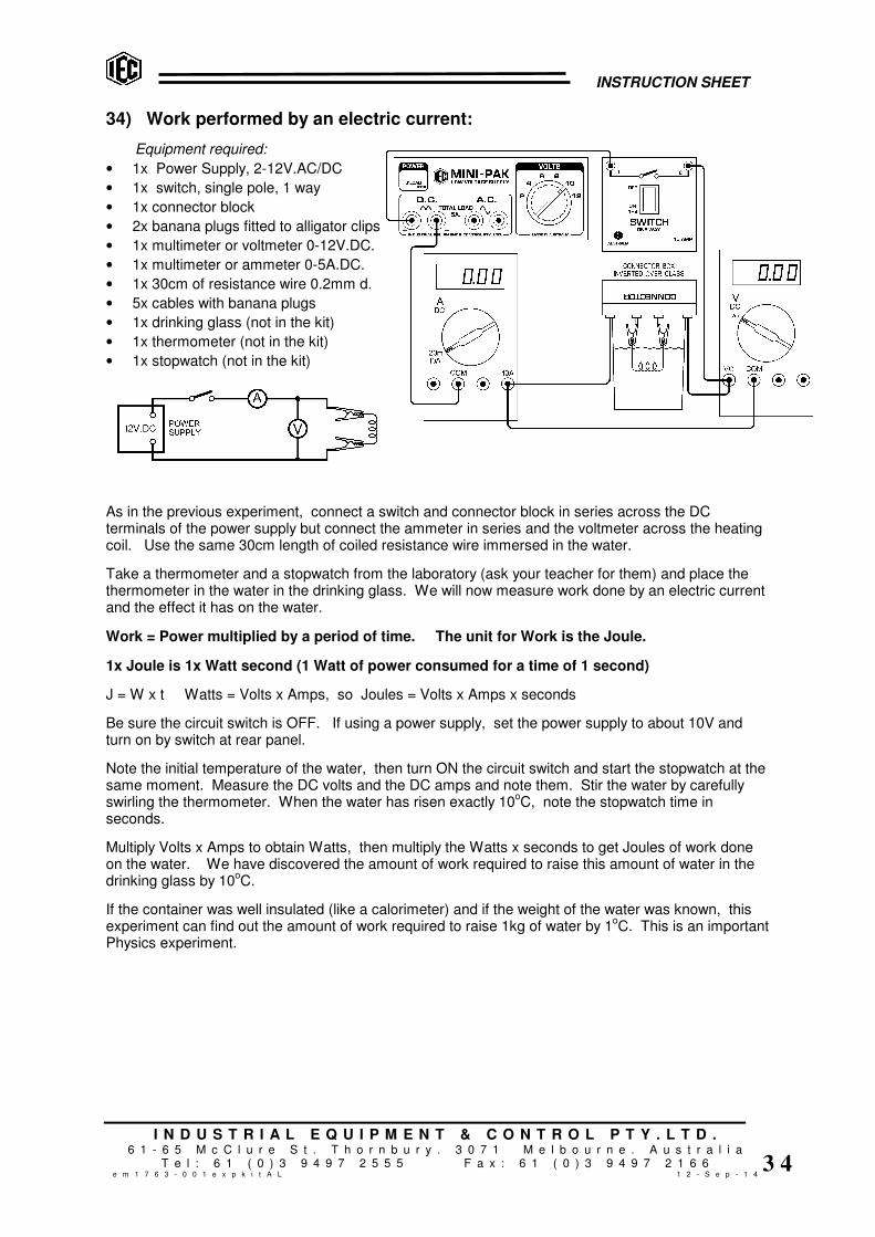
INSTRUCTION SHEET
I N D U S T R I A L E Q U I P M E N T & C O N T R O L P T Y . L T D .6 1 - 6 5 M c C l u r e S t . T h o r n b u r y . 3 0 7 1 M e l b o u r n e . A u s t r a l i a
T e l : 6 1 ( 0 ) 3 9 4 9 7 2 5 5 5 F a x : 6 1 ( 0 ) 3 9 4 9 7 2 1 6 6e m 1 7 6 3 - 0 0 1 e x p k i t A L 1 2 - S e p - 1 4
3 4
34) Work performed by an electric current:
Equipment required:
• 1x Power Supply, 2-12V.AC/DC
• 1x switch, single pole, 1 way
• 1x connector block
• 2x banana plugs fitted to alligator clips
• 1x multimeter or voltmeter 0-12V.DC.
• 1x multimeter or ammeter 0-5A.DC.
• 1x 30cm of resistance wire 0.2mm d.
• 5x cables with banana plugs
• 1x drinking glass (not in the kit)
• 1x thermometer (not in the kit)
• 1x stopwatch (not in the kit)
As in the previous experiment, connect a switch and connector block in series across the DCterminals of the power supply but connect the ammeter in series and the voltmeter across the heatingcoil. Use the same 30cm length of coiled resistance wire immersed in the water.
Take a thermometer and a stopwatch from the laboratory (ask your teacher for them) and place thethermometer in the water in the drinking glass. We will now measure work done by an electric currentand the effect it has on the water.
Work = Power multiplied by a period of time. The unit for Work is the Joule.
1x Joule is 1x Watt second (1 Watt of power consumed for a time of 1 second)
J = W x t Watts = Volts x Amps, so Joules = Volts x Amps x seconds
Be sure the circuit switch is OFF. If using a power supply, set the power supply to about 10V andturn on by switch at rear panel.
Note the initial temperature of the water, then turn ON the circuit switch and start the stopwatch at thesame moment. Measure the DC volts and the DC amps and note them. Stir the water by carefullyswirling the thermometer. When the water has risen exactly 10
oC, note the stopwatch time in
seconds.
Multiply Volts x Amps to obtain Watts, then multiply the Watts x seconds to get Joules of work doneon the water. We have discovered the amount of work required to raise this amount of water in thedrinking glass by 10
oC.
If the container was well insulated (like a calorimeter) and if the weight of the water was known, thisexperiment can find out the amount of work required to raise 1kg of water by 1
oC. This is an important
Physics experiment.

INSTRUCTION SHEET
I N D U S T R I A L E Q U I P M E N T & C O N T R O L P T Y . L T D .6 1 - 6 5 M c C l u r e S t . T h o r n b u r y . 3 0 7 1 M e l b o u r n e . A u s t r a l i a
T e l : 6 1 ( 0 ) 3 9 4 9 7 2 5 5 5 F a x : 6 1 ( 0 ) 3 9 4 9 7 2 1 6 6e m 1 7 6 3 - 0 0 1 e x p k i t A L 1 2 - S e p - 1 4
3 5
35) Voltage created by chemistry:
Equipment required:
• 1x connector block
• 2x banana plugs fitted to alligator clips
• 1x pair Zinc & Copper plates
• 1x multimeter or milliammeter 0-20mA.DC.
• 2x cables with banana plugs
• 1x drinking glass (not in the kit)
• normal table salt (not in the kit)
Connect the simple circuit as shown in the diagram. The ammeter is connected between two platesof dissimilar metals. Immerse the Zinc and Copper plates into the water as seen in the diagram.
If the water is clean, there will be zero current on the ammeter.
Add some salt to the water. What do you see on the milliammeter ?
Which direction is the current flowing ? From zinc to copper ? or copper to zinc ?
When 2 dissimilar metals are immersed in an electrolyte (conductive liquid), a current flows betweenthem. This is caused by the atomic structure of the metals and the number of electrons in their atoms.Electrons are released by one metal into the electrolyte and electrons are absorbed by the other metal.
Which metal is releasing electrons ?
Clue: Remember that electron flow in any circuit is in the reverse direction to conventional currentflow as measured by a meter.
NOTE: Dry cell batteries and wet cell batteries all create voltage by chemical methods but, becauseof the need for dangerous acids, these battery experiments are not part of this manual.

INSTRUCTION SHEET
I N D U S T R I A L E Q U I P M E N T & C O N T R O L P T Y . L T D .6 1 - 6 5 M c C l u r e S t . T h o r n b u r y . 3 0 7 1 M e l b o u r n e . A u s t r a l i a
T e l : 6 1 ( 0 ) 3 9 4 9 7 2 5 5 5 F a x : 6 1 ( 0 ) 3 9 4 9 7 2 1 6 6e m 1 7 6 3 - 0 0 1 e x p k i t A L 1 2 - S e p - 1 4
3 6
36) Capacitors: Charge and voltage:
Equipment required:
• 1x Power Supply, 2-12V.AC/DC
• 1x switch, single pole, 1 way
• 1x capacitor 10uF
• 1x multimeter or voltmeter 0-20V.DC.
• 5x cables with banana plugs
A capacitor is a device that can store electrical energy and give out the energy at a later time. Readabout capacitors in the Glossary. The unit is Farad. This is a huge amount of capacitance so thenormal unit used is millionths of a Farad (called microfarads or ‘uF’).
Set the power supply to 12V.DC. and, using a switch, connect the DC voltage to the discharged(empty) 10uF capacitor. When the switch is closed, the current from the power supply rushes intothe capacitor to charge it. As the capacitor charges, the current falls to zero.
The power supply will instantly ‘charge’ the capacitor to the maximum voltage coming from the powersupply. This is called ‘peak voltage’ which is higher than the DC voltage as measured by a DC meter.
IMPORTANT NOTE: The power supply provides “unfiltered” DC voltage. Read about “Filter” in theGlossary. Also read about “Peak Voltage” in the Glossary.
Turn the switch OFF to disconnect the power supply and leave the voltmeter connected to thecapacitor to see the voltage slowly falling as the capacitor discharges its voltage through the meter’sresistance. A digital meter has a very high resistance and it will take a long time for the capacitor todischarge. Analogue meters have a lower resistance, therefore if an analogue meter is used, thecapacitor will discharge much more quickly through the meter resistance.
Charge the capacitor again to maximum power supply voltage. Again disconnect the power supplyand, using a cable, connect the two capacitor sockets together. Notice the small spark as the energyin the capacitor instantly discharges.

INSTRUCTION SHEET
I N D U S T R I A L E Q U I P M E N T & C O N T R O L P T Y . L T D .6 1 - 6 5 M c C l u r e S t . T h o r n b u r y . 3 0 7 1 M e l b o u r n e . A u s t r a l i a
T e l : 6 1 ( 0 ) 3 9 4 9 7 2 5 5 5 F a x : 6 1 ( 0 ) 3 9 4 9 7 2 1 6 6e m 1 7 6 3 - 0 0 1 e x p k i t A L 1 2 - S e p - 1 4
3 7
37) Capacitors: Charge one capacitor from another:
Equipment required:
• 1x Power Supply, 2-12V.AC/DC
• 1x switch, single pole, 1 way
• 1x switch, single pole, 2 way
• 1x capacitor 10uF
• 2x capacitors 5uF
• 2x digital multimeter 0-20V.DC.
• 8x cables with banana plugs
Connect the 1 way switch from the power supply and connect the 2 way switch so that in one directionthe 10uF capacitor is charged from the power supply and in the other direction the 10uF capacitordisconnects from the power supply and discharges into one of the 5uF capacitors. Connect thevoltmeter across the 10 microfarad capacitor.
Discharge both capacitors by shorting them with a cable. With the 2 way switch, select the 10uFcapacitor. Turn on the power supply and select 12V.DC. Turn on the 1 way switch to charge the10uF capacitor. Note the DC charged voltage.
Now use the 2 way switch to dump the charge of the 10uF capacitor into the 5uF capacitor. When thetwo capacitors connect, their voltages must be equal. Note the new voltage as the 10uF capacitorloses some charge into the 5uF capacitor.
MATHS: If the 10uF capacitor had say 20 volts charge, say energy is 20Vx 10uF = 200 units. Whenthe total capacitance is 10+5 = 15uF, the voltage should be 200/15 = 13.3 volts.
What were your results ?
Discharge the capacitors. If you swap the 5uF and the 10uF capacitors, what voltage should be onthe 15uF combination ?
Original energy: 20Vx5uF = 100 units. Voltage on 15uF should be 100/15 = 6.7 volts.
What were your results ?
Discharge the capacitors. NOW use a cable to connect the two 5uF capacitors in series. Use thiscombination to charge to full voltage and dump this into the 10uF capacitor. If the voltage is lowerthan using one 5uF capacitor, this means that putting capacitors in series makes the capacitanceLESS. Try it and see the voltage on the 10uF capacitor.
Original energy: 20Vx2.5uF = 50 units. Voltage on 12.5uF should be 50/12.5 = 4 volts.
What were your results ? So, you have proved that 2x 5uF capacitors in series = 2.5uF.
Discharge the capacitors. Now use 2 cables to connect the two 5uF capacitors in parallel. Use thiscombination to charge to full voltage and dump this into the 10uF capacitor. If the voltage is higherthan using one 5uF capacitor, this means that putting capacitors in parallel makes the capacitanceGREATER. Try it and see the voltage on the 10uF capacitor.
Original energy: 20Vx10uF = 200 units. Voltage on 20uF should be 200/20 = 10 volts.
What were your results ? So, you have proved that 2x 5uF capacitors in parallel = 10uF.
If you fully charge one of the 5uF capacitors and dump its charge into the other 5uF capacitor, whatshould the voltage be on the 10uF combination ? Do you think it would be half voltage ?
Try it and see. Describe what you are discovering about capacitors ?

INSTRUCTION SHEET
I N D U S T R I A L E Q U I P M E N T & C O N T R O L P T Y . L T D .6 1 - 6 5 M c C l u r e S t . T h o r n b u r y . 3 0 7 1 M e l b o u r n e . A u s t r a l i a
T e l : 6 1 ( 0 ) 3 9 4 9 7 2 5 5 5 F a x : 6 1 ( 0 ) 3 9 4 9 7 2 1 6 6e m 1 7 6 3 - 0 0 1 e x p k i t A L 1 2 - S e p - 1 4
3 8
A.C. EXPERIMENTS: Look at the Glossary to learn the meaning of “AC”.
41) AC current through capacitors: Capacitive Reactance:
Equipment required:
• 1x Power Supply, 2-12V.AC/DC
• 1x switch, single pole, 1 way
• 1x capacitor, 10uF
• 2x capacitors, 5uF
• 1x multimeter or voltmeter 0-20V.AC.
• 1x multimeter or ammeter 0-100mA.AC.
• 6x cables with banana plugs
Connect a switch, 10uF capacitor and 200mA ammeter in series across a power supply set to12V.AC. Connect a 20V.AC. voltmeter across the capacitor.
The resistance in ohms of a resistor controls the current flowing through it. A capacitor or inductor (tobe studied later) has a similar “resistance” but it occurs only when AC power is used and it is called“Reactance”. Read about Reactance in the Glossary.
Close the switch and note the AC current flowing through the capacitor and the AC voltage across thecapacitor.
Change the capacitor to a 5uF capacitor and again note the voltage and the AC current flowing.
What do you notice when the capacitance if halved from 10uF to 5uF ?
Use a cable to connect the two 5uF capacitors in series to make a 2.5uF capacitor. Now use these inthe circuit and again note the AC current flowing.
What do you notice when the capacitance is 2.5uF ?
Now connect all 3 capacitors in parallel to make 5uF + 5uF + 10uF = 20uF total.
What do you notice when the capacitance is 20uF ?
The Reactance of the capacitor is AC Volts / AC Amps (similar to a resistor). Take your readings andcalculate the reactance in ohms.
EXAMPLE: say 12V.AC. applied and 37mA (0.037A) in capacitor = 12/0.037 = 324 ohms.
To calculate reactance when the capacitance is known, the formula is: Rc = 1 / (2πfC)
Rc is Capacitive Reactance, π = 3.142, f is frequency (50Hz), C is capacitance in Farads.
For a 10uF capacitor at 50Hz, reactance is: 1 / (2 x 50 x π x 10x10-6
) = 322 ohms
For a 5uF capacitor, reactance is 644 ohms. So we see large capacitors have lower reactance.
NOTE: The above calculations are for pure capacitance. In practice, there is always somecombination of capacitance and resistance (wires etc.) so some resistance should be added to theReactance calculation to give total “Impedance” in ohms.
Read the Glossary about “Impedance”.
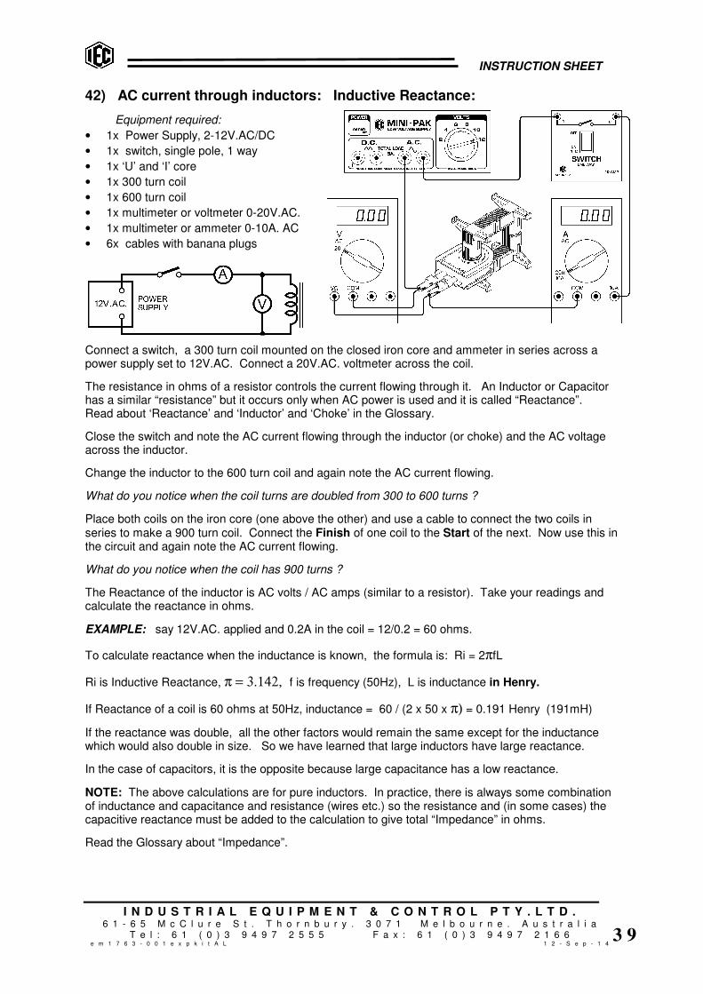
INSTRUCTION SHEET
I N D U S T R I A L E Q U I P M E N T & C O N T R O L P T Y . L T D .6 1 - 6 5 M c C l u r e S t . T h o r n b u r y . 3 0 7 1 M e l b o u r n e . A u s t r a l i a
T e l : 6 1 ( 0 ) 3 9 4 9 7 2 5 5 5 F a x : 6 1 ( 0 ) 3 9 4 9 7 2 1 6 6e m 1 7 6 3 - 0 0 1 e x p k i t A L 1 2 - S e p - 1 4
3 9
42) AC current through inductors: Inductive Reactance:
Equipment required:
• 1x Power Supply, 2-12V.AC/DC
• 1x switch, single pole, 1 way
• 1x ‘U’ and ‘I’ core
• 1x 300 turn coil
• 1x 600 turn coil
• 1x multimeter or voltmeter 0-20V.AC.
• 1x multimeter or ammeter 0-10A. AC
• 6x cables with banana plugs
Connect a switch, a 300 turn coil mounted on the closed iron core and ammeter in series across apower supply set to 12V.AC. Connect a 20V.AC. voltmeter across the coil.
The resistance in ohms of a resistor controls the current flowing through it. An Inductor or Capacitorhas a similar “resistance” but it occurs only when AC power is used and it is called “Reactance”.Read about ‘Reactance’ and ‘Inductor’ and ‘Choke’ in the Glossary.
Close the switch and note the AC current flowing through the inductor (or choke) and the AC voltageacross the inductor.
Change the inductor to the 600 turn coil and again note the AC current flowing.
What do you notice when the coil turns are doubled from 300 to 600 turns ?
Place both coils on the iron core (one above the other) and use a cable to connect the two coils inseries to make a 900 turn coil. Connect the Finish of one coil to the Start of the next. Now use this inthe circuit and again note the AC current flowing.
What do you notice when the coil has 900 turns ?
The Reactance of the inductor is AC volts / AC amps (similar to a resistor). Take your readings andcalculate the reactance in ohms.
EXAMPLE: say 12V.AC. applied and 0.2A in the coil = 12/0.2 = 60 ohms.
To calculate reactance when the inductance is known, the formula is: Ri = 2πfL
Ri is Inductive Reactance, π = 3.142, f is frequency (50Hz), L is inductance in Henry.
If Reactance of a coil is 60 ohms at 50Hz, inductance = 60 / (2 x 50 x π) = 0.191 Henry (191mH)
If the reactance was double, all the other factors would remain the same except for the inductancewhich would also double in size. So we have learned that large inductors have large reactance.
In the case of capacitors, it is the opposite because large capacitance has a low reactance.
NOTE: The above calculations are for pure inductors. In practice, there is always some combinationof inductance and capacitance and resistance (wires etc.) so the resistance and (in some cases) thecapacitive reactance must be added to the calculation to give total “Impedance” in ohms.
Read the Glossary about “Impedance”.

INSTRUCTION SHEET
I N D U S T R I A L E Q U I P M E N T & C O N T R O L P T Y . L T D .6 1 - 6 5 M c C l u r e S t . T h o r n b u r y . 3 0 7 1 M e l b o u r n e . A u s t r a l i a
T e l : 6 1 ( 0 ) 3 9 4 9 7 2 5 5 5 F a x : 6 1 ( 0 ) 3 9 4 9 7 2 1 6 6e m 1 7 6 3 - 0 0 1 e x p k i t A L 1 2 - S e p - 1 4
4 0
43) MAGNETIC FIELDS & INDUCTION:
A FEW BASIC CONCEPTS FOR TEACHERS AND STUDENTS:
Conventions:
1) By convention, a magnetic field is normally depicted flowing from a North pole to a South pole.
2) By theory, electrons (negatively charged) flow from a more negative potential to a more positivepotential whereas conventional current flows from positive potential to negative. In this booklet,we deal only with conventional current flow.
An interesting diversion regarding conventions: The tip of a magnetic compass that points northis the north pole of the needle. To confirm this, hold a bar magnet by cotton at its mid point so it canswing freely. The end marked ‘north’ points to the north magnetic pole of the earth. Of course, thedirection to which the north end of a magnet is attracted must really be a South Pole. So, we mustassume that the naming of the North and South poles of the earth is simply another “convention”.
Current flow: When considering the current flow in a conductor where the conductor itself isgenerating the EMF, the polarity of the current flow appears to be reversed to the polarity of thecurrent flow in the external circuit. For example, if current flows from Positive to Negative in a batteryexternal circuit to say a lamp, it must be flowing from negative to positive INSIDE the battery.
Left Hand Rule (for motors), Right hand Rule (for generators): The left hand rule is a quick wayto determine the direction of movement in a wire when the direction of the magnetic field and thedirection of the current flow is known, as in the case of a motor. The Right Hand Rule using the samemarkings for the fingers, is used to find the direction of the current flow when the motion and themagnetic field directions are known, as in the case of a generator. Try it and see.
Right Fingers rule (for magnets): The Right Fingers Rule is useful to determine which end of aniron circuit becomes North Pole when the direction of the current in the coil is known. This is useful formagnets and transformers.

INSTRUCTION SHEET
I N D U S T R I A L E Q U I P M E N T & C O N T R O L P T Y . L T D .6 1 - 6 5 M c C l u r e S t . T h o r n b u r y . 3 0 7 1 M e l b o u r n e . A u s t r a l i a
T e l : 6 1 ( 0 ) 3 9 4 9 7 2 5 5 5 F a x : 6 1 ( 0 ) 3 9 4 9 7 2 1 6 6e m 1 7 6 3 - 0 0 1 e x p k i t A L 1 2 - S e p - 1 4
4 1
DEMONSTRATORS TO SHOW HOW MAGNETIC FIELD FORM AROUND WIRES:
The kit has a set of 3x demonstrators and these can be used on an overhead projector. Somedesigns use one single turn of thick wire to form the coils. At small currents of 5A, they work well withsensitive ‘plotting compasses’ but a very large current is required through one single turn to create afield strong enough to move iron filings. To overcome this problem, our units have 10 turns of wireso the field is strong enough to move iron filings, but the field shape is the same as one single turn.
Connect a coil unit to the power supply set to 2V.DC. DO NOT EXCEED 2V.DC. OR THE COILWILL OVERHEAD AND THE UNIT WILL BE DAMAGED.
44) MAGNETIC FIELD AROUND A STRAIGHT WIRE: use rectangular coil unit.
Direction of the current: Looking at the rectangular coil with the RED socket at the left side andconnected to the +ve socket on the power supply, the current flow is anticlockwise around the coil.
Place several ‘plotting compasses’ on the flat surface around ONE OF THE LEGS of the coil to seethe shape and direction of the magnetic field formed by a straight wire.
OR…… Sprinkle a small quantity of iron filings on the flat surface close to the leg and tap the surfacewith your fingernail to slightly shake the iron filings. See the lines of magnetic field form on thesurface.
45) MAGNETIC FIELD FROM A SIMPLE COIL: use the small round coil unit.
Direction of the current: Looking at the round coil with the RED socket at the left side andconnected to the +ve socket on the power supply, the current flow is anticlockwise around the coil.
Place several ‘plotting compasses’ on the flat surface around the coil to see the shape and direction ofthe magnetic field formed.
OR…… Sprinkle a small quantity of iron filings on the flat surface and tap the surface with yourfingernail to slightly shake the iron filings. See the lines of magnetic field form on the surface.
46) MAGNETIC FIELD IN A SOLENOID: use the brass spiral coil solenoid unit.
Direction of the current: Looking at the coil with the RED socket facing towards you and connectedto +ve socket on the power supply, the current flow is anticlockwise around the coil.
Place several ‘plotting compasses’ on the flat surface around the solenoid to see the shape anddirection of the magnetic field formed by a solenoid.
OR…… Sprinkle a small quantity of iron filings on the flat surface and tap the surface with yourfingernail to slightly shake the iron filings. See the lines of magnetic field form on the surface.

INSTRUCTION SHEET
I N D U S T R I A L E Q U I P M E N T & C O N T R O L P T Y . L T D .6 1 - 6 5 M c C l u r e S t . T h o r n b u r y . 3 0 7 1 M e l b o u r n e . A u s t r a l i a
T e l : 6 1 ( 0 ) 3 9 4 9 7 2 5 5 5 F a x : 6 1 ( 0 ) 3 9 4 9 7 2 1 6 6e m 1 7 6 3 - 0 0 1 e x p k i t A L 1 2 - S e p - 1 4
4 2
47) THEORY OF INDUCTION:
If a conductor is moved in a magnetic field so that the conductor cuts the lines of magnetism, a smallEMF (Electro Motive Force or Voltage) is induced in the conductor whilst it is moving. The voltagereverses if the direction of motion reverses. If motion stops, the EMF is zero.
If the conductor is moved so that the conductor moves parallel to but does not cut through the linesof magnetic force, the EMF produced is zero.
The size of the EMF increases if the magnetic field is stronger, if the motion is faster or if many turnsare used (see drawing below).
NOTE TO TEACHERS: To measure the current in the circuits below, a very sensitive galvanometeris required. The EMF generated in the wire is very small, so it is very important that the impedanceof the galvanometer is very low (this is often difficult to arrange). It is possible that a coil of 20 turns ormore will be required to generate a high enough voltage to drive a school meter.
48) LEAVE THE COIL ALONE AND MOVE THE MAGNETIC FIELD:
Connect a coil as shown and move a bar magnet as shown. Notice the voltage is generated in thecoil only while the magnet is moving. If the magnet could be made to go back and forth continuously,there would be a ‘back and forth’ voltage generated continuously. Try it and see.
The direction that the galvanometer deflects depends on the direction of the winding of the coil(clockwise or anti-clockwise), the end of the magnet (north or south) and the direction of movement(up or down). Reverse the various things and try it. Remember that if a coil is simply turned over,the direction of the coil (clockwise or anti-clockwise) reverses.

INSTRUCTION SHEET
I N D U S T R I A L E Q U I P M E N T & C O N T R O L P T Y . L T D .6 1 - 6 5 M c C l u r e S t . T h o r n b u r y . 3 0 7 1 M e l b o u r n e . A u s t r a l i a
T e l : 6 1 ( 0 ) 3 9 4 9 7 2 5 5 5 F a x : 6 1 ( 0 ) 3 9 4 9 7 2 1 6 6e m 1 7 6 3 - 0 0 1 e x p k i t A L 1 2 - S e p - 1 4
4 3
49) USE ANOTHER COIL TO PROVIDE THE MAGNETIC FIELD:
The magnetic field does not need to be provided by a permanent magnet. Another coil can be used tocreate a magnetic field. Prove this by placing the long iron bar inside the 200 turn primary coil andapply say 2 or 4 volts DC from a battery to the coil terminals. Notice that the iron bar becomesmagnetised. Use the magnetic compass to prove the bar is magnetised north at one end and south atthe other end. If you know the direction of the winding, use the ‘Fingers Rule’ to check the north andsouth ends of the iron bar.
Place two coils side by side and connect as shown below. One can be the 200 turn primary coil andthe other can be one that you wound yourself with say 100 turns. Apply DC voltage from a battery tothe coil that is not connected to the galvanometer. Notice that when the coil is first connected and themagnetic field is first created, the other coil causes the galvanometer to deflect momentarily. Noticethat when the battery is disconnected and the field collapses, the galvanometer deflects momentarilyin the opposite direction.
Reverse the polarity of the connection and see the galvanometer deflect the opposite direction duringconnection and disconnection.
When the magnetic field is established and no longer forming or collapsing (not varying) thegalvanometer shows zero current.
In the left side arrangement, the two coils are coupled only by air. If an iron bar is placed inside thecoils, the coupling is greatly improved and the galvanometer deflection is increased. It is proven thatan ‘Iron Circuit’ inside the coils greatly improves the magnetic coupling between them.
NOTE: Use a large battery for smooth DC current to be applied to the coil to form the magnetic field.If the DC voltage is only half or full wave rectified, the DC voltage will be rising and falling 100 timesper second and the galvanometer needle will be vibrating and will be much less sensitive.
50) USING AC INSTEAD OF DC:
Using the same arrangement of two coils and the iron bar as shown in the right side illustration above,take a power pack and apply 6 volts AC to the coil from a power supply instead of DC. AC reverses itsdirection 100 times per second. This means that the induced EMF in the other coil will reverse 100times per second. This is so fast that the galvanometer cannot follow the changes and thegalvanometer needle just vibrates slightly and appears to read zero. Replace the Galvanometer (a DCinstrument) with an AC voltmeter which is designed to read AC voltages.
If an oscilloscope is used instead, the AC waveform (a sine wave) can easily be seen.
The presence of a proper closed iron circuit between the coils greatly improves the efficiency of thesystem, but we now have a simple device that is fed with an AC current and continuallygenerates an AC voltage in another coil. This device is called a Transformer.

INSTRUCTION SHEET
I N D U S T R I A L E Q U I P M E N T & C O N T R O L P T Y . L T D .6 1 - 6 5 M c C l u r e S t . T h o r n b u r y . 3 0 7 1 M e l b o u r n e . A u s t r a l i a
T e l : 6 1 ( 0 ) 3 9 4 9 7 2 5 5 5 F a x : 6 1 ( 0 ) 3 9 4 9 7 2 1 6 6e m 1 7 6 3 - 0 0 1 e x p k i t A L 1 2 - S e p - 1 4
4 4
51) TRANSFORMERS and COILS:
Examine the ‘U’ core and the ‘I’ core provided. The kit has 2x 300T coils and 1x 600T coil.
One of the 300 turn coils should be used as the Primary coil. This is the correct number of turns forthe primary coil and will fully magnetise the iron core when connected to 12 volts AC. If connected to12 volts DC, the current will be too high and the coil will get hot. If DC operation is desired, use alower voltage of say 2 to 6 volts DC.
The coils provided have their wire terminated to 4mm sockets so that banana plugs can be used forconnection. The label on each coil shows the number of turns, the Start and Finish (S & F) of thewinding and the direction of current flow around the coil from Start to Finish.
The kit has another 300 turn coil and a 600 turn coil. These can be used as secondary coils or asadditions to the primary coil. If the 600 turn coil is used as a primary coil at 12V.AC., the iron will beonly partly saturated with magnetic field. The transformer will be run but at low efficiency.
52) COIL DIRECTION: CLOCKWISE or ANTI-CLOCKWISE:
The direction of the winding is important to predict the polarity of the induced EMF. Notice that if thecoil is turned upside down, the direction of the winding is reversed and clockwise (same direction asclock hands move on a clock’s face) becomes anti-clockwise when looking from above the coil.
When using DC, the magnetic field produced by the coil will be reversed if the coil winding direction isreversed or if the coil is turned over.
When using AC, if the coil is turned over, the ‘phase’ of the voltage produced in the coil will bereversed (see ‘Phase’ in the glossary). If one secondary coil is reversed to another secondary coil,their phases will be reversed. This means that while the voltage is rising during 100
th of a second in
one coil, the voltage in the other coil will be falling during that short time. If they were joined in series,one coil voltage would subtract from the other coil voltage (see ‘buck’ in the glossary). If both coilshad equal turns, the resultant voltage would be zero. If both coils were the same direction, theresultant voltage would be double (see ‘boost’ in the glossary).
53) CHOOSING METERS FOR MEASUREMENT:
For basic induction work, sensitive DC meters or sensitive Galvanometers are best. Galvanometersmeasure very small currents of around 20 to 50 microamps. This is required to see currents flowingas single conductors are moved in a magnetic field.
Student analogue bench meters of 0-1mA or 0-10mA DC are required for monitoring currents if coilswith many turns are creating current with bar magnets and so on.
For transformer work, AC meters are always required. 0-20V.AC analogue or digital student benchmeter or multimeter is probably best for primary coil volts. Another one or two 0-20V.AC or 0-10V.ACmeters would be required for monitoring secondary coils for experiments.
Two digital or analogue student bench AC ammeters around 0-1A / 0-10A.AC. either single or dualrange will be needed for primary currents. An additional 0-10A.AC analogue meter would be useful forshowing short circuit currents and similar in secondary coils.
Analogue multi-meters can be used but many do not have AC ranges of current that suit theexperiments. Also there is a risk of selecting the wrong voltages or currents.
DIGITAL METERS:
Digital multimeters are supplied in the kit and are more accurate than analogue meters. These canbe used for AC or DC measurements but the changes in voltage will not easily be seen as thenumbers jump. But for general measurement of steady voltages and currents they are satisfactory.

INSTRUCTION SHEET
I N D U S T R I A L E Q U I P M E N T & C O N T R O L P T Y . L T D .6 1 - 6 5 M c C l u r e S t . T h o r n b u r y . 3 0 7 1 M e l b o u r n e . A u s t r a l i a
T e l : 6 1 ( 0 ) 3 9 4 9 7 2 5 5 5 F a x : 6 1 ( 0 ) 3 9 4 9 7 2 1 6 6e m 1 7 6 3 - 0 0 1 e x p k i t A L 1 2 - S e p - 1 4
4 5
54) WHY DO TRANSFORMERS USE ‘AC’ INSTEAD OF ‘DC’ ?
We have seen that the EMF is created in the second coil only when the DC magnetic field changes.There is no EMF when the magnetic field from the first (the primary) coil is steady. Therefore, if AC isused and the field is continually rising falling and reversing 100 times per second, a continuous ACEMF is generated in the second coil. This means that a useful amount of energy is continuously beingtransferred from one coil to the other.
This Induction Kit is to learn about transformers which are devices that run on AC only. AC is appliedto one coil and an iron circuit couples the energy from this coil to another coil. If the number of turns ineach coil is the same, the voltage applied to the primary coil will induce the same voltage in thesecondary coil because the same magnetic field is coupled by the iron core through both coils.
If the secondary coil has say half the number of turns of the primary coil, the voltage from thesecondary coil will be half the voltage applied to the primary. If the secondary coil has 10 times thenumber of turns of the primary coil, the voltage on the secondary will be 10 times the primary voltage.This is the main function of a transformer – to TRANSFORM one voltage to another voltage. This ishow the dangerous 240V.AC. from the power point can make say a safe 6 volts to charge a mobilephone. The little black box that is used contains a Transformer.
Another function of a Transformer is to provide a voltage that is not electrically connected to theoriginal power source (called an Isolating Transformer). This results because the two coils are notelectrically connected to one another and the energy is passed from one coil to the other by themagnetic field in the iron circuit that couples them.
Transformers can be depicted in several ways, but a common method is shown below. The firsttransformer shows a primary coil and a single secondary coil and the second transformer shows aprimary coil with two secondary coils. The parallel bars represent the iron core that links the primaryand secondary coils together.
In some cases, if a very high voltage is required, a secondary winding might have many thousands ofturns and in other cases, for very low voltages, the secondary might have only one single turn.Usually, if the secondary turns are many, the current available from the secondary is small and,conversely, if the secondary turns are small, the current can be thousands of amps for welding orelectro-plating or similar purposes.
Multiple secondary coils can be connected in different ways to provide different voltages from thetransformer. In the right hand example, if the two secondary coils were connected in series, it isequivalent to a coil of 150 turns. Examples will be seen later in this booklet.

INSTRUCTION SHEET
I N D U S T R I A L E Q U I P M E N T & C O N T R O L P T Y . L T D .6 1 - 6 5 M c C l u r e S t . T h o r n b u r y . 3 0 7 1 M e l b o u r n e . A u s t r a l i a
T e l : 6 1 ( 0 ) 3 9 4 9 7 2 5 5 5 F a x : 6 1 ( 0 ) 3 9 4 9 7 2 1 6 6e m 1 7 6 3 - 0 0 1 e x p k i t A L 1 2 - S e p - 1 4
4 6
55) LAMINATIONS AND IRON CORES:
Why is the iron core ‘laminated’ instead of using a solid iron core ?
We know that when the AC magnetic field is created, the lines of magnetic force (called Flux) cut theturns in the secondary coil and produce a voltage. Current can flow from the secondary coil only if anexternal circuit is connected to the secondary coil.
But the same flux cuts the iron too and the iron material is also a conductor of electricity. A smallvoltage is induced across the thickness of the iron core and because of this small voltage across theiron core, a strong current can flow inside the iron core as if it were a secondary coil with a short circuitconnected. This current robs energy from the primary coil and also makes the iron heat up.
To prove this important point, proceed as follows: Lift the ‘I’ core and remove the secondary coil.Re-fit the ‘I’ core and connect an AC ammeter in series with the primary coil and connect to 12V.AC.Make note of the amps flowing into the primary.
Then remove the laminated ‘I’ core and replace it with the solid bar of iron. See below.
56) MAGNETISING CURRENT:
Magnetising current is the current flowing in the primary coil only to create the magnetic field in the ironcircuit. Measure the primary current again. For an efficient transformer this wasteful and uselessenergy loss is avoided and reduced to a minimum by good transformer design. Having a laminatedcore keeps circulating currents inside the iron to a minimum and keeps the magnetising current low.
With the solid bar in place, notice the big rise in magnetising current because of the unwantedcurrents flowing in the iron bar. Leave the system for say 5 or 10 minutes. Notice the rise intemperature of the iron bar as the energy of the circulating currents heats up the iron.
If a laminated iron core is used, the separate laminations stop most of the circulating current in theiron and the serious loss of energy stops. You will notice that all AC devices, transformers, magnetsor motors etc. always use laminated cores.
If the motor or magnet device is a DC device, lamination of the iron core is not necessary because themagnetic flux is steady and not constantly cutting the iron 100 times per second. Therefore there areno circulating currents induced in the iron.
Circulating currents in solid materials are sometimes called ‘Eddy Currents’.

INSTRUCTION SHEET
I N D U S T R I A L E Q U I P M E N T & C O N T R O L P T Y . L T D .6 1 - 6 5 M c C l u r e S t . T h o r n b u r y . 3 0 7 1 M e l b o u r n e . A u s t r a l i a
T e l : 6 1 ( 0 ) 3 9 4 9 7 2 5 5 5 F a x : 6 1 ( 0 ) 3 9 4 9 7 2 1 6 6e m 1 7 6 3 - 0 0 1 e x p k i t A L 1 2 - S e p - 1 4
4 7
57) USEFUL EDDY CURRENTS:
When moving magnetic fields cuts through solid metal materials, circulating currents, or ‘EddyCurrents’ flow inside the solid materials. These currents create a magnetic field of their own andthese magnetic fields oppose the magnetic fields that created them.
Place the 300 turn primary coil on one leg of the ‘U’ core and position 2 short iron cores as shown inthe illustration below. Clamp them down to the tips of the ‘U’ core using the small plastic frames andrubber bands.
Make the air gap between the poles about 4 or 5mm.
Take the metal disc with the rubber centre and press the metal axle through the rubber so the disc isabout the mid point of the axle. Be sure the disc is straight and does not wobble sideways.
Rest the axle in the small ‘Vee’ slots in the tops of the plastic frames so that the disc hangs betweenthe poles in the air gap. Spin the axle with the fingers so that the disc spins fast. If it just touches thepoles momentarily it does not matter, but it is better if it does not touch as it spins. Practice spinning ita few times with the finger tips of one hand.
While the disc is spinning fast, connect the coil momentarily to a DC power source (battery or DCpower supply at about 6 volts DC). Notice what happens to the spinning disc.
The reason the disc stops spinning quickly is that when the DC field is applied to the air gap, ‘EddyCurrents’ flow in the disc as it spins through the magnetic field. The resulting magnetic field aroundthe disc caused by the eddy currents flowing in the disc metal opposes the field in the poles. Thisopposition of the two fields slows the disc rapidly.
This principle is used in industry as a type of braking system for spinning devices such as disc drivesin computers and so on.

INSTRUCTION SHEET
I N D U S T R I A L E Q U I P M E N T & C O N T R O L P T Y . L T D .6 1 - 6 5 M c C l u r e S t . T h o r n b u r y . 3 0 7 1 M e l b o u r n e . A u s t r a l i a
T e l : 6 1 ( 0 ) 3 9 4 9 7 2 5 5 5 F a x : 6 1 ( 0 ) 3 9 4 9 7 2 1 6 6e m 1 7 6 3 - 0 0 1 e x p k i t A L 1 2 - S e p - 1 4
4 8
58) THE TRANSFORMER:
Take the ‘U’ core in the plastic holder and ‘I’ core in the plastic holder. Place the 300 turn primary coilover one leg of the ‘U’ core and place a secondary coil of either 300 or 600 turns over the other leg ofthe ‘U’ core.
Invert the ‘I’ core and carefully place it over the ‘U’ core as shown below.
The 4x rubber bands can be stretched between the legs, top to bottom, to hold the two halves of thetransformer firmly together.
Apply say 12 volts AC to the 300 turn primary coil and, using an AC voltmeter, measure the outputvoltage from the 300 turn secondary coil. It should be close to 12V.AC.
Two coils can be fitted to either side of the transformer core and they can face from the ends of theiron core or across the iron core. It does not matter which are the primary and which are thesecondary coils because the iron circuit passes through them on either side of the transformer, butone of the 300 turn coils supplied is normally used as the primary coil and is connected to 12 Volt ACpower source with the cables supplied with the banana plugs fitted.
For transformer study, normally the iron core is fitted and the iron is closed tightly so there is no airspace between the iron laminations and therefore minimum magnetic leakage. The rubber bandssupplied pull the iron tightly together. If the iron core is not fully closed tightly, the voltages measuredon the secondary coils will not accurately follow transformer theory.
59) LEAKAGE IN IRON CORES:
To test for magnetic leakage, take the small steel axle used for the Eddy Current disc and hold itclose to the corners of the transformer core. If leakage is present, a vibrating magnetic field will befelt in the axle. Place small pieces of paper between the tips of the ‘U’ core and the ‘I’ core to createsmall ‘Air Gaps’ between the cores. Check for leakage again. Check again at different primaryvoltages. At 12V.AC, check the difference in coil magnetising current with and without the paperpresent.

INSTRUCTION SHEET
I N D U S T R I A L E Q U I P M E N T & C O N T R O L P T Y . L T D .6 1 - 6 5 M c C l u r e S t . T h o r n b u r y . 3 0 7 1 M e l b o u r n e . A u s t r a l i a
T e l : 6 1 ( 0 ) 3 9 4 9 7 2 5 5 5 F a x : 6 1 ( 0 ) 3 9 4 9 7 2 1 6 6e m 1 7 6 3 - 0 0 1 e x p k i t A L 1 2 - S e p - 1 4
4 9
60) MEASURE DC MAGNETISING CURRENT:
DC would be used only if electro-magnets are to be made. If a coil is fed with a DC voltage, the ‘I’core will be attracted to the ‘U’ core. Feel how strongly the cores are attracted. Try to pull them apart.Using a steady voltage of say 4 to 6 volts DC, compare the DC current flowing through the coil when ithas:
� No iron core fitted.
� Only the ‘U’ core fitted.
� With ‘U’ core and solid iron bar ‘I’ core positioned.
� With ‘U’ core and laminated ‘I’ core positioned.
Notice that there is no change in the DC current that creates the magnetic field. The steady magneticfield with or without iron has no effect on the coil’s resistance.
61) MEASURE AC MAGNETISING CURRENT:
AC is used if the device is to transform. The ‘I’ core will be attracted to the ‘U’ core to create an ACelectro-magnet, but when pulled apart, the noise of the 100 magnetic pulses per second can be heardand felt on the hand. Now, using say 12V.AC on the primary, compare the AC current flowing throughthe coil when it has:
� No iron core fitted (apply for very short time only).
� Only the ‘U’ core fitted (for short time only).
� With ‘U’ core and solid iron bar ‘I’ core positioned.
� With ‘U’ core and laminated ‘I’ core positioned.
Notice that there is a great change in the AC current that creates the magnetic field. A properlydesigned transformer tries to keep the magnetising current to a minimum.
The lowest current is achieved when the iron core is fully closed and when the iron is all laminated.

INSTRUCTION SHEET
I N D U S T R I A L E Q U I P M E N T & C O N T R O L P T Y . L T D .6 1 - 6 5 M c C l u r e S t . T h o r n b u r y . 3 0 7 1 M e l b o u r n e . A u s t r a l i a
T e l : 6 1 ( 0 ) 3 9 4 9 7 2 5 5 5 F a x : 6 1 ( 0 ) 3 9 4 9 7 2 1 6 6e m 1 7 6 3 - 0 0 1 e x p k i t A L 1 2 - S e p - 1 4
5 0
62) Connect coils in different ways to obtain different voltages:
Series or Parallel connections:
See the images below to learn the difference between series and parallel connections. Assumingprimary of 300 turns connected to 12V.AC. Assuming 2 secondary coils wound at 100 turns. If theprimary is connected to 12V.AC, each secondary will deliver close to 6V.AC. The images show theStart and Finish of the coils to make the connection and result more obvious.
� If secondary coils in series and ‘in phase’, voltages add.
� If secondary coils in series and ‘out of phase’ (one coil reversed to the other), voltagessubtract. Result zero.
� If secondary coils in parallel and ‘in phase’, voltage unchanged but double current available.
� If secondary coils in parallel and ‘out of phase’, a large current flows between them and theyget hot. Voltage will be zero. CONNECT LIKE THIS ONLY FOR A SHORT TIME.
� Wind and fit a coil with 50 turns and try connecting to buck and boost the voltages.
The following images provide various simple examples of transformer connections. Try them andcheck the results. Work out some connections for yourselves and maybe connect up 2 separatetransformers to one another.
An ‘Auto Transformer’ has only one winding and a tapping part way along, or it can be formed by usingtwo coils joined in series as shown above. If 12V.AC is applied to one coil, 24V.AC will appear acrossboth. If 12V.AC is applied across both, 12V.AC will appear across one coil. Coils can be a differentnumber of turns and the voltages will vary accordingly.
A major difference with this type of transformer is that the output voltage IS CONNECTED electricallyto the applied voltage. It is NOT an ‘Isolating Transformer’. Transformers like this are often used totransform the 240V.AC as used in Australia to say 110V.AC as used in America when an Americanmachine must be used from Australian mains power.
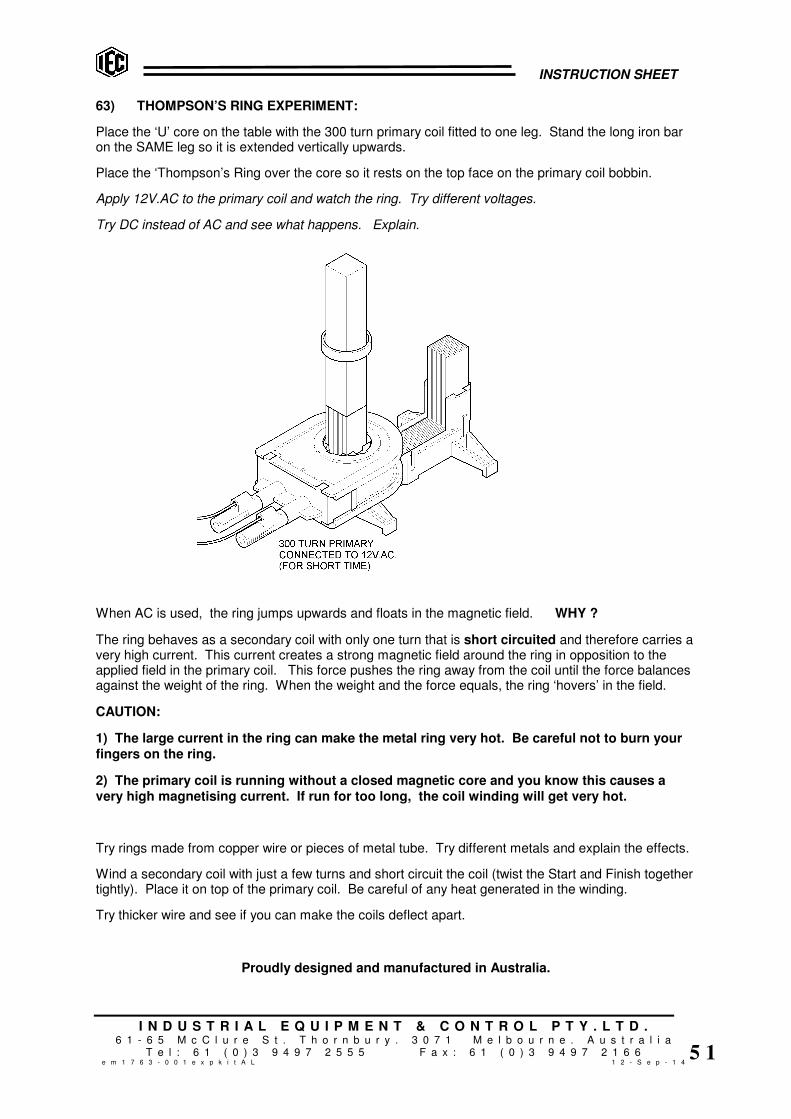
INSTRUCTION SHEET
I N D U S T R I A L E Q U I P M E N T & C O N T R O L P T Y . L T D .6 1 - 6 5 M c C l u r e S t . T h o r n b u r y . 3 0 7 1 M e l b o u r n e . A u s t r a l i a
T e l : 6 1 ( 0 ) 3 9 4 9 7 2 5 5 5 F a x : 6 1 ( 0 ) 3 9 4 9 7 2 1 6 6e m 1 7 6 3 - 0 0 1 e x p k i t A L 1 2 - S e p - 1 4
5 1
63) THOMPSON’S RING EXPERIMENT:
Place the ‘U’ core on the table with the 300 turn primary coil fitted to one leg. Stand the long iron baron the SAME leg so it is extended vertically upwards.
Place the ‘Thompson’s Ring over the core so it rests on the top face on the primary coil bobbin.
Apply 12V.AC to the primary coil and watch the ring. Try different voltages.
Try DC instead of AC and see what happens. Explain.
When AC is used, the ring jumps upwards and floats in the magnetic field. WHY ?
The ring behaves as a secondary coil with only one turn that is short circuited and therefore carries avery high current. This current creates a strong magnetic field around the ring in opposition to theapplied field in the primary coil. This force pushes the ring away from the coil until the force balancesagainst the weight of the ring. When the weight and the force equals, the ring ‘hovers’ in the field.
CAUTION:
1) The large current in the ring can make the metal ring very hot. Be careful not to burn yourfingers on the ring.
2) The primary coil is running without a closed magnetic core and you know this causes avery high magnetising current. If run for too long, the coil winding will get very hot.
Try rings made from copper wire or pieces of metal tube. Try different metals and explain the effects.
Wind a secondary coil with just a few turns and short circuit the coil (twist the Start and Finish togethertightly). Place it on top of the primary coil. Be careful of any heat generated in the winding.
Try thicker wire and see if you can make the coils deflect apart.
Proudly designed and manufactured in Australia.

INSTRUCTION SHEET
I N D U S T R I A L E Q U I P M E N T & C O N T R O L P T Y . L T D .6 1 - 6 5 M c C l u r e S t . T h o r n b u r y . 3 0 7 1 M e l b o u r n e . A u s t r a l i a
T e l : 6 1 ( 0 ) 3 9 4 9 7 2 5 5 5 F a x : 6 1 ( 0 ) 3 9 4 9 7 2 1 6 6e m 1 7 6 3 - 0 0 1 e x p k i t A L 1 2 - S e p - 1 4
5 2
EXPERIMENT NOTES

INSTRUCTION SHEET
I N D U S T R I A L E Q U I P M E N T & C O N T R O L P T Y . L T D .6 1 - 6 5 M c C l u r e S t . T h o r n b u r y . 3 0 7 1 M e l b o u r n e . A u s t r a l i a
T e l : 6 1 ( 0 ) 3 9 4 9 7 2 5 5 5 F a x : 6 1 ( 0 ) 3 9 4 9 7 2 1 6 6e m 1 7 6 3 - 0 0 1 e x p k i t A L 1 2 - S e p - 1 4
5 3
EXPERIMENT NOTES

INSTRUCTION SHEET
I N D U S T R I A L E Q U I P M E N T & C O N T R O L P T Y . L T D .6 1 - 6 5 M c C l u r e S t . T h o r n b u r y . 3 0 7 1 M e l b o u r n e . A u s t r a l i a
T e l : 6 1 ( 0 ) 3 9 4 9 7 2 5 5 5 F a x : 6 1 ( 0 ) 3 9 4 9 7 2 1 6 6e m 1 7 6 3 - 0 0 1 e x p k i t A L 1 2 - S e p - 1 4
5 4
EXPERIMENT NOTES

INSTRUCTION SHEET
I N D U S T R I A L E Q U I P M E N T & C O N T R O L P T Y . L T D .6 1 - 6 5 M c C l u r e S t . T h o r n b u r y . 3 0 7 1 M e l b o u r n e . A u s t r a l i a
T e l : 6 1 ( 0 ) 3 9 4 9 7 2 5 5 5 F a x : 6 1 ( 0 ) 3 9 4 9 7 2 1 6 6e m 1 7 6 3 - 0 0 1 e x p k i t A L 1 2 - S e p - 1 4
5 5
EXPERIMENT NOTES