
ELECTRICITY: Current Electricity Currents Circuits: Series and Parallel Generating Electricity Light...
16
ELECTRICITY: Current Electricity Currents Circuits: Series and Parallel Generating Electricity Light Bulb
-
Upload
blaze-atkins -
Category
Documents
-
view
234 -
download
0
Transcript of ELECTRICITY: Current Electricity Currents Circuits: Series and Parallel Generating Electricity Light...
ELECTRICITY:Current Electricity
Currents
Circuits: Series and Parallel
Generating Electricity
Light Bulb
CURRENT ELECTRICITY• Current electricity is flow of electric charge. The electric
charge in a current is carried by minute particles called electrons that orbit the nuclei of atoms.
• Each electron carries a small electric charge. When a stream of electrons moves from atom to atom—for example, inside a copper wire—the flow of the charge they carry is called electric current.
• Batteries and generators are devices that produce electric current to power lights and other appliances.
• Electric currents also occur in nature—lightning being a dramatic example.
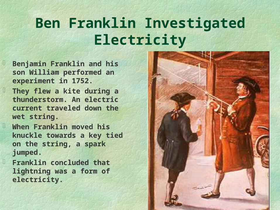
Ben Franklin Investigated Electricity
Benjamin Franklin and his son William performed an experiment in 1752.
They flew a kite during a thunderstorm. An electric current traveled down the wet string.
When Franklin moved his knuckle towards a key tied on the string, a spark jumped.
Franklin concluded that lightning was a form of electricity.
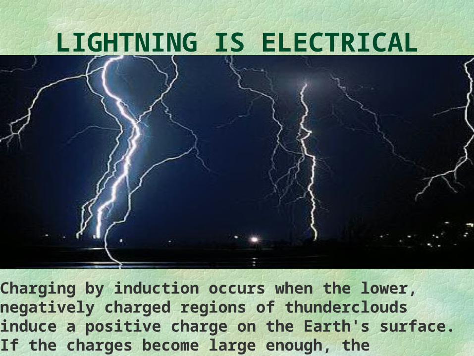
LIGHTNING IS ELECTRICAL
Charging by induction occurs when the lower, negatively charged regions of thunderclouds induce a positive charge on the Earth's surface. If the charges become large enough, the resistance of the air is overcome and lightning occurs.
CURRENT FLOW• Electric currents flow because atoms and molecules contain two
types of electrical charge, positive and negative, and these opposite charges attract each other.
• If there is a difference in the overall charge of atoms between two points—for example, between two ends of a wire—the negatively charged electrons will flow toward the positively charged end of the wire, creating electric current.
• Direct current (DC) is the flow of electricity in one direction. • Alternating current (AC) intermittently reverses direction
because of the way it is generated.
CIRCUITS: A Pathway for Moving Electrons
When the terminals of a battery are connected with a conductor an electric circuit is produced.
By means of chemical reactions within the battery, a potential difference is created between the terminals, and electrons flow in the conductor in one direction, away from the negative terminal toward the positive.
The 19th-century German physicist George Simon Ohm showed that the current in such a circuit was directly related to the voltage of the battery but noted that the amount of current also depended on the nature of the conductor.
Different kinds of conductors differed in the degree to which they resisted movement of electrons with a given voltage. He defined the resistance of a conductor as the ratio of the potential difference across the conductor (in volts) to the current (in amperes) through the conductor.
CIRCUIT DIAGRAMS
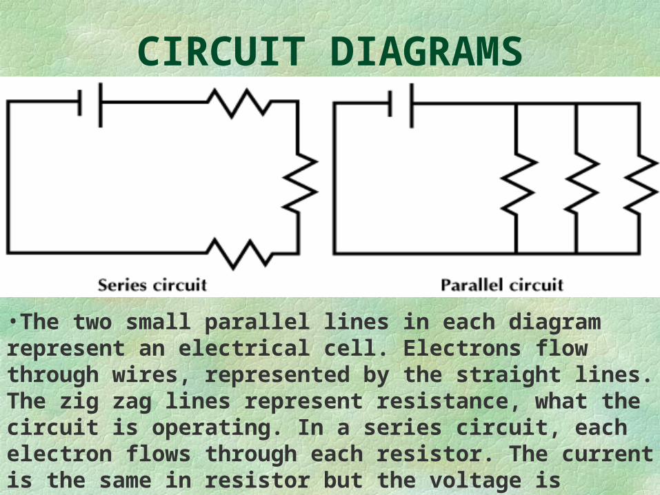
•The two small parallel lines in each diagram represent an electrical cell. Electrons flow through wires, represented by the straight lines. The zig zag lines represent resistance, what the circuit is operating. In a series circuit, each electron flows through each resistor. The current is the same in resistor but the voltage is reduced. •In a parallel circuit, the voltage is the same across each resistor, but the current can be different.
MAGNETIC FIELDS and CURRENTS
The movement of a compass needle, near a conductor through which a current is flowing, indicates the presence of a magnetic field around the conductor.
When currents flow through two parallel conductors, the magnetic fields of the conductors attract each other when the current flow is in the same direction in both conductors, and repel each other when the flows are in opposite directions.
The magnetic field caused by the current in a single loop or wire is such that if the loop is suspended near the earth, it will behave like a magnet or compass needle and swing until the wire of the loop is perpendicular to a line running from the north and south magnetic poles of the earth.
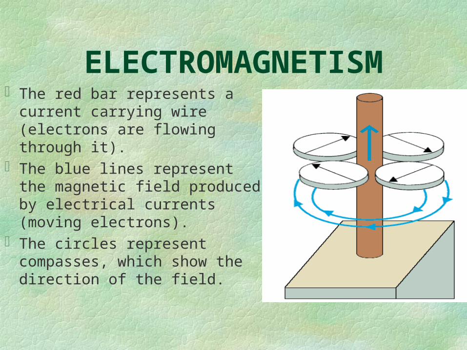
ELECTROMAGNETISMThe red bar represents a current
carrying wire (electrons are flowing through it).
The blue lines represent the magnetic field produced by electrical currents (moving electrons).
The circles represent compasses, which show the direction of the field.
GENERATING ELECTRICITY
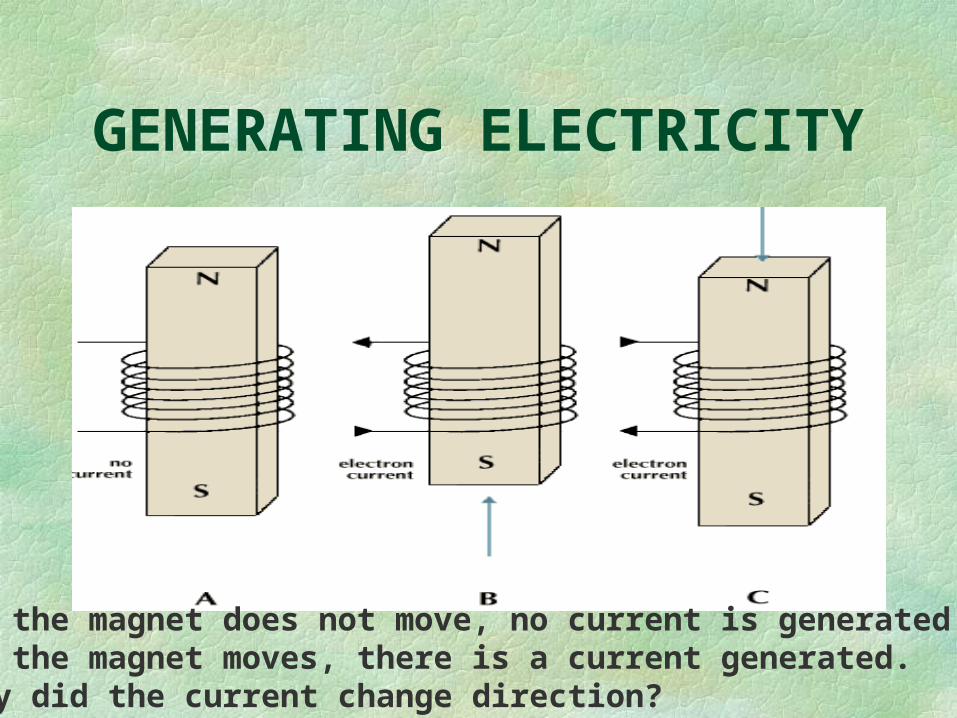
A. If the magnet does not move, no current is generated. B. If the magnet moves, there is a current generated.C. Why did the current change direction?
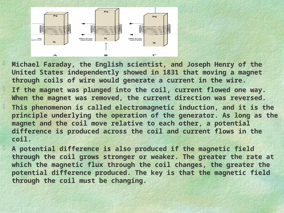
Michael Faraday, the English scientist, and Joseph Henry of the United States independently showed in 1831 that moving a magnet through coils of wire would generate a current in the wire.
If the magnet was plunged into the coil, current flowed one way. When the magnet was removed, the current direction was reversed.
This phenomenon is called electromagnetic induction, and it is the principle underlying the operation of the generator. As long as the magnet and the coil move relative to each other, a potential difference is produced across the coil and current flows in the coil.
A potential difference is also produced if the magnetic field through the coil grows stronger or weaker. The greater the rate at which the magnetic flux through the coil changes, the greater the potential difference produced. The key is that the magnetic field through the coil must be changing.
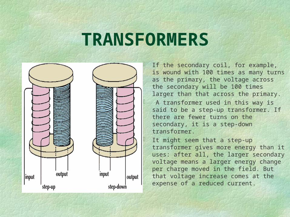
TRANSFORMERS If the secondary coil, for example, is wound
with 100 times as many turns as the primary, the voltage across the secondary will be 100 times larger than that across the primary.
A transformer used in this way is said to be a step-up transformer. If there are fewer turns on the secondary, it is a step-down transformer.
It might seem that a step-up transformer gives more energy than it uses: after all, the larger secondary voltage means a larger energy change per charge moved in the field. But that voltage increase comes at the expense of a reduced current.
TRANSFORMERS
A simple transformer consists of a coil of wire fed by a voltage source such as a generator. The coil is wound around one side of an iron frame. This is the primary coil. The other side of the iron frame is wound with another coil, the secondary, that feeds electricity to a separate circuit.
As alternating current from the generator flows in the primary coil, the magnetic field in that coil strengthens, weakens, and then reverses direction as the alternating current changes. The iron core intensifies these magnetic-field changes.
As the magnetic field in the secondary coil changes with time, electric charges in the secondary are deflected and current is produced. The alternating voltage produced in the secondary depends on the relative
number of turns in the secondary compared to the primary coil.
TRANSFORMERS The action of a transformer makes possible the economical
transmission of electric power over long distances. If 200,000 watts of power is supplied to a power line, it
may be equally well supplied by a potential of 200,000 V and a current of 1 amp or by a potential of 2000 V and a current of 100 amp, because power is equal to the product of voltage and current.
The power lost in the line through heating is equal to the square of the current times the resistance. Thus, if the resistance of the line is 10 ohms, the loss on the 200,000 V line will be 10 watts, whereas the loss on the 2000 V line will be 100,000 watts, or half the available power.
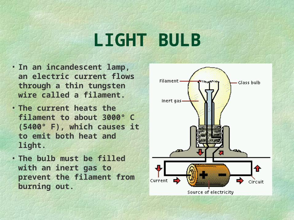
LIGHT BULB• In an incandescent lamp,
an electric current flows through a thin tungsten wire called a filament.
• The current heats the filament to about 3000° C (5400° F), which causes it to emit both heat and light.
• The bulb must be filled with an inert gas to prevent the filament from burning out.
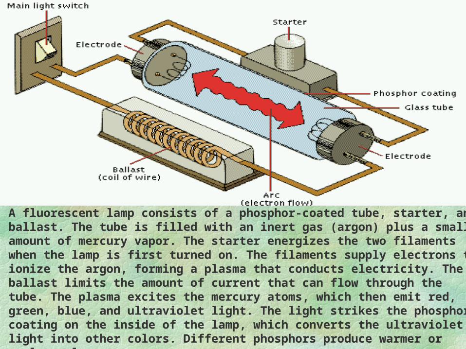
A fluorescent lamp consists of a phosphor-coated tube, starter, and ballast. The tube is filled with an inert gas (argon) plus a small amount of mercury vapor. The starter energizes the two filaments when the lamp is first turned on. The filaments supply electrons to ionize the argon, forming a plasma that conducts electricity. The ballast limits the amount of current that can flow through the tube. The plasma excites the mercury atoms, which then emit red, green, blue, and ultraviolet light. The light strikes the phosphor coating on the inside of the lamp, which converts the ultraviolet light into other colors. Different phosphors produce warmer or cooler colors.


![L 28 Electricity and Magnetism [6] magnetism Faraday’s Law of Electromagnetic Induction –induced currents –electric generator –eddy currents Electromagnetic.](https://static.fdocuments.us/doc/165x107/56649d035503460f949d6537/l-28-electricity-and-magnetism-6-magnetism-faradays-law-of-electromagnetic.jpg)


![L 28 Electricity and Magnetism [6] magnetism Faradays Law of Electromagnetic Induction induced currents electric generator eddy currents Electromagnetic.](https://static.fdocuments.us/doc/165x107/5a4d1b7c7f8b9ab0599b95a1/l-28-electricity-and-magnetism-6-magnetism-faradays-law-of-electromagnetic-induction.jpg)


