ELECTRICALSAFETYTESTERS - elsinco · Hipot and Insulation Resistance Tester High-End...
12
ELECTRICAL SAFETY TESTERS Wings for Your Projects. APPLICATION NOTE Four Principal Tests for Evaluating the Safety of Electrical and Electronic Products
Transcript of ELECTRICALSAFETYTESTERS - elsinco · Hipot and Insulation Resistance Tester High-End...

ELECTRICAL SAFETY TESTERS
Wings for Your Projects.
APPLICATION NOTE
Four Principal Tests for
Evaluating the Safety
of Electrical and Electronic Products
Hipot and Insulation Resistance Tester
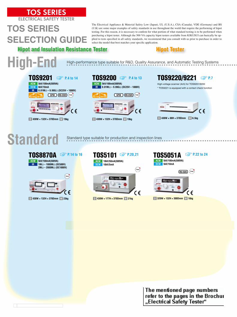
High-End High-performance type suitable for R&D, Quality Assurance, and Automatic Testing Systems
TOS92015kV/100mA(500VA)ACW6kV/10mADCW0.01MW – 9.99GW (DC25V – 1000V)IR
19kgWD 430W × 132H × 370Dmm
Rise Time Fall TimeGPIB RS-232C Timer
P.4 to 14 TOS92005kV/100mA(500VA)ACW0.01MW – 9.99GW (DC25V – 1000V)IR
GPIB RS-232C
19kgWD 430W × 132H × 370Dmm
Rise Time Fall TimeTimer
TOS9220/9221
6.5kgWD 430W × 88H × 370Dmm
P.7
StandardTOS8870A
5kV/100mA(500VA)ACW1MW – 1000MW (DC500V)2MW – 2000MW (DC1000V)
IR
23kgWD 430W × 132H × 370Dmm
Timer
P.14 to 16 TOS510110kV/50mA(500VA)ACW10kV/5mADCW
21kgWD 430W × 177H × 370Dmm
Timer
P.20,21 TOS5051A5kV/100mA(500VA)ACW5kV/10mADCW
RS-232C
16kgWD 320W × 132H × 300Dmm
Timer
P.22 to 24
W
High-voltage scanner (4ch) for TOS9201/9200* TOS9221 is equipped with a contact check function
Hipot Tester
Standard type suitable for production and inspection lines
Low-cost type most suitable for plants/factories producing in Asian markets
TOS SERIESSELECTION GUIDE
The Electrical Appliance & Material Safety Low (Japan), UL (U.S.A.), CSA (Canada), VDE (Germany) and BS (U.K) are some major examples of safety standards in use throughout the world that require the performing of hipot testing. For this reason, it is necessary to confirm for what portion of what standard testing is to be performed when purchasing a hipot tester. Although the 500 VA capacity hipot testers available from KIKUSUI can basically be ap-plied to tests specified in all safety standards, we recommend that you consult with us prior to purchase in order to select the model that best matches your specific application.
TOS SERIESELECTRICAL SAFETY TESTER
P.4 to 13
Renate
Stempel
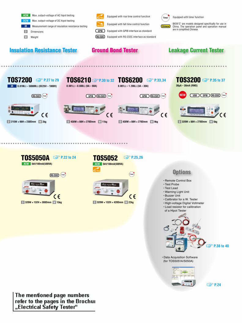
P.27 to 29
2kgWD 215W × 66H × 230Dmm
RS-232C Timer
TOS72000.01MW – 5000MW (DC25V – 1000V)IR
TOS62100.001W – 0.600W (6A – 60A)
11kgWD 430W × 88H × 270Dmm
GPIB RS-232C Timer
P.30 to 32
5kgWD 320W × 88H × 270Dmm
TOS320030µA – 30mA (RMS)
P.35 to 37TOS62000.001W – 1.200W (3A – 30A)
9kgWD 430W × 88H × 270Dmm
GPIB RS-232C Timer
P.33,34
GPIB RS-232C TimerUSB
Rise Time Equipped with rise time control function
Fall Time Equipped with fall time control function
GPIB Equipped with GPIB interface as standard
RS-232C Equipped with RS-232C interface as standard
DimensionsD
WeightW
ACW
IR
DCWEquipped with timer functionTimer
Chinese
TOS5050A P.22 to 24
5kV/100mA(500VA)ACW
15kgWD 320W × 132H × 300Dmm
RS-232C Timer
TOS5052 P.25,26
5kV/100mA(500VA)ACWACW
22kgWD 320W × 132H × 420Dmm
Rise Time
Timer
• Data Acquisition Software (for TOS5051A/5050A)
P.24
• Remote Control Box• Test Probe• Test Lead• Warning Light Unit• Buzzer Unit• Calibrator for a W. Tester• High-voltage Digital Voltmeter• Load resistor for calibration of a Hipot Tester
P.38 to 40
Insulation Resistance Tester Ground Bond Tester
Options
8XXX'C' are models designed specifically for use in China. The operation panel and operation manual are in simplified Chinese.
Measurement range of insulation resistance testing
Max. output-voltage of AC hipot testing
Max. output-voltage of DC hipot testing
Leakage Current Tester
Renate
Stempel
A Glossary
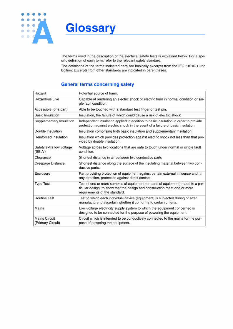
The terms used in the description of the electrical safety tests is explained below. For a spe-cific definition of each term, refer to the relevant safety standard.
The definitions of the terms indicated here are basically excerpts from the IEC 61010-1 2ndEdition. Excerpts from other standards are indicated in parentheses.
General terms concerning safety
Hazard Potential source of harm.
Hazardous Live Capable of rendering an electric shock or electric burn in normal condition or sin-gle fault condition.
Accessible (of a part) Able to be touched with a standard test finger or test pin.
Basic Insulation Insulation, the failure of which could cause a risk of electric shock.
Supplementary Insulation Independent insulation applied in addition to basic insulation in order to provide protection against electric shock in the event of a failure of basic insulation.
Double Insulation Insulation comprising both basic insulation and supplementary insulation.
Reinforced Insulation Insulation which provides protection against electric shock not less than that pro-vided by double insulation.
Safety extra low voltage (SELV)
Voltage across two locations that are safe to touch under normal or single fault condition.
Clearance Shortest distance in air between two conductive parts
Creepage Distance Shortest distance along the surface of the insulating material between two con-ductive parts.
Enclosure Part providing protection of equipment against certain external influence and, in any direction, protection against direct contact.
Type Test Test of one or more samples of equipment (or parts of equipment) made to a par-ticular design, to show that the design and construction meet one or more requirements of the standard.
Routine Test Test to which each individual device (equipment) is subjected during or after manufacture to ascertain whether it conforms to certain criteria.
Mains Low-voltage electricity supply system to which the equipment concerned is designed to be connected for the purpose of powering the equipment.
Mains Circuit (Primary Circuit)
Circuit which is intended to be conductively connected to the mains for the pur-pose of powering the equipment.
Glossary
Appx
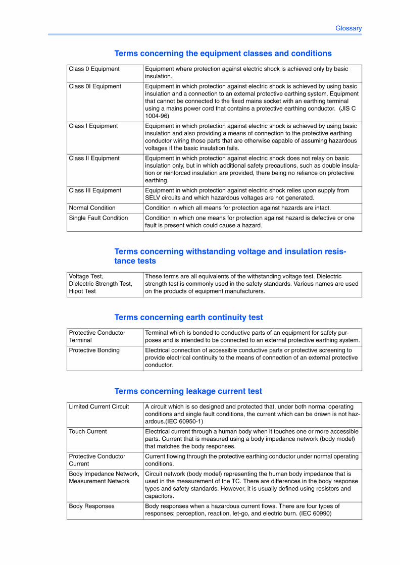
Terms concerning the equipment classes and conditions
Terms concerning withstanding voltage and insulation resis-tance tests
Terms concerning earth continuity test
Terms concerning leakage current test
Class 0 Equipment Equipment where protection against electric shock is achieved only by basic insulation.
Class 0I Equipment Equipment in which protection against electric shock is achieved by using basic insulation and a connection to an external protective earthing system. Equipment that cannot be connected to the fixed mains socket with an earthing terminal using a mains power cord that contains a protective earthing conductor. (JIS C 1004-96)
Class I Equipment Equipment in which protection against electric shock is achieved by using basic insulation and also providing a means of connection to the protective earthing conductor wiring those parts that are otherwise capable of assuming hazardous voltages if the basic insulation fails.
Class II Equipment Equipment in which protection against electric shock does not relay on basic insulation only, but in which additional safety precautions, such as double insula-tion or reinforced insulation are provided, there being no reliance on protective earthing.
Class III Equipment Equipment in which protection against electric shock relies upon supply from SELV circuits and which hazardous voltages are not generated.
Normal Condition Condition in which all means for protection against hazards are intact.
Single Fault Condition Condition in which one means for protection against hazard is defective or one fault is present which could cause a hazard.
Voltage Test, Dielectric Strength Test, Hipot Test
These terms are all equivalents of the withstanding voltage test. Dielectric strength test is commonly used in the safety standards. Various names are used on the products of equipment manufacturers.
Protective Conductor Terminal
Terminal which is bonded to conductive parts of an equipment for safety pur-poses and is intended to be connected to an external protective earthing system.
Protective Bonding Electrical connection of accessible conductive parts or protective screening to provide electrical continuity to the means of connection of an external protective conductor.
Limited Current Circuit A circuit which is so designed and protected that, under both normal operating conditions and single fault conditions, the current which can be drawn is not haz-ardous.(IEC 60950-1)
Touch Current Electrical current through a human body when it touches one or more accessible parts. Current that is measured using a body impedance network (body model) that matches the body responses.
Protective Conductor Current
Current flowing through the protective earthing conductor under normal operating conditions.
Body Impedance Network, Measurement Network
Circuit network (body model) representing the human body impedance that is used in the measurement of the TC. There are differences in the body response types and safety standards. However, it is usually defined using resistors and capacitors.
Body Responses Body responses when a hazardous current flows. There are four types of responses: perception, reaction, let-go, and electric burn. (IEC 60990)
B Four Principal Tests for Evaluating the Safety of Electrical and Electronic Products
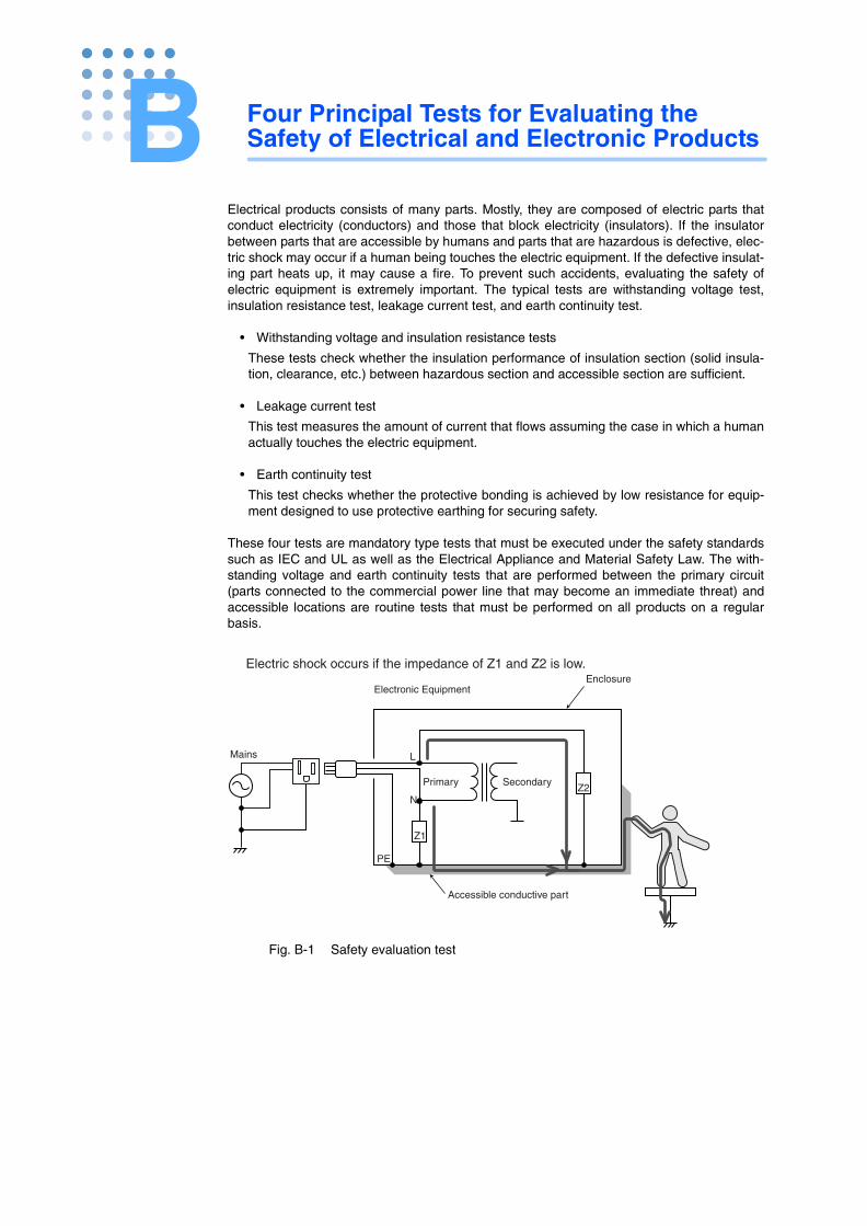
Electrical products consists of many parts. Mostly, they are composed of electric parts thatconduct electricity (conductors) and those that block electricity (insulators). If the insulatorbetween parts that are accessible by humans and parts that are hazardous is defective, elec-tric shock may occur if a human being touches the electric equipment. If the defective insulat-ing part heats up, it may cause a fire. To prevent such accidents, evaluating the safety ofelectric equipment is extremely important. The typical tests are withstanding voltage test,insulation resistance test, leakage current test, and earth continuity test.
• Withstanding voltage and insulation resistance tests
These tests check whether the insulation performance of insulation section (solid insula-tion, clearance, etc.) between hazardous section and accessible section are sufficient.
• Leakage current test
This test measures the amount of current that flows assuming the case in which a humanactually touches the electric equipment.
• Earth continuity test
This test checks whether the protective bonding is achieved by low resistance for equip-ment designed to use protective earthing for securing safety.
These four tests are mandatory type tests that must be executed under the safety standardssuch as IEC and UL as well as the Electrical Appliance and Material Safety Law. The with-standing voltage and earth continuity tests that are performed between the primary circuit(parts connected to the commercial power line that may become an immediate threat) andaccessible locations are routine tests that must be performed on all products on a regularbasis.
Fig. B-1 Safety evaluation test
N
L
PE
Z1
Z2
EnclosureElectronic Equipment
SecondaryPrimary
Mains
Accessible conductive part
Electric shock occurs if the impedance of Z1 and Z2 is low.
Four Principal Tests for Evaluating the Safety of Electrical and Electronic Products
Withstanding Voltage Test
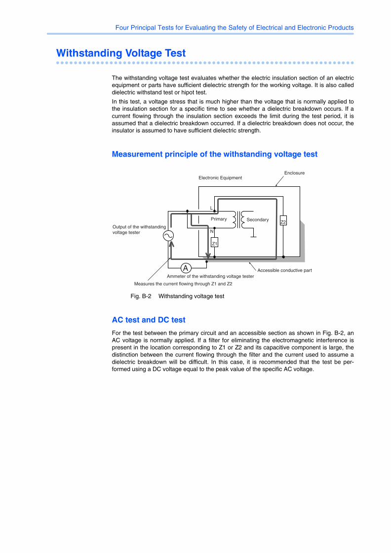
The withstanding voltage test evaluates whether the electric insulation section of an electricequipment or parts have sufficient dielectric strength for the working voltage. It is also calleddielectric withstand test or hipot test.
In this test, a voltage stress that is much higher than the voltage that is normally applied tothe insulation section for a specific time to see whether a dielectric breakdown occurs. If acurrent flowing through the insulation section exceeds the limit during the test period, it isassumed that a dielectric breakdown occurred. If a dielectric breakdown does not occur, theinsulator is assumed to have sufficient dielectric strength.
Measurement principle of the withstanding voltage test
Fig. B-2 Withstanding voltage test
AC test and DC test
For the test between the primary circuit and an accessible section as shown in Fig. B-2, anAC voltage is normally applied. If a filter for eliminating the electromagnetic interference ispresent in the location corresponding to Z1 or Z2 and its capacitive component is large, thedistinction between the current flowing through the filter and the current used to assume adielectric breakdown will be difficult. In this case, it is recommended that the test be per-formed using a DC voltage equal to the peak value of the specific AC voltage.
N
L
Z1
Z2
EnclosureElectronic Equipment
SecondaryPrimary
Accessible conductive partA
Output of the withstanding voltage tester
Ammeter of the withstanding voltage tester
Measures the current flowing through Z1 and Z2
Four Principal Tests for Evaluating the Safety of Electrical and Electronic Products
Insulation Resistance Test
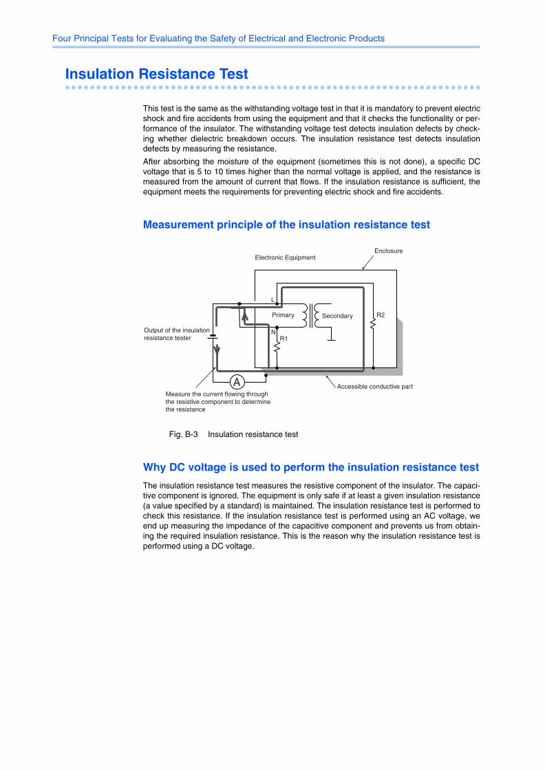
This test is the same as the withstanding voltage test in that it is mandatory to prevent electricshock and fire accidents from using the equipment and that it checks the functionality or per-formance of the insulator. The withstanding voltage test detects insulation defects by check-ing whether dielectric breakdown occurs. The insulation resistance test detects insulationdefects by measuring the resistance.
After absorbing the moisture of the equipment (sometimes this is not done), a specific DCvoltage that is 5 to 10 times higher than the normal voltage is applied, and the resistance ismeasured from the amount of current that flows. If the insulation resistance is sufficient, theequipment meets the requirements for preventing electric shock and fire accidents.
Measurement principle of the insulation resistance test
Fig. B-3 Insulation resistance test
Why DC voltage is used to perform the insulation resistance test
The insulation resistance test measures the resistive component of the insulator. The capaci-tive component is ignored. The equipment is only safe if at least a given insulation resistance(a value specified by a standard) is maintained. The insulation resistance test is performed tocheck this resistance. If the insulation resistance test is performed using an AC voltage, weend up measuring the impedance of the capacitive component and prevents us from obtain-ing the required insulation resistance. This is the reason why the insulation resistance test isperformed using a DC voltage.
N
L
R2
R1
EnclosureElectronic Equipment
SecondaryPrimary
Accessible conductive partA
Output of the insulation resistance tester
Measure the current flowing through the resistive component to determine the resistance
Four Principal Tests for Evaluating the Safety of Electrical and Electronic Products
Earth Continuity Test
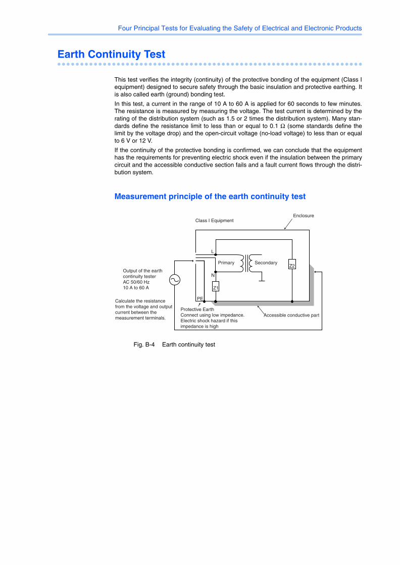
This test verifies the integrity (continuity) of the protective bonding of the equipment (Class Iequipment) designed to secure safety through the basic insulation and protective earthing. Itis also called earth (ground) bonding test.
In this test, a current in the range of 10 A to 60 A is applied for 60 seconds to few minutes.The resistance is measured by measuring the voltage. The test current is determined by therating of the distribution system (such as 1.5 or 2 times the distribution system). Many stan-dards define the resistance limit to less than or equal to 0.1 Ω (some standards define thelimit by the voltage drop) and the open-circuit voltage (no-load voltage) to less than or equalto 6 V or 12 V.
If the continuity of the protective bonding is confirmed, we can conclude that the equipmenthas the requirements for preventing electric shock even if the insulation between the primarycircuit and the accessible conductive section fails and a fault current flows through the distri-bution system.
Measurement principle of the earth continuity test
Fig. B-4 Earth continuity test
N
PE
L
Z1
Z2
EnclosureClass I Equipment
SecondaryPrimary
Accessible conductive partProtective EarthConnect using low impedance.Electric shock hazard if this impedance is high
Output of the earth continuity testerAC 50/60 Hz10 A to 60 A
Calculate the resistance from the voltage and output current between the measurement terminals.
Four Principal Tests for Evaluating the Safety of Electrical and Electronic Products
Leakage Current Test
The term Touch Current and Protective Conductor Current are defined in the latest interna-tional standard, IEC 60990. These terms were previously referred to as Leakage Current.
• Touch Current (TC)
Current that flows when a human body touches the equipment. If the measured TC doesnot exceed the value hazardous to a human body as defined by a safety standard or thelike, the equipment meets the requirements for preventing electric shock.
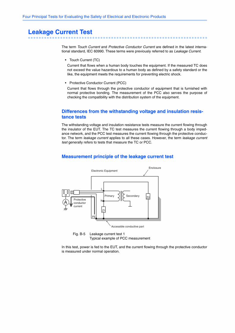
• Protective Conductor Current (PCC)
Current that flows through the protective conductor of equipment that is furnished withnormal protective bonding. The measurement of the PCC also serves the purpose ofchecking the compatibility with the distribution system of the equipment.
Differences from the withstanding voltage and insulation resis-tance tests
The withstanding voltage and insulation resistance tests measure the current flowing throughthe insulator of the EUT. The TC test measures the current flowing through a body imped-ance network, and the PCC test measures the current flowing through the protective conduc-tor. The term leakage current applies to all these cases. However, the term leakage currenttest generally refers to tests that measure the TC or PCC.
Measurement principle of the leakage current test
Fig. B-5 Leakage current test 1Typical example of PCC measurement
In this test, power is fed to the EUT, and the current flowing through the protective conductoris measured under normal operation.
N
L
PE
Z1
Z2
EnclosureElectronic Equipment
SecondaryPrimary
Accessible conductive part
Protective conductor current
A
Four Principal Tests for Evaluating the Safety of Electrical and Electronic Products
Appx
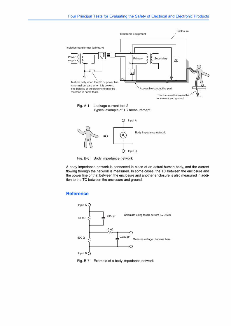
Fig. A-1 Leakage current test 2Typical example of TC measurement
Fig. B-6 Body impedance network
A body impedance network is connected in place of an actual human body, and the currentflowing through the network is measured. In some cases, the TC between the enclosure andthe power line or that between the enclosure and another enclosure is also measured in addi-tion to the TC between the enclosure and ground.
Reference
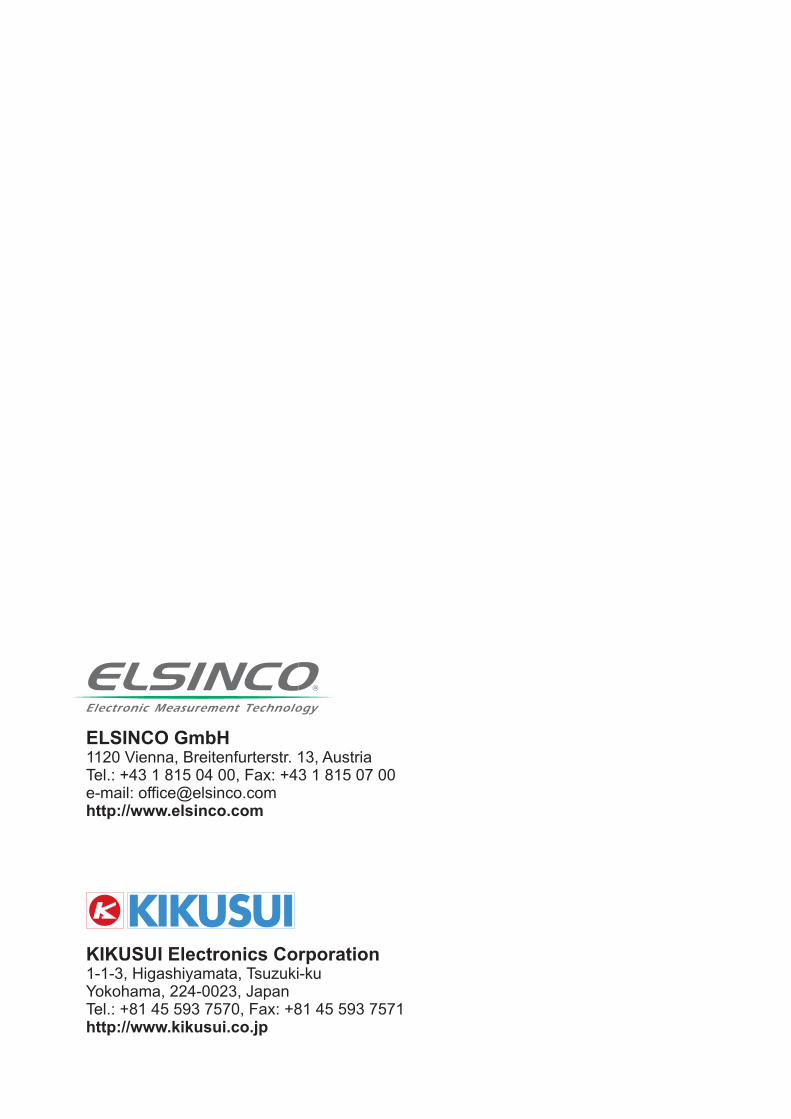
Fig. B-7 Example of a body impedance network
N
L
PE
Z1
Z2
EnclosureElectronic Equipment
SecondaryPrimaryPower supply
Accessible conductive part
Test not only when the PE or power line is normal but also when it is broken.The polarity of the power line may be reversed in some tests.
Isolation transformer (arbitrary)
Touch current between the enclosure and ground
A
Input A
Input B
Body impedance network
Input A
Input B
Measure voltage U across here
Calculate using touch current I = U/500 1.5 kΩ
500 Ω
10 kΩ
0.22 µF
0.022 µF
ELSINCO GmbH
1120 Vienna, Breitenfurterstr. 13, AustriaTel.: +43 1 815 04 00, Fax: +43 1 815 07 00e-mail: [email protected]://www.elsinco.com
KIKUSUI Electronics Corporation
1-1-3, Higashiyamata, Tsuzuki-kuYokohama, 224-0023, JapanTel.: +81 45 593 7570, Fax: +81 45 593 7571http://www.kikusui.co.jp