ELECTRICAL SERVICE REQUIREMENTS UNDERGROUND SERVICES…
31
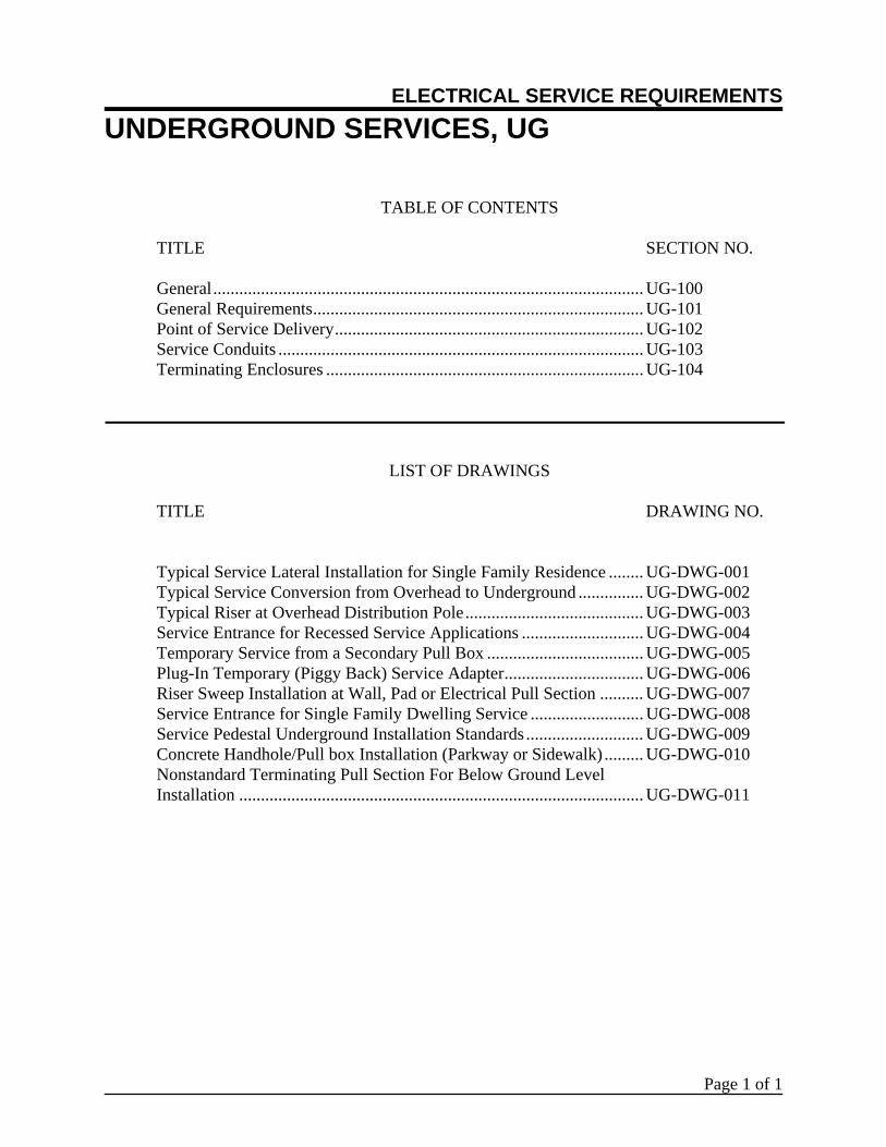
ELECTRICAL SERVICE REQUIREMENTS UNDERGROUND SERVICES, UG Page 1 of 1 TABLE OF CONTENTS TITLE SECTION NO. General ................................................................................................... UG-100 General Requirements............................................................................ UG-101 Point of Service Delivery ....................................................................... UG-102 Service Conduits .................................................................................... UG-103 Terminating Enclosures ......................................................................... UG-104 LIST OF DRAWINGS TITLE DRAWING NO. Typical Service Lateral Installation for Single Family Residence ........ UG-DWG-001 Typical Service Conversion from Overhead to Underground ............... UG-DWG-002 Typical Riser at Overhead Distribution Pole ......................................... UG-DWG-003 Service Entrance for Recessed Service Applications ............................ UG-DWG-004 Temporary Service from a Secondary Pull Box .................................... UG-DWG-005 Plug-In Temporary (Piggy Back) Service Adapter................................ UG-DWG-006 Riser Sweep Installation at Wall, Pad or Electrical Pull Section .......... UG-DWG-007 Service Entrance for Single Family Dwelling Service .......................... UG-DWG-008 Service Pedestal Underground Installation Standards ........................... UG-DWG-009 Concrete Handhole/Pull box Installation (Parkway or Sidewalk) ......... UG-DWG-010 Nonstandard Terminating Pull Section For Below Ground Level Installation ............................................................................................. UG-DWG-011
Transcript of ELECTRICAL SERVICE REQUIREMENTS UNDERGROUND SERVICES…
ELECTRICAL SERVICE REQUIREMENTS UNDERGROUND SERVICES, UG
Page 1 of 1
TABLE OF CONTENTS TITLE SECTION NO. General ................................................................................................... UG-100 General Requirements ............................................................................ UG-101 Point of Service Delivery ....................................................................... UG-102 Service Conduits .................................................................................... UG-103 Terminating Enclosures ......................................................................... UG-104
LIST OF DRAWINGS TITLE DRAWING NO. Typical Service Lateral Installation for Single Family Residence ........ UG-DWG-001 Typical Service Conversion from Overhead to Underground ............... UG-DWG-002 Typical Riser at Overhead Distribution Pole ......................................... UG-DWG-003 Service Entrance for Recessed Service Applications ............................ UG-DWG-004 Temporary Service from a Secondary Pull Box .................................... UG-DWG-005 Plug-In Temporary (Piggy Back) Service Adapter ................................ UG-DWG-006 Riser Sweep Installation at Wall, Pad or Electrical Pull Section .......... UG-DWG-007 Service Entrance for Single Family Dwelling Service .......................... UG-DWG-008 Service Pedestal Underground Installation Standards ........................... UG-DWG-009 Concrete Handhole/Pull box Installation (Parkway or Sidewalk) ......... UG-DWG-010 Nonstandard Terminating Pull Section For Below Ground Level Installation ............................................................................................. UG-DWG-011
GENERAL UG-100
Page 1 of 3
Underground Service Availability Overhead service will not be supplied to any buildings or premises in an area designated by GWP as an Underground District. In areas where both overhead and underground service facilities exist, GWP shall be consulted for determination of the type of service which will be supplied. In general, an underground service will be required when an underground stub-out is available at the property line. See GEN-105. In no case, shall a building be served with two different types of services. If a residential or multi-residential customer is upgrading an existing overhead electric service to 100A for safety reasons (room additions do not qualify), and is located within the underground district, the customer shall be exempted from converting to an underground service. These services may continue to be served from overhead system and no stub-downs or connection to the underground system is required. However, the panel must be upgraded and replaced with an overhead to underground panel. If the service is being upgraded to 100A or 200A, and the existing service conduit is undersized (2” or 2 ½”), special consideration must take place for the undersized service conduit to be utilized. A special letter must be signed by the customer to agree with conditions set forth by GWP. See UG-100 Page 3 of 3.
Single-Phase Service - 120/240 Volt The maximum service size for a single-phase, three-wire, 120/240V service is 400 amperes. For services larger than 400 amperes, an on-site transformer facility is required. See PRI Section.
GENERAL UG-100
Page 2 of 3
Three-Phase Service - 240 Volt The maximum service size for a three-phase, 240 volt, three-wire delta service is 400 amperes. For services larger than 400 amperes, an on-site transformer facility is required. See PRI Section. In order to avoid the purchase of unsuitable switchgear and/or improper utilization of this service type, close attention must be given to the following:
1. This is not a 4-wire service. No neutral is provided. A fourth service entrance conductor is required as a grounded conductor.
2. Only three-phase balanced loads can be applied to this service. No single-phase
load is allowed. 3. Service equipment (meter panels) must be labeled for three-phase, three-wire.
This must be stated on the manufacturer’s factory supplied label. 4. A bolted in bus link is needed in the metering transformer compartment for each
phase. 5. All service equipment must conform to Electrical Utility Service Equipment
Requirements Committee (EUSERC) requirements (some manufacturers do not make equipment that conforms to the above requirements).
6. Any questions about the above requirements should be addressed to your service
planner at (818) 548-3921.
Three-Phase Service - 120/240 Volts Four Wire Delta (if available) The maximum service size for a three-phase, four-wire 120/240V Delta service is 400 amperes.
GENERAL UG-100
Page 3 of 3
To: Glendale Water &Power Department, Electrical Services Division Subject: Residential Conduit Variance for Underground Electric Service Since my existing underground electrical service conduit does not meet Glendale Water & Power’s three inch diameter conduit standards, I, , the owner of the property located at am requesting to continue the use of my existing ______ inch electrical service conduit for the proposed upgrade of my existing service panel to _____amps.
I acknowledge that the following conditions must be adhered to by me and my contractor(s) before the Glendale Water & Power’s electric construction inspector will allow the permanent service cable to be installed. I understand also that Glendale Water & Power reserves the right not to accept any stage of the process below:
1. The existing cable must be successfully pulled out from the existing conduit(s) by Glendale Water
& Power work crews. 2. The existing empty service conduit(s) must pass a mandrel test which is performed by the
customer/contractor in the presence of a Glendale Water & Power Construction Inspector. Roto-rooting of conduit(s) to clear conduit problem(s) will not be allowed.
3. If the existing conduit(s) passes the mandrel test, the new service cable must be successfully pulled
into the existing conduit(s) by Glendale Water & Power work crews. 4. I understand that if the existing conduit(s) is of a type of material that does not meet Glendale
Water & Power’s current standards, then the existing underground conduit(s) cannot be used for the new service.
5. If the existing conduit system is exposed or at an improper depth, then I understand that I may be
required to make corrections that would bring the system up to current standards. I would also be responsible for maintaining the temporary electrical service to my house during the building of a new system if a temporary service installation cannot be provided and installed by Glendale Water & Power. I agree to comply with all of the above written conditions that may be required from me and my contractor(s), in order to provide my home with an electrical service which complies with current Glendale Water & Power’s Electric Construction Standards.
Signature: _______________________________ Dated: __________________________________
GENERAL REQUIREMENTS UG-101
Page 1 of 3
Safety Person Breaking into energized subterranean vaults, pull boxes or duct banks require the presence of a GWP safety person. To coordinate this work, contact the GWP Construction Inspector (818) 548-3920, 48 hours in advance.
Installation of Structures The customer is responsible for installations of service ducts and appurtenant structures for service from an overhead or underground line source, both on the customer’s premises and in public right-of-way.
Locations of Structures GWP’s approval is required in advance of construction for the locations and type of structures installed for GWP’s use.
Grounding All grounding materials shall be furnished and installed by the contractor. Contact GWP Customer Service Engineering for information on specific installations.
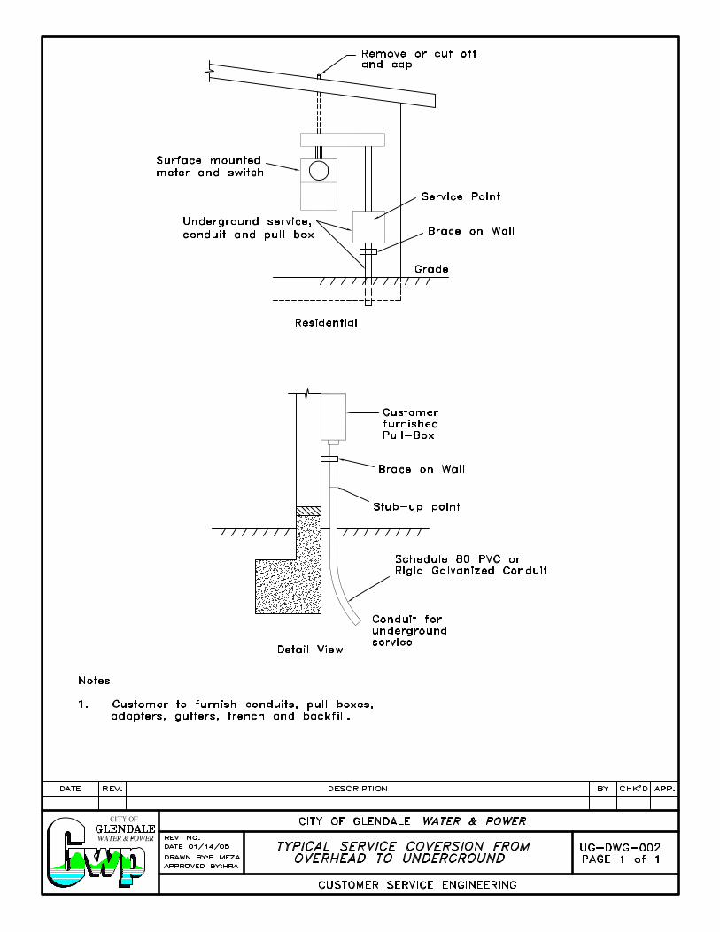
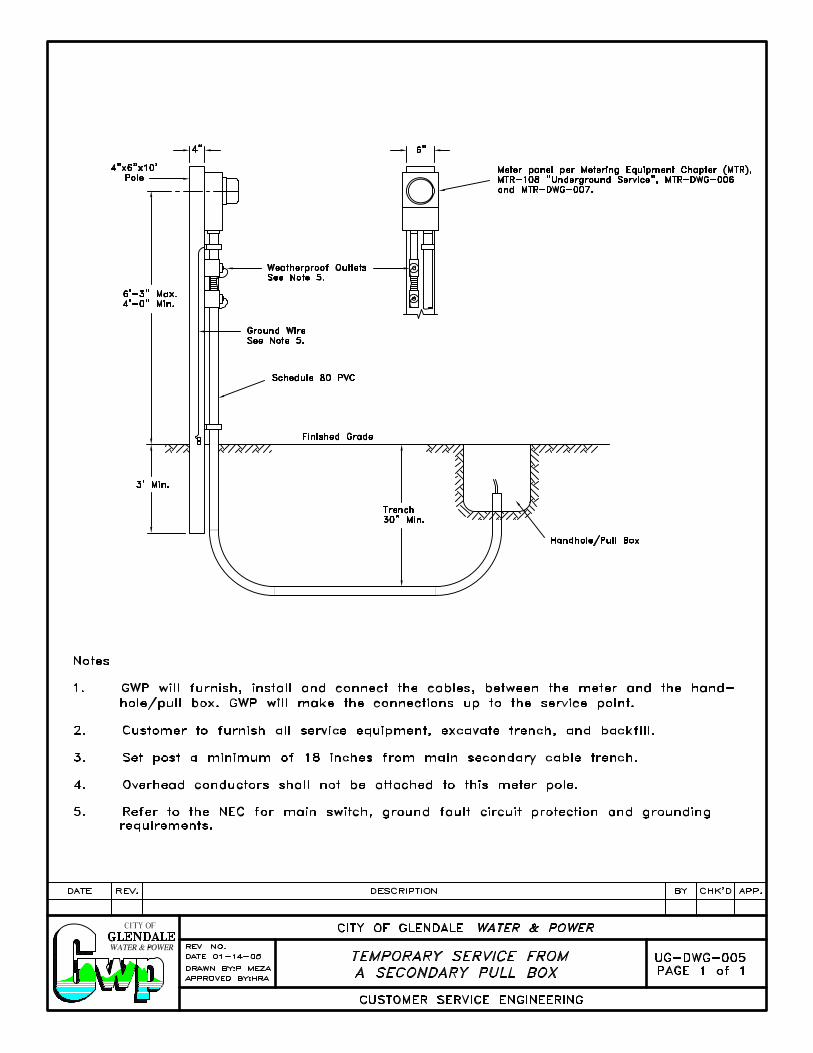
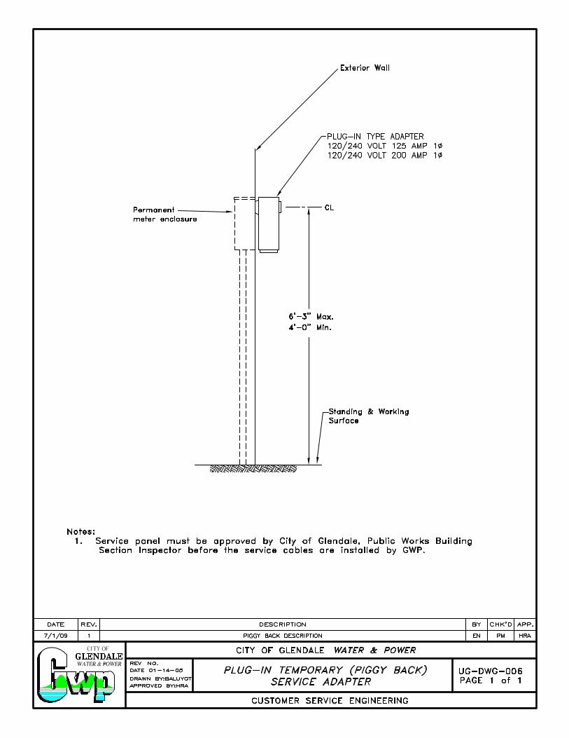
Temporary Service Connections A service connection for temporary use during construction may be made from an underground source provided the customer installs the necessary structures and facilities at the customer’s cost. To keep the temporary installation and removal costs to a minimum, the facilities for the permanent service should be completed to the fullest extent practicable. A temporary conduit may be installed from a permanent subterranean pull box at the end of the run or in the run of the permanent service conduit. This temporary conduit which connects to a suitable temporary metering shall be installed by the customer and the required conductors are installed by GWP. See UG-DWG-005 and UG-DWG-006 for typical temporary underground service connections. The customer shall pay the cost of installation and removal of temporary service connections and related equipment.
GENERAL REQUIREMENTS UG-101
Page 2 of 3
Underground Service from an Overhead or an Underground Source Any customer desiring the service conductors underground shall furnish and install at customer’s expense all conduits or ducts, subterranean pull boxes or vaults, and risers on poles, as required by GWP, and as specified in these requirements. GWP will determine the number of conduit runs and the size of conduits installed in each case. All secondary distribution subterranean pull boxes involve special requirements. Consult GWP for the special requirements. A distribution pull box is one that is intended for use by more than one customer.
Maintenance The customer shall maintain all conduits and substructures in private property and GWP will maintain all conduits and substructures in the public right-of-way.
Service Conductors GWP will, in all cases, determine the size, type and number of runs, of service conductors from GWP’s lines to the terminating enclosure.
Cost of Service Secondary Service - The customer shall pay to GWP the cost of all material and labor hours required to install the service. See GEN-104, Table 1 for a schedule of charges for Overhead, Underground, and Overhead to Underground Services.
Pre-construction Conference Materials and construction are subject to inspection and approval of GWP. Notify GWP’s Construction Inspector at (818) 548-3920, 48 hours in advance of construction for a pre-construction conference. Contractor must also secure GWP authorization prior to obtaining an excavation permit for any work in the public right-of-way.
Easement
Distribution conduit runs will require an easement to the City, whenever they cross private property, prior to electric service connection.
GENERAL REQUIREMENTS UG-101
Page 3 of 3
Excavation Permit When excavating in the public right-of-way, an excavation permit is required from City of Glendale, Public Works Department, Permit Services Center, telephone number (818) 548-3200, 633 E. Broadway, Room 101. Contractor shall notify Public Works Construction Inspector at (818) 548-3940, 48 hours in advance of the time when backfilling is to be done under this permit. The excavation permit shall be made available at the job site for review by the GWP Construction Inspector.
Resurfacing All necessary resurfacing in the public right-of-way is the total responsibility of the contractor, and must be to the satisfaction of the Public Works Inspector. All city property shall be restored to its original condition.
Existing Substructures The contractor shall verify all existing substructure information and dimensions in the public right-of-way. Any damage to these substructures will be the total responsibility of the contractor.
Field Change/Revisions/Plan Change If it is necessary to deviate from the approved substructure plan, the contractor shall duly notify the engineer, inspector or the authorized representative of GWP at (818) 548-3921 before implementing any changes. The engineer shall give a duly approved, revised written plan to the contractor which shall then become part of the approved plans. The contractor shall use the revised written plan when implementing a change/revision in the field.
Retaining Wall
Where vaults, pull-boxes, or street light bases are installed adjacent to an embankment, retaining walls shall be installed in accordance with the grading plan or as required by GWP Construction Inspector.
POINT OF SERVICE DELIVERY UG-102
Page 1 of 2
SINGLE POINT OF SERVICE DELIVERY PER BUILDING Normally only one point of service delivery will be established for any single or multiple occupancy building (including condominiums in common tenancy). All terminating enclosures for services for each of the types, phase and voltage classes of load to be served shall be grouped at this location. Exception: Where a building is more than 150 feet in length, additional points of service delivery may be established. Each such service point shall be metered separately from other service points. Where GWP owned transformers are to be installed on the customer’s premises, refer to the PRI section relative to service delivery.
SINGLE POINT OF SERVICE DELIVERY FOR EACH PREMISE Only one point of service delivery will be established for each lot or continuous premises on which one or more buildings are to be served. All terminating enclosures for services for each of the types and phase and voltage classes of load to be served shall be grouped at this location. In cases where single premises are abnormally extensive in area, consult with GWP Customer Service Engineering to determine how service will be provided.
POINT OF SERVICE DELIVERY UG-102
Page 2 of 2
LOCATION OF POINT OF SERVICE DELIVERY The location of each point of service delivery must be approved by GWP in advance of construction. All terminating enclosures at a point of service delivery shall comply with the detailed requirements of Location of Terminating Enclosures, see UG-104. The following requirements will apply:
1. Secondary Service (240 volts)
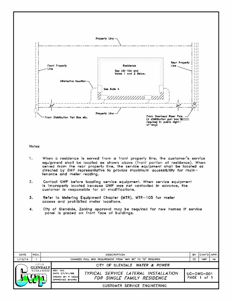
a. Where GWP installs underground service cables from its overhead or underground lines to a point of service delivery on or in a building or structure, the point of service delivery shall be at or immediately adjacent to the building wall nearest and facing (1) the point at which the service duct enters the premises (2) the pole from which the service originates; and shall be as near as practicable to the corner of such wall which is accessible with a minimum length of service duct. For meter locations, see MTR-105. The point of service delivery may be in a pull box provided it is in a permanently accessible location approved by GWP.
b. Where GWP installs service cables from its lines to a point of service delivery at which the terminating enclosure is a wall mounted pull box, or the pull section of an outdoor switchboard, its location shall be approved by GWP.
2. Primary Service (4.16kV or 12.47kV)
a. GWP will install the service cable in all high-voltage services in accordance
with the applicable provisions of its rules.
SERVICE CONDUIT(S) UG-103
Page 1 of 4
Service Conduit Installation The customer shall install any service duct in accordance with GWP’s standards.
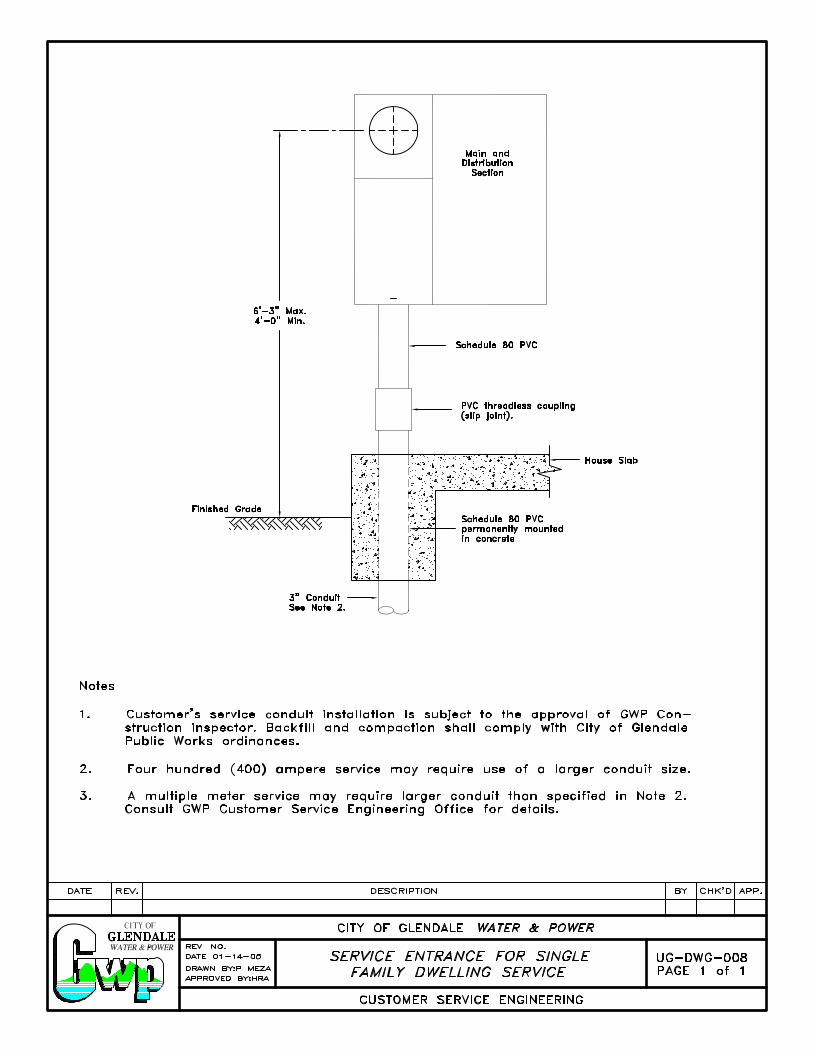
Size and Number of Conduit(s) Refer to GWP’s service spot for information relative to the minimum conduit size and number acceptable to GWP. A duct with 3-inch nominal inside diameter is the minimum acceptable size for pedestal services and residential services. Unless specified by GWP.
Service Conduit(s) Through Buildings When the customer’s terminating enclosure is within the building and GWP pulls cables to this point, the customer shall install a conduit encased in or under two inches of concrete. When service conduits are encased in 2" or more of concrete, or under not less than 2" of concrete beneath a building or other structure, they are considered to be outside of the building by the National Electrical Codes. (230.6)
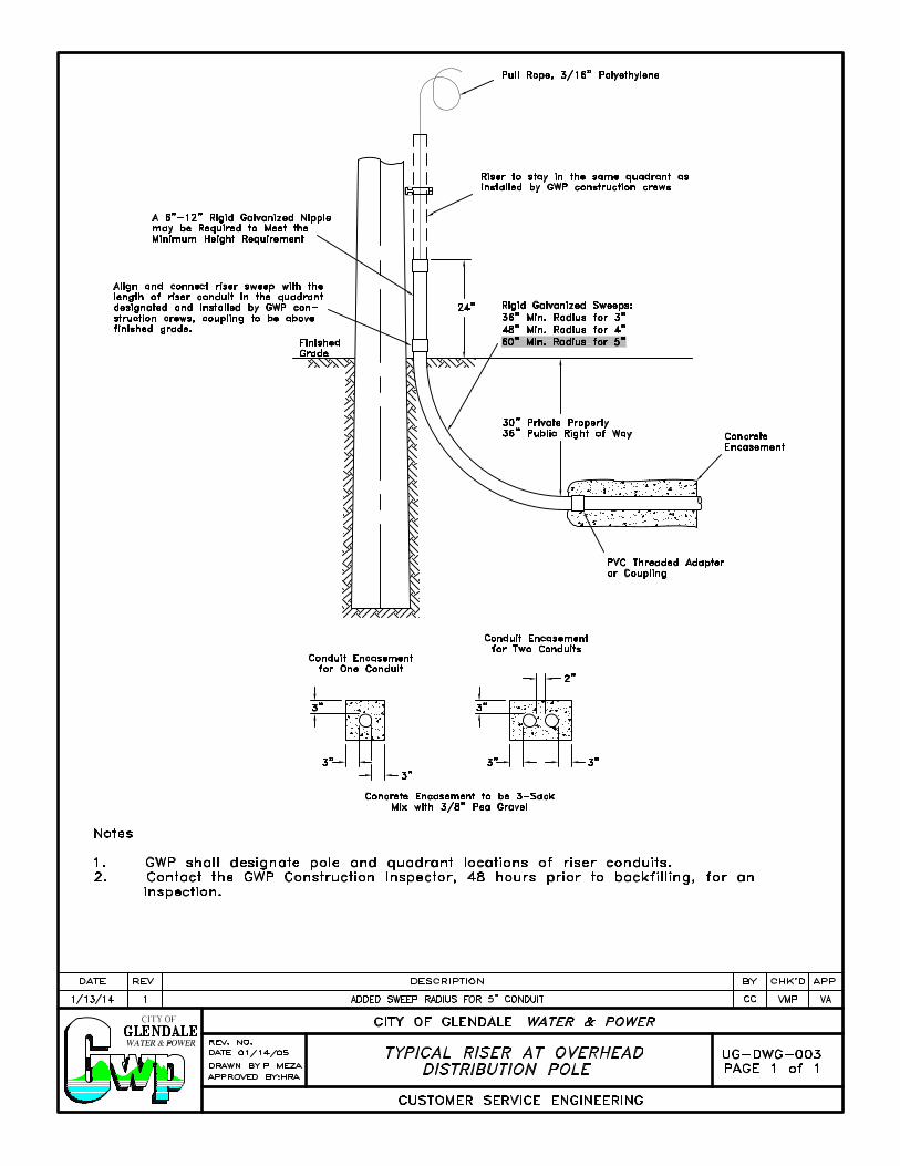
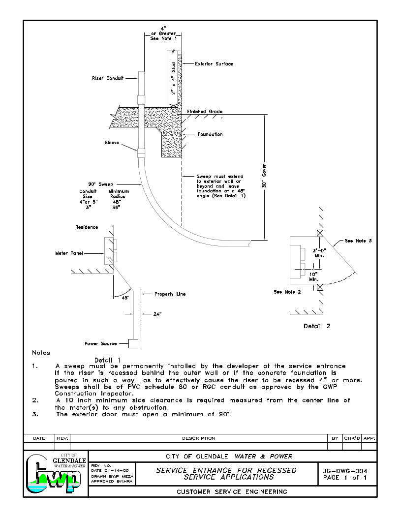
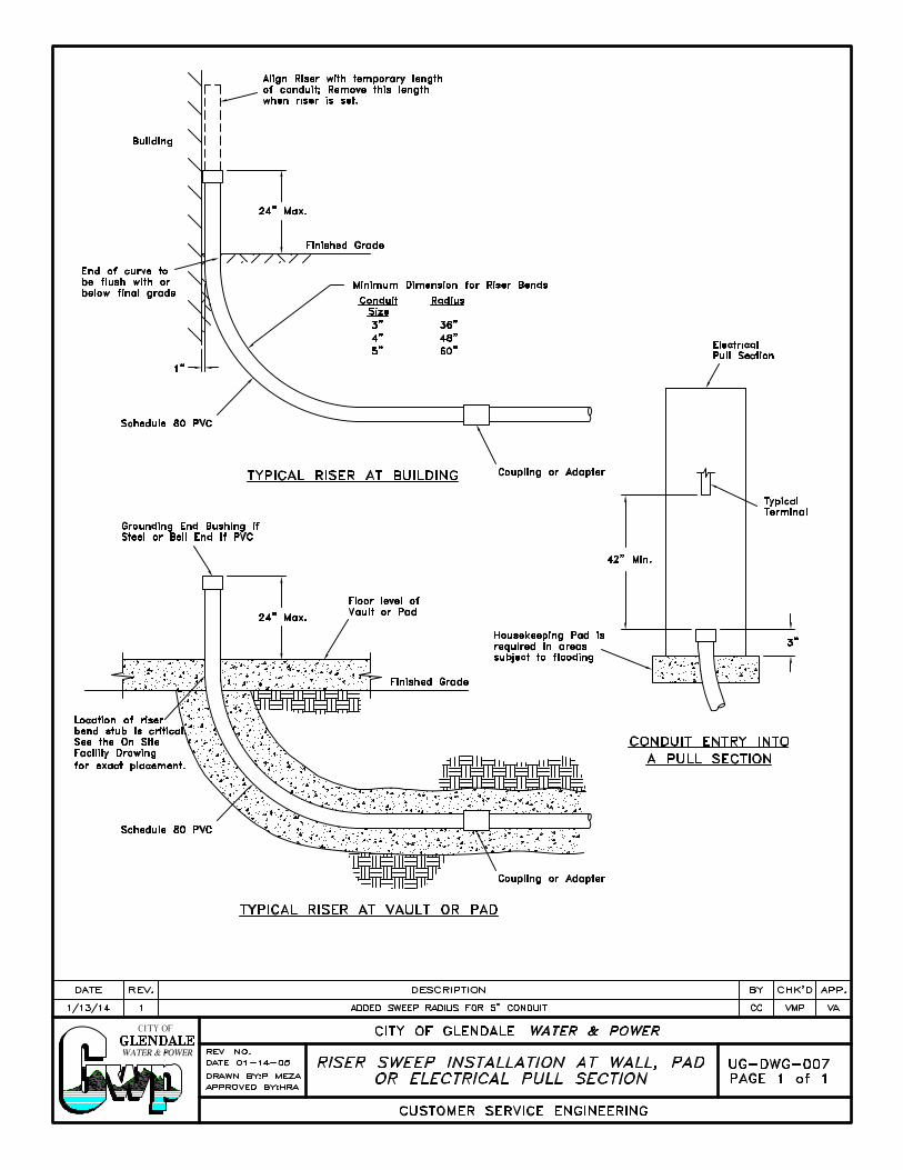
Secondary Conduit(s) Conduit(s) and sweep(s) shall be rigid galvanized or approved DB 100 plastic conduit and sweep per ANSI/ASTM F512 as last revised. Four inch conduit(s) shall have 48" and three inch conduits shall have 36" minimum radius rigid galvanized or schedule 80 plastic sweep at terminations. The riser sweeps on the pole shall be rigid galvanized, extended two feet above the finished grade. GWP shall designate the quadrant in which the riser conduit will be installed and the riser conduit will be installed by GWP construction crews. The contractor shall align and connect the riser sweep with the riser conduit installed by GWP. Minimum cover to be 30" in private property and 36" in public right-of-way. Conduits in public right-of-way shall be concrete encased as per UG-103, page 4 of 4, Conduit Encasement. Conduit encasement is not required if rigid galvanized conduit is used. Size and number of secondary conduits required will be specified in the service spot.
SERVICE CONDUIT(S) UG-103
Page 2 of 4
Secondary Distribution Conduit(s) in Private Property Secondary distribution conduits(s) in private property shall be concrete encased as per UG-103, page 4 of 4, Conduit Encasement. Conduit encasement is not required if rigid galvanized conduit is used.
Spare Secondary Conduit(s) All service spots will be designed with the minimum number of spare conduits required and the customer shall not obstruct any future entries into the distribution pull box or vault with concrete over pours.
Future Conduit(s) or Riser(s) All future conduits, if required, shall be supplied by GWP and installed by the customer. These future conduits are required so all customers can have access to the underground and overhead distribution system. If the installation of future service conduits is recommended, it is at the discretion of the owner of the project to install the conduits. These conduits will be clearly specified as recommended on service spot.
Primary Conduit(s) Conduit(s) and sweep(s) shall be rigid galvanized or concrete encased approved DB 100 plastic per ANSI/ASTM F512 as last revised. Four inch conduit(s) shall have 48" and three inch conduits shall have 36" minimum radius rigid galvanized or schedule 80 plastic sweep at terminations. The riser sweeps shall be rigid galvanized, extended two feet above the finished grade. GWP shall designate the quadrant in which the riser conduit to be installed and the riser conduit will be installed by GWP construction crews. The contractor shall align and connect the riser sweep with the riser conduit installed by GWP. Minimum cover to be 36". Size and number of primary conduits required to be specified in the service spot. Primary conduits shall be encased per UG-103, page 4 of 4, Conduit Encasement.
SERVICE CONDUIT(S) UG-103
Page 3 of 4
Spare Primary Conduit(s) A spare primary conduit or riser is only required for primary services 1200 amps, 480Y/277 or 2000 amps, 208Y/120 and larger. For services smaller than the above mentioned, a spare service conduit may be specified as recommended only.
Length of Secondary Service Run The maximum allowable length of duct between pull boxes is determined by the type and size of cables, the duct size, and the number of bends in the run. The following criteria must be taken into consideration for design of secondary runs:
a) Service conduits which run up to 150 feet in length are acceptable if they contain no more than two 90 degree sweeps in public right of way and two 90 degree sweeps in private property.
b) Service conduits which run up to 380 feet are acceptable with one 90 degree sweep in public right of way and two 90 degree sweeps in private property.
Route of Conduits
The entire route of the duct installed must be approved by GWP.
Pull Line and Mandrelling Contractor shall install Muletape minimum 1,250lb strength with footage markings or 3/16" diameter polyethylene pull line in all conduits. All conduits must be mandrelled while the GWP construction inspector is present. Contractor shall install pull line ahead of time before pulling mandrel in the presence of a GWP Construction Inspector. Customer must notify GWP by calling (818) 548-3920, 48 hrs in advance.
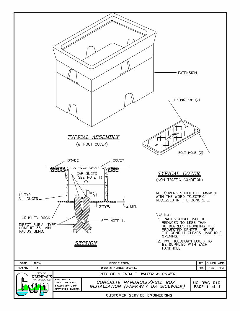
Conduit Termination All conduits terminating in vaults and walls of pull-boxes shall be terminated as follows: PVC conduits require end bells and steel conduits require grounding end bushings. All conduits entering a pull-box from the bottom shall extend no more than 4" above the gravel. Conduits stubbed into lots for future use shall be capped at their terminations.
SERVICE CONDUIT(S) UG-103
Page 4 of 4
Duct Bank Alignment The entire duct bank shall be laid in parallel to finished grade to minimize deflections in the duct line. Deviation from this requirement must be approved by GWP Construction Inspector.
Foreign Substructures Electrical ducts shall be separated from other substructures by a minimum clearance of 12" horizontally when paralleling and 6" vertically when crossing. Public Works Engineering Department shall be consulted for minimum clearances requirements from sewer lines and storm drains.
Curbs and Lot Corners Street curbs shall be in place and property lines staked prior to substructure installation. Grade stakes with an offset distance from substructure centerline may be substituted for curbs.
Conduit Encasement If required, conduits shall be encased in a 3.0 sack concrete mix containing 3/8” pea gravel. A 2" separation between conduits and a minimum concrete envelope of 3" around the perimeter shall be maintained.
Fiber Optic Conduit (Primary Services) Conduit(s) shall be a minimum of 4” inside diameter and shall be placed at the top of the conduit bundle. Installation requirements are the same as discussed in “Primary Conduit(s).” Smaller diameter conduit may be substituted with GWP’s prior approval.
TERMINATING ENCLOSURES UG-104
Page 1 of 3
Terminating Enclosures A terminating enclosure shall be provided for all underground services. Terminating lugs for the load side of landings shall be supplied by the customer. Terminating lugs for the line side will be provided by GWP. Every service terminating enclosure shall be in a permanently accessible location which is acceptable to GWP. Whenever a terminating enclosure is within a single occupancy building and such building is divided into multiple occupancy, all sets of service entrance conductors shall be brought to a single terminating enclosure located as required for multiple occupancy buildings. See MTR-105, “Meter Locations”. The following are acceptable terminating enclosures as permitted in these requirements.
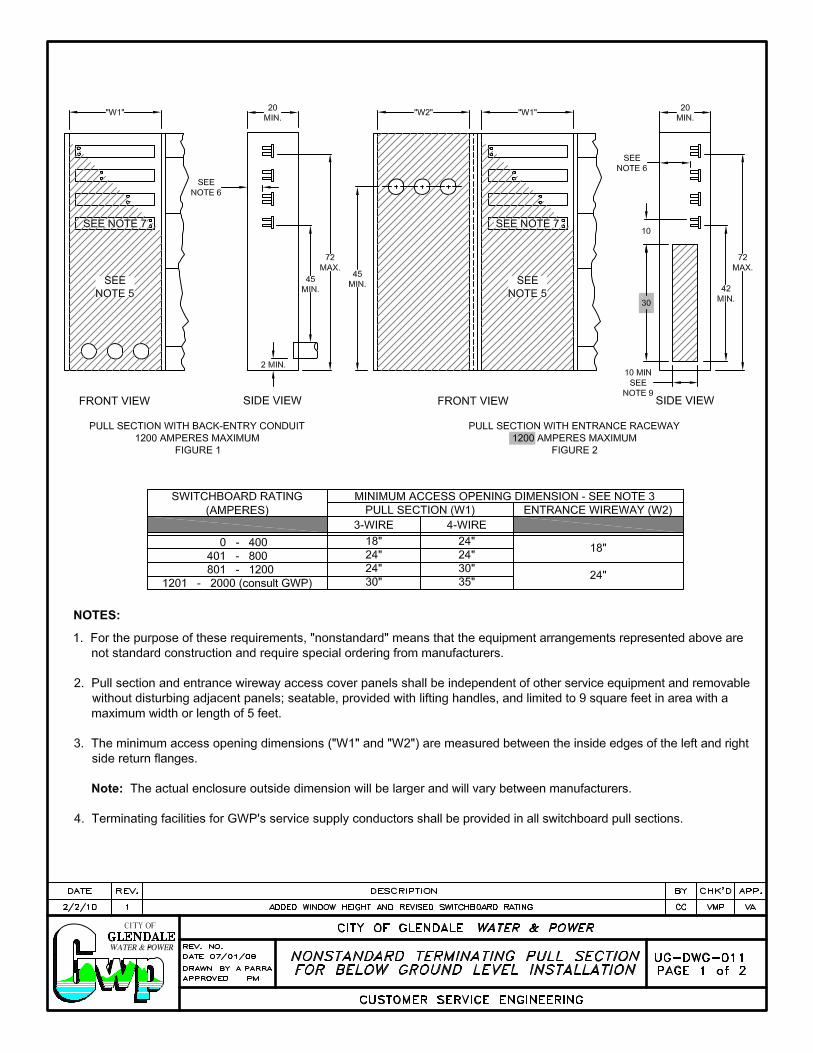
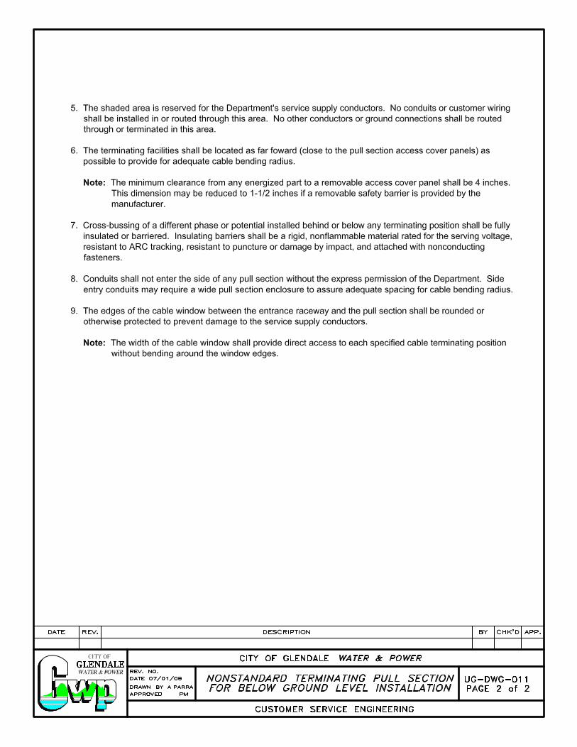
Wall Mounted Pull-boxes EUSERC DRAWING #315 EUSERC DRAWING #343 EUSERC DRAWING #344 Switchboard Pull Sections EUSERC DRAWING #345 EUSERC DRAWING #347 Safety Socket Boxes EUSERC DRAWING #304 EUSERC DRAWING #305 Meter post and pedestals EUSERC DRAWING #308 Combination meter panels with Terminating Sections EUSERC DRAWING #301 Combination Switchboard Service Section and Pull Section (with GWP Approval) EUSERC DRAWING #327 Nonstandard Terminating Pull UG-DWG-011 Sections for below ground level installations.
TERMINATING ENCLOSURES UG-104
Page 2 of 3
High Voltage Terminating Enclosures All services above 600 volts require special terminating enclosures. See PRI Section.
Subterranean Type Fuse Terminating Pull Box This type of service is not permitted.
Wall Mounted Type Terminating Pull Boxes and Switchboard Pull Sections (Located on an Exterior wall)
Wall mounted service terminating pull boxes may only be used per GWP discretion. These pull boxes and switchboard pull sections shall be located on or recessed in an exterior wall of the building served, facing outward. The enclosure shall be permanently accessible without entering the building, shall not project into any driveway, walk, or public way and shall have access and working space in compliance with UG-104, page 3 of 3 “Access to and Working Space in Front of Termination Enclosures” and MTR-110, page 3 of 4 “Working space Metering and Service Equipment”. The bottom of the wall mounted enclosures shall not be less than 6 inches above grade (working space).
Wall Mounted Type Terminating Pull Boxes and Switchboard Pull Sections (Located Inside a Building)
Terminating pull boxes and pull sections may be located inside a commercial or industrial building under the following conditions:
1. The service conduit shall be encased in not less than 2 inches of concrete or under a concrete floor at least 2 inches thick.
2. Wall mounted type pull boxes may only be used per GWP discretion. These pull
boxes and switchboard pull sections may be at grade floor level or may be installed in a basement having a ceiling height of not less than 7 feet. All such installations shall comply with access and working space requirements and subject to the approval of GWP.
TERMINATING ENCLOSURES UG-104
Page 3 of 3
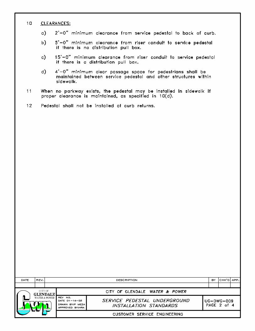
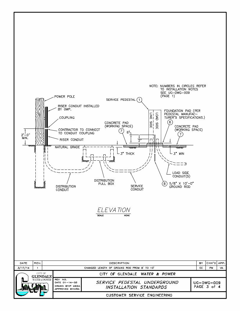
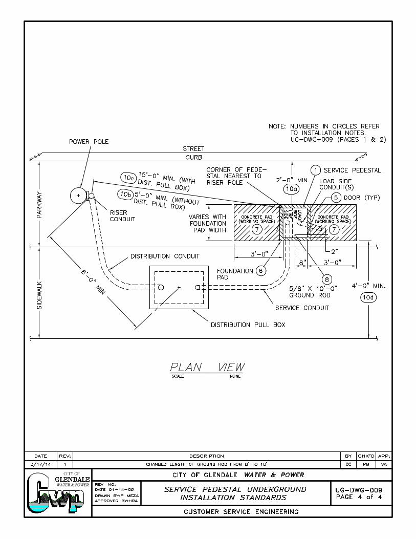
Access to and Working Space in Front of Termination Enclosures All terminating enclosures shall be provided 24 hour accessibility for installation and maintenance of GWP facilities. Access must be through walking space affording not less than 6'-6" height and 3 feet in width. A permanent, level standing and working surface shall be provided. It shall be clear and unobstructed, at least equal to the width and height of the terminating enclosure space. The work space shall extend in front of all terminating enclosures and their housings as required by NEC. The working space shall be located in private property and in no case shall be located or extended in the public right of way. In no case shall the height of the clear space be less than 6'-8". The width shall not be less than 3 feet. See UG-DWG-009 for clearances on non-residential service pedestals (0-200A).