ELECTRICAL SERVICE REQUIREMENTS ... - … · electrical service requirements electric utility...
115
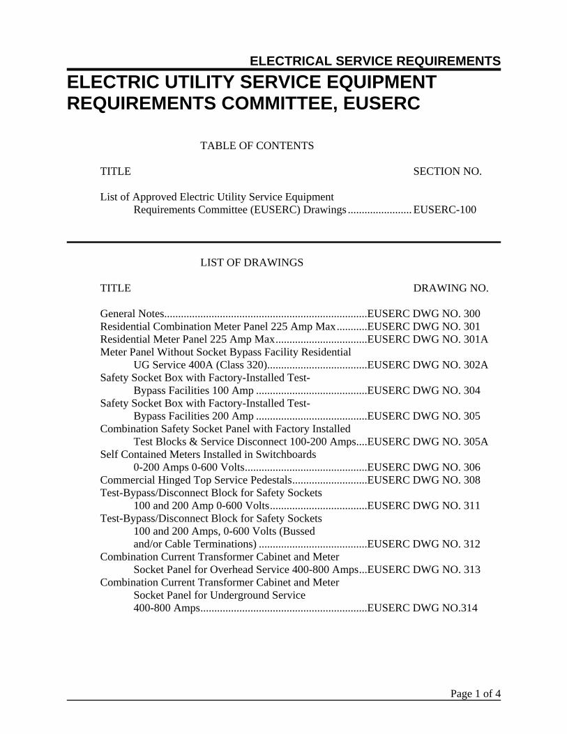
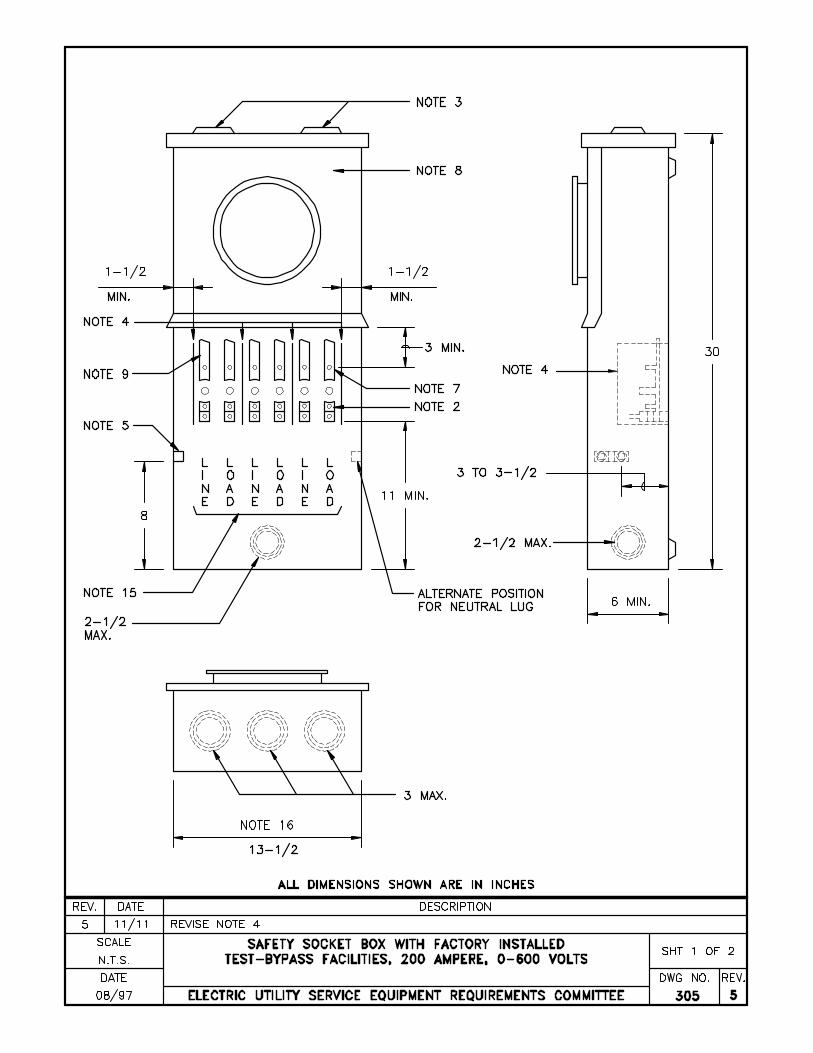
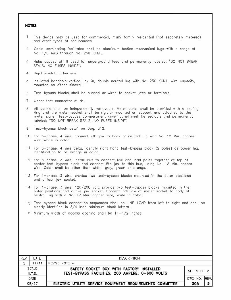
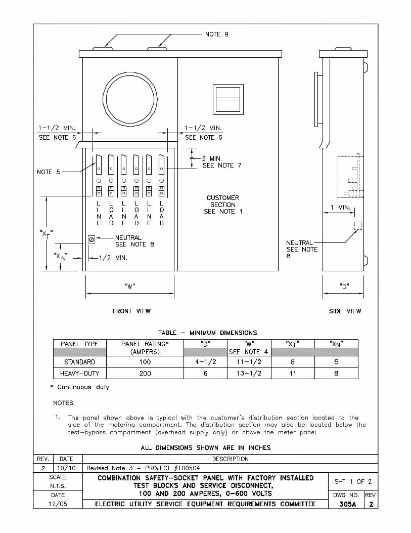
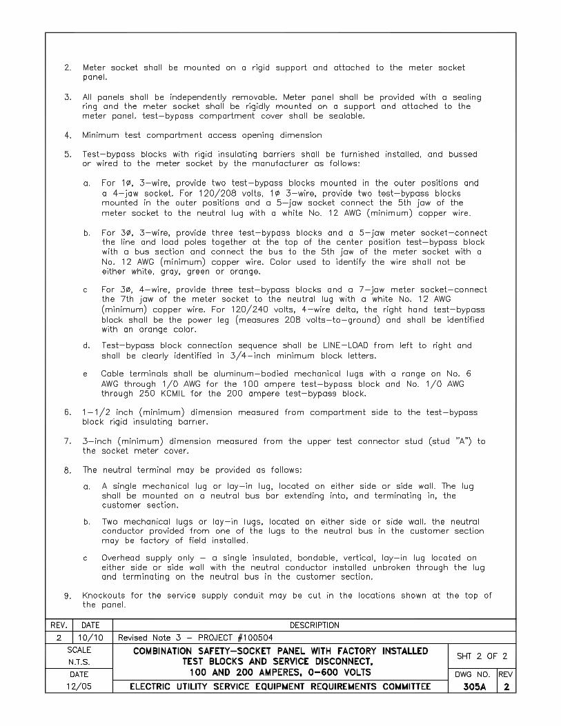
ELECTRICAL SERVICE REQUIREMENTS ELECTRIC UTILITY SERVICE EQUIPMENT REQUIREMENTS COMMITTEE, EUSERC Page 1 of 4 TABLE OF CONTENTS TITLE SECTION NO. List of Approved Electric Utility Service Equipment Requirements Committee (EUSERC) Drawings ....................... EUSERC-100 LIST OF DRAWINGS TITLE DRAWING NO. General Notes.........................................................................EUSERC DWG NO. 300 Residential Combination Meter Panel 225 Amp Max ...........EUSERC DWG NO. 301 Residential Meter Panel 225 Amp Max .................................EUSERC DWG NO. 301A Meter Panel Without Socket Bypass Facility Residential UG Service 400A (Class 320)....................................EUSERC DWG NO. 302A Safety Socket Box with Factory-Installed Test- Bypass Facilities 100 Amp ........................................EUSERC DWG NO. 304 Safety Socket Box with Factory-Installed Test- Bypass Facilities 200 Amp ........................................EUSERC DWG NO. 305 Combination Safety Socket Panel with Factory Installed Test Blocks & Service Disconnect 100-200 Amps....EUSERC DWG NO. 305A Self Contained Meters Installed in Switchboards 0-200 Amps 0-600 Volts............................................EUSERC DWG NO. 306 Commercial Hinged Top Service Pedestals...........................EUSERC DWG NO. 308 Test-Bypass/Disconnect Block for Safety Sockets 100 and 200 Amp 0-600 Volts ...................................EUSERC DWG NO. 311 Test-Bypass/Disconnect Block for Safety Sockets 100 and 200 Amps, 0-600 Volts (Bussed and/or Cable Terminations) .......................................EUSERC DWG NO. 312 Combination Current Transformer Cabinet and Meter Socket Panel for Overhead Service 400-800 Amps...EUSERC DWG NO. 313 Combination Current Transformer Cabinet and Meter Socket Panel for Underground Service 400-800 Amps............................................................EUSERC DWG NO.314
Transcript of ELECTRICAL SERVICE REQUIREMENTS ... - … · electrical service requirements electric utility...
ELECTRICAL SERVICE REQUIREMENTS ELECTRIC UTILITY SERVICE EQUIPMENT REQUIREMENTS COMMITTEE, EUSERC
Page 1 of 4
TABLE OF CONTENTS TITLE SECTION NO. List of Approved Electric Utility Service Equipment Requirements Committee (EUSERC) Drawings ....................... EUSERC-100 LIST OF DRAWINGS TITLE DRAWING NO. General Notes.........................................................................EUSERC DWG NO. 300 Residential Combination Meter Panel 225 Amp Max...........EUSERC DWG NO. 301 Residential Meter Panel 225 Amp Max.................................EUSERC DWG NO. 301A Meter Panel Without Socket Bypass Facility Residential UG Service 400A (Class 320)....................................EUSERC DWG NO. 302A Safety Socket Box with Factory-Installed Test- Bypass Facilities 100 Amp ........................................EUSERC DWG NO. 304 Safety Socket Box with Factory-Installed Test- Bypass Facilities 200 Amp ........................................EUSERC DWG NO. 305 Combination Safety Socket Panel with Factory Installed Test Blocks & Service Disconnect 100-200 Amps....EUSERC DWG NO. 305A Self Contained Meters Installed in Switchboards 0-200 Amps 0-600 Volts............................................EUSERC DWG NO. 306 Commercial Hinged Top Service Pedestals...........................EUSERC DWG NO. 308 Test-Bypass/Disconnect Block for Safety Sockets 100 and 200 Amp 0-600 Volts...................................EUSERC DWG NO. 311 Test-Bypass/Disconnect Block for Safety Sockets 100 and 200 Amps, 0-600 Volts (Bussed and/or Cable Terminations) .......................................EUSERC DWG NO. 312 Combination Current Transformer Cabinet and Meter Socket Panel for Overhead Service 400-800 Amps...EUSERC DWG NO. 313 Combination Current Transformer Cabinet and Meter Socket Panel for Underground Service 400-800 Amps............................................................EUSERC DWG NO.314
ELECTRICAL SERVICE REQUIREMENTS ELECTRIC UTILITY SERVICE EQUIPMENT REQUIREMENTS COMMITTEE, EUSERC
Page 2 of 4
LIST OF DRAWINGS (Continued)
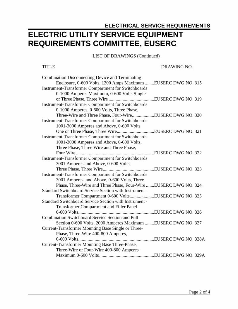
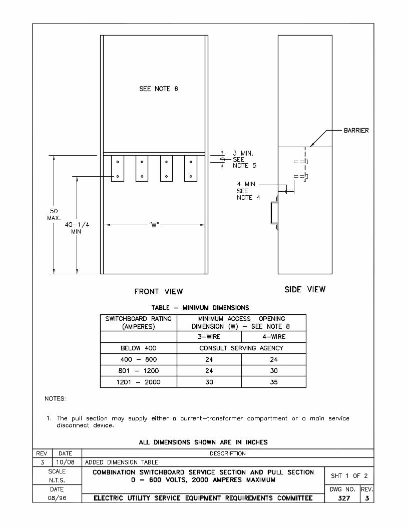
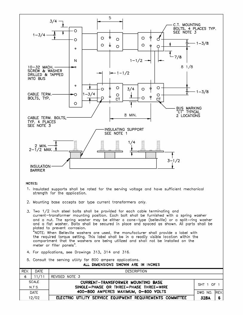
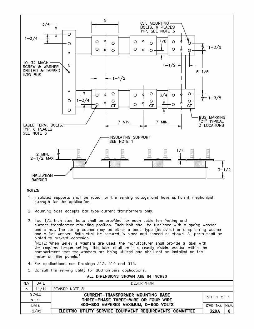
TITLE DRAWING NO. Combination Disconnecting Device and Terminating Enclosure, 0-600 Volts, 1200 Amps Maximum ........EUSERC DWG NO. 315 Instrument-Transformer Compartment for Switchboards 0-1000 Amperes Maximum, 0-600 Volts Single or Three Phase, Three Wire .......................................EUSERC DWG NO. 319 Instrument-Transformer Compartment for Switchboards 0-1000 Amperes, 0-600 Volts, Three Phase, Three-Wire and Three Phase, Four-Wire...................EUSERC DWG NO. 320 Instrument-Transformer Compartment for Switchboards 1001-3000 Amperes and Above, 0-600 Volts One or Three Phase, Three Wire................................EUSERC DWG NO. 321 Instrument-Transformer Compartment for Switchboards 1001-3000 Amperes and Above, 0-600 Volts, Three Phase, Three Wire and Three Phase, Four Wire ...................................................................EUSERC DWG NO. 322 Instrument-Transformer Compartment for Switchboards 3001 Amperes and Above, 0-600 Volts, Three Phase, Three Wire............................................EUSERC DWG NO. 323 Instrument-Transformer Compartment for Switchboards 3001 Amperes, and Above, 0-600 Volts, Three Phase, Three-Wire and Three Phase, Four-Wire .......EUSERC DWG NO. 324 Standard Switchboard Service Section with Instrument - Transformer Compartment 0-600 Volts.....................EUSERC DWG NO. 325 Standard Switchboard Service Section with Instrument - Transformer Compartment and Filler Panel 0-600 Volts.................................................................EUSERC DWG NO. 326 Combination Switchboard Service Section and Pull Section 0-600 Volts, 2000 Amperes Maximum ........EUSERC DWG NO. 327 Current-Transformer Mounting Base Single or Three- Phase, Three-Wire 400-800 Amperes, 0-600 Volts.................................................................EUSERC DWG NO. 328A Current-Transformer Mounting Base Three-Phase, Three-Wire or Four-Wire 400-800 Amperes Maximum 0-600 Volts...............................................EUSERC DWG NO. 329A

ELECTRICAL SERVICE REQUIREMENTS ELECTRIC UTILITY SERVICE EQUIPMENT REQUIREMENTS COMMITTEE, EUSERC
Page 3 of 4
LIST OF DRAWINGS (Continued)
TITLE DRAWING NO. Removable Link and Current-Transformer Support for Instrument-Transformer Compartments with 4-inch Bus 0-600 Volts ..............................................EUSERC DWG NO. 330 Removable Link and Current-Transformer Support for Instrument-Transformer Compartments with 5-inch Bus 0-600 Volts ..............................................EUSERC DWG NO. 331 15-Inch Hinged Meter Panel 0-600 Volts..............................EUSERC DWG NO. 332 Switchboard Panel for Socket Meters and Recorders............EUSERC DWG NO. 333 Safety Socket for Meters used with Instrument Transformers ..............................................................EUSERC DWG NO. 339 Combination Terminating Enclosure and Multi-meter Panels For Residential Services, 6 Meter Max, 600 Amp Max ............................................................EUSERC DWG NO. 342 Wall-mounted Pull Box with Terminating Facilities, 0-600 Volts, 1200 Amps Maximum ..........................EUSERC DWG NO. 343 Underground Pull Boxes........................................................EUSERC DWG NO. 344 Underground Service Termination Standard Switchboard Service Connection 400 to 4000 Amperes, 0-600 Volts.................................................................EUSERC DWG NO. 345 Underground Service Terminating Facilities in Pull Boxes or Pull Sections, 0-600 Volts .....................................EUSERC DWG NO. 347 Overhead Service Termination Standard Switchboard Service Section 0-600 Volts.......................................EUSERC DWG NO. 348 Busway Service Head, Single Lug Mounting........................EUSERC DWG NO. 349 Service Entrance from Underground Vault using Bus Bars ..EUSERC DWG NO. 351 Clearances for Residential Multiple Metering Installations ................................................................EUSERC DWG NO. 353 Outdoor or Raintight Enclosures for Switchboards 0-600 Volts.................................................................EUSERC DWG NO. 354 General Notes.........................................................................EUSERC DWG NO. 400 High Voltage Metering Enclosure 2400 – 15000 Volt Service........................................................................EUSERC DWG NO. 401 High Voltage Metering Enclosure 15001 – 27000 Volt Service........................................................................EUSERC DWG NO. 404
ELECTRICAL SERVICE REQUIREMENTS ELECTRIC UTILITY SERVICE EQUIPMENT REQUIREMENTS COMMITTEE, EUSERC
Page 4 of 4
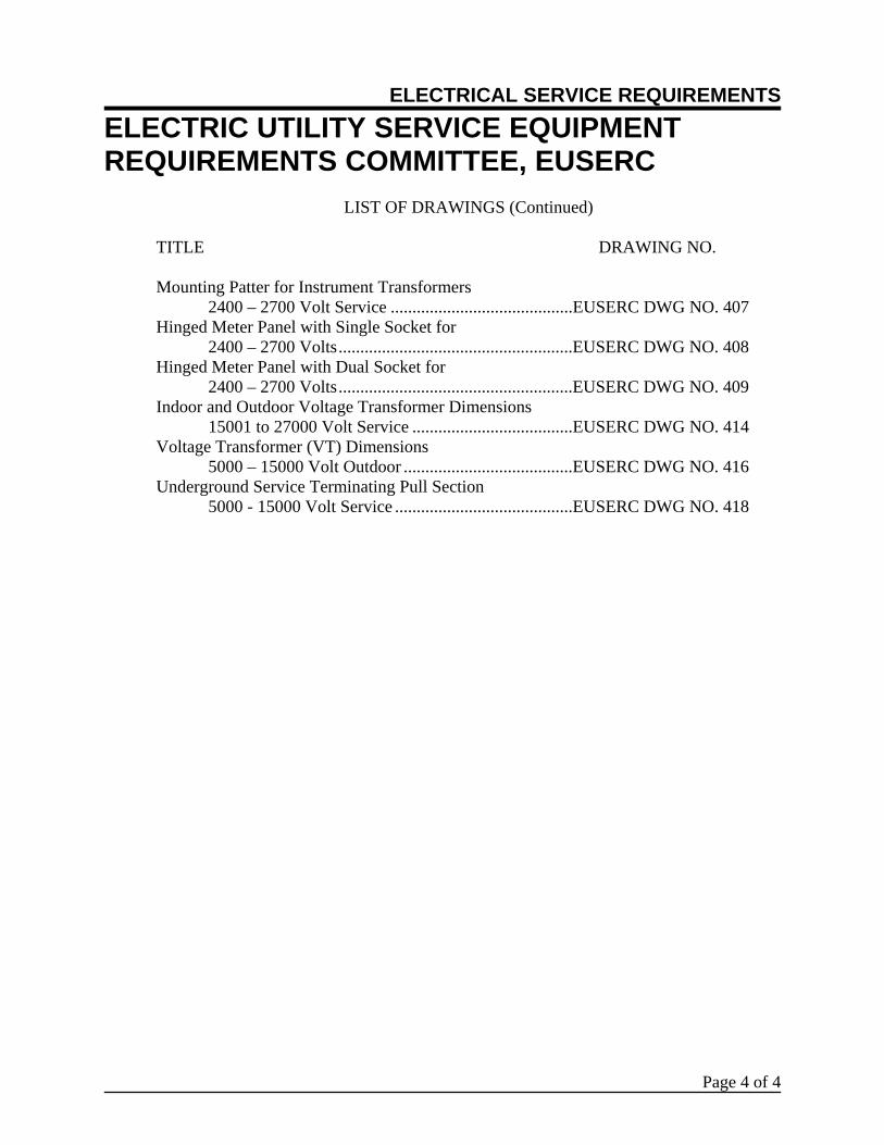
LIST OF DRAWINGS (Continued)
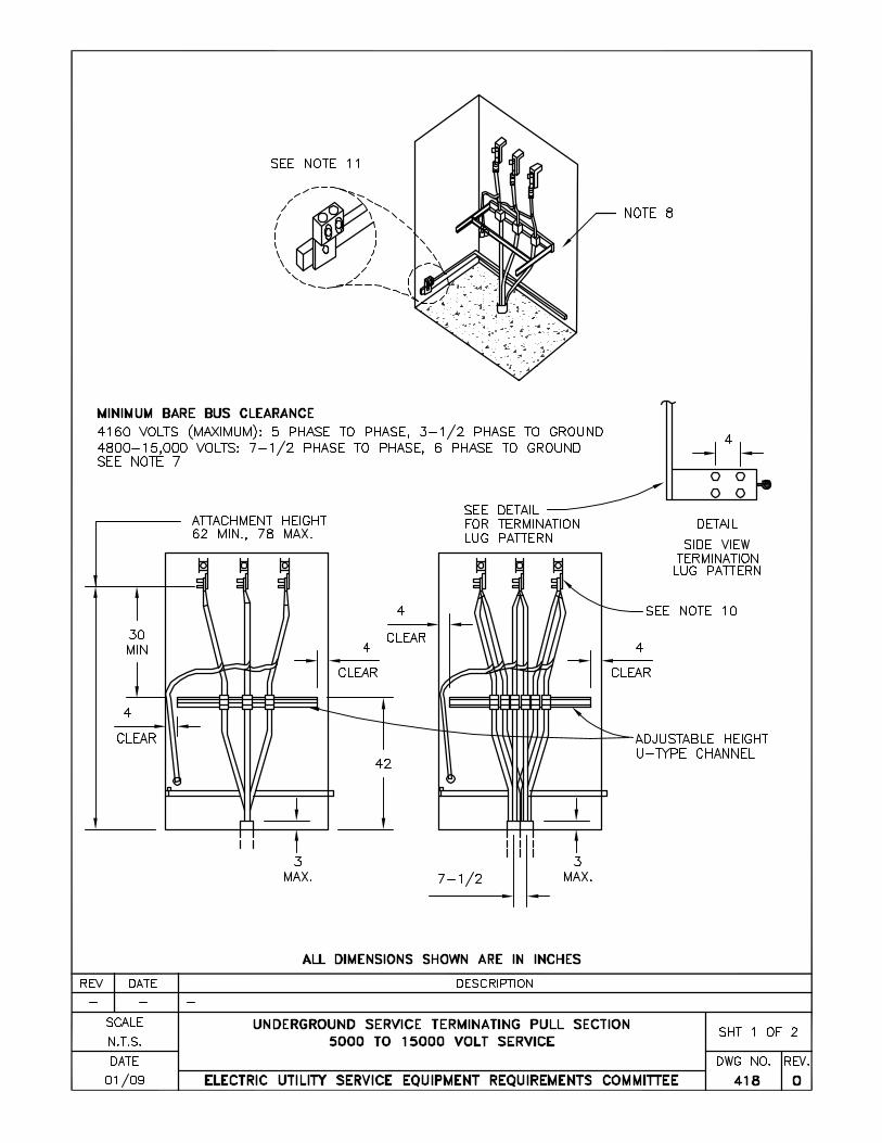
TITLE DRAWING NO. Mounting Patter for Instrument Transformers 2400 – 2700 Volt Service ..........................................EUSERC DWG NO. 407 Hinged Meter Panel with Single Socket for 2400 – 2700 Volts......................................................EUSERC DWG NO. 408 Hinged Meter Panel with Dual Socket for 2400 – 2700 Volts......................................................EUSERC DWG NO. 409 Indoor and Outdoor Voltage Transformer Dimensions 15001 to 27000 Volt Service .....................................EUSERC DWG NO. 414 Voltage Transformer (VT) Dimensions 5000 – 15000 Volt Outdoor .......................................EUSERC DWG NO. 416 Underground Service Terminating Pull Section 5000 - 15000 Volt Service .........................................EUSERC DWG NO. 418
SERVICE REQUIREMENTS COMMITTEE
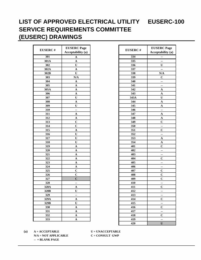
EUSERC # EUSERC Page Acceptability (a) EUSERC # EUSERC Page
Acceptability (a)301 A 334 --
301A A 335 --302 U 336 U
302A A 337 --302B U 338 N/A303 N/A 339 C304 A 340 --305 A 341 --
305A A 342 A306 A 343 A307 U 343A U308 A 344 A309 U 345 A310 -- 346 --311 A 347 A312 A 348 A313 C 349 C314 C 350 --315 A 351 C316 U 352 --317 U 353 A318 U 354 A319 A 401 C320 A 402 --321 A 403 --322 A 404 C323 A 405 --324 A 406 --325 C 407 C326 C 408 C327 C 409 C328 -- 410 --
328A A 411 C328B U 412 --329 -- 413 --
329A A 414 C329B U 415 --330 A 416 C331 A 417 --332 A 418 C333 A 419 --
420 U
(a) A = ACCEPTABLE U = UNACCEPTABLEN/A = NOT APPLICABLE C = CONSULT GWP-- = BLANK PAGE
LIST OF APPROVED ELECTRICAL UTILITY EUSERC-100
(EUSERC) DRAWINGS
EUSERC Drawing 300
Sheet 1
METERING AND SERVICE EQUIPMENT (0-600V) I. SCOPE
A. This section contains minimum manufacturing requirements for utility metering and service equipment rated 0-600V.
B. The following general notes apply to all drawings in this section where applicable. Each
drawing may also contain additional notes which should be considered unique to that drawing unless reference is made to another specific drawing or section.
C. Refer to Section 200 for specific utility requirements and utility acceptability of these
requirements. D. Refer to installation guide section for typical application and installation requirements.
II. METERING EQUIPMENT REQUIREMENTS, GENERAL
These Requirements are based on practices that are necessary in order to supply uniform satisfactory and safe service. Interpretations or clarifications of intent of these Requirements are subject to EUSERC approval. Installations shall also conform to the provisions of applicable codes and ordinances of local inspection authorities and the servicing agency. A. Grounding, General
1. Lugs for terminating the customer’s ground wire (or other grounding conductors) shall be
located outside of the sealable section and shall be designed to readily permit the customer's neutral system to be isolated, when necessary, from the serving agency.
2. Ground bus, when provided, shall be located at the rear of underground terminating
enclosures (i.e. pull boxes and pull sections).
B. Meter Sequence The metering arrangement approved as standard and required by all the serving agencies provides for the line current to enter first the meter and then the disconnecting means and overload protective devices, (meter-switch-fuse sequence). For multiple meter installations, refer to local codes.
C. Meter Access Customer locking means for meter enclosures shall provide for independent access by the serving agency.
D. Meter Heights Meters shall be located not more than 75 inches and not less than 48 inches above the ground or standing surface when installed outdoors. When meters are enclosed in a cabinet or indoors in a meter room, the minimum height may be reduced to 36 inches. The meter height shall be measured to the meter axis. Exception: Utilities in snow areas may require increased height.
EUSERC Drawing 300
Sheet 2
E. Meter Sockets, General 1. See Section 200 for tabulation of meter socket requirements of member utilities. 2. The socket and enclosure shall be designed in accordance with the latest revision of AEIC-
EEI-NEMA Standards for Watthour Meter Sockets, Publication ANSI C12.7, and Underwriters Laboratories Standard for Meter Sockets UL414. Socket rim to jaw clearance shall be no less than ANSI C12.7 (0.500”) or more than (0.690”).
Exception: The 0.690” dimension does not apply to transformer rated sockets and ground and neutral clips on self-contained sockets.
3. Meter sockets provided for self-contained meters shall be rated as follows:
a. For residential service applications, meter sockets shall have a maximum ampacity
rating not less than the ampacity rating of the associated service disconnect. The maximum ampacity rating is 125% of the continuous-duty rating.
b. For commercial and industrial service applications, meter sockets shall have a
continuous-duty rating of 100 amperes for service disconnects rated up to 125 amperes (maximum) and a continuous-duty rating of 200 amperes for service disconnects rated up to 250 amperes (maximum).
4. Sockets for self-contained meters shall be furnished, installed and wired by the customer.
Diagrams of connections are shown on Drawing G1 of the installation guides. 5. When self-contained meter sockets are installed in switchboards, they are to be wired by the
switchboard manufacturer. Consult Utility for use of lever bypass meter sockets. 6. Sockets for instrument transformer installations shall be furnished and installed by the
customer. The serving agency will furnish and install the normal secondary wiring from the instrument transformers to the meter socket.
7. Potential taps, including the neutral potential tap, shall be located behind a sealed panel.
The customer's grounding electrode connection shall not be located within the meter socket or socket area of a combination CT / meter enclosure.
8. Ring-type sockets shall be furnished with sealing rings. Consult Utility for use of ringless
sockets. 9. Instrument-rated meter sockets installed on:
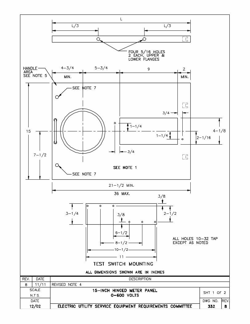
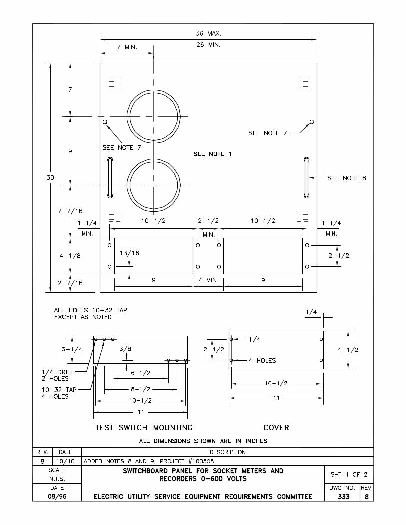
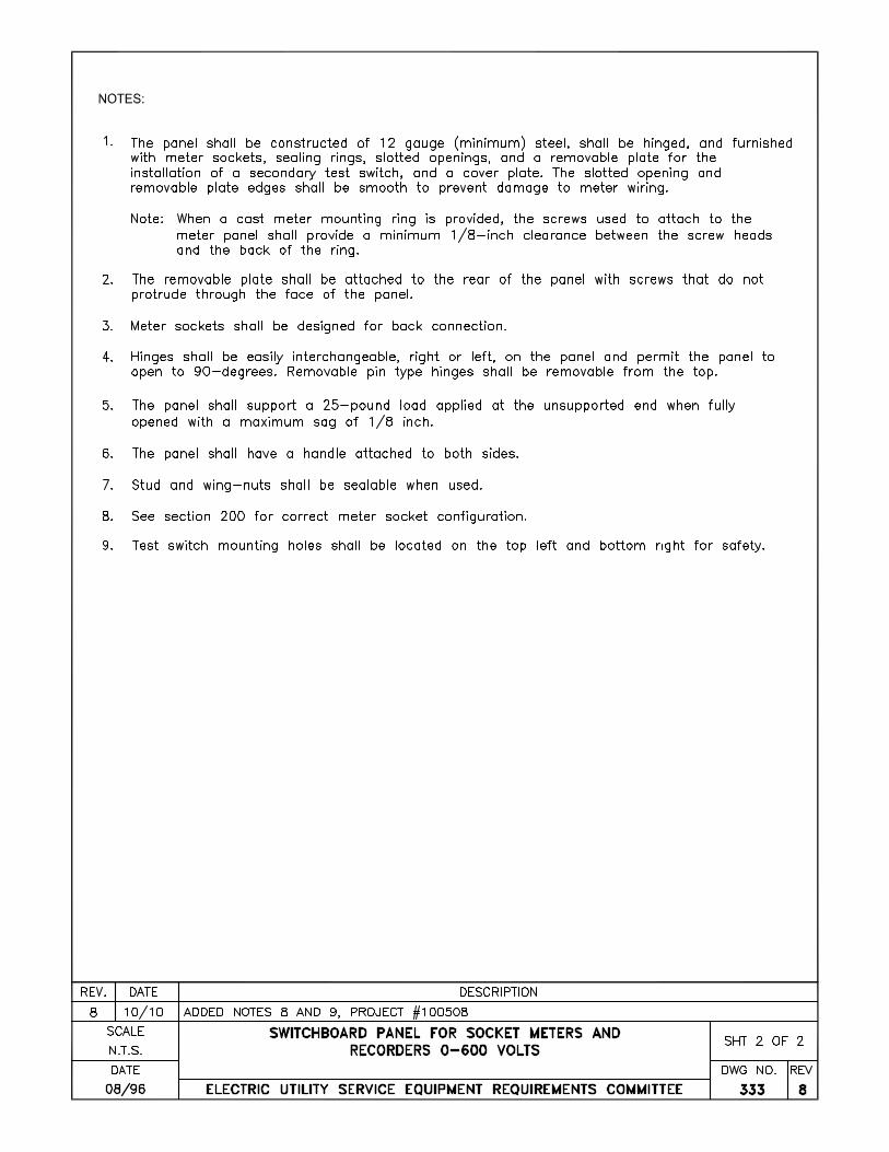
a. Hinged panels shall be fabricated and installed by the manufacturer for back connection. See Dwg. 332 and 333
Note: Screws used to mount cast meter sockets to hinged panels shall provide a 1/8” minimum clearance between the screw head and the back of the meter socket ring.
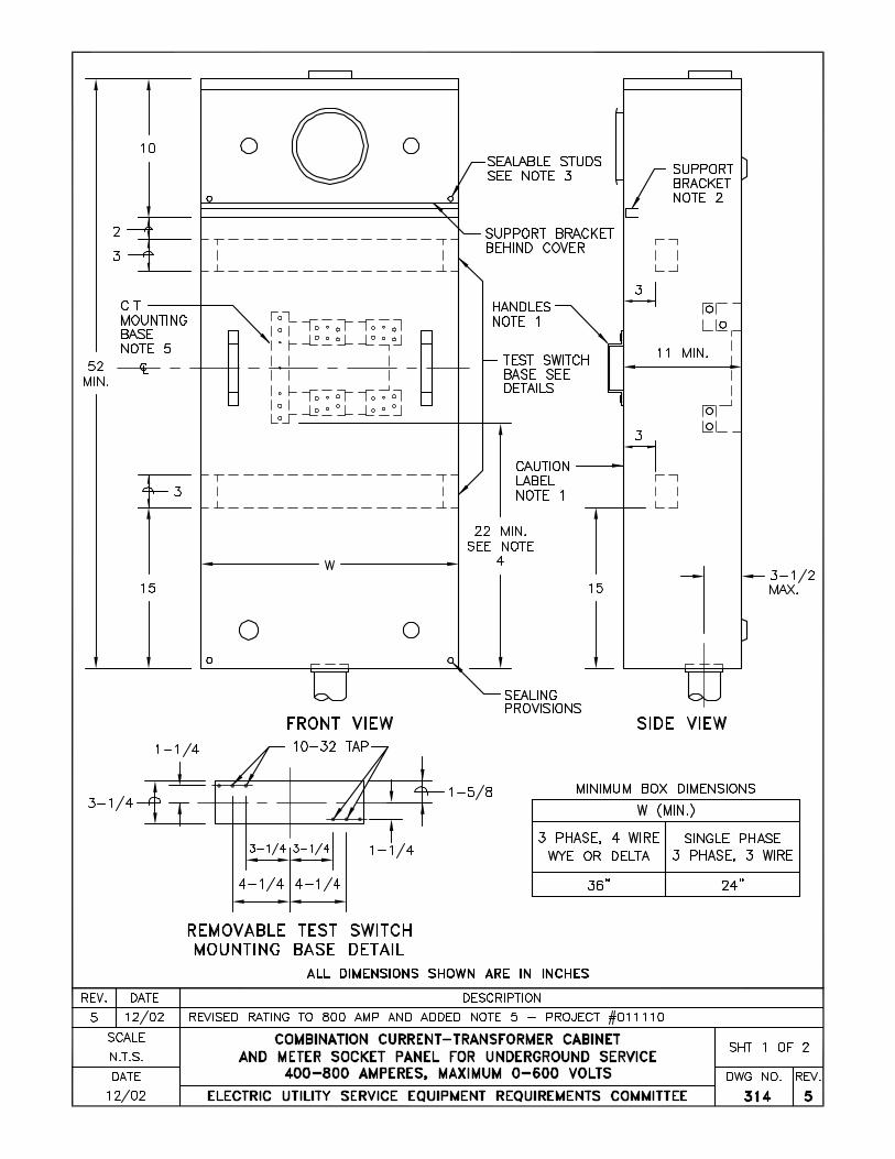
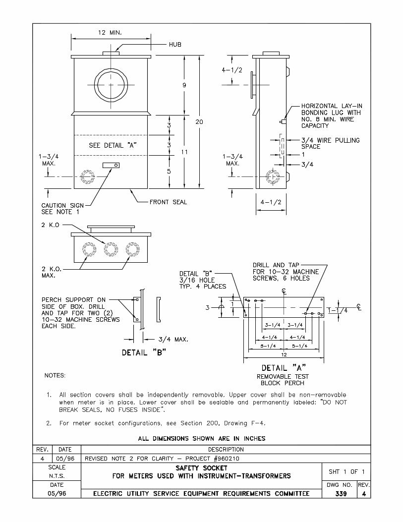
b. Non-hinged panels shall be fabricated and installed by the manufacturer for front
connection. See Drawing 313, 314 and 339.
Note: Meter sockets shall be attached with machine screws so that they may be interchanged or replaced. Sheet metal, self-tapping screws are not acceptable.

EUSERC Drawing 300
Sheet 3
10. All self-contained meter sockets shall be rigidly attached to the backwall of the socket enclosure or to a stationary support connected to the enclosure. For ring-type meter panels, the meter sockets shall be attached to the meter panel to assure alignment of the socket ring to the socket jaws and prevent removal of the panel with the meter in place. Sheet metal or self-tapping screws are not acceptable.
F. Meter Sockets with Test-Bypass, Disconnect Facilities
1. Sockets equipped with test-bypass disconnect facilities are required for some installations
and prohibited on others. For use in any particular locality, consult the serving agency. G. Meter & Cover Panels, General
1. The hinged meter panels shown on Drawings 332 & 333 are designed to accommodate only
transformer-rated socket meters. Self-contained sockets shall not be mounted on hinged panels.
2. The nonhinged meter panels shall not be used in front of a current transformer section. For
a specially engineered switchboard, the nonhinged panel as shown on Drawing 336 will accommodate a socket-type meter when used with current transformers
3. Not more than two meters shall be mounted on any removable meter panel. 4. Additional space may be required for recording or graphic demand meters (see Drawing
333). 5. Hinged meter panels and filler panels shall be equipped with stops to prevent inward
swinging beyond the front surface of the switchboards. 6. A hinged instrument transformer cabinet cover may be used provided there is proper
clearance to open the cover when the cabinet is installed. A cabinet with a hinged cover shall be designed so that the cover cannot be removed by tampering with the hinges when the cabinet cover is closed. Provisions shall be made for sealing the cabinet cover by use of approved method.
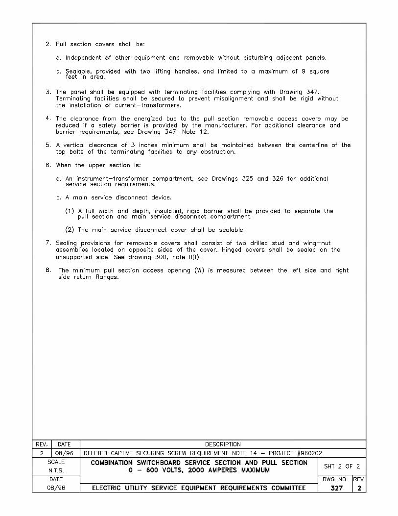
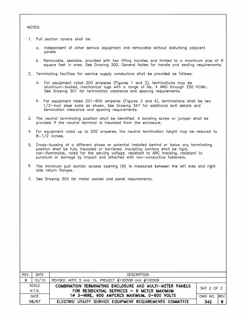
7. All pull and termination section cover panels shall be removable, sealable, provided with
two lifting handles and limited to a maximum size of nine square feet in area.
H. Lifting Handles 1. When lifting handles are required on panels and covers, each handle shall be sized for full
hand grasping, securely attached and have strength to withstand handling stresses of a minimum of 75 pounds.
Note: Chest type handles with a folding bale grasp are not acceptable.
I. Sealing
1. All cover panels, removable access panels and hinged panels for compartments containing unmetered conductors shall be sealable. When a raceway or conduit for meter secondary wiring is necessary, such a raceway or conduit shall be sealable. No removable panel or cover requiring sealing shall be located behind other panels, covers or doors (except raintight enclosure doors).
EUSERC Drawing 300
Sheet 4
Note: Carriage bolts may be used to secure cover panels in place of sealing provisions when the bolts are installed at the factory and do not require field removal and installation to complete assembly of the switchboard sections.
2. Sealable latches, stud and wing-nuts, or sealing screws shall be provided as the means of
sealing removable or hinged access covers. 3. Hinged cover panels shall be sealed on the side opposite the hinges. 4. Removable cover panels shall be sealed with stud and wing-nut assemblies on opposite
sides of the cover. Alternate sealing methods may be used if the removable covers are self-supporting with the captive screws and sealing provisions removed.
5. Sealing and securing devices shall be provided as follows:
a. Stud and wing-nut assemblies shall consist of a 1/4-inch x 20 (minimum) stud and an associated wing-nut, each drilled 0.0635 inches (minimum) for sealing purposes. The stud shall be securely attached so as to not loosen or screw out when being fastened.
b. Sealing screws shall be drilled 0.0635 inches (minimum) for sealing purposes.
c. Latching devices shall be designed to permit positive locking and be made of a durable
corrosion resistant material.
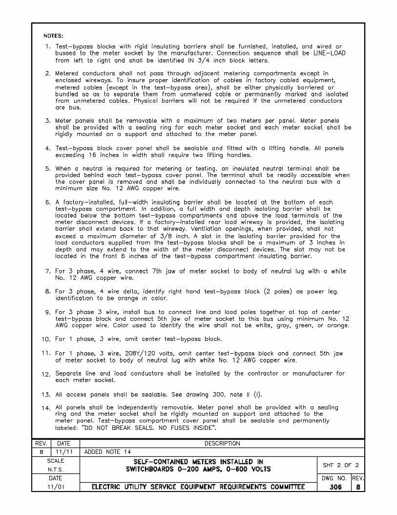
J. Cover Panel Labeling Test-bypass block compartment cover panels shall have a caution sign on the front reading "Do Not Break Seal -- No Fuses Inside."
K. Unmetered Conductors Customer unmetered service wires and metered load wires are not to be run in the same conduit, raceway or wiring gutter. Metered and unmetered wires shall be separated by suitable barriers. Metered wires from the customer's distribution section (branch circuits) shall not pass through sealable sections. For exceptions, see Apartment Metering.
L. Bus Bars 1. Ampacity
a. The dimensions in these requirements are based on the use of rectangular bus bar. Ampacities of bus bar conductors shall be based on UL-891. Standard for Dead-Front Switchboard, including ampacities based on thermal limits provided for therein. Maximum widths and number of bus bars shall conform to EUSERC requirements.
b. Ampacity of instrument transformer compartments bus shall conform to NEMA
Standards Publication PB2, Part 6.04, Paragraph A, for Section Bus.
2. Plating Aluminum bus bars shall be plated to prevent corrosion.
3. Attachment to the Enclosure
EUSERC Drawing 300
Sheet 5
Bus bars and other hardware attached to the outer walls of the enclosure shall be secured with devices that may not be loosened from the outside. Screws or bolts requiring special tools for installation or removal are not acceptable.
M. Service Disconnects
1. Meter Disconnects, General a. For each and every meter, the customer shall furnish and install a circuit breaker, fused
switch, or other approved disconnecting means with over-current protection referred to in these requirements as a meter disconnect.
b. The meter disconnect shall control all of and only, the energy registered by its related
meter. c. Where permitted by the serving agency, the meter disconnect may consist of up to six
separate devices.
2. Meter Disconnects, Locking Provisions
a. Meter disconnects supplied from instrument-transformer compartments shall be capable of being locked in the open (off) position.
b. Locking provisions may be:
(1) A lockout device which is incorporated as an integral part of each meter
disconnect, or (2) A lockable cover for each meter disconnect where the lock prevents the operation
of the disconnect and prevents removal of the cover, or (3) A lockable cover for multiple meter disconnects where the lock prevents the
operation of any of the disconnects, prevents removal of the cover and all disconnects are supplied from a single instrument transformer compartment.
(4) Items 1, 2, and 3 shall be permitted to be accomplished by a maximum of two (2)
locking provisions per disconnect. (5) For fused disconnects, the fuse access cover shall be lockable when the disconnect
is in the off (open) position. (6) All locking provisions for disconnects rated less than 400 amperes shall accept a
lock shank of not less than 1/4 inch. (7) All locking provisions for disconnects rated 400 amperes and above shall accept a
lock shank of not less than 5/16 inch.
EUSERC Drawing 300
Sheet 6
3. Main Service Disconnects a. A main service disconnect device is installed on the supply (line) side of a group of
meter sockets and may be a circuit breaker, fused disconnect, or other approved disconnecting means.
b. A service disconnect shall be installed on the supply (line) side of more than six meter
sockets. c. A service disconnect may be permitted on the supply side of two to six meter sockets.
Consult the serving agency for specific requirements. d. A service disconnect is not permitted on the supply (line) side of a single meter socket
(Old Sequence). e. The cover on a line side disconnect shall be sealable, (see Dwg 315 Note 5).
N. UTILITY COMPARTMENT LABELING
Manufacturers shall provide information and safety labels in utility compartments as follows:
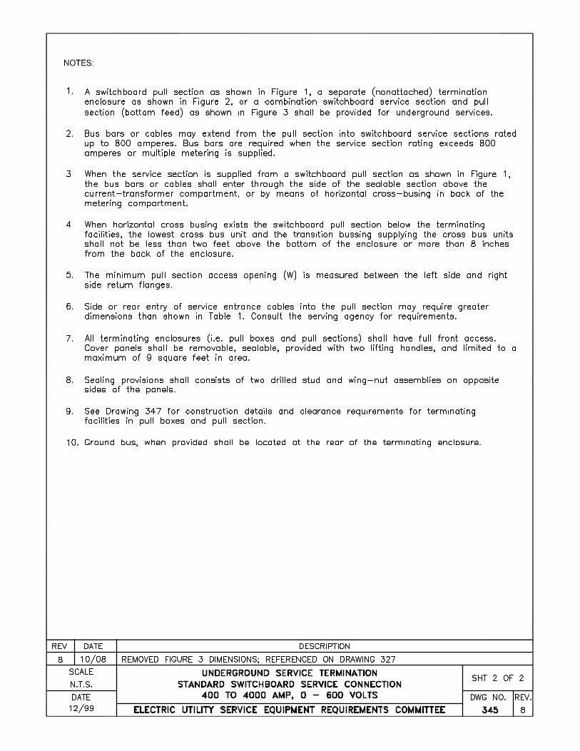
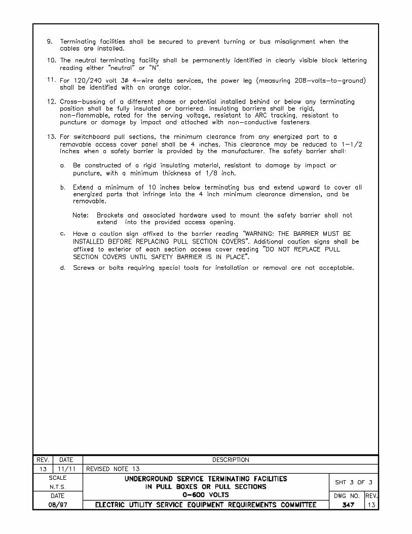
1. Caution labels for switchboard pull sections shall be provided on the safety barrier and cover of each pull section where energized bus is less than 4 inches from removable access cover panels. See drawing 347 for additional requirements.
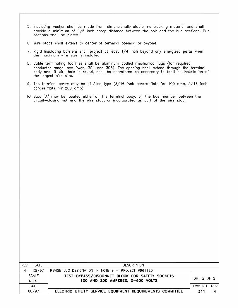
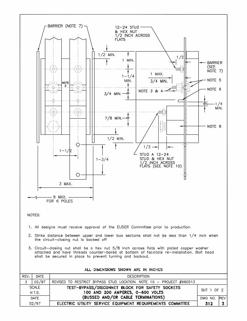
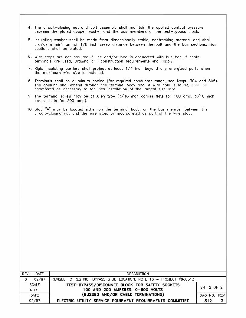
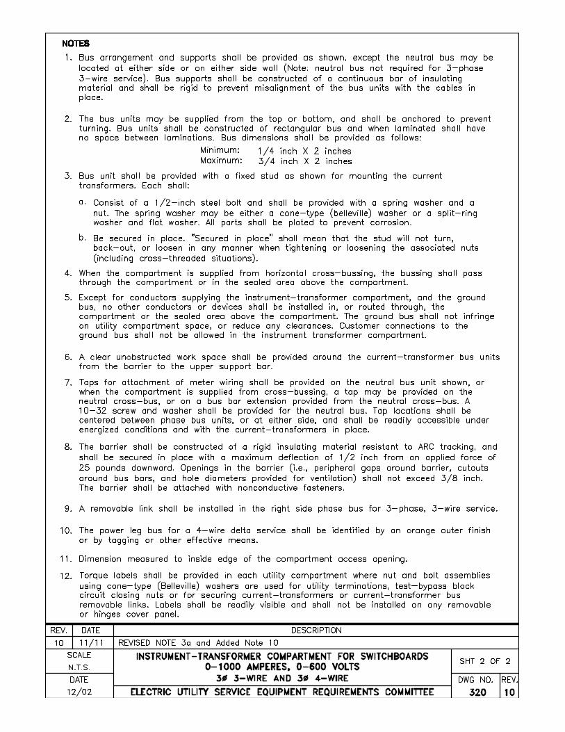
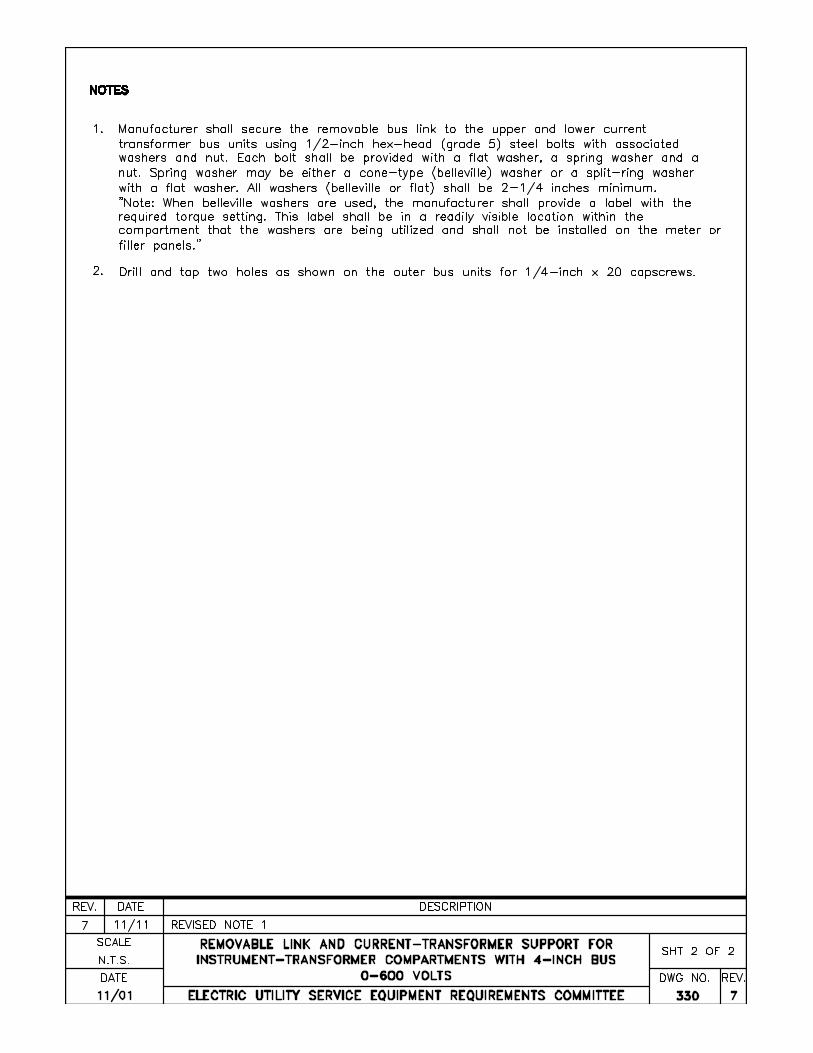
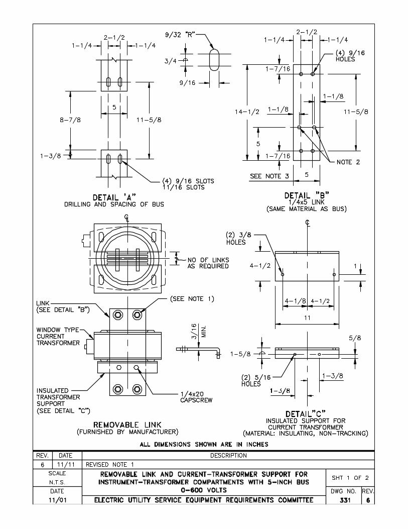
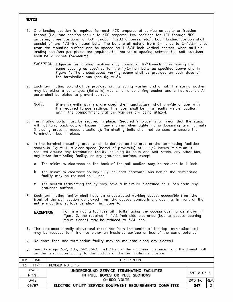
2. Torque labels shall be provided in each utility compartment where nut and bolt assemblies using cone-type (Belleville) washers are used for utility terminations, test-bypass block circuit closing nuts, or for securing current transformers or current transformer bus removable links. Labels shall be readily visible and shall not be installed on any removable or hinged cover panel.
a. For termination labeling see drawing 347.
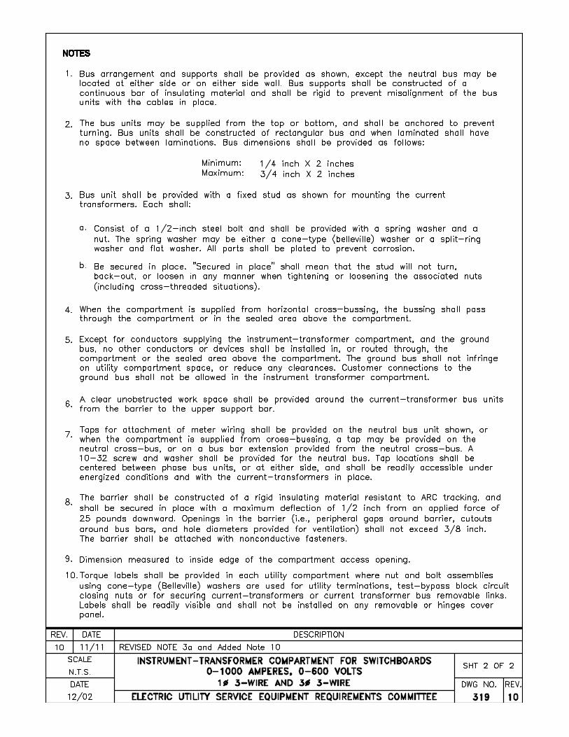
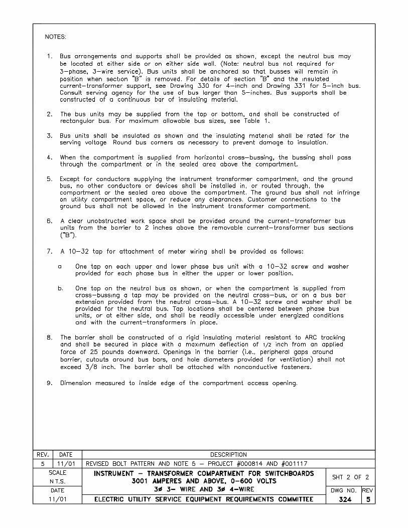
b. For current transformer installation labeling, see drawings 319, 320, 328A, 328B, 329A, 329B, 330, and 331.
III. SELF-CONTAINED RATED METERING INSTALLATION
Self-contained meters are designed to carry rated current and be energized at line potential. They do not require auxiliary instrument transformers to step down line current or voltage. A. Residential, General
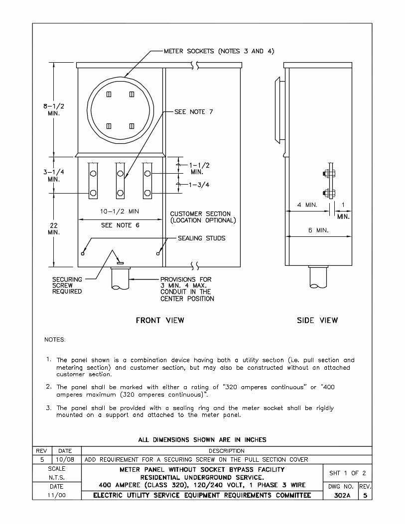
Four types of self-contained meters are commonly used for this application. 1. Class 100 socket-type meter 2. Class 200 socket-type meter 3. Class 320 socket-type meter 4. Class 400 bolt-in type meter (See Section 200 for specific utility requirements) Note: Automatic socket bypass devices are not allowed.
EUSERC Drawing 300
Sheet 7
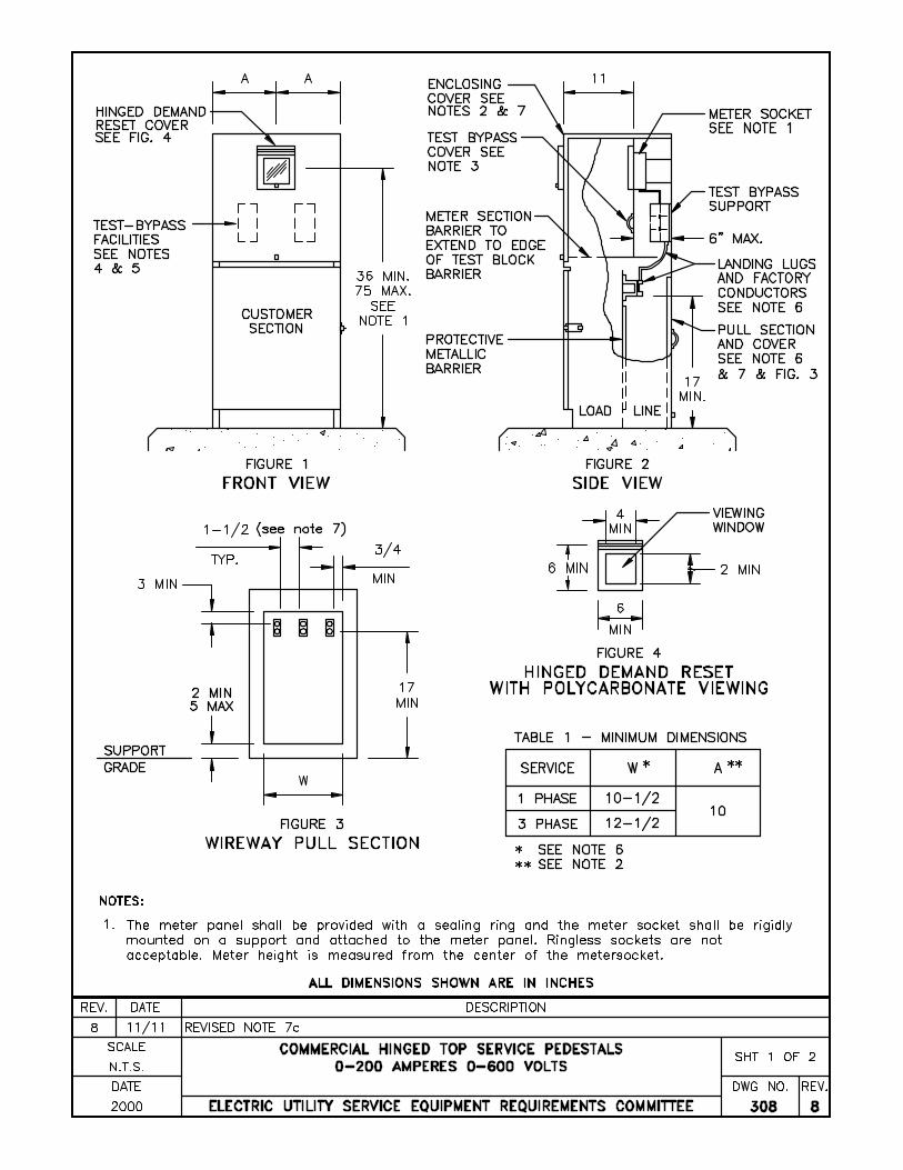
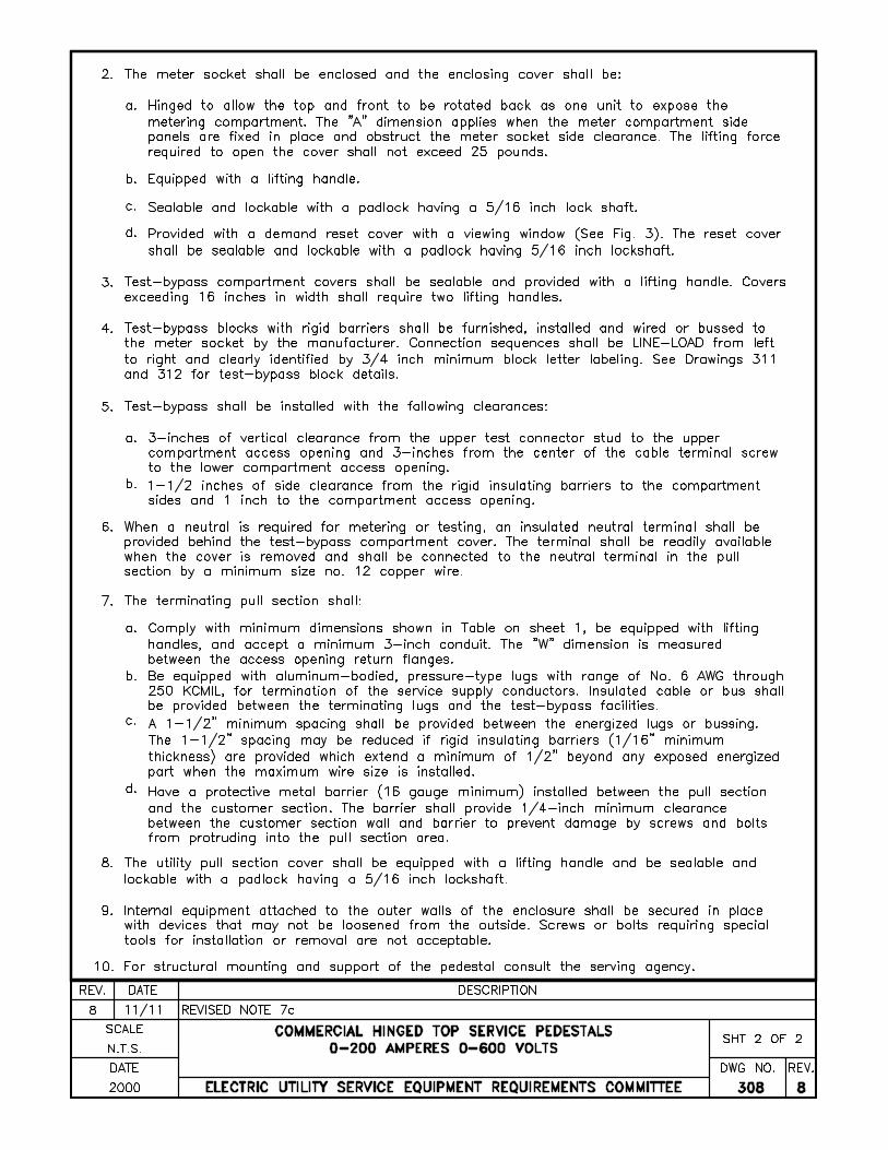
B. Commercial, General
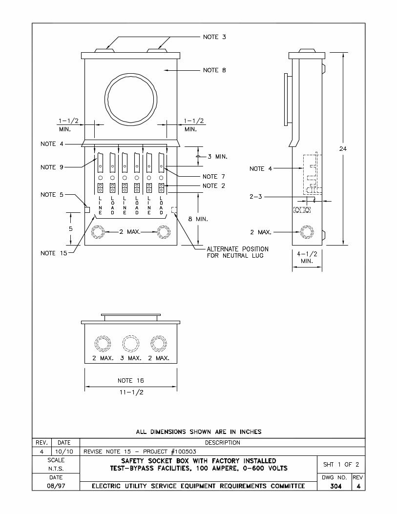
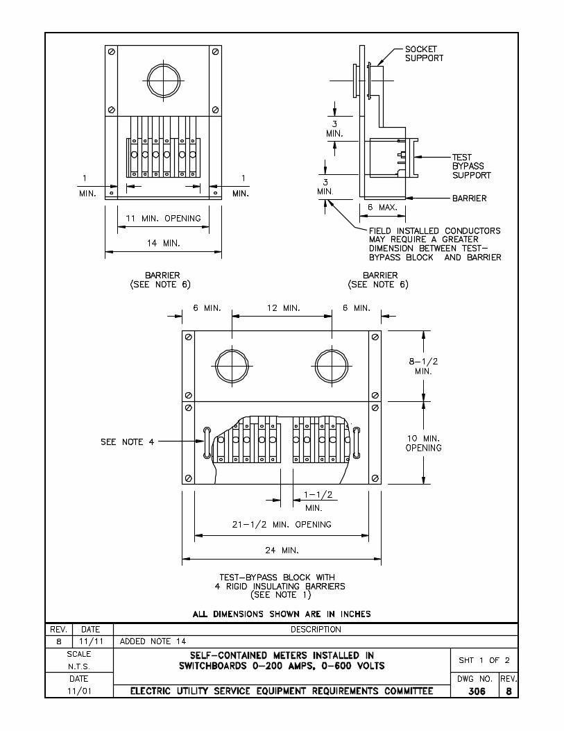
Class 100 or 200 socket-type meters are commonly used and test-bypass disconnect facilities are required for this application. Some utilities allow Class 320 or Class 400 amp meters for specialized installations (Go to www.euserc.com for specific utility requirements).
C. Multiple, Switchboard 1. The socket and socket enclosure shall be designed in accordance with the latest revision of
AEIC-EEI-NEMA Standards for Watthour Meter Sockets, Publication ANSI C12.7, and with standard for Meter Sockets UL414.
2. The bussing or cables to each individual meter socket are to be installed so they can be
visibly traced. 3. Multiple meter enclosures that are not factory bussed shall have nonremovable, solid metal
barriers, to isolate the metered conductors from the unmetered conductors.
EUSERC Drawing 300
Sheet 7
4. The service termination enclosure, socket enclosures, raceways and sections for test-bypass or manual circuit closing facilities shall have separate, removable and sealable access panels (or plates). Meter socket enclosures shall have a separate sealable cover containing no more than two meter positions.
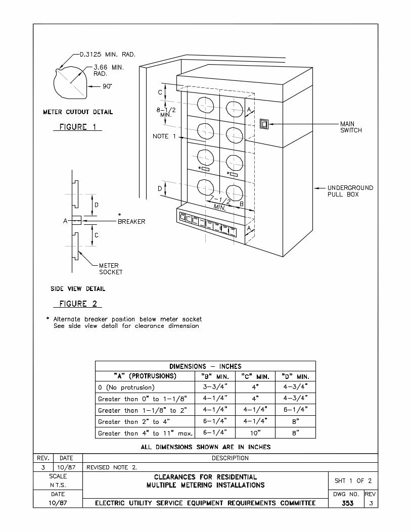
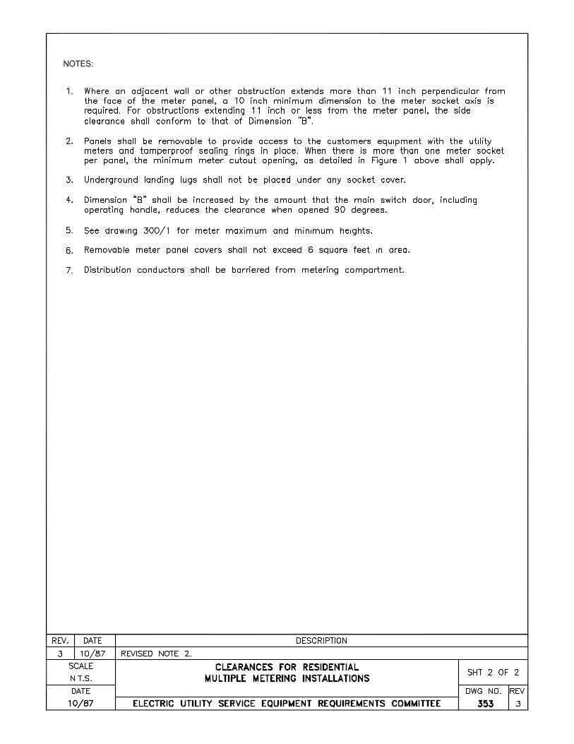
D. Meter Spacing and Clearances
1. The rules for spacing of socket meters in multiple residential meter installations shall be as follows: Horizontal spacing - 7 1/2 inches minimum on centers. Vertical spacing - 8 1/2 inches minimum on centers.
2. See Drawing 353 for Multiple Meter clearances.
E. Apartment Metering Excluding Switchboards 1. Where a large number of apartments in one building are to be individually metered, a
combination of service termination, raceway and meter enclosures may be used. (Consult local utility for approval).
2. When these units are constructed with metered and unmetered conductors in the same
raceway behind adjacent meter sockets, the serving agency will require the following additional specifications.
a. Metered and unmetered conductors shall be separated so that it is readily apparent that
all of the load is being metered (line and load conductors not cabled together). b. Factory "harness-style" wiring (or equivalent) shall be used between the line wireway
and the line terminals of each meter socket and also between the load terminals of each meter socket and the line side of the corresponding circuit breaker.
c. Connecting wires between meter socket load terminals and circuit breaker line
terminals shall be separately cabled for each position in the row. d. When the installation is completed, all panels must be removable for inspection of
wiring. e. Panel design shall permit convenient replacement of any individual meter socket.
3. See installation guides for typical arrangements.
IV. TRANSFORMER RATED METERING INSTALLATIONS A. General Requirements
1. Instrument transformer compartments are generally required when the connected load exceeds 200 amperes. See Section 200 for exceptions and utility acceptability of these requirements and Section 400 when the voltage between conductors exceeds 600 volts.
2. Meter, instrument transformers and test switches will normally be furnished and installed
by the serving agency. Any required conduits or raceways shall be furnished and installed by the switchboard manufacturer or contractor, (See Section 200 for specific utility requirements).
EUSERC Drawing 300
Sheet 8
3. All compartments containing unmetered conductors shall be sealable. When a raceway or conduit for meter secondary wiring is necessary, such raceway or conduit shall be sealable.
B. Switchboard Service Sections, General 1. For both standard and specially engineered switchboard service sections, all service or
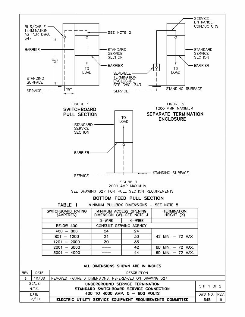
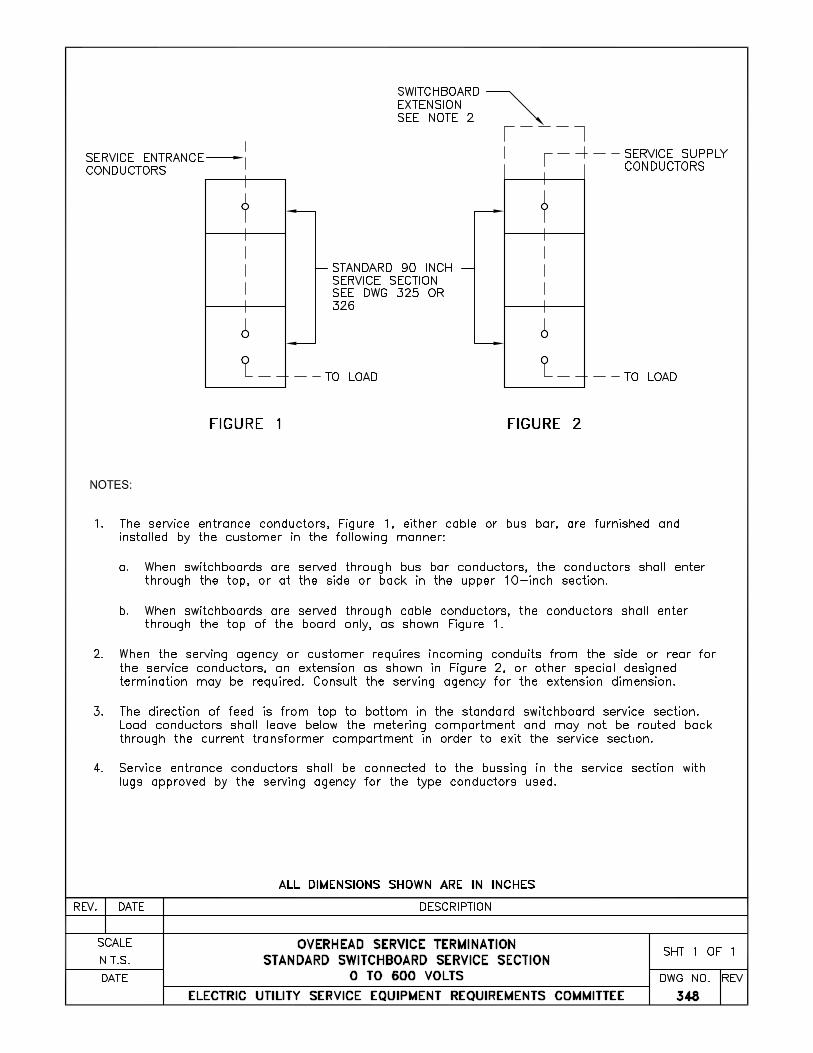
supply conductors shall enter the service section through one end and leave through the opposite end of the instrument transformer compartment. This stipulation applies to either overhead or underground service or if two or more service sections are connected together. The direction of feed shall be vertical through the instrument transformer compartment, (See Drawing 345).
2. When more than one switchboard service section is installed, each service section shall be
completely barriered from other service sections, pull sections, or service switches or disconnects. Barriers may have an opening to allow passage of un-metered conductors between sections.
Note 1: The barrier between sealed utility metering sections and the pull section may be
1/8” minimum glastic or equivalent. Note 2: The clearance between bus bar and glastic shall be a maximum of 3”. No barrier
shall be required between individual phases and neutral. 3. Except where otherwise specified in these requirements, barriers used in switchboard
installations to separate customer sections from utility sections (i.e., pull sections and metering sections) and sections containing unmetered conductors or bus shall be constructed from 16 gauge (minimum) steel and shall be secured with devices that are not removable from either the customer sections or the exterior of the switchboard.
4. When two or more switchboard service sections are supplied from one set of service
conductors, the supply conductors are to be arranged so they are readily accessible without disturbing the instrument transformers and associated secondary wiring.
5. Additional service connections may be made in the main service termination and pull
section where more than one metering installation is necessary, or where more than one rate schedule is desired. Additional service connections shall not be made in the instrument transformer compartment. Consult serving agency for approval.
6. Meter installations of six meters or less shall be connected "new sequence". Consult
serving agency for exceptions.
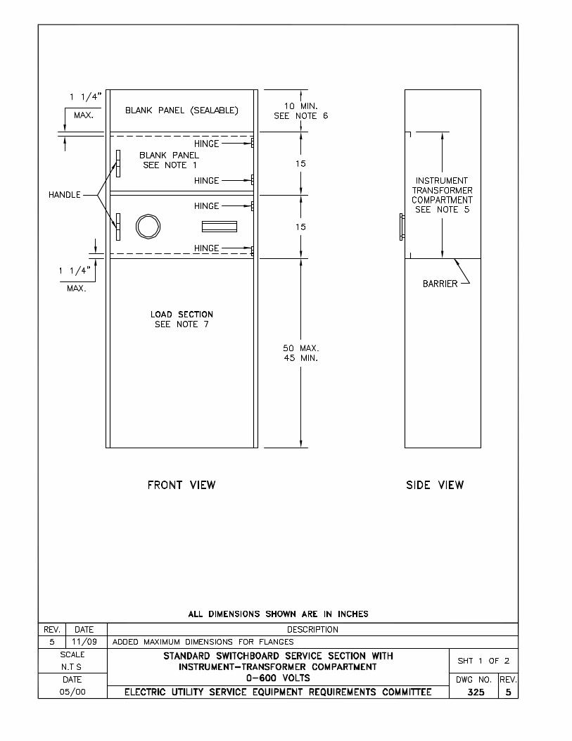
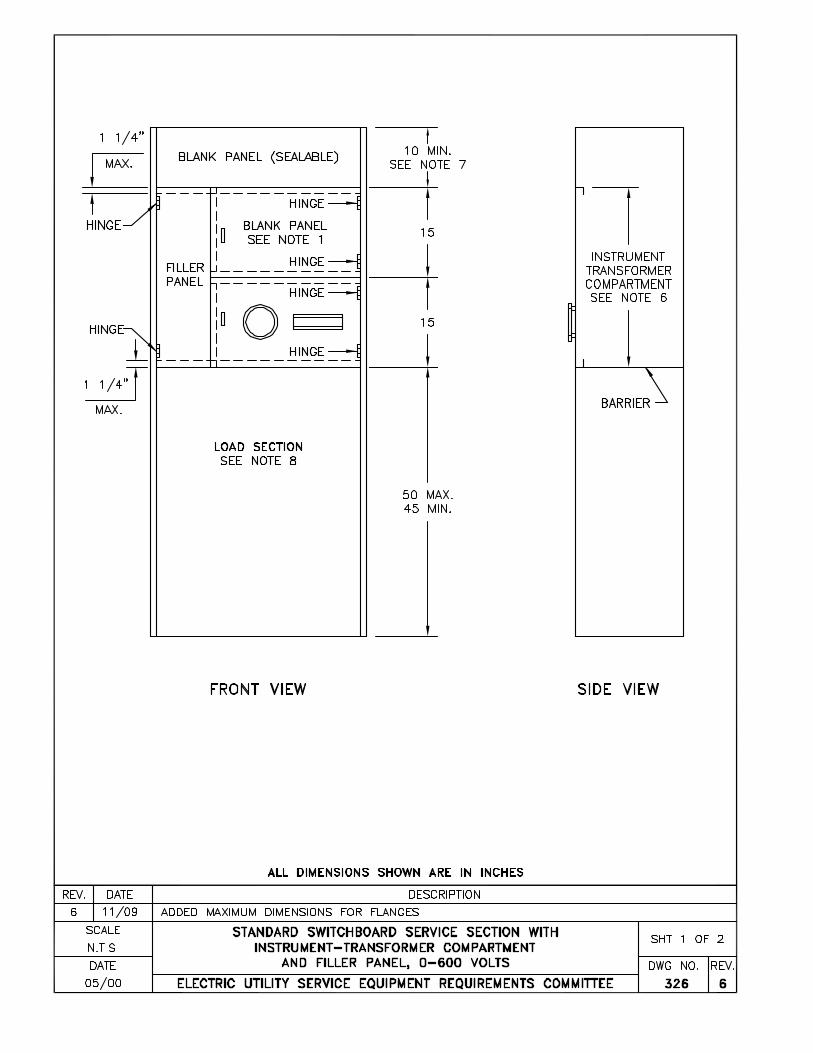
C. Standard Switchboard Service Section 1. The general arrangement of a standard switchboard section is shown on Drawings 325 and
326. 2. A standard switchboard service section has a hinged meter panel located in front of the
instrument transformer compartment. Drawing 333 shows spacings for various combinations of multiple meters.
3. Hinged meter panels must have handles and open a minimum of 90 degrees with meters
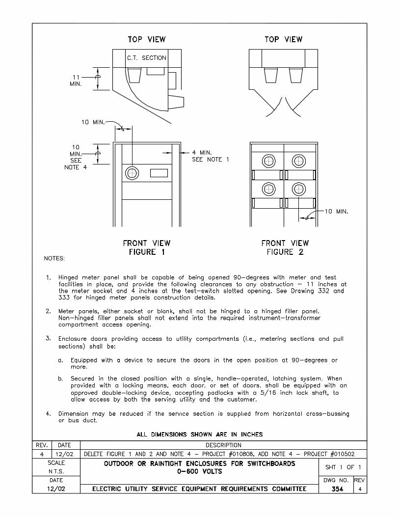
and test switches mounted to permit safe and ready access to the instrument transformers. When hinged panels are recessed, the section shall have additional width to meet this requirement. A recessed panel requires utility approval as a specially engineered section, (see Drawing 354).

EUSERC Drawing 300
Sheet 9
4. Hinged meter panels must be sealable and easily removable, with the hinges readily interchangeable from the right or left side on the job site.
5. The hinged meter panels on Drawings 332 and 333 are designed for transformer-rated,
socket-type meters.
EUSERC Drawing 300
Sheet 10
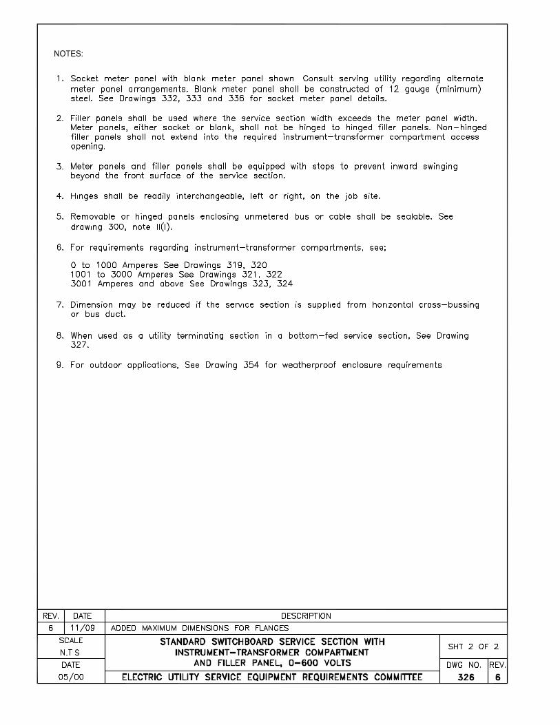
6. Meter panels and filler panels shall be equipped with stops to prevent inward swinging beyond the front surface of the switchboard.
7. Not more than two meters shall be mounted on any removable meter panel. 9. For hinged socket meter panels, see Drawings 332 and 333. 9. For underground service application of Standard Switchboard Service Sections, see
Drawing 345.
D. Specially Engineered Service Sections 1. Switchboards which do not conform to standard design criteria are considered specially
engineered and include installations: a. Rated over 3000 amperes or 600 volts. b. Where the service breaker ampacity rating exceeds that of the standard service section. c. Where multiple metering sections are used. d. Where recessed meter panels are used.
2. When a specially engineered service section is necessary, drawings in triplicate of the proposed section shall be submitted to the serving agency for approval prior to manufacture and bidding. Such drawings shall indicate the contractor's and the customer's name and address and job location.
3. The general arrangement of Specially Engineered Switchboard Service Sections should
follow, as nearly as practicable, that of the Standard Switchboard Service Sections, and the following general requirements shall be observed: a. Instrument transformer-rated socket meters, used with current transformers, are
normally mounted on hinged panels. b. If a hinged meter panel is located behind a door, a clear space of at least 11 inches
between the meter panel and the door is required, and shall be designed to open 90 degrees with meters and test switches in place. If needed, additional section width shall be provided to meet this requirement.
c. A clear space in back of a meter panel shall be provided for the secondary wiring and
phase shifting device. For minimum dimensions between the hinged meter panel and the nearest bus, see Drawings 319 through 324.
d. For nonhinged meter panels, a clear space of four inches minimum to any barrier or
obstruction shall be provided. e. The nonhinged meter panels shall not be used in front of a current transformer section.
For a specially engineered switchboard, nonhinged panels will accommodate socket-type instrument transformer-rated meters.
f. For minimum clearance between meters, (see Drawings 306, 333, 336, and 353). g. Additional panel space is required for recording or graphic demand meters, see
Drawing 333.
EUSERC Drawing 300
Sheet 11
h. Not more than two meters shall be mounted on any removable meter panel. i. Busses shall be adequately supported in the metering transformer compartment to
withstand the mechanical stresses of a short circuit. The bus supports shall not interfere with installation or removal of current transformers. Current transformers shall not be used to support the busses. The busses shall be entirely self-supporting.
j. The busses and current transformer mountings shall be designed so that each of the
current transformers may be withdrawn from its mounting position directly through the access panel without disturbing any other current transformer. When multi-leaf busses are used, the busses shall be oriented so that they appear "edgewise" when viewed from the access panel.
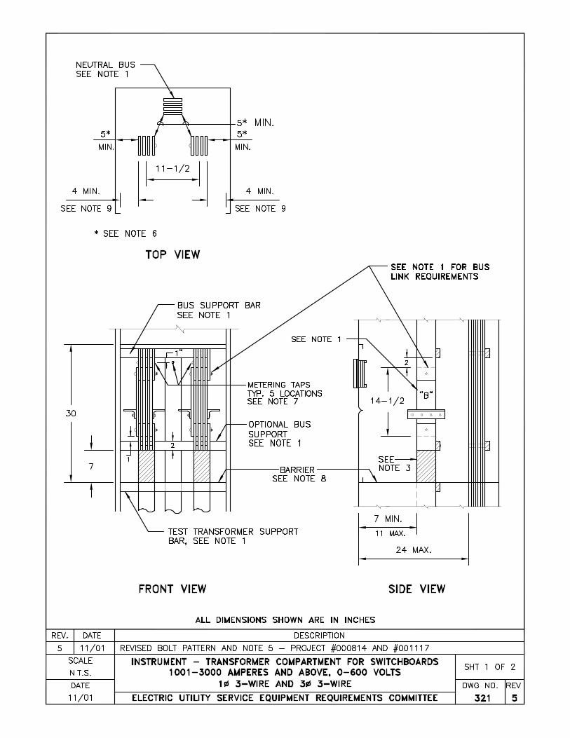
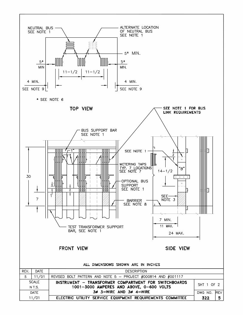
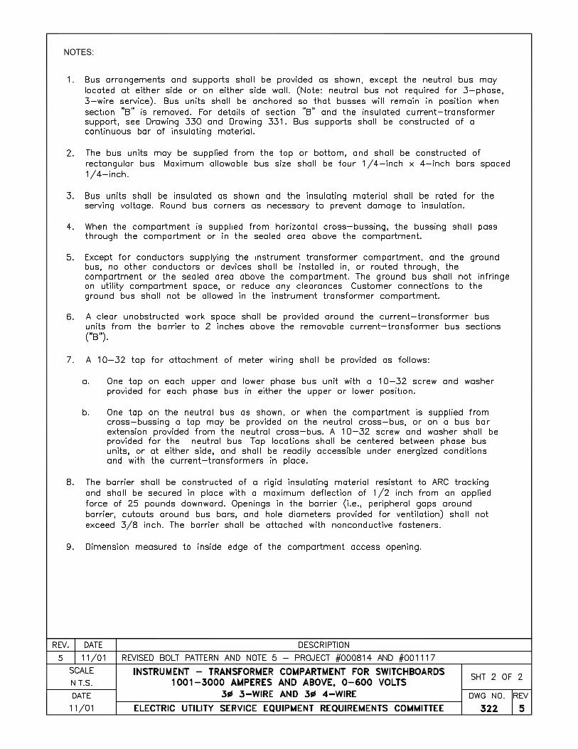
E. Instrument-Transformer Compartments
1. For details of instrument transformer compartments, see Drawings 319 through 322. 2. Covers for instrument transformer compartments shall be made of code gauge metal; if
nonhinged panels are used as covers, they shall be provided with lifting handles and be attached with sealable studs and wing-nuts or by other approved means.
3. Copper or aluminum bus bar shall be used on both the line and load sides of all current
transformers. When aluminum bus is used, the bus bars shall be plated, (see Bus Bar Plating, Drawing 300).
4. When the serving agency requests links and supports for through-type current transformer,
the bus and removable links must be of a compatible material. 5. Instrument transformers supplied by the serving agency for metering shall not be utilized
for any other purpose 6. The ends of the current transformer bus stubs shall be located so the current transformers
can be installed without removing adjacent panels. 7. The current transformer bus stub supports in the instrument transformer compartment shall
be sufficiently rigid to maintain alignment of the bus when the conductors are installed. The current transformers or bus links shall not provide bus support or alignment.
8. Except for factory-installed cross-bussing and conductors, either bus or cable, used to
supply the instrument-transformer compartment, no other conductors or devices shall be installed in the instrument-transformer compartment or in the sealed area above the instrument-transformer compartment.
EUSERC Drawing 300
Sheet 12
V. SERVICE TERMINATION EQUIPMENT, GENERAL A. Switchboards Excluded
This paragraph of the Requirements applies to all meter and service equipment when not installed on switchboards. 1. General
a. Service termination facilities shall be specifically designed to receive the serving
agency's underground service lateral conductors as a single cable entry. Enclosures designed for either overhead or underground cable entry are acceptable provided they meet requirements for both types of cable entry.
b. Service cable termination lugs or connectors shall be suitable for use with both
aluminum and copper conductors. The serving agency should be consulted for specific lug or connector requirements.
c. Socket enclosures designed for single sockets rated up to, and including 200 amperes,
shall have service terminating lugs independently mounted from the socket jaw support.
d. Tests for meter sockets shall be in accordance with the current Standard for Meter
Sockets UL414. e. Service terminating space in enclosures rated greater than 200 amperes with multiple
meter sockets shall accommodate either compression-type lugs or screw-type mechanical landing lugs. All bussing or cable conductors beyond the terminating lugs shall be provided by the manufacturer or the customer's contractor. Bus stubs or bussing in the service terminating space used for terminating the utility service lateral shall have mounting bolts spaced in accordance with NEMA Standards. For termination bus detail, see Drawing 343.
f. The service cable termination compression lugs, or screw type mechanical lugs shall be
compatible with the size and type of service being installed (i.e., aluminum-bodied AL-CU with aluminum cables, etc.). The termination lug landings for the neutral and each phase conductor shall be rigidly and permanently affixed in the service termination space and all grouped at one location.
g. Wireways in the service termination space designed for terminating the utility service
lateral shall be clearly identified for such use. Service termination shall be made in the service termination enclosure or in specially designated space of a meter panel which has a separate removable and sealable access plate.
h. The layout or design of the service termination enclosure that requires bending the
utility service conductors, should provide space to permit a minimum cable bending radius equal to four times the overall diameter of the cable measured from the inner surface of the cable (from Minimum Bending Radius for Thermo-Plastic Insulated Cables, IPCEA S-61-402 and NEMA WC-5-1961 Standards).
NOTE: The overall termination enclosure size is not predicated solely on the cable bending radius. Adequate working space and electrical clearances are also considered in establishing enclosure dimensions in these requirements.
EUSERC Drawing 300
Sheet 13
i. The service termination enclosure, socket enclosure and test-bypass disconnect block section shall be sealable and isolated or barriered from other integral enclosure sections which are accessible to the customer in order to effectively prevent unauthorized connections to unmetered conductors or terminals.
j. The manufacturer's rating label, or other markings used in lieu of a label, shall show
among other things:
(1) Whether the socket or socket enclosure is designed for overhead service entry, underground service entry, or both.
(2) That the terminating lugs are designed for both aluminum and copper conductors. (3) The wire size range of the termination lugs.
2. Single Self-Contained Meter Termination, Underground Service
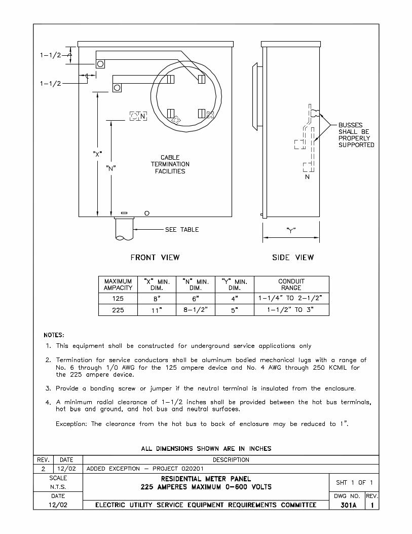
a. The socket and enclosure shall be specifically designed to receive service cables from
an underground supply system. Separate service terminating lugs supported independent of the socket and connected to it by bus bars are required for single family residential meter socket enclosures. (See Drawing 301.)
b. Wiring space for service lateral conductors shall be clearly identified as intended for
such use, shall be clear of all projections and shall be used exclusively for such purposes.
c. A separate removable cover, independent of the meter panel, is required in front of the
pull section, (see Drawing 301.) d. Knockouts in cable wireways shall be positioned to minimize service lateral cable
bending. e. The service cable entry section and the meter socket section shall be sealable and
isolated or barriered from other integral enclosure sections which are accessible to the customer in order to effectively prevent the attachment of unauthorized connections to unmetered conductors or terminals.
f. The load wires from the distribution section (branch circuits) shall not pass through
any sealable section.
3. Multiple Self-Contained Meter Termination, Underground Service a. When self-contained meters are installed on switchboards, the service termination
requirements for switchboards shall be followed (see Switchboards). b. When self-contained meters are installed in multiple arrangements, in separate meter
enclosures, the GENERAL service equipment requirements shall be followed. (See Drawing 343 for termination enclosure requirements and installation guides section for typical arrangements).
EUSERC Drawing 300
Sheet 14
B. Switchboards 1. Switchboard Termination, Underground Service
a. For underground services, the serving agency will terminate its service conductors on
lug landings at the current transformer bus stubs only when the service is a single-meter installation and the switchboard is rated 400 amperes or less.
NOTE: Some utilities require the service conductors to be terminated in the pull section for switchboards rated less than 400 amperes.
(1) The serving agency will terminate its service conductors on lug landings in the
pull section when the service is for multiple metering or the switchboard is rated 401 amperes or larger, (see Figure 1 on Drawing 345). (a) On switchboards rated 401-800 amperes, the customer shall install
conductors from the service termination lug landings to the line side of the current transformer compartment.
(b) On switchboards rated 800 amperes, or with multiple meters, bus bars shall
extend from the service terminating lug landings into the current transformer compartment or the meter sockets.
2. Switchboard Termination, Overhead
For overhead services, the customer shall furnish lugs and connect the cable to line and load sides of the bus stubs in the current transformer compartment, (see Drawing 348).


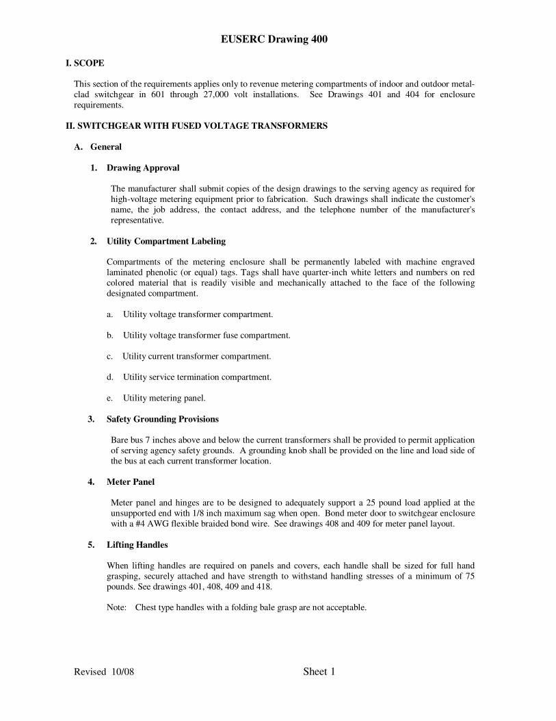
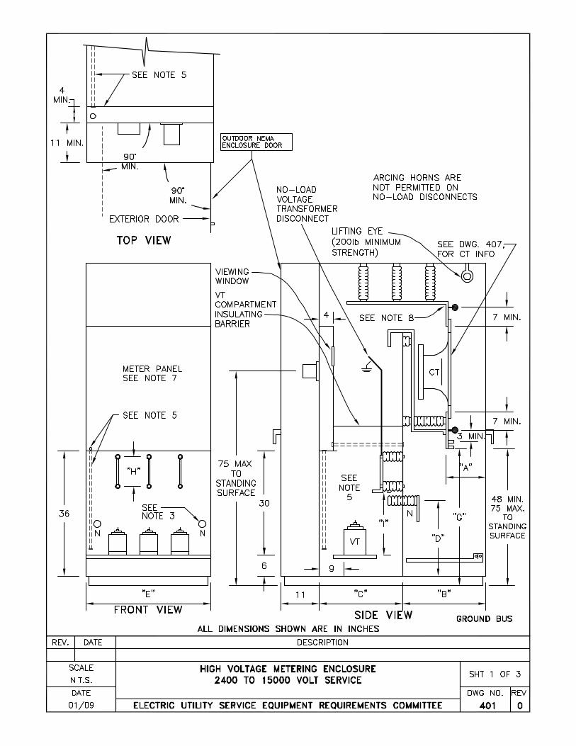
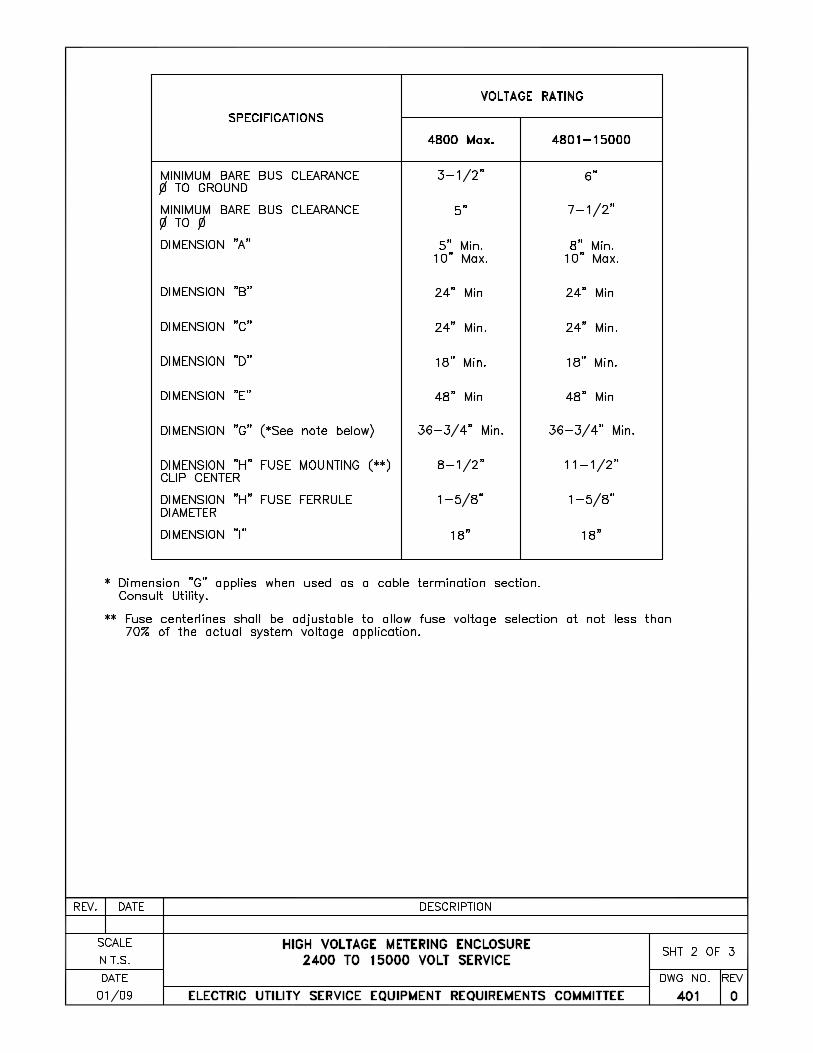
EUSERC Drawing 400
I. SCOPE
This section of the requirements applies only to revenue metering compartments of indoor and outdoor metal-
clad switchgear in 601 through 27,000 volt installations. See Drawings 401 and 404 for enclosure
requirements.
II. SWITCHGEAR WITH FUSED VOLTAGE TRANSFORMERS
A. General
1. Drawing Approval
The manufacturer shall submit copies of the design drawings to the serving agency as required for
high-voltage metering equipment prior to fabrication. Such drawings shall indicate the customer's
name, the job address, the contact address, and the telephone number of the manufacturer's
representative.
2. Utility Compartment Labeling
Compartments of the metering enclosure shall be permanently labeled with machine engraved
laminated phenolic (or equal) tags. Tags shall have quarter-inch white letters and numbers on red
colored material that is readily visible and mechanically attached to the face of the following
designated compartment.
a. Utility voltage transformer compartment.
b. Utility voltage transformer fuse compartment.
c. Utility current transformer compartment.
d. Utility service termination compartment.
e. Utility metering panel.
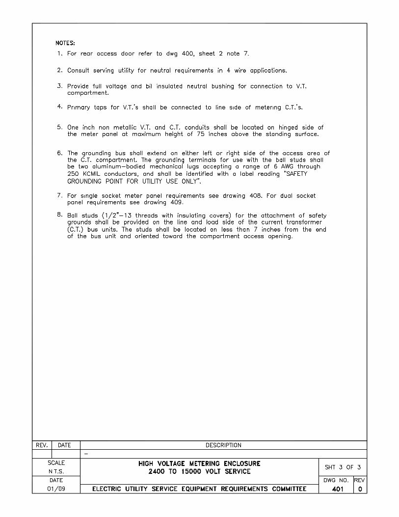
3. Safety Grounding Provisions
Bare bus 7 inches above and below the current transformers shall be provided to permit application
of serving agency safety grounds. A grounding knob shall be provided on the line and load side of
the bus at each current transformer location.
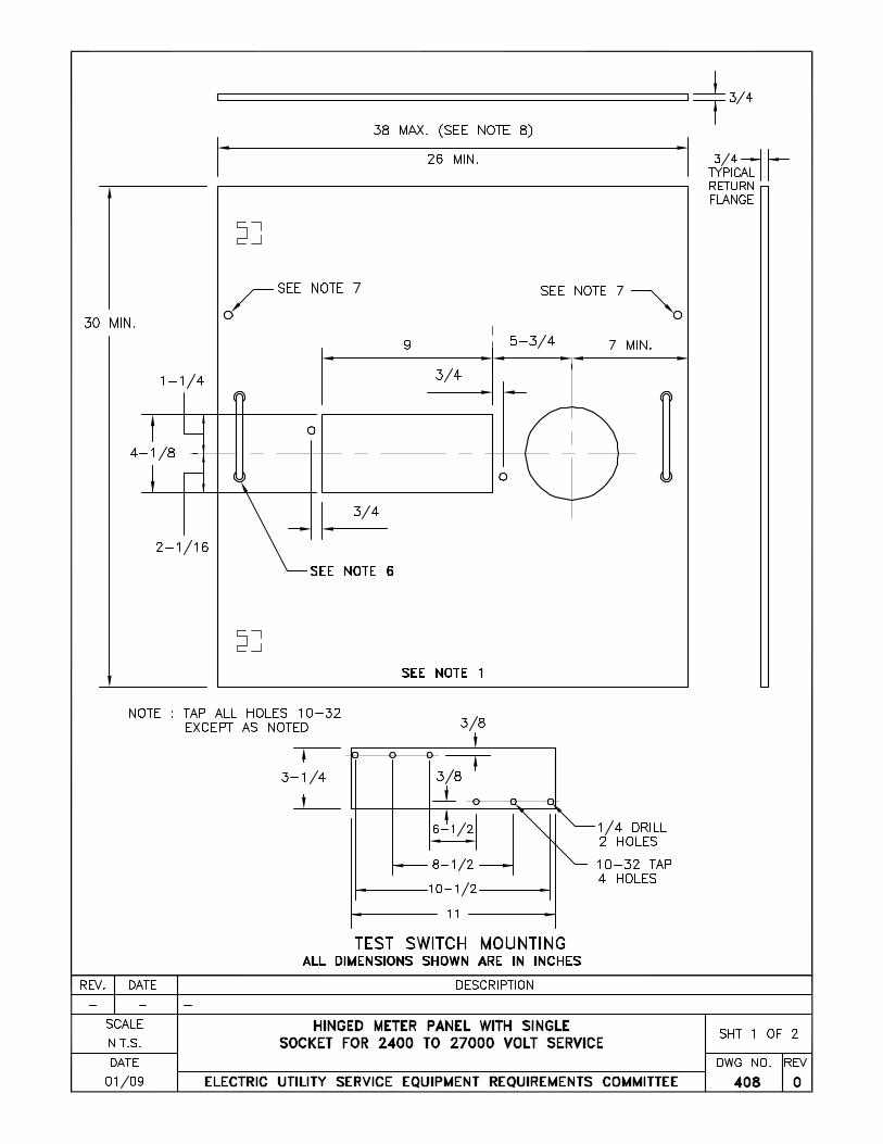
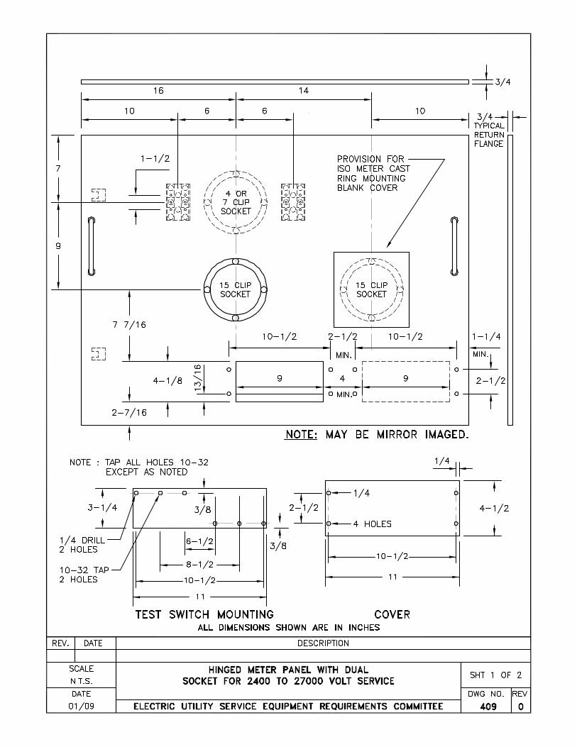
4. Meter Panel
Meter panel and hinges are to be designed to adequately support a 25 pound load applied at the
unsupported end with 1/8 inch maximum sag when open. Bond meter door to switchgear enclosure
with a #4 AWG flexible braided bond wire. See drawings 408 and 409 for meter panel layout.
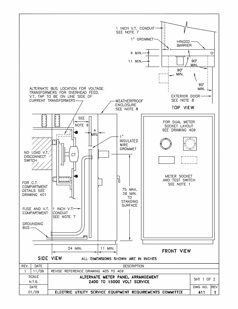
5. Lifting Handles
When lifting handles are required on panels and covers, each handle shall be sized for full hand
grasping, securely attached and have strength to withstand handling stresses of a minimum of 75
pounds. See drawings 401, 408, 409 and 418.
Note: Chest type handles with a folding bale grasp are not acceptable.
Revised 10/08 Sheet 1
EUSERC Drawing 400
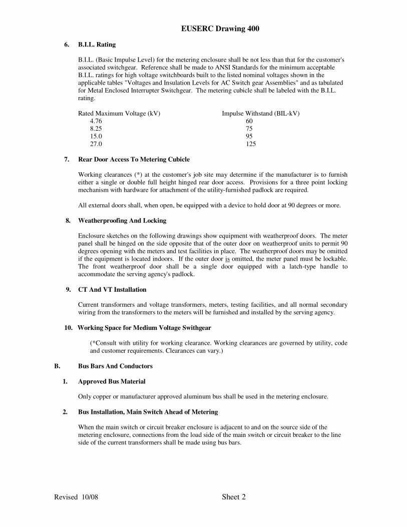
6. B.I.L. Rating
B.I.L. (Basic Impulse Level) for the metering enclosure shall be not less than that for the customer's
associated switchgear. Reference shall be made to ANSI Standards for the minimum acceptable
B.I.L. ratings for high voltage switchboards built to the listed nominal voltages shown in the
applicable tables "Voltages and Insulation Levels for AC Switch gear Assemblies" and as tabulated
for Metal Enclosed Interrupter Switchgear. The metering cubicle shall be labeled with the B.I.L.
rating.
Rated Maximum Voltage (kV) Impulse Withstand (BIL-kV)
4.76 60 8.25 75
15.0 95
27.0 125
7. Rear Door Access To Metering Cubicle
Working clearances (*) at the customer's job site may determine if the manufacturer is to furnish
either a single or double full height hinged rear door access. Provisions for a three point locking
mechanism with hardware for attachment of the utility-furnished padlock are required.
All external doors shall, when open, be equipped with a device to hold door at 90 degrees or more.
8. Weatherproofing And Locking
Enclosure sketches on the following drawings show equipment with weatherproof doors. The meter
panel shall be hinged on the side opposite that of the outer door on weatherproof units to permit 90
degrees opening with the meters and test facilities in place. The weatherproof doors may be omitted
if the equipment is located indoors. If the outer door is omitted, the meter panel must be lockable.
The front weatherproof door shall be a single door equipped with a latch-type handle to
accommodate the serving agency's padlock.
9. CT And VT Installation
Current transformers and voltage transformers, meters, testing facilities, and all normal secondary
wiring from the transformers to the meters will be furnished and installed by the serving agency.
10. Working Space for Medium Voltage Swithgear
(*Consult with utility for working clearance. Working clearances are governed by utility, code
and customer requirements. Clearances can vary.)
B. Bus Bars And Conductors
1. Approved Bus Material
Only copper or manufacturer approved aluminum bus shall be used in the metering enclosure.
2. Bus Installation, Main Switch Ahead of Metering
When the main switch or circuit breaker enclosure is adjacent to and on the source side of the
metering enclosure, connections from the load side of the main switch or circuit breaker to the line
side of the current transformers shall be made using bus bars.
Revised 10/08 Sheet 2
EUSERC Drawing 400
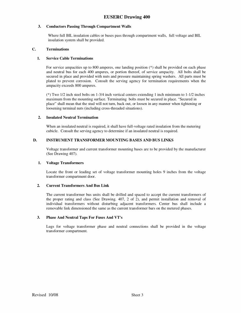
3. Conductors Passing Through Compartment Walls
Where full BIL insulation cables or buses pass through compartment walls, full voltage and BIL
insulation system shall be provided.
C. Terminations
1. Service Cable Terminations
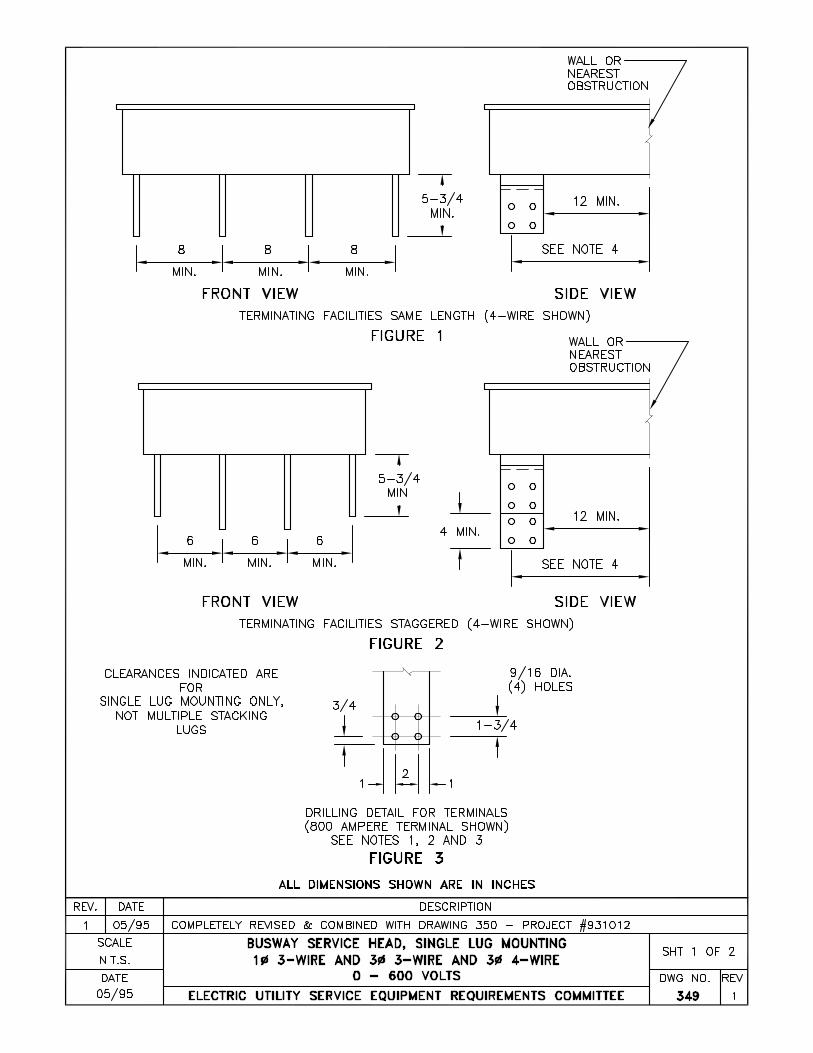
For service ampacities up to 800 amperes, one landing position (*) shall be provided on each phase
and neutral bus for each 400 amperes, or portion thereof, of service ampacity. All bolts shall be secured in place and provided with nuts and pressure maintaining spring washers. All parts must be
plated to prevent corrosion. Consult the serving agency for termination requirements when the
ampacity exceeds 800 amperes.
(*) Two 1/2 inch steel bolts on 1-3/4 inch vertical centers extending 1 inch minimum to 1-1/2 inches
maximum from the mounting surface. Terminating bolts must be secured in place. “Secured in
place” shall mean that the stud will not turn, back out, or loosen in any manner when tightening or
loosening terminal nuts (including cross-threaded situations).
2. Insulated Neutral Termination
When an insulated neutral is required, it shall have full-voltage rated insulation from the metering
cubicle. Consult the serving agency to determine if an insulated neutral is required.
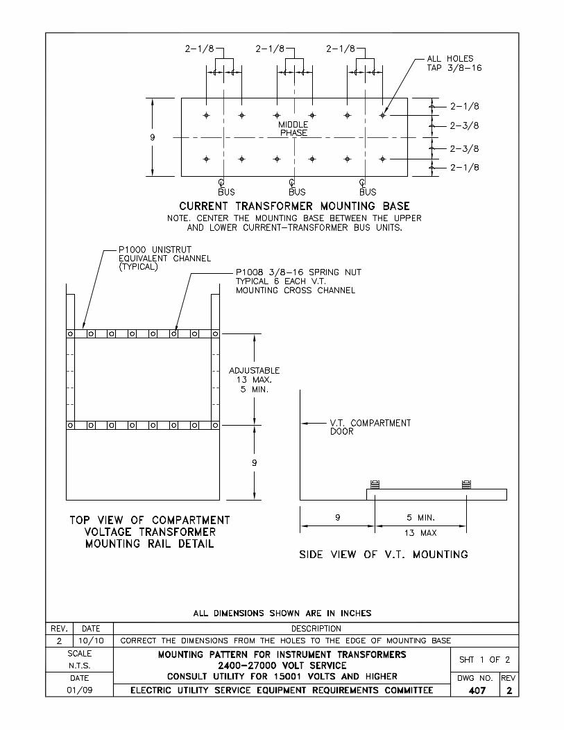
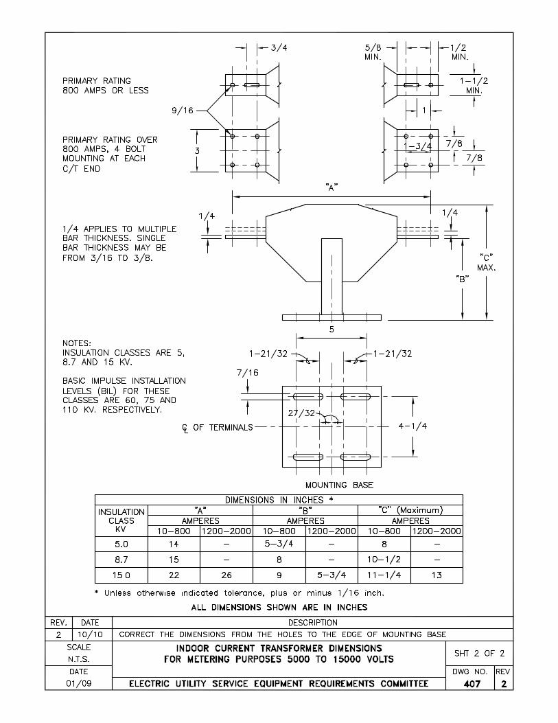
D. INSTRUMENT TRANSFORMER MOUNTING BASES AND BUS LINKS
Voltage transformer and current transformer mounting bases are to be provided by the manufacturer
(See Drawing 407).
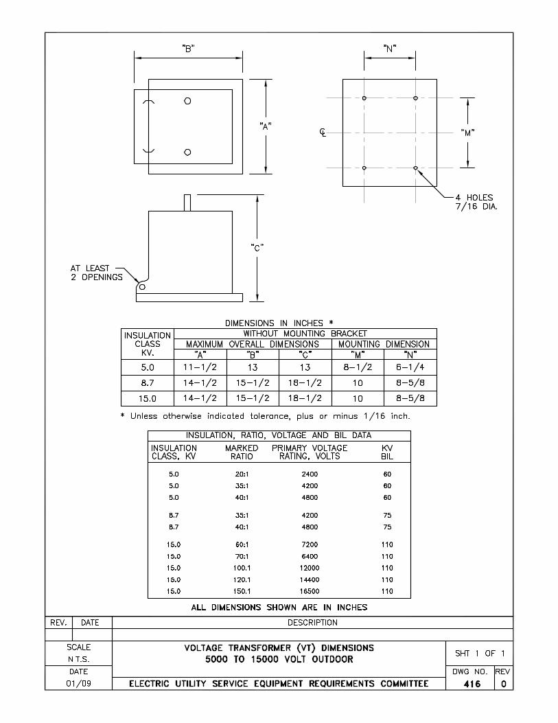
1. Voltage Transformers
Locate the front or leading set of voltage transformer mounting holes 9 inches from the voltage
transformer compartment door.
2. Current Transformers And Bus Link
The current transformer bus units shall be drilled and spaced to accept the current transformers of
the proper rating and class (See Drawing. 407, 2 of 2), and permit installation and removal of
individual transformers without disturbing adjacent transformers. Center bus shall include a
removable link dimensioned the same as the current transformer bars on the metered phases.
3. Phase And Neutral Taps For Fuses And VT's
Lugs for voltage transformer phase and neutral connections shall be provided in the voltage transformer compartment.
Revised 10/08 Sheet 3
EUSERC Drawing 400
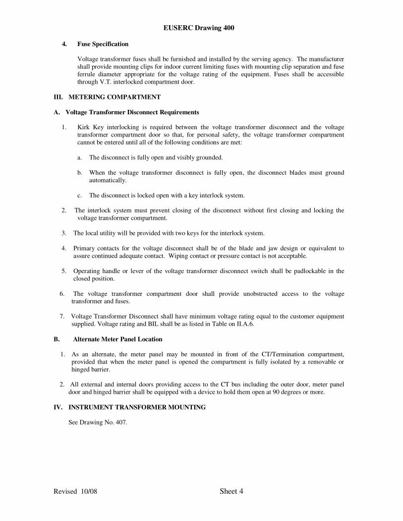
4. Fuse Specification
Voltage transformer fuses shall be furnished and installed by the serving agency. The manufacturer
shall provide mounting clips for indoor current limiting fuses with mounting clip separation and fuse
ferrule diameter appropriate for the voltage rating of the equipment. Fuses shall be accessible
through V.T. interlocked compartment door.
III. METERING COMPARTMENT
A. Voltage Transformer Disconnect Requirements
1. Kirk Key interlocking is required between the voltage transformer disconnect and the voltage
transformer compartment door so that, for personal safety, the voltage transformer compartment
cannot be entered until all of the following conditions are met:
a. The disconnect is fully open and visibly grounded.
b. When the voltage transformer disconnect is fully open, the disconnect blades must ground
automatically.
c. The disconnect is locked open with a key interlock system.
2. The interlock system must prevent closing of the disconnect without first closing and locking the
voltage transformer compartment.
3. The local utility will be provided with two keys for the interlock system.
4. Primary contacts for the voltage disconnect shall be of the blade and jaw design or equivalent to
assure continued adequate contact. Wiping contact or pressure contact is not acceptable.
5. Operating handle or lever of the voltage transformer disconnect switch shall be padlockable in the
closed position.
6. The voltage transformer compartment door shall provide unobstructed access to the voltage transformer and fuses.
7. Voltage Transformer Disconnect shall have minimum voltage rating equal to the customer equipment
supplied. Voltage rating and BIL shall be as listed in Table on II.A.6.
B. Alternate Meter Panel Location
1. As an alternate, the meter panel may be mounted in front of the CT/Termination compartment,
provided that when the meter panel is opened the compartment is fully isolated by a removable or
hinged barrier.
2. All external and internal doors providing access to the CT bus including the outer door, meter panel
door and hinged barrier shall be equipped with a device to hold them open at 90 degrees or more.
IV. INSTRUMENT TRANSFORMER MOUNTING
See Drawing No. 407.
Revised 10/08 Sheet 4

EUSERC Drawing 400
V. FUSE SPECIFICATION
Voltage transformer fuses shall be furnished and installed by the serving agency. The manufacturer
shall provide mounting clips for indoor current limiting fuses with mounting clip separation and fuse
ferrule diameter dimensions as shown on drawings No. 401 and 404.
VI. MEETING COMPARTMENT (27,000 VOLTS SERVICE)
A. Vertical busing in the pull section and C.T. compartment shall be spaced 18 inches on centerline
between phases, and the center phase shall be on the enclosure centerline.
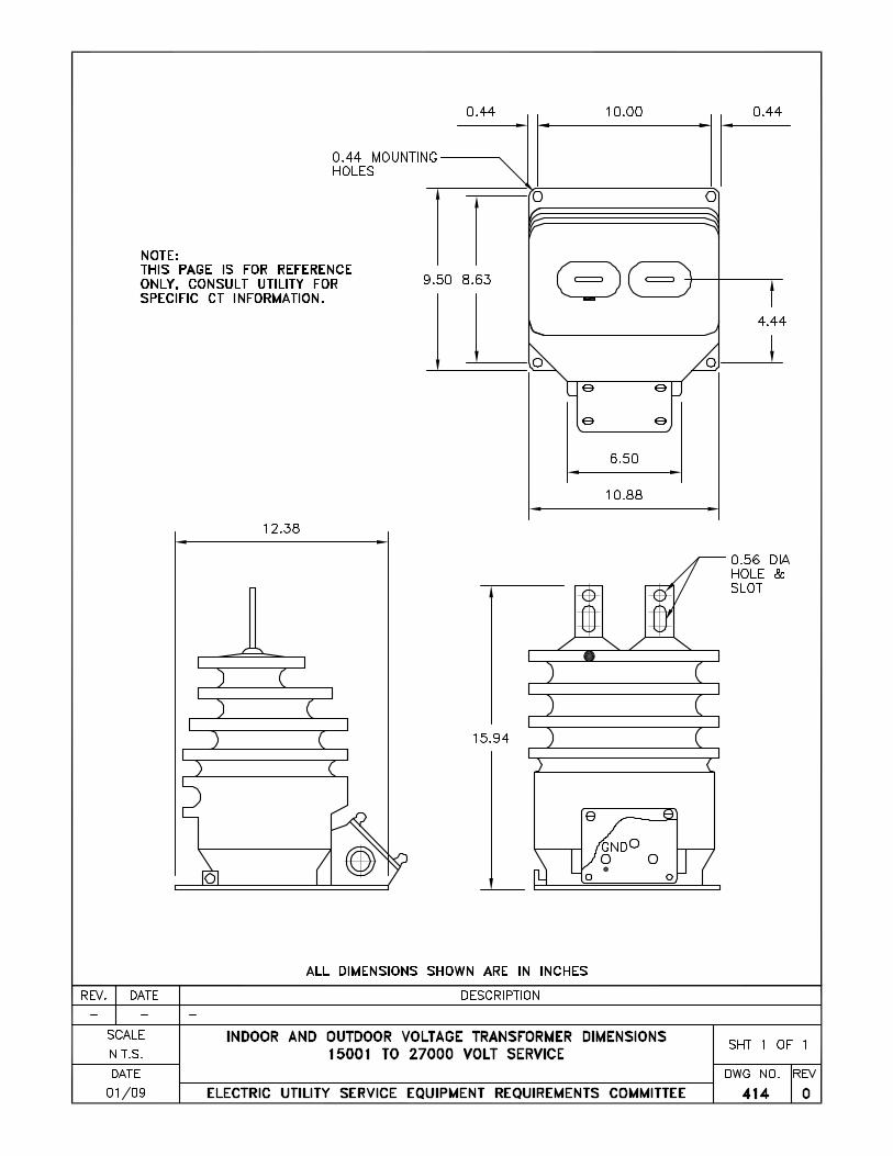
B. Current and voltage transformers will be outdoor type. Provide transformer mounting bases and
busing configuration (in the C.T. compartment) to accommodate this style transformer. Consult
utility for manufacturer catalog number and obtain C.T. drawing.
Revised 10/08 Sheet 5