Electrical Power & Machines Range 60-070 - Feedback
22
Page 1 of 22 12/2013 Electrical Power & Machines Range 60-070 Electrical Power and Machines is one of the most important areas of study for stu- dents in further and higher education. As we become more aware of the finite energy resources available to us it is im- perative that we use them in the most effi- cient manner. Engineers and technicians need to know which machines and motors are best suited for particular applications, how to generate and distribute power with the minimum losses and how electrical circuits behave at higher voltages and cur- rents. For example would the same type of motor be ideal for use in a DVD Drive as might be required for a power tool or a locomotive? How can we distribute and utilise the maximum amount of power? Why do we use Three Phase electrical power generation? Feedback Instruments Limited has been supplying teaching and training systems to educational establish- ments throughout the World since 1958. Using the experience we have gained, we have configured a teaching system for Electrical Power and Machines which addresses the requirements of colleges and uni- versities and enables students to get a “hands-on” understanding in these subjects. This datasheet describes the modular 60-070 system which provides curriculum coverage for Electrical Circuits, Transformers and Motors and Generators. From our knowledge of the market we believe that the standard configurations described here will satisfy the needs of most courses at different academic levels. However, the system is modular and can be configured to suit individual requirements. The 60-070 and all the other products in the complete Electrical Power and Machines range are available for operation with three phase 230/400 V 50 Hz or 120/208 V 60 Hz supplies. Please specify clearly when ordering which supply you will be using. Features • d.c. Machines • Single Phase Machines • Three Phase Machines • Electrical Circuits • Single Phase Transformers • Three Phase Transformers • Electromagnetic Motor Control • d.c. Motor Speed Control • a.c. Motor Speed Control • Measuring Instruments System Benefits • Low cost start-up • Core system can be extended • High level of electrical and mechanical safety built-in • Low cost installation - suitable for bench-top use • Easily portable machines and system components • Modular concept provides flexibility for individual requirements • Choice of conventional or virtual instruments • All products provide with in-depth teaching manuals
Transcript of Electrical Power & Machines Range 60-070 - Feedback

Page 1 of 22 12/2013
Electrical Power & Machines Range 60-070
Electrical Power and Machines is one of
the most important areas of study for stu-
dents in further and higher education.
As we become more aware of the finite
energy resources available to us it is im-
perative that we use them in the most effi-
cient manner. Engineers and technicians
need to know which machines and motors
are best suited for particular applications,
how to generate and distribute power with
the minimum losses and how electrical
circuits behave at higher voltages and cur-
rents.
For example would the same type of motor be ideal for use in a DVD Drive as might be required for a
power tool or a locomotive? How can we distribute and utilise the maximum amount of power? Why do
we use Three Phase electrical power generation?
Feedback Instruments Limited has been supplying teaching and training systems to educational establish-
ments throughout the World since 1958. Using the experience we have gained, we have configured a
teaching system for Electrical Power and Machines which addresses the requirements of colleges and uni-
versities and enables students to get a “hands-on” understanding in these subjects.
This datasheet describes the modular 60-070 system which provides curriculum coverage for Electrical
Circuits, Transformers and Motors and Generators. From our knowledge of the market we believe that the
standard configurations described here will satisfy the needs of most courses at different
academic levels. However, the system is modular and can be configured to suit individual requirements.
The 60-070 and all the other products in the complete Electrical Power and Machines range are available
for operation with three phase 230/400 V 50 Hz or 120/208 V 60 Hz supplies. Please specify clearly when
ordering which supply you will be using.
Features • d.c. Machines
• Single Phase Machines
• Three Phase Machines
• Electrical Circuits
• Single Phase Transformers
• Three Phase Transformers
• Electromagnetic Motor Control
• d.c. Motor Speed Control
• a.c. Motor Speed Control
• Measuring Instruments
System Benefits • Low cost start-up
• Core system can be extended
• High level of electrical and mechanical safety
built-in
• Low cost installation - suitable for bench-top use
• Easily portable machines and system
components
• Modular concept provides flexibility for individual
requirements
• Choice of conventional or virtual instruments
• All products provide with in-depth teaching
manuals

Page 2 of 22 12/2013
Electrical Machines Core System 60-070-230 / 60-070-120
The 60-070 Core System provides a versatile but cost effective introduction to the study of Electrical Pow-
er and Machines which will be sufficient for many applications but can be enhanced at any time by adding
any of the various modules described later in this brochure.
Safety has been paramount during the development of this system and every effort has been made to pro-
tect both the user and the equipment. Safety 4mm sockets are used throughout for interconnections and
guards are provided to cover rotating components.
All machines and motors are nominally rated at 250 W and are bench mounted. They are purpose
designed to provide characteristics more typical of large machines. All other modules; power supplies,
loads, measuring instruments, etc. are available separately and mount in a rigid insulating frame into which
they can be easily inserted or removed. A detailed manual providing both theory and experimental proce-
dures is provided in hard copy and electronic formats to help the student to gain a working understanding
of the subjects listed.
In order to make full use of the system some additional measuring instruments re required. Feedback can
supply both conventional or PC based meters as described on the following pages and referenced in the
experimental manual. Alternatively any suitable instruments can be used although experimental procedures
might be slightly more difficult to follow in certain instances.
The 60The 60The 60The 60----070070070070----230 (230230 (230230 (230230 (230 V version) or 60V version) or 60V version) or 60V version) or 60----070070070070----120 (120120 (120120 (120120 (120 V version) V version) V version) V version) Core System comprises:Core System comprises:Core System comprises:Core System comprises:
63-120 d.c. Compound Wound Machine
64-110 Single Phase Induction Motor - Capacitor Start/Induction Run
64-501 Three Phase Induction Motor - Squirrel Cage, Dual Voltage
67-014 Manual Swinging Field Dynamometer
60-105 Universal Power Supply
67-142 Switched Three Phase Resistance Load
91-200 System Frame
plus motor couplings, leads, safety guards and comprehensive manual.

Page 3 of 22 12/2013
Features • Low cost entry level
• Industrial style d.c., single and three phase
machines
• Choice of instrumentation available
• Supplied with comprehensive Torque/Speed
measurement system
• High level of electrical and mechanical safety
• Quick and easy machine coupling
• Multi-output d.c., single and three phase
protected supply
Curriculum Coverage d.c. Motors and Generatorsd.c. Motors and Generatorsd.c. Motors and Generatorsd.c. Motors and Generators
• d.c. Shunt Motor
• d.c. Series Motor
• d.c. Compound Motor
• d.c. Separately Excited Motor
• d.c. Shunt Generator
• d.c. Compound Generator
• Separately Excited dc Generator
a.c. Motorsa.c. Motorsa.c. Motorsa.c. Motors
• Single Phase Induction Motor -
Capacitor Start / Induction run
• Starting requirements
• Effect of start capacitor
• Effect of capacitor output on output
characteristics
• Torque/speed and efficiency characteristics
Three phase ac MotorsThree phase ac MotorsThree phase ac MotorsThree phase ac Motors
• Three phase Squirrel Cage Induction Motor
• Star connected motor
• Voltages and currents
• Delta connected motor voltages and currents
• Torque/speed and efficiency characteristics
The core system comprises:
63636363----120 d120 d120 d120 d....cccc.... Compound Wound MachineCompound Wound MachineCompound Wound MachineCompound Wound Machine
The Compound dc Machine can be used to compare the characteristics of
d.c. machines with windings connected in Series, Shunt or Compound
configurations as both a motor and a generator.
64646464----110 Single Phase Induction Motor 110 Single Phase Induction Motor 110 Single Phase Induction Motor 110 Single Phase Induction Motor ---- Capacitor Start / Induction RunCapacitor Start / Induction RunCapacitor Start / Induction RunCapacitor Start / Induction Run
The Capacitor Start (Induction Run) single phase machine is very widely used.
The main and auxiliary windings identified and their effect on the starting and
running characteristics being studied.
64646464----501 Three Phase Induction Motor 501 Three Phase Induction Motor 501 Three Phase Induction Motor 501 Three Phase Induction Motor ---- Squirrel Cage, Dual VoltageSquirrel Cage, Dual VoltageSquirrel Cage, Dual VoltageSquirrel Cage, Dual Voltage
The Squirrel Cage Induction Motor is the most cost effective three phase
machine used widely throughout industry. Among the many topics considered
are Speed and Slip, reversal of rotation and torque/speed characteristics.
Page 4 of 22 12/2013
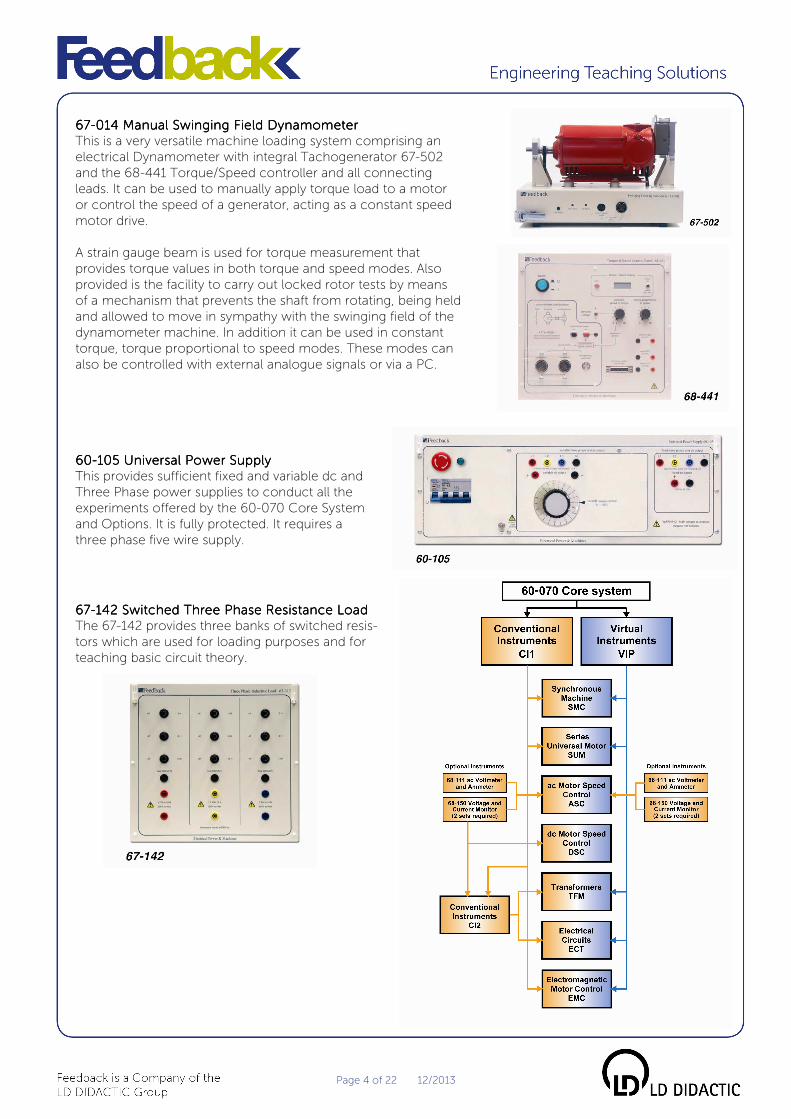
67676767----014 Manual Swinging Field D014 Manual Swinging Field D014 Manual Swinging Field D014 Manual Swinging Field Dyyyynamometernamometernamometernamometer
This is a very versatile machine loading system comprising an
electrical Dynamometer with integral Tachogenerator 67-502
and the 68-441 Torque/Speed controller and all connecting
leads. It can be used to manually apply torque load to a motor
or control the speed of a generator, acting as a constant speed
motor drive.
A strain gauge beam is used for torque measurement that
provides torque values in both torque and speed modes. Also
provided is the facility to carry out locked rotor tests by means
of a mechanism that prevents the shaft from rotating, being held
and allowed to move in sympathy with the swinging field of the
dynamometer machine. In addition it can be used in constant
torque, torque proportional to speed modes. These modes can
also be controlled with external analogue signals or via a PC.
60606060----105 Universal Power Supply105 Universal Power Supply105 Universal Power Supply105 Universal Power Supply
This provides sufficient fixed and variable dc and
Three Phase power supplies to conduct all the
experiments offered by the 60-070 Core System
and Options. It is fully protected. It requires a
three phase five wire supply.
66667777----142 Switched Three Phase142 Switched Three Phase142 Switched Three Phase142 Switched Three Phase Resistance LoadResistance LoadResistance LoadResistance Load
The 67-142 provides three banks of switched resis-
tors which are used for loading purposes and for
teaching basic circuit theory.

Page 5 of 22 12/2013
Core System additional machinesCore System additional machinesCore System additional machinesCore System additional machines
Synchronous Machine 60-070-SMC Three Phase Synchronous Machine & Three Phase Synchronous Machine & Three Phase Synchronous Machine & Three Phase Synchronous Machine &
Synchronising Module 60Synchronising Module 60Synchronising Module 60Synchronising Module 60----070070070070----SMCSMCSMCSMC
The Three Phase Synchronous Machine
can be used as a Motor or a Generator.
Starting requirements, synchronisation,
load and no-load characteristics and its
use as a synchronous capacitor are
some of the topics covered. In addition
the Synchronising Module shows how
the Three Phase generator can be
synchronised to the existing power supply. The versatility of the 60-070 allows sophisticated experiments
to be performed, such as, running the machine up to synchronous speed, synchronising as a generator,
changing to synchronous mode to a motor and studying the characteristics and pull-out torque.
Features • Lamps dark or lamps bright configuration
possible
• Synchronising switch included
• Star or delta winding configuration possible
• High degree of mechanical and electrical
protection
Curriculum Coverage • Open circuit test
• Short circuit test
• Effect of speed variation on output voltage
and frequency
• Synchronisation procedure
• Operation of a synchronous machine
• Voltage regulation of a synchronous machine
• Variable reactor V curves
Series Universal Motor 60-070-SUM
The Series Universal Motor is a simple, versatile and very
widely used device which can operate using a d.c. supply
or a single phase ac supply. Comparison is made between
the operation using the different supplies and the need for
a compensation winding is shown. All electrical machines
available in the 60-070 series are fitted with fully shrouded
electrical connectors, shaft guards; alignment pins and
quick fasten and release mechanical catches to retain
coupled machines.
Features • Mimic diagram of motor windings
• Realistic industrial frame size
• Electrical and mechanical protection
Curriculum Coverage • Motor characteristics with dc supply
• Speed versus torque
• Power versus torque
• Efficiency versus torque
• Motor characteristics with ac supply
• Speed versus torque
• Power versus torque
• Efficiency versus torque
• Control of shaft direction of rotation
• Compensation winding
Page 6 of 22 12/2013
Core System additional equipmentCore System additional equipmentCore System additional equipmentCore System additional equipment
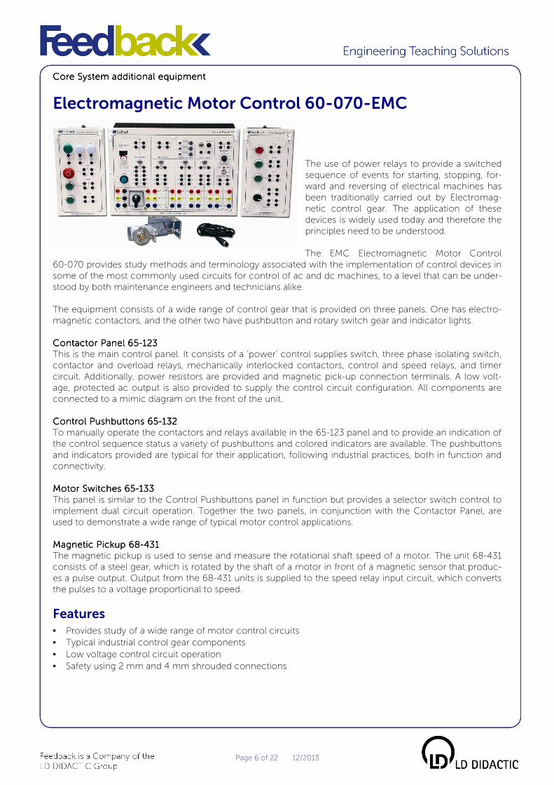
Electromagnetic Motor Control 60-070-EMC
The use of power relays to provide a switched
sequence of events for starting, stopping, for-
ward and reversing of electrical machines has
been traditionally carried out by Electromag-
netic control gear. The application of these
devices is widely used today and therefore the
principles need to be understood.
The EMC Electromagnetic Motor Control
60-070 provides study methods and terminology associated with the implementation of control devices in
some of the most commonly used circuits for control of ac and dc machines, to a level that can be under-
stood by both maintenance engineers and technicians alike.
The equipment consists of a wide range of control gear that is provided on three panels. One has electro-
magnetic contactors, and the other two have pushbutton and rotary switch gear and indicator lights.
Contactor Panel 65Contactor Panel 65Contactor Panel 65Contactor Panel 65----123123123123
This is the main control panel. It consists of a ‘power’ control supplies switch, three phase isolating switch,
contactor and overload relays, mechanically interlocked contactors, control and speed relays, and timer
circuit. Additionally, power resistors are provided and magnetic pick-up connection terminals. A low volt-
age, protected ac output is also provided to supply the control circuit configuration. All components are
connected to a mimic diagram on the front of the unit.
Control Pushbuttons 65Control Pushbuttons 65Control Pushbuttons 65Control Pushbuttons 65----132132132132
To manually operate the contactors and relays available in the 65-123 panel and to provide an indication of
the control sequence status a variety of pushbuttons and colored indicators are available. The pushbuttons
and indicators provided are typical for their application, following industrial practices, both in function and
connectivity.
Motor Switches 65Motor Switches 65Motor Switches 65Motor Switches 65----133133133133
This panel is similar to the Control Pushbuttons panel in function but provides a selector switch control to
implement dual circuit operation. Together the two panels, in conjunction with the Contactor Panel, are
used to demonstrate a wide range of typical motor control applications.
Magnetic Pickup 68Magnetic Pickup 68Magnetic Pickup 68Magnetic Pickup 68----431431431431
The magnetic pickup is used to sense and measure the rotational shaft speed of a motor. The unit 68-431
consists of a steel gear, which is rotated by the shaft of a motor in front of a magnetic sensor that produc-
es a pulse output. Output from the 68-431 units is supplied to the speed relay input circuit, which converts
the pulses to a voltage proportional to speed.
Features • Provides study of a wide range of motor control circuits
• Typical industrial control gear components
• Low voltage control circuit operation
• Safety using 2 mm and 4 mm shrouded connections
Page 7 of 22 12/2013
Curriculum Coverage • DOL starter, electromagnetic, locally controlledDOL starter, electromagnetic, locally controlledDOL starter, electromagnetic, locally controlledDOL starter, electromagnetic, locally controlled
• Two wire control
• Three wire control
• Local and Remote control
• DOL starter, starting/inching/joggingDOL starter, starting/inching/joggingDOL starter, starting/inching/joggingDOL starter, starting/inching/jogging
• Star/Delta starterStar/Delta starterStar/Delta starterStar/Delta starter
• Timer control of start to run
• Shaft speed switching
• Primary impedance staPrimary impedance staPrimary impedance staPrimary impedance starterrterrterrter
• DOL starter: Forward/Reverse operationDOL starter: Forward/Reverse operationDOL starter: Forward/Reverse operationDOL starter: Forward/Reverse operation
• DOL starter with dc injection brakingDOL starter with dc injection brakingDOL starter with dc injection brakingDOL starter with dc injection braking
• Timer control
• Speed relay control
• DOL starter with plugDOL starter with plugDOL starter with plugDOL starter with plug----brakingbrakingbrakingbraking
• Timer control
• Speed relay control
• d.d.d.d.cccc.... motor startermotor startermotor startermotor starter
• Operation with Timing relay
• Operation with speed relay
• DyDyDyDynamic braking of a dnamic braking of a dnamic braking of a dnamic braking of a d....cccc.... MotorMotorMotorMotor
• without added inertia
• with added inertia
• Introduction to switchgearIntroduction to switchgearIntroduction to switchgearIntroduction to switchgear
• Switching devices
• Electromagnetic switches
• Sensing relays
• Overload protection of motors
• a.c. contactor
• a.c. switch utilisation
• Switchgear symbols
• Motor configMotor configMotor configMotor configurationsurationsurationsurations
• Three-phase Induction Motor - Star Connection
• Three-phase Induction Motor - Delta Connection
• d.c. Compound-wound Motor - Shunt Connection
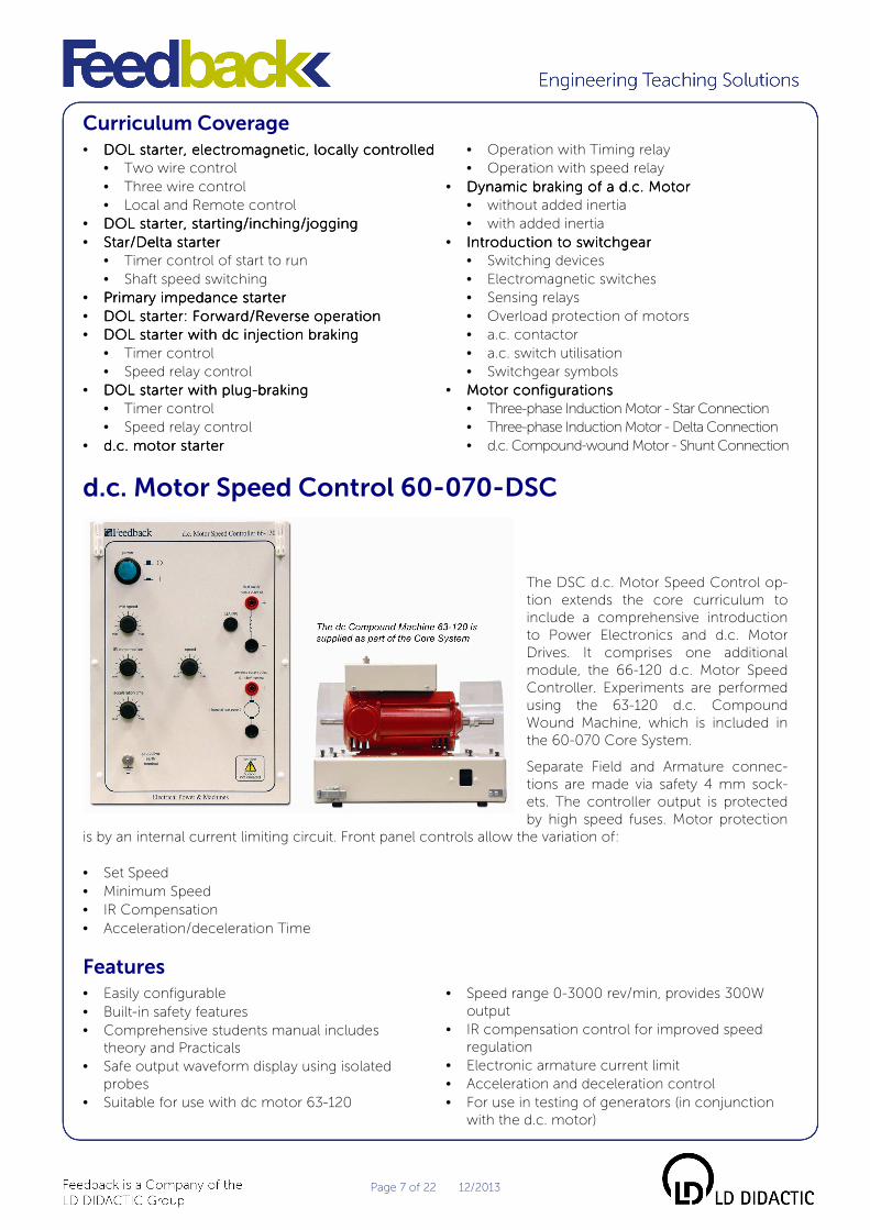
d.c. Motor Speed Control 60-070-DSC
The DSC d.c. Motor Speed Control op-
tion extends the core curriculum to
include a comprehensive introduction
to Power Electronics and d.c. Motor
Drives. It comprises one additional
module, the 66-120 d.c. Motor Speed
Controller. Experiments are performed
using the 63-120 d.c. Compound
Wound Machine, which is included in
the 60-070 Core System.
Separate Field and Armature connec-
tions are made via safety 4 mm sock-
ets. The controller output is protected
by high speed fuses. Motor protection
is by an internal current limiting circuit. Front panel controls allow the variation of:
• Set Speed
• Minimum Speed
• IR Compensation
• Acceleration/deceleration Time
Features • Easily configurable
• Built-in safety features
• Comprehensive students manual includes
theory and Practicals
• Safe output waveform display using isolated
probes
• Suitable for use with dc motor 63-120
• Speed range 0-3000 rev/min, provides 300W
output
• IR compensation control for improved speed
regulation
• Electronic armature current limit
• Acceleration and deceleration control
• For use in testing of generators (in conjunction
with the d.c. motor)

Page 8 of 22 12/2013
Curriculum Coverage • Thyristor dc motor control principles
• Motor voltage and current waveforms
• Speed regulation with and without
phase angle control
• Phase angle versus motor speed
• Effect of feedback voltage on speed regulation
• Current limit control
• Torque/speed performance
Optional Instruments In order to perform all the experiments in the manual for the above product the following instruments are
required (unless 60-070-VIP is already available in the lab).
Voltage and Current MonitVoltage and Current MonitVoltage and Current MonitVoltage and Current Monitor 68or 68or 68or 68----150 (2 sets r150 (2 sets r150 (2 sets r150 (2 sets reeeequired)quired)quired)quired)
• For use where isolated voltage and current waveform
measurements are required
• Precision four terminal shunt current monitor
• Shunt output isolated via voltage probe
• Probes output connects directly to a scope for safe monitoring
• Current monitor output 100 m V/A
• Isolated voltage probe input 1000 V d.c. or 700 V a.c. rms
• Switched attenuation 1/200 and 1/20 d.c. to 15 MHz bandwidth
• Battery powered or external 6 V d.c. power adapter
• Fully shrouded 4 mm connections with BNC to scope
a.c. Motor Speed Control 60-070-ASC
The ASC ac Motor Speed Control option
introduces the concepts of speed control
of ac motors using a variable frequency
drive. It comprises one additional module,
the 66-110 Variable Frequency Drive.
Experiments are performed using the
64-501 Three Phase Squirrel Cage Induc-
tion Motor which is included in the 60-070
Core System.
Connections to the Motor are made using
safety 4mm sockets and all outputs are
fully overload protected.
Front panel controls allow the variation of:
• Set Speed
• Minimum Frequency
• Voltage Boost
• Acceleration/deceleration Time

Page 9 of 22 12/2013
Features • Easily configurable
• Built-in safety features
• Comprehensive students manual includes
theory and Practicals
• Safe output waveform display using isolated
probes
• Suitable for use with Induction Motor 64-501
• Basic control functions for:Basic control functions for:Basic control functions for:Basic control functions for:
• Max and min speed settings
• Acceleration and deceleration times
• Torque boost
• Variable frequency control
• Protection is provided for over-current and over-
voltage
Curriculum Coverage • Basic Theory
• Control Functions
• Inverter Voltage Waveforms
• Carrier Frequency
• Inverter Current Waveforms
• Frequency, Speed, Current and Motor Voltage
• Torque/Speed test at various frequency settings
• Voltage Boost
• Voltage/Frequency (V/F) characteristics
Optional Instruments
In order to perform all the experiments in the manual for the above product, 2 sets of Voltage and Current
Probes (as described previously) and the following instrument are required:
aaaa....cccc.... Voltmeter and Ammeter 68Voltmeter and Ammeter 68Voltmeter and Ammeter 68Voltmeter and Ammeter 68----111111111111
• A rectifier voltmeter and moving iron ammeter
• Suited to the measurement of variable
frequency drive and a.c. supplies
• Rectifier voltmeter range 0 -250 V and 0 – 500 V a.c.
• Moving iron ammeter range 0 – 3 A, fuse protected
• Meters are DIN standard 96 x 96 mm
• Safety earth connection provided
Individual Modules
Universal Power Supply 60-105 • Comprehensive Power Supply
• Circuit breaker protection
• 3-phase: nominally 0 – 400 V a.c. line at 4 A
• 3 x Single Phase: each nominally 0 – 230 V a.c. line to neutral
at 4 A d.c. nominally 0 – 270 V at 6 A
• Three Phase 400 V line, 230 V Single Phase, fixed d.c. 220 V 10 A
• Single Phase power distribution
• Safety earth connection provided

Page 10 of 22 12/2013
Variable a.c./d.c. Supply 5 A 60-121 • A variable a.c./d.c. supply using a variable transformer
and a silicon bridge rectifier circuit
• Provides up to 240 V a.c. or 220 V d.c. at up to 5 A
• Equipped with ON/OFF switch, variable voltage control, a.c./d.c. selector and
current overload protection
• Nominal voltage 220/240 V a.c., 50/60 Hz 5 A
• Safety earth connection provided
Three Phase Supply 60-132 The 60-132 can be configured to provide the desired single phase or
three phase power to the 70-220
• Overcurrent power switch
• 600 VA output on single and 3-phase at 200 VA per phase
• Star or delta 3-phase configuration
• 2 x 100 V windings per phase
• Input requirement: 380 – 415 V 5 wire. 3 x line, neutral and earth
Single Phase Transformer 61-106 • Multi-windings for series and parallel connection
• 400 V, 230 V and 2 x 115 V windings
• Power rating 100 VA
• Mimic panel of transformer windings
• Frame or bench mounting
• Safety earth connection provided
Three Phase Transformer 61-107 • Primaries for 380/415 V a.c. Star or Delta connection
• 2 x 115 V, 0.43 A secondaries per phase
• Power rating 300 VA
• Connects via 4 mm colour coded shrouded safety sockets on mimic panel
• Frame mounting
• Safety earth connection provided
Three Phase Earth Leakage Breaker 60-140-1 • For use in systems where earth leakage breakers are not provided as part of the
electrical installation but overcurrent protection has been installed
• Suitable for connection to 3-phase, five wire systems
• Provides a termination point for mains power on frame systems
• 4 pole, 30 mA trip, earth leakage breaker
• Three phase power ‘on’ indicators
• Single phase outlets on front and rear
• Safety earth terminals
• Input 380/415 V 3-phase 50/60 Hz with neutral and earth connections
• User connection terminal block provided internally
• Output 220/240 V single phase from IEC shuttered sockets, fuse protected at 10 A
• 3-phase on rear panel connector for use with frames supplies 60-105 and 60-125
• Provides additional protection against the hazard of electric shock
Page 11 of 22 12/2013
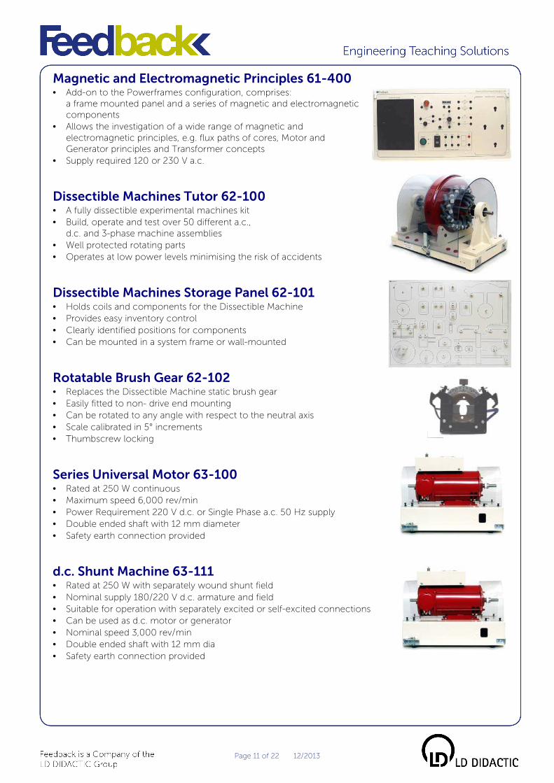
Magnetic and Electromagnetic Principles 61-400 • Add-on to the Powerframes configuration, comprises:
a frame mounted panel and a series of magnetic and electromagnetic
components
• Allows the investigation of a wide range of magnetic and
electromagnetic principles, e.g. flux paths of cores, Motor and
Generator principles and Transformer concepts
• Supply required 120 or 230 V a.c.
Dissectible Machines Tutor 62-100 • A fully dissectible experimental machines kit
• Build, operate and test over 50 different a.c.,
d.c. and 3-phase machine assemblies
• Well protected rotating parts
• Operates at low power levels minimising the risk of accidents
Dissectible Machines Storage Panel 62-101 • Holds coils and components for the Dissectible Machine
• Provides easy inventory control
• Clearly identified positions for components
• Can be mounted in a system frame or wall-mounted
Rotatable Brush Gear 62-102 • Replaces the Dissectible Machine static brush gear
• Easily fitted to non- drive end mounting
• Can be rotated to any angle with respect to the neutral axis
• Scale calibrated in 5° increments
• Thumbscrew locking
Series Universal Motor 63-100 • Rated at 250 W continuous
• Maximum speed 6,000 rev/min
• Power Requirement 220 V d.c. or Single Phase a.c. 50 Hz supply
• Double ended shaft with 12 mm diameter
• Safety earth connection provided
d.c. Shunt Machine 63-111 • Rated at 250 W with separately wound shunt field
• Nominal supply 180/220 V d.c. armature and field
• Suitable for operation with separately excited or self-excited connections
• Can be used as d.c. motor or generator
• Nominal speed 3,000 rev/min
• Double ended shaft with 12 mm dia
• Safety earth connection provided

Page 12 of 22 12/2013
d.c. Compound Wound Machine 63-120 • Rated at 250 W continuous
• Nominal speed 2,000 rev/min
• Maximum speed 6,000 rev/min
• Power requirement 220 V d.c.
• Operates as a d.c. series, shunt and compound motor or generator
• Double ended shaft with 12 mm dia
• Safety earth connection provided
d.c. Variable Speed Drive 63-501 Comprises a 250 W horsepower d.c. motor mounted on a base unit
compatible with all the machines in the Powerframes range. Contained in the
base of the motor is a thyristor-controlled power supply which provides a
shaft speed range from zero to 4250 rev/min, with all controls and fuses on
the front panel. It has constant current overload limiting electronic control to
give good regulation, and a fool-proof soft-start to ensure safe run-up to full
speed. A built-in tachogenerator with integral metering is also provided for
indication of shaft speed. Drive shaft diameter 12 mm.
Capacitor Start Single Phase Induction Run - 64-110 • Rated 250 W
• Rotates at up to 2850 rev/min at 50 Hz
• Power requirement 220 V Single Phase a.c.
• 12 mm shaft diameter
• Double ended shaft
• Safety earth connection provided
Three Phase Induction Motor - Squirrel Cage, Dual Voltage 64-501 • Dual voltage machine, 380/415 V, Star, 220/240 V Delta
• Rated at 250 W
• Rotates at up to 2980 rev/min at 50 Hz
• Power requirement 380/415 V, 50 Hz, Three Phase a.c. or 220/240 V delta
• 12 mm shaft diameter
• Double ended shaft
• Safety earth connection provided
Three Phase Synchronous Motor/ Generator - Wound Rotor 64-510 • Can be used as a motor or generator
• Rated at 415/240 V 200 W
• Synchronous speed 3,000 rev/min@50 Hz
• Power Requirement 380/415 V Three Phase a.c. star or 220/240 V delta
• Nominal rotor supply 100 V d.c.
• 12 mm shaft diameter
• Double ended shaft
• Safety earth connection provided

Page 13 of 22 12/2013
Contactor Panel 65-123 • 3-phase isolating switch, fused at 5 A
• Power control pushbutton connecting 24 V a.c.
to contactors, relay and speed control circuit
• Contactor with thermal overload relay
• 2 contactors mechanically interlocked
• Control relay fitted with pneumatic timer
• Speed relay with adjustable speed threshold to 4,000 rev/min
• Three 50 ohm 100 W power resistors
• Supply requirements 230 V or 120 V a.c. 50/60 Hz
• Safety earth connection provided
Control Switches 65-130 • Heavy duty power switches used in measurement and electrical circuit switching
• Multipoint metering
• Component selection
• Switches are:- 1 x 3 way, 3 x 1 way, 1 x 4 way
• Switch ratings 240 V a.c. 10 A
• Used with 62-100 Dissectible Machine
• Safety earth connection provided
Control Pushbuttons 65-132 • Three pushbuttons with contacts, 1 N/O and 1 N/C
One button mushroom head type, two flush head type
• Three indicator lamps, two white, one green – 24 V/0.12 A
• For use with Contactor Panel 65-123
• Safety earth connection provided
Motor Switches 65-133 • Three pushbuttons with contacts, 1 N/O and 1 N/C
One button mushroom head type, two flush head type
• Three position selector switch, 1/OFF/2. 1 and 2 positions
have 1 N/O and 1 N/C contacts
• For use with Contactor Panel 65-123
• Safety earth connection provided
Variable Frequency Drive 66-110
• A Three Phase variable frequency output voltage to vary
the speed of the Three Phase Induction Motor 64-501
• Basic control functions are provided for:Basic control functions are provided for:Basic control functions are provided for:Basic control functions are provided for:
• Maximum & minimum speed settings.
• Acceleration & deceleration times
• Torque boost
• Variable Frequency Control
• Protection is provided for overcurrent & overvoltage. Output power 0.4 kW
• Supply: 180-250 V a.c. at 5 A 50/60 Hz single phase
• Motor earth terminal

Page 14 of 22 12/2013
d.c. Motor Speed Controller 66-120 • Suitable for use with 63-110 and 63-120 d.c. motors
• Speed range 0 to 3,000 rev/min. Provides 300 W output
• Adjustable IR compensation control for improved speed regulation
• Used as a drive when testing generators
• Acceleration & deceleration control
• Supply 200-240 V a.c. at 5 A 50/60 Hz
• Motor earth terminal
Variable Resistance 200 ohms 3 A 67-113 • High power variable resistance element for use
where short-term dissipation is required in applications such as:
� Generator loading
� Motor starting
� Motor speed control applications
• Fuse protected at 3.15 A
• Safety earth connection provided
Switched 3-phase Resistance Load 230/380V 67-142 • Three resistor switched load banks
• Seven resistor values per bank
• 547 – 3770 ohms per bank. 100 W per bank
• Total Three Phase loading for Star@400 V or Delta@230 V, 300 watts
• Fuse protected at 0.5 A
• Safety earth connection provided
Resistor/Capacitor Unit 67-190 • Low power resistive/reactive component unit
• Resistive elements 3 x 68 ohms
• Capacitive elements: 2 µF, 4 µF and 8 µF
• Nominal ratings:
Resistance 50 W each
Capacitors 400 V (63 V for 10 mF)
• Fuse protected at 3.15 A
• Specifically for use with 62-100 Dissectible Machine components
• Safety earth connection provided
Switched Capacitive Load 50µF 67-201 • Three capacitive switched load
• Seven capacitive values
• 10 – 50 µF
• 976 VAR@250 V a.c., 50 Hz
• Fuse protected at 4 A
• Safety earth connection provided

Page 15 of 22 12/2013
Switched 3-phase Capacitive Load 230/380 V 67-212 • Three capacitive switched load banks
• Seven capacitive values per bank
• 1 – 7 µF per bank
• 116 VAR@230 V a.c., 50 Hz per bank
• Total Three Phase loading for star @400 V or Delta@230 V, 348 VAR
• Fuse protected at 0.8 A per bank
• Safety earth connection provided
Inductive Load 700 mH 67-300 • A load consisting of a variable 700 mH inductive component
• Variation is obtained by means of an infinitely variable sliding iron core
• Fused at 2 A, 250 V max
• Rated at 2 A 220 V 50 Hz
• Safety earth connection provided
Switched 3-phase Inductive Load 230/380 V 67-312 • Three inductive switched load banks
• Seven inductive values per bank
• 1.7 H – 12 H per bank
• 100 VAR@230 V, 50 Hz per bank
• Total Three Phase loading for Star@400 V or Delta@230 V, 300 VAR
• Fuse protected at 0.5 A per bank
• Safety earth connection provided
Inertia Wheel 67-450 • Used with the Electrical Machine
• Fits onto non drive end of shaft to increase existing rotor inertia on synchronous
generators and d.c. machines
• Provides additional inertia load on control systems to investigate their behaviour
• Mass 1.5 kg
• Fits 12 mm shaft diameter
Friction (Prony) Brake 67-470 • Fits directly onto the shaft of Feedback machines
• Provides direct loading with integral measurement of the torque output
of various motor assemblies
• Indicates torque output in either direction
• Fits 12 mm, 1/2 and 5/8 inch shafts
• Torque range ±2 Nm
Manual Swinging Field Dynamometer 67-502 • Movable frame and field assembly
• Higher accuracy torque output
• Strain gauge gives an output proportional to
load torque in both torque and speed modes
• Lock rotor test facility for stall torque measurements
• Powered directly from 68-441 Control Panel
• Permanently mounted d.c. Tachogenerator
• Speed: ±5000 rpm maximum
• Torque: ±3 Nm maximum

Page 16 of 22 12/2013
Electronic Single and Three Phase Measurements 68-100 • Measures voltage, current, power, power factor, watts, KVA, KVAR
and KWH etc. on 3 to 4 wire, balanced/unbalanced 3-phase systems
• Rated at 750 V a.c. at 5 A per phase
• Supply 230 or 120 V a.c. 50/60 Hz
• Digital readout of values
• Programmable setting
• Simple connections by 4 mm shrouded connecting leads
d.c. Voltmeter and Ammeter 68-110 • Moving coil d.c. voltmeter
• Voltmeter ranges 0 - 50, 0 - 250, and 0 - 500 V d.c.
• Ammeter range 0 - 1 A, 0 - 5A & 0 - 10 A d.c.
• Ammeter is fuse protected
• Meters are to DIN standard 96 x 96 mm
• Safety earth connection provided
a.c. Voltmeter and Ammeter 68-111 • A rectifier voltmeter and moving iron ammeter
• Suited to the measurement of variable frequency drives and a.c. supplies
• Rectifier voltmeter range 0 – 250 V and 0 – 500 V a.c.
• Moving iron ammeter range 0 - 3 A
• Meters are DIN standard 96 x 96 mm
• Safety earth connection provided
d.c. Milli-ammeter, Centre Zero 68-113 • Ideal instrument for use in:
� Electrical circuit investigations
� Motor/generator set-ups
• Provides direct indication of polarity and polarity reversal
• Ranges:- ±1 mA, ±1 A and ±5 A
• Meters are to DIN standard 96 x 96 mm
• Safety earth connection provided
Moving Iron Voltmeter and Ammeter 68-114 • For use on a.c. circuits
• Voltage ranges up to 500 V
• Current range to 2 A
• Ammeter is fuse protected
• Meters are to DIN standard 96 x 96 mm
• Safety earth connection provided
Page 17 of 22 12/2013
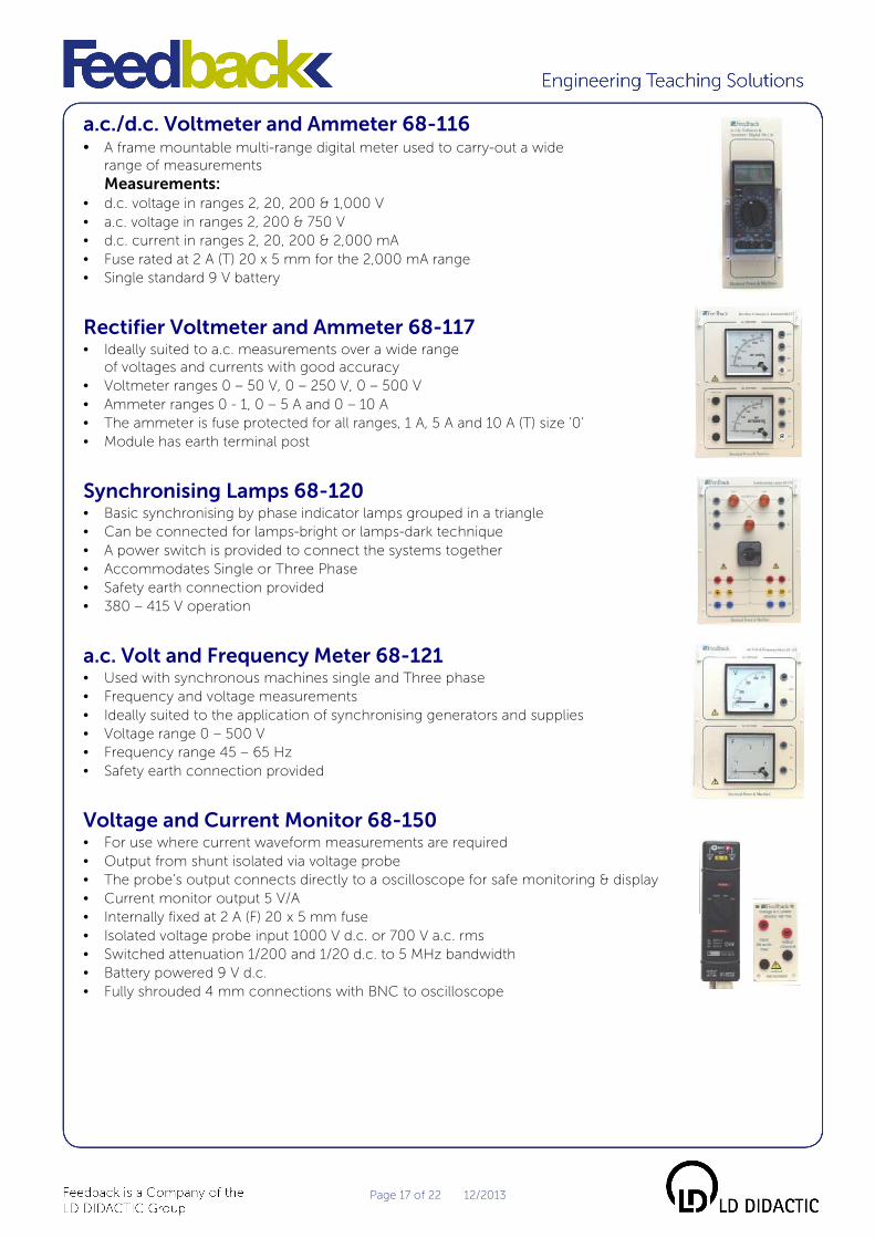
a.c./d.c. Voltmeter and Ammeter 68-116 • A frame mountable multi-range digital meter used to carry-out a wide
range of measurements Measurements:
• d.c. voltage in ranges 2, 20, 200 & 1,000 V
• a.c. voltage in ranges 2, 200 & 750 V
• d.c. current in ranges 2, 20, 200 & 2,000 mA
• Fuse rated at 2 A (T) 20 x 5 mm for the 2,000 mA range
• Single standard 9 V battery
Rectifier Voltmeter and Ammeter 68-117 • Ideally suited to a.c. measurements over a wide range
of voltages and currents with good accuracy
• Voltmeter ranges 0 – 50 V, 0 – 250 V, 0 – 500 V
• Ammeter ranges 0 - 1, 0 – 5 A and 0 – 10 A
• The ammeter is fuse protected for all ranges, 1 A, 5 A and 10 A (T) size ‘0’
• Module has earth terminal post
Synchronising Lamps 68-120 • Basic synchronising by phase indicator lamps grouped in a triangle
• Can be connected for lamps-bright or lamps-dark technique
• A power switch is provided to connect the systems together
• Accommodates Single or Three Phase
• Safety earth connection provided
• 380 – 415 V operation
a.c. Volt and Frequency Meter 68-121 • Used with synchronous machines single and Three phase
• Frequency and voltage measurements
• Ideally suited to the application of synchronising generators and supplies
• Voltage range 0 – 500 V
• Frequency range 45 – 65 Hz
• Safety earth connection provided
Voltage and Current Monitor 68-150 • For use where current waveform measurements are required
• Output from shunt isolated via voltage probe
• The probe’s output connects directly to a oscilloscope for safe monitoring & display
• Current monitor output 5 V/A
• Internally fixed at 2 A (F) 20 x 5 mm fuse
• Isolated voltage probe input 1000 V d.c. or 700 V a.c. rms
• Switched attenuation 1/200 and 1/20 d.c. to 5 MHz bandwidth
• Battery powered 9 V d.c.
• Fully shrouded 4 mm connections with BNC to oscilloscope

Page 18 of 22 12/2013
Differential Voltage Probe 68-151 • Differential isolation probe
• Probes output connects directly to an oscilloscope
allowing safe conditions for monitoring & display
• Requires 4 x 5 V batteries AA size
• Switched attenuation 1/200 & 1/20 d.c. to 15 MHz bandwidth
• Shrouded 4mm plugs for circuit connection with BNC connector to oscilloscope
• Maximum input 1,000 V d.c. 700 V RMS
a.c./d.c. Electronic Wattmeter 68-200 • Selectable voltage and current ranges up to 1,000 V 10 A
• Measurement up to 10 kW
• Ideally suited for use at frequencies of 20 Hz to 20 kHz
• Multi-scaled analogue meter displays measured power value
• Meter to DIN standard 96 x 96 mm
• Supply requirement 230 or 120 V a.c. 50/60 Hz
• Fuse protected current range 10 A(T). Size 11/4 x 1/4 inch
• Overload indicators
a.c./d.c. Electrodynamic Wattmeter 68-204 • Selectable voltage and current ranges up to 500 V 0.5 A/1A
• Measurement up to 500 W
• Ideally suited for use at mains supply frequencies of 50/60 Hz and d.c.
• Multi-scaled analogue meter displays measured power value
• Meters are to DIN standard 96 x 96 mm
• Fuse protected current ranges 0.5 A (T). Size 20 x 5 mm.
• Safety earth connection provided.
d.c. Tachogenerator 68-430 • Fits to base of 63 and 64 series electrical machines
• Provides d.c. output proportional to shaft speed
• Output 2 V d.c./1,000 rev/min on 5 pin DIN socket
Magnetic Pick-up 68-431 • Provides a single pulse train suitable for speed measurement
• Attaches to motor base and shaft on 63 and 64 series electrical machines
• Output 64 pulses/rev
• Connects via 5 pin DIN 180° connector
• For use with Contactor Panel 65-123
Torque and Speed Control 68-441 • Used with machine Dynamometer 67-502
• Provides manual control of torque and speed
• Constant torque and torque proportional with speed controls
• Digital display for speed or torque
• Can be used with 68-500 virtual instrumentation panel
• Speed range ±5,000 rev/min. Torque range ±3 Nm
• Supply 220 – 250 V a.c. 50 Hz

Page 19 of 22 12/2013
Hand-held Digital Optical/Contact Tachometer 68-470 • Versatile measuring of shaft speed
• Non-contact by photo sensing
• Direct shaft contact through conical rubber drive
• Measurement range 99,999 rev/min non-contact, 20,000 rev/min contact
• Battery powered
Multi-channel I/O Unit 68-500 with USB interface and software • Used with software to evaluate the behaviour of electrical systems
• Software provides on-screen instrumentation of:
� a.c. and d.c. Voltmeters and ammeters
� d.c. Wattmeter
� Single and Three phase Wattmeter
� Phase Meter
• VA Meter
• Vector display
• Six isolated channels
• 3 voltage & 3 isolated current channels
• Supply 230 or 120 V a.c. 50/60 Hz
Shaft Couplings and Keys Couples 62, 63 & 64 series motors to motor/generator for multi-machine experiments.
68-702 1/2 inch to 12 mm
68-703 12 mm shaft to 12 mm shaft
68-704 12 mm to 5/8 inch
68-705 1/2 inch to 5/8 inch
Standard set of Patch leads 68-800 For interconnections between panels and bench mounted equipment. Leads are
fitted with 4 mm stackable shrouded safety connectors made from double
insulated cable. 33 lead of various colours & lengths.
5 pin DIN-DIN lead 68-810 1 M long, this lead is used to connect between the tachogenerator unit 68-430 or
Magnetic Pick-up 68-431 to the appropriate control panel.
Lead Storage 91-245 The storage rack is designed to take the three lengths of patch lead used in the 68-800
lead set. Frame or wall mounting.

Page 20 of 22 12/2013
Dissectible Machines Storage System 90-100 The storage system holds all coils, leads and components for
the Complete Dissectible Machines System 62-005. It has
clearly identified positions for components for easy inventory
control, with two extra bins for further storage.
System Frame 91-200 • Easy “lift-in/out” panel removal.
• Maximises bench space.
• Provides clear view of multi-panel experiments.
• Made from non-conductive fibre-glass reinforced resin
loaded material.
Storage Bi 91-240 • Holds items associated with the Powerframes system.
• Can be used in either landscape or portrait format.
Oscilloscope/Computer Housing 91-210-1 • Suitable for conventional desktop computer and
oscilloscope cases.
• Can be positioned anywhere in the A4 area of the frame.
Size: W: 380 mm, H: 250 mm, D: 500 mm.

Page 21 of 22 12/2013
Power Electronic Modules
Firing and Bridge circuits 70-220 The Firing & Bridges panel contains the diode and thyristor devices required
for Single and Three Phase uncontrolled and controlled rectification
together with the firing circuits for the thyristors. The panel also contains
the power supplies required for operating the firing circuits, and isolated
voltage and current probes for use in waveform observation and control
purposes.
The unit contains
• Front panel mimic diagram of circuits and devices.
• Six power diodes and six thyristors that can be connected into various circuit
configurations with 4 mm plug leads.
• Three individual firing pulse circuits that produce firing pulses for
Single & Three Phase circuits; 1, 2, 4 & 6 pulse options.
• Firing pulse selector, 0 - 180° or 180° and 360° or overlap firing pulses can be selected.
• Reference voltage output control, 0 – 10 V.
• Supply requirements - 120 or 240 V a.c. and Three Phase output from the power supply unit 60-132.
Three Phase Supply 60-132 The 60-132 can be configured to provide the desired single phase
or three phase power to the 70-220.
• Overcurrent power switch.
• 600 VA output on single and 3-phase at 200 VA per phase.
• Star or delta 3-phase configuration.
• 2 x 100 V windings per phase.
• Input requirement: 380 – 415 V 5 wire. 3 x line, neutral and earth.
SCR and Diodes 70-100 The unit extends the use of the Firing and Bridge circuits panel by providing a second set
of power diodes and thyristors. From these, a thyristor converter can be interconnected
to form, with the Bridges panel, a dual converter, either Single or 3-Phase, to control
power to a passive or active load such as a d.c. motor. The front panel mimic shows six
diode and six thyristors together with voltage and current probes.
Supply requirements
• Three Phase five wire connection at the rear panel, L1, L2, L3,
neutral and earth supplied via the Bridges panel from the Three Phase Supply 60-132.
• Operating voltage nominally 170 V 50/60 Hz Three Phase.
Motor Control circuits 70-310 Designed to be used with Firing Circuits and Bridges panel, this unit provides
the control circuits for motor control and zero crossing burst fire study. A
mimic diagram depicts the available circuits for motor control. These can be
interconnected to perform different control options. A second circuit is shown
for burst fire control that is connected to the bridge circuits for study of a.c.
power control. Monitor sockets are provided at various points on the circuit for
a voltmeter or an oscilloscope to be used for measurement.
Burst Fire Circuit Controls
• Set power level
• Error amplifier gain
• Pulse interval time control

Page 22 of 22 12/2013
Motor Control Circuit Controls
• Reference voltage control
0 – 10 V, ±10 V or OFF by selector switch.
• Acceleration/deceleration time.
• Speed controller proportion gain.
• Speed controller Integral action time.
• Current controller proportional gain.
• Current controller Integral action time.
• Current limit variable control.
• Separate variable attenuator
•
Ordering Information 60-105 Universal Power Supply
60-121 Variable a.c./d.c. Supply 5 A
60-132 3-Phase Supply (Power Electronics)
61-106 Single Phase Transformer
61-107 Three Phase Transformer
61-140-1 Three Phase Earth Leakage Breaker
61-400 Electromagnetic and Magnetic Principles
62-100 Dissectible Machines Tutor
62-101 Dissectible Machines Storage Panel
62-102 Rotatable Brush Gear
63-100 Series Universal Motor
63-111 d.c. Shunt Machine
63-120 d.c. Compound Wound Machine
63-501 d.c. Variable Speed Drive
64-110 Capacitor Start Single Phase Induction Run
64-501 3-Phase Induction Motor -
Squirrel Cage, Dual Voltage
64-510 3-Phase Synchronous Motor/
Generator - Wound Rotor
65-123 Contactor Panel
65-130 Control Switches
65-132 Control Pushbuttons
65-133 Motor Switches
66-110 Variable Frequency Drive
66-120 d.c. Motor Speed Controller
67-113 Variable Resistance 200 W 3 A
67-142 Switched 3-phase Resistance Load 230/380 V
67-190 Resistor/Capacitor Unit
67-201 Switched Capacitive Load 50 µF
67-212 Switched 3-phase Capacitive Load 230/380 V
67-300 Inductive Load 700 mH
67-312 Switched 3-phase Inductive Load 230/380 V
67-450 Inertia Wheel
67-470 Friction (Prony) Brake
67-502 Manual Swinging Field Dynamometer
68-100 Electronic Single and Three Phase Measurements
68-110 d.c. Voltmeter and Ammeter
68-111 a.c. Voltmeter and Ammeter
68-113 d.c. Milli ammeter, Centre Zero
68-116 a.c./d.c. Voltmeter & Ammeter (Digital)
68-114 Moving Iron Voltmeter & Ammeter
68-117 Rectifier Voltmeter and Ammeter
68-120 Synchronising Lamps
68-121 a.c. Volt and Frequency Meter
68-150 Voltage and Current Monitor
68-151 Differential Voltage Probe
68-200 a.c./d.c. Electronic Wattmeter
68-204 a.c./d.c. Electrodynamic Wattmeter
68-430 d.c. Tachogenerator
68-431 Magnetic Pick-up
68-441 Torque and Speed Control Panel
68-470 Hand-held Digital Optical/Contact Tachometer
68-500 Multi-channel I/O Unit with I/O board and software
68-702 Shaft Coupling 1/2 inch to 12 mm
68-703 Shaft Coupling 12 mm to 12 mm and Key
68-704 Shaft Coupling 12 mm to 5/8 inch and Key
68-705 Shaft Coupling 1/2 inch to 5/8 inch and Key
68-800 Standard set of Patch leads
68-810 5 pin DIN-DIN lead
90-100 Dissectible Machines Storage System
91-200 System Frame
91-210-1 Oscilloscope/Computer Housing
91-240 Storage Bin
91-245 Lead Storage
70-100 SCR and Diodes
70-220 Firing and Bridge circuits
70-310 Motor Control circuits
60-070-CS Electrical machines Core System
60-070-SMC Synchronous machine
60-070-SUM Series Universal Motor
60-070-CI1 Conventional Instruments
60-070-VIP Virtual Instrumentation
60-070-TFM Transformers
60-070-ECT Electrical Circuits
60-070-EMC Electromagnetic Motor Control
60-070-DSC d.c. Motor Speed Control
60-070-ASC a.c. Motor Speed Control
60-070-CI2 Conventional Instruments
60-140-1 Three Phase Earth Leakage Breaker
Feedback InstrumentsFeedback InstrumentsFeedback InstrumentsFeedback Instruments
5 & 6 Warren Court
Park Road, Crowborough
East Sussex
TN6 2QX
United Kingdom
Tel: +44 1892 653322
Sales: [email protected]
Website: www.feedback-instruments.com
Feedback reserves the right to change these specifications without notice.
For further information on Feedback equipment please contact …