
ELECTRICAL OPTICAL S R H - Moog Inc.
32
Electrical Optical Slip Ring Handbook Document Number: 700-0096-00, Rev 20 Issue Date: 2017 May Focal Technologies Corporation A Moog Inc. Company 77 Frazee Avenue Dartmouth, Nova Scotia, Canada B3B 1Z4 Tel: (902) 468-2263 | www.moog.com/focal ELECTRICAL OPTICAL SLIP RING HANDBOOK Slip Ring Serial Number Installation Drawing
Transcript of ELECTRICAL OPTICAL S R H - Moog Inc.

Electrical Optical Slip Ring Handbook Document Number: 700-0096-00, Rev 20
Issue Date: 2017 May
Focal Technologies Corporation A Moog Inc. Company 77 Frazee Avenue Dartmouth, Nova Scotia, Canada B3B 1Z4 Tel: (902) 468-2263 | www.moog.com/focal
ELECTRICAL OPTICAL SLIP RING HANDBOOK
Slip Ring Serial Number Installation Drawing

Electrical Optical Slip Ring Handbook
Focal Technologies Corporation Page 2 of 32 A Moog Inc. Company Document Number: 700-0096-00, Rev 20
Revision Record
Rev. Page Modifications Date
11 2 Added a revision and revision date 2010 Jan 5
5 Models 139 and 161 deleted. Para 3, ambient temperature, added
6 Model 286 and 300 added. FRU Model list added. Section updated
8 Reference to Figure 4 removed (Figure 4 not relevant and was deleted)
13 Figure 4 was Figure 5
14 Figure 5 was Figure 6, Figure 6 was Figure 7
16 Type of torque arrester and reference to Figure 7 added. Added Fiber Optic cable handling instructions to Cable Handling section.
21 Purge section rewritten to reflect purging in hazardous areas
23 IS section added. Requirement for conduit seals on Ex units. Warranty implications of poured seals added. Warning on opening the enclosure added. Paragraph on flamepath dimensions added.
24 Added paragraph on fasteners for flameproof slip rings
25 Appendix added
- ‘EEx’ replaced with ‘Ex’
12
Added section numbers 2011 Feb 28
Section
3 30 °C was 40 °C
6 Added section
8 Changed Figure 7; added torque arm installation instructions
10 Added flushing of pressure compensator
12 Added “0334” to the hazardous area designation (0334 is Dekra’s notified body number) Ground Stud was ¼”.
13 Added the marking for the Model 180-X having intrinsically safe passes
15 Clarified the fastener material specification Added a section on removal of the COVER ASSEMBLY for the Model 176-X
17 Added section
13 Dekra was Kema
Section
12 was added to the certification
13 was added to the certification
14 Section 12 13
Gb added to the certification Gb added to the certification

Electrical Optical Slip Ring Handbook
Focal Technologies Corporation Page 3 of 32 A Moog Inc. Company Document Number: 700-0096-00, Rev 20
Revision Record cont.
15 Section 13
Remove the brackets around ib the slip ring label will be marked 0344 II 2 G Ex d ib IIB T5 Gb.
2012 Apr 16
16 Section 12
Added to 3rd / 4th paragraph:
Installation is to be in accordance with the requirements of the local authority having jurisdiction. Cable entries are to be properly sealed and the slip ring suitably grounded in accordance with local electrical codes. It is necessary that applicable installation rules be reviewed, understood and applied to ensure a safe installation.
The cable entry devices shall be of the appropriate certification and suitable for conditions of use per the installation rules. Unused openings shall be closed by certified blanking elements. If conduit is used, a sealing device with a suitable setting compound for the application shall be installed immediately at the entrance to the explosion-proof / flameproof enclosure.
2012 May 30
17 Section 4
Section 5
Section 12
Remove Models 145 & 214 and add Model 310
Remove Model 271
Replaced 2nd paragraph with Intertek, CSA and DEKRA information. Change to Conduit System paragraph for clarity.
2013 Apr 18
18 Cover
Section 15
Updated to new Focal Logo Added paragraph regarding battery life for the Model 923 Data Acquisition System.
2015 Aug 5
19 Section 12
Added direction to ensure that pigtails for slip rings with non-potted cable glands have a minimum length of 3m [10’]. Updated cover to reflect new branding layout. Added content for Model 295-X/159-X
2015 Dec 18
20 TOC
Section 6
Section 7
Section 12
Section 10
TOC updated to reflect actual section headings.
Updated to torque arm shipping information
Updated to highlight inspection for damage to the hose nipple prior to install and upon removal
Added paragraph regarding conditions of certification for safe use. CSA replaced with INTERTEK (ETL). CSA certificates reference removed. Paragraph order changed. 0344 II 2 G Ex db IIB T5 Gb was
0344II 2 G Ex d IIB T5 Gb. Ex db IIB T5 Gb was Ex d IIB T5 Gb. The Appendix has been merged with Section 10. A maintenance interval has been included for oil-filled slip rings.
2017 May 31

Electrical Optical Slip Ring Handbook
Focal Technologies Corporation Page 4 of 32 A Moog Inc. Company Document Number: 700-0096-00, Rev 20
1. INTRODUCTION................................................................................................. 7
2. THE INSTALLATION DRAWING ........................................................................ 7
3. ELECTRICAL SLIP RINGS ................................................................................. 7
4. FIBER OPTIC ROTARY JOINTS ........................................................................ 8
5. FLUID ROTARY UNIONS ................................................................................... 8
6. RECEIVING ........................................................................................................ 9
7. MOUNTING AND INSTALLATION .................................................................... 10
8. TORQUE ARM .................................................................................................. 17
9. CABLE HANDLING ........................................................................................... 19
10. FLUID FILLING ................................................................................................. 20
11. PURGING/PRESSURIZATION ......................................................................... 23
12. EXPLOSION-PROOF / FLAMEPROOF SLIP RINGS ....................................... 26
13. INTRINSIC SAFETY ......................................................................................... 29
14. ADDITIONS TO THE HANDBOOK ................................................................... 29
15. MAINTENANCE ................................................................................................ 29
16. PRESERVATION .............................................................................................. 31
17. RETURN ........................................................................................................... 32

Electrical Optical Slip Ring Handbook
Focal Technologies Corporation Page 5 of 32 A Moog Inc. Company Document Number: 700-0096-00, Rev 20
WARNING
Read the installation instructions before connecting the system to the power source.
AVERTISSEMENT
Lire les instructions d'installation avant de connecter le système à la source d’énergie.
ADVARSEL
Læs intallationsvejledning før tilslutning af strøm til systemet
WAARSCHUWING
Lees de installatie instructies voordat u het systeem aansluit op de voeding
ADVARSEL
Les installasjonsveiledning før nettspenning tilkobles system
VARNING
Läs installationanvisningarna innan tillkoppling till spänningskälla.
ACHTUNG
Die Installationsanweisungen vor dem Anschliessen des Stroms lesen.
ATTENZIONE
Leggere le istruzioni d’istallazione prima di collegare il sistema alla presa di corrente
AVISO
Ler as instruções de montagem antes de ligar o sistema à fonte de energia.
Electrical Optical Slip Ring Handbook
Focal Technologies Corporation Page 6 of 32 A Moog Inc. Company Document Number: 700-0096-00, Rev 20
WARNING
This warning symbol means danger / beware. You are in a situation that could cause bodily injury. Before you work on any equipment, be aware of the hazards involved with the electrical circuitry and be familiar with standard practices for preventing accidents.
AVERTISSEMENT
Ce symbole d’avertissement signifie ‘Attention Danger’. Vous êtes dans une situation qui pourrait entraîner de graves blessures. Avant de procéder, soyez averti de tous les risques impliqués avec les circuits électriques et soyez familier avec les techniques normalisées de prévention d’accidents.
ADVARSEL
Dette advarselssymbol betyder fare / advarsel. Du befinder dig i en situation, hvor du kan komme til skade. Før du påbegynder arbejdet, bør du sætte dig ind i de farer, der er forbundet med at arbejde med det elektriske system og kende de sikkerhedsforanstaltninger der bør tages for at undgå ulykker.
WAARSCHUWING
Dit symbool betekend gevaar, let op! U begeeft zich in een situatie waarin u lichamelijk gewond kan raken. Voordat u gaat werken aan deze apparatuur verwittig u dan van de gevolgen die elektriciteit tot gevolg kan hebben. Zorg er voor dat u op de hoogte bent van de procedures om ongelukken te voorkomen.
ADVARSEL
Dette advarsel tegn betyr « OBS FARE » Du er i en situasjon som kan forårsake helsefare. Før noe arbeid blir utført på noe utstyr, vær oppmerksom på de farer som kan oppstå med disse elektriske kretser, og gjør deg kjent med den praksis som gjelder for å forebygge ulykker.
VARNING
Denna varningssymbol betyder ‘ FARA’. Du är i en situation som kan innebära kroppsskador. Innan arbete sättes igång på någon typ av utrustning skall du vara medveten om faror vid arbete på elektriska kretsar och vara familjär med standard procedurer för att förebygga olyckor.
ACHTUNG
Dieses Zeichen bedeutet Gefahr / Achtung. Die Situation in der Sie sich befinden könnte gefährlich sein. Bevor Sie mit dem Arbeit am Gerät beginnen, sollten Sie sich mit den Stromschlaggefahren dieser Arbeit und die Sicherheitsmassnahmen zur Unfallverhütung bekanntmachen.
ATTENZIONE
Questo simbolo significa pericolo/attenzione. Vi trovate in una situazione che può causare serio pericolo fisico. Prima di lavorare su qualsiasi apparecchiatura siate consapevoli dei rischi connessi all’ultizzo di un apparecchio elettrico e siate a conoscenza delle procedure standard per prevenire gli infortuni.
AVISO
Este sinal de aviso significa “perigo/cuidado”. Você encontra-se numa situação que poderá causar lesões físicas. Antes de começar a trabalhar com qualquer aparelhagem, esteja atento aos perigos envolvidos com circuitos eléctricos e conheça bem os processos normais para evitar acidentes.

Electrical Optical Slip Ring Handbook
Focal Technologies Corporation Page 7 of 32 A Moog Inc. Company Document Number: 700-0096-00, Rev 20
1. INTRODUCTION
Slip rings shipped by Focal Technologies Corp. are supplied with this manual, a test report, an installation drawing, product data sheet and applicable certificates. Write the serial number and installation drawing number on the front cover of this manual.
This manual applies to the models of electrical slip rings and fiber optic rotary joints listed in the relevant sections.
These products are designed for use in marine environments. With the probable exception of the cable exits, the outer enclosure is environmentally sealed. The cable exits may be sealed as supplied from the factory, with integral junction boxes, cable glands or connectors. Further protection of internal components is provided by an optional purge configuration allowing the slip ring container to be pressurized with a suitable gas such as dry nitrogen to exclude moisture. The products can also be configured for fluid-filled, underwater applications.
Each slip ring is uniquely identified by its serial number, typically located on the shaft end of the unit. When calling the factory for information, having the serial number will allow us to respond quickly and efficiently to your questions.
There are some documents referenced in this manual that may not be included with the manual. These documents are available from Focal in hard copy or in PDF format.
2. THE INSTALLATION DRAWING
The key document that defines the product supplied is the installation drawing. This drawing defines the physical dimensions of the slip ring and gives wiring details. Notes on the installation drawing highlight any unusual or special handling procedures. An installation drawing specific for the slip ring is included in the documentation package for the unit. Refer to Focal Technologies document 700-0038-00, How to Read a Focal Installation Drawing, for details on how to interpret these installation drawings.
3. ELECTRICAL SLIP RINGS
This installation guide applies to the following electrical slip rings manufactured by Focal:
Models 129, 134, 158, 159, 173, 176, 180, 220, 268 and 295
The installation drawing supplied for each configuration gives electrical wiring details. The voltage and current ratings given in this drawing must not be exceeded. Customer installed connectors, terminals or other devices may limit these ratings.
The slip rings are designed for use between -20 °C and +55 °C. It is important that the slip ring be rated based on the ambient temperature it is exposed to in service. The current rating of the slip ring is based on an ambient temperature of 30°C. Operation at higher ambient temperatures will require a derating of the current carrying capacity. The derating factors can be found in local installation codes. Since most slip rings are installed in winch systems, heating due to cable wrapped on the winch drum must be considered when determining the operating ambient temperature.
For units supplied from the factory with electrical connectors, the connectors are to be sealed when

Electrical Optical Slip Ring Handbook
Focal Technologies Corporation Page 8 of 32 A Moog Inc. Company Document Number: 700-0096-00, Rev 20
not mated. This may be achieved with plastic caps for brief periods and environmentally sealed caps for longer times or when the connectors are exposed to the weather. For storage or shipping, any type of environmental seal is adequate.
For slip rings supplied with un-terminated cable pigtails that will be stored for long periods, the cable ends must be sealed to prevent moisture damage to the cable.
4. FIBER OPTIC ROTARY JOINTS
The following Fiber Optic Rotary Joints (FORJ) may be supplied stand-alone or within one of the above slip rings (some exceptions may apply; contact Focal for details):
Models 190, 197, 206, 215, 228, 242, 285, 286, 291, 300 and 310
For an electrical/optical slip ring, the installation drawing indicates whether a FORJ is supplied. It will state the number of fibers, fiber size and operating wavelength(s). Some of the FORJs can also be configured for underwater applications through fluid-filling to achieve pressure compensation. This fluid is different from the fluid used in the electrical slip ring. In contrast to electrical slip rings, which are normally fluid-filled in the field, FORJs are fluid-filled at the factory.
The fluid used in the fiber optic rotary joints is non-toxic and non-flammable. The fluid is completely contained in the sealed pressure compensated FORJ and cannot be serviced in the field. Contact the factory if further information is required.
There are no restrictions on the slip ring handling specifications due to the addition of a FORJ other than due care of the pigtails exiting each end of the slip ring. There are no user serviceable assemblies in the FORJ.
For slip ring assemblies used underwater, both the slip ring and the FORJ must be fluid filled. The FORJ cannot be fluid filled in the field.
5. FLUID ROTARY UNIONS
Fluid rotary union (FRU) supplied by Focal Technologies can be stand-alone units or combined with electric slip rings and FORJ. They can contain single or multiple passages. Standard models include:
Model 070, 136, 255, 248, 278, 284, 290, 301, 305, 306 and 307
A FRU is often purpose designed and built due to the many combinations of fluid medium, pressures and operational speeds possible. Various types of pressure fittings for fluid connections are available. The maximum operational pressure and speed, the port size and pressure rating will be shown on the installation drawing.
The addition of a FRU to a slip ring assembly generally does not restrict the slip ring specifications. However, combinations of high speed and high pressure can result in significant heat generation. Adequate medium flow or external cooling must be included to prevent over-heating.

Electrical Optical Slip Ring Handbook
Focal Technologies Corporation Page 9 of 32 A Moog Inc. Company Document Number: 700-0096-00, Rev 20
6. RECEIVING
Our rotary products are supplied in various types of packaging, anywhere from cardboard boxes to aluminum transit cases. While it is recommended that the original packaging is retained should the unit need to be returned, this is often not practical. Section 17 gives advice on packaging for return.
Regardless of the packaging, care must be taken when unpacking. Take particular care when using a knife; many of our products are supplied with loose wire or fiber pigtails and these are easily damaged with a sharp tool.
The slip ring is packaged with some documentation, including this handbook. Record the serial number(s) and installation drawing number on this manual and store all the documents in a safe place.
On some models, the torque arm is not fixed to the slip ring. It will be packaged in a plastic bag fixed to the slip ring cover assembly. It is recommended that the torque arm be installed immediately to prevent potential loss. Refer to Section 8.

Electrical Optical Slip Ring Handbook
Focal Technologies Corporation Page 10 of 32 A Moog Inc. Company Document Number: 700-0096-00, Rev 20
7. MOUNTING AND INSTALLATION
WARNING
Only trained and qualified personnel should be allowed to install, replace, or service this equipment.
AVERTISSEMENT
Seulement le personnel entraîné et qualifié devrait être permis d'installer, remplacer ou entretenir cet équipement.
ADVARSEL
Kun uddannede og kvalificerede personer bør håndtere installation, udskiftning og servicering af dette udstyr.
WAARSCHUWING
Alleen getraind en gekwalificeerd personeel kan deze apparatuur installeren, vervangen of repareren.
ADVARSEL
Det er kun kvalifiserte personer med nødvendig opplæring, som kan installere,skifte eller reparere på dette utstyr.
VARNING
Enbart utbildad och kvalifiserad personal tillåts att installera, byta ut eller underhålla denna utrustning.
ACHTUNG
Nur ausgebildete und qualifizierte Personen sollten dieses Gerät installieren, auswechseln oder warten.
ATTENZIONE
Solo personale qualificato ed addestrato è autorizzato ad installare, sostituire o utilizzare questo apparecchio.
AVISO
Somente o pessoal devidamente formado e qualificado está autorizado a montar, substituir e prestar assistência técnica a esta aparelhagem.

Electrical Optical Slip Ring Handbook
Focal Technologies Corporation Page 11 of 32 A Moog Inc. Company Document Number: 700-0096-00, Rev 20
There are several recommended mounting arrangements as shown in Figure 1. The slip ring is usually located in the bore of a winch shaft. The fit can be tight between the bore and the slip ring cover, so it may be useful to grease the cover before installing it in the winch. The type of grease is not critical, as long as it will retain its lubrication properties when exposed to the operating environment.
The slip ring is attached to the mounting structure by bolting through the clearance holes in the mounting flange. Refer to the installation drawing for the bolt hole configuration. An adaptor plate can be used (Figure 3) between the slip ring flange and the winch mounting structure if necessary.
Additional support is recommended at the opposite end of the slip ring if the housing is longer than approximately 20 inches [500 mm]. This can be accomplished by using three jacking screws (not supplied). These screws can be tightened against the slip ring cover and then locked in place with jam nuts. Do not tighten the jacking screws such that the cover becomes dented. A dented cover may prevent removal in case service is required or may cause damage to internal components.
ROTATING
JUNCTION BOX ROTATING
STATIONARYTORQUE ARRESTER
ROTATING
JUNCTION
BOX
ROTATING
TORQUE ARRESTERSTATIONARY
Slip ring installed in winch drum
STATIONARY
JUNCTION BOX
STATIONARY
JUNCTION BOX
Slip ring installed in winch shaft
WINCH
Figure 1 – Slip ring mounted inside the winch drum

Electrical Optical Slip Ring Handbook
Focal Technologies Corporation Page 12 of 32 A Moog Inc. Company Document Number: 700-0096-00, Rev 20
An outboard mounting arrangement is also possible for those applications where the slip ring cannot be mounted inside the winch drum. Refer to Figure 2.
Figure 2 – Slip ring mounted outside the winch drum
STATIONARY
JUNCTION BOX
ROTATING
JUNCTION
BOX ROTATING
SEE DETAIL 'A'
REAR SUPPORT
WINCH FRAME STATIONARY MOUNTING
FLANGE
WIRES CONTAINED IN
FLEXIBLE CONDUIT AS SHOWN
'LOOSE DOGGED'
DRIVEN FROM
WINCH DRUM
SLIP RING
WINCH
STATIONARY

Electrical Optical Slip Ring Handbook
Focal Technologies Corporation Page 13 of 32 A Moog Inc. Company Document Number: 700-0096-00, Rev 20
Figure 3 – Slip ring adaptor plate – typical for the Model 176
Ø5.82+.05-.00
[Ø147.8+1.3-0 ]
6X 60°
Ø6.75 [Ø171.5]
1) OUTSIDE DIAMETER OF PLATE TO SUIT WINCH APPLICATION
2) PLATE TO BE MINIMUM OF 3/8" THICK
3) DIMENSIONS IN INCHES AND MILLIMETERS
HOLE DIA. AND
LOCATION TO SUIT
WINCH APPLICATION
.010 A
6x Ø.40+.05-.00
[Ø10.2+1.3-0 ]
A

Electrical Optical Slip Ring Handbook
Focal Technologies Corporation Page 14 of 32 A Moog Inc. Company Document Number: 700-0096-00, Rev 20
WARNING
Do not use the slip ring bearings to support any part of the winch drum, unless the slip ring is known to be designed specifically for this purpose. With few exceptions, slip rings are not designed to carry external loads.
AVERTISSEMENT
N’utiliser pas les roulements à billes des bagues collectrices pour supporter les parties du tambour de treuil. Normalement les bagues collectrices ne sont pas conçues pour supporter des charges externes. A moins que la bague collectrice ait été conçue pour cette intention.
ADVARSEL
Slæberingens kuglelejer må ikke anvendes til understøttelse af spillets tromle medmindre slæberingen er konstrueret specielt til dette formål. Med få undtagelser er slæberinge ikke konstrueret til at tåle ekstern belastning.
WAARSCHUWING
Gebruik de lagers van deze sleep ring unit niet als onderdeel van de winch contructie. Dit kan alleen als de sleep ring hiervoor ontworpen is. Op een paar uitzonderingen na zijn sleep ringen niet ontworpen om externe krachten op te nemen.
ADVARSEL
Sleperingslager må ikke brukes til oppheng av noen del av vinsj trommel.Kun i tilfeller der sleperinger er konstruert spesiellt for dette formål. Der er noen få unntak, ellers er ikke sleperinger konstruert til å bære vekt utover sleperingens egenvekt.
VARNING
Släpringens lager får inte användas till att supportera eller stötta winchtrumman utan att släpringen medvetet är konstruerad för detta. Generellt är släpringar inte konstruerade för detta annat än med få undantag.
ACHTUNG
Verwende nie den eingebauten Schleifring zur Unterstützung von Arbeiten an der Windentrommel – es sei denn der Schleifring wurde besonders für diese Zwecke konstruiert. Von wenigen Ausnahmen abgesehen, sind Schleifringe nicht für das Aufnehmen von Zuzätzlichen äusseren Lasten entwickelt.
ATTENZIONE
Non utilizzate le connessioni del collettore ad anello per sostenere qualsiasi parte della bobina d’avvolgimento, a meno che non siano state specificatamente progettate per questo proposito. A parte pochissime eccezioni i collettori ad anelli non sono progettati per sostenere carichi esterni.
AVISO
Não utilizar os rolamentos com anel colector para servir de apoio a qualquer peça do tambor do guincho, excepto se tiver conhecimento que o anel colector foi concebido especificamente para tal fim. Com algumas excepções, os anéis colectores não são concebidos para aguentar cargas externas.

Electrical Optical Slip Ring Handbook
Focal Technologies Corporation Page 15 of 32 A Moog Inc. Company Document Number: 700-0096-00, Rev 20
When installing a slip ring that has not been in use for an extended period of time, it may be necessary to rotate the unit for a few complete turns to ensure that any oxidation on the rings is removed. The minimum bend radius of the cables or wires must not be violated. This is equally true for packaging, installation and service. Refer to Section 9 for guidance on cable handling.
To increase current capacity of the passes in a slip ring, it is common practice to run two or more passes in parallel. Pay particular attention to wiring of parallel passes, particularly when they are rated at 3 kV or more. Parallel passes may be connected together inside the slip ring. This will be noted on the installation drawing. It is critical that the proper leads are connected to the proper terminals. If they are wired improperly, it will be evident after performing the post-installation electrical checks.
After installation of any slip ring product, it is recommended that the following tests be performed:
Continuity, to confirm wiring is correct.
Insulation resistance at 500 VDC for “signal” passes (rated less than 600 V) and 1000 VDC for “power” passes. Record the insulation resistance of each pass for future reference.
For units with a fiber optic rotary joint, measure the optical insertion loss of the system, including the slip ring. Record the minimum and maximum insertion loss value through one complete rotation for future reference. Document the test method used so future measurements can be used for comparison.
The slip ring must be used within a sealed system, such that cable, junction boxes with conduit to the slip ring, or the slip ring itself must be sealed. For a slip ring that is supplied without sealed ends (wire exits), it is the installers responsibility to ensure that the interface is adequately sealed. This is normally done through the use of optional flange adaptors (Figure 4). Typically, there are two entry types used: threaded entries and hose nipples. These adaptors allow a variety of cable sealing methods, such as rigid flexible conduit or plastic tubing with hose clamps.
Flange adapters are available from Focal, either with the slip ring or supplied separately. The flange adapters must be installed using the supplied o-rings.

Electrical Optical Slip Ring Handbook
Focal Technologies Corporation Page 16 of 32 A Moog Inc. Company Document Number: 700-0096-00, Rev 20
For threaded entries, the thread size will be specified on the installation drawing. In almost all cases, this will be an NPT thread in accordance with ANSI/ASME B1.20.1. On some units, this may be a straight thread. An NPT entry will typically be fitted with a rigid conduit or a connector for use with flexible conduit. All threads must be sealed with a suitable thread sealant. Loctite 577 is recommended.
For straight threads, the requirement for a thread sealant is even more critical unless the mating fitting has a sealing washer or an o-ring on the mating surface. If a thread sealant is used, Loctite 542 is recommended.
Figure 4 – Typical flange adapters. Other types are available; contact Focal Technologies
for details

Electrical Optical Slip Ring Handbook
Focal Technologies Corporation Page 17 of 32 A Moog Inc. Company Document Number: 700-0096-00, Rev 20
Figure 5 – Flange adapters, reinforced plastic tubing and a hose clamp
Figure 6 – Completed hose
Reinforced plastic tubing, Tygon® or equivalent, is commonly used as a flexible conduit. This hose can mate with a hose nipple and be secured with a hose clamp. The pictures in Figures 5 and 6 show the parts used to make the connection and the end result.
Do not put any intermediate material between the hose and hose nipple. The hose must be a tight fit. A loose fit on the hose nipple will not make an adequate seal no matter how tight the hose clamp. The hose nipple should be inspected for scratches / damage whenever the hoses are installed or removed.
8. TORQUE ARM
A torque arm is provided to resist the torque caused by the slip ring friction. The torque arm protrudes either axially or radially from the shaft of the slip ring.
In most cases the torque arm is provided separately for the shipment of the slip ring. In this case, it is the responsibility of the customer to ensure the torque arm is installed correctly. The following steps should be followed to ensure the proper installation:
Apply Loctite # 271 (Red) to the torque arm (119-0125-00) where it engages in the shaft end piece (119-1630-00). Additionally, apply Loctite # 271 (Red) where the 3/8-16 hex nut (105-0443) will engage on the torque arm.
Thread the hex nut on to the torque arm to the end of the thread.
Thread the torque arm into the shaft end piece until the hex nut bottoms out.
Torque the hex nut with 100 in-lb (8.5 ft-lb). Given the preceding instructions were followed correctly the torque arm will satisfactorily provide torque arresting to the shaft for the intended service life of the slip ring.

Electrical Optical Slip Ring Handbook
Focal Technologies Corporation Page 18 of 32 A Moog Inc. Company Document Number: 700-0096-00, Rev 20
WARNING
The torque arrester must not be held rigidly!
AVERTISSEMENT
La barre d’arrêt de torsion ne doit pas être retenue rigidement!
ADVARSEL
Slæberingens styrepind må ikke låses fuldstændig fast (skal have lidt plads til bevægelse).
WAARSCHUWING
De opening voor de torque arm in de houder moet groter zijn dan de diameter van de torque arm. De torque arm mag niet volledig opgesloten zijn.
ADVARSEL
Slepering styrearm må ikke boltes fast, denne må kunne operere fritt.
VARNING
Momentarmen får inte monteras stumt.
ACHTUNG
Der arm zur rotationsarretierung darf nicht völlig unbeweglich festgehalten werden.
ATTENZIONE
Il blocco di torsione non deve essere tenuto rigidamente.
AVISO
O retentor de binário não deve ser seguro rigidamente!
A forked member, such as that shown in Figure 2, or other loose coupling, as shown in Figure 7, is required. This loose coupling arrangement allows some relative motion between the winch axle and the slip ring, thereby tolerating some misalignment. Do not use cable exits, cable, conduit or other attachments as a torque arrester.
When connecting a rigid conduit system to a slip ring, ensure there is a flexible connection between the conduit and the slip ring.

Electrical Optical Slip Ring Handbook
Focal Technologies Corporation Page 19 of 32 A Moog Inc. Company Document Number: 700-0096-00, Rev 20
Figure 7 shows a typical installation.
9. CABLE HANDLING
Slip rings are typically supplied with loose pigtails or flying leads. Be sure to protect the cables from cuts, abrasions or crushing. Cable pigtails may contain optical fiber sub-cables. These must be handled with extra care, particularly when they are terminated with optical connectors. They are not as robust as electrical wires, particularly in terms of bending.
Care must be taken to avoid stretching the outer fiber cable jacket by applying tensile loads on it during difficult or tight installations. For cables which are not terminated in fiber optic connectors, tensile loads may be safely applied at the un-terminated cable end by breaking out the yellow Kevlar yarn and pulling. For cables which are terminated in fiber optic connectors, tensile loads may be safely applied at the terminated cable end by grasping the connector and pulling.
When installing pigtails, do not exceed a maximum tension load on the wire bundle at the slip ring of 0.5 lbs [230 g, 2 N] per wire to a maximum of 20 lbs [9 kg, 90 N]. When installed, there should be no residual load on the cables at the slip ring. The cables are not meant to support the weight of the slip ring nor any attached junction boxes or connectors. Be aware of the condition of the inside of metal conduit before pulling wires through. Sharp edges, weld splatter or machining swarf in a conduit will damage the wire insulation.
Slip rings may be supplied with the pigtails bundled and wrapped in copper braid and heat shrink. The individual wires in a wire bundle are wrapped in a helix so they can be bent without damage, but they are not the same as manufactured cables. Therefore, the minimum bend radius of a wrapped pigtail bundle is ten times the bundle diameter, unless otherwise specified on the installation drawing. Some slip rings are supplied with manufactured cables. The bend radius on these is less than a similar sized bundled pigtail. Armoured cables can usually be bent to eight times the outside diameter; un-armoured cables, six times. Never exceed the bend radius specified on the installation drawing. Bend radius is always measured to the inside diameter of the bend. Consult the factory if there is any uncertainty regarding bend limitation.
Care must be taken to avoid exposing the cables to harsh chemicals. Rubber wire insulation, in particular, is not suitable for exposure to insulating oil or hydraulic fluids.
Figure 7 – Typical Installation

Electrical Optical Slip Ring Handbook
Focal Technologies Corporation Page 20 of 32 A Moog Inc. Company Document Number: 700-0096-00, Rev 20
10. FLUID FILLING
Focal slip rings and fiber optic rotary joints can be used in applications requiring that they be fluid filled and pressure compensated. Fiber joints used in these applications are fluid filled and pressure compensated at the factory; a fiber joint cannot be fluid filled in the field. Electrical slip rings are generally fluid filled and pressure compensated by others upon installation. The electrical rating of the slip ring is not affected by fluid filling.
Some slip rings and fiber joints are supplied fluid filled from the factory. This will be indicated in a note on the installation drawing. These units will have pressure compensators either inside the unit or as a separate assembly connected to the slip ring by suitable tubing. The pressure compensator is typically suitable for use over a temperature range of –20 °C to +60 °C.
Most pressure compensators use a metal bellows to accommodate the change in fluid volume with pressure and temperature. After exposure to seawater, the pressure compensator must be flushed with freshwater to prevent damage to the bellows. This requirement will be indicated in a note on the installation drawing. Since there a number of designs for pressure compensators, the recommended procedure document will be referenced in the note.
Not all slip rings are suitable for fluid filling. The installation drawing will indicate whether fluid filling is possible. A slip ring is not suitable for fluid filling if it has any of the following unless otherwise noted: - a fiber optic rotary joint that is not fluid filled
- a shaft encoder or other electronics - rubber insulated wire - purge fittings and/or a pressure relief valve installed
In the latter case, replacing the purge fittings and pressure relief valve with plugs will allow fluid filling provided none of the other restrictions applies. If in doubt, check with the factory.
A wide variety of fluids have been used in slip rings: electrical insulating oil, hydraulic oil and even vegetable oils have been used. Fluid that is to be used should have the following characteristics:
low viscosity over the operating temperature range
low compressibility to minimize compensator size
be compatible with Zytel® (nylon), acetal copolymers (Delrin®), glass phenolics(G10)
be compatible with wire insulation materials (typically PVC, PE, PP, TFE)
does not react with copper or copper alloys or tin/lead solder, zinc alloys or aluminum
clean and dry, preferably from an unopened container
Most fluids tend to promote growth of metallic wear debris on the insulating spacers separating the rings. Extensive testing has been conducted to determine the optimum types of fluids to use. The combination of Focal’s TMS option slip ring and specific oils minimizes this effect and significantly increases the operating life.

Electrical Optical Slip Ring Handbook
Focal Technologies Corporation Page 21 of 32 A Moog Inc. Company Document Number: 700-0096-00, Rev 20
WARNING
TMS type slip rings must not be operated dry. Fluid fill with Focal recommended insulating fluid.
AVERTISSEMENT
Les type de bague collectrices TMS ne doivent pas fonctionner à sec. Remplissez les bague collectrices avec le liquide d'isolation recommandé par Focal.
ADVARSEL
TMS slæbering må ikke anvendes i tør tilstand. Slæberingen skal fyldes med den af Focal anbefalede isolationsvæske.
WAARSCHUWING
Sleep ringen ontworpen voor een TMS mogen niet droog functioneren. Zij dienen gevuld te zijn met een, door Focal aanbevolen, isolerende vloeistof.
ADVARSEL
TMS sleperinger må ikke opereres tørre. Disse må oljefylles med isolasjonsolje som er anbefalt av Focal.
VARNING
Släpringar av TMS type får inte användas torra. Skall fyllas med en isolerande vätska, efter Focal’s rekommendationer.
ACHTUNG
Schleifringe vom Typ TMS dürfen nie im ungefüllten Zustand operieren. Der Schleifring sollte mit einer von Focal empfholenen nicht leitenden Flüssigkeit gefüllt sein.
ATTENZIONE
I collettori ad anelli modello TMS non devono operare senza lubrificante. Il fluido d’isolamento raccomandato è il Focal.
AVISO
Os anéis colectores do tipo TMS (sistema de gestão por cabo) não devem funcionar a seco. Encher com fluido isolador recomendado pela Focal.
The expected life of the Model 176 with TMS option is much improved over a standard Model 176. The TMS option has been successfully operated under load conditions >3 kV while rotated for over 100 000 revolutions without compromising performance.
The oil properties within oil-filled slip rings alter over time and usage due to normal wear of slip ring contacts. Without intervention the TMS option rings and brushes the slip ring is able to rotate for greater than 100 000 revolutions while maintaining rated voltage. However, the oil should be

Electrical Optical Slip Ring Handbook
Focal Technologies Corporation Page 22 of 32 A Moog Inc. Company Document Number: 700-0096-00, Rev 20
changed at regular intervals to minimize debris collection on the slip ring surfaces. An oil change interval of 30 000 revolutions or sooner is recommended to maintain a slip ring in good working condition.
The TMS option was also tested to ensure there are no adverse effects on any other electrical performance characteristic of the slip ring. An increase of approximately 7% in contact resistance results in about a 10°C increase in operating temperature for a Model 176 with TMS option as compared to the standard Model 176. This is well within the design capabilities of the slip ring.
Testing of the TMS option was conducted with three filling-fluids: electrical insulating fluid (VoltEsso 35), silicone transformer fluid (Dow Corning 561), and hydraulic oil (Shell Tellus 22). All three fluids performed well during in-house testing.
This 176 TMS slip ring configuration must only be operated (rotated) when filled with a suitable fluid. Rotation dry or unfilled will reduce the life of the slip ring and void the unit warranty.
Focal recommends ESSO VoltEsso 35 as an electrical insulating fluid. Shell Tellus 22 hydraulic oil may be used where temperatures do not go below -20°C.
From field experience, DOW Corning 561 Silicone Transformer Fluid has also been used successfully in some applications. However, the long-term effect of plastics in silicone fluid has not been assessed, so silicone transformer fluid must be used with some caution. In addition, the coefficient of thermal expansion is about 20% higher than with hydraulic oils. This must be considered in the design of compensation systems.
The use of hydraulic oils requires some caution as some types become viscous enough at low temperatures that they will cause open circuits with rotation. For slip rings with silver rings/brushes (this is a special build), the sulphur in some hydraulic oils will react adversely with the silver.
It is important to note that some fluids can have an adverse effect on wire insulation. They tend to draw the plasticizers out of the plastics and make them stiff. We have not seen any degradation in the electrical characteristics of wire insulation affected this way.
Care must be taken during fluid filling to ensure that no contamination of the fluid or slip ring interior from moisture or other sources takes place. Remove any adhesive tape or adhesive type wire markers before filling. The adhesive will usually soften, contaminating the fluid and allowing the tape to float free.
Ensure that the unit is completely filled with fluid and that there is no air trapped inside. Typically, air will be trapped in the top of the cover assembly. Tilting the slip ring to force the air to the highest point will remove most of the air. It is important to rotate the slip ring to free any trapped air in the ring stack and in the brush assemblies. These movements may not be easy to do, particularly when the slip ring is mounted in a winch.
If flexible plastic tubing is used as a conduit for pigtails, use oil resistant materials such as polyurethane.

Electrical Optical Slip Ring Handbook
Focal Technologies Corporation Page 23 of 32 A Moog Inc. Company Document Number: 700-0096-00, Rev 20
11. PURGING/PRESSURIZATION
WARNING
Use caution when pressurizing a sealed slip ring!
AVERTISSEMENT
Soyez prudent lorsque vous pressurisez une bague collectrice étanche!
ADVARSEL
Forsigtighed skal udvises når en forseglet slæbering sættes under tryk.
WAARSCHUWING
Wees voorzichtig wanneer een gesloten sleep ring onder druk wordt gebracht.
ADVARSEL
Vær forsiktig ved trykksetting av en lukket slepering.
VARNING
Var varsam vid trycksättning av en tät släpring.
ACHTUNG
Vorsicht, wenn Sie einen abgedichteten Schleifring unter Druck Setzen.
ATTENZIONE
Fate attenzione quando pressurizzate un collettore ad anello sigillato.
AVISO
Ter cuidado ao pressurizar um anel colector vedado!

Electrical Optical Slip Ring Handbook
Focal Technologies Corporation Page 24 of 32 A Moog Inc. Company Document Number: 700-0096-00, Rev 20
Purging and pressurization can be used to prevent ingress of water, moisture or other contaminants.
Purge fittings are optional, so they may be supplied with the slip ring. The installation drawing will indicate this, as shown for the Model 176 slip ring in Figure 8 at the right.
The optional pressure relief valve is set to open at 10 psig [70 kPa]. Care must be taken to ensure that the purging gas is well regulated, as the relief valves will handle only low flow rates. Increased flow rates will result in increased internal pressure. Recommended static purge pressure is 2 psig [13 kPa] or less. Pressures much higher than ambient do not offer any improvement in ingress protection. All that is required is that the internal pressure be higher than ambient.
Purge fittings are not available for the Model 180 slip ring.
Purge/pressurization, in accordance with FM 3620, NFPA 496, IEC 60079-2 or similar standards, is also a method of protection for use of electrical equipment in potentially hazardous areas. Focal does not supply purge systems for slip rings. The design, installation and certification of a purge system is left with the user.
A slip ring that is not explosion-proof / flameproof and is used in a potentially hazardous area must have a certified purge/pressurization system and the installation must be approved by the agency having jurisdiction.
If the purging/pressurization is to be limited to the slip ring, some method of adequately blocking the pigtails or cable is required.
Figure 8 – Purge fitting Locations
Electrical Optical Slip Ring Handbook
Focal Technologies Corporation Page 25 of 32 A Moog Inc. Company Document Number: 700-0096-00, Rev 20
WARNING
Do not purge the slip ring with a gas from a potentially explosive atmosphere or with air that may contain a flammable substance.
AVERTISSEMENT
Ne purger pas la bague collectrice avec un gaz d'une atmosphère potentiellement explosive ou avec l'air qui peut contenir une substance inflammable.
ADVARSEL
Slæberingen må ikke ventileres med luft fra en potentiel eksplosiv atmosfære eller med luft som kan indeholde brandfarlige stoffer.
WAARSCHUWING
Purgeer de sleep ring niet met een explosief gas of met lucht welke brandbare delen bevat.
ADVARSEL
Slepering må ikke spyles med gass fra en potensiell eksplosjonsfarlig atmosfære, eller med luft som kan inneholde en brannfarlig væske.
VARNING
Släpringen får inte rensas med gas från en potentiellt explosiv atmosfär eller med luft som möjligtvis innehåller antändliga substanser.
ACHTUNG
Der Schleifring nicht mit potentiell explosiven Gasen oder Luft, welche leicht entflammbare Stoffe enthällt, säubern bzw. Ausblasen.
ATTENZIONE
Non pulire il collettore ad anello con gas in un’area potenzialmente esplosiva o con aria che possa contenere sostanze infiammabili.
AVISO
Não depurar o anel colector com gás proveniente de alguma atmosfera potencialmente explosiva ou com ar que contenha alguma substância inflamável.

Electrical Optical Slip Ring Handbook
Focal Technologies Corporation Page 26 of 32 A Moog Inc. Company Document Number: 700-0096-00, Rev 20
12. EXPLOSION-PROOF / FLAMEPROOF SLIP RINGS
The Model 176, Model 180 and the Model 159 are available as explosion-proof / flameproof designs and are designated as the Model 176-X, Model 180-X and Model 295-X/159-X. This will be indicated in a note on the installation drawing.
INTERTEK (ETL) has certified the Model 176-X and Model 180-X for compliance with the requirements for explosion proof enclosures for the US market for Class 1, Division 1, Group C and Group D hazardous locations. INTERTEK (ETL) has certified the Model 176-X, Model 180-X and Model 295-X/159-X for compliance with the requirements for flameproof enclosures for the US market for Class 1, Zone 1, Group IIB hazardous locations. INTERTEK (ETL) has certified the Model 176-X and Model 180-X for compliance with the requirements for explosion proof enclosures for the Canadian market for Class 1, Division 1, Groups C and D hazardous locations. In addition, they have certified the Model 176-X and Model 180-X for compliance with the requirements for flameproof for the Canadian market for Class 1, Zone 1, Group IIB hazardous locations. INTERTEK (ETL) has certified the Model 295-X/159-X for compliance with the requirements for flameproof enclosures for the ATEX scheme for Zone 1, Group IIB hazardous locations. Refer to the Focal Technologies Certificate from ETL (ITS 15ATEX18235X) for certification details and for conditions of safe use. DEKRA has certified the Model 176-X and Model 180-X for compliance with the requirements for flameproof enclosures for ATEX for Atmosphere Group IIB, T5 hazardous locations as
0344 II 2 G Ex db IIB T5 Gb. Refer to the Focal Technologies Certificate
KEMA 04 ATEX 2084X for certification details and conditions of safe use. INTERTEK (ETL) has certified the Model 176-X and Model 180-X for compliance with the requirements for flameproof enclosures for IECEx for Atmosphere Group IIB, T5 hazardous locations as Ex db IIB T5 Gb. Refer to the Focal Technologies Certificate IECEx ETL 13.0013X for certification details and for additional information and conditions of safe use. Installation is to be in accordance with the requirements of the local authority having jurisdiction. Cable entries are to be properly sealed and the slip ring suitably grounded in accordance with local electrical codes. It is necessary that applicable installation rules be reviewed, understood and applied to ensure a safe installation.
The cable entry devices shall be of the appropriate certification and suitable for conditions of use per
the installation rules. Unused openings shall be closed by certified blanking elements. If conduit is
used, a sealing device with a suitable setting compound for the application shall be installed immediately at the entrance to the explosion-proof / flameproof enclosure.
The rating of the slip ring is defined on the installation drawing. The label is stamped with the drawing number and the drawing is provided with the document package supplied with the slip ring. The voltage and current ratings must not be exceeded.

Electrical Optical Slip Ring Handbook
Focal Technologies Corporation Page 27 of 32 A Moog Inc. Company Document Number: 700-0096-00, Rev 20
For conduit systems, the installation standards reviewed (NEC, CEC, CENELEC and IEC) require that the conduit fill not exceed 40%. For other requirements of conduit systems, review the applicable rules.
In most cases, the entries on the slip ring are the correct size for a maximum 40% conduit fill. Any slip ring that has an entry smaller than the correct conduit size will explicitly state the necessary size in a note on the installation drawings and in which case, an approved adapter will need to be installed to step up to the correct size.
In environments of high humidity, moisture in the sealing compound may affect the insulation resistance measurements of the slip ring passes after the installation of a conduit seal.
The conduit seal on the cover assembly end of the slip ring may have a ‘swept diameter’ larger than the diameter of the outer housing of the slip ring. It is important to recognize this and allow for the necessary clearances in the winch design.
It is critical that both sides of the slip ring are not fixed rigidly. Refer to Section 8. If the pigtails at both ends of the slip ring are installed using rigid conduit, it is considered as rigidly mounted and may result in damage to the seals, bearing and flamepath making up the rotary interface. Use of an approved flexible conduit on the shaft side is necessary to provide this flexible coupling.
Once conduit seals are installed and filled, it is often impossible to service the slip ring without removing one, or both of the conduit seals. Removing the conduit seals will destroy the slip ring pigtails. In the event the unit is returned for service with the conduit seals installed, Focal will remove the seals as necessary to open the assembly. The removal of the conduit seals, subsequent damage to the pigtails, and the replacement thereof is not covered by warranty.
Alternate methods to seal the slip ring such as barrier glands or flexible conduit may be used. It is the responsibility of the end user to ensure the appropriate installation rules have been applied and components used have the proper certification.
In accordance with hazardous area installation rules, for installations with non-barrier cable glands, cables must be at least 3m [10’] long. Contact the factory for information on glands.
When parts (cable, glands, connectors, etc…) are supplied to Focal for installation on our slip ring, it is the customers’ responsibility to ensure that the final assembly complies with the appropriate installation rules.
Properly ground the slip ring in accordance with local codes. There are ground connection points on both the stationary and rotating sides of the slip ring. A ring terminal is provided, suitable for a wire size of #10 to #12 AWG [4 mm2]. Other terminals can be used provided they properly fit the M6 x 1.0 stud provided for the ground.
For flameproof slip rings that are fitted with electronic devices, such as shaft encoders or optical transceivers, the enclosure may not be opened when an explosive atmosphere is present. This will be noted on the label.
The dimensions of the flameproof joints in the Model 176-X, Model 180-X and Model 295/159-X meet or exceed the requirements of the relevant standard. Therefore, for any maintenance or inspection of these joints, it is necessary to contact the factory for critical dimensions.

Electrical Optical Slip Ring Handbook
Focal Technologies Corporation Page 28 of 32 A Moog Inc. Company Document Number: 700-0096-00, Rev 20
The certificates of the Explosion-proof and Flameproof Slip Rings contain conditions of certification for safe use. These statements apply to all certified slip rings.
Fasteners that hold the enclosure together are special fasteners. The property class of the socket head cap screw fasteners shall be A*-70 or better. Countersunk screws are not load bearing, and have a property class A*-50. Please consult the factory for details should fasteners need replacement.
Entry devices must comply with the rules of the local jurisdiction having authority. Entry devices must be selected for the type of protection of the enclosure and per the manufacturer’s instruction. The location and size of the threaded entries appear on the installation drawing. Entry devices must be selected to comply with the temperature requirements of the enclosure. Temperatures at the entries of the enclosure may exceed 80°C in some configurations. Please consult factory for details.
Flamepaths are to be repaired only to manufacturer's specifications. Violations of Focal dimensions will invalidate the certification. Please consult factory for all repairs required for certified units.
Where a battery is placed inside the enclosure, the battery is a coin-type rechargeable lithium battery (secondary cell), 3 V nominal voltage, 3 mAh capacity, 6.8 mm diameter, and temperature rating of -40°C to 85°C. For battery replacement please consult factory.

Electrical Optical Slip Ring Handbook
Focal Technologies Corporation Page 29 of 32 A Moog Inc. Company Document Number: 700-0096-00, Rev 20
13. INTRINSIC SAFETY
Some versions of the Model 180-X are available with intrinsically safe circuits. It is essential that these circuits be used with suitable barriers and other circuit elements and the system is assessed and approved by the agency having jurisdiction. Since these slip ring models are associated apparatus, that is, they contain both IS and non-IS circuits, it is recommended that no live maintenance be performed on the slip ring.
For these units, the slip ring label will be marked 0344 II 2 G Ex d ib IIB T5 Gb.
14. ADDITIONS TO THE HANDBOOK
Since all slip rings are made to the customer’s specifications, some have special features that are not adequately described in this document. There may be off the shelf devices, such as a shaft encoder, that have a manual or instructions related to its operation. There may be special features, such as an internal junction box, that requires instruction on how to gain access. In these cases, instructions, drawings or other documents will be supplied separately.
15. MAINTENANCE
Preventive maintenance is not required for Focal slip rings. The unit is classed as repairable but not normally field serviceable. Should the performance deteriorate to an unacceptable level, the unit should be returned to Focal Technologies for inspection and repair. A return authorization number (RAN) should be obtained from the factory before shipping the unit and care should be taken in repackaging. If the unit is to be returned to Focal, it should be repackaged in its original container. Refer to Section 17 for further return information.
For slip rings containing the Model 923 Data Capsule, under normal operation no battery replacement is required. In the case of a defective battery, please consult the factory.
For flameproof slip rings, periodic inspections of the enclosure and installation should be made to ensure all fittings and glands are tight and not damaged and all fasteners are in place and properly torqued (use standard torque tables for unlubricated stainless steel fasteners). Missing fasteners should be replaced with original replacement parts. If this is not possible, use A4 stainless steel fasteners having a minimum property class 70 in accordance with ISO 3506. The slip ring should not be disassembled by those not familiar with the construction and features of flameproof enclosures. On some Model 176-X slip rings, there are terminals inside the unit for connection of customer cabling. In this case, it is necessary to remove the COVER ASSEMBLY to gain access to these terminals. Perform the following actions:
1. Remove the 10x M4 bolts securing the end of the COVER ASSEMBLY to the SUPPORT PLATE. This will free the SUPPORT PLATE. This part is not secured to the slip ring. There is a bond wire connected to the SUPPORT PLATE. Ensure that this connection is not damaged.

Electrical Optical Slip Ring Handbook
Focal Technologies Corporation Page 30 of 32 A Moog Inc. Company Document Number: 700-0096-00, Rev 20
2. Remove the 12x M8 bolts securing the COVER ASSEMBLY to the MOUNTING FLANGE. 3. Carefully slide the COVER ASSEMBLY off the slip ring. 4. Feed wiring through the COVER ASSEMBLY and the SUPPORT PLATE and make connections at
the terminals. 5. Replace the COVER ASSEMBLY, ensuring the o-rings are in place and clean and that special
care is taken when fitting the COVER ASSEMBLY to the flamepaths of the mating parts.
Figure 9 – RETAINER PLATE in place (left) and removed (right)
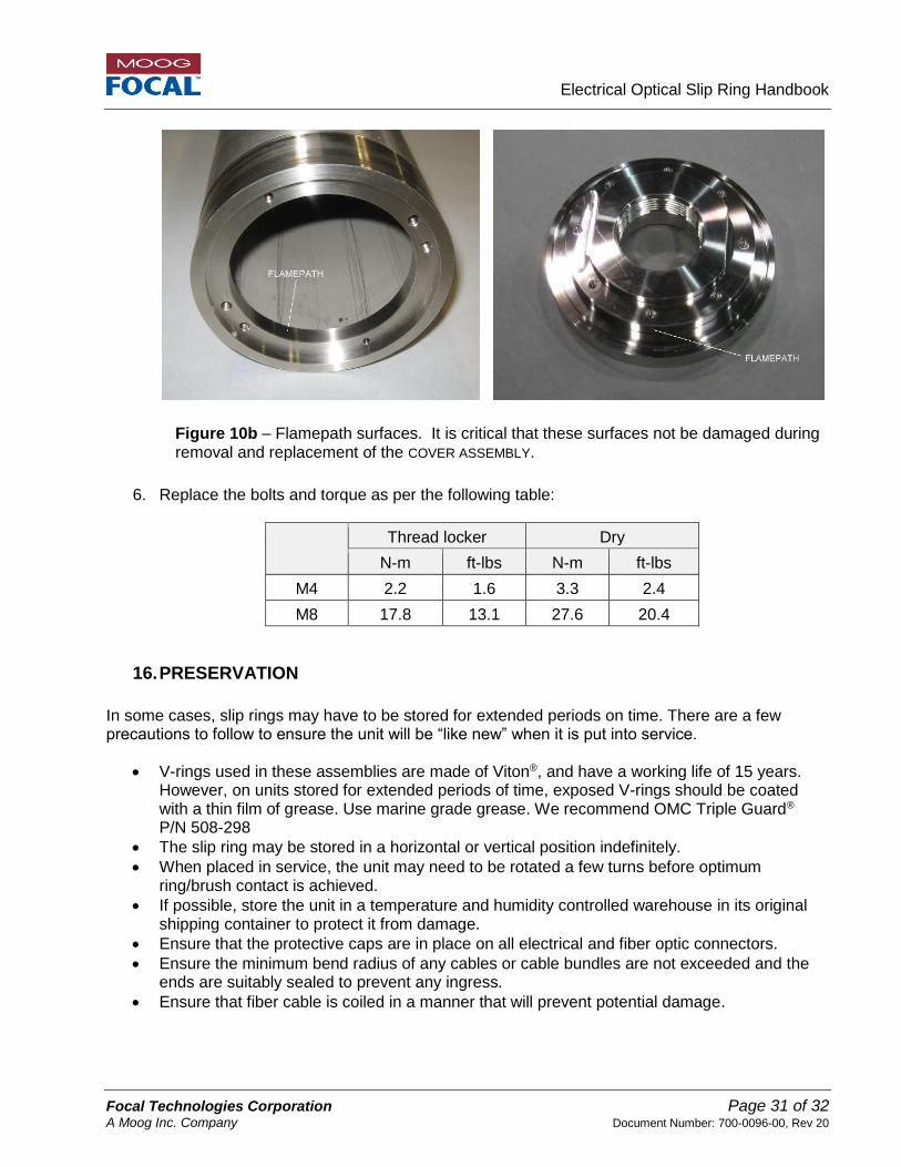
Figure 10a – Flamepath surfaces. It is critical that these surfaces not be damaged during removal and replacement of the COVER ASSEMBLY.
Electrical Optical Slip Ring Handbook
Focal Technologies Corporation Page 31 of 32 A Moog Inc. Company Document Number: 700-0096-00, Rev 20
6. Replace the bolts and torque as per the following table:
Thread locker Dry
N-m ft-lbs N-m ft-lbs
M4 2.2 1.6 3.3 2.4
M8 17.8 13.1 27.6 20.4
16. PRESERVATION
In some cases, slip rings may have to be stored for extended periods on time. There are a few precautions to follow to ensure the unit will be “like new” when it is put into service.
V-rings used in these assemblies are made of Viton®, and have a working life of 15 years. However, on units stored for extended periods of time, exposed V-rings should be coated with a thin film of grease. Use marine grade grease. We recommend OMC Triple Guard® P/N 508-298
The slip ring may be stored in a horizontal or vertical position indefinitely.
When placed in service, the unit may need to be rotated a few turns before optimum ring/brush contact is achieved.
If possible, store the unit in a temperature and humidity controlled warehouse in its original shipping container to protect it from damage.
Ensure that the protective caps are in place on all electrical and fiber optic connectors.
Ensure the minimum bend radius of any cables or cable bundles are not exceeded and the ends are suitably sealed to prevent any ingress.
Ensure that fiber cable is coiled in a manner that will prevent potential damage.
Figure 10b – Flamepath surfaces. It is critical that these surfaces not be damaged during removal and replacement of the COVER ASSEMBLY.

Electrical Optical Slip Ring Handbook
Focal Technologies Corporation Page 32 of 32 A Moog Inc. Company Document Number: 700-0096-00, Rev 20
17. RETURN
A return authorization number (RAN) should be obtained from the factory before shipping the unit and care should be taken in repackaging. If the unit is to be returned to Focal, it should be repackaged in its original container. To request a Return Authorization Number (RAN) please contact Focal Technologies Corp.: Tel: +1 902 468 2263 Email: [email protected] The document package shipped with the unit contains a Return Product Detail Sheet. The Detail Sheet enables the end user to provide relevant information about the field use, such as time in the field, revolutions, speed and fault information. The information is then reviewed by the Service technician to properly service the unit and to provide feedback to the customer in the form of a Service Summary. Returned products for service are normally tested and inspected per the original test plans.
Cost of returning the product is at the Buyers expense per the warranty statement and should be packaged in the original shipping box when possible. The shipping box is designed for proper mounting of the unit and protects the unit under shock loading in transport. The shipping box is also designed for the minimum bend radius of the pigtail leads and violating the minimum bend radius may void the warranty of the product. Oil filled products should be completely drained of the oil and the pigtail exits blocked from leakage. All oil soaked shipping boxes must be replaced at the customer’s expense.
Always use protective caps on connectors and protect the unit from moisture ingress as necessary. If possible, return the unit with the original hardware and components. The Service Summary will indicate what components are not returned and the quotation for repair will incorporate those replacement parts. Unless otherwise instructed units are evaluated on a first come, first serve basis. The average lead time for evaluation is 7 business days and is dependent upon work loading.