Electrical Modeling for Faults Detection Based on Motor Current ...
12
Electrical Modeling for Faults Detection Based on Motor Current Signal Analysis and Angular Approach Aroua Fourati, Nabih Feki, Adeline Bourdon, Didier Rémond, Fakher Chaari and Mohamed Haddar Abstract Recently, Motor Current Signal Analysis (MCSA) appears as an effec- tive tool for fault diagnosis in rotating machinery and proved to be suf ficient for detecting localized mechanical faults in electromechanical systems operating in stationary conditions. In the case of non-stationary conditions, speed variations must be distinguished from angular velocity perturbation caused by the presence of a defect. In the framework of diagnosis of rotating machinery, angular approaches are well suited to make monitoring resistive to speed disturbances. This paper proposes a reformulation of the MCSA associated with angular approach in mod- eling multiphysic behavior. The resulting model described in this paper can be used to investigate of the influence of the Instantaneous Angular Speed (IAS) variations on the electrical responses of the whole rotating system. Keywords Motor current signal analysis condition monitoring Non-stationary conditions Rotating machines Angular approach A. Fourati (&) A. Bourdon D. Rémond LaMCoS UMR5259, CNRS, INSA-Lyon, University of Lyon, Lyon, France e-mail: [email protected]; [email protected] A. Bourdon e-mail: [email protected] D. Rémond e-mail: [email protected] A. Fourati N. Feki F. Chaari M. Haddar La2MP, National School of Engineers of Sfax, Sfax BP 1173-3038, Tunisia e-mail: [email protected] F. Chaari e-mail: [email protected] M. Haddar e-mail: [email protected] © Springer International Publishing Switzerland 2016 F. Chaari et al. (eds.), Advances in Condition Monitoring of Machinery in Non-Stationary Operations, Applied Condition Monitoring 4, DOI 10.1007/978-3-319-20463-5_2 15
-
Upload
truongduong -
Category
Documents
-
view
218 -
download
0
Transcript of Electrical Modeling for Faults Detection Based on Motor Current ...

Electrical Modeling for Faults DetectionBased on Motor Current Signal Analysisand Angular Approach
Aroua Fourati, Nabih Feki, Adeline Bourdon, Didier Rémond,Fakher Chaari and Mohamed Haddar
Abstract Recently, Motor Current Signal Analysis (MCSA) appears as an effec-tive tool for fault diagnosis in rotating machinery and proved to be sufficient fordetecting localized mechanical faults in electromechanical systems operating instationary conditions. In the case of non-stationary conditions, speed variationsmust be distinguished from angular velocity perturbation caused by the presence ofa defect. In the framework of diagnosis of rotating machinery, angular approachesare well suited to make monitoring resistive to speed disturbances. This paperproposes a reformulation of the MCSA associated with angular approach in mod-eling multiphysic behavior. The resulting model described in this paper can be usedto investigate of the influence of the Instantaneous Angular Speed (IAS) variationson the electrical responses of the whole rotating system.
Keywords Motor current signal analysis condition monitoring � Non-stationaryconditions � Rotating machines � Angular approach
A. Fourati (&) � A. Bourdon � D. RémondLaMCoS UMR5259, CNRS, INSA-Lyon, University of Lyon, Lyon, Francee-mail: [email protected]; [email protected]
A. Bourdone-mail: [email protected]
D. Rémonde-mail: [email protected]
A. Fourati � N. Feki � F. Chaari � M. HaddarLa2MP, National School of Engineers of Sfax, Sfax BP 1173-3038, Tunisiae-mail: [email protected]
F. Chaarie-mail: [email protected]
M. Haddare-mail: [email protected]
© Springer International Publishing Switzerland 2016F. Chaari et al. (eds.), Advances in Condition Monitoring of Machineryin Non-Stationary Operations, Applied Condition Monitoring 4,DOI 10.1007/978-3-319-20463-5_2
15

Contents
1 Introduction.......................................................................................................................... 162 Asynchronous Motor Model Formulation........................................................................... 173 Introducing Instantaneous Angular Speed Disturbances .................................................... 204 Results and Discussions ...................................................................................................... 215 Conclusion and Perspectives ............................................................................................... 24References .................................................................................................................................. 25
1 Introduction
Induction motors connected to mechanical systems are widely used in industrialapplications due to their robustness, their compactness, low cost and high degree ofreliability. Condition monitoring and diagnosis of these systems by detecting smallvariations of their dynamic behavior are among challenges to improve theiravailability. The use of stator current signals constitutes a non-intrusive method toacquire information necessary to diagnosing electromechanical systems and thus toensure effective monitoring. Many researches focused on this framework andproved the capacity of this method to explicit mechanical defect localized on theelectromechanical system related to the motor [1, 2]. In a previous work, [3] ananalytical model of an asynchronous motor has been proposed and proved thepossibility to detect pitting in a geared system operating under stationary condi-tions. The classical theory of these motors is based on the assumption that thecurrent produced by their stator winding is sinusoidally distributed in time. Thisassumption is limited to systems operating under stationary conditions. However, inreal cases, current components related to faults are confused to those resulting fromdynamic variations, and thus, are very difficult to extract without a dedicated signalprocessing. Moreover, some recent results in rotating machine monitoring haveproven that the shaft rotation speed contains dynamic responses of faulted com-ponents in now well-known Instantaneous Angular Speed (IAS) signal [4].
To overcome these difficulties of non-stationary operating conditions, forexample, velocity variations that can hide the appearance of defects on the currentsignal, angular approaches seems to be well suited. In [5], a new way of writingdifferential equations in rotating machines by translation into the angular domainwas proposed and proved the interest of angular sampling in rotating machines [6].When addressing the case of rotating machines operating under non-stationaryconditions, every time their rotating element passes through a disturbance, a per-turbation takes place. These perturbations are managed by the rotation periodicityof the machine whatever the overall rotational speed. This leads to the newassumption that the stator current is periodically distributed in reference with theangular position of the shaft of rotating machines.
16 A. Fourati et al.
In this paper, the authors’ purpose is to develop a new approach to investigatethe MCSA method on electromechanical systems operating under non-stationaryconditions in order to analyze in a more efficient way the information given bystator currents for the detection of defects. Firstly, stator’s current and torqueresponses of a healthy motor are presented under this new formalism. In a secondstep, the proposed study is extended to present the responses under two differentexcitations mechanisms which are varying IAS due to the presence of bearingfaults.
2 Asynchronous Motor Model Formulation
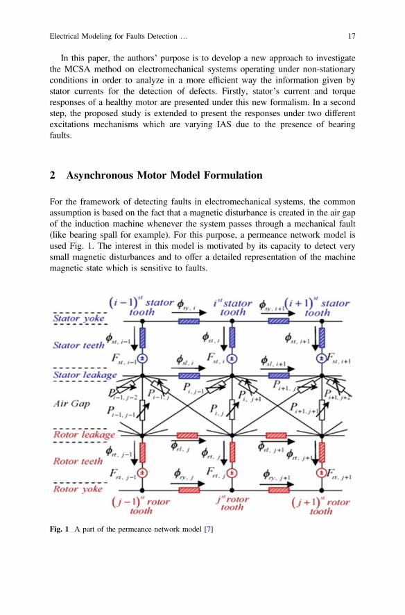
For the framework of detecting faults in electromechanical systems, the commonassumption is based on the fact that a magnetic disturbance is created in the air gapof the induction machine whenever the system passes through a mechanical fault(like bearing spall for example). For this purpose, a permeance network model isused Fig. 1. The interest in this model is motivated by its capacity to detect verysmall magnetic disturbances and to offer a detailed representation of the machinemagnetic state which is sensitive to faults.
Fig. 1 A part of the permeance network model [7]
Electrical Modeling for Faults Detection … 17

In order to simulate its magnetical behavior, the induction machine is discretizedon a finite number of nodes. In The overall network, Nn nodes are uniformlydistributed. Between each two node there is a branch representing flux circulation.Each flux tube is characterized by its permeance. Permeances in the stator and therotor are supposed to be constants whereas permeances of the air-gap are varying.In the complete permeance network model, there are Nb branches and Nbent bran-ches in the gap, these numbers are relative to the stator teeth and the rotor numbersns and nr, where Nbent ¼ ns � nr and Nb ¼ 3ns þ 3nr þ Nbent:
Where /sy;i, /st;i, /sl;i, /ry;j, /rt;j and /rl;j are stator yoke, stator teeth, statorleakage, rotor leakage, rotor teeth and rotor yoke flux. Fst;i and Frt;j are stator teethand rotor teeth magnetomotive forces. Pi;j is the air-gap permeance which connectthe ith stator tooth and the jth rotor tooth.
In the temporal domain, an induction machine is modeled using a unique dif-ferential equation combining its electrical and magnetical behavior as following [7]:
Lt½ �ðnphþnr ;nphþnrÞþ G tð Þ½ �ðnphþnr ;nphþnrÞh i d I tð Þf gðnphþnr ;1Þ
dt
þ Rt½ �ðnphþnr ;nphþnrÞþd G tð Þ½ �ðnphþnr ;nphþnrÞ
dt
" #I tð Þf gðnphþnr ;1Þ¼ V tð Þf gðnphþnr ;1Þ
ð1Þ
where I tð Þf g is the generalized stator and rotor current vector, V tð Þf g is the statorand rotor voltage supply vector, Lt½ � and Rt½ � are respectively matrix of inductancesand resistances of the rotor and the stator, nph and nr are respectively the number ofstator phases and the number of rotor teeth and G tð Þ½ � is the matrix describing theelectro-magnetical behavior of the induction machine.
These parameters will be involved to calculate the G tð Þ½ � matrix. In this modelwe consider stator and rotor permeances as constant whereas permeances on theair-gap depend dynamically from the angular displacement between the stator andthe rotor as shown in Fig. 2. This consideration induces the angular-dependingcharacter of the induction machine.
Fig. 2 Evolution of theangular position between acouple of stator and rotorteeth
18 A. Fourati et al.

For each couple of teeth; ith stator tooth and jth rotor tooth, the value of thepermeance is updated for every rotor position relatively to the following expression[8]:
P hij� � ¼
Pmax if 0� hij � ht1 and 2p� ht1 � hij � 2p
Pmax1þcos p h�ht1
ht�ht12 if ht1 � hij � ht
Pmax1þcos p
h�2pþht1ht�ht1
2 if 2p� ht � hij � 2p� ht10 if ht � hij � 2p� ht
8>>>><>>>>:
ð2Þ
where h is the rotor angular displacement relatively to the stator, hij the jth rotortooth rotational displacement referring to ith stator tooth, ht and ht1 are limit anglesrepresenting the angular variation of the permeance and Pmax is the maximal valueof the permeance of any couple of teeth.
The expression of Pmax depends on geometrical characteristics of the motor. It isdefined as:
Pmax ¼ l0LmLdre
ð3Þ
where l0 is the air-gap permeability, Lm is the machine length, Ldr is the rotor toothwidth and e is the air-gap thickness.
The starting point of the classical temporal approach for modeling the motor isbased on the fact that the temporal variable is linearly coupled to the angularvariable through a constant rotating speed as provided by Eq. (4), and then mod-eling will be limited to a stationary operating conditions system.
h ¼ xt ð4Þ
To overcome these limitations, we proceeded by an angular sampling. Thisapproach was well defined in [4]. Let h be the angular position of the rotor. Fornon-stationary rotating machines, the relation which links temporal to angularvariables is provided by means of the IAS function ~x as following:
dtdh
¼ 1~x hð Þ ð5Þ
Then, a reformulation of the permeance network model used to calculate vari-ations of current signals in the case of an asynchronous motor in an angular domainis proposed as following:
Electrical Modeling for Faults Detection … 19

Lh½ �ðnphþnr ;nphþnrÞþ G hð Þ½ �ðnphþnr ;nphþnrÞh i d I hð Þf gðnphþnr ;1Þ
dh~x hð Þ
þ Rh½ �ðnphþnr ;nphþnrÞþd G hð Þ½ �ðnphþnr ;nphþnrÞ
dh~x hð Þ
" #I hð Þf gðnphþnr ;1Þ¼ V tð Þf gðnphþnr ;1Þ
dtdh
¼ 1~x hð Þ
8>>>>>>>><>>>>>>>>:
ð6Þ
In order to minimize the number of equations and the dependence on the angularvariable, a basis change is defined. If we consider a relative frame whose axes arerotating in accordance with the rotor angular displacement, resulting projectedcurrents are obtained according to the relation:
Id hð ÞIq hð Þ
� �¼
ffiffiffi23
rcos xstð Þ cos xst � 2p
3
� �cos xst þ 2p
3
� �� sin xstð Þ � sin xst � 2p
3
� � � sin xst þ 2p3
� �� ��
I1 hð ÞI2 hð ÞI3 hð Þ
8<:
9=;ð7Þ
Coupling the electrical model of the induction machine to a mechanical model ofa defective system, the magnetic torque is expressed as:
Cem hð Þ ¼ 12
Xnsi
Xnrj
dPij
dhe2ij ð8Þ
where ns and nr are respectively stator and rotor tooth number, Pij and eij arerespectively the permeance and the magnetic potential difference in the air-gapwhich connects the ith stator tooth and the jth rotor tooth; Then it must be noticedthat differential equations expressed in the angular domain are nonlinear but withparameters which can be explicitly calculated, therefore decreasing calculationtime.
3 Introducing Instantaneous Angular Speed Disturbances
Comparing to temporal domain, in the differential Eq. (6) the rotational speedappears explicitly written in the angular domain. This allows integrating a distur-bance of the IAS in the model, this dynamic behavior being proven to be inducedby typical bearing faults. The form of the disturbance is inspired from the modeldeveloped in [9] as a function of the angular position of the shaft. The expressionproposed to characterize the disturbance is defined as a periodic function; eachoccurrence is divided into 3 areas as shown in Fig. 3:
20 A. Fourati et al.

Area1: Dx hð Þ ¼ xp sinpLp
h� h1 þ L2
Area2: Dx hð Þ ¼ 0
Area3: Dx hð Þ ¼ xp sinpLp
h� h3ð Þ ð9Þ
where xp and Lp are respectively the amplitude and angular length of theperturbation.
4 Results and Discussions
In order to show results of the motor current signal analysis (MCSA) methodcoupled to the angular approach, current signal of a machine has been simulatedwithout and with IAS perturbations. The considered model is a 50 kW, 50 Hz,400 V, 2 poles, 24 stator slots, 30 rotor slots, star connected, standard squirrel cageinduction motor rotating at a stationary speed x ¼ 300 rad/s.
Figure 4 shows a sinusoidal stationary variation of the stator first phase current.When projected onto d-axis, the combination of the three phase currents oscillatesstationary Fig. 5. Theses oscillations appear due to discontinuities of the magneticflux passing through the stator and rotor slots. Although the motor is currentlyworking in stationary conditions, we can, also notice some perturbations in thetorque curve Fig. 6. These perturbations are about 8 % of the torque value anddepend of geometrical parameters of the motor.
After adding the perturbation function to the constant rotational speed as recalledin Fig. 7, the stator first phase current variations Fig. 8, the projection of statorcurrents Fig. 9 and the torque Fig. 10 versus angular position of the rotor arepresented.
Through these figures, it was shown that a perturbation may not appear in eitherthe stator per phase current or the torque curve. On the contrary, it appears clearlyas a periodic perturbation in the d-axis projected signal. This perturbation appearseach time a speed perturbation takes a place. It was proven through this graph that a
Angle
Spe
ed p
ertu
rbat
ion Area 3Area 2Area 1
Fig. 3 Angular variation of the disturbance function
Electrical Modeling for Faults Detection … 21

70 70.5 71 71.5 72 72.5 73 73.5 74 74.5 75
-100
0
100
Angle [rev]
Sta
tor
curr
ent [
A]
Fig. 4 Stator current versus angle of rotation for a constant rotational speed x ¼ 300 rad/s
70 70.5 71 71.5 72 72.5 73 73.5 74 74.5 75
115
120
125
Angle [rev]
Tor
que
[N.m
]
72 72.1 72.2 72.3 72.4 72.5 72.6 72.7 72.8 72.9 73
115
120
125
Angle [rev]
Tor
que
[N.m
]
Fig. 6 Torque and zoom of the torque for a constant rotational speed x ¼ 300 rad/s
70 70.5 71 71.5 72 72.5 73 73.5 74 74.5 7560.5
61
61.5
62
Angle [rev]
d-ax
is c
urre
nt [A
]
72 72.1 72.2 72.3 72.4 72.5 72.6 72.7 72.8 72.9 7360.5
61
61.5
62
Fig. 5 d-axis current and zoom of the d-axis current for a constant rotational speed x ¼ 300 rad/s
22 A. Fourati et al.

very small perturbation in the rotation speed can be distinguished in the projectedsignal, proving the capacity of this method to small faults detection. It remains toaddress the sensitivity of the method to the perturbation amplitude.
The simulation demonstrates also the importance of considering angular domainfor modeling the motor in term of computation time. A comparison between model
70 70.5 71 71.5 72 72.5 73 73.5 74 74.5 75
0
2
4
6
Angle [rev]
Spe
ed p
ertu
rbat
ion
[rad
/s]
Fig. 7 Stator current versus angle of rotation for a disturbed rotational speed
70 70.5 71 71.5 72 72.5 73 73.5 74 74.5 75
-100
0
100
Angle [rev]
Sta
tor
curr
ent [
A]
Fig. 8 Stator current versus angle of rotation for a disturbed rotational speed
70 70.5 71 71.5 72 72.5 73 73.5 74 74.5 7560.5
61
61.5
62
Angle [rev]
d-ax
is c
urre
nt [A
]
72.5 72.6 72.7 72.8 72.9 73 73.1 73.2 73.3 73.4 73.560.5
61
61.5
62
Angle [rev]
d-ax
is c
urre
nt [A
]
Fig. 9 d-axis current and zoom of the d-axis current for a disturbed rotational speed
Electrical Modeling for Faults Detection … 23

runs in time and angular domains was performed for 1 s of a stationary motorrotation. Through this comparison is noticed that using angular domain reduce 70 %of the simulating time. This is justified by the fact that a large part of the numericalcalculation was performed analytically. In fact, angular modeling allows deter-mining the instantaneous angular variation of each coefficient of the G hð Þ½ � matrixand its derivate with respect to angle. Regarding these coefficients, it is noticed thatthey are depending on angularly periodic functions independently of the rotationspeed. This ascertainment strengthens our angular approach to modeling.
5 Conclusion and Perspectives
The work presented in this paper is an extension of a previous one aimed toformulate an analytical modeling of the MCSA for systems operating under sta-tionary conditions. By introducing angular approach in classical models, an originalreformulation of the method is presented to make it available for rotating systemsoperating under non-stationary conditions. The validation of this new methodologyimproves the use of MCSA. It also emphasizes the potential of the angular approachto solve non-stationary problems and extend its application on electrical machines.Results for constant and disturbed angular speed of the motor shows the importanceof dealing with non-stationary conditions to get effective monitoring.
From a modeling viewpoint, coupling the electrical model with a mechanical oneseems to be a natural extension of the present work in order to simulate pertur-bations induced by the presence of a fault on stator current signals.
Acknowledgements Authors gratefully acknowledge Rhone-Alpes Council support via mobilitygrant “Acceuil Doc” 13722.
70 70.5 71 71.5 72 72.5 73 73.5 74 74.5 75
115
120
125
Angle [rev]
Tor
que
[N.m
]
72.5 72.6 72.7 72.8 72.9 73 73.1 73.2 73.3 73.4 73.5
115
120
125
Angle [rev]
Tor
que
[N.m
]
Fig. 10 Torque and zoom of the torque for a disturbed rotational speed
24 A. Fourati et al.

References
1. Blodt M, Granjon P, Raison B, Rostaing G (2008) Models for bearing damage detection ininduction motors using stator current monitoring. IEEE Trans Ind Electron 5(4)
2. Rajagopalan S, Habetler TG, Harley RG, Sebastian T, Lequesne B (2006)Current/voltage-based detection of faults in gears coupled to electric motors. IEEE Trans IndAppl 42(6)
3. Feki N, Clerc G, Velex Ph (2013) Gear and motor fault modeling and detection based on motorcurrent signal analysis. Electr Power Syst Res 95:28–37
4. Renaudin L, Bonnardot F, Musy O, Doray JB, Rémond D (2010) Natural roller bearing faultdetection by angular measurement of true instantaneous angular speed. Mech Syst SignalProcess 24(7):1998–2011
5. Bourdon A, André H, Rémond D (2010) A new way of writing motion equations in rotatingmachines by translation into the angular domain. In: Proceedings of the 8th IFToMMinternational conference on rotor dynamics, KIST, Seoul, Korea, 12–15 September 2010
6. Rémond D, Antoni J, Randall RB (2014) Editorial for the issue on instantaneous angular speed(IAS) processing and angular applications. Mech Syst Signal Process 44:1–4
7. Feki N (2012) Modélisation électro-mécanique de transmissions par engrenages- Applications àla détection et au suivi des avaries, N° 2012 ISAL 0041 INSA of Lyon
8. Ostovic V (1989) Dynamics of saturated electric machines. Springer, New York9. Bourdon A, André H, Rémond D (2014) Introducing angularly periodic disturbances in
dynamic models of rotating systems under non-stationary conditions. Mech Syst Signal Process44:60–71
Electrical Modeling for Faults Detection … 25

http://www.springer.com/978-3-319-20462-8