Electrical Equipment - Course PI 30.2 MOTORS Library/20050713.pdf · field, of constant magnitude...
29
PI 30.24-1 Electrical Equipment - Course PI 30.2 MOTORS OBJECTIVES On completion of this module the student will be able to: 1. Briefly explain, in writing, "shaft rotation" as an interaction of stator and rotor magnetic fields. 2. Draw and properly label the characteristic curves of the squirrel cage induction motor for: a) torque vs speed; b) current vs speed. 3. Explain briefly, in writing, the follOWing terms, as related to a squirrel cage induction motor: a) Torque; b) Starting torque; c) Running torque; d) Pull out torque. 4. State, in writing, that the starting current is about· 6 x full load current. 5. Briefly explain, in writing, the following terms, as related to a squirrel cage induction motor: a) Motor full load current; b) Synchronous speed including the mathematical expression for synchronous speed; c) Slip speed, including the mathematical expression for slip speed. 6. Briefly explain, in writing, the meaning of the following nameplate data for a squirrel cage induction motor: a) HP b) RPM c) Volts d) Cycl es e) Amps f) Phase g) Service Factor h) Time rating i) Insulation Class j) Maximum Ambient Temperature January 1990 1 ITPO.OI
Transcript of Electrical Equipment - Course PI 30.2 MOTORS Library/20050713.pdf · field, of constant magnitude...

PI 30.24-1
Electrical Equipment - Course PI 30.2
MOTORS
OBJECTIVES
On completion of this module the student will be able to:
1. Briefly explain, in writing, "shaft rotation" as an interaction ofstator and rotor magnetic fields.
2. Draw and properly label the characteristic curves of the squirrelcage induction motor for:a) torque vs speed;b) current vs speed.
3. Explain briefly, in writing, the follOWing terms, as related to asquirrel cage induction motor:a) Torque;b) Starting torque;c) Running torque;d) Pull out torque.
4. State, in writing, that the starting current is about· 6 x fullload current.
5. Briefly explain, in writing, the following terms, as related to asquirrel cage induction motor:a) Motor full load current;b) Synchronous speed including the mathematical expression for
synchronous speed;c) Slip speed, including the mathematical expression for slip speed.
6. Briefly explain, in writing, the meaning of the following nameplatedata for a squirrel cage induction motor:a) HPb) RPMc) Voltsd) Cycl ese) Ampsf) Phaseg) Service Factorh) Time ratingi) Insulation Classj) Maximum Ambient Temperature
January 1990 1 ITPO.OI

PI 30.24-1
6. k) CEMA Designation1) Framem) Type.
7. Recall, and briefly explain the two basic types of enclosures forsquirrel cage induction motors and give an application for each type.
8. In writing, briefly discuss the difference between the two methodsof cooling used in each type of motor enclosure.
g. Briefly, in writing, state the consequence of changing the phasesequence, in a three phase induction motor.
2 ITPO.OI

PI 30.24-1
1. Introduction
This lesson will introduce the reader to:
(a) What is a motor.(b) Introduction to basic motor theory.(e) Motor characteristics.Cd) Motor nameplate data.Ce} Motor cooling.
2. What Is a Motor
A motor is an electromechanical device whichconverts electrical energy into mechanical energy.Input to the motor is electrical energy. Output fromthe motor is rotation of the motor shaft, whichdelivers the required torque to a load. Load on themotor can be anything that needs to be rotated.
3. Motor Theory
Refer to the explanation of magnetic affects ofelectrical current and principle of electromagneticinduction, in the lesson on "Generators".
3.1 Electromagnetic Force
Consider a conductor through which a current isflowing. See Figure 1, below.
Current going away from thereader, into the page. Current direction is representedby '+1 (tail of an arrow.)
Figure 1
- 3 -
Current coming towardsthe reader, out of thepage. Current direction is represented by1 , (head of arrow).

PI 30.24-1
3.1 Electromagnetic Force (continued)
Now consider a fixed magnetic field and aconductor carrying current placed in the magneticfield. See Figure 2.
CONDUCTOR CARRYING CURRENT
N s
MA<;lNET ----rMAGNETIC FIELDJ
Figure 2: Current Carrying Conductor in a Magnetic Field
The direction of current in the conductor, asshown, is away from the reader, into the page.
When the current flows through the conductor, amagnetic field is developed around the conductor.The direction of the magnetic field can be determinedby the right-hand rule. See Figures 3(A) and 3(B).
DIRECTION OF MAGNETIC FIELD
N S
Figure 3(A): Magnetic Field Around the Conductor
- 4 -

PI 30.24-1
3.1 Electromagnetic Force (continued)
Figure 3(B): Right hand Rule for determining Direction ofMagnetic Lines of Force around a Straight,Current-Carrying Conductor.
- 5 -

PI 30.24-1
3.1 Electromagnetic Force (continued)
Now there are two magnetic fields (think of themas two forces) namely:
(a) Magnetic field from the permanent magnet.(b) Magnetic field around the conductor due to the current
flow through it. Interaction of the two magneticfields is as follows:
At the top of the conductor, the two fields areadditive (in the same direction).At the bottom of the conductors, the two fields aresubtractive (in the opposite direction).
As a result, the conductor, if free to move, willmove in the downward direction. See Figure 4.
FIELDS
/ AIDING FIELDS
'>01N - ~ S~~
~OPPOSINGDIRECTION OF MOTION
Figure 4: Interaction of the Two Magnetic Fields and theResultant Direction of Motion
The above analysis can be applied, if thedirection of the current through the conductor ischanged. See Figure 5.
DIRECTION OF MOTION
N
OPPOSING FIELDS
s
AIDING FIELDS
Figure 5: Upwards Motion of Conductor With a Change inCurrent Direction
- 6 -

PI 30.24-1
Now consider a conductor in loop form. See Figure6. Note the following:
- Current from the supply goes through one side of theloop and returns through the other side. Hence, thedirection of current through each side of the loop isdifferent.
- The direction of magnetic fields around each side aredifferent.
- The direction of motion on each side is different.
If the conductor loop is mounted on a shaftthrough its centre as shown in Figure 6, and the shaftis mounted on bearings at the two ends, the conductorand the shaft will rotate.
DIRECTION OF CURRENT
S MAGNETIC FIELDaiding at the bottom
--- opposing at the top
DIRECTION OF MOTION
[DIRECTION OF ROTATION
II
II
I,-.lf
N
E-="L..-_-;
MAGNETIC FIELDaiding at the top
opposing at the bottom
SHAFT
CARBON BRUSH
Figure 6: Current Supplied to a Loop and The ResultingDirection of Motion
- 7 -

PI 30.24-1
3.1 Electromagnetic Force (continued)
The magnetic force produced, to cause the rotationof the shaft, is expressed below:
F(newtons) = B·I"L (do not memorize)
where: F is the force produced by the interaction ofthe two magnetic fields, in Newtons.
B is the magnetic flux density of the permanentmagnet, in Teslae.
L is the length of the conductor in themagnetic field, in metres.
I is the magnitude of current flow through theconductor in amperes.
The above presentation explains the operation of aDC motor.
- 8 -
PI 30.24-1
3.2 AC Motor
Mechanical motion is still produced in an AC motorby the interaction of two magnetic fields. However,how the two fields are obtained is different and isexplained in the sections below.
Rotating Magnetic Field
When a three phase supply is connected to thestator of an AC motor, a resultant rotating magneticfield, of constant magnitude is produced. For anexplanation, see Appendix A, at the end of this lesson(for information only).
3.3 Rotor Construction
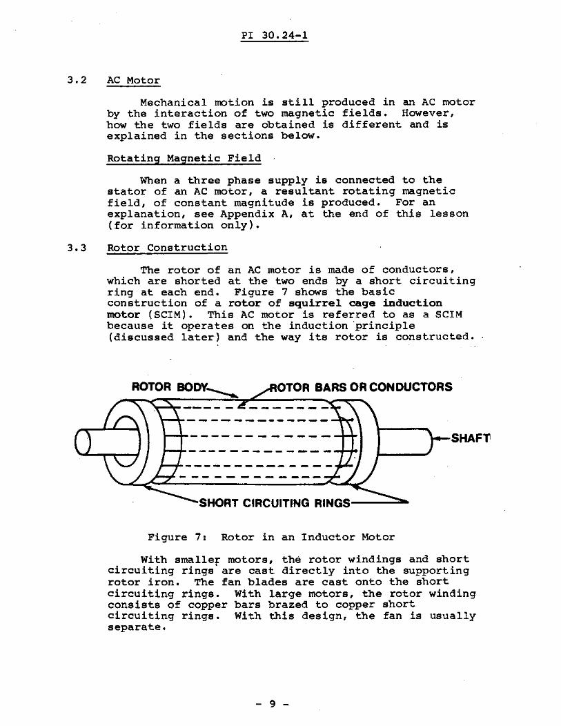
The rotor of an AC motor is made of conductors,which are shorted at the two ends by a short circuitingring at each end. Figure 7 shows the basicconstruction of a rotor of squirrel cage inductionmotor (SeIM). This AC motor is referred to as a gerMbecause it operates on the induction ·principle(discussed later-' and the way its rotor is constructed.
SHAFl'
OTOR BARS OR CONDUCTORS
SHORT CIRCUITING RINGS--....;:::...
------------
------------
ROTOR BODY__
Figure 7: Rotor in an Inductor Motor
With smaller motors, the rotor windings and shortcircuiting rings' are cast directly into the supportingrotor iron. The fan blades are cast onto the shortcircuiting rings. With large motors, the rotor windingconsists of copper bars brazed to copper shortcircuiting rings. With this design, the fan is usuallyseparate.
- 9 -

PI 30.24-1
3.4 Stator
The induction motor stator windings are insertedand wedged in slots punched in the laminated statoriron. This is a similar arrangement to that used in agenerator. The stator iron is securely clamped in theframe of the motor. The bearings are mounted in theend plates. Three phase input power lines areconnected to the respective stator windings in aterminal box.
3.5 Rotation of Shaft in an AC Motor
When a three phase supply is connected to thestator windings of an AC motor, a rotating magneticfield is produced, which continually rotates 360°. Therotation of this magnetic field constitutes a "relativemotion" between the motionless rotor conductors and ·themagnetic field. As a result, all the threerequirements (conductor, magnetic field and relativemotion) are met and a voltage is induced in the rotorconductors.
Since the rotor conductors are short circuited bythe short circuiting rings at the two ends, a current
.flows through the rotor conductors and produces its ownmagnetic field.
Interaction of the rotor magnetic field aqd thestator magnetic field produces the rotation of theshaft the same way as explained in Section 3.1
- 10 -

Cooling Fan
CbnvenleritWiring Access
Grease FIttings
PI 30.24-1
NameplateBearing Housing
Stator Frame
Mounting Base
IntegrallyCast Aotor
TEFC Endbell...or cast Iron e-Face.
Cutaway View of a serM (Squirrel Cage InductionMotor)
- 11 -

PI 30.24-1
4. Motor Torque
The tendency to produce rotation is referred to astorque. Figure 9 shows the torque-speed characteristic curves of a motor. The unit of torque is theNewton-meter. The motor running speed and the motorrunning torque is determined by the characteristics ofthe load which is coupled to the motor (i.e. a pump). Atypical load torque curve is also shown in Figure 9.The motor will always try to deliver" the exact amounttorque required by the load. This would be where themotor torque and load torque curves intersect.
TORQUE
MOTORRUNNING TORQUE
MOTORSTARTING TORQUE
__PULL OUT TORQUE
SPEED
Figure 9: Torque Speed Characteristic Curve of a Motor
- 12 -

PI 30.24-1
4. Motor Torque (continued)
4.1 Motor StartiDg' Torque: I t is the torque motordelivers when started from standstill position. It isalso referred to as locked rotor torque.
4.2 Motor Running Torque: It is the torque at which thedemanded by the mechanical load placed on the motor isequal to the torque produced by the motor. It is theequilibrium point between the mechanical load and themotor.
4.3 Motor PullOUt Torque: It is the maximum torquedeveloped by an induction motor at rated voltage andfrequency. If the torque demand is increased beyondthis.point, the motor will stall.
- 13 -

PI 30.24-1
5. Motor Current
Figure 10 shows a chracteristic curve of motorcurrent VB speed. Motor-full load current is thecurrent which the motor draws at the rated voltage,frequency, and torque.
MOTORSTARTING __1--- _CURRENT..... 1
MOTOR
~~~~~~~/----------------
o SPEED
Figure 10: Motor Current VB Speed Characteristics
From the curve shown in Figure 10 it can be seenthat the motor draws a large current at startingpoint. As the motor speed increases, current drawn bythe motor decreases.
Motor Starting Current is aboutthan the motor's full-load current.depends on the motor design.
- 14 -
sixThe
timesexact
largervalue

PI 30.24-1
6. Synchronous Speed
The speed of rotation of the stator magnetic fieldis called "synchronous speed n
• Synchronous speed, Nsis calculated by:
NS = Frequency revolutions/secNumber of Pole Pairs
7. Slip Speed
The rotor of the induction motor follows therotating magnetic field created in the stator. But,the rotor must always rotate slightly slower than themagnetic field, for the "relative motion" to takeplace. For idle running, this difference between thesynchronous and the actual rotor speed is very smalland depends on the friction and windage. Thedifference between the synchronous speed and the rotorspeed is called the slip speed or in short slip
Slip is expressed as a % of synchronous speed.Examine the expression below.
% Slip = Synchronous SpeedSynchronous
Rotor Speed x 100%Speed
If the rotor could rotate at synchronous speed,the slip would be zero. (This, however, does not occuras explained above). If the rotor is blocked fromrotating, the slip equals one or 100%.
- 15 -

PI 30.24-1
8. Motor Operation
Figure lO(B) has the previously mentioned motortorque and motor current VB. speed curvessuperimposed. Let us examine how they are related.
At stand still an induc~ion motor takes standstillor starting current and produces starting torque.Because the torque produced by the motor is greaterthan the torque required by the load. The motor andload speed will increase and the current falls. Motortorque will continue to increase until it produces itsmaximum attainable torque or pullout torque, at whichtime the torque will begin to decrease with increasingmotor speed.
The motor running speed, slip speed and normalrunning current are all determined at steady stateoperation. This is at the intersection of the motortorque curve and load torque curve.
As an exercise, the reader should be able tofollow the chain of events which would occur in a moto~
if the demanded load torque were to increase. Tovisualize this, consider the case where a motor wasdriving a water pump and the pump bearings are nowbeginning to dete~iorate.
Answer:
The motor would eventually burnout due toexcessive heat from current overload. Larger motorsare protected against this situation. This will bediscussed in the Motor Control section of these notes.
- 16 -

PI 30.24-1
STANDSTILL/CURRENT
--- ---- .... ....
"PULL OUT TORQUEMOTORTORQUECURVE
LOADTORQUECURVE
~_STEADY
STATE
...... MOTOR STARTINGTORQUE
II II ,I I
SLiP-. ...-
0---------50------ 100 -%SPEED100-...,------50----- --_0 - % SLIP
.RUNNING SPEED RMF SPEED
LOADSTARTING -~TORQUE
RUNNING -.TORQUE
Figure lOeB): Motor Torque and Motor Current Versus SpeedFor an Induction Motor
- 17 -

PI 30.24-1
6. Motor Nameplate Data
Motor nameplate data provides valuable informationabout the motor. Some of the most common data that themotor nameplate displays is given below:
Ca) HP:
(b) RPM:
(c) Volts:
(d) Amp,
(e) Cycles:
(f) Phase,
Indicates the horsepower rating ofthe motor.
Indicates the normal operating speedof the motor.
Indicates the normal operatingvoltage of the motor.
Indicates the normal operating fullload current of the motor.
Indicates the normal operatingfrequency of the power supplyconnected to the motor.
Indicates the type of motor - 3phase or single phase.
(9) Service Factor: Indicates how much overload aboveits nameplate rating the motor candeliver, continuously.
(h) Power Factor: Indicates the power factor of themotor at rated current, voltage andfrequency.
(i) Time Rating: ' Indicates the duty cycle, ie,frequency of start and stoppermitted for the motor. A motorrated as continuous duty cycle isnot suited for frequent starts andstops.
(j) Insulation Class: Letter associated with this ratingcorresponds to the temperaturerating of the insulation used in themotor. For further explanation seethe lesson on "Insulation".
- 18 -

PI 30.24-1
(k) Max Ambient Temp: >Each motor is rated to .operate at acertain maximum working temperature,at rated HP. This temperaturerating depends on the class ofinsulation used. The workingtemperatures are based on a standard40°C surrounding temperature,referred to as the ambienttemperature. If the ambienttemperature is more than thestandard 40°C, then the motor wouldhave to be derated, in terms of HP.
(1) CEMA Designation: Letter associated with thisdesignation indicates the motorspeed/torque characteristics, %slip, normal voltage, frequency andstarting current of the motor asstandardized by canadian ElectricalManufacturers Ass'ociation (CEMA).
(m) Frame: Number and letters associated withthis designation indicate thephysical dimensions of the frame, asstandardized by CEMA.
(n) Type: The letter designation associatedwith this information is themanufacturer's own designation forhis own recording convenience. Itwill vary from manufacturer tomanufacturer.
(0) Model: Numbers and letters associated withthis designation indicate the modelnumber for a particularmanufacturer.
(p) Serial Number: Indicates the serial number assignedto a particular motor.
- 19 -

PI 30.24-1
9. Ventilation System
In an induction motor, heat is produced in threemain areas:
(a) Stator Windings - Heating (I2R) is produced by thestator current flowing through the stator windings.
(b) Stator Iron - Heating is produced by eddy current andhysteresis losses.
(e) Rotor Windings - Heating (I2R) is produced by therotor current flowing through the rotor windings.Rotor iron core losses are negligable due to low rotorcurrents.
There are two basic types of enclosures, namely:
(a) Open.(b) Totally Closed.
In each type,motor application_,by air cooling.
variations exist dependingIn each case, the heat is
on theremoved
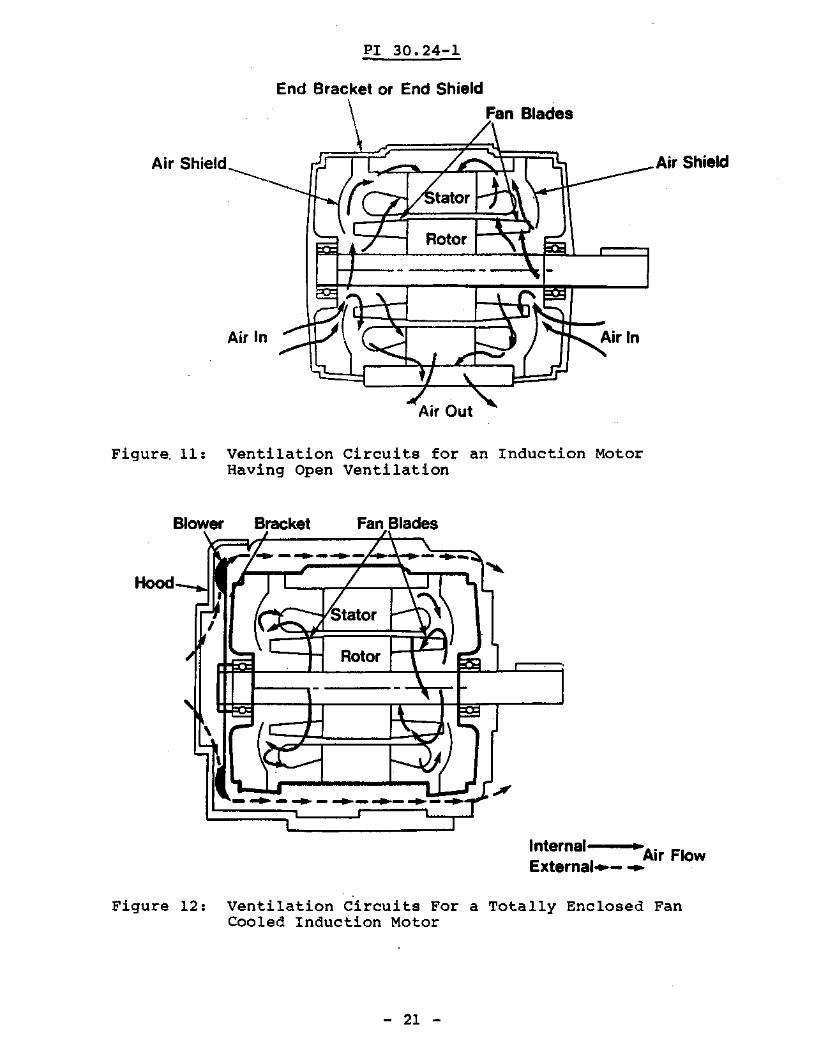
Figure 11 shows the ventilation circuits for aninduction motor having open ventilation. Outside airis brought in and circulated over the windings. Thistype of motor is not suitable for use in damp or dustyenvironments.
Figure 12 shows the ventilation circuitstotally enclosed fan cooled induction motor.there are two separate air circuits.
"for aNote that
The inner circuit is cooled by conduction throughthe casing.
The outer circuit cools the outer surface of thecasing.
This type of motor is suitable for use in damp ordusty environm~nts.
Ventilation of a motor must not be restricted.Any restriction in air flow will result in the motorgetting hotter and this may lead to a burn out.
- 20 -
PI 30.24-1
Air Shield
~---tator
Rotor
End Bracket or End Shield
Fan Blades
Air In
Air Shield
Figure. 11: Ventilation Circuits for an Induction MotorHaving Open Ventilation
., ";',
'L / \
I~ - ....-~- -~- ... ....- '" ) / 1.\ ..I :h: f£tator ~~L
, I
~~ I I Rotor I I
- -
" ~,
J It\ I '.
:r )
.. ," ......1[.#- ... - .... - ...- ..- ...- ...,
Blower Bracket Fan Blades
Hood
Internal • Air FlowExternal..- ~
Figure 12: Ventilation Circuits For a Totally Enclosed FanCooled Induction Motor
- 21 -

PI 30.24-1
Direction· of Rotation and Phase Sequence
10. Three phase power supply connected to the motormust be in the correct phase sequence to provide thecorrect direction of rotation. If any two leads of thepower supply connected to the three phase inductionmotor are interchanged, phase sequence will be reversedand the motor will rotate in the opposite direction.
- 22 -

PI 30.24-1
Notes
- 23 -

PI 30.24-1
ASSIGNMENT
1. What is a motor. What form of energy is i~put andoutput for a motor? (Section 2)
2. Explain how shaft rotation is obtained in a squirrelcage induction motor (SerM).
- 24 -

PI 30.24-1
3. What is the purpose of the short circuiting rings in therotor of a squirrel cage induction motor (BerM)?(Section 3.3)
4. Draw and properly label the following curves for an induction motor.
(a) Torque va speed.
(b) Current va speed.
- 25 -

PI 30.24-1
5. Define the following terms, as related to squirrel cageinduction motors. (Section 4)
(a) Torque
(b) Starting Torque
(e) Running Torque
(d) PullOut Torque
6. What is the relationship between the starting currentand the full load current in a squirrel cage inductionmotor (SCIM)?
- 26 -

PI 30.24-1
7. Define the following terms, as related to a squirrelcage induction motor:
(a) Motor full load current. (Section 5)
(b) Synchronous speed. (also give the mathematical expression to calculate synchronous speed of asquirrel cage induction motor) (Section 6)
(e) Slip speed. (also give the mathematical expressionto calculate the slip speed) (Section 7)
8. Interpret the following nameplate data for a squirrelcage induction motor. (Section 8)
(a) HP
(b) RPM
(e) Volts
- 27 -
PI 30.24-1
(d) Cycles
(e) Amp
(f) Phase
(g) Service Factor
(h) Power Factor
(i) Time Rating
(j) Insulation Class
(k) Maximum Ambient Temperature
(1.) CEMA Designation
(m) Frame
(n) Type
9. What two general types of motor enclosures areavailable. Give their respective applications.(Section 9)
- 28 -

PI 30.24-1
10. How do the two types of motor enclosures differ fromeach other, in providng cooling to the motor. (Section9)
11. What is the consequence of changing the phase sequence,in a three phase induction motor? (Section 10)
s. Rizvi
- 29 -