Electrical Blueprint Reading - JustAnswer · Electrical Blueprint Reading. 2 Electrical Blueprint...
71
Study Unit Electrical Blueprint Reading
Transcript of Electrical Blueprint Reading - JustAnswer · Electrical Blueprint Reading. 2 Electrical Blueprint...

Study Unit
Electrical Blueprint Reading

Pr
ev
iew
iii
Pr
ev
iew
In this study unit, you’ll learn to read several different types of electrical blueprints. Reading and understanding the infor-mation that appears on a blueprint will be emphasized, not the design details of a particular project. Blueprints are used to present electrical-system design information in a variety of ways. The general principles for preparing blueprints will also be covered. The skills you learn can be applied to reading blueprints for residential, commercial, manufacturing, and electric utility projects.
When you complete this study unit, you’ll be able to
• Explain how blueprints are prepared
• Talk about the relationship of electrical blueprints to the architectural drawingsand drawings of other trades
• Read and understand the information presented on blueprints
• Identify the different methods of presenting information on blueprints
• Interpret the common symbols used on electrical blueprints
• List the common abbreviations used on electrical blueprints
• Trace a wiring diagram and understand it
Co
nt
en
ts
v
Co
nt
en
ts
INTRODUCTION TO ELECTRICAL BLUEPRINTS 1Background 1Original Drawings and Tracings 2Procedures for Making Copies 3Layout of Drawings 5Dimensions 7
TYPES OF BLUEPRINTS 14Blueprint Details 14Schematic/Wiring Diagrams 16Bill of Material 20Schedules 23Lighting Plan and Power Plan 23Ancillary System Plans 23Electrical Symbols 24Wire Sizes 25
RESIDENTIAL PLANS 27The Electrician’s Job 27Lower Floor Plan (Basement) 27Main Floor Plan 29
EQUIPMENT DRAWINGS 32Extent of Coverage 32Motor Control 32Heating Control 34Programmable Logic Controller 36
MANUFACTURING FACILITY 43Site Plan 43Single-Line Diagram 45Lighting and Receptacle Plan 51Power and Signal Plan 53Wiring Diagram 55
SELF-CHECK ANSWERS 59
APPENDIX 61
EXAMINATION 55
1
INTRODUCTION TO ELECTRICAL BLUEPRINTS
BackgroundA blueprint is a photographic print of a prepared drawing with the lines and lettering in white on a bright blue back-ground; it’s used for mechanical, electrical, and architectural drawings. The term refers to the working drawing used by the architectural, engineering, and construction professions to represent the desired construction plans. You’ll encounter blueprints only when working with old plans, which gener-ally have now been converted to microfilm or microfiche to preserve the information they contain. Even though modern prints aren’t blue, you’ll often hear them called blueprints. This unit will use the terms blueprint, drawing, and prints interchangeably to talk about the documents used to convey electrical information.
Designers use blueprints and sketches to communicate architectural and engineering details of construction projects to the owners, constructors, operators, and decision makers. A designer, whether an engineer, an architect, or a planner, conveys the design plans using drawings and lists. Anyone who works in the construction industry, such as an electri-cian, or in the architectural or engineering professions, has to be skillful in reading and understanding what information is being conveyed on drawings. The same is true for anyone who operates and maintains physical facilities.
Electrical Blueprint Reading

Electrical Blueprint Reading2
The plans for construction projects consist of architectur-al drawings as well as mechanical and electrical drawings. Separate drawings depict the information for the different construction trades, making it easier for both the designers and the contractors to understand what’s desired.
In every branch of electrical work, there’s the need to read electrical blueprints. An electrician wiring a new building con-sults the blueprints. Blueprints show conduit sizes; the size, type, and number of conductors; and locations of panels, junc-tion boxes, receptacles, and switches. The assembler of electric instruments or machines in a manufacturing plant follows a blueprint to connect the internal parts correctly. Blueprints provide a reference for correct operation of electrical equip-ment in industrial plants. Another important use of electrical blueprints is in troubleshooting equipment-operating prob-lems. Maintenance and operating personnel test the circuits and components. Comparing the test results to the correct operation as defined by the blueprints helps to identify faulty installations or failed components.
To be able to “read” a blueprint, you must have a general understanding of architectural drawings and be familiar with the meaning of each symbol, line, and abbreviation on the print. That is, you must be able to interpret the message conveyed by the drawing.
Original Drawings and Tracings The preparation of an electrical drawing involves a consider-able amount of work, and thus the original drawing is very valuable. Owners and designers preserve the original drawing to make additions and corrections, if necessary, and to keep as a permanent record. The information on the drawing must be available to all persons who might need any information. Even if every interested person could conveniently refer to the original drawing, it would soon become badly worn and damaged, and possibly lost. Therefore, the usual procedure is to make exact copies or reproductions of the original drawing and distribute them to those who need the information on the drawing.
3Electrical Blueprint Reading
Designers prepare the original drawings manually or with the use of a computerized drawing program.
The present practice in the few drafting rooms that still pro-duce drawings manually is to make the original drawing in pencil directly on tracing paper or pencil cloth. Copies of these pencil drawings are reproductions or blueprints. The pencil drawings are easy to revise when necessary, and with reasonable care, they last for 30 years or even longer.
Currently, designers create most new drawings using a CAD (computer- aided design) system. Drawings generated by the CAD system convey the same information as pencil drawings. The only difference is that the designer used a computer to prepare the drawing. With a computer software program, the designer can perform the drafting operations faster than with the traditional method. Improved accuracy, fewer mistakes, and the ability to rotate, reduce, or enlarge the drawing or parts of the drawing are some of the benefits of CAD prepa-ration. Modern low-cost plotters easily print the final result, and copies are made from the original computer file or print. In addition, most drafting rooms maintain the data for the drawing in a computer file, enabling the reproduction of the original or a modified version at any time.
The information conveyed on drawings is the same regardless of the method used to prepare the drawing. Modern methods using various computer programs allow more rapid prepara-tion of the drawing and different techniques to clarify or present the required information.
Procedures for Making Blueprint CopiesBlueprint paper has one side coated with a chemical that’s soluble in water and is also sensitive to light. In other words, water will wash the chemical in its original condition off the paper, but exposing the paper to a bright light causes the chemical coating to undergo a change. Washing the paper with water where the coating was exposed to light causes the paper to be colored a dark blue.

Electrical Blueprint Reading4
Here’s how to make a blueprint: the tracing paper bearing the drawing is laid over a sheet of blueprint paper, with the treated side of the paper in contact with the tracing paper. Then, the two sheets are placed under a sheet of glass set in a frame, with the tracing paper next to the glass. The two sheets must be held in close contact. The tracing material, with the blueprint paper under it, is exposed to a bright electric light. The light passes through the transparent parts of the tracing material and acts on the chemical coating of the blueprint paper. The coating thus becomes insoluble, or fixed, and can’t be washed off. The lines, letters, and other marks made on the tracing material with pencil or ink pre-vent the light from passing through. They thus protect the chemical coating of the blueprint paper directly underneath, keeping it in its original condition, or water soluble.
After exposure to the light for a sufficient time, the tracing material and blueprint paper are removed. The blueprint paper is then washed or rinsed thoroughly in a tank or shallow pan of water. Those parts of the blueprint paper on which the chemical has been made insoluble by light retain a dark-blue color, but the parts protected from light are washed off by the water, leaving white lines and letters on blue paper. Certain chemicals can be mixed with the wash water to make the blue darker and the white lines more distinct or sharper.
The washed and dried print is used in the same way as the original drawing. It’s an exact copy of the original with respect to marks, size, and scale. Any number of prints can be made from the same tracing because the tracing isn’t affected in any way by the blueprinting process.
Many different processes can produce prints. There are pro-cesses to make prints with red, brown, blue, or black lines on white paper. The most common process results in blue lines on white paper. Photocopies or photostats of original draw-ings are made, which is the same as taking a picture of the original and printing copies from the negative. With the photographic process, reduced or enlarged copies of the original can be produced. The photocopy process is consid-erably more expensive than the blueprinting process, so it’s used only in special cases.
5Electrical Blueprint Reading
Layout of DrawingsThe size of a drawing depends on the nature and size of the objects drawn. No set rule fixes the size of the drawing sheet to use. However, the size should never be larger than neces-sary to show all that needs to be represented on the drawing. The larger sizes are used for general arrangements and for wiring diagrams, while the smaller sizes are used for details, bills of material, and conduit and cable lists.
Each drafting room or design firm has its own standard sizes of drawing sheets. The size depends on the type of work done in the drafting room, but there’s no one standard in all drafting rooms for a particular type of work. The size of the drawing sheet is usually designated by a letter; for example, in one drafting room, an A-size drawing may be 81/2 3 11 in. (inches); a B size, 11 3 17 in.; a C size, 14 3 20 in.; a D size, 20 3 26 in.; and an E size, 26 3 38 in. The letter is included on the drawing because each size drawing is filed in a sep-arate drawer or bin. In general, most firms will use E-size drawings for a project, and also use the drawing number to refer to the type of drawing; that is, E for the electrical drawings, P for the plumbing drawings, and so forth.
When drawing electrical construction prints by hand, the drafter generally uses a triangular-shaped ruler, called an architectural scale, to reduce or adjust the size of the draw-ing. This scale has graduations of 1/8, 1/4, 1/2, 3/4, and 1 in. to the foot. For location plans and small preliminary sketches, a scale of 1/8 in. to the foot is in general use. For the site plan, showing the general layout of a building or site, a scale of 1 in. = 20, 30, 40, 50, or 100 ft is in general use. Enlarged scales are used as required to clearly show a project’s details. All of these same relationships, between drawing and physical size, are also used when prints are drawn with a computer.
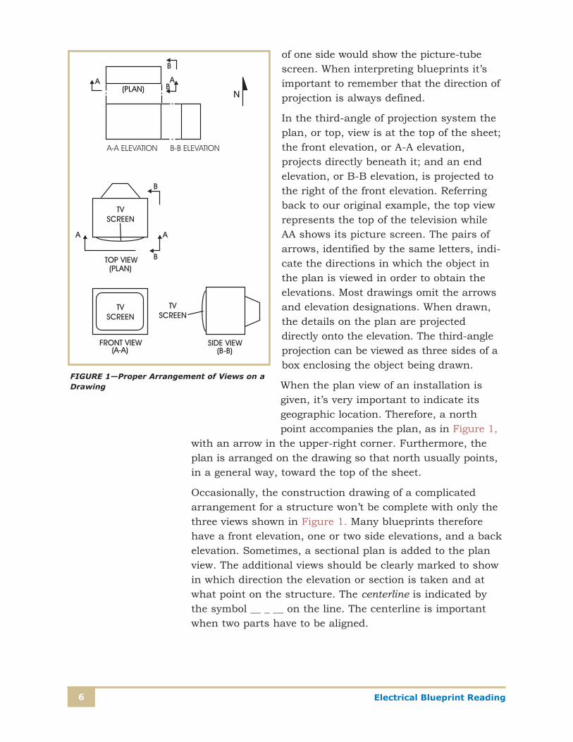
The arrangement of views on construction drawings is import-ant, particularly to the person who must read the drawing for details. The system used is the third-angle projection, shown in Figure 1. The term projection is an important one. Think of a projection as an alternative view of a pictured object. If your television is shown from above, for instance, the projected view
Electrical Blueprint Reading6
of one side would show the picture-tube screen. When interpreting blueprints it’s important to remember that the direction of projection is always defined.
In the third-angle of projection system the plan, or top, view is at the top of the sheet; the front elevation, or A-A elevation, projects directly beneath it; and an end elevation, or B-B elevation, is projected to the right of the front elevation. Referring back to our original example, the top view represents the top of the television while AA shows its picture screen. The pairs of arrows, identified by the same letters, indi-cate the directions in which the object in the plan is viewed in order to obtain the elevations. Most drawings omit the arrows and elevation designations. When drawn, the details on the plan are projected directly onto the elevation. The third-angle projection can be viewed as three sides of a box enclosing the object being drawn.
When the plan view of an installation is given, it’s very important to indicate its geographic location. Therefore, a north point accompanies the plan, as in Figure 1,
with an arrow in the upper-right corner. Furthermore, the plan is arranged on the drawing so that north usually points, in a general way, toward the top of the sheet.
Occasionally, the construction drawing of a complicated arrangement for a structure won’t be complete with only the three views shown in Figure 1. Many blueprints therefore have a front elevation, one or two side elevations, and a back elevation. Sometimes, a sectional plan is added to the plan view. The additional views should be clearly marked to show in which direction the elevation or section is taken and at what point on the structure. The centerline is indicated by the symbol __ _ __ on the line. The centerline is important when two parts have to be aligned.
FIGURE 1—Proper Arrangement of Views on a Drawing
7Electrical Blueprint Reading
DimensionsDimensions and distances are essential on all drawings except schematics. In fact, this is one of the major differenc-es between electrical blueprints and schematics. Although it’s true that most construction drawings are drawn to scale, it would be almost impossible for the construction worker to scale off every dimension needed for a project. It’s neces-sary, therefore, that dimensions be indicated on each view. In arrangement plans, it’s equally important to indicate the dimensions and distances of the entire installation.
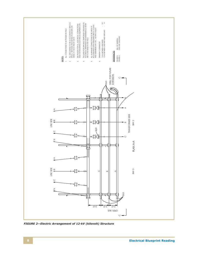
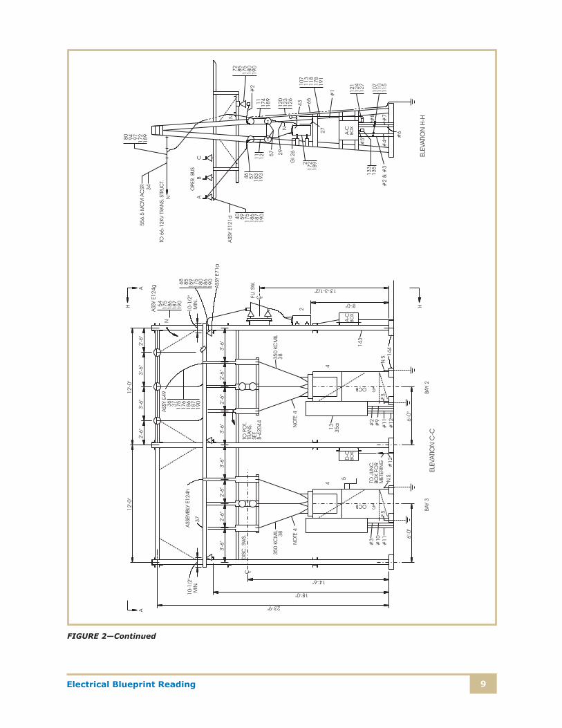
Dimensions and distances are measured from a fixed object, foundation, or ground line, and are taken to the centerline of the object to be located. For instance, refer to the left-hand side of Elevation C-C on Figure 2. Three disconnect switches are shown on the left side of the elevation. The centerline of the disconnect switches is referenced to the top of the foun-dation and is noted as 149 (feet)–60 (inches). The insulator (triangular symbol) just above is also tied to the foundation and the measurement given is 189– 00. It’s permissible, for instance, to show a dimension starting at a fixed point A, which may be the top of the foundation of a certain struc-ture, and extend up a pole or column to a point B to locate a certain object, and then continue to points C, D, and E, giving the dimension only between each two of these points. However, when this method is used, another dimension line is shown alongside these points, giving the total dimen-sion between points A and E. Again, in Elevation C-C, the dimensions for the disconnect switches are shown using this method. The centerline of the first switch is shown as 39–60, measured horizontally from the centerline of the left-hand steel member. The distance between switches is 29–60, measured from centerline to center line. Anyone reading the drawings shouldn’t have to total any dimensions to find out an overall working length. Note that a total horizontal dimen-sion 129–00 is given at the top of Bay 3, which is the sum of the dimensions between switches and from the switches to the upright members.
Dimension lines are placed on the outside of the object, with limit lines drawn into the object to indicate what’s to be located to that particular dimension. If it’s necessary to show
Electrical Blueprint Reading8
FIGURE 2—Electric Arrangement of 12-kV (kilovolt) Structure
9Electrical Blueprint Reading
FIGURE 2—Continued

Electrical Blueprint Reading10
a dimension within the outline of the object, the dimension is arranged so that it doesn’t conflict with any part of the object itself.
All dimension lines have arrowheads at both ends to indi-cate clearly the limits of the dimension line. The dimension is shown directly above the dimension line, or the line may be broken to permit the insertion of the dimension. When the dimension line is too short to permit the lettering of the dimension on it, it’s written at some convenient place near the line with a line or arrow directed to the proper dimension line.
In some drawings, all dimensions are expressed in inches and fractions of an inch, up to 72 in. (inches); in others, only up to 12 in. or 24 in. Above that, the dimension is expressed in feet and inches.
All dimensions are arranged so that they may be read from the bottom of the sheet or from the right. Thus, it’s never necessary to turn the drawing upside down to read it.
Dimensions not shown on the drawings or prints are usual-ly included on larger detail drawings or prints of the part or section; they’re also given in bills of material furnished to the constructor.
On practically every electrical drawing, certain notes are necessary to help the user complete the job represented by the blueprint. Frequently, certain information can’t be shown graphically on the drawing. However, it must be passed on to the user. Notes on the drawing serve that purpose, and are worded as briefly, but as completely, as possible.
Besides notes, references are made on the drawing to other drawings related to the job. On the construction drawing, for instance, references are made to the bill of material, wiring diagram, conduit schedule, panel schedule, and any other drawing that may be directly related. These references are generally placed below the notes and above the title.
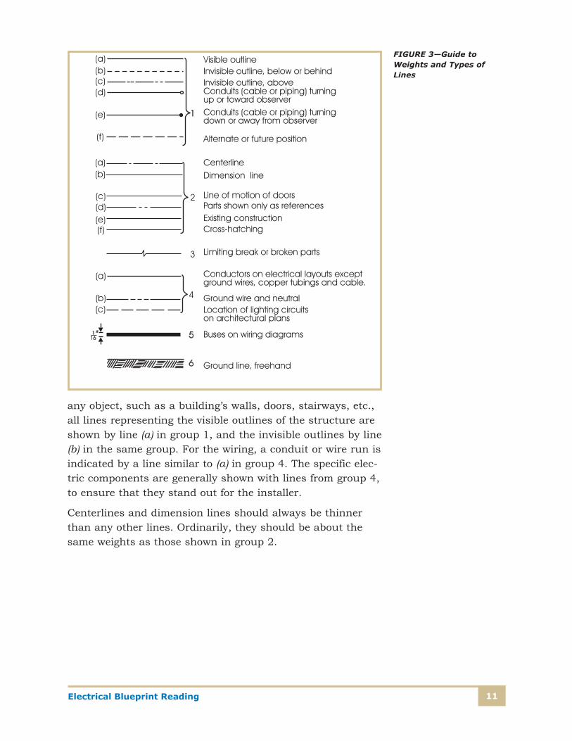
Whenever prints are drawn or interpreted, the weight and types for lines used are important. A guide to interpreting the weight and types of lines in drawing work is found in Figure 3. These lines aren’t standards; the examples given serve as a general guide to the different types of lines used on blueprints. For example, when a drafter draws the outline of
11Electrical Blueprint Reading
any object, such as a building’s walls, doors, stairways, etc., all lines representing the visible outlines of the structure are shown by line (a) in group 1, and the invisible outlines by line (b) in the same group. For the wiring, a conduit or wire run is indicated by a line similar to (a) in group 4. The specific elec-tric components are generally shown with lines from group 4, to ensure that they stand out for the installer.
Centerlines and dimension lines should always be thinner than any other lines. Ordinarily, they should be about the same weights as those shown in group 2.
FIGURE 3—Guide to Weights and Types of Lines

Electrical Blueprint Reading12
Titles are usually placed in the lower right-hand corner of the drawing sheet. However, the exact location of the title on the drawing may vary, depending not only on the particular type of drawing, but also on the preferences and standards used by the firm preparing the drawing. The title should include the name of the project, stating clearly what the drawing covers—a general-arrangement plan, elevations and details, a conduit plan, a wiring diagram, a panel schedule, a lighting plan, a fixture schedule, or a power plan. Also to be included are the scale, the date prepared, spaces for the final approval and the engineer’s seal, and the number of the drawing.

13Electrical Blueprint Reading
Self-Check 1
At the end of each section of Electrical Blueprint Reading, you’ll be asked to pause and check your understanding of what you’ve just read by completing a “Self-Check” exercise. Answering these questions will help you review what you’ve studied so far. Please complete Self-Check 1 now.
1. Why isn’t the original drawing issued to the construction personnel for installing electrical equipment?
__________________________________________________________
2. How are the electrical blueprints related to the architectural drawings of a project?
__________________________________________________________
__________________________________________________________
3. What changes have been made in the way drawings are prepared?
__________________________________________________________
__________________________________________________________
4. (a) Why are three views required to represent the arrangement of facilities?
__________________________________________________________
__________________________________________________________
__________________________________________________________
(b) Explain why additional views are sometimes necessary.
__________________________________________________________
__________________________________________________________
__________________________________________________________
5. What does a schematic drawing usually show?
__________________________________________________________
__________________________________________________________
Check your answers with those on page 59.
Electrical Blueprint Reading14
TYPES OF BLUEPRINTS
Blueprint DetailsElectrical blueprints are those drawings that deal mainly with the installation of electrical equipment in homes, commercial buildings, industrial plants, power plants, and utility substa-tions. With such widespread use, many other types of draw-ings and schedules are encountered. Some of the common drawings or schedules you’ll come across are
1. Electrical Construction Drawings
2. Schematic or Wiring Diagrams
• One-line diagram
• Three-line diagram
• Ladder diagram
3. Panel and Switchgear Drawings
4. Bill of Material
5. Schedules
• Panels
• Light fixture
• Motor
• Conduit and cable
6. Lighting and Power Plans
• Lighting
• Power
• Ancillary system
15Electrical Blueprint Reading
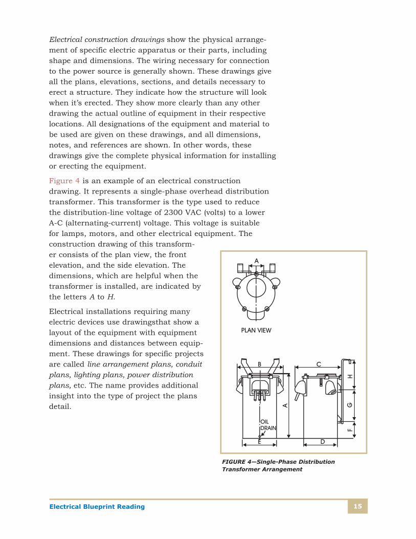
Electrical construction drawings show the physical arrange-ment of specific electric apparatus or their parts, including shape and dimensions. The wiring necessary for connection to the power source is generally shown. These drawings give all the plans, elevations, sections, and details necessary to erect a structure. They indicate how the structure will look when it’s erected. They show more clearly than any other drawing the actual outline of equipment in their respective locations. All designations of the equipment and material to be used are given on these drawings, and all dimensions, notes, and references are shown. In other words, these drawings give the complete physical information for installing or erecting the equipment.
Figure 4 is an example of an electrical construction drawing. It represents a single-phase overhead distribution transformer. This transformer is the type used to reduce the distribution-line voltage of 2300 VAC (volts) to a lower A-C (alternating-current) voltage. This voltage is suitable for lamps, motors, and other electrical equipment. The construction drawing of this transform-er consists of the plan view, the front elevation, and the side elevation. The dimensions, which are helpful when the transformer is installed, are indicated by the letters A to H.
Electrical installations requiring many electric devices use drawingsthat show a layout of the equipment with equipment dimensions and distances between equip-ment. These drawings for specific projects are called line arrangement plans, conduit plans, lighting plans, power distribution plans, etc. The name provides additional insight into the type of project the plans detail.
FIGURE 4—Single-Phase Distribution Transformer Arrangement
Electrical Blueprint Reading16
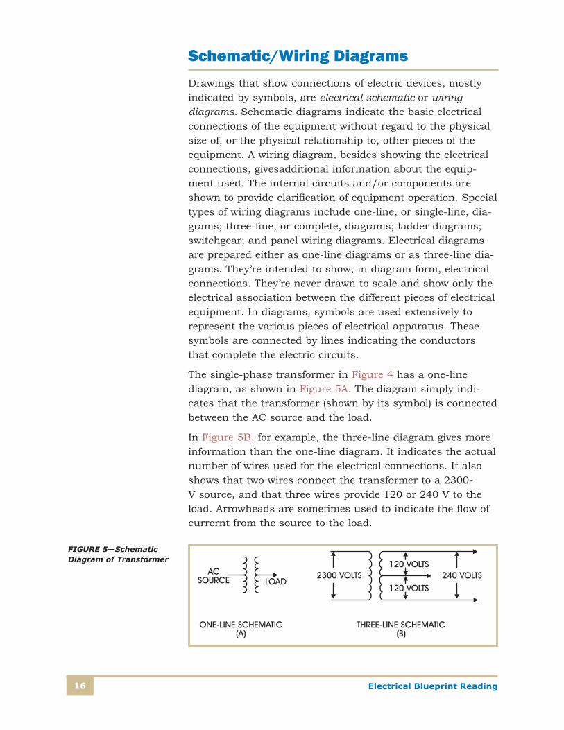
Schematic/Wiring DiagramsDrawings that show connections of electric devices, mostly indicated by symbols, are electrical schematic or wiring diagrams. Schematic diagrams indicate the basic electrical connections of the equipment without regard to the physical size of, or the physical relationship to, other pieces of the equipment. A wiring diagram, besides showing the electrical connections, givesadditional information about the equip-ment used. The internal circuits and/or components are shown to provide clarification of equipment operation. Special types of wiring diagrams include one-line, or single-line, dia-grams; three-line, or complete, diagrams; ladder diagrams; switchgear; and panel wiring diagrams. Electrical diagrams are prepared either as one-line diagrams or as three-line dia-grams. They’re intended to show, in diagram form, electrical connections. They’re never drawn to scale and show only the electrical association between the different pieces of electrical equipment. In diagrams, symbols are used extensively to represent the various pieces of electrical apparatus. These symbols are connected by lines indicating the conductors that complete the electric circuits.
The single-phase transformer in Figure 4 has a one-line diagram, as shown in Figure 5A. The diagram simply indi-cates that the transformer (shown by its symbol) is connected between the AC source and the load.
In Figure 5B, for example, the three-line diagram gives more information than the one-line diagram. It indicates the actual number of wires used for the electrical connections. It also shows that two wires connect the transformer to a 2300-V source, and that three wires provide 120 or 240 V to the load. Arrowheads are sometimes used to indicate the flow of currernt from the source to the load.
FIGURE 5—Schematic Diagram of Transformer
17Electrical Blueprint Reading
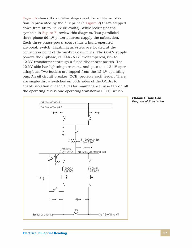
Figure 6 shows the one-line diagram of the utility substa-tion (represented by the blueprint in Figure 2) that’s stepped down from 66 to 12 kV (kilovolts). While looking at the symbols in Figure 7, review this diagram. Two paralleled three-phase 66-kV power sources supply the substation. Each three-phase power source has a hand-operated air-break switch. Lightning arresters are located at the connection point of the air-break switches. The 66-kV supply powers the 3-phase, 5000-kVA (kilovoltamperes), 66- to 12-kV transformer through a fused disconnect switch. The 12-kV side has lightning arresters, and goes to a 12-kV oper-ating bus. Two feeders are tapped from the 12-kV operating bus. An oil circuit breaker (OCB) protects each feeder. There are single-throw switches on both sides of the OCBs, to enable isolation of each OCB for maintenance. Also tapped off the operating bus is one operating transformer (OT), which
FIGURE 6—One-Line Diagram of Substation
Electrical Blueprint Reading18
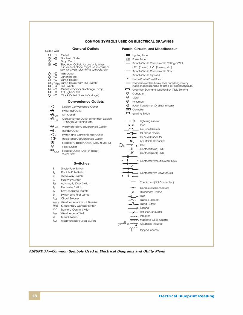
FIGURE 7A—Common Symbols Used in Electrical Diagrams and Utility Plans
19Electrical Blueprint Reading
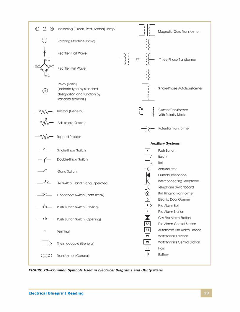
FIGURE 7B—Common Symbols Used in Electrical Diagrams and Utility Plans
Electrical Blueprint Reading20
can also be transferred to the other side of the OCB. A poten-tial transformer (PT) is tapped off the operating bus with a hot-line connector. The PT provides voltage measurement in the substation. Each OCB has current transformers (CTs) on the operating bus side used to measure current and con-nected to the protective relaying in the substation (not shown on the one-line diagram). The 12-kV lines each have lightning arresters on the line side of the OCBs. A normally open load-break disconnect switch is connected between the two feeders. This connection enables a supply to either line or both lines from one or the other breakers.
On many electrical blueprints, all the electrical diagrams are called wiring diagrams. The industry hasn’t established standard terms to refer to the various types of diagrams. In studying blueprints, you’ll soon acquire the ability to recog-nize whether a blueprint gives the wiring details or only a scheme of connections, regardless of the title used.
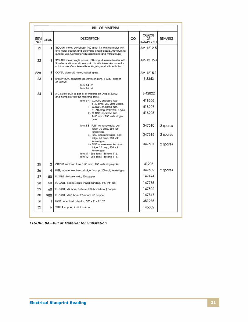
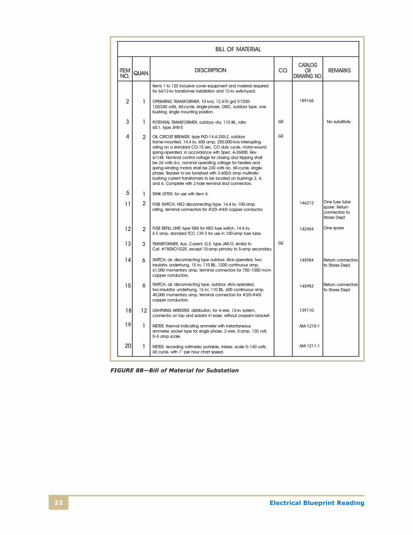
Bill of MaterialA bill of material is a tabulation of all the equipment required for a job. The various items are listed, and each item is assigned a number that also appears on the design drawing alongside, or as close as possible to, the item it represents. Small arrows are sometimes used to point to the items ref-erenced. The tabulations in a bill of material give a complete description of each item, the quantity required, the name of the manufacturer, and the catalog number, if any. A column is also provided for remarks, if necessary. Bills of material are usually made on separate sheets and assigned drawing numbers just as design drawings. Figure 8 gives you an idea of the bill of material for the substation shown in Figures 2 and 6.
With computer-generated drawings, it’s possible for the computer to tabulate the materials needed as the drawing is being prepared. The program then generates a list of materials as part of the design package.
21Electrical Blueprint Reading
FIGURE 8A—Bill of Material for Substation
Electrical Blueprint Reading22
FIGURE 8B—Bill of Material for Substation
23Electrical Blueprint Reading
SchedulesMost projects will have some schedules prepared. A schedule is a tabulation of the equipment required. The schedule differs from a bill of material in that it’s not just a tabulation of the material requirements. It also provides location infor-mation for the items, amount and size of the item required at each location, and clarification notes for each location, if needed. Types of schedules that you’ll encounter with electrical drawings are panel schedules, light fixture sched-ules, motor schedules, and conduit and cable schedules. By using schedules, the designer or drafter shows fewer details on the drawing, making it easier for the user to understand the basic plan.
Lighting Plan and Power PlanLighting and power plans are similar to the electrical con-struction drawings, but are used to show the lighting and power design plans for buildings. The lighting plan gives the physical placement of light fixtures, the source of power feeds, and the switching devices to be installed. The power plan shows the motors, motor controllers, power receptacles, and circuit feeds. Building electrical plans are separated into these two plans to make the drawings easier to under-stand and to reduce clutter on a drawing. They’re commonly referred to as lighting plan and power plan, rather than the more generic term construction drawings.
Ancillary System PlansIn modern offices, businesses, and industrial plants, many ancillary systems are installed. The design details for such systems as the fire alarm, communications, and energy management systems are shown on the same drawing as the electrical equipment. In many cases, there will be separate detail drawings for these systems. When reading prints that have these systems on the same drawings, the user should trace each system separately to avoid confusion.
Electrical Blueprint Reading24
Electrical SymbolsAll electrical diagrams make extensive use of symbols. Figure 7 lists some commonly used electrical symbols. They’re grouped by the type of equipment being shown. When reading blueprints, be alert to the various modifications to the base symbol, which must be properly interpreted. For example, the number of lines on a branch circuit line denotes the number of conductors being installed. In addition, as will be seen later in the example of a manufacturing plant, the designer notes the number of phase conductors, ground and neutral, by a longer mark and also uses a dot to denote a ground conductor. Basic symbols are also modified for use in three-line diagrams. The transformer symbol, for example, consists of two scalloped lines that represent the primary and the secondary winding. When this symbol is used to show a transformer in a one-line diagram, the line is connected to the center of each winding symbol, as shown in Figure 5A. When the same connection is shown in a three-line diagram, as in Figure 5B, the lines are connected at each end of the windings.
The types and ratings of devices represented by a symbol are often added adjacent to the symbol. For example, added to a transformer symbol used in a one-line diagram for a utility substation would be 5000 kVA, 3 phase, 60 cycle, 62,700–12,470 Y/7200 V. Some special conditions associated with the device may also be noted. Next to a receptacle outlet, GFCI would be added to denote that the particular receptacle is to be a ground fault circuit interrupter receptacle.
Designers and drafters use many abbreviations on electrical drawings. The abbreviations they use are based on the standard drawing abbreviations. The appendix at the back of this study lists some of the common abbreviations used on electrical drawings. Clarifications or explanations of other equipment or device abbreviations used on a particular draw-ing are found on the list of abbreviations for the particular project, in manufacturers’ manuals, or in the project’s bill of material.
Electrical switching equipment or electric devices are often referred to by numbers, with appropriate suffix letters (when necessary) according to the functions they perform. These

25Electrical Blueprint Reading
numbers are based on a system that has been adopted as standard by the American Standards Association (ASA). This system is often used in part, and sometimes in its entirety, on connection diagrams, in instruction books, and in specifi-cations. When reading or studying any electrical diagram or drawing in this study unit, you should refer to the appro-priate appendix. Not all symbols listed are used in the study unit, but as you encounter additional blueprints, you’ll find these symbols useful. It’s good practice to learn to recognize the common symbols by sight.
Although symbols have no standard sizes, you’ll find that most designers or drafters make them large enough to be recognizable. The size will vary according to the size and scale of the drawing and the amount of information being presented.
Wire SizesAs you know, wire sizes are specified by their American Wire Gage (AWG) number or their cross-sectional area, measured in thousand circular mils (Kcmils). For example, a wire that has a cross-sectional area of 500,000 circular mils is referred to as a 500-Kcmil wire. A #12 wire has a cross-sectional area of 6530 circular mils. Sizes generally used in building elec-trical systems include #14, through #1 to a #1/0 (a single 0), #2/0, #3/0, and #4/0. After #4/0, the sizes are referred to by their Kcmil size.

Electrical Blueprint Reading26
Self-Check 2
1–4: Indicate whether the following statements are True or False.
______ 1. Drawing symbols used on electrical drawings can be drawn only a standard way.
Designers can only adjust the symbol’s size.
______ 2. All electrical drawings are schematics.
______ 3. Wire sizes are determined by the cross-sectional area of the conductor.
______ 4. A set of electrical blueprints must have at least one of each type of drawing or
schedule to be a complete set.
5. What’s the difference between a one-line diagram and a three-line diagram?
__________________________________________________________
__________________________________________________________
Check your answers with those on page 59.
27Electrical Blueprint Reading
RESIDENTIAL PLANS
The Electrician’s JobThe set of electrical plans for an individual residence shows the various electrical devices (power panel, switches, recep-tacles, lights, doorbells, etc.) to be installed and the locations of the major appliances. A residential electrical plan generally doesn’t show the individual romex cables, or the routes the cables will take. What is generally shown with a dashed line is the connection of switches to individual light fixtures. It’s up to the electrician to determine the route of the cables.
Plate 1 shows the floor plan for a single-story residence with a partial basement. The required electric devices have been added to the plan. Standard symbols have been used. The electrician using the plan would add hand notes to show the various circuits and connections needed. A part of these notes is shown on Plate 1.
Lower Floor Plan (Basement)In the lower floor plan on Plate 1, the power panel is located along the north wall in the unfinished portion of the base-ment. A note provides the rating and size of the panel— 120/240-V, 200-A, 40-circuit panel with a main breaker. The service entrance conductors (rated for the 200-A service) are noted and are to be installed by the electrical contractor or electrician. These conductors go through a service discon-nect, from the electric service meter located on the front of the house to the panel. The electric service conductors are underground laterals from the electric utility’s pad-mounted transformer to the meter.
Receptacle locations are shown throughout the house, with special notes at the receptacles that must be GFCI protect-ed or that have a rating different from a 120-V, 15-A duplex receptacle.
Electrical Blueprint Reading28
The unfinished basement area has a 12.5-kW (kilowatt) air-conditioning unit, a 10-kW central heating unit, and a water heater. According to the National Electric Code (NEC), each of these devices requires a separate circuit and must originate in the panel. The electrician must verify the actual unit being installed to determine the conductor sizes needed and the cable routing from the units to the panel.
The lights in the unfinished area consist of a light fixture controlled by a switch located adjacent to the door, and two light fixtures that have individual pull chains to operate them.
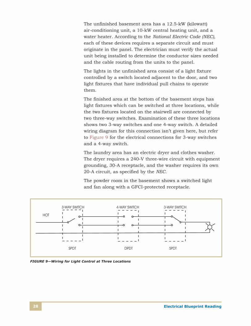
The finished area at the bottom of the basement steps has light fixtures which can be switched at three locations, while the two fixtures located on the stairwell are connected by two three-way switches. Examination of these three locations shows two 3-way switches and one 4-way switch. A detailed wiring diagram for this connection isn’t given here, but refer to Figure 9 for the electrical connections for 3-way switches and a 4-way switch.
The laundry area has an electric dryer and clothes washer. The dryer requires a 240-V three-wire circuit with equipment grounding, 30-A receptacle, and the washer requires its own 20-A circuit, as specified by the NEC.
The powder room in the basement shows a switched light and fan along with a GFCI-protected receptacle.
FIGURE 9—Wiring for Light Control at Three Locations
29Electrical Blueprint Reading
Main Floor PlanThe main floor on Plate 1 has a living room, dining area, kitchen, two baths, three bedrooms, and an entrance foyer. We’ll examine the wiring specified for a bedroom, a bath, the kitchen, and the living room.
Bedroom 1, the master bedroom, is representative of all the bedrooms. This bedroom also includes a bath. At the entrance to the bedroom, a switch controls the light in the hall into the bedroom. There’s also a switch for the light fix-ture in the closet. The bathroom has three switches, one for the light located in the center of the skylight, one for the light over the washbasin, and one to control the fan. The notation for the fan calls for a timed switch, the other switches are 120-V, single-pole switches. There’s a switch, located along the north wall of the bathroom, for a waterproof light fix-ture in the shower area. The receptacle located in the bath-room near the washbasin is a GFCI-protected receptacle, as required in all the bathrooms (by the NEC).
The bedroom has receptacles spaced around the room, fol-lowing the NEC recommendation that they be evenly spaced, with no wall location more than 6 ft from a receptacle. The room also has a ceiling light with a fan, each controlled by a separate switch. Smoke detectors aren’t shown in this drawing but must be installed in each bedroom and other locations as specified in the NFPA Standard No. 72.
The kitchen has all GFCI countertop receptacles supplied from at least two 20-A small-appliance branch circuits, as the NEC recommends. The receptacles around the countertop are to be installed so there’s no more than 24 in. of counter space to each receptacle. In addition, an outlet is required to serve each section of counter space that’s at least 12 in. long. The kitchen includes a 240-V, 50-A range receptacle, a power connection for the range hood fan and light, a separate branch circuit for the dishwasher, a switch and light over the sink, and a switch for the garbage disposal located under the sink. The ceiling light fixture in the kitchen is controlled by two 3-way switches, one located at each entrance to the kitchen.
Electrical Blueprint Reading30
The living room has receptacles regularly spaced, similar to other rooms in the house. To provide control of a light upon entry, two 3-way switches are used to provide switched control of one outlet of each of two duplex receptacles.
The NEC requires a residence to have an outdoor weath-erproof receptacle at the front and back of the home. Examination of the plan shows one located near the entry, and one located at the rear of the house. In addition, an outdoor receptacle is located on the side of the house at the patio.
The electrical plans for a residential dwelling must adhere to the National Electrical Code, which spells out very specifically the required branch circuits, and the number and locations of many receptacles. The designer should also identify on the plan the devices necessary for the convenience of the owner. The traffic flow and usage of the space will dictate many requirements.

31Electrical Blueprint Reading
Self-Check 3
Indicate whether the following statements are True or False.
______ 1. The range circuit provides power to the range hood.
______ 2. One helpful feature of properly drawn residential wiring plans is that the ideal cable
routes are well defined.
______ 3. The residential wiring diagram in Plate 1 calls for weatherproof receptacles to be placed
throughout the basement.
______ 4. Both three- and four-way switches will be installed at specified locations in the
residence shown in Plate 1.
______ 5. The residence shown in Plate 1 connects to the utility company’s power lines through a
traditional service drop service.
Check your answers with those on page 59.
Electrical Blueprint Reading32
EQUIPMENT DRAWINGS
Extent of CoverageYou’ll encounter many electrical components on blueprints where the designer assumes you have a basic understanding of the operation. Plans generally don’t show the internal ele-ments of electrical components or electric devices. Electrical blueprints will be easier to interpret if you (1) understand the operation of common components, (2) know what the internal elements of common components are, and (3) know where to get information for components that aren’t detailed on the construction drawings. Because of the large number of electrical components used by industries, businesses, and manufacturers, it’s impossible to identify all of them here. However, we’ll look at diagrams for a motor control, heating control, and programmable logic controller to provide you with some basic understanding of electrical components.
A schematic diagram is associated with all electrical compo-nents and is generally supplied with the device. In addition, manufacturer catalogs provide detailed drawings and electrical schematics. When components are actually being installed, it’s best to verify the connection as detailed on the schematics included with the equipment. Many times, manufacturers will have variations in the physical connection or installation, even though the basic operation is the same.
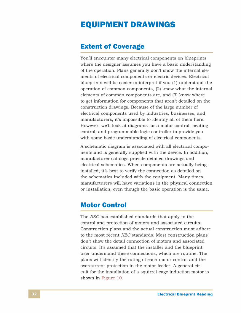
Motor ControlThe NEC has established standards that apply to the control and protection of motors and associated circuits. Construction plans and the actual construction must adhere to the most recent NEC standards. Most construction plans don’t show the detail connection of motors and associated circuits. It’s assumed that the installer and the blueprint user understand these connections, which are routine. The plans will identify the rating of each motor control and the overcurrent protection in the motor feeder. A general cir-cuit for the installation of a squirrel-cage induction motor is shown in Figure 10.
33Electrical Blueprint Reading
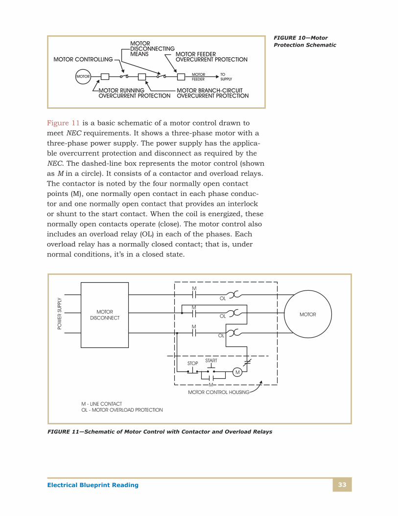
Figure 11 is a basic schematic of a motor control drawn to meet NEC requirements. It shows a three-phase motor with a three-phase power supply. The power supply has the applica-ble overcurrent protection and disconnect as required by the NEC. The dashed-line box represents the motor control (shown as M in a circle). It consists of a contactor and overload relays. The contactor is noted by the four normally open contact points (M), one normally open contact in each phase conduc-tor and one normally open contact that provides an interlock or shunt to the start contact. When the coil is energized, these normally open contacts operate (close). The motor control also includes an overload relay (OL) in each of the phases. Each overload relay has a normally closed contact; that is, under normal conditions, it’s in a closed state.
FIGURE 10—Motor Protection Schematic
FIGURE 11—Schematic of Motor Control with Contactor and Overload Relays
Electrical Blueprint Reading34
Let’s trace the normal operation of the motor control. When an operator presses the start button, which is a momentary contact, not a toggle switch, power is supplied to the control circuit. The line contactor coil (shown as an M in a circle) energizes, causing the contacts to close and energizing each of the phase conductors to the motor. In addition, the interlock contact closes, providing a shunt across the start button, maintaining an energized contactor coil, without the start button being held in an on position. The motor starts running. While the motor is running, if any of the phase overload relays detects a current that exceeds its set point, the overload relay operates, opening the normally closed contact. This action opens the control circuit, de-energizing the coil, with the result that each of the contacts opens. The motor will stop running. Correspondingly, for normal opera-tion, when an operator presses the stop button, the control circuit opens, again de-energizing the coil and causing each of the contacts to open.
This basic motor control circuit is typical. The motor control-lers and their associated circuits will vary among different models as well as different controller manufacturers. For a specific installation, it’s good practice to review the schematic that the manufacturer provides.
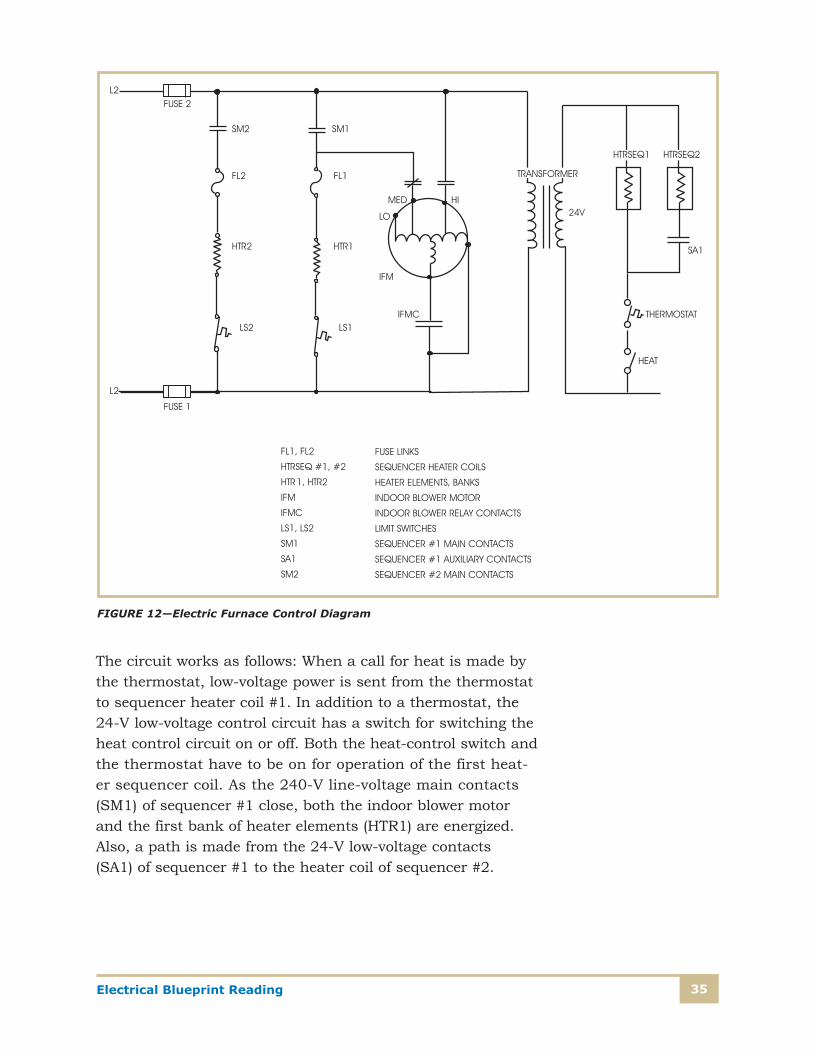
Heating ControlFigure 12 shows a schematic of an electric furnace control. This furnace has two heating elements and a blower motor. When the thermostat calls for heat, the heating elements are sequenced with a timed delay of 20 to 30 sec (seconds) before the energizing of the next element. The example shows only two elements, but many electric heaters have several ele-ments, with a timed delay before the energizing of each subsequent element.
35Electrical Blueprint Reading
The circuit works as follows: When a call for heat is made by the thermostat, low-voltage power is sent from the thermostat to sequencer heater coil #1. In addition to a thermostat, the 24-V low-voltage control circuit has a switch for switching the heat control circuit on or off. Both the heat-control switch and the thermostat have to be on for operation of the first heat-er sequencer coil. As the 240-V line-voltage main contacts (SM1) of sequencer #1 close, both the indoor blower motor and the first bank of heater elements (HTR1) are energized. Also, a path is made from the 24-V low-voltage contacts (SA1) of sequencer #1 to the heater coil of sequencer #2.
FIGURE 12—Electric Furnace Control Diagram
Electrical Blueprint Reading36
After a timed delay, usually 20 to 30 sec, the 240-V line- voltage contacts (SM2) of sequencer #2 close and power the second bank of heating elements (HTR2). If there are addi-tional heating elements, this sequencing would continue through a number of such sequencers, or through a stack sequencer control. A stack sequencer has one timed coil, but several sets of time-delayed contacts, each about 20 to 30 sec apart.
Each heater-element leg of the circuit is separately fused (FL1 or FL2), and has a thermal limit switch (LS1 or LS2) and the normally open line-voltage contact from the element’s sequencer coil.
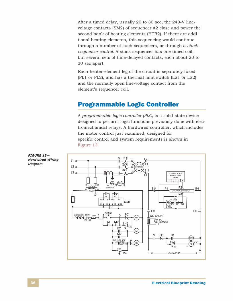
Programmable Logic Controller A programmable logic controller (PLC) is a solid-state device designed to perform logic functions previously done with elec-tromechanical relays. A hardwired controller, which includes the motor control just examined, designed for specific control and system requirements is shown in Figure 13.
FIGURE 13—Hardwired Wiring Diagram
37Electrical Blueprint Reading
The programmable controller has eliminated much of the hand wiring associated with conventional relay control circuits. A PLC is small and less expensive compared to equivalent relay-based process-control systems. Programmable controllers also offer solid-state reliability, lower power consumption, and ease of expandability. It’s not within the scope of this study unit to provide a com-plete understanding of the capabilities of PLCs. What will be shown is an example of how a PLC can be installed to perform a simple task. The wiring of the PLC for the simple task provides you with a basis for reading and understanding more complicated wiring diagrams.
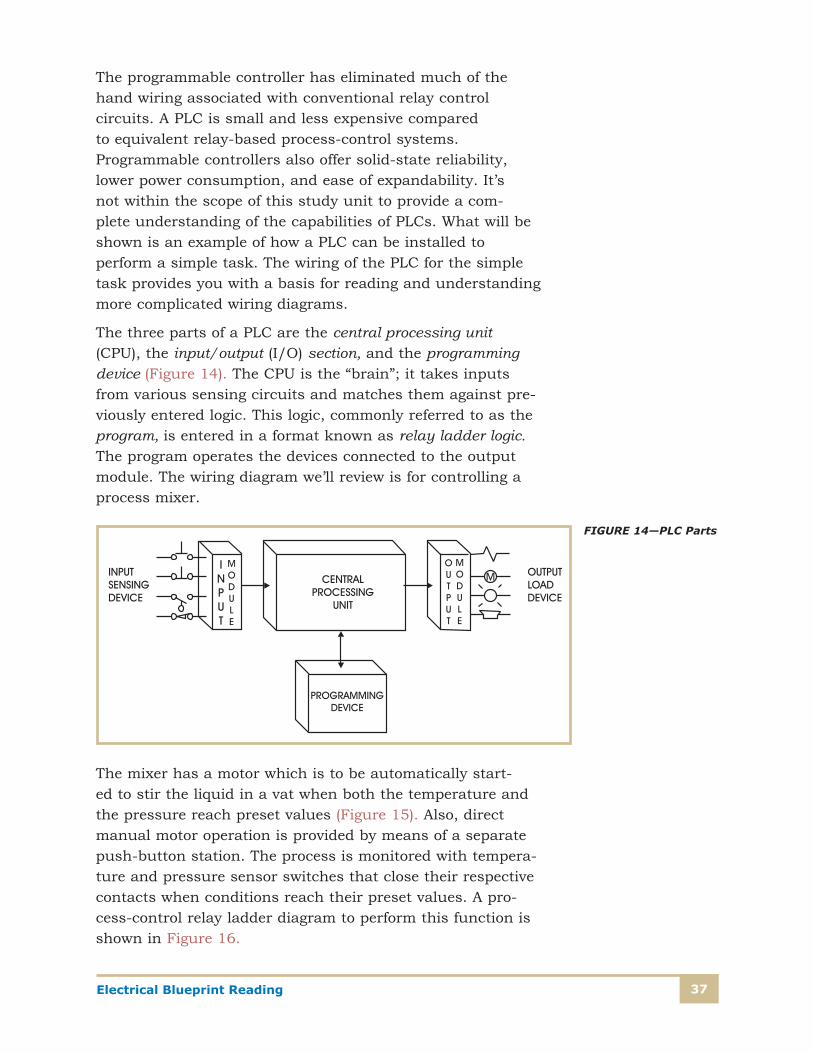
The three parts of a PLC are the central processing unit (CPU), the input/output (I/O) section, and the programming device (Figure 14). The CPU is the “brain”; it takes inputs from various sensing circuits and matches them against pre-viously entered logic. This logic, commonly referred to as the program, is entered in a format known as relay ladder logic. The program operates the devices connected to the output module. The wiring diagram we’ll review is for controlling a process mixer.
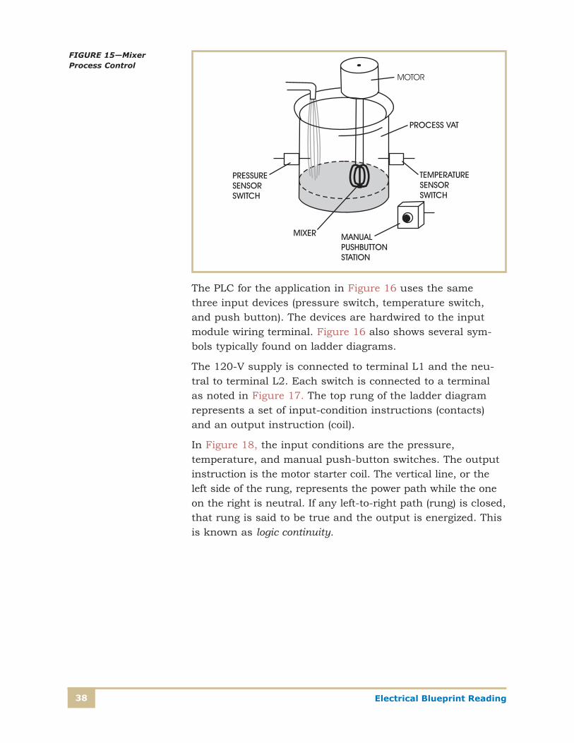
The mixer has a motor which is to be automatically start-ed to stir the liquid in a vat when both the temperature and the pressure reach preset values (Figure 15). Also, direct manual motor operation is provided by means of a separate push-button station. The process is monitored with tempera-ture and pressure sensor switches that close their respective contacts when conditions reach their preset values. A pro-cess-control relay ladder diagram to perform this function is shown in Figure 16.
FIGURE 14—PLC Parts
Electrical Blueprint Reading38
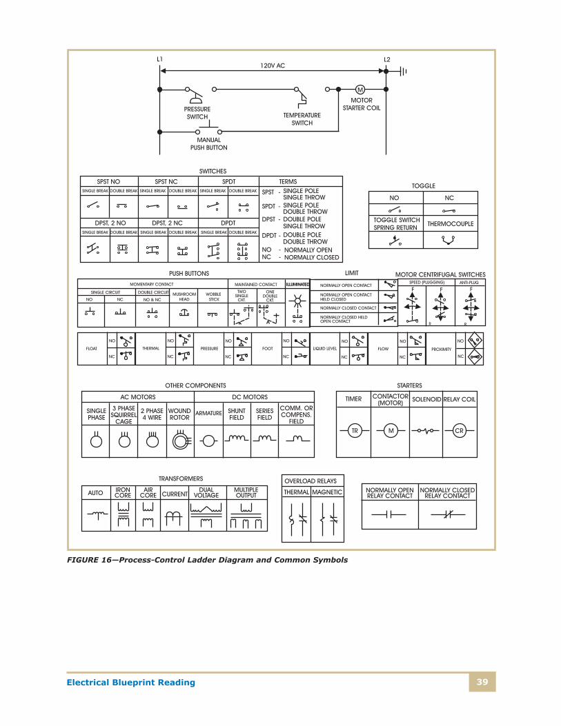
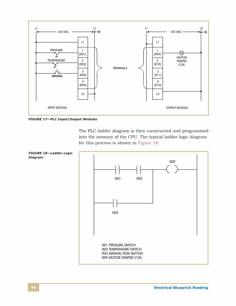
The PLC for the application in Figure 16 uses the same three input devices (pressure switch, temperature switch, and push button). The devices are hardwired to the input module wiring terminal. Figure 16 also shows several sym-bols typically found on ladder diagrams.
The 120-V supply is connected to terminal L1 and the neu-tral to terminal L2. Each switch is connected to a terminal as noted in Figure 17. The top rung of the ladder diagram represents a set of input-condition instructions (contacts) and an output instruction (coil).
In Figure 18, the input conditions are the pressure, temperature, and manual push-button switches. The output instruction is the motor starter coil. The vertical line, or the left side of the rung, represents the power path while the one on the right is neutral. If any left-to-right path (rung) is closed, that rung is said to be true and the output is energized. This is known as logic continuity.
FIGURE 15—Mixer Process Control
39Electrical Blueprint Reading
FIGURE 16—Process-Control Ladder Diagram and Common Symbols
Electrical Blueprint Reading40
The PLC ladder diagram is then constructed and programmed into the memory of the CPU. The typical ladder logic diagram for this process is shown in Figure 18.
FIGURE 17—PLC Input/Output Modules
FIGURE 18—Ladder Logic Diagram

41Electrical Blueprint Reading
The format is similar to the layout of the hardwired relay lad-der circuit. The individual symbols represent instructions, while the numbers represent the instruction addresses. When the controller is programmed, these instructions are entered one by one into the processor memory from the operator’s keyboard. Instructions are stored in the user program portion of the processor memory. For operation of the system, the controller is set in the run mode. During each cycle, the con-troller examines the status of the input devices, executes the user program, and changes the outputs accordingly.
The advantage of the PLC is the ease with which the pro-gram, and thus the operation, can be changed. If the operation is to be changed to allow only the manual push button to operate the mixer if the specified temperature is reached, the only change required is to alter the PLC ladder logic diagram. No change is required in the hardwiring of the various devices. The strength of this flexibility is evident when a large number of inputs and outputs are needed, and a major change in the operating scheme is required.

Electrical Blueprint Reading42
Self-Check 4
1. Why is it important to understand the operation of equipment when you read blueprints?
__________________________________________________________
2. What sources can be used to get an understanding of a specific piece of electrical equipment?
__________________________________________________________
3. Refer to the motor control circuit in Figure 11. Why is there a contact in parallel with the start button?
__________________________________________________________
4. Does the thermostat in the heating circuit in Figure 12 directly make and break the line- voltage supply to the heaters? Why or why not?
__________________________________________________________
5. Do PLCs require completely different input devices and output devices than those used with hardwired control circuits? Explain.
__________________________________________________________
__________________________________________________________
Check your answers with those on page 60.
43Electrical Blueprint Reading
MANUFACTURING FACILITYA complete set of electrical blueprints for an individual facility consists of many drawings. There will be a site plan; electric construction drawings for each floor, generally with a separate lighting drawing and power-supply drawing; a sin-gle-line (one-line) diagram; panel and equipment schedules; clarifying arrangement drawings; fixture lists; and detailed wiring diagrams for specific pieces of equipment. For the pur-pose of this study unit, we’ll refer to selected portions of a variety of drawings for a manufacturing facility. The intent of this unit is to teach you how to read various types of draw-ings, not to familiarize you with the details of everything being installed at the facility.
Site Plan Prior to reading the electrical plans for a building, you should first get an overall understanding of the construction require-ments (size, number of stories, intended usage, construction techniques, and construction materials). With this informa-tion, you’ll have a clearer understanding of the electric facilities needed and how they can be installed. The building in this example is a two-story steel structure, with a base-ment, concrete floors, and finished interior walls. A review of the overall site plan (Plate 2A) shows the footprint of the building, the location of the electric supply into the building, and the exterior lighting equipment.
We’ll concentrate first on the exterior power-supply facilities. A pad-mounted transformer is located at the northwest cor-ner of the building. To indicate the shared responsibilities between the utility company and the electrical contractor at this location, an arrangement detail (Detail A) was provided by the engineer. This detail clarifies the responsibilities of each party. Further, the detail shows the clearance required between the transformer and the building and identifies an area in front of the transformer that must be kept free of any obstructions. This free area is to enable the utility person-nel to install and perform maintenance on the transformer. Examination of the site plan identifies four separate conduit
Electrical Blueprint Reading44
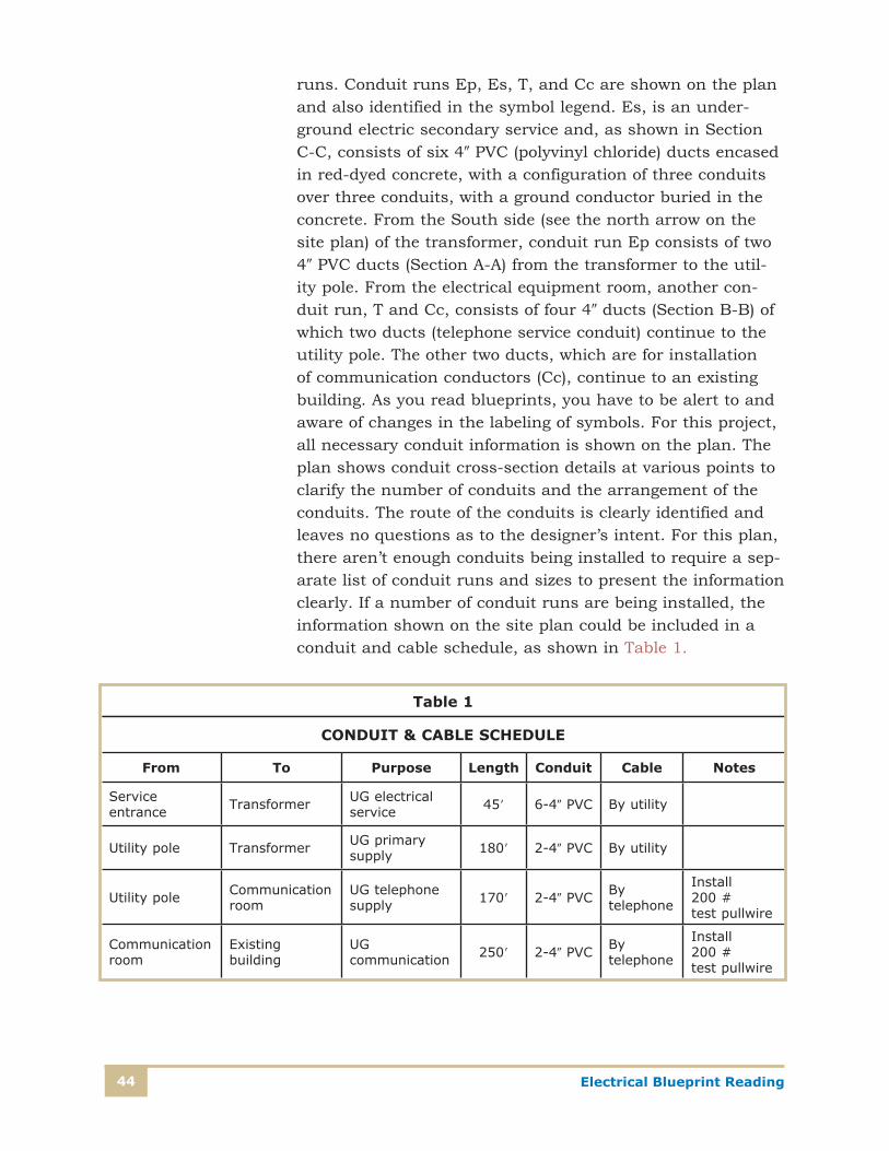
runs. Conduit runs Ep, Es, T, and Cc are shown on the plan and also identified in the symbol legend. Es, is an under-ground electric secondary service and, as shown in Section C-C, consists of six 40 PVC (polyvinyl chloride) ducts encased in red-dyed concrete, with a configuration of three conduits over three conduits, with a ground conductor buried in the concrete. From the South side (see the north arrow on the site plan) of the transformer, conduit run Ep consists of two 40 PVC ducts (Section A-A) from the transformer to the util-ity pole. From the electrical equipment room, another con-duit run, T and Cc, consists of four 40 ducts (Section B-B) of which two ducts (telephone service conduit) continue to the utility pole. The other two ducts, which are for installation of communication conductors (Cc), continue to an existing building. As you read blueprints, you have to be alert to and aware of changes in the labeling of symbols. For this project, all necessary conduit information is shown on the plan. The plan shows conduit cross-section details at various points to clarify the number of conduits and the arrangement of the conduits. The route of the conduits is clearly identified and leaves no questions as to the designer’s intent. For this plan, there aren’t enough conduits being installed to require a sep-arate list of conduit runs and sizes to present the information clearly. If a number of conduit runs are being installed, the information shown on the site plan could be included in a conduit and cable schedule, as shown in Table 1.
Table 1
CONDUIT & CABLE SCHEDULE
From To Purpose Length Conduit Cable Notes
Service entrance Transformer UG electrical
service 459 6-40 PVC By utility
Utility pole Transformer UG primary supply 1809 2-40 PVC By utility
Utility pole Communication room
UG telephone supply 1709 2-40 PVC By
telephone
Install 200 # test pullwire
Communication room
Existing building
UG communication 2509 2-40 PVC By
telephone
Install 200 # test pullwire
45Electrical Blueprint Reading
This schedule shows each run of conduit separately, with from and to locations. The length of conduit, number of con-duits, purpose of the conduit run, and any special notes are included.
Single-Line DiagramPlate 2B shows a single-line diagram for the project. This drawing shows the electrical distribution system from the point of contact with the electric utility through the plant’s switchgear, to the distribution panels, through several step-down transformers, to lighting and power panels located throughout the building. The purpose of the single-line diagram, as mentioned before, is to show the electrical connections and the number and size of conductors, but not the physical location of equipment or conduit runs. Transformation points, junction points, major load centers, and major pieces of equipment are shown on the single-line diagram.
Construction personnel use the single-line diagram for following the planned connections of the facilities they’ll be installing. Operating personnel consult the single-line dia-gram to determine how the equipment is connected as well as the direction of the power feeds. In addition, when a portion of the electric facility is out of service, the electric utility or plant maintenance personnel use the single-line diagram to identify places to sectionalize and isolate the problem area.
The single-line diagram for this facility shows the utility pro-viding a power supply that’s reduced from its primary voltage (12,470/7200 V) to secondary service voltage (480/277 V) at the utility’s transformer. The transformer symbol is shown along with the capacity and the voltage rating. Next, the sin-gle-line diagram shows the metering for the electric utility, the plant’s main disconnect switch, and the power supply branch-ing off to several individual power panels. Additional voltage transformation points for the lighting and small power panels are shown. From these panels, the power supply branches off to individual lighting circuits and other power circuits.
Electrical Blueprint Reading46
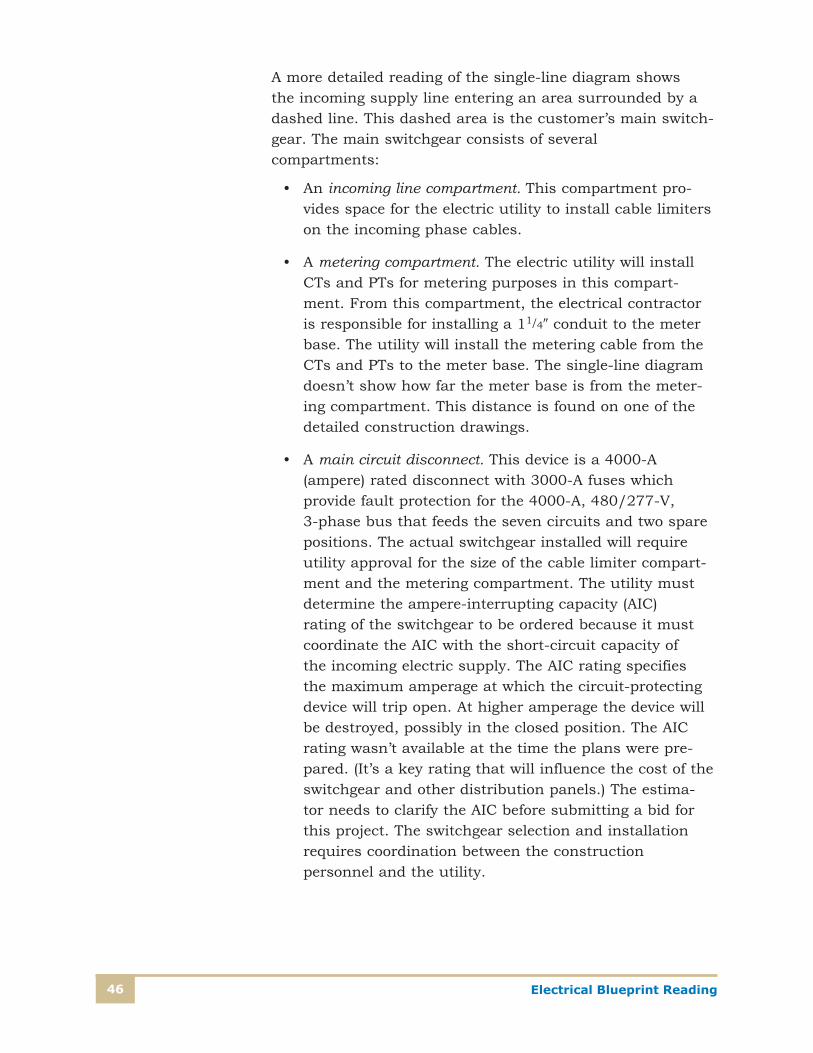
A more detailed reading of the single-line diagram shows the incoming supply line entering an area surrounded by a dashed line. This dashed area is the customer’s main switch-gear. The main switchgear consists of several compartments:
• An incoming line compartment. This compartment pro-vides space for the electric utility to install cable limiters on the incoming phase cables.
• A metering compartment. The electric utility will install CTs and PTs for metering purposes in this compart-ment. From this compartment, the electrical contractor is responsible for installing a 11/40 conduit to the meter base. The utility will install the metering cable from the CTs and PTs to the meter base. The single-line diagram doesn’t show how far the meter base is from the meter-ing compartment. This distance is found on one of the detailed construction drawings.
• A main circuit disconnect. This device is a 4000-A (ampere) rated disconnect with 3000-A fuses which provide fault protection for the 4000-A, 480/277-V, 3-phase bus that feeds the seven circuits and two spare positions. The actual switchgear installed will require utility approval for the size of the cable limiter compart-ment and the metering compartment. The utility must determine the ampere-interrupting capacity (AIC) rating of the switchgear to be ordered because it must coordinate the AIC with the short-circuit capacity of the incoming electric supply. The AIC rating specifies the maximum amperage at which the circuit-protecting device will trip open. At higher amperage the device will be destroyed, possibly in the closed position. The AIC rating wasn’t available at the time the plans were pre-pared. (It’s a key rating that will influence the cost of the switchgear and other distribution panels.) The estima-tor needs to clarify the AIC before submitting a bid for this project. The switchgear selection and installation requires coordination between the construction personnel and the utility.
47Electrical Blueprint Reading
• Feeder compartments. Each circuit feeder position shows a switch and appropriate fusing size matched to the size of the feeder conductors. The fuses protect the feeder and the panel connected to the feeder. Later, when you read one of the panel schedules, you’ll see that the pan-els are “Lugs Only,” that is, no switch or fuse is provided at the panel.
The single-line diagram shows the conductors and conduit between the switchgear and each individual panel. What isn’t shown is the length or the physical path of the feeders through the building. The single-line diagram shows four #4/0 and one #4G conductors in a 21/20 CND (conduit) as the feed for panel PP1. The four #4/0 (copper) wires consist of three phase conductors and one neutral conductor; the one #4 G wire is the ground conductor. (A general note on the drawing states that all conductors are copper unless desig-nated otherwise.) The phase conductors will be energized at 480 V measured phase to phase, or 277 V measured phase conductor to neutral. The 225-A fuses provide the fault pro-tection for each of the energized conductors.
From the main switchgear to panel LPB, two sets of conduc-tors (4-#350 MCM and 1-#1/0 G) and 30 CNDs are installed. This notation means that two sets of conductors are to be installed. Each set will be in its own 30 conduit. The conduc-tors will be paralleled to provide the required ampere capacity for the load connected to panel LPB. The main switchgear directly feeds a motor power panel (MP2) providing 480/277-V circuits, five power panels (PP1 through PP5)—which also provide 480/277-V circuits—and a lighting power panel (LPB) in the basement. The LPB panel (480/277 V) supplies two 3-phase 480/277-V lighting panels (LP1 and LP2) and two transformers (T1 and T2). Transformer T1 is rated at 225 kVA with a 480-V D (Greek letter delta) primary connection and a secondary voltage of 208/120 VY (wye) connection. This transformer steps down the 480/277-V voltage to the 208/120-V utilization voltage and supplies power to five other panels (one in the basement and two each on the first and second floors). The transformer T2 is rated 30 kVA and steps down the 480/277-V supply (D connection) to 230 D for supplying some motor load located on the first floor.
Electrical Blueprint Reading48
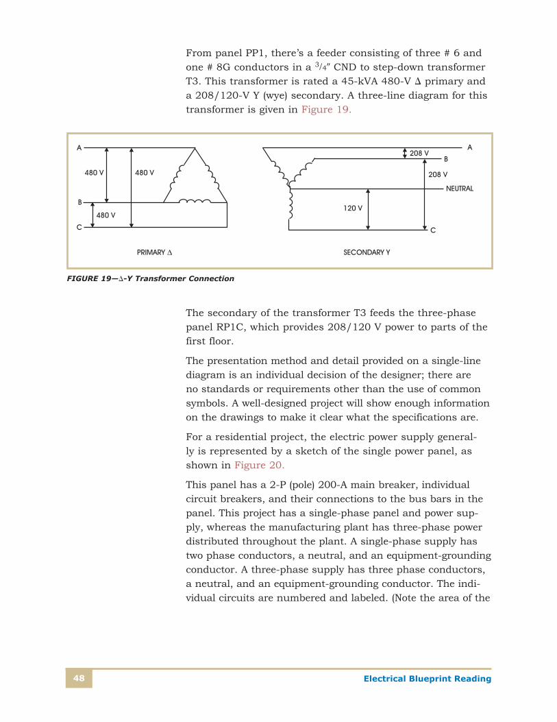
From panel PP1, there’s a feeder consisting of three # 6 and one # 8G conductors in a 3/40 CND to step-down transformer T3. This transformer is rated a 45-kVA 480-V D primary and a 208/120-V Y (wye) secondary. A three-line diagram for this transformer is given in Figure 19.
The secondary of the transformer T3 feeds the three-phase panel RP1C, which provides 208/120 V power to parts of the first floor.
The presentation method and detail provided on a single-line diagram is an individual decision of the designer; there are no standards or requirements other than the use of common symbols. A well-designed project will show enough information on the drawings to make it clear what the specifications are.
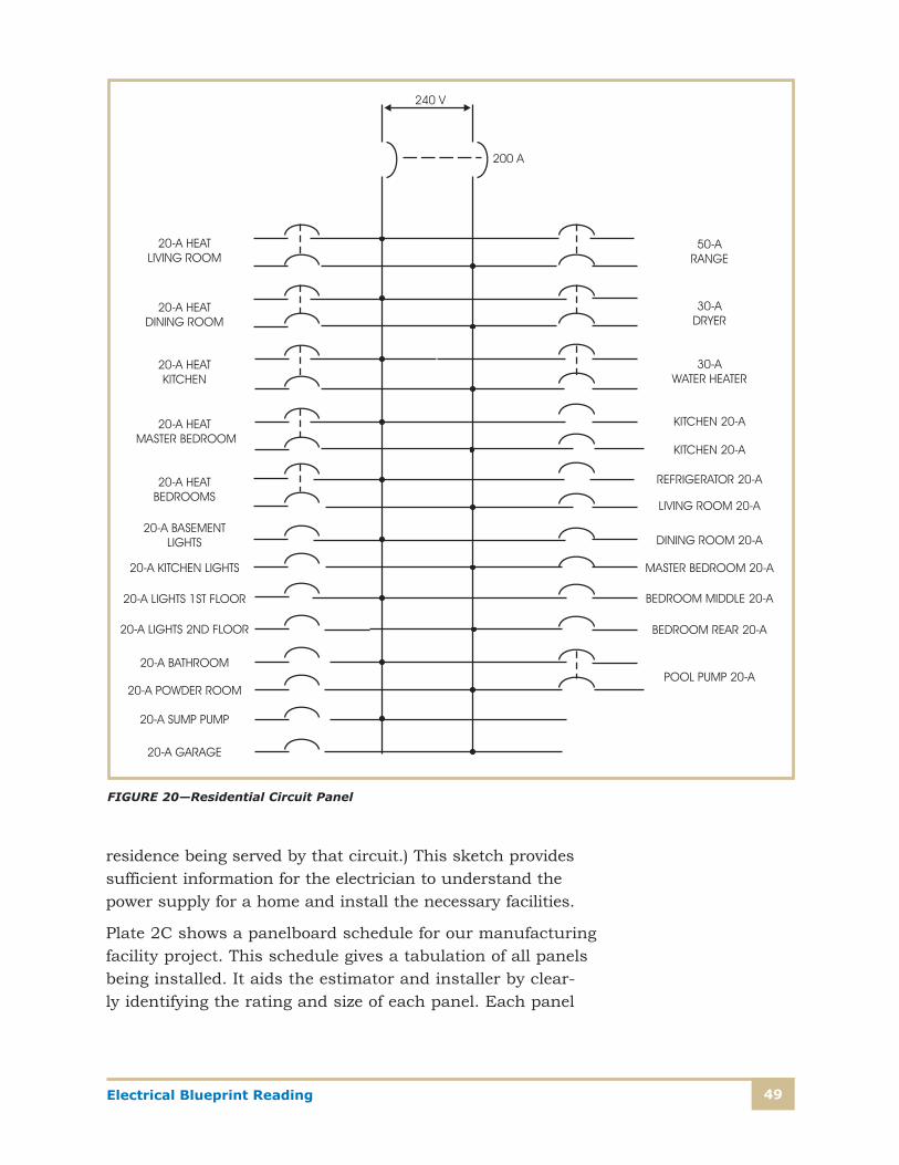
For a residential project, the electric power supply general-ly is represented by a sketch of the single power panel, as shown in Figure 20.
This panel has a 2-P (pole) 200-A main breaker, individual circuit breakers, and their connections to the bus bars in the panel. This project has a single-phase panel and power sup-ply, whereas the manufacturing plant has three-phase power distributed throughout the plant. A single-phase supply has two phase conductors, a neutral, and an equipment-grounding conductor. A three-phase supply has three phase conductors, a neutral, and an equipment-grounding conductor. The indi-vidual circuits are numbered and labeled. (Note the area of the
FIGURE 19—D-Y Transformer Connection
49Electrical Blueprint Reading
residence being served by that circuit.) This sketch provides sufficient information for the electrician to understand the power supply for a home and install the necessary facilities.
Plate 2C shows a panelboard schedule for our manufacturing facility project. This schedule gives a tabulation of all panels being installed. It aids the estimator and installer by clear-ly identifying the rating and size of each panel. Each panel
FIGURE 20—Residential Circuit Panel
Electrical Blueprint Reading50
is listed, with its name or designation, its physical location, the size of the wires providing the feed to the panel, the size of the mains, and the branch-circuit information. Looking at panel PP1, you see that the location is first-floor rear, and the power feed is four #4/0 and one #4 G wires, as you saw on the single-line diagram. The voltage of this panel is the same voltage as the main service, that is, 480/277 V. The rating of the panel and its bus bars is 225 A. The panel is to have 42 spaces for individual circuits. By examining the more detailed schedule that specifically addresses panel PP1, you can see that circuits from the panel include
• Two 3-P (three-pole) circuits with circuit breakers rated 70 A and 15 A
• Nine 2-P (two-pole) circuits with circuit breakers rated 25 A and 30 A, with the actual number of each needed taken from the individual panel schedule
• Five S-P (single-pole) circuits, all with 20-A circuit breakers and 13 spare positions for future load
Normally, similar information is provided for each of the pan-els in the plant. In this example, we’ve only provided detailed panel schedules for three panels.
A separate schedule is provided for three of the panels being installed. Plate 2C also shows the schedule for panel PP1. Some of the same information previously provided is listed, but the schedule shows each individual circuit. For each circuit, the breaker rating is shown; for instance, circuit 1 shows a 2-P 25-A circuit breaker for the sewing floor lighting. Circuit 1 connects to positions 1 and 3 in the panel, tapping two of the three phases. The actual estimated load for circuit 1 on each phase conductor is 3.89 A. The total load connected to phase A at positions 1 and 2 is 7.78 A, the sum of the phase A load from circuits 1 and 2. Circuit 21 is a single-phase circuit. A 1-P 20-A breaker protects the 277-V lighting supply to rooms 120, 122, and the loading dock. Circuit 23, 25, 27 is a three-phase circuit, and a 3-P 15-A circuit breaker supplies and provides circuit protec-tion for the loading dock leveler. Circuit 26,28,30 also is a three-phase circuit, and a 3-P 70-A circuit breaker supplies and protects the T3 transformer, which supplies the office
51Electrical Blueprint Reading
area lighting panel. The schedule tabulates the load for each phase conductor and provides circuit load totals and phase load totals at the bottom of the schedule. This enables the designer to balance the load between the phases and to document the expected load information for the installer. The complete set of construction drawings for this project would show a schedule for each panel and identify all the circuits throughout the plant.
Lighting and Receptacle PlanBefore the lighting and power plans are prepared, a decision is made on the general type of electrical distribution system for a facility. The characteristics and voltage of the branch circuits are then determined. Plate 2D is a representative portion of the lighting plan for the facility we’re discuss-ing. The designer used this detailed information to size the individual panel, feeders, and service. For this facility, the designer decided on a main service voltage of 480/277 V after a preliminary assessment of the expected electric load and approval from the local utility. This voltage level provides a robust power supply and has minimal voltage drop through-out the facility. The engineer then designed a lighting system that utilizes the 277-V (phase-to-neutral) supply. As you’ll see, this supply choice keeps the number of lighting circuits to a minimum. Switching can still be done with S-P toggle switches, rated for 277-V lighting.
The design engineer determined the actual lighting levels required based on the tasks being performed in the various areas. From the lighting level required and the tasks being performed, the lighting engineer determined the actual num-ber and types of light fixtures. The engineer located where fixtures should be installed, calculated the load, determined the number of circuits required, and selected the type of switching for the light fixtures. All this information was used to prepare the lighting plans. The designer adds the lighting fixture and supply details to the general architectural floor plan, creating the lighting plan. These lighting plans are used by the estimator to cost out the project and by the electrical contractor to install the circuits and fixtures throughout the facility.

Electrical Blueprint Reading52
The commonly used lighting plan symbols, along with the job-specific symbol legend and the light fixture schedule or bill of material, provide the information to understand the lighting plan. Let’s trace the supply for the light fixtures in the storage area, starting with the light fixtures and ending with a connection to the lighting panel. Refer to the Lighting Plan on Plate 2D, the Light Fixture Schedule (found on Plate 2C), and the symbol legend (found on Plate 2C).
In the storage area, at the top right of Plate 2D, you see a symbol that represents a fluorescent light fixture. The ´A´ in the symbol refers to the type of fixture, which is defined in the Fixture Schedule. Fixture ´A´ is a Lithonia lighting fixture, Catalog Number AFST-2-32-277GEBIO, Industrial fixture rapid start, and contains two fluorescent lamps, Catalog Number F32T8/TL830. The fixture operates at 277 V, with a 277-V ballast, and is suitable for installations in indoor environments. The feed for the light fixtures in the storage area is based on the branch circuit symbols on the job symbol legend. The feed consists of three #12 conduc-tors with one phase conductor, one neutral, and the third a grounding conductor having a green covering. All of the con-ductors are installed in a single 3/40 conduit, as indicated in the symbol legend of Plate 2C. The conduit is to be installed in the ceiling area and the run of conduit is to be exposed. The 12 light fixtures in the storage area are to be controlled by a S-P switch rated 20 A 120/277 V. The switch is speci-fied to be mounted 49-00 above the finished floor (AFF). The switch rating and mounting-height information is given the symbol legend of Plate 2C.
As you trace the conduit run, you see that the portion of the conduit (still 3/40 with three #12 conductors) in the lunch area is concealed. In this area, the ceiling will be finished and the conduit will be above the finished ceiling. In the lunch area, the branch-circuit symbol identifies that four conductors are in the conduit. (See Legend.) The four conductors consist of two phase conductors, one neutral conductor (denoted by the longer hatch mark), and one grounding conductor (the longer hatch mark with the dot at the end of the hatch). An addi-tional feed (consisting of three conductors) begins at the ´B´ fixture closest to the doorway from the storage room to the lunch room and extends to the two light fixtures ´E´, with an
53Electrical Blueprint Reading
associated switch over some counters. The circuit feed con-tinues back to fixtures ´K´ and then to LPB3 (Lighting Panel Basement circuit 3). The plans show the electrical connection of the lights, but it’s up to the installer to plan the physical routing of the circuits. The installer makes this decision at the job site based on the actual physical conditions.
The other circuits from the light panel can be traced, either from the most distant point, as you did with the above light-ing circuit or from the point on the plans where a “home run” to the panel is shown. The circuits aren’t shown physically connected to the panel; they’re pointed back to the panel with the circuit number noted. This method is used to avoid clut-ter on the drawings.
The lighting plan also includes the wiring for one of the ancillary systems installed by the electrical contractor. The construction details of the emergency lighting system are shown. There’s an unswitched hot lead feeding an emergen-cy lighting unit labeled “J” located at the corner of the lunch area. This unit contains a battery that’s continually main-tained in a charged state by an internal charging unit. From this unit, a DC (direct-current) feed goes to a two-head light unit “M” in the lobby. When the unswitched hot conductor goes dead, the batteries energize the light heads located on this unit, the two-head light unit, and the exit lights. This emergency operation occurs if power is interrupted to the building. Note 1 for the drawing calls for the unswitched hot conductor.
Power and Signal PlanThe power and signal plan shows the construction details for the general- use receptacles, the motors to be installed, if any, and an alarm signal system. An examination of Plate 2E shows that many of the receptacles have dedicated use and are sep-arate circuits, fed directly from panel RPB. Referring to the panel schedule on Plate 2C, you see that RPB is a three-phase 208/120-V panel. All loads connected to RPB either have to operate at 120 V phase to neutral or 208 V phase to phase. Standard convenience receptacles and fractional-horsepower motors operate at 120 V. Large motors are more efficient at the higher voltage of 208 V.
Electrical Blueprint Reading54
Again, if you start in the lunch area on Plate 2E, you see many individual receptacles shown with the home run sym-bol. The symbol shows thedirected arrow along with the panel name and a circuit number. In the lunch area, there are three duplex receptacles, and three single-outlet recepta-cles to be installed, each with a separate circuit connection. On the left side of the counter, a GFCI receptacle is mount-ed at counter height, fed from RPB-5, from which the feed also picks up a receptacle in the storage area, another GFCI receptacle on the left side of the lunch area, and a transform-er. The transformer is supplied by the plumbing contractor and is to be installed by the electrical contractor. From this transformer, a 1/20 conduit with three #16 wires going to three 2-gang boxes in the men’s restroom is to be installed by the electrical contractor. These wires are for the automatic flushing system (AFS) installed in the men’s restroom. The AFS uses infrared sensors for automatic operation of the flushing valve.
Where there are several receptacles connected on the same circuit, the receptacles are linked together with the branch circuit symbol similar to what we have seen with the light-ing circuit. Most of the receptacles have a symbol connecting them, which denotes a concealed 3/40 conduit with three #12 conductors: one conductor is a phase conductor; the sec-ond, a neutral; and the third, a ground—a conductor with green-colored insulation.
Let’s look at the mechanical room and the equipment located there as detailed on the power plan. There’s a gener-al-purpose receptacle that’s part of circuit RPB-1. The feed comes from a receptacle in the corridor and continues on to the men’s lockers and beyond, picking up an additional three receptacles. The mechanical room contains the following equipment and connections:
• ATC panel. A dedicated circuit RPB-32 feeds this control panel.
• Modular boilers. Two boilers each have a switch for the power supply coming from a junction box, fed by circuit RPB-30.
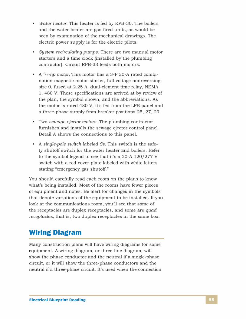
55Electrical Blueprint Reading
• Water heater. This heater is fed by RPB-30. The boilers and the water heater are gas-fired units, as would be seen by examination of the mechanical drawings. The electric power supply is for the electric pilots.
• System recirculating pumps. There are two manual motor starters and a time clock (installed by the plumbing contractor). Circuit RPB-33 feeds both motors.
• A 3/4-hp motor. This motor has a 3-P 30-A rated combi-nation magnetic motor starter, full voltage nonreversing, size 0, fused at 2.25 A, dual-element time relay, NEMA 1, 480 V. These specifications are arrived at by review of the plan, the symbol shown, and the abbreviations. As the motor is rated 480 V, it’s fed from the LPB panel and a three-phase supply from breaker positions 25, 27, 29.
• Two sewage ejector motors. The plumbing contractor furnishes and installs the sewage ejector control panel. Detail A shows the connections to this panel.
• A single-pole switch labeled Ss. This switch is the safe-ty shutoff switch for the water heater and boilers. Refer to the symbol legend to see that it’s a 20-A 120/277 V switch with a red cover plate labeled with white letters stating “emergency gas shutoff.”
You should carefully read each room on the plans to know what’s being installed. Most of the rooms have fewer pieces of equipment and notes. Be alert for changes in the symbols that denote variations of the equipment to be installed. If you look at the communications room, you’ll see that some of the receptacles are duplex receptacles, and some are quad receptacles, that is, two duplex receptacles in the same box.
Wiring DiagramMany construction plans will have wiring diagrams for some equipment. A wiring diagram, or three-line diagram, will show the phase conductor and the neutral if a single-phase circuit, or it will show the three-phase conductors and the neutral if a three-phase circuit. It’s used when the connection

Electrical Blueprint Reading56
of individual conductors to individual components is import-ant. Each individual conductor and the connection of each conductor are shown.
Referring again to the site plan (Plate 2A), you see that the outdoor lighting electric supply comes from panel PP1. The control of the lighting for the flagpole and a walkway is via a time clock and a photocell. The wiring diagram given on Plate 2A shows a detail of how this equipment is to be con-nected. Also, Details C and D show how the control circuit is to be connected. Both the phase conductor (LINE) and the neutral are shown. The connections of the phase conductor are important to ensure that the lights work properly on both the time clock and the photocell. The photoelectric cell oper-ates on the light level it senses. During daylight hours, it’s an open circuit; that is, it’s in the OFF position. When it can’t sense daylight (nighttime), it closes and stays closed until it senses daylight again. The time clock has mechanical on and off trippers that are set to correspond to the plant’s operat-ing hours. When the time clock trips on, the contact for the walkway lights is energized. Providing the photocell is also in an ON position (dark outside), the lights will be turned on. If the photocell is off, the walkway lights stay off, even if the time clock is tripped on. If the time clock circuit is on and the photocell goes to the ON position, the walkway lights, the front entrance lights, and the flagpole light come on. When the time clock trips off, the walkway lights go off, but since the front entrance lights and the flagpole light aren’t connected through a set of contacts with the time clock, they stay on until the photocell operates to the OFF position (sufficient daylight sensed). The manual bypass switch is in shunt with the photocell and allows an operator to bypass the photocell operation.
To ensure the correct installation, the engineer provided the detailed wiring diagram to identify how the various compo-nents need to be connected for correct operation.

57Electrical Blueprint Reading
We’ve examined only a part of the plans for a manufacturing facility. Plans for other types of facilities are similar, varying only in the number and type of individual devices and equip-ment installed. Reading the plans requires an understanding of symbols, the equipment, and the ability to systematically trace each individual item and component. As you gain experience, you’ll be able to quickly identify the items com-mon to different facilities and the variations of equipment installations.

Electrical Blueprint Reading58
Self-Check 5
Refer to Plates 2A through 2E to answer the following questions.
1. On the single-line diagram for the manufacturing facility, what conductors are feeding panel PP5?
__________________________________________________________
2. Refer to the panelboard schedule for panel PP1. What type and rating of breaker and voltage does circuit 22 have?
__________________________________________________________
3. What panels in the manufacturing plant have a voltage supply of 120/208 V?
__________________________________________________________
4. (a) According to the power plan for the basement, how many receptacles are connected to circuit RPB-25?
__________________________________________________________
(b) What is the circuit breaker rating?
__________________________________________________________
5. What is the ampere capacity and voltage of panel RPB?
__________________________________________________________
6. What size breaker protects transformer T3?
__________________________________________________________
7. How are the J fixture units turned on and off?
__________________________________________________________
Check your answers with those on page 60.

An
sw
er
sA
ns
we
rs
59
Self-Check 1
1. The original drawing is expensive to prepare and it wouldn’t last if used for construction purposes. Also, many people require use of the drawing.
2. The architectural drawings are used as a base to which are added the electric devices and components to pro-duce the electrical blueprints.
3. Drawings were originally done in pencil, and then a copy was made in ink from which other copies were made. Later, they were prepared with pencil on tracing paper and copies made. Today, most firms use computer pro-grams and computer plotters to make the drawings.
4. (a) The plan view, front view, and side view generally provide enough detail to understand what the facilities should look like.
(b) At times, additional views are needed because of detail and items being hidden in each of the three views.
5. A schematic shows only the electrical connections. It isn’t drawn to scale and doesn’t contain dimensions.
Self-Check 2
1. False
2. False
3. True
4. False
5. A one-line diagram is a schematic showing only one line, even if there are three-phase conductors. A three-line diagram shows all three phases and additional details on the connections.
Self-Check 3
1. False
2. False
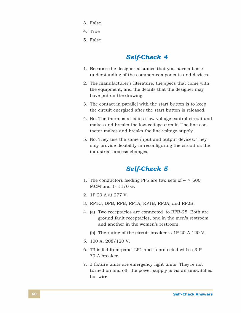
Self-Check Answers60
3. False
4. True
5. False
Self-Check 4
1. Because the designer assumes that you have a basic understanding of the common components and devices.
2. The manufacturer’s literature, the specs that come with the equipment, and the details that the designer may have put on the drawing.
3. The contact in parallel with the start button is to keep the circuit energized after the start button is released.
4. No. The thermostat is in a low-voltage control circuit and makes and breaks the low-voltage circuit. The line con-tactor makes and breaks the line-voltage supply.
5. No. They use the same input and output devices. They only provide flexibility in reconfiguring the circuit as the industrial process changes.
Self-Check 5
1. The conductors feeding PP5 are two sets of 4 3 500 MCM and 1- #1/0 G.
2. 1P 20 A at 277 V.
3. RP1C, DPB, RPB, RP1A, RP1B, RP2A, and RP2B.
4 (a) Two receptacles are connected to RPB-25. Both are ground fault receptacles, one in the men’s restroom and another in the women’s restroom.
(b) The rating of the circuit breaker is 1P 20 A 120 V.
5. 100 A, 208/120 V.
6. T3 is fed from panel LP1 and is protected with a 3-P 70-A breaker.
7. J fixture units are emergency light units. They’re not turned on and off; the power supply is via an unswitched hot wire.
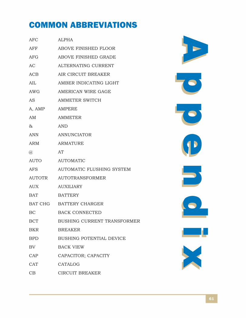
Ap
pe
nd
ix
61
Ap
pe
nd
ixCOMMON ABBREVIATIONSAFC ALPHA
AFF ABOVE FINISHED FLOOR
AFG ABOVE FINISHED GRADE
AC ALTERNATING CURRENT
ACB AIR CIRCUIT BREAKER
AIL AMBER INDICATING LIGHT
AWG AMERICAN WIRE GAGE
AS AMMETER SWITCH
A, AMP AMPERE
AM AMMETER
& AND
ANN ANNUNCIATOR
ARM ARMATURE
@ AT
AUTO AUTOMATIC
AFS AUTOMATIC FLUSHING SYSTEM
AUTOTR AUTOTRANSFORMER
AUX AUXILIARY
BAT BATTERY
BAT CHG BATTERY CHARGER
BC BACK CONNECTED
BCT BUSHING CURRENT TRANSFORMER
BKR BREAKER
BPD BUSHING POTENTIAL DEVICE
BV BACK VIEW
CAP CAPACITOR; CAPACITY
CAT CATALOG
CB CIRCUIT BREAKER
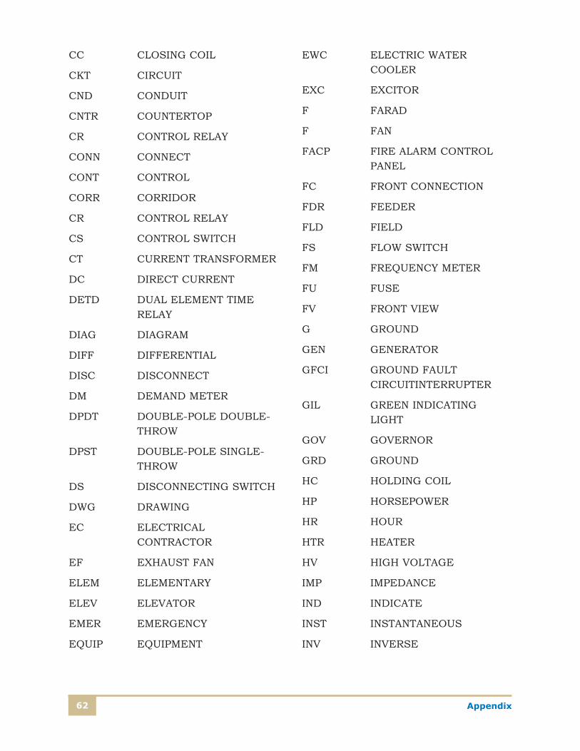
Appendix62
CC CLOSING COIL
CKT CIRCUIT
CND CONDUIT
CNTR COUNTERTOP
CR CONTROL RELAY
CONN CONNECT
CONT CONTROL
CORR CORRIDOR
CR CONTROL RELAY
CS CONTROL SWITCH
CT CURRENT TRANSFORMER
DC DIRECT CURRENT
DETD DUAL ELEMENT TIME RELAY
DIAG DIAGRAM
DIFF DIFFERENTIAL
DISC DISCONNECT
DM DEMAND METER
DPDT DOUBLE-POLE DOUBLE-THROW
DPST DOUBLE-POLE SINGLE-THROW
DS DISCONNECTING SWITCH
DWG DRAWING
EC ELECTRICAL CONTRACTOR
EF EXHAUST FAN
ELEM ELEMENTARY
ELEV ELEVATOR
EMER EMERGENCY
EQUIP EQUIPMENT
EWC ELECTRIC WATER COOLER
EXC EXCITOR
F FARAD
F FAN
FACP FIRE ALARM CONTROL PANEL
FC FRONT CONNECTION
FDR FEEDER
FLD FIELD
FS FLOW SWITCH
FM FREQUENCY METER
FU FUSE
FV FRONT VIEW
G GROUND
GEN GENERATOR
GFCI GROUND FAULT CIRCUITINTERRUPTER
GIL GREEN INDICATING LIGHT
GOV GOVERNOR
GRD GROUND
HC HOLDING COIL
HP HORSEPOWER
HR HOUR
HTR HEATER
HV HIGH VOLTAGE
IMP IMPEDANCE
IND INDICATE
INST INSTANTANEOUS
INV INVERSE
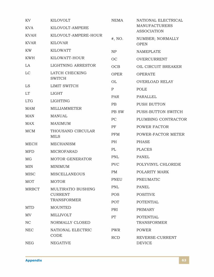
63Appendix
KV KILOVOLT
KVA KILOVOLT-AMPERE
KVAH KILOVOLT-AMPERE-HOUR
KVAR KILOVAR
KW KILOWATT
KWH KILOWATT-HOUR
LA LIGHTNING ARRESTOR
LC LATCH CHECKING SWITCH
LS LIMIT SWITCH
LT LIGHT
LTG LIGHTING
MAM MILLIAMMETER
MAN MANUAL
MAX MAXIMUM
MCM THOUSAND CIRCULAR MILS
MECH MECHANISM
MFD MICROFARAD
MG MOTOR GENERATOR
MIN MINIMUM
MISC MISCELLANEOUS
MOT MOTOR
MRBCT MULTIRATIO BUSHING CURRENT TRANSFORMER
MTD MOUNTED
MV MILLIVOLT
NC NORMALLY CLOSED
NEC NATIONAL ELECTRIC CODE
NEG NEGATIVE
NEMA NATIONAL ELECTRICAL MANUFACTURERS ASSOCIATION
#, NO. NUMBER; NORMALLY OPEN
NP NAMEPLATE
OC OVERCURRENT
OCB OIL CIRCUIT BREAKER
OPER OPERATE
OL OVERLOAD RELAY
P POLE
PAR PARALLEL
PB PUSH BUTTON
PB SW PUSH-BUTTON SWITCH
PC PLUMBING CONTRACTOR
PF POWER FACTOR
PFM POWER-FACTOR METER
PH PHASE
PL PLACES
PNL PANEL
PVC POLYVINYL CHLORIDE
PM POLARITY MARK
PNEU PNEUMATIC
PNL PANEL
POS POSITIVE
POT POTENTIAL
PRI PRIMARY
PT POTENTIAL TRANSFORMER
PWR POWER
RCD REVERSE-CURRENT DEVICE
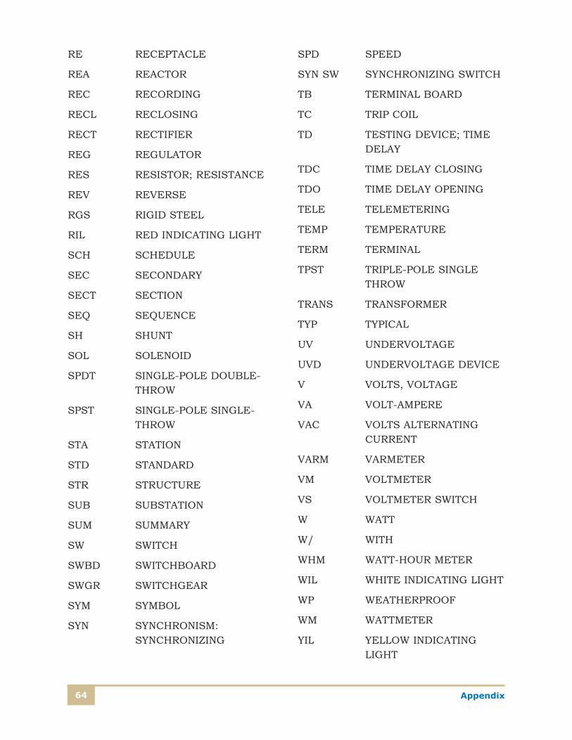
Appendix64
RE RECEPTACLE
REA REACTOR
REC RECORDING
RECL RECLOSING
RECT RECTIFIER
REG REGULATOR
RES RESISTOR; RESISTANCE
REV REVERSE
RGS RIGID STEEL
RIL RED INDICATING LIGHT
SCH SCHEDULE
SEC SECONDARY
SECT SECTION
SEQ SEQUENCE
SH SHUNT
SOL SOLENOID
SPDT SINGLE-POLE DOUBLE-THROW
SPST SINGLE-POLE SINGLE-THROW
STA STATION
STD STANDARD
STR STRUCTURE
SUB SUBSTATION
SUM SUMMARY
SW SWITCH
SWBD SWITCHBOARD
SWGR SWITCHGEAR
SYM SYMBOL
SYN SYNCHRONISM: SYNCHRONIZING
SPD SPEED
SYN SW SYNCHRONIZING SWITCH
TB TERMINAL BOARD
TC TRIP COIL
TD TESTING DEVICE; TIME DELAY
TDC TIME DELAY CLOSING
TDO TIME DELAY OPENING
TELE TELEMETERING
TEMP TEMPERATURE
TERM TERMINAL
TPST TRIPLE-POLE SINGLE THROW
TRANS TRANSFORMER
TYP TYPICAL
UV UNDERVOLTAGE
UVD UNDERVOLTAGE DEVICE
V VOLTS, VOLTAGE
VA VOLT-AMPERE
VAC VOLTS ALTERNATING CURRENT
VARM VARMETER
VM VOLTMETER
VS VOLTMETER SWITCH
W WATT
W/ WITH
WHM WATT-HOUR METER
WIL WHITE INDICATING LIGHT
WP WEATHERPROOF
WM WATTMETER
YIL YELLOW INDICATING LIGHT
Ex
am
ina
tion
Ex
am
ina
tion
65
1. How many receptacles are connected to circuit 24 from panel RPB in the manufacturing facility? Use the series of plates supplied with this study unit.
A. 1 C. 4B. 3 D. 8
2. What is the meaning of the symbol S3?
A. Three single-pole switchesB. One three-way switchC. A triple-pole switch D. A single switch mounted at 39-00
3. For the manufacturing facility, what conductors connect panel PP2 to the main power supply?Use the series of plates sup-plied with this study unit.
A. 8 conductors #500,000 circular mil size and 2-#1/0 size ground conductors
B. 4-#4/0 size conductors and 1-#4 size ground conductorC. 8 conductors #500,000 circular mil size and 1-#1/0 size
ground conductorD. 3 conductors #600,000 circular mil size and 1-#2 size
ground conductor
Electrical Blueprint Reading
When you feel confident that you have mastered the material in this study unit, go to http://www.pennfoster.edu and submit your answers online. If you don’t have access to the Internet, you can phone in or mail in your exam. Submit your answers for this examination as soon as you complete it. Do not wait until another examination is ready.
Questions 1–20: Select the one best answer to each question.
EXAMINATION NUMBER
00603601Whichever method you use in submitting your exam
answers to the school, you must use the number above
For the quickest test results, go tohttp://www.pennfoster.edu
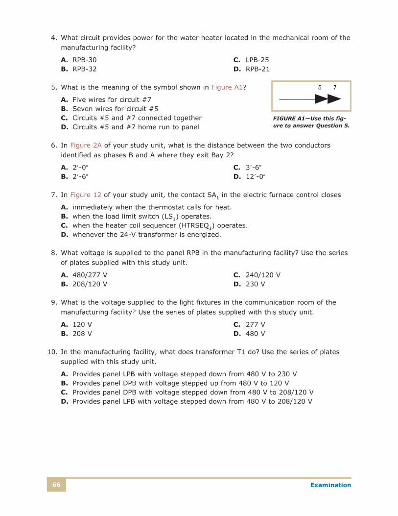
Examination66
4. What circuit provides power for the water heater located in the mechanical room of the manufacturing facility?
A. RPB-30 C. LPB-25B. RPB-32 D. RPB-21
5. What is the meaning of the symbol shown in Figure A1?
A. Five wires for circuit #7B. Seven wires for circuit #5C. Circuits #5 and #7 connected togetherD. Circuits #5 and #7 home run to panel
6. In Figure 2A of your study unit, what is the distance between the two conductors identified as phases B and A where they exit Bay 2?
A. 29-00 C. 39-60
B. 29-60 D. 129-00
7. In Figure 12 of your study unit, the contact SA1 in the electric furnace control closes
A. immediately when the thermostat calls for heat.B. when the load limit switch (LS1) operates.C. when the heater coil sequencer (HTRSEQ1) operates.D. whenever the 24-V transformer is energized.
8. What voltage is supplied to the panel RPB in the manufacturing facility? Use the series of plates supplied with this study unit.
A. 480/277 V C. 240/120 VB. 208/120 V D. 230 V
9. What is the voltage supplied to the light fixtures in the communication room of the manufacturing facility? Use the series of plates supplied with this study unit.
A. 120 V C. 277 VB. 208 V D. 480 V
10. In the manufacturing facility, what does transformer T1 do? Use the series of plates supplied with this study unit.
A. Provides panel LPB with voltage stepped down from 480 V to 230 VB. Provides panel DPB with voltage stepped up from 480 V to 120 VC. Provides panel DPB with voltage stepped down from 480 V to 208/120 VD. Provides panel LPB with voltage stepped down from 480 V to 208/120 V
FIGURE A1—Use this fig-ure to answer Question 5.
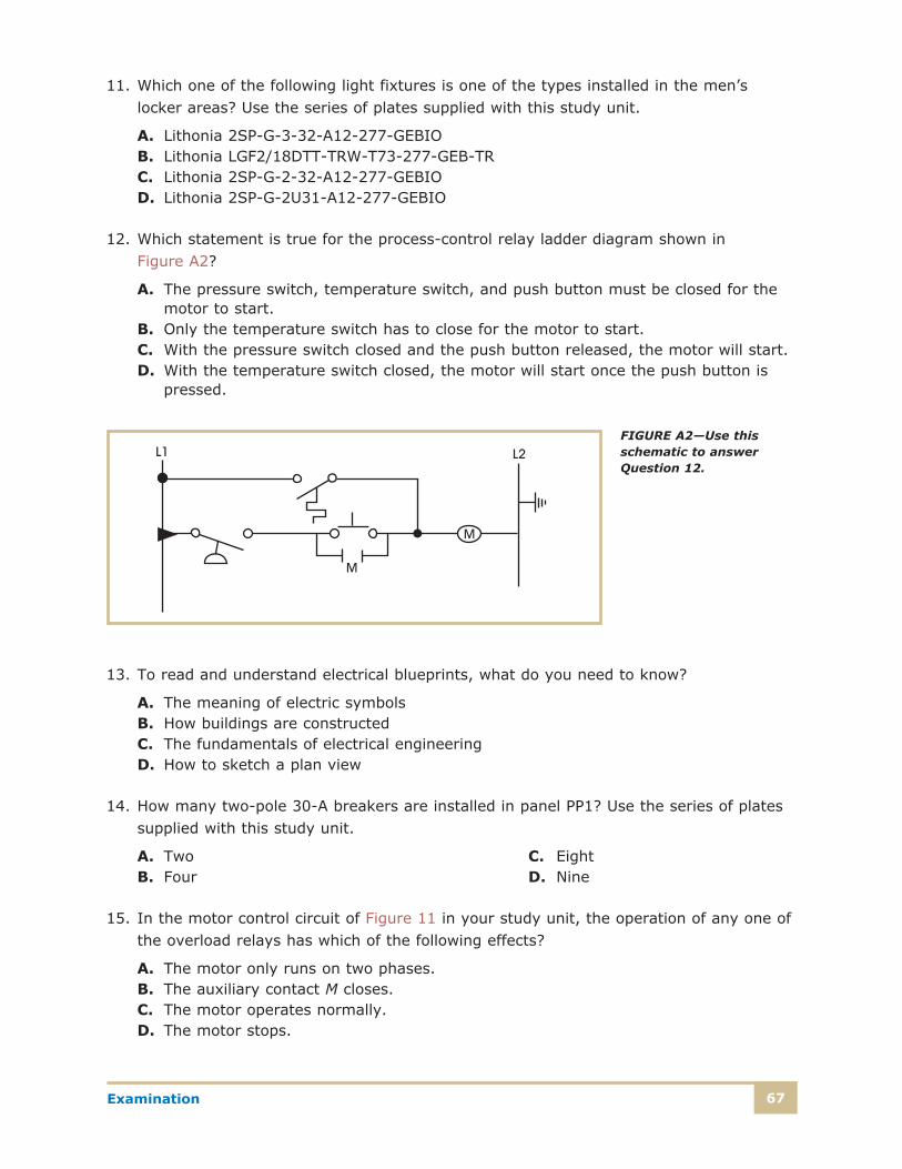
67Examination
11. Which one of the following light fixtures is one of the types installed in the men’s locker areas? Use the series of plates supplied with this study unit.
A. Lithonia 2SP-G-3-32-A12-277-GEBIOB. Lithonia LGF2/18DTT-TRW-T73-277-GEB-TRC. Lithonia 2SP-G-2-32-A12-277-GEBIOD. Lithonia 2SP-G-2U31-A12-277-GEBIO
12. Which statement is true for the process-control relay ladder diagram shown in Figure A2?
A. The pressure switch, temperature switch, and push button must be closed for the motor to start.
B. Only the temperature switch has to close for the motor to start.C. With the pressure switch closed and the push button released, the motor will start.D. With the temperature switch closed, the motor will start once the push button is
pressed.
13. To read and understand electrical blueprints, what do you need to know?
A. The meaning of electric symbolsB. How buildings are constructed C. The fundamentals of electrical engineeringD. How to sketch a plan view
14. How many two-pole 30-A breakers are installed in panel PP1? Use the series of plates supplied with this study unit.
A. Two C. EightB. Four D. Nine
15. In the motor control circuit of Figure 11 in your study unit, the operation of any one of the overload relays has which of the following effects?
A. The motor only runs on two phases.B. The auxiliary contact M closes.C. The motor operates normally.D. The motor stops.
FIGURE A2—Use this schematic to answer Question 12.
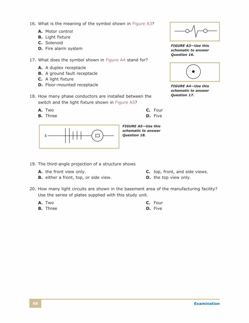
Examination68
16. What is the meaning of the symbol shown in Figure A3?
A. Motor controlB. Light fixtureC. SolenoidD. Fire alarm system
17. What does the symbol shown in Figure A4 stand for?
A. A duplex receptacleB. A ground fault receptacleC. A light fixtureD. Floor-mounted receptacle
18. How many phase conductors are installed between the switch and the light fixture shown in Figure A5?
A. Two C. FourB. Three D. Five
19. The third-angle projection of a structure shows
A. the front view only. C. top, front, and side views.B. either a front, top, or side view. D. the top view only.
20. How many light circuits are shown in the basement area of the manufacturing facility? Use the series of plates supplied with this study unit.
A. Two C. FourB. Three D. Five
FIGURE A3—Use this schematic to answer Question 16.
FIGURE A4—Use this schematic to answer Question 17.
FIGURE A5—Use this schematic to answer Question 18.