
Electrical Interconnection · 2018-07-12 · PCB Terminal Blocks and Pluggable Connectors Volume 2...
76
1 Rail-Mount Terminal Block Systems Full Line Catalog, Volume 1 – Edition 2017/2018 PCB Terminal Blocks and Connectors Full Line Catalog, Volume 2 – Edition 2017/2018 2 3 Automation Technology Full Line Catalog, Volume 3 – Edition 2017/2018 4 Interface Electronic Full Line Catalog, Volume 4 – Edition 2017/2018 5 WINSTA® – The Pluggable Connection System Full Line Catalog, Volume 5 – Edition 2017/2018 6 Marking Full Line Catalog, Volume 6 – Edition 2017/2018 Electrical Interconnection 6XSSOHPHQWDU\ &DWDORJ WR )XOO /LQH &DWDORJV 9ROXPHV Edition 2018/1
Transcript of Electrical Interconnection · 2018-07-12 · PCB Terminal Blocks and Pluggable Connectors Volume 2...
1Rail-Mount Terminal Block SystemsFull Line Catalog, Volume 1 – Edition 2017/2018
PCB Terminal Blocks and ConnectorsFull Line Catalog, Volume 2 – Edition 2017/2018 2 3Automation Technology
Full Line Catalog, Volume 3 – Edition 2017/2018
4Interface ElectronicFull Line Catalog, Volume 4 – Edition 2017/2018 5WINSTA® – The Pluggable Connection System
Full Line Catalog, Volume 5 – Edition 2017/2018 6MarkingFull Line Catalog, Volume 6 – Edition 2017/2018
Electrical Interconnection
Edition 2018/1
1
Rail-Mount Terminal Block Systems
Full Line Catalog, Volume 1 – Edition 2017/2018
Rail-
Mou
nt T
erm
inal
Blo
ck S
yste
ms
Full L
ine
Cata
log
2015
/201
6
PCB Terminal Blocks and Connectors
Full Line Catalog, Volume 2 – Edition 2017/2018
PCB
Term
inal
Blo
cks
and
Conn
ecto
rs
Full L
ine
Cata
log
2017
/201
8
2
2
5
WINSTA® – The Pluggable Connection System
Full Line Catalog, Volume 5 – Edition 2017/2018
WIN
STA®
– T
he P
lugg
able
Con
nect
ion
Syst
em
Full L
ine
Cata
log
2017
/201
8
6
Marking
Full Line Catalog, Volume 6 – Edition 2017/2018
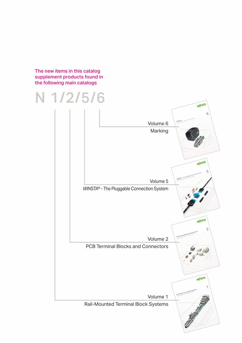
N 1/2/5/6
The new items in this catalog supplement products found in the following main catalogs
Volume 1
Volume 2
Volume 5WINSTA
PageRail-Mount Terminal Block Systems Volume 1 4
PCB Terminal Blocks and Pluggable Connectors Volume 2 14
WINSTA® – The Pluggable Connection System Volume 5 60
Marking Accessories Volume 6 64
Item Number Index 68
Contents
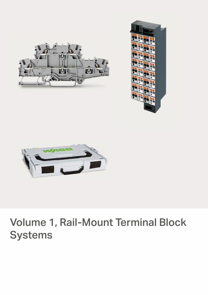
Volume 1, Rail-Mount Terminal Block Systems
3
www.wago.com
Rail-Mount Terminal Block Systems
ContentsVolume 1, Rail-Mount Terminal Block Systems
Products highlighted in RED are new items for Spring 2018
Page
Accessories, Jumpers282, 2009 Series 4
2042 Series 5
2002 Series 7
X-COM®-SYSTEM2-Conductor/1-Pin Double-Deck Carrier Terminal Blocks 2.5 (4 “f-
870 Series 8
Matrix Patchboards with Push-Buttons, 32-Pole – Slimline Ver-sion, for 19” Racks
726 Series 9
L-BOXXSplicing Connector Sets
887 Series 10
221 Series 13

1
4
www.wago.com
Rail-Mount Terminal Block Systems
Volume 1, Section 1 | Rail-Mount Terminal Blocks, TOPJOB® S
Jumper
1-3-4-5
Pack. Unit
Pack. UnitItem No.
Jumper; insulated; IN 30 A; orange
2002 Series and 2009 Series
TOPJOB® SJumper and Push-in Type Wire Jumper
IN 18 A
Push-in type wire jumper
bluered
Item No.
Push-in type wire jumper; insulated; conductor cross-sec-tion: 1.5 mm²; L = 110 mm; for 2001; 2002; 2003 and 2022 Series Rail-Mount Terminal Blocks
Conductor cross-section: 1.5 mm²
282-435/300-000 (5x10)502009-414/000-0062009-414/000-005
(10x10)100(10x10)100

1
5
www.wago.com
1
2
3
4
5 5
5
Rail-Mount Terminal Block Systems
Volume 1, Section 1 | Rail-Mount Terminal Blocks, TOPJOB® S
violetgreenlight greenorangegrayblueredyellow
WMB Multi marking system; plain; 10 strips with 10 markers/card; stretchable from 5 … 5.2 mm
plain
WMB Multi marking system; white; 10 strips with 10 markers/card; stretchable from 5 … 5.2 mm
12-way11-way10-way9-way8-way7-way6-way5-way4-way3-way2-way
Staggered jumper; insulated; IN 25 A; light gray
1 to 101 to 91 to 81 to 71 to 61 to 51 to 41 to 3
Push-in type jumper bar; insulated; IN 25 A; light gray10-way9-way8-way7-way6-way5-way4-way3-way2-way
Push-in type jumper bar; insulated; IN 25 A; light gray
L = 250 mmL = 110 mmL = 60 mm
Push-in type wire jumper; insulated; IN 18 A; 1.5 mm² conductor cross-section
yellow
Protective warning marker; with black high-voltage symbol; for 5 terminal blocks
grayorange
End and intermediate plate; 1 mm thickgray
2-conductor carrier terminal block; 0.25 … 2.5 (4) mm² / 22 … 12 AWG 5.2 mm / 0.205 inch wide
grayorange
End and intermediate plate; 1 mm thickgray
4-conductor carrier terminal block; 0.25 … 2.5 (4) mm² / 22 … 12 AWG 5.2 mm / 0.205 inch wide
gray
gray
orange
orange
End and intermediate plate; 1 mm thick
End and intermediate plate; 1 mm thick
gray
gray
2-conductor carrier terminal block; 0.25 … 2.5 (4) mm² / 22 … 12 AWG 5.2 mm / 0.205 inch wide
3-conductor carrier terminal block; 0.25 … 2.5 (4) mm² / 22 … 12 AWG 5.2 mm / 0.205 inch wide
Accessories for carrier terminal blocksAppropriate marking systems: WMB/Mini-WSB/Marker Strips
(see Full Line Catalog, Volume 1, Section 13)
Pack. UnitItem No.
Component plug; 4-pole; transparent housing; with fiber optics; 10.3 mm wide
Component plug; 8-pole; transparent housing; with fiber optics; 20.7 mm wide
Component plug; 6-pole; transparent housing; with fiber optics; 15.5 mm wide
Component plug; 10-pole; transparent housing; with fiber optics; 25.9 mm wide
Pack. UnitItem No.
See application notes in our Full Line Catalog, Volume 1. Colored push-in type jumper bar Staggered jumper Push-in type wire jumper
5
2042 Series
TOPJOB® SComponent Plug on Carrier Terminal Block 2.5 (4) mm²
Length of 2002-1961: 72.9 mm / 2.87 inch 2-conductor carrier terminal block with additional jumper slot
Length of 2002-1861: 87.5 mm / 3.45 inch 4-conductor carrier terminal block
Length of 2002-1761: 76.8 mm / 3.02 inch 3-conductor carrier terminal block
Length of 2002-1661: 66.5 mm / 2.62 inch 2-conductor carrier terminal block
2
1
3
4
793-5501/000-024793-5501/000-023793-5501/000-017793-5501/000-012793-5501/000-007793-5501/000-006793-5501/000-005793-5501/000-002
793-5501
2002-4822002-4812002-4802002-4792002-4782002-4772002-4762002-4752002-4742002-4732002-472
2002-4402002-4392002-4382002-4372002-4362002-4352002-4342002-433
2002-4102002-4092002-4082002-4072002-4062002-4052002-4042002-4032002-402
2009-4162009-4142009-412
2002-115
2002-19912002-1992
2002-1961
2002-18912002-1892
2002-1861
2002-1691
2002-1791
2002-1692
2002-1792
2002-1661
2002-1761
2042-321
2042-341
2042-331
2042-351
5
5
5
5
(4x25)100
(4x25)100(4x25)100
50
(4x25)100(4x25)100
50
(4x25)
(4x25)
100
100
(4x25)
(4x25)
100
100
50
50
2525252525252525
252525252525252525
(10x10)100(10x10)100(10x10)100
5
5
2525252525252525
100100100
3
6
www.wago.com
110 mm/4.33 in56,7 mm/2.32 in
44,3
mm
/1.7
4 in
Rail-Mount Terminal Block Systems
orange
orange
gray
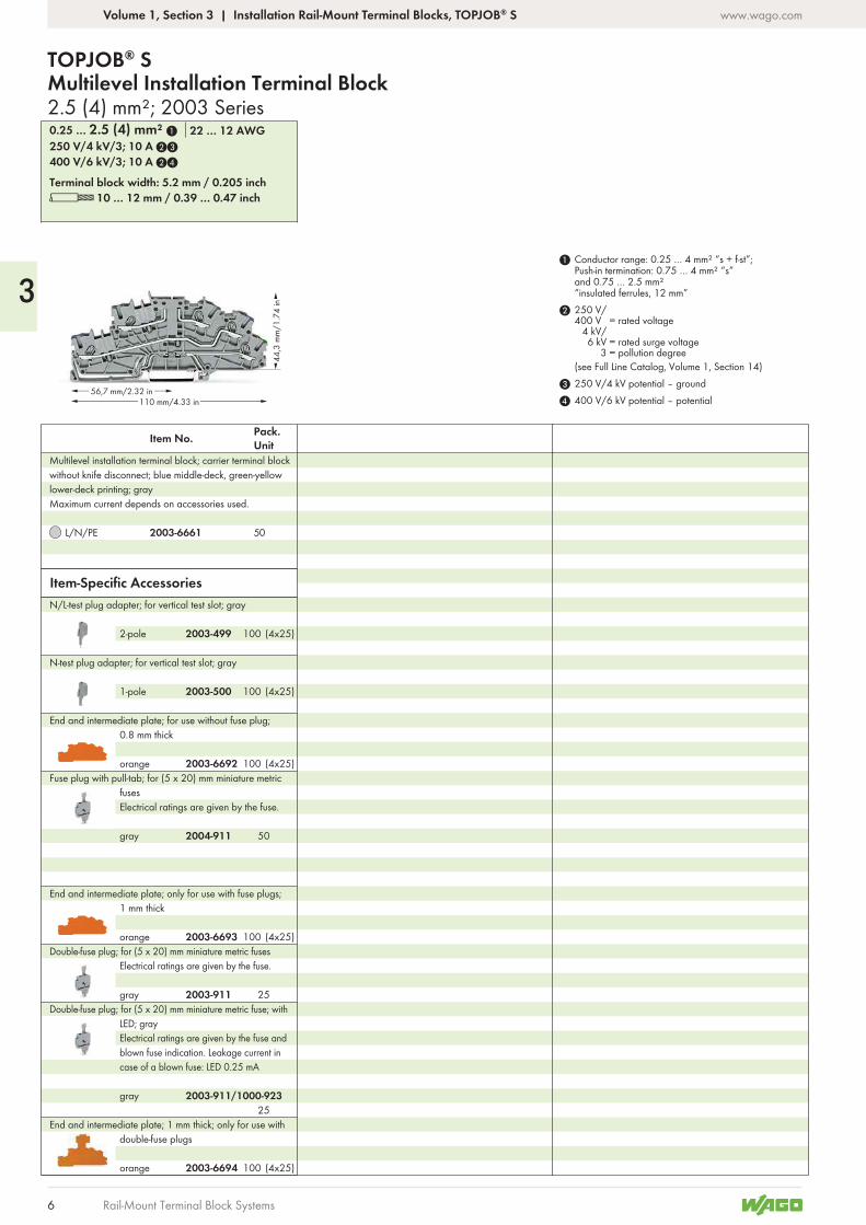
End and intermediate plate; only for use with fuse plugs; 1 mm thick
End and intermediate plate; 1 mm thick; only for use with double-fuse plugs
Fuse plug with pull-tab; for (5 x 20) mm miniature metric fuses Electrical ratings are given by the fuse.
L 10 … 12 mm / 0.39 … 0.47 inchTerminal block width: 5.2 mm / 0.205 inch
400 V/6 kV/3; 10 A 24
250 V/4 kV/3; 10 A 23
0.25 … 2.5 (4) mm² 1 22 … 12 AWG
1-pole
N-test plug adapter; for vertical test slot; gray
2-pole
N/L-test plug adapter; for vertical test slot; gray
Item-Specific Accessories
L/N/PE
Pack. UnitItem No.
Multilevel installation terminal block; carrier terminal block without knife disconnect; blue middle-deck, green-yellow lower-deck printing; grayMaximum current depends on accessories used.
2.5 (4) mm²; 2003 Series
TOPJOB® SMultilevel Installation Terminal Block
4 400 V/6 kV potential – potential3 250 V/4 kV potential – ground
2 250 V/400 V = rated voltage
4 kV/6 kV = rated surge voltage
3 = pollution degree(see Full Line Catalog, Volume 1, Section 14)
1 Conductor range: 0.25 … 4 mm² “s + f-st”; Push-in termination: 0.75 … 4 mm² “s” and 0.75 … 2.5 mm² “insulated ferrules, 12 mm”
orange
End and intermediate plate; for use without fuse plug; 0.8 mm thick
Volume 1, Section 3 | Installation Rail-Mount Terminal Blocks, TOPJOB® S
gray
gray
Double-fuse plug; for (5 x 20) mm miniature metric fuses Electrical ratings are given by the fuse.
Double-fuse plug; for (5 x 20) mm miniature metric fuse; with LED; gray Electrical ratings are given by the fuse and blown fuse indication. Leakage current in case of a blown fuse: LED 0.25 mA
2003-6693
2003-6694
2003-500
2003-499
2003-6661
2004-911
2003-911
2003-911/1000-923
50
(4x25)100
(4x25)100
50
25
25
(4x25)
(4x25)
100
100
(4x25)1002003-6692

7
www.wago.com
Rail-Mount Terminal Block Systems

6
8
www.wago.com
39,8
mm/1
.57 in
52,3 mm/2.06 in91 mm/3.58 in
39,8
mm/1
.57 in
52,3 mm/2.06 in91 mm/3.58 in
Rail-Mount Terminal Block Systems
orangegray
Pin cover; with Mini-WSB marker slot
gray
1-connector female plug; straight
gray
1-conductor female plug; angled
orange
Coding pin; for coding female plugs
1 to 91 to 81 to 71 to 61 to 51 to 41 to 3
Push-in type jumper bar; insulated; IN 18 A; light gray
10-way9-way8-way7-way6-way5-way4-way
1-3-5-7-9
3-way
1-3-5-7
2-way
1-3-5
1-2 3-4 5-6
Push-in type jumper bar; insulated; IN 18 A; light gray
Push-in type jumper bar; insulated; IN 18 A; light gray
Delta jumper; insulated; IN 18 A; light gray
white
Insulation stop; 5 pcs/strip; 0.08 … 0.2 mm² “s” (0.14 mm² “f-st”)
grayorange
End and intermediate plate; 1 mm thick
L 6 … 7 mm / 0.24 … 0.28 inchTerminal block width: 5 mm / 0.197 inch
0.08 … 2.5 (4 “f-st”) mm² 28 … 12 AWG
Pack. UnitItem No.
PE
4-conductor/2-pin double-deck carrier block; 4-conductor/2-pin ground conductor block; internally commoned; green-yellow housing
L 6 … 7 mm / 0.24 … 0.28 inchTerminal block width: 5 mm / 0.197 inch
IN 16 A500 V/6 kV/30.08 … 2.5 (4 “f-st”) mm² 28 … 12 AWG
L/L
L
Pack. UnitItem No.
2-conductor/1-pin double-deck carrier terminal block; through/through terminal block; gray housing
4-conductor/2-pin double-deck carrier terminal block; 4-conductor/2-pin through terminal block; internally commoned; violet conductor entry; gray housing
4 Note: 2-conductor female plugs cannot be used.
3 See application notes in our Full Line Catalog, Volume 1. Insulation stop
2 500 V = Rated voltage6 kV = Rated surge voltage
3 = Pollution degree(see Full Line Catalog, Volume 1, Section 14)
1 Max. insulation diameter: 4.4 mm
Accessories
Accessories
Appropriate marking systems:Mini-WSB/WMB
Appropriate marking systems:Mini-WSB/WMB
1 to 10
2.5 (4 “f-st”) mm²; 870 Series
X-COM®-SYSTEM2-Conducto/1-Pin Double-Deck Carrier Terminal Block
Volume 1, Section 6 | Rail-Mount Terminal Blocks with a Pluggable Connector, X-COM®-SYSTEM, Classic
light gray
Insulation stop; 5 pcs/strip; 0.25 … 0.5 mm²
dark gray
Insulation stop; 5 pcs/strip; 0.75 … 1 mm²
769-439769-438
769-101
769-101/022-000
769-435
870-439870-438870-437870-436870-435870-434870-433
870-410870-409870-408870-407870-406870-405870-404
870-409/011-000
870-403
870-407/011-000
870-402
870-405/011-000
870-406/020-000
280-470
870-1148870-1149
870-1137870-1131
870-1138
1
2
1
3
3
3
4
5050
50
(4x25)100(4x25)100
200
200
(4x25)100
(4x25)100(4x25)100(4x25)100(4x25)100(4x25)100(8x25)200(8x25)200
(2x25)50(4x25)100(4x25)100(4x25)100(4x25)100(4x25)100(4x25)
(4x25)
(8x25)
(4x25)
100
100
200
100
(8x25)200(8x25)200
(8x25)200
(4x25)100(4x25)100
870-440 (2x25)50
(8x25)200
(8x25)200
280-471
280-472
11
9
www.wago.com
2
34,6
24,9
9,75
5
9,5
121
29,9
14,5
33,4
1111
0
131,
9
9,5
Patching side Field side
34,6
24,9
9,75
5
9,5
121
29,9
14,5
33,4
1111
0
131,
9
9,5
1
2
3
4
5
6
7
8
9
10
11
12
13
14
15
16
17
18
19
20
21
22
23
24
25
26
27
28
29
30
31
32
1
2
3
4
5
6
7
8
9
10
11
12
13
14
15
16
17
18
19
20
21
22
23
24
25
26
27
28
29
30
31
32
Patching side Field side
Rail-Mount Terminal Block Systems
Pack. Unit
Pack. Unit
Volume 1, Section 11 | Matrix Patchboards
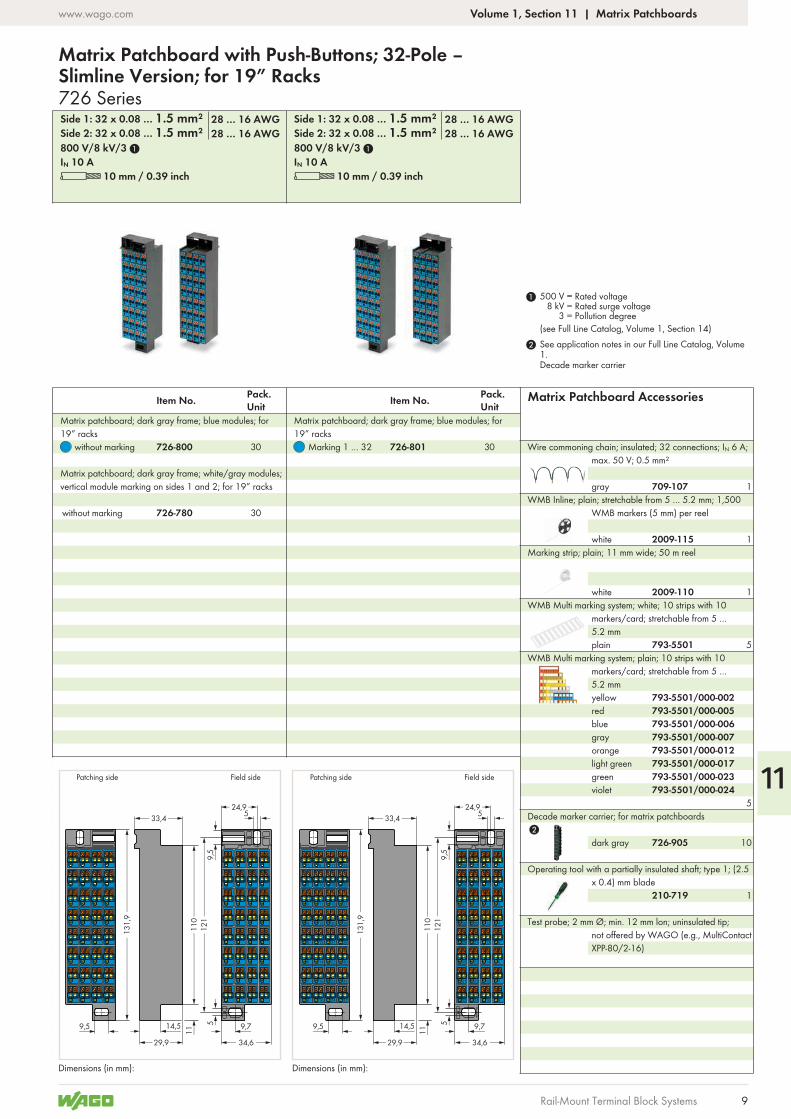
Operating tool with a partially insulated shaft; type 1; (2.5 x 0.4) mm blade
dark gray
Decade marker carrier; for matrix patchboards
gray
Wire commoning chain; insulated; 32 connections; IN 6 A; max. 50 V; 0.5 mm²
L 10 mm / 0.39 inch L 10 mm / 0.39 inchIN 10 A IN 10 A800 V/8 kV/3 1 800 V/8 kV/3 1Side 2: 32 x 0.08 … 1.5 mm² Side 2: 32 x 0.08 … 1.5 mm²28 … 16 AWG 28 … 16 AWGSide 1: 32 x 0.08 … 1.5 mm² Side 1: 32 x 0.08 … 1.5 mm²28 … 16 AWG 28 … 16 AWG
without marking
without marking Marking 1 … 32
Item No. Item No.
Matrix patchboard; dark gray frame; white/gray modules; vertical module marking on sides 1 and 2; for 19” racks
Matrix patchboard; dark gray frame; blue modules; for 19” racks
Matrix patchboard; dark gray frame; blue modules; for 19” racks
See application notes in our Full Line Catalog, Volume 1. Decade marker carrier
2
1 500 V = Rated voltage8 kV = Rated surge voltage
3 = Pollution degree(see Full Line Catalog, Volume 1, Section 14)
Matrix Patchboard Accessories
white
Marking strip; plain; 11 mm wide; 50 m reelwhite
WMB Inline; plain; stretchable from 5 … 5.2 mm; 1,500 WMB markers (5 mm) per reel
violetgreenlight greenorangegrayblueredyellow
WMB Multi marking system; plain; 10 strips with 10 markers/card; stretchable from 5 … 5.2 mm
plain
WMB Multi marking system; white; 10 strips with 10 markers/card; stretchable from 5 … 5.2 mm
Test probe; 2 mm Ø; min. 12 mm lon; uninsulated tip; not offered by WAGO (e.g., MultiContact XPP-80/2-16)
Dimensions (in mm): Dimensions (in mm):
726 Series
Matrix Patchboard with Push-Buttons; 32-Pole – Slimline Version; for 19” Racks
210-719
726-905
709-107
726-780
726-800 726-801
1
1
2009-110
2009-115
5
5
793-5501/000-024793-5501/000-023793-5501/000-017793-5501/000-012793-5501/000-007793-5501/000-006793-5501/000-005793-5501/000-002
793-5501
1
10
30
30 30
1
12
10
www.wago.com
Rail-Mount Terminal Block Systems
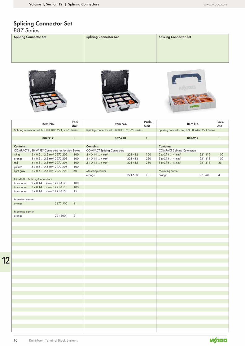
Splicing Connector Set Splicing Connector Set
Pack. Unit
Pack. UnitItem No. Item No.
Splicing connector set; L-BOXX Mini; 221 Series
Contains:COMPACT Splicing Connectors2 x 0.14 … 4 mm² 221-412 1003 x 0.14 … 4 mm² 221-413 1005 x 0.14 … 4 mm² 221-415 25
Mounting carrierorange 221-500 4
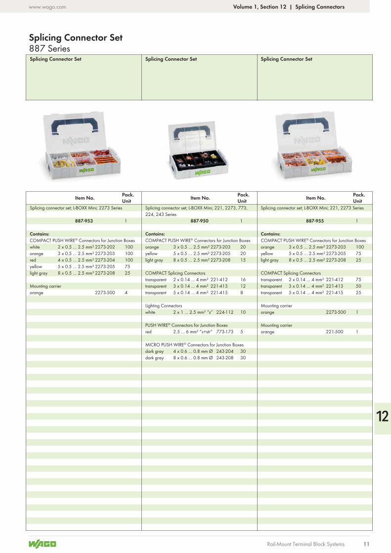
Splicing Connector Set
Pack. UnitItem No.
Splicing connector set; L-BOXX 102; 221, 2273 Series Splicing connector set; L-BOXX 102; 221 Series
Contains:COMPACT PUSH WIRE® Connectors for Junction Boxeswhite 2 x 0.5 … 2.5 mm² 2273-202 100orange 3 x 0.5 … 2.5 mm² 2273-203 100red 4 x 0.5 … 2.5 mm² 2273-204 100yellow 5 x 0.5 … 2.5 mm² 2273-205 100light gray 8 x 0.5 … 2.5 mm² 2273-208 50
COMPACT Splicing Connectorstransparent 2 x 0.14 … 4 mm² 221-412 100transparent 3 x 0.14 … 4 mm² 221-413 100transparent 5 x 0.14 … 4 mm² 221-415 15
Mounting carrierorange 2273-500 2
Mounting carrierorange 221-500 2
Contains:COMPACT Splicing Connectors2 x 0.14 … 4 mm² 221-412 1003 x 0.14 … 4 mm² 221-413 2505 x 0.14 … 4 mm² 221-415 250
Mounting carrierorange 221-500 10
887 SeriesSplicing Connector Set
Volume 1, Section 12 | Splicing Connectors
887-952887-917 887-918 11 1
12
11
www.wago.com
Rail-Mount Terminal Block Systems
Splicing Connector Set Splicing Connector Set
Pack. Unit
Pack. UnitItem No. Item No.
Splicing connector set; L-BOXX Mini; 221, 2273, 773, 224, 243 Series
Splicing connector set; L-BOXX Mini; 221, 2273 SeriesSplicing connector set; L-BOXX Mini; 2273 Series
Contains:COMPACT PUSH WIRE® Connectors for Junction Boxesorange 3 x 0.5 … 2.5 mm² 2273-203 20yellow 5 x 0.5 … 2.5 mm² 2273-205 20light gray 8 x 0.5 … 2.5 mm² 2273-208 15
COMPACT Splicing Connectorstransparent 2 x 0.14 … 4 mm² 221-412 16transparent 3 x 0.14 … 4 mm² 221-413 12transparent 5 x 0.14 … 4 mm² 221-415 8
Lighting Connectorswhite 2 x 1 … 2.5 mm² “s” 224-112 10
PUSH WIRE® Connectors for Junction Boxesred 2.5 … 6 mm² “s+str” 773-173 5
MICRO PUSH WIRE® Connectors for Junction Boxesdark gray 4 x 0.6 … 0.8 mm Ø 243-204 30dark gray 8 x 0.6 … 0.8 mm Ø 243-208 30
Contains:COMPACT PUSH WIRE® Connectors for Junction Boxesorange 3 x 0.5 … 2.5 mm² 2273-203 100yellow 5 x 0.5 … 2.5 mm² 2273-205 75light gray 8 x 0.5 … 2.5 mm² 2273-208 25
COMPACT Splicing Connectorstransparent 2 x 0.14 … 4 mm² 221-412 75transparent 3 x 0.14 … 4 mm² 221-413 50transparent 5 x 0.14 … 4 mm² 221-415 25
Mounting carrierorange 2273-500 1
Mounting carrierorange 221-500 1
Contains:COMPACT PUSH WIRE® Connectors for Junction Boxeswhite 2 x 0.5 … 2.5 mm² 2273-202 100orange 3 x 0.5 … 2.5 mm² 2273-203 100red 4 x 0.5 … 2.5 mm² 2273-204 100yellow 5 x 0.5 … 2.5 mm² 2273-205 75light gray 8 x 0.5 … 2.5 mm² 2273-208 25
Mounting carrierorange 2273-500 4
Splicing Connector Set
Pack. UnitItem No.
887 SeriesSplicing Connector Set
Volume 1, Section 12 | Splicing Connectors
887-950 887-955887-953 1 11
12
12
www.wago.com
Rail-Mount Terminal Block Systems
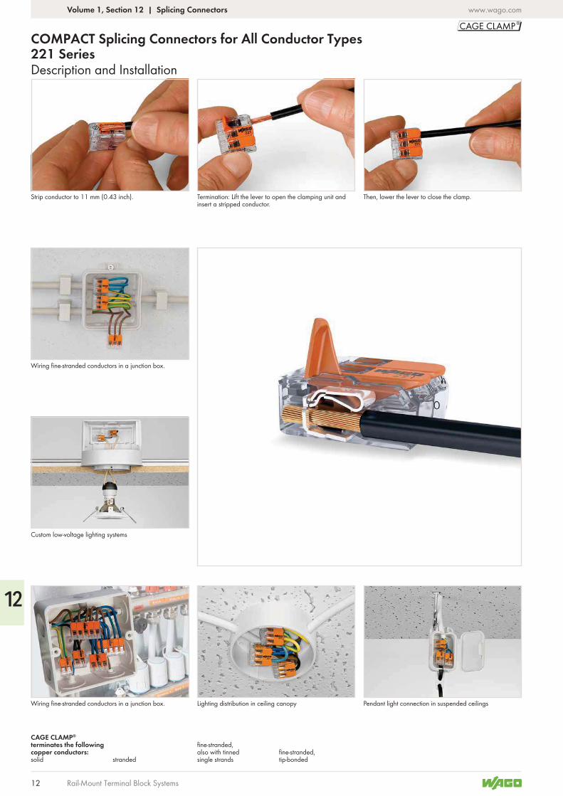
Description and Installation
COMPACT Splicing Connectors for All Conductor Types221 Series
Strip conductor to 11 mm (0.43 inch).
Wiring fine-stranded conductors in a junction box.
Custom low-voltage lighting systems
Termination: Lift the lever to open the clamping unit and insert a stripped conductor.
Lighting distribution in ceiling canopyWiring fine-stranded conductors in a junction box.
Then, lower the lever to close the clamp.
Pendant light connection in suspended ceilings
fine-stranded, also with tinned single strandsstranded
CAGE CLAMP® terminates the following copper conductors:solid
fine-stranded, tip-bonded
Volume 1, Section 12 | Splicing Connectors
12
13
www.wago.com
36,7
10,1
21,1
16
10,1
21,122,9
10,1
21,1
84,2 mm/3.71 in
28,3
mm
/1.
11 in
Rail-Mount Terminal Block Systems
Dimensions in mm
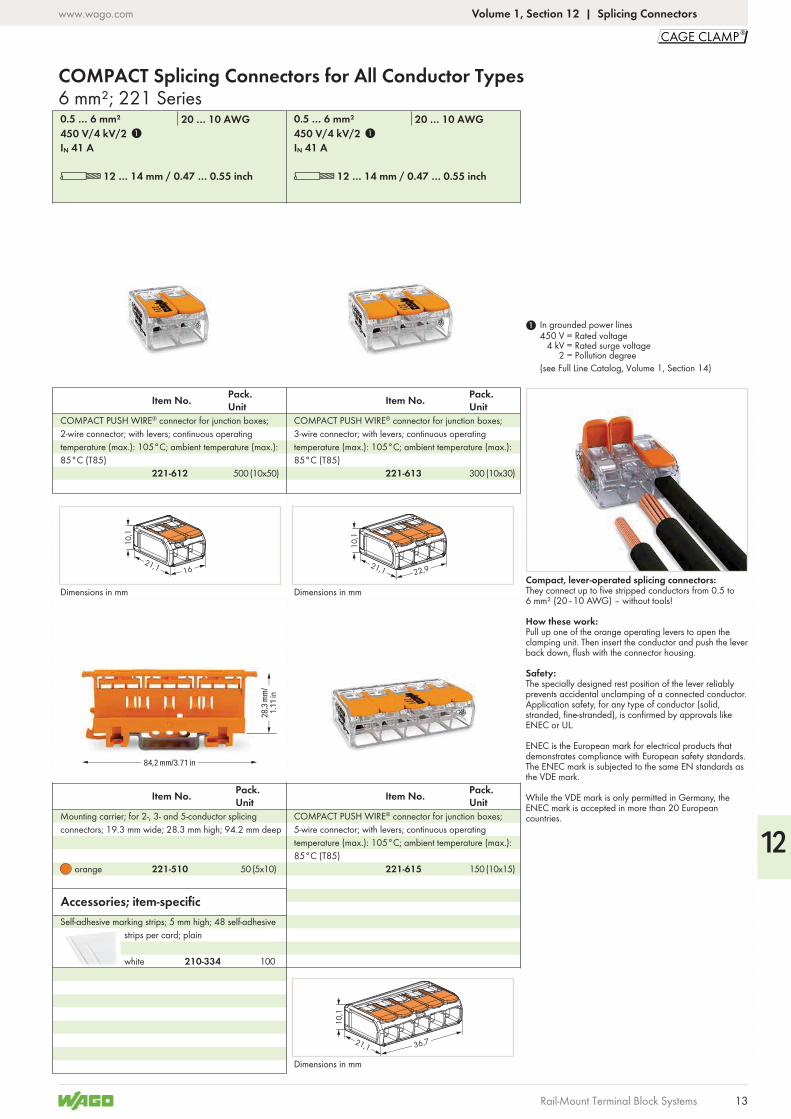
L 12 … 14 mm / 0.47 … 0.55 inch
IN 41 A450 V/4 kV/20.5 … 6 mm² 20 … 10 AWG
Pack. UnitItem No.
COMPACT PUSH WIRE® connector for junction boxes; 3-wire connector; with levers; continuous operating temperature (max.): 105°C; ambient temperature (max.): 85°C (T85)
Pack. Unit
Pack. Unit Item No.Item No.
COMPACT PUSH WIRE® connector for junction boxes; 5-wire connector; with levers; continuous operating temperature (max.): 105°C; ambient temperature (max.): 85°C (T85)
Mounting carrier; for 2-, 3- and 5-conductor splicing connectors; 19.3 mm wide; 28.3 mm high; 94.2 mm deep
Dimensions in mm
L 12 … 14 mm / 0.47 … 0.55 inch
IN 41 A450 V/4 kV/20.5 … 6 mm² 20 … 10 AWG
Pack. UnitItem No.
COMPACT PUSH WIRE® connector for junction boxes; 2-wire connector; with levers; continuous operating temperature (max.): 105°C; ambient temperature (max.): 85°C (T85)
Dimensions in mm
1 In grounded power lines450 V = Rated voltage
4 kV = Rated surge voltage2 = Pollution degree
(see Full Line Catalog, Volume 1, Section 14)
Compact, lever-operated splicing connectors:They connect up to five stripped conductors from 0.5 to 6 mm² (20–10 AWG) – without tools!
How these work:Pull up one of the orange operating levers to open the clamping unit. Then insert the conductor and push the lever back down, flush with the connector housing.
Safety:The specially designed rest position of the lever reliably prevents accidental unclamping of a connected conductor.Application safety, for any type of conductor (solid, stranded, fine-stranded), is confirmed by approvals like ENEC or UL.
ENEC is the European mark for electrical products that demonstrates compliance with European safety standards. The ENEC mark is subjected to the same EN standards as the VDE mark.
While the VDE mark is only permitted in Germany, the ENEC mark is accepted in more than 20 European countries.
Volume 1, Section 12 | Splicing Connectors
6 mm²; 221 SeriesCOMPACT Splicing Connectors for All Conductor Types
white
Self-adhesive marking strips; 5 mm high; 48 self-adhesive strips per card; plain
Accessories; item-specific
orange
221-613
221-615221-510
221-612
1 1
(10x30)300(10x50)500
(10x15)(5x10) 15050
210-334 100
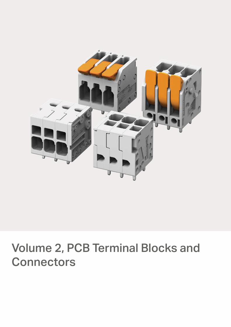
Volume 2, PCB Terminal Blocks andConnectors
www.wago.com
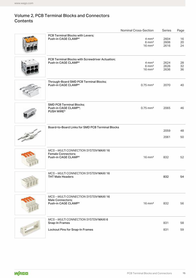
Volume 2, PCB Terminal Blocks and ConnectorsContents
PCB Terminal Blocks with Levers; Push-in CAGE CLAMP®
PCB Terminal Blocks with Screwdriver Actuation;Push-in CAGE CLAMP®
Through-Board SMD PCB Terminal Blocks;Push-in CAGE CLAMP®
SMD PCB Terminal Blocks;Push-in CAGE CLAMP®; PUSH WIRE®
Board-to-Board Links for SMD PCB Terminal Blocks 2059 48
2061 50
MCS – MULTI CONNECTION SYSTEM MAXI 16Female Connectors;Push-in CAGE CLAMP®
MCS – MULTI CONNECTION SYSTEM MAXI 16THT Male Headers 832 54
MCS – MULTI CONNECTION SYSTEM MAXI 16Male Connectors;Push-in CAGE CLAMP®
MCS – MULTI CONNECTION SYSTEM MAXI 6Snap-In Frames 831 58
Lockout Pins for Snap-In Frames 831 59
Nominal Cross-Section Series Page
PCB Terminal Blocks and Connectors 15
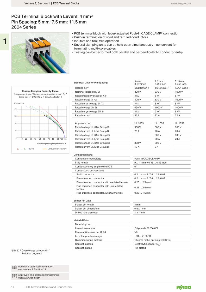
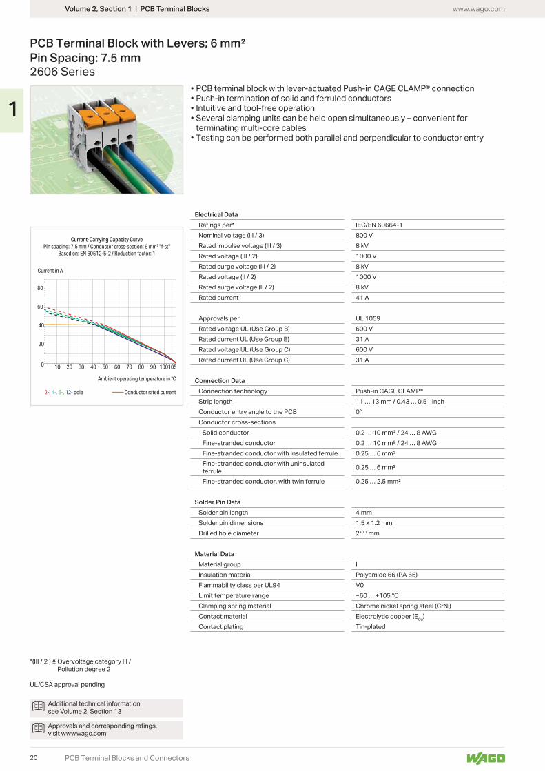
10 20 30 40 50 60 70 80 90 100 1050
20
30
40
10
2-, 4-, 6-, 12-
Current-Carrying Capacity CurvePin spacing: 5 mm / Conductor cross-section: 4 mm² "f-st"
Based on: EN 60512-5-2 / Reduction factor: 1
Current in A
Ambient operating temperature in °C
Conductor rated currentpole
Volume 2, Section 1 | PCB Terminal Blocks www.wago.com
PCB Terminal Blocks and Connectors
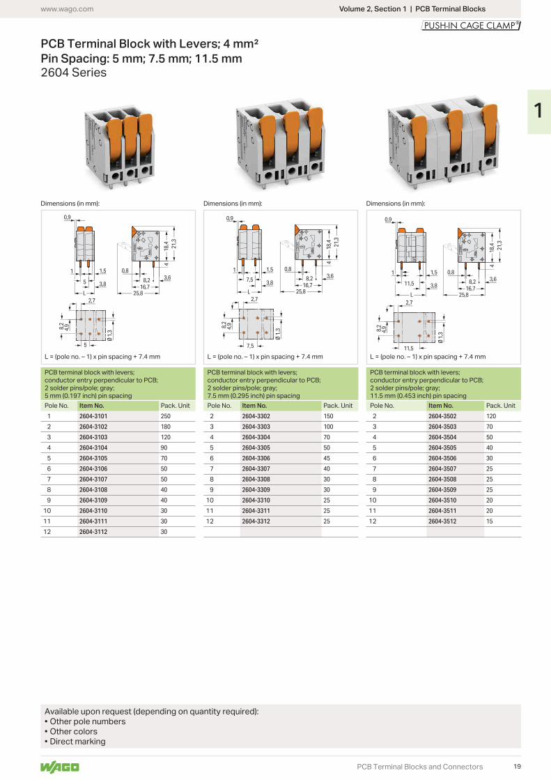
PCB Terminal Block with Levers; 4 mm² Pin Spacing: 5 mm; 7.5 mm; 11.5 mm2604 Series
Electrical Data for Pin Spacing 5 mm0.197 inch
7.5 mm 0.295 inch
11.5 mm0.453 inch
Ratings per* IEC/EN 60664-1 IEC/EN 60664-1 IEC/EN 60664-1
Nominal voltage (III / 3) 320 V 630 V 1000 VRated impulse voltage (III / 3) 4 kV 6 kV 8 kVRated voltage (III / 2) 400 V 630 V 1000 VRated surge voltage (III / 2) 4 kV 6 kV 8 kVRated voltage (II / 2) 630 V 1000 V 1000 VRated surge voltage (II / 2) 4 kV 6 kV 8 kVRated current 32 A 32 A 32 A
Approvals per UL 1059 UL 1059 UL 1059Rated voltage UL (Use Group B) 300 V 300 V 600 VRated current UL (Use Group B) 20 A 20 A 20 ARated voltage UL (Use Group C) 300 V 600 VRated current UL (Use Group C) 20 A 20 ARated voltage UL (Use Group D) 300 V 600 VRated current UL (Use Group D) 10 A 5 A
Connection DataConnection technology Push-in CAGE CLAMP®Strip length 9 … 11 mm / 0.35 … 0.43 inchConductor entry angle to the PCB 0°Conductor cross-sections
Solid conductorFine-stranded conductorFine-stranded conductor with insulated ferruleFine-stranded conductor with uninsulated ferruleFine-stranded conductor, with twin ferrule
Solder Pin DataSolder pin length 4 mmSolder pin dimensions 0.8 x 1 mmDrilled hole diameter 1.3+0.1 mm
Material DataMaterial group IInsulation material Polyamide 66 (PA 66)Flammability class per UL94 V0Limit temperature range … +105 °CClamping spring material Chrome nickel spring steel (CrNi)Contact material Electrolytic copper (ECu)Contact plating Tin-plated
• PCB terminal block with lever-actuated Push-in CAGE CLAMP® connection• Push-in termination of solid and ferruled conductors• Intuitive and tool-free operation• Several clamping units can be held open simultaneously – convenient for
terminating multi-core cables• Testing can be performed both parallel and perpendicular to conductor entry
Additional technical information, see Volume 2, Section 13
Approvals and corresponding ratings, visit www.wago.com
Pollution degree 2
16
1
5
2,7
8,2
2,9
Ø 1
,3
25,7
16,7
419,2
16,38,2 5,2
0,8
0,9
1 1,5
7,5 3,8
L
25,7
16,7
4
19,216,38,2 5,2
0,81 1,5
11,5 3,8
2,7
8,2
2,9
0,9
11,5
Ø 1
,3
L
25,7
16,7
4
19,216,38,2 5,2
0,8
0,9
1 1,5
5
5
3,8
2,7
8,2
2,9
Ø 1
,3
L
Volume 2, Section 1 | PCB Terminal Blockswww.wago.com
PCB Terminal Blocks and Connectors
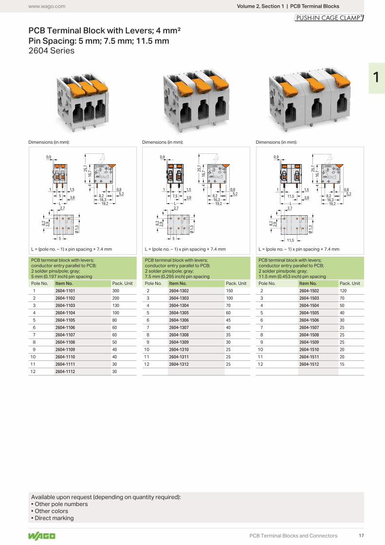
PCB Terminal Block with Levers; 4 mm² Pin Spacing: 5 mm; 7.5 mm; 11.5 mm2604 Series
Dimensions (in mm): Dimensions (in mm): Dimensions (in mm):
PCB terminal block with levers; conductor entry parallel to PCB; 2 solder pins/pole; gray; 5 mm (0.197 inch) pin spacing
PCB terminal block with levers; conductor entry parallel to PCB; 2 solder pins/pole; gray; 7.5 mm (0.295 inch) pin spacing
PCB terminal block with levers; conductor entry parallel to PCB; 2 solder pins/pole; gray; 11.5 mm (0.453 inch) pin spacing
Pole No. Item No. Pack. Unit Pole No. Item No. Pack. Unit Pole No. Item No. Pack. Unit2604-1101 300 2604-1302 150 2604-1502 120
2604-1102 200 2604-1303 100 2604-1503 70
2604-1103 130 2604-1304 70 2604-1504 50
2604-1104 100 2604-1305 60 2604-1505 40
2604-1105 80 2604-1306 45 2604-1506 30
2604-1106 60 2604-1307 40 2604-1507 25
2604-1107 60 2604-1308 35 2604-1508 25
2604-1108 50 2604-1309 30 2604-1509 25
2604-1109 40 10 2604-1310 25 10 2604-1510 20
10 2604-1110 40 11 2604-1311 25 11 2604-1511 20
11 2604-1111 30 12 2604-1312 25 12 2604-1512 15
12 2604-1112 30
Available upon request (depending on quantity required):• Other pole numbers• Other colors• Direct marking
17
1
10 20 30 40 50 60 70 80 90 100 1050
20
30
40
10
2-, 4-, 6-, 12-
Current-Carrying Capacity CurvePin spacing: 5 mm / Conductor cross-section: 4 mm² "f-st"
Based on: EN 60512-5-2 / Reduction factor: 1
Current in A
Ambient operating temperature in °C
Conductor rated currentpole
Volume 2, Section 1 | PCB Terminal Blocks www.wago.com
PCB Terminal Blocks and Connectors
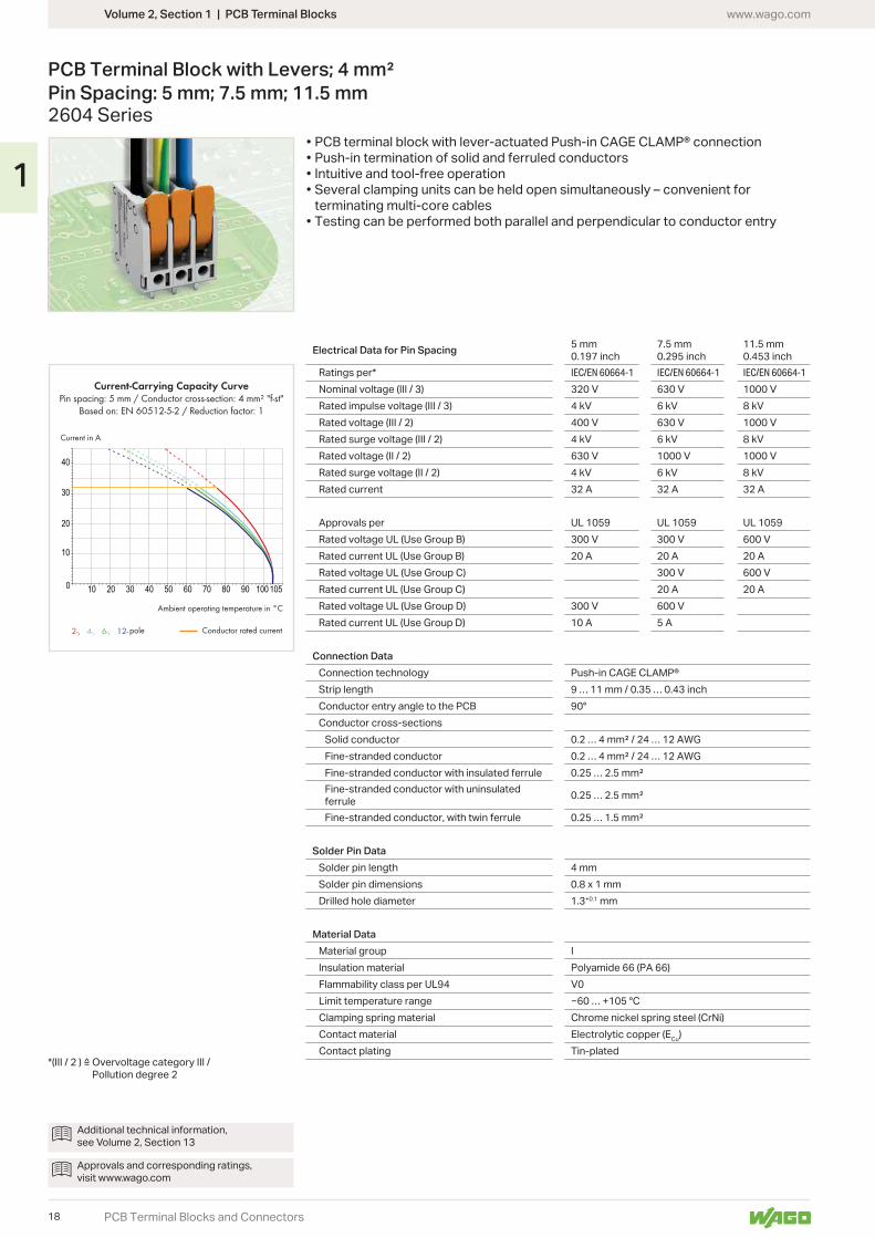
PCB Terminal Block with Levers; 4 mm² Pin Spacing: 5 mm; 7.5 mm; 11.5 mm2604 Series
Electrical Data for Pin Spacing 5 mm0.197 inch
7.5 mm 0.295 inch
11.5 mm0.453 inch
Ratings per* IEC/EN 60664-1 IEC/EN 60664-1 IEC/EN 60664-1
Nominal voltage (III / 3) 320 V 630 V 1000 VRated impulse voltage (III / 3) 4 kV 6 kV 8 kVRated voltage (III / 2) 400 V 630 V 1000 VRated surge voltage (III / 2) 4 kV 6 kV 8 kVRated voltage (II / 2) 630 V 1000 V 1000 VRated surge voltage (II / 2) 4 kV 6 kV 8 kVRated current 32 A 32 A 32 A
Approvals per UL 1059 UL 1059 UL 1059Rated voltage UL (Use Group B) 300 V 300 V 600 VRated current UL (Use Group B) 20 A 20 A 20 ARated voltage UL (Use Group C) 300 V 600 VRated current UL (Use Group C) 20 A 20 ARated voltage UL (Use Group D) 300 V 600 VRated current UL (Use Group D) 10 A 5 A
Connection DataConnection technology Push-in CAGE CLAMP®Strip length 9 … 11 mm / 0.35 … 0.43 inchConductor entry angle to the PCB 90°Conductor cross-sections
Solid conductorFine-stranded conductorFine-stranded conductor with insulated ferruleFine-stranded conductor with uninsulated ferruleFine-stranded conductor, with twin ferrule
Solder Pin DataSolder pin length 4 mmSolder pin dimensions 0.8 x 1 mmDrilled hole diameter 1.3+0.1 mm
Material DataMaterial group IInsulation material Polyamide 66 (PA 66)Flammability class per UL94 V0Limit temperature range … +105 °CClamping spring material Chrome nickel spring steel (CrNi)Contact material Electrolytic copper (ECu)Contact plating Tin-plated
Pollution degree 2
Additional technical information, see Volume 2, Section 13
Approvals and corresponding ratings, visit www.wago.com
• PCB terminal block with lever-actuated Push-in CAGE CLAMP® connection• Push-in termination of solid and ferruled conductors• Intuitive and tool-free operation• Several clamping units can be held open simultaneously – convenient for
terminating multi-core cables• Testing can be performed both parallel and perpendicular to conductor entry
18
1
25,816,7
8,2
418
,4 21,3
0,83,6
0,9
1 1,5
3,87,5
8,2
4,9
2,7
7,5
Ø 1
,3
L
0,9
25,816,7
8,2
418
,4 21,3
0,83,6
1 1,5
3,811,5
2,7
8,2
4,9
11,5
Ø 1
,3
L
1
25,816,7
8,2
418
,4 21,3
0,8
0,9
1,5
5
3,83,6
5
2,7
8,2
Ø 1
,34,9
L
Volume 2, Section 1 | PCB Terminal Blockswww.wago.com
PCB Terminal Blocks and Connectors
PCB Terminal Block with Levers; 4 mm² Pin Spacing: 5 mm; 7.5 mm; 11.5 mm2604 Series
Dimensions (in mm): Dimensions (in mm): Dimensions (in mm):
PCB terminal block with levers; conductor entry perpendicular to PCB; 2 solder pins/pole; gray; 5 mm (0.197 inch) pin spacing
PCB terminal block with levers; conductor entry perpendicular to PCB; 2 solder pins/pole; gray; 7.5 mm (0.295 inch) pin spacing
PCB terminal block with levers; conductor entry perpendicular to PCB; 2 solder pins/pole; gray; 11.5 mm (0.453 inch) pin spacing
Pole No. Item No. Pack. Unit Pole No. Item No. Pack. Unit Pole No. Item No. Pack. Unit2604-3101 250 2604-3302 150 2604-3502 120
2604-3102 180 2604-3303 100 2604-3503 70
2604-3103 120 2604-3304 70 2604-3504 50
2604-3104 90 2604-3305 50 2604-3505 40
2604-3105 70 2604-3306 45 2604-3506 30
2604-3106 50 2604-3307 40 2604-3507 25
2604-3107 50 2604-3308 30 2604-3508 25
2604-3108 40 2604-3309 30 2604-3509 25
2604-3109 40 10 2604-3310 25 10 2604-3510 20
10 2604-3110 30 11 2604-3311 25 11 2604-3511 20
11 2604-3111 30 12 2604-3312 25 12 2604-3512 15
12 2604-3112 30
Available upon request (depending on quantity required):• Other pole numbers• Other colors• Direct marking
19
1
10 20 30 40 50 60 70 80 90 1001050
20
40
60
80
2-, 4-, 6-, 12-
Current-Carrying Capacity CurvePin spacing: 7,5 mm / Conductor cross-section: 6 mm2 "f-st"
Based on: EN 60512-5-2 / Reduction factor: 1
Current in A
Conductor rated current
Ambient operating temperature in °C
pole
Volume 2, Section 1 | PCB Terminal Blocks www.wago.com
PCB Terminal Blocks and Connectors
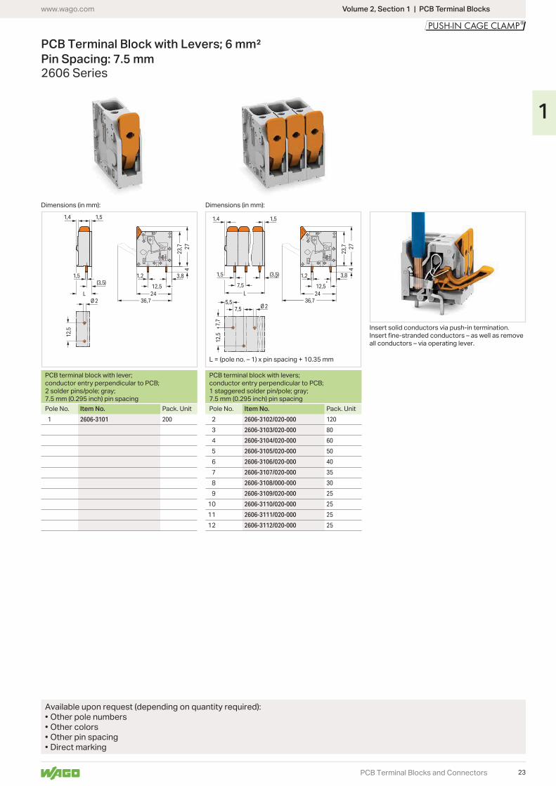
PCB Terminal Block with Levers; 6 mm² Pin Spacing: 7.5 mm2606 Series
Electrical DataRatings per* IEC/EN 60664-1Nominal voltage (III / 3) 800 VRated impulse voltage (III / 3) 8 kVRated voltage (III / 2) 1000 VRated surge voltage (III / 2) 8 kVRated voltage (II / 2) 1000 VRated surge voltage (II / 2) 8 kVRated current 41 A
Approvals per UL 1059Rated voltage UL (Use Group B) 600 VRated current UL (Use Group B) 31 ARated voltage UL (Use Group C) 600 VRated current UL (Use Group C) 31 A
Connection DataConnection technology Push-in CAGE CLAMP®Strip length 11 … 13 mm / 0.43 … 0.51 inchConductor entry angle to the PCB 0°Conductor cross-sections
Solid conductorFine-stranded conductorFine-stranded conductor with insulated ferruleFine-stranded conductor with uninsulated ferruleFine-stranded conductor, with twin ferrule
Solder Pin DataSolder pin length 4 mmSolder pin dimensions 1.5 x 1.2 mmDrilled hole diameter 2+0.1 mm
Material DataMaterial group IInsulation material Polyamide 66 (PA 66)Flammability class per UL94 V0Limit temperature range … +105 °CClamping spring material Chrome nickel spring steel (CrNi)Contact material Electrolytic copper (ECu)Contact plating Tin-plated
• PCB terminal block with lever-actuated Push-in CAGE CLAMP® connection• Push-in termination of solid and ferruled conductors• Intuitive and tool-free operation• Several clamping units can be held open simultaneously – convenient for
terminating multi-core cables• Testing can be performed both parallel and perpendicular to conductor entry
Additional technical information, see Volume 2, Section 13
Approvals and corresponding ratings, visit www.wago.com
Pollution degree 2
UL/CSA approval pending
20
1
1,5
1,4 1,5
(3,5)
7,5
7,5212
,5
5,5Ø 2
36,7
24
1,2
12,52124,3
4
L
1,5(3,5)
1,4 1,5
36,7
24
1,2
12,52124,3
4
12,5
Ø 2L
Volume 2, Section 1 | PCB Terminal Blockswww.wago.com
PCB Terminal Blocks and Connectors
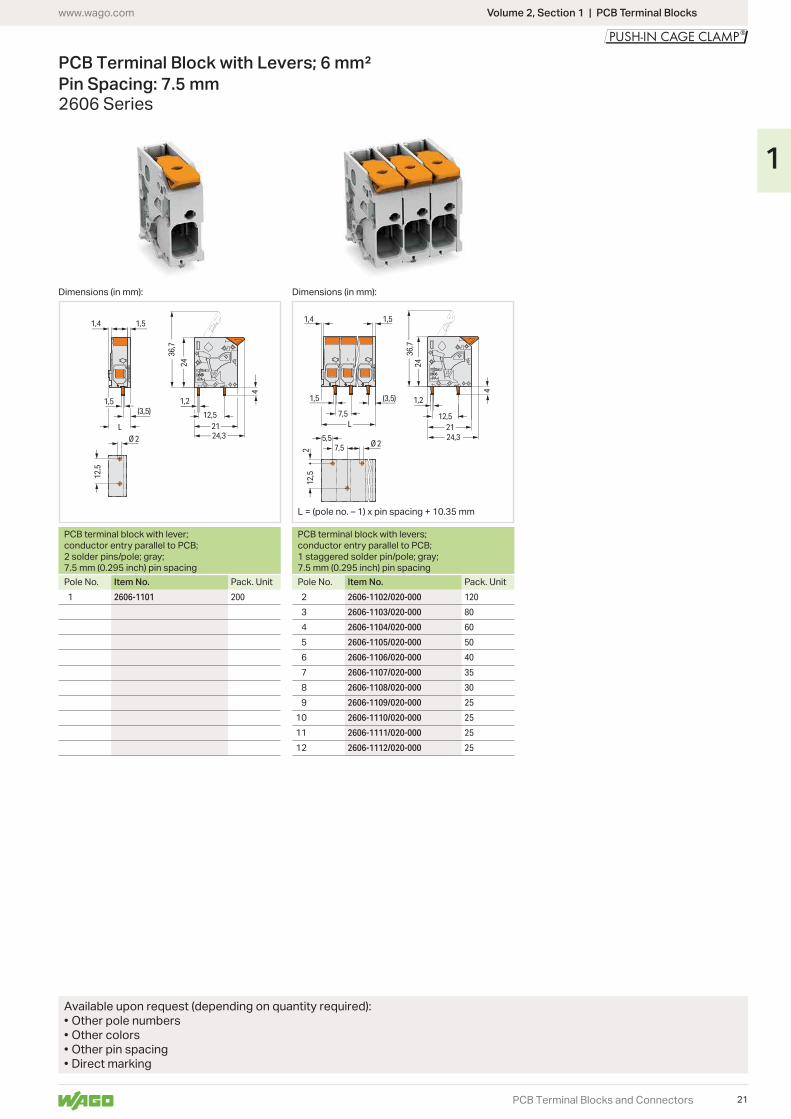
PCB Terminal Block with Levers; 6 mm² Pin Spacing: 7.5 mm2606 Series
Dimensions (in mm):Dimensions (in mm):
PCB terminal block with lever; conductor entry parallel to PCB; 2 solder pins/pole; gray; 7.5 mm (0.295 inch) pin spacing
PCB terminal block with levers; conductor entry parallel to PCB; 1 staggered solder pin/pole; gray; 7.5 mm (0.295 inch) pin spacing
Pole No. Item No. Pack. Unit Pole No. Item No. Pack. Unit2606-1101 200 2606-1102/020-000 120
2606-1103/020-000 80
2606-1104/020-000 60
2606-1105/020-000 50
2606-1106/020-000 40
2606-1107/020-000 35
2606-1108/020-000 30
2606-1109/020-000 25
10 2606-1110/020-000 25
11 2606-1111/020-000 25
12 2606-1112/020-000 25
Available upon request (depending on quantity required):• Other pole numbers• Other colors• Other pin spacing• Direct marking
21
1
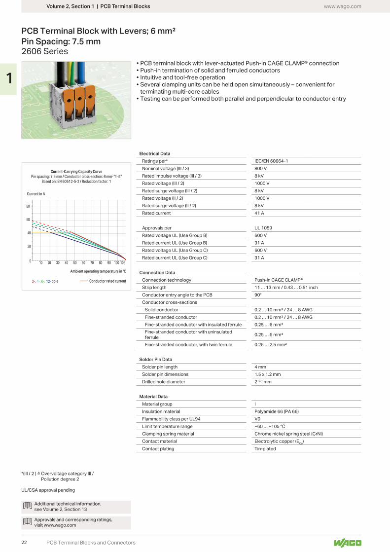
10 20 30 40 50 60 70 80 90 100 1050
20
40
60
80
2-, 4-, 6-, 12-
Current-Carrying Capacity CurvePin spacing: 7,5 mm / Conductor cross-section: 6 mm2 "f-st"
Based on: EN 60512-5-2 / Reduction factor: 1
Current in A
pole Conductor rated current
Ambient operating temperature in °C
Volume 2, Section 1 | PCB Terminal Blocks www.wago.com
PCB Terminal Blocks and Connectors
PCB Terminal Block with Levers; 6 mm² Pin Spacing: 7.5 mm2606 Series
Electrical DataRatings per* IEC/EN 60664-1Nominal voltage (III / 3) 800 VRated impulse voltage (III / 3) 8 kVRated voltage (III / 2) 1000 VRated surge voltage (III / 2) 8 kVRated voltage (II / 2) 1000 VRated surge voltage (II / 2) 8 kVRated current 41 A
Approvals per UL 1059Rated voltage UL (Use Group B) 600 VRated current UL (Use Group B) 31 ARated voltage UL (Use Group C) 600 VRated current UL (Use Group C) 31 A
Connection DataConnection technology Push-in CAGE CLAMP®Strip length 11 … 13 mm / 0.43 … 0.51 inchConductor entry angle to the PCB 90°Conductor cross-sections
Solid conductorFine-stranded conductorFine-stranded conductor with insulated ferruleFine-stranded conductor with uninsulated ferruleFine-stranded conductor, with twin ferrule
Solder Pin DataSolder pin length 4 mmSolder pin dimensions 1.5 x 1.2 mmDrilled hole diameter 2+0.1 mm
Material DataMaterial group IInsulation material Polyamide 66 (PA 66)Flammability class per UL94 V0Limit temperature range … +105 °CClamping spring material Chrome nickel spring steel (CrNi)Contact material Electrolytic copper (ECu)Contact plating Tin-plated
Additional technical information, see Volume 2, Section 13
Approvals and corresponding ratings, visit www.wago.com
• PCB terminal block with lever-actuated Push-in CAGE CLAMP® connection• Push-in termination of solid and ferruled conductors• Intuitive and tool-free operation• Several clamping units can be held open simultaneously – convenient for
terminating multi-core cables• Testing can be performed both parallel and perpendicular to conductor entry
Pollution degree 2
UL/CSA approval pending
22
1
1,5(3,5)
1,4 1,5
12,5
Ø 2 36,7
2723
,7
2412,5
1,2 3,8
4
L36,7
2723
,7
2412,5
1,2
4
7,5
12,5
5,5
1,4 1,5
1,5 (3,5)
7,5
Ø 2
7,7
3,8
L
Volume 2, Section 1 | PCB Terminal Blockswww.wago.com
PCB Terminal Blocks and Connectors
PCB Terminal Block with Levers; 6 mm² Pin Spacing: 7.5 mm2606 Series
Dimensions (in mm): Dimensions (in mm):
PCB terminal block with lever; conductor entry perpendicular to PCB; 2 solder pins/pole; gray; 7.5 mm (0.295 inch) pin spacing
PCB terminal block with levers; conductor entry perpendicular to PCB; 1 staggered solder pin/pole; gray; 7.5 mm (0.295 inch) pin spacing
Pole No. Item No. Pack. Unit Pole No. Item No. Pack. Unit2606-3101 200 2606-3102/020-000 120
2606-3103/020-000 80
2606-3104/020-000 60
2606-3105/020-000 50
2606-3106/020-000 40
2606-3107/020-000 35
2606-3108/000-000 30
2606-3109/020-000 25
10 2606-3110/020-000 25
11 2606-3111/020-000 25
12 2606-3112/020-000 25
Available upon request (depending on quantity required):• Other pole numbers• Other colors• Other pin spacing• Direct marking
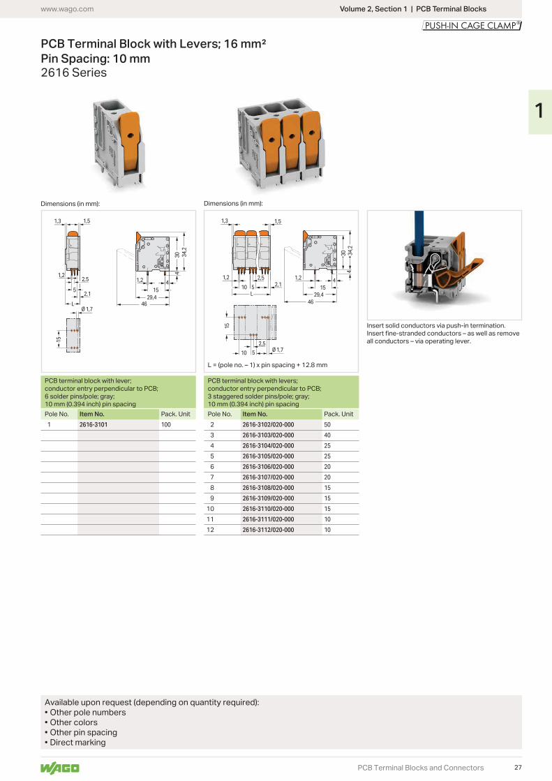
Insert solid conductors via push-in termination.
all conductors – via operating lever.
23
1
10 20 30 40 50 60 70 80 90 100 1050
40
80
100
140
2-, 4-, 6-, 12-
Current-Carrying Capacity CurvePin spacing: 10 mm / Conductor cross-section: 16 mm2 "f-st"
Based on: EN 60512-5-2 / Reduction factor: 1
Current in A
pole Conductor rated current
Ambient operating temperature in °C
Volume 2, Section 1 | PCB Terminal Blocks www.wago.com
PCB Terminal Blocks and Connectors
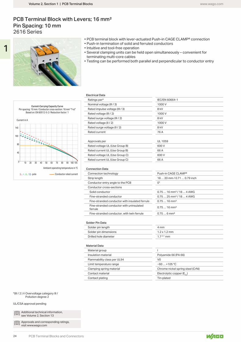
PCB Terminal Block with Levers; 16 mm² Pin Spacing: 10 mm2616 Series
Electrical DataRatings per* IEC/EN 60664-1Nominal voltage (III / 3) 1000 VRated impulse voltage (III / 3) 8 kVRated voltage (III / 2) 1000 VRated surge voltage (III / 2) 8 kVRated voltage (II / 2) 1000 VRated surge voltage (II / 2) 8 kVRated current 76 A
Approvals per UL 1059Rated voltage UL (Use Group B) 600 VRated current UL (Use Group B) 66 ARated voltage UL (Use Group C) 600 VRated current UL (Use Group C) 66 A
Connection DataConnection technology Push-in CAGE CLAMP®Strip length 18 … 20 mm / 0.71 … 0.79 inchConductor entry angle to the PCB 0°Conductor cross-sections
Solid conductorFine-stranded conductorFine-stranded conductor with insulated ferruleFine-stranded conductor with uninsulated ferruleFine-stranded conductor, with twin ferrule
Solder Pin DataSolder pin length 4 mmSolder pin dimensions 1.2 x 1.2 mmDrilled hole diameter 1.7+0.1 mm
Material DataMaterial group IInsulation material Polyamide 66 (PA 66)Flammability class per UL94 V0Limit temperature range … +105 °CClamping spring material Chrome nickel spring steel (CrNi)Contact material Electrolytic copper (ECu)Contact plating Tin-plated
Additional technical information, see Volume 2, Section 13
Approvals and corresponding ratings, visit www.wago.com
Pollution degree 2
UL/CSA approval pending
• PCB terminal block with lever-actuated Push-in CAGE CLAMP® connection• Push-in termination of solid and ferruled conductors• Intuitive and tool-free operation• Several clamping units can be held open simultaneously – convenient for
terminating multi-core cables• Testing can be performed both parallel and perpendicular to conductor entry
24
1
5
1,22,5
1,3 1,5
2,1
Ø 1,7
15
3227,8
10,215
1,2
33,2
49,8
4
1,2
L
10
1,2 2,5
5
1,3 1,5
2,1
Ø 1,74,4
10 5
2,5
2,615
3227,8
10,215
1,2
33,2
49,8
4
1,2
L
Volume 2, Section 1 | PCB Terminal Blockswww.wago.com
PCB Terminal Blocks and Connectors
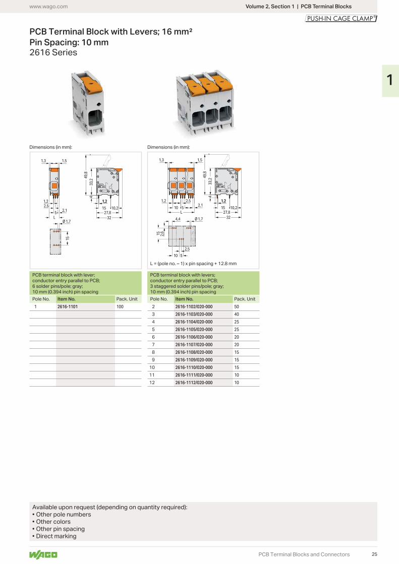
PCB Terminal Block with Levers; 16 mm² Pin Spacing: 10 mm2616 Series
Dimensions (in mm): Dimensions (in mm):
PCB terminal block with lever; conductor entry parallel to PCB; 6 solder pins/pole; gray; 10 mm (0.394 inch) pin spacing
PCB terminal block with levers; conductor entry parallel to PCB; 3 staggered solder pins/pole; gray; 10 mm (0.394 inch) pin spacing
Pole No. Item No. Pack. Unit Pole No. Item No. Pack. Unit2616-1101 100 2616-1102/020-000 50
2616-1103/020-000 40
2616-1104/020-000 25
2616-1105/020-000 25
2616-1106/020-000 20
2616-1107/020-000 20
2616-1108/020-000 15
2616-1109/020-000 15
10 2616-1110/020-000 15
11 2616-1111/020-000 10
12 2616-1112/020-000 10
Available upon request (depending on quantity required):• Other pole numbers• Other colors• Other pin spacing• Direct marking
25
1
10 20 30 40 50 60 70 80 90 1001050
40
80
100
140
2-, 4-, 6-, 12-
Current-Carrying Capacity CurvePin spacing: 10 mm / Conductor cross-section: 16 mm2 "f-st"
Based on: EN 60512-5-2 / Reduction factor: 1
Current in A
pole
Ambient operating temperature in °C
Conductor rated current
Volume 2, Section 1 | PCB Terminal Blocks www.wago.com
PCB Terminal Blocks and Connectors
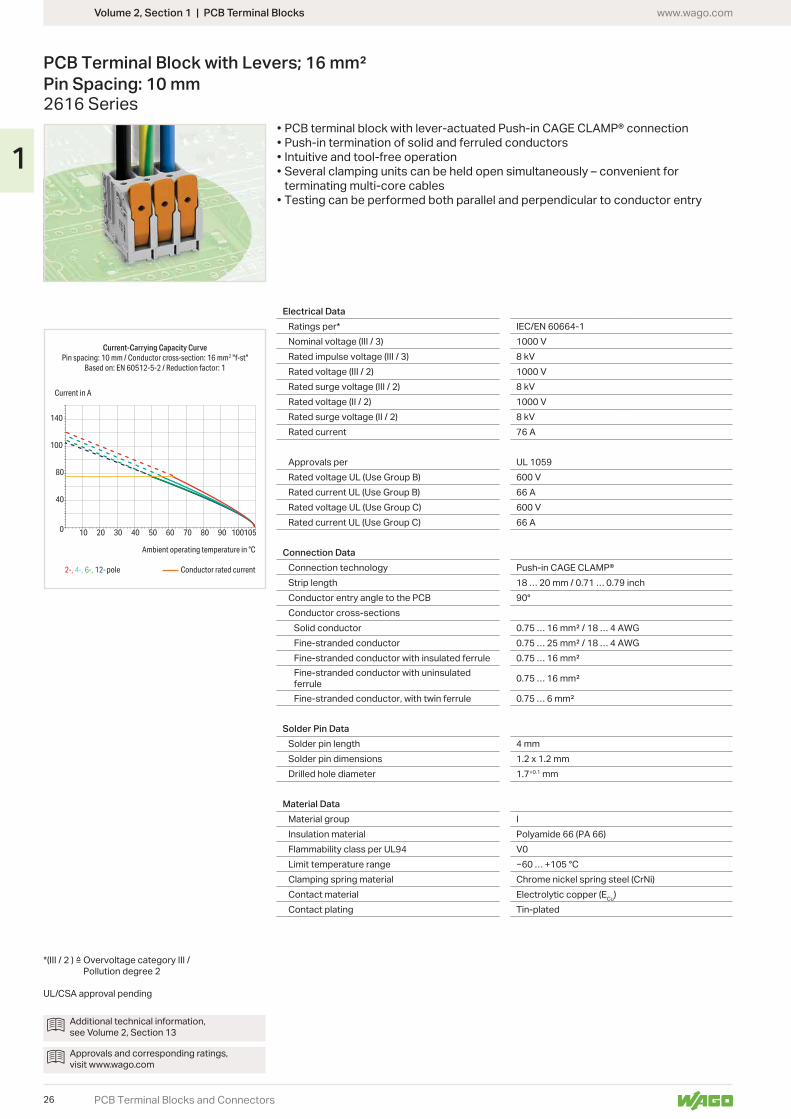
PCB Terminal Block with Levers; 16 mm² Pin Spacing: 10 mm2616 Series
Electrical DataRatings per* IEC/EN 60664-1Nominal voltage (III / 3) 1000 VRated impulse voltage (III / 3) 8 kVRated voltage (III / 2) 1000 VRated surge voltage (III / 2) 8 kVRated voltage (II / 2) 1000 VRated surge voltage (II / 2) 8 kVRated current 76 A
Approvals per UL 1059Rated voltage UL (Use Group B) 600 VRated current UL (Use Group B) 66 ARated voltage UL (Use Group C) 600 VRated current UL (Use Group C) 66 A
Connection DataConnection technology Push-in CAGE CLAMP®Strip length 18 … 20 mm / 0.71 … 0.79 inchConductor entry angle to the PCB 90°Conductor cross-sections
Solid conductorFine-stranded conductorFine-stranded conductor with insulated ferruleFine-stranded conductor with uninsulated ferruleFine-stranded conductor, with twin ferrule
Solder Pin DataSolder pin length 4 mmSolder pin dimensions 1.2 x 1.2 mmDrilled hole diameter 1.7+0.1 mm
Material DataMaterial group IInsulation material Polyamide 66 (PA 66)Flammability class per UL94 V0Limit temperature range … +105 °CClamping spring material Chrome nickel spring steel (CrNi)Contact material Electrolytic copper (ECu)Contact plating Tin-plated
Additional technical information, see Volume 2, Section 13
Approvals and corresponding ratings, visit www.wago.com
Pollution degree 2
UL/CSA approval pending
• PCB terminal block with lever-actuated Push-in CAGE CLAMP® connection• Push-in termination of solid and ferruled conductors• Intuitive and tool-free operation• Several clamping units can be held open simultaneously – convenient for
terminating multi-core cables• Testing can be performed both parallel and perpendicular to conductor entry
26
1
4
4
46
30 34,2
29,415
1,2
15
Ø 1,7
1,3 1,5
2,15
1,22,5
L
4
4
1,3
46
30 34,2
29,4
1,5
2,110 155
1,2 2,5 1,2
15
Ø 1,710 5
2,5
L
Volume 2, Section 1 | PCB Terminal Blockswww.wago.com
PCB Terminal Blocks and Connectors
PCB Terminal Block with Levers; 16 mm² Pin Spacing: 10 mm2616 Series
Dimensions (in mm): Dimensions (in mm):
PCB terminal block with lever; conductor entry perpendicular to PCB; 6 solder pins/pole; gray; 10 mm (0.394 inch) pin spacing
PCB terminal block with levers; conductor entry perpendicular to PCB; 3 staggered solder pins/pole; gray; 10 mm (0.394 inch) pin spacing
Pole No. Item No. Pack. Unit Pole No. Item No. Pack. Unit2616-3101 100 2616-3102/020-000 50
2616-3103/020-000 40
2616-3104/020-000 25
2616-3105/020-000 25
2616-3106/020-000 20
2616-3107/020-000 20
2616-3108/020-000 15
2616-3109/020-000 15
10 2616-3110/020-000 15
11 2616-3111/020-000 10
12 2616-3112/020-000 10
Available upon request (depending on quantity required):• Other pole numbers• Other colors• Other pin spacing• Direct marking
Insert solid conductors via push-in termination.
all conductors – via operating lever.
27
1
10 20 30 40 50 60 70 80 90 100 1050
20
30
40
10
2-, 4-, 6-, 12-
Current-Carrying Capacity CurvePin spacing: 5 mm / Conductor cross-section: 4 mm² "f-st"
Based on: EN 60512-5-2 / Reduction factor: 1
Current in A
Ambient operating temperature in °C
Conductor rated currentpole
Volume 2, Section 1 | PCB Terminal Blocks www.wago.com
PCB Terminal Blocks and Connectors
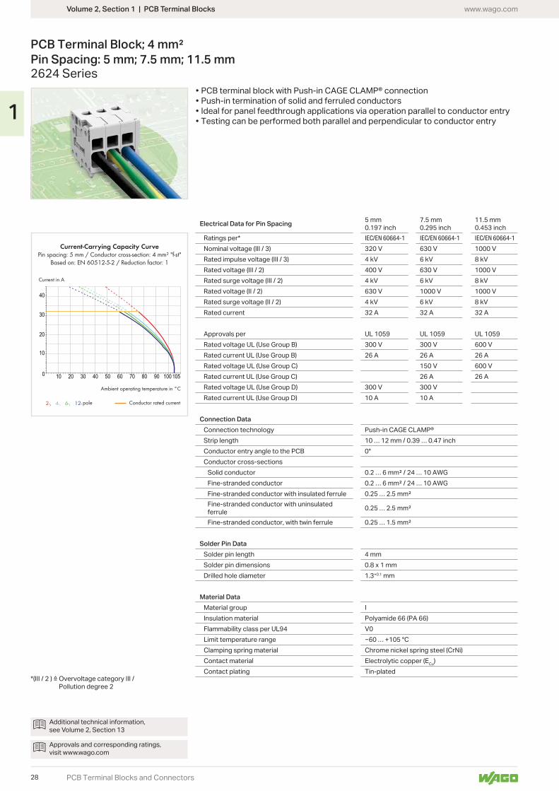
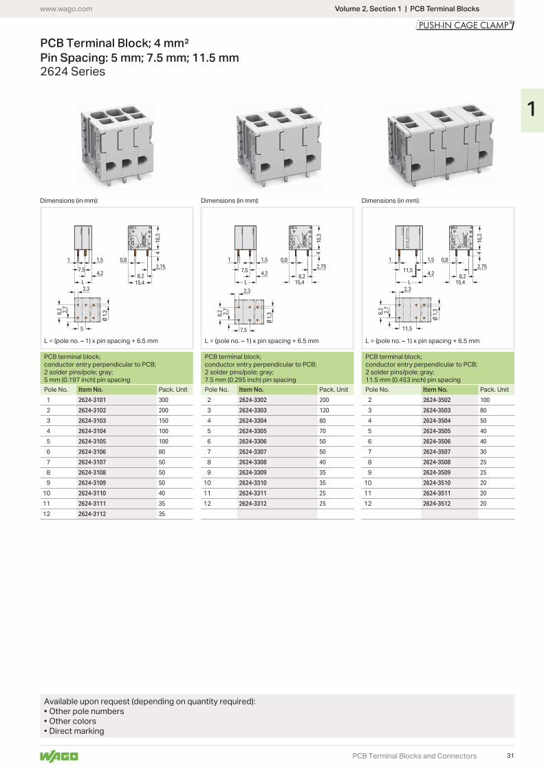
PCB Terminal Block; 4 mm² Pin Spacing: 5 mm; 7.5 mm; 11.5 mm2624 Series
Electrical Data for Pin Spacing 5 mm0.197 inch
7.5 mm 0.295 inch
11.5 mm0.453 inch
Ratings per* IEC/EN 60664-1 IEC/EN 60664-1 IEC/EN 60664-1
Nominal voltage (III / 3) 320 V 630 V 1000 VRated impulse voltage (III / 3) 4 kV 6 kV 8 kVRated voltage (III / 2) 400 V 630 V 1000 VRated surge voltage (III / 2) 4 kV 6 kV 8 kVRated voltage (II / 2) 630 V 1000 V 1000 VRated surge voltage (II / 2) 4 kV 6 kV 8 kVRated current 32 A 32 A 32 A
Approvals per UL 1059 UL 1059 UL 1059Rated voltage UL (Use Group B) 300 V 300 V 600 VRated current UL (Use Group B) 26 A 26 A 26 ARated voltage UL (Use Group C) 150 V 600 VRated current UL (Use Group C) 26 A 26 ARated voltage UL (Use Group D) 300 V 300 VRated current UL (Use Group D) 10 A 10 A
Connection DataConnection technology Push-in CAGE CLAMP®Strip length 10 … 12 mm / 0.39 … 0.47 inchConductor entry angle to the PCB 0°Conductor cross-sections
Solid conductorFine-stranded conductorFine-stranded conductor with insulated ferruleFine-stranded conductor with uninsulated ferruleFine-stranded conductor, with twin ferrule
Solder Pin DataSolder pin length 4 mmSolder pin dimensions 0.8 x 1 mmDrilled hole diameter 1.3+0.1 mm
Material DataMaterial group IInsulation material Polyamide 66 (PA 66)Flammability class per UL94 V0Limit temperature range … +105 °CClamping spring material Chrome nickel spring steel (CrNi)Contact material Electrolytic copper (ECu)Contact plating Tin-plated
• PCB terminal block with Push-in CAGE CLAMP® connection• Push-in termination of solid and ferruled conductors• Ideal for panel feedthrough applications via operation parallel to conductor entry• Testing can be performed both parallel and perpendicular to conductor entry
Additional technical information, see Volume 2, Section 13
Approvals and corresponding ratings, visit www.wago.com
Pollution degree 2
28
1
1,51
7,5 4,215
,44
0,8
8,2 5,616,3
8,2
2,3
2,55
Ø 1
,3
7,5
L
15,4
4
0,8
8,2 5,616,3
8,2
2,3
2,55
1,51
11,54,2
Ø 1
,3
11,5
L
1,5
15,4
1
5
4
4,2
0,8
8,2 5,616,3
Ø 1
,38,2
2,3
2,55
5
L
Volume 2, Section 1 | PCB Terminal Blockswww.wago.com
PCB Terminal Blocks and Connectors
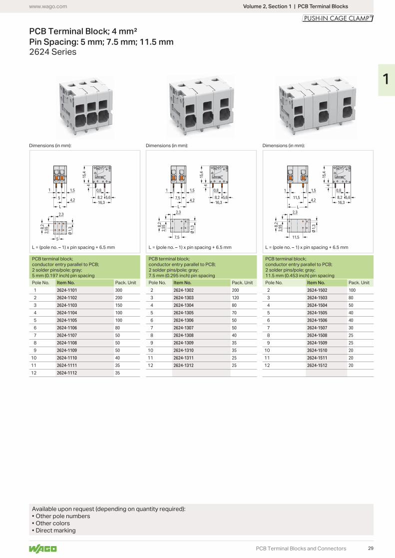
PCB Terminal Block; 4 mm² Pin Spacing: 5 mm; 7.5 mm; 11.5 mm2624 Series
Dimensions (in mm): Dimensions (in mm): Dimensions (in mm):
PCB terminal block; conductor entry parallel to PCB; 2 solder pins/pole; gray; 5 mm (0.197 inch) pin spacing
PCB terminal block; conductor entry parallel to PCB; 2 solder pins/pole; gray; 7.5 mm (0.295 inch) pin spacing
PCB terminal block; conductor entry parallel to PCB; 2 solder pins/pole; gray; 11.5 mm (0.453 inch) pin spacing
Pole No. Item No. Pack. Unit Pole No. Item No. Pack. Unit Pole No. Item No. Pack. Unit2624-1101 300 2624-1302 200 2624-1502 100
2624-1102 200 2624-1303 120 2624-1503 80
2624-1103 150 2624-1304 80 2624-1504 50
2624-1104 100 2624-1305 70 2624-1505 40
2624-1105 100 2624-1306 50 2624-1506 40
2624-1106 80 2624-1307 50 2624-1507 30
2624-1107 50 2624-1308 40 2624-1508 25
2624-1108 50 2624-1309 35 2624-1509 25
2624-1109 50 10 2624-1310 35 10 2624-1510 20
10 2624-1110 40 11 2624-1311 25 11 2624-1511 20
11 2624-1111 35 12 2624-1312 25 12 2624-1512 20
12 2624-1112 35
Available upon request (depending on quantity required):• Other pole numbers• Other colors• Direct marking
29
1
10 20 30 40 50 60 70 80 90 100 1050
20
30
40
10
2-, 4-, 6-, 12-
Current-Carrying Capacity CurvePin spacing: 5 mm / Conductor cross-section: 4 mm² "f-st"
Based on: EN 60512-5-2 / Reduction factor: 1
Current in A
Ambient operating temperature in °C
Conductor rated currentpole
Volume 2, Section 1 | PCB Terminal Blocks www.wago.com
PCB Terminal Blocks and Connectors
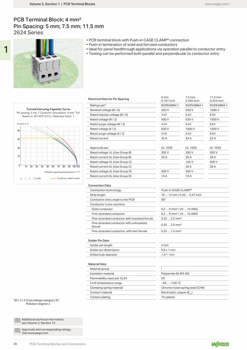
PCB Terminal Block; 4 mm² Pin Spacing: 5 mm; 7.5 mm; 11.5 mm2624 Series
Electrical Data for Pin Spacing 5 mm0.197 inch
7.5 mm 0.295 inch
11.5 mm0.453 inch
Ratings per* IEC/EN 60664-1 IEC/EN 60664-1 IEC/EN 60664-1
Nominal voltage (III / 3) 320 V 630 V 1000 VRated impulse voltage (III / 3) 4 kV 6 kV 8 kVRated voltage (III / 2) 400 V 630 V 1000 VRated surge voltage (III / 2) 4 kV 6 kV 8 kVRated voltage (II / 2) 630 V 1000 V 1000 VRated surge voltage (II / 2) 4 kV 6 kV 8 kVRated current 32 A 32 A 32 A
Approvals per UL 1059 UL 1059 UL 1059Rated voltage UL (Use Group B) 300 V 300 V 600 VRated current UL (Use Group B) 26 A 26 A 26 ARated voltage UL (Use Group C) 150 V 600 VRated current UL (Use Group C) 26 A 26 ARated voltage UL (Use Group D) 300 V 300 VRated current UL (Use Group D) 10 A 10 A
Connection DataConnection technology Push-in CAGE CLAMP®Strip length 10 … 12 mm / 0.39 … 0.47 inchConductor entry angle to the PCB 90°Conductor cross-sections
Solid conductorFine-stranded conductorFine-stranded conductor with insulated ferruleFine-stranded conductor with uninsulated ferruleFine-stranded conductor, with twin ferrule
Solder Pin DataSolder pin length 4 mmSolder pin dimensions 0.8 x 1 mmDrilled hole diameter 1.3+0.1 mm
Material DataMaterial group IInsulation material Polyamide 66 (PA 66)Flammability class per UL94 V0Limit temperature range … +105 °CClamping spring material Chrome nickel spring steel (CrNi)Contact material Electrolytic copper (ECu)Contact plating Tin-plated
Additional technical information, see Volume 2, Section 13
Approvals and corresponding ratings, visit www.wago.com
Pollution degree 2
• PCB terminal block with Push-in CAGE CLAMP® connection• Push-in termination of solid and ferruled conductors• Ideal for panel feedthrough applications via operation parallel to conductor entry• Testing can be performed both parallel and perpendicular to conductor entry
30
1
0,8
4
2,75
8,215,4
16,3
7,5
Ø 1
,3
2,3
8,2 2,7
1,51
7,5 4,2
L
1,51
11,5 4,2
0,82,75
8,215,4
11,5
Ø 1
,3
2,3
8,2 2,7
416
,3
L
Ø 1
,3
2,3
8,2 2,7
0,82,75
8,215,4
5
16,3
4
1,51
7,54,2
L
Volume 2, Section 1 | PCB Terminal Blockswww.wago.com
PCB Terminal Blocks and Connectors
PCB Terminal Block; 4 mm² Pin Spacing: 5 mm; 7.5 mm; 11.5 mm2624 Series
Dimensions (in mm): Dimensions (in mm): Dimensions (in mm):
PCB terminal block; conductor entry perpendicular to PCB; 2 solder pins/pole; gray; 5 mm (0.197 inch) pin spacing
PCB terminal block; conductor entry perpendicular to PCB; 2 solder pins/pole; gray; 7.5 mm (0.295 inch) pin spacing
PCB terminal block; conductor entry perpendicular to PCB; 2 solder pins/pole; gray; 11.5 mm (0.453 inch) pin spacing
Pole No. Item No. Pack. Unit Pole No. Item No. Pack. Unit Pole No. Item No. Pack. Unit2624-3101 300 2624-3302 200 2624-3502 100
2624-3102 200 2624-3303 120 2624-3503 80
2624-3103 150 2624-3304 80 2624-3504 50
2624-3104 100 2624-3305 70 2624-3505 40
2624-3105 100 2624-3306 50 2624-3506 40
2624-3106 80 2624-3307 50 2624-3507 30
2624-3107 50 2624-3308 40 2624-3508 25
2624-3108 50 2624-3309 35 2624-3509 25
2624-3109 50 10 2624-3310 35 10 2624-3510 20
10 2624-3110 40 11 2624-3311 25 11 2624-3511 20
11 2624-3111 35 12 2624-3312 25 12 2624-3512 20
12 2624-3112 35
Available upon request (depending on quantity required):• Other pole numbers• Other colors• Direct marking
31
1

10 20 30 40 50 60 70 80 90 1001050
20
40
60
80
2-, 4-, 6-, 12-
Current-Carrying Capacity CurvePin spacing: 7,5 mm / Conductor cross-section: 6 mm2 "f-st"
Based on: EN 60512-5-2 / Reduction factor: 1
Current in A
Ambient operating temperature in °C
Conductor rated currentpole
Volume 2, Section 1 | PCB Terminal Blocks www.wago.com
PCB Terminal Blocks and Connectors
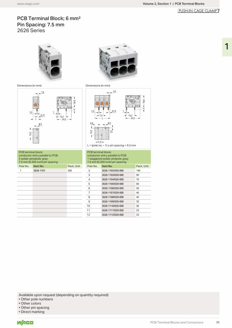
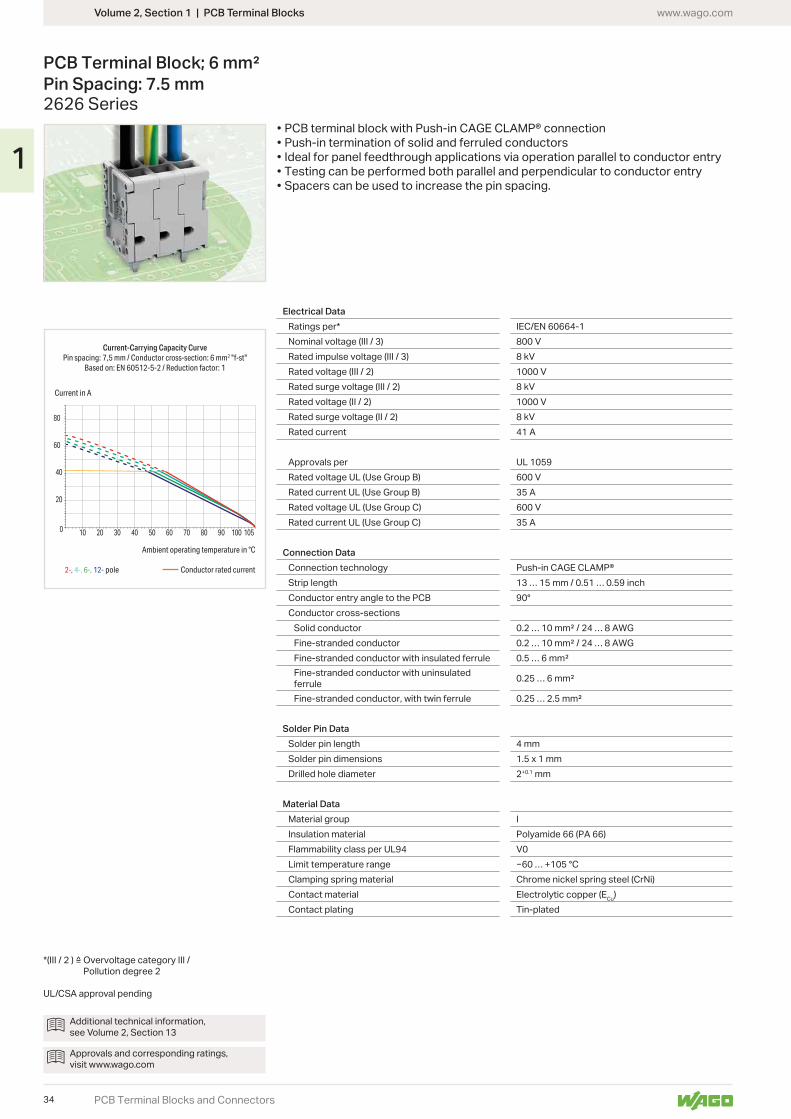
PCB Terminal Block; 6 mm² Pin Spacing: 7.5 mm2626 Series
Electrical DataRatings per* IEC/EN 60664-1Nominal voltage (III / 3) 800 VRated impulse voltage (III / 3) 8 kVRated voltage (III / 2) 1000 VRated surge voltage (III / 2) 8 kVRated voltage (II / 2) 1000 VRated surge voltage (II / 2) 8 kVRated current 41 A
Approvals per UL 1059Rated voltage UL (Use Group B) 600 VRated current UL (Use Group B) 35 ARated voltage UL (Use Group C) 600 VRated current UL (Use Group C) 35 A
Connection DataConnection technology Push-in CAGE CLAMP®Strip length 13 … 15 mm / 0.51 … 0.59 inchConductor entry angle to the PCB 0°Conductor cross-sections
Solid conductorFine-stranded conductorFine-stranded conductor with insulated ferruleFine-stranded conductor with uninsulated ferruleFine-stranded conductor, with twin ferrule
Solder Pin DataSolder pin length 4 mmSolder pin dimensionsDrilled hole diameter 2+0.1 mm
Material DataMaterial group IInsulation material Polyamide 66 (PA 66)Flammability class per UL94 V0Limit temperature range … +105 °CClamping spring material Chrome nickel spring steel (CrNi)Contact material Electrolytic copper (ECu)Contact plating Tin-plated
Additional technical information, see Volume 2, Section 13
Approvals and corresponding ratings, visit www.wago.com
Pollution degree 2
UL/CSA approval pending
• PCB terminal block with Push-in CAGE CLAMP® connection• Push-in termination of solid and ferruled conductors• Ideal for panel feedthrough applications via operation parallel to conductor entry• Testing can be performed both parallel and perpendicular to conductor entry• Spacers can be used to increase the pin spacing.
32
1
1,5(2,7)
13,2
1
1,8
24,213,2
416
,9
Ø 2
L
1,5
13,2
1,9
7,5
6,6
7,5
(2,7) 1
1,8
19,6
24,213,2
4
Ø 2
L
Volume 2, Section 1 | PCB Terminal Blockswww.wago.com
PCB Terminal Blocks and Connectors
PCB Terminal Block; 6 mm² Pin Spacing: 7.5 mm2626 Series
Dimensions (in mm): Dimensions (in mm):
PCB terminal block; conductor entry parallel to PCB; 2 solder pins/pole; gray; 7.5 mm (0.295 inch) pin spacing
PCB terminal block; conductor entry parallel to PCB; 1 staggered solder pin/pole; gray; 7.5 mm (0.295 inch) pin spacing
Pole No. Item No. Pack. Unit Pole No. Item No. Pack. Unit2626-1101 200 2626-1102/020-000 140
2626-1103/020-000 90
2626-1104/020-000 70
2626-1105/020-000 60
2626-1106/020-000 50
2626-1107/020-000 40
2626-1108/020-000 40
2626-1109/020-000 35
10 2626-1110/020-000 30
11 2626-1111/020-000 25
12 2626-1112/020-000 25
Available upon request (depending on quantity required):• Other pole numbers• Other colors• Other pin spacing• Direct marking
33
1
10 20 30 40 50 60 70 80 90 100 1050
20
40
60
80
2-, 4-, 6-, 12-
Current-Carrying Capacity CurvePin spacing: 7,5 mm / Conductor cross-section: 6 mm2 "f-st"
Based on: EN 60512-5-2 / Reduction factor: 1
Current in A
Ambient operating temperature in °C
Conductor rated currentpole
Volume 2, Section 1 | PCB Terminal Blocks www.wago.com
PCB Terminal Blocks and Connectors
PCB Terminal Block; 6 mm² Pin Spacing: 7.5 mm2626 Series
Electrical DataRatings per* IEC/EN 60664-1Nominal voltage (III / 3) 800 VRated impulse voltage (III / 3) 8 kVRated voltage (III / 2) 1000 VRated surge voltage (III / 2) 8 kVRated voltage (II / 2) 1000 VRated surge voltage (II / 2) 8 kVRated current 41 A
Approvals per UL 1059Rated voltage UL (Use Group B) 600 VRated current UL (Use Group B) 35 ARated voltage UL (Use Group C) 600 VRated current UL (Use Group C) 35 A
Connection DataConnection technology Push-in CAGE CLAMP®Strip length 13 … 15 mm / 0.51 … 0.59 inchConductor entry angle to the PCB 90°Conductor cross-sections
Solid conductorFine-stranded conductorFine-stranded conductor with insulated ferruleFine-stranded conductor with uninsulated ferruleFine-stranded conductor, with twin ferrule
Solder Pin DataSolder pin length 4 mmSolder pin dimensionsDrilled hole diameter 2+0.1 mm
Material DataMaterial group IInsulation material Polyamide 66 (PA 66)Flammability class per UL94 V0Limit temperature range … +105 °CClamping spring material Chrome nickel spring steel (CrNi)Contact material Electrolytic copper (ECu)Contact plating Tin-plated
Additional technical information, see Volume 2, Section 13
Approvals and corresponding ratings, visit www.wago.com
Pollution degree 2
UL/CSA approval pending
• PCB terminal block with Push-in CAGE CLAMP® connection• Push-in termination of solid and ferruled conductors• Ideal for panel feedthrough applications via operation parallel to conductor entry• Testing can be performed both parallel and perpendicular to conductor entry• Spacers can be used to increase the pin spacing.
34
1
1,8
1,5(2,7) 2,6
1
24,2
4
18,514
Ø 2
14
L
1,8
1,5
7,5
7,5
(2,7)
2,61
24,2
4
18,514
Ø 26,6
142,
6
L
Volume 2, Section 1 | PCB Terminal Blockswww.wago.com
PCB Terminal Blocks and Connectors
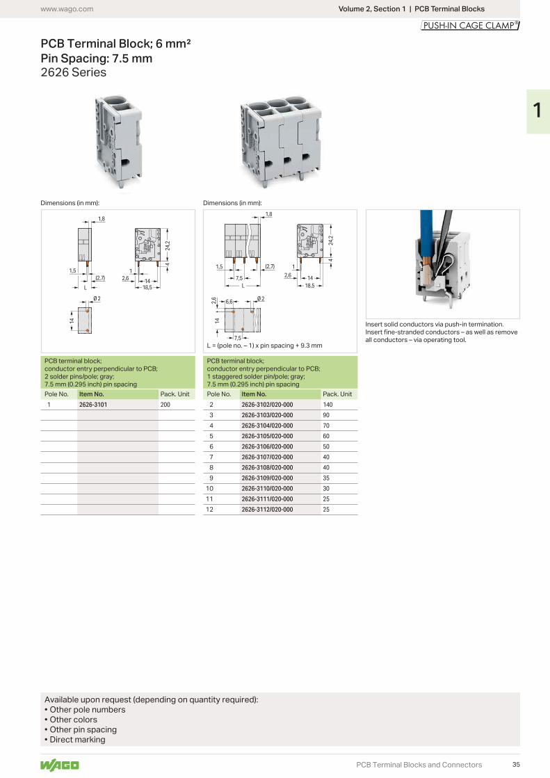
PCB Terminal Block; 6 mm² Pin Spacing: 7.5 mm2626 Series
Dimensions (in mm): Dimensions (in mm):
PCB terminal block; conductor entry perpendicular to PCB; 2 solder pins/pole; gray; 7.5 mm (0.295 inch) pin spacing
PCB terminal block; conductor entry perpendicular to PCB; 1 staggered solder pin/pole; gray; 7.5 mm (0.295 inch) pin spacing
Pole No. Item No. Pack. Unit Pole No. Item No. Pack. Unit2626-3101 200 2626-3102/020-000 140
2626-3103/020-000 90
2626-3104/020-000 70
2626-3105/020-000 60
2626-3106/020-000 50
2626-3107/020-000 40
2626-3108/020-000 40
2626-3109/020-000 35
10 2626-3110/020-000 30
11 2626-3111/020-000 25
12 2626-3112/020-000 25
Available upon request (depending on quantity required):• Other pole numbers• Other colors• Other pin spacing• Direct marking
Insert solid conductors via push-in termination.
all conductors – via operating tool.
35
1
10 20 30 40 50 60 70 80 90 1001050
40
80
100
140
2-, 4-, 6-, 12-
Current-Carrying Capacity CurvePin spacing: 10 mm / Conductor cross-section: 16 mm2 "f-st"
Based on: EN 60512-5-2 / Reduction factor: 1
Current in A
pole Conductor rated current
Ambient operating temperature in °C
Volume 2, Section 1 | PCB Terminal Blocks www.wago.com
PCB Terminal Blocks and Connectors
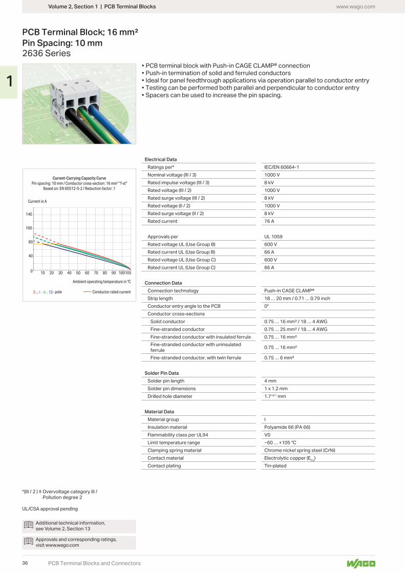
PCB Terminal Block; 16 mm² Pin Spacing: 10 mm2636 Series
Electrical Data Ratings per* IEC/EN 60664-1Nominal voltage (III / 3) 1000 VRated impulse voltage (III / 3) 8 kVRated voltage (III / 2) 1000 VRated surge voltage (III / 2) 8 kVRated voltage (II / 2) 1000 VRated surge voltage (II / 2) 8 kVRated current 76 A
Approvals per UL 1059Rated voltage UL (Use Group B) 600 VRated current UL (Use Group B) 66 ARated voltage UL (Use Group C) 600 VRated current UL (Use Group C) 66 A
Connection DataConnection technology Push-in CAGE CLAMP®Strip length 18 … 20 mm / 0.71 … 0.79 inchConductor entry angle to the PCB 0°Conductor cross-sections
Solid conductorFine-stranded conductorFine-stranded conductor with insulated ferruleFine-stranded conductor with uninsulated ferruleFine-stranded conductor, with twin ferrule
Solder Pin DataSolder pin length 4 mmSolder pin dimensionsDrilled hole diameter 1.7+0.1 mm
Material DataMaterial group IInsulation material Polyamide 66 (PA 66)Flammability class per UL94 V0Limit temperature range … +105 °CClamping spring material Chrome nickel spring steel (CrNi)Contact material Electrolytic copper (ECu)Contact plating Tin-plated
Additional technical information, see Volume 2, Section 13
Approvals and corresponding ratings, visit www.wago.com
Pollution degree 2
UL/CSA approval pending
• PCB terminal block with Push-in CAGE CLAMP® connection• Push-in termination of solid and ferruled conductors• Ideal for panel feedthrough applications via operation parallel to conductor entry• Testing can be performed both parallel and perpendicular to conductor entry• Spacers can be used to increase the pin spacing.
36
1
Ø 1,7
5 2,33
1,22,5 15 11,5
1
4
29,1
28,6
15
L Ø 1,74,3
10 5
2,5
2,615
5
1,6
2,3310
1,22,5 15 11,5
1
4
29,1
28,6
L
Volume 2, Section 1 | PCB Terminal Blockswww.wago.com
PCB Terminal Blocks and Connectors
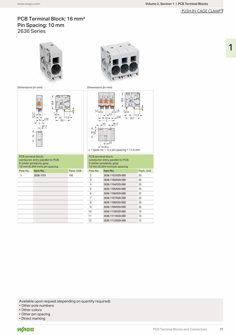
PCB Terminal Block; 16 mm² Pin Spacing: 10 mm2636 Series
Dimensions (in mm): Dimensions (in mm):
PCB terminal block; conductor entry parallel to PCB; 6 solder pins/pole; gray; 10 mm (0.394 inch) pin spacing
PCB terminal block; conductor entry parallel to PCB; 3 solder pins/pole; gray; 10 mm (0.394 inch) pin spacing
Pole No. Item No. Pack. Unit Pole No. Item No. Pack. Unit2636-1101 100 2636-1102/020-000 50
2636-1103/020-000 50
2636-1104/020-000 25
2636-1105/020-000 25
2636-1106/020-000 25
2636-1107/020-000 20
2636-1108/020-000 20
2636-1109/020-000 20
10 2636-1110/020-000 15
11 2636-1111/020-000 15
12 2636-1112/020-000 15
Available upon request (depending on quantity required):• Other pole numbers• Other colors• Other pin spacing• Direct marking
37
1
10 20 30 40 50 60 70 80 90 1001050
40
80
100
140
2-, 4-, 6-, 12-
Current-Carrying Capacity CurvePin spacing: 10 mm / Conductor cross-section: 16 mm2 "f-st"
Based on: EN 60512-5-2 / Reduction factor: 1
Current in A
pole
Ambient operating temperature in °C
Conductor rated current
Volume 2, Section 1 | PCB Terminal Blocks www.wago.com
PCB Terminal Blocks and Connectors
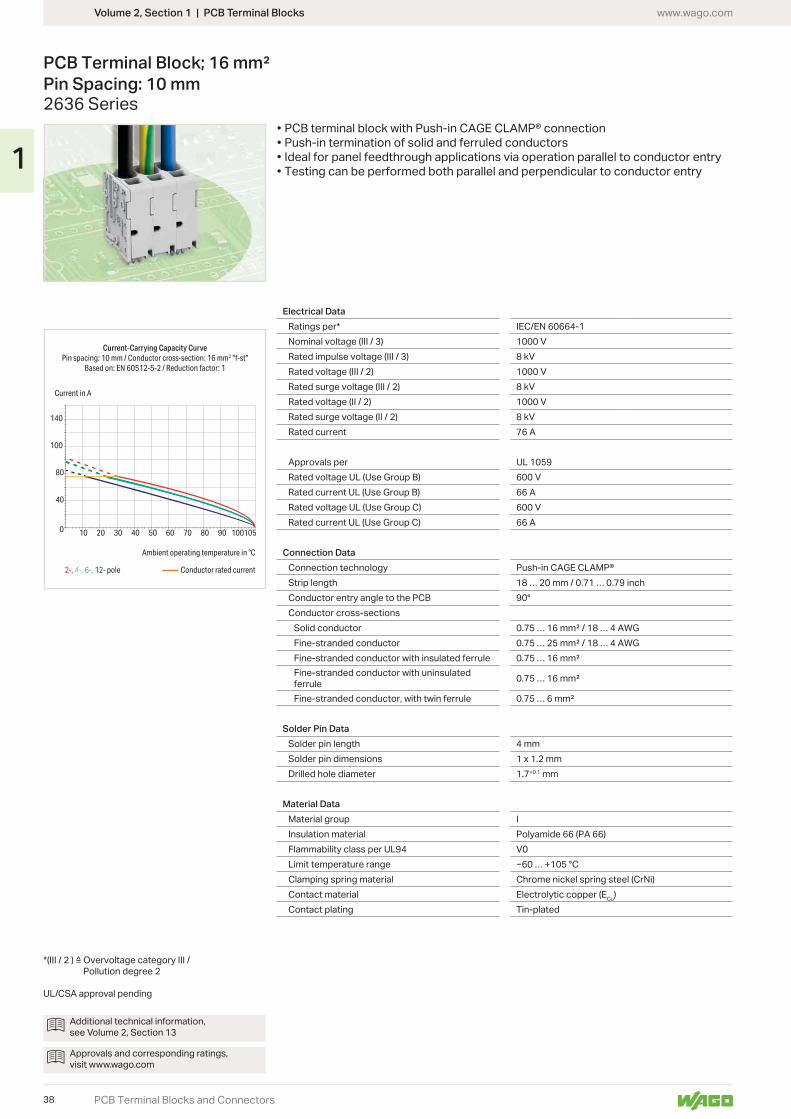
PCB Terminal Block; 16 mm² Pin Spacing: 10 mm2636 Series
Electrical DataRatings per* IEC/EN 60664-1Nominal voltage (III / 3) 1000 VRated impulse voltage (III / 3) 8 kVRated voltage (III / 2) 1000 VRated surge voltage (III / 2) 8 kVRated voltage (II / 2) 1000 VRated surge voltage (II / 2) 8 kVRated current 76 A
Approvals per UL 1059Rated voltage UL (Use Group B) 600 VRated current UL (Use Group B) 66 ARated voltage UL (Use Group C) 600 VRated current UL (Use Group C) 66 A
Connection DataConnection technology Push-in CAGE CLAMP®Strip length 18 … 20 mm / 0.71 … 0.79 inchConductor entry angle to the PCB 90°Conductor cross-sections
Solid conductorFine-stranded conductorFine-stranded conductor with insulated ferruleFine-stranded conductor with uninsulated ferruleFine-stranded conductor, with twin ferrule
Solder Pin DataSolder pin length 4 mmSolder pin dimensionsDrilled hole diameter 1.7+0.1 mm
Material DataMaterial group IInsulation material Polyamide 66 (PA 66)Flammability class per UL94 V0Limit temperature range … +105 °CClamping spring material Chrome nickel spring steel (CrNi)Contact material Electrolytic copper (ECu)Contact plating Tin-plated
Additional technical information, see Volume 2, Section 13
Approvals and corresponding ratings, visit www.wago.com
Pollution degree 2
UL/CSA approval pending
• PCB terminal block with Push-in CAGE CLAMP® connection• Push-in termination of solid and ferruled conductors• Ideal for panel feedthrough applications via operation parallel to conductor entry• Testing can be performed both parallel and perpendicular to conductor entry
38
1
1,2
2,335
2,5
31,3
3,95
15
1
24,8
Ø 1,7
15
L
1,2
10 5
2,332,5
Ø 1,7
15
10 5
2,531
,3
3,95
15
1
24,8L
Volume 2, Section 1 | PCB Terminal Blockswww.wago.com
PCB Terminal Blocks and Connectors
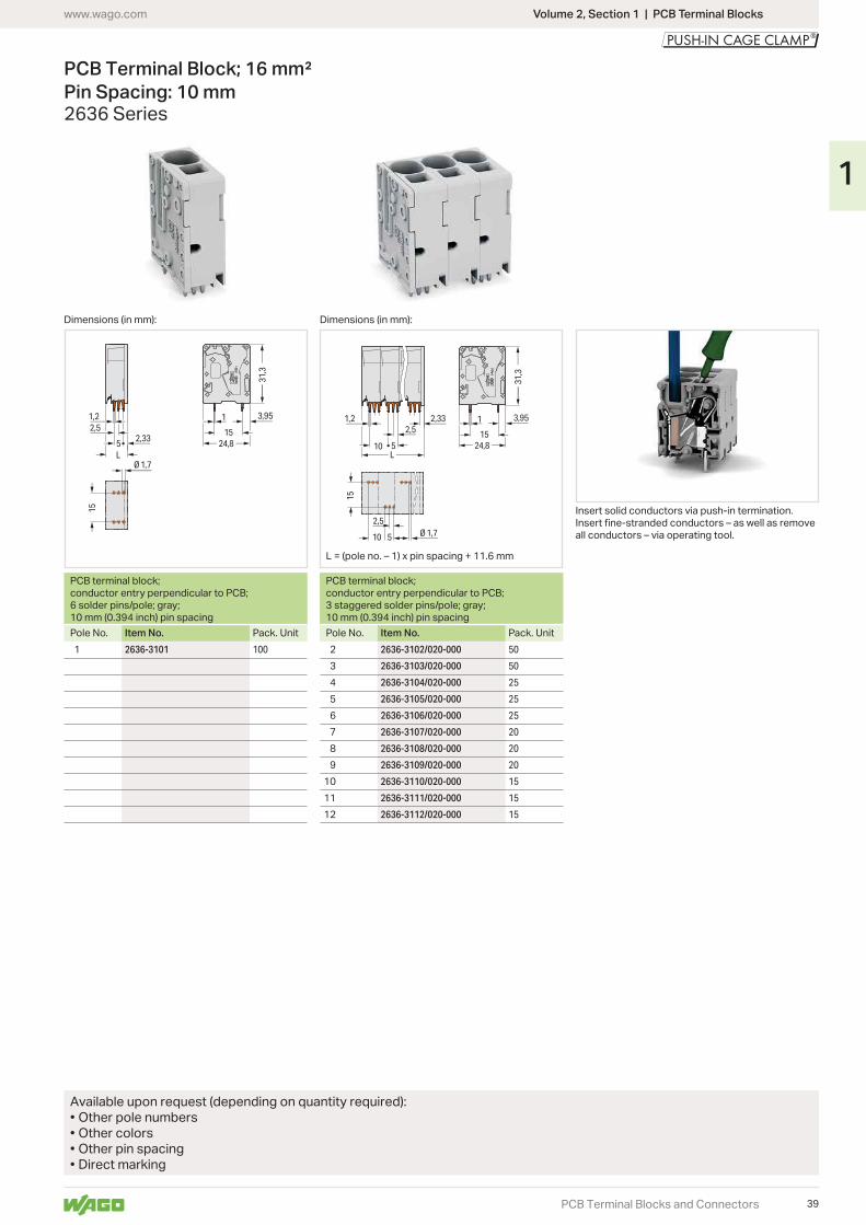
PCB Terminal Block; 16 mm² Pin Spacing: 10 mm2636 Series
Dimensions (in mm): Dimensions (in mm):
PCB terminal block; conductor entry perpendicular to PCB; 6 solder pins/pole; gray; 10 mm (0.394 inch) pin spacing
PCB terminal block; conductor entry perpendicular to PCB; 3 staggered solder pins/pole; gray; 10 mm (0.394 inch) pin spacing
Pole No. Item No. Pack. Unit Pole No. Item No. Pack. Unit2636-3101 100 2636-3102/020-000 50
2636-3103/020-000 50
2636-3104/020-000 25
2636-3105/020-000 25
2636-3106/020-000 25
2636-3107/020-000 20
2636-3108/020-000 20
2636-3109/020-000 20
10 2636-3110/020-000 15
11 2636-3111/020-000 15
12 2636-3112/020-000 15
Available upon request (depending on quantity required):• Other pole numbers• Other colors• Other pin spacing• Direct marking
Insert solid conductors via push-in termination.
all conductors – via operating tool.
39
1

Volume 2, Section 2 | SMD PCB Terminal Blocks www.wago.com
PCB Terminal Blocks and Pluggable Connectors
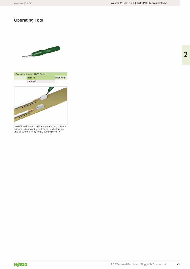
Through-Board SMD PCB Terminal Block; 0.75 mm²Pin Spacing: 6.5 mm 2070 Series
• SMD PCB terminal block with Push-in CAGE CLAMP® connection for back-side wir-ing of LED modules
• Low profile of just 1.1 mm on the module’s front side• Connect solid conductors via push-in termination• Insert fine-stranded conductors and remove all conductors via operating tool
Clearance and creepage distances >=3.0 mm: 500 V in applications per EN 60598-1
Pollution degree 2
Electrical Data for FR4 PCB TypeRatings per* IEC/EN 60664-1Nominal voltage (III / 3) 320 VRated surge voltage (III / 3) 4 kVRated voltage (III / 2) 320 VRated surge voltage (III / 2) 4 kVNominal voltage (II / 2) 630 VRated surge voltage (II / 2) 4 kVRated current 9 A
Electrical Data for Metal-Core PCBsRatings per* IEC/EN 60664-1Nominal voltage (III / 3) 200 VRated surge voltage (III / 3) 4 kVRated voltage (III / 2) 320 VRated surge voltage (III / 2) 4 kVNominal voltage (II / 2) 500 VRated surge voltage (II / 2) 4 kVRated current 9 A
Approvals per UL 1977Rated voltage UL 600 VRated current UL 9 A
Connection DataConnection technology Push-in CAGE CLAMP®Strip length 8.5 … 10 mm / 0.345 … 0.395 inchConductor entry angle to the PCB 0°Conductor range
Solid conductorFine-stranded conductor
Material DataMaterial group IInsulation material Polyphthalamide (PPA GF)Flammability class per UL94 V0Limit temperature range … +105 °CContact material Copper alloyContact plating Tin-plated
Operating tool see page 57
Additional technical information, see Volume 2, Section 13
Approvals and corresponding ratings, visit www.wago.com
40
2
3,3
7,4
5,34
3,3
4,4
3,5
19,62
13
0,95
6,455°4,
3
12,6
18,422,2
3,1
max. R1
8
0,4
23,5
23,544
8,9
R
7,45
11,810,5
6,5
10,93,
5
19,62
6,5
3,1 3,33,3 13
0,95
6,455°4,
3
12,6
18,422,2
max. R1
16
0,4
23,5
23,5
448,
9
R
24
0,4
23,5 23
,544
8,9
R
6,5
7,45
18,317
6,5
3,33,3
17,4
3,5
19,62
13
6,5
3,1
0,95
6,455°4,
3
12,6
18,422,2
max. R1
Volume 2, Section 2 | SMD PCB Terminal Blockswww.wago.com
PCB Terminal Blocks and Pluggable Connectors
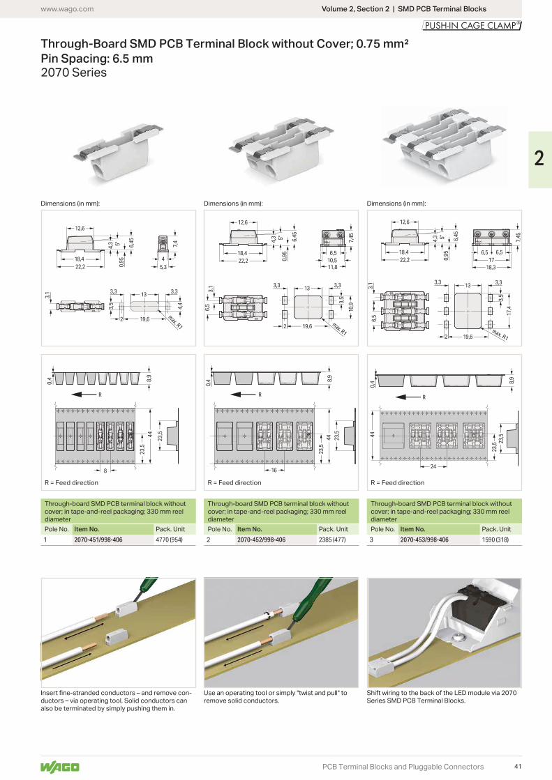
Through-Board SMD PCB Terminal Block without Cover; 0.75 mm² Pin Spacing: 6.5 mm2070 Series
Dimensions (in mm): Dimensions (in mm): Dimensions (in mm):
R = Feed directionR = Feed directionR = Feed direction
Through-board SMD PCB terminal block without cover; in tape-and-reel packaging; 330 mm reel diameter
Through-board SMD PCB terminal block without cover; in tape-and-reel packaging; 330 mm reel diameter
Through-board SMD PCB terminal block without cover; in tape-and-reel packaging; 330 mm reel diameter
Pole No. Item No. Pack. Unit Pole No. Item No. Pack. Unit Pole No. Item No. Pack. Unit1 2070-451/998-406 4770 (954) 2 2070-452/998-406 2385 (477) 3 2070-453/998-406 1590 (318)
-ductors – via operating tool. Solid conductors can also be terminated by simply pushing them in.
Use an operating tool or simply "twist and pull" to remove solid conductors.
Shift wiring to the back of the LED module via 2070 Series SMD PCB Terminal Blocks.
41
2
3,3
7,4
5,34
3,3
4,4
3,5
19,62
13
0,95
6,455°4,
3
12,6
18,422,2
3,1
max. R1
0,4
21,9
5
23,544
8,9
8
R
max. R1
0,95
6,455°4,
3
12,6
18,422,2
3,1
6,5
10,93,
519,62
3,33,3 13
7,45
11,810,5
6,5
16
0,4
21,9
5
23,5
448,
9
R
24
0,4
21,9
5 23,544
8,9
R
0,95
6,455°4,
3
12,6
18,422,2
6,5
3,1
18,3
3,33,3
17,4
3,5
19,62
13
6,5
7,45
18,317
6,5
max. R1
Volume 2, Section 2 | SMD PCB Terminal Blocks www.wago.com
PCB Terminal Blocks and Pluggable Connectors
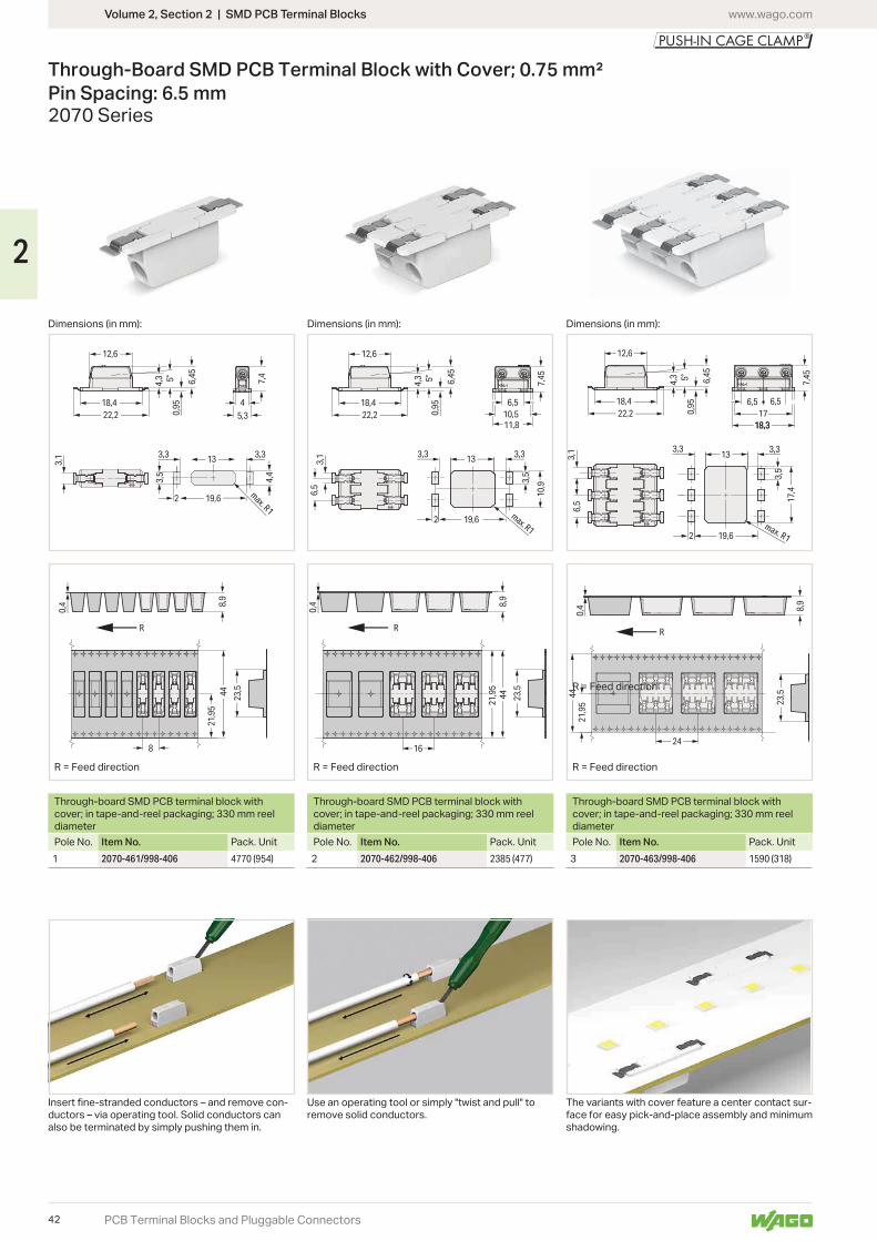
Through-Board SMD PCB Terminal Block with Cover; 0.75 mm² Pin Spacing: 6.5 mm2070 Series
Dimensions (in mm): Dimensions (in mm): Dimensions (in mm):
R = Feed direction
R = Feed direction R = Feed directionR = Feed direction
Through-board SMD PCB terminal block with cover; in tape-and-reel packaging; 330 mm reel diameter
Through-board SMD PCB terminal block with cover; in tape-and-reel packaging; 330 mm reel diameter
Through-board SMD PCB terminal block with cover; in tape-and-reel packaging; 330 mm reel diameter
Pole No. Item No. Pack. Unit Pole No. Item No. Pack. Unit Pole No. Item No. Pack. Unit1 2070-461/998-406 4770 (954) 2 2070-462/998-406 2385 (477) 3 2070-463/998-406 1590 (318)
-ductors – via operating tool. Solid conductors can also be terminated by simply pushing them in.
Use an operating tool or simply "twist and pull" to remove solid conductors.
The variants with cover feature a center contact sur-face for easy pick-and-place assembly and minimum shadowing.
42
2
3,3
7,4
5,34
3,3
4,4
3,5
19,62
13
0,95
6,455°4,
3
12,6
18,422,2
3,1
max. R1
0,4
21,9
5
23,544
8,9
8
R
max. R1
0,95
6,455°4,
3
12,6
18,422,2
3,1
6,5
10,93,
5
19,62
3,33,3 13
7,45
11,810,5
6,5
16
0,4
21,9
5
23,5
448,
9
R
24
0,4
21,9
5 23,544
8,9
R
0,95
6,455°4,
3
12,6
18,422,2
6,5
3,1
18,3
3,33,3
17,4
3,5
19,62
13
6,5
7,45
18,317
6,5
max. R1
Volume 2, Section 2 | SMD PCB Terminal Blockswww.wago.com
PCB Terminal Blocks and Pluggable Connectors
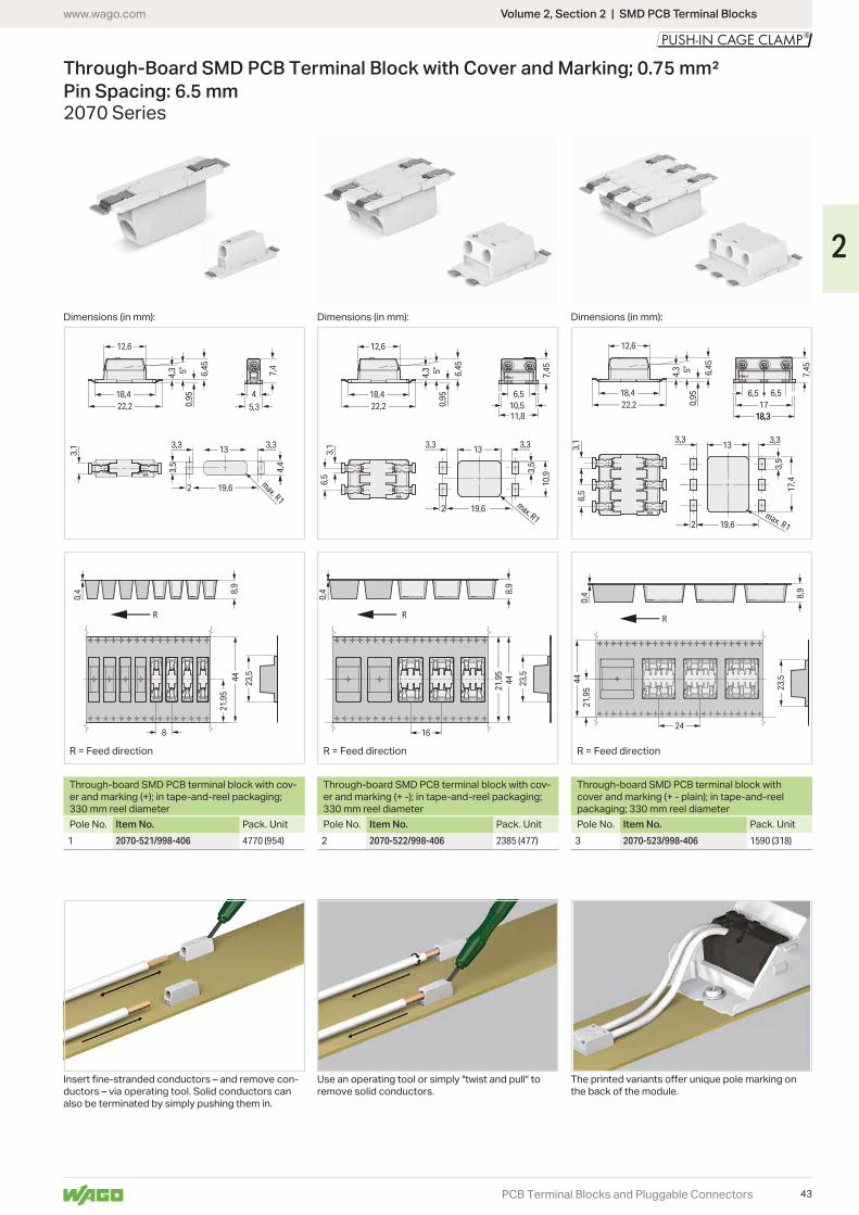
Through-Board SMD PCB Terminal Block with Cover and Marking; 0.75 mm² Pin Spacing: 6.5 mm2070 Series
Dimensions (in mm): Dimensions (in mm): Dimensions (in mm):
R = Feed directionR = Feed directionR = Feed direction
Through-board SMD PCB terminal block with cov-er and marking (+); in tape-and-reel packaging; 330 mm reel diameter
Through-board SMD PCB terminal block with cov-er and marking (+ -); in tape-and-reel packaging; 330 mm reel diameter
Through-board SMD PCB terminal block with cover and marking (+ - plain); in tape-and-reel packaging; 330 mm reel diameter
Pole No. Item No. Pack. Unit Pole No. Item No. Pack. Unit Pole No. Item No. Pack. Unit1 2070-521/998-406 4770 (954) 2 2070-522/998-406 2385 (477) 3 2070-523/998-406 1590 (318)
-ductors – via operating tool. Solid conductors can also be terminated by simply pushing them in.
Use an operating tool or simply "twist and pull" to remove solid conductors. the back of the module.
43
2
3,3
7,4
5,34
3,3
4,4
3,5
19,62
13
0,95
6,455°4,
3
12,6
18,422,2
3,1
max. R1
0,4
21,9
5
23,544
8,9
8
R
max. R1
0,95
6,455°4,
3
12,6
18,422,2
3,1
6,5
10,93,
519,62
3,33,3 13
7,45
11,810,5
6,5
16
0,4
21,9
5
23,5
448,
9
R
24
0,4
21,9
5 23,544
8,9
R
0,95
6,455°4,
3
12,6
18,422,2
6,5
3,1
18,3
3,33,3
17,4
3,5
19,62
13
6,5
7,45
18,317
6,5
max. R1
Volume 2, Section 2 | SMD PCB Terminal Blocks www.wago.com
PCB Terminal Blocks and Pluggable Connectors
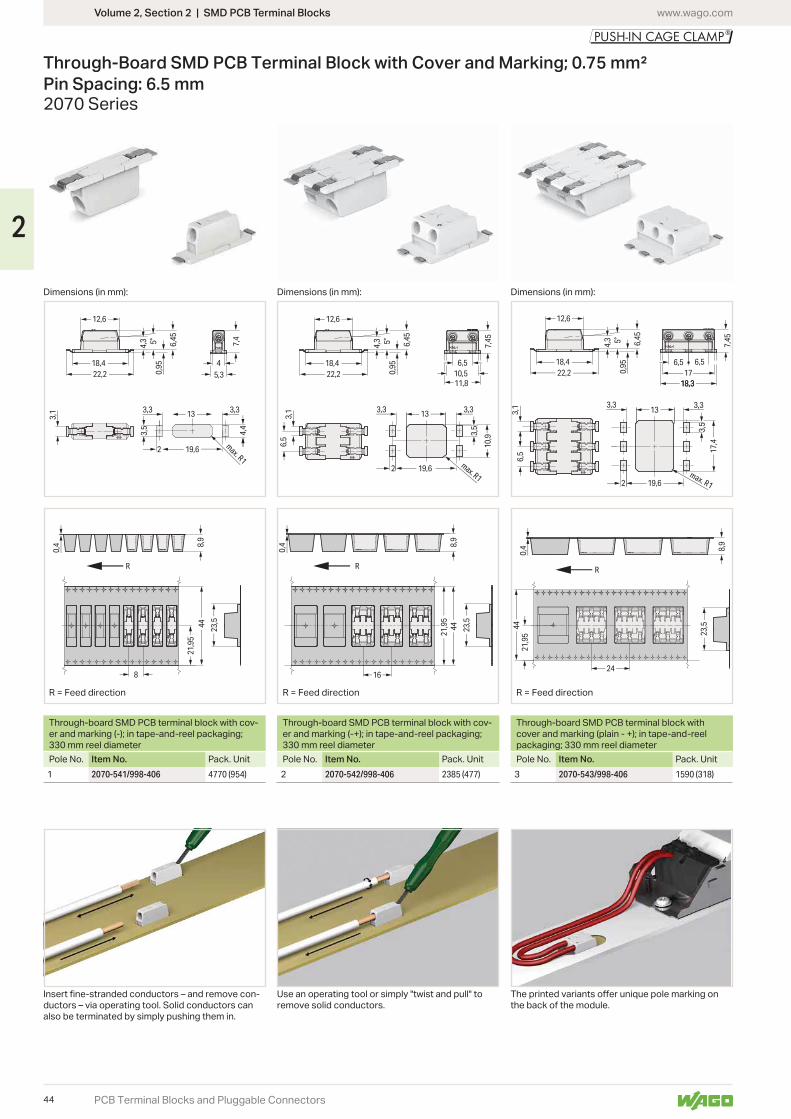
Through-Board SMD PCB Terminal Block with Cover and Marking; 0.75 mm² Pin Spacing: 6.5 mm2070 Series
Dimensions (in mm): Dimensions (in mm): Dimensions (in mm):
R = Feed directionR = Feed directionR = Feed direction
Through-board SMD PCB terminal block with cov-er and marking (-); in tape-and-reel packaging; 330 mm reel diameter
Through-board SMD PCB terminal block with cov-er and marking (-+); in tape-and-reel packaging; 330 mm reel diameter
Through-board SMD PCB terminal block with cover and marking (plain - +); in tape-and-reel packaging; 330 mm reel diameter
Pole No. Item No. Pack. Unit Pole No. Item No. Pack. Unit Pole No. Item No. Pack. Unit1 2070-541/998-406 4770 (954) 2 2070-542/998-406 2385 (477) 3 2070-543/998-406 1590 (318)
-ductors – via operating tool. Solid conductors can also be terminated by simply pushing them in.
Use an operating tool or simply "twist and pull" to remove solid conductors. the back of the module.
44
2
Volume 2, Section 2 | SMD PCB Terminal Blockswww.wago.com
PCB Terminal Blocks and Pluggable Connectors
Operating Tool
Operating tool for 2070 SeriesItem No. Pack. Unit2070-400 1
-ductors – via operating tool. Solid conductors can also be terminated by simply pushing them in.
45
2
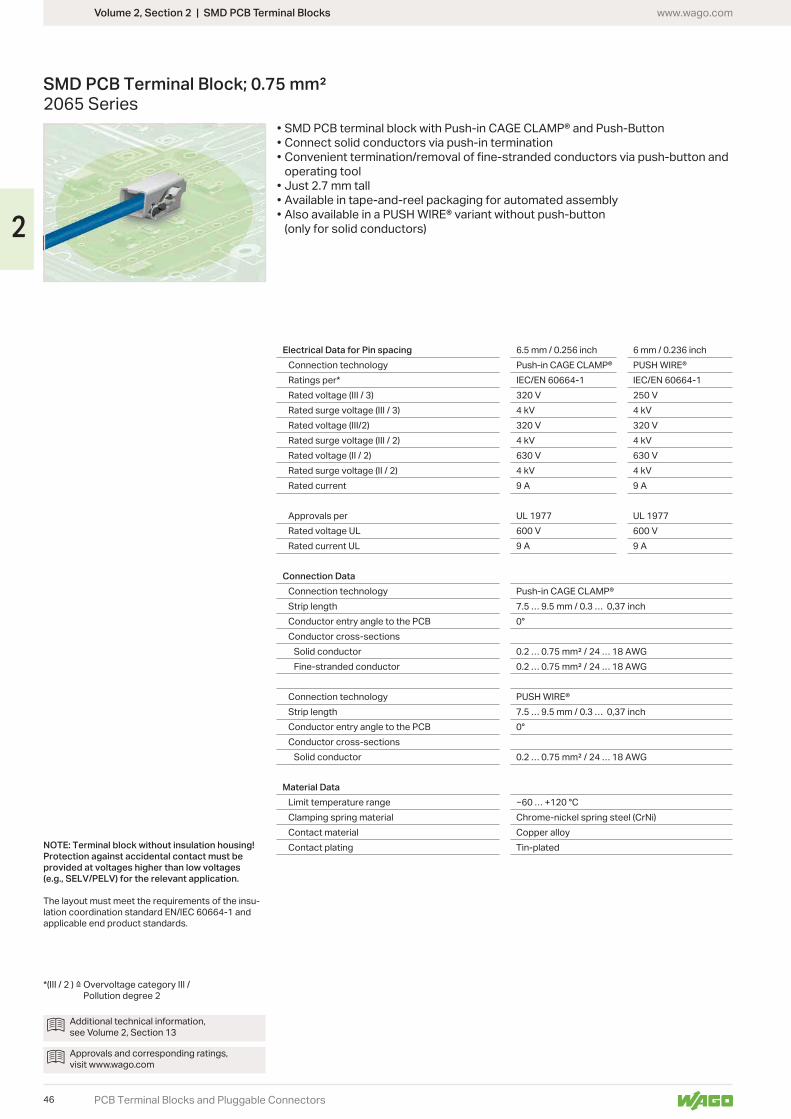
Volume 2, Section 2 | SMD PCB Terminal Blocks www.wago.com
PCB Terminal Blocks and Pluggable Connectors
SMD PCB Terminal Block; 0.75 mm² 2065 Series
• SMD PCB terminal block with Push-in CAGE CLAMP® and Push-Button• Connect solid conductors via push-in termination• Convenient termination/removal of fine-stranded conductors via push-button and
operating tool• Just 2.7 mm tall• Available in tape-and-reel packaging for automated assembly•
(only for solid conductors)
NOTE: Terminal block without insulation housing! Protection against accidental contact must be provided at voltages higher than low voltages (e.g., SELV/PELV) for the relevant application.
The layout must meet the requirements of the insu-lation coordination standard EN/IEC 60664-1 and applicable end product standards.
Pollution degree 2
Electrical Data for Pin spacing 6.5 mm / 0.256 inch 6 mm / 0.236 inchConnection technology Push-in CAGE CLAMP®Ratings per* IEC/EN 60664-1 IEC/EN 60664-1Rated voltage (III / 3) 320 V 250 VRated surge voltage (III / 3) 4 kV 4 kVRated voltage (III/2) 320 V 320 VRated surge voltage (III / 2) 4 kV 4 kVRated voltage (II / 2) 630 V 630 VRated surge voltage (II / 2) 4 kV 4 kVRated current 9 A 9 A
Approvals per UL 1977 UL 1977Rated voltage UL 600 V 600 VRated current UL 9 A 9 A
Connection DataConnection technology Push-in CAGE CLAMP®Strip length 7.5 … 9.5 mm / 0.3 … 0,37 inchConductor entry angle to the PCB 0°Conductor cross-sections
Solid conductorFine-stranded conductor
Connection technologyStrip length 7.5 … 9.5 mm / 0.3 … 0,37 inchConductor entry angle to the PCB 0°Conductor cross-sections
Solid conductor
Material DataLimit temperature range … +120 °CClamping spring material Chrome-nickel spring steel (CrNi)Contact material Copper alloyContact plating Tin-plated
Additional technical information, see Volume 2, Section 13
Approvals and corresponding ratings, visit www.wago.com
46
2
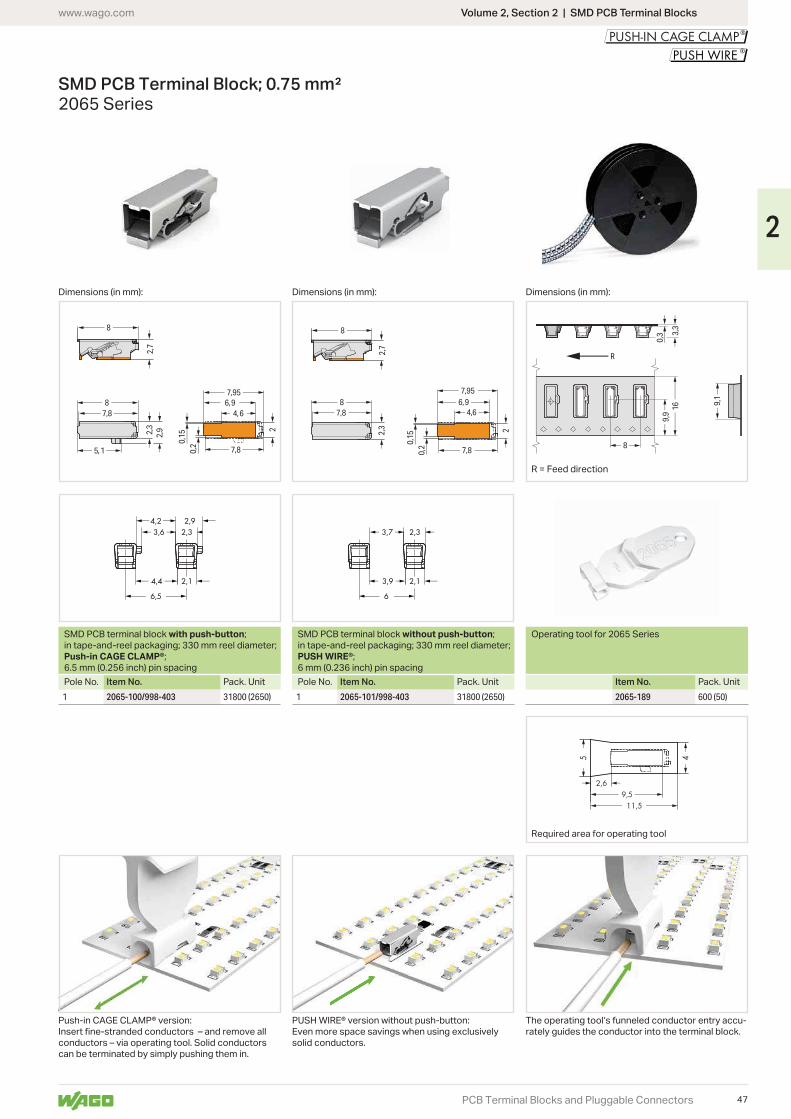
2,7
8
87,8
2,3 2
0,20,
152,9
5,1
4,6
7,8
6,97,95
6,5<___ ___>
4,4 2,1<_ <__>
4,2 2,9<_ <__>
3,6 2,3< (>
2,7
8
87,8
2,3 2
0,20,
154,6
7,8
6,97,95
6<___ ___>
3,9 2,1< <_>
3,7< > 2,3 <
<>
5
<>
4
11,5<______ <______
9,5<_____ <_____
2,6 <<
3,3
0,3
9,1
9,9
16
8
R
Volume 2, Section 2 | SMD PCB Terminal Blockswww.wago.com
PCB Terminal Blocks and Pluggable Connectors
SMD PCB Terminal Block; 0.75 mm² 2065 Series
Dimensions (in mm): Dimensions (in mm): Dimensions (in mm):
R = Feed direction
SMD PCB terminal block with push-button; in tape-and-reel packaging; 330 mm reel diameter; Push-in CAGE CLAMP®; 6.5 mm (0.256 inch) pin spacing
SMD PCB terminal block without push-button; in tape-and-reel packaging; 330 mm reel diameter; PUSH WIRE®; 6 mm (0.236 inch) pin spacing
Operating tool for 2065 Series
Pole No. Item No. Pack. Unit Pole No. Item No. Pack. Unit Item No. Pack. Unit1 2065-100/998-403 31800 (2650) 1 2065-101/998-403 31800 (2650) 2065-189 600 (50)
Even more space savings when using exclusively solid conductors.
Push-in CAGE CLAMP® version:
conductors – via operating tool. Solid conductors can be terminated by simply pushing them in.
The operating tool‘s funneled conductor entry accu-rately guides the conductor into the terminal block.
Required area for operating tool
47
2
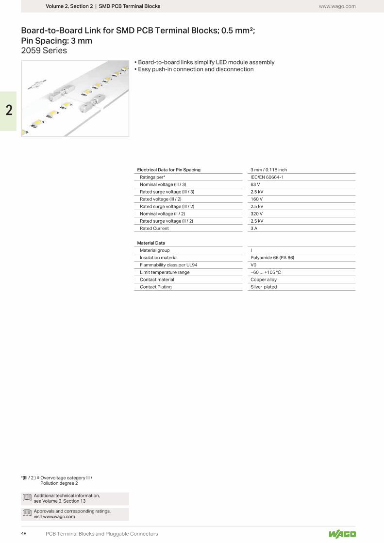
Volume 2, Section 2 | SMD PCB Terminal Blocks www.wago.com
PCB Terminal Blocks and Pluggable Connectors
Board-to-Board Link for SMD PCB Terminal Blocks; 0.5 mm²; Pin Spacing: 3 mm2059 Series
• Board-to-board links simplify LED module assembly• Easy push-in connection and disconnection
Electrical Data for Pin Spacing 3 mm / 0.118 inchRatings per* IEC/EN 60664-1Nominal voltage (III / 3) 63 VRated surge voltage (III / 3) 2.5 kVRated voltage (III / 2) 160 VRated surge voltage (III / 2) 2.5 kVNominal voltage (II / 2) 320 VRated surge voltage (II / 2) 2.5 kVRated Current 3 A
Material DataMaterial group IInsulation material Polyamide 66 (PA 66)Flammability class per UL94 V0Limit temperature range … +105 °CContact material Copper alloyContact Plating Silver-plated
Additional technical information, see Volume 2, Section 13
Approvals and corresponding ratings, visit www.wago.com
Pollution degree 2
48
2
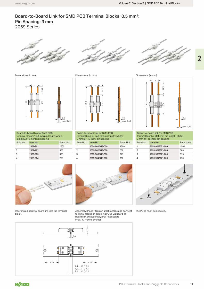
__><
2,5<____________
____________>
><3
__><max. 0,63
3,05
<
9,2<
_____
<
_____
15,3
<_
<_
<_ 0,6
2,75
≤ 20 <<
≤ 20
2,4 … 3,3 (15,3)4,6 … 5,1 (17,5)7,6 … 8,2 (20,5)
<<
<________________________<
<_
__><
2,5
<______________
____________>
><3
__><max. 0,63
4,15<
9,2<
_____
<
_____
17,5
__><
2,5
<__________________
__________________>
><3
__><
max. 0,63
5,65
<_
<_
9,2<
_____
<
_____
20,5
Volume 2, Section 2 | SMD PCB Terminal Blockswww.wago.com
PCB Terminal Blocks and Pluggable Connectors
Board-to-Board Link for SMD PCB Terminal Blocks; 0.5 mm²; Pin Spacing: 3 mm2059 Series
): ): ):
Board-to-board link for SMD PCB terminal blocks; 15.3 mm pin length; white; 3 mm (0.118 inch) pin spacing
Board-to-board link for SMD PCB terminal blocks; 17.5 mm pin length; white; 3 mm (0.118 inch) pin spacing
Board-to-board link for SMD PCB terminal blocks; 20.5 mm pin length; white; 3 mm (0.118 inch) pin spacing
Pole No. Item No. Pack. Unit Pole No. Item No. Pack. Unit Pole No. Item No. Pack. Unit1 2059-901 1500 1 2059-901/018-000 1500 1 2059-901/021-000 1500
2 2059-902 500 2 2059-902/018-000 500 2 2059-902/021-000 500
3 2059-903 375 3 2059-903/018-000 375 3 2059-903/021-000 375
4 2059-904 250 4 2059-904/018-000 250 4 2059-904/021-000 250
terminal blocks on adjoining PCBs via board-to-board link. Disassembly: Pull PCBs apart (max. 10 mating cycles).
Inserting a board-to-board link into the terminal block.
The PCBs must be secured.
49
2
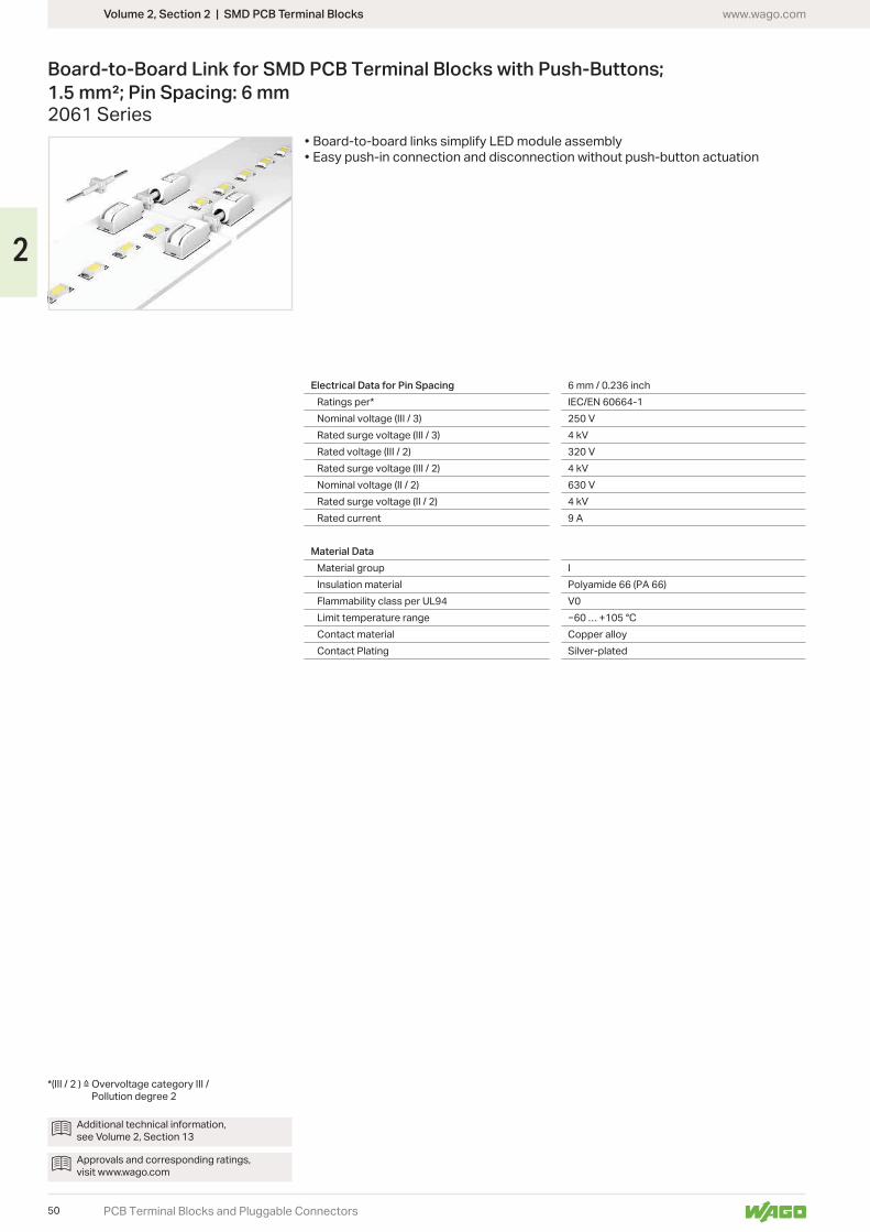
Volume 2, Section 2 | SMD PCB Terminal Blocks www.wago.com
PCB Terminal Blocks and Pluggable Connectors
Board-to-Board Link for SMD PCB Terminal Blocks with Push-Buttons; 1.5 mm²; Pin Spacing: 6 mm2061 Series
• Board-to-board links simplify LED module assembly• Easy push-in connection and disconnection without push-button actuation
Electrical Data for Pin Spacing 6 mm / 0.236 inchRatings per* IEC/EN 60664-1Nominal voltage (III / 3) 250 VRated surge voltage (III / 3) 4 kVRated voltage (III / 2) 320 VRated surge voltage (III / 2) 4 kVNominal voltage (II / 2) 630 VRated surge voltage (II / 2) 4 kVRated current 9 A
Material DataMaterial group IInsulation material Polyamide 66 (PA 66)Flammability class per UL94 V0Limit temperature range … +105 °CContact material Copper alloyContact Plating Silver-plated
Additional technical information, see Volume 2, Section 13
Approvals and corresponding ratings, visit www.wago.com
Pollution degree 2
50
2
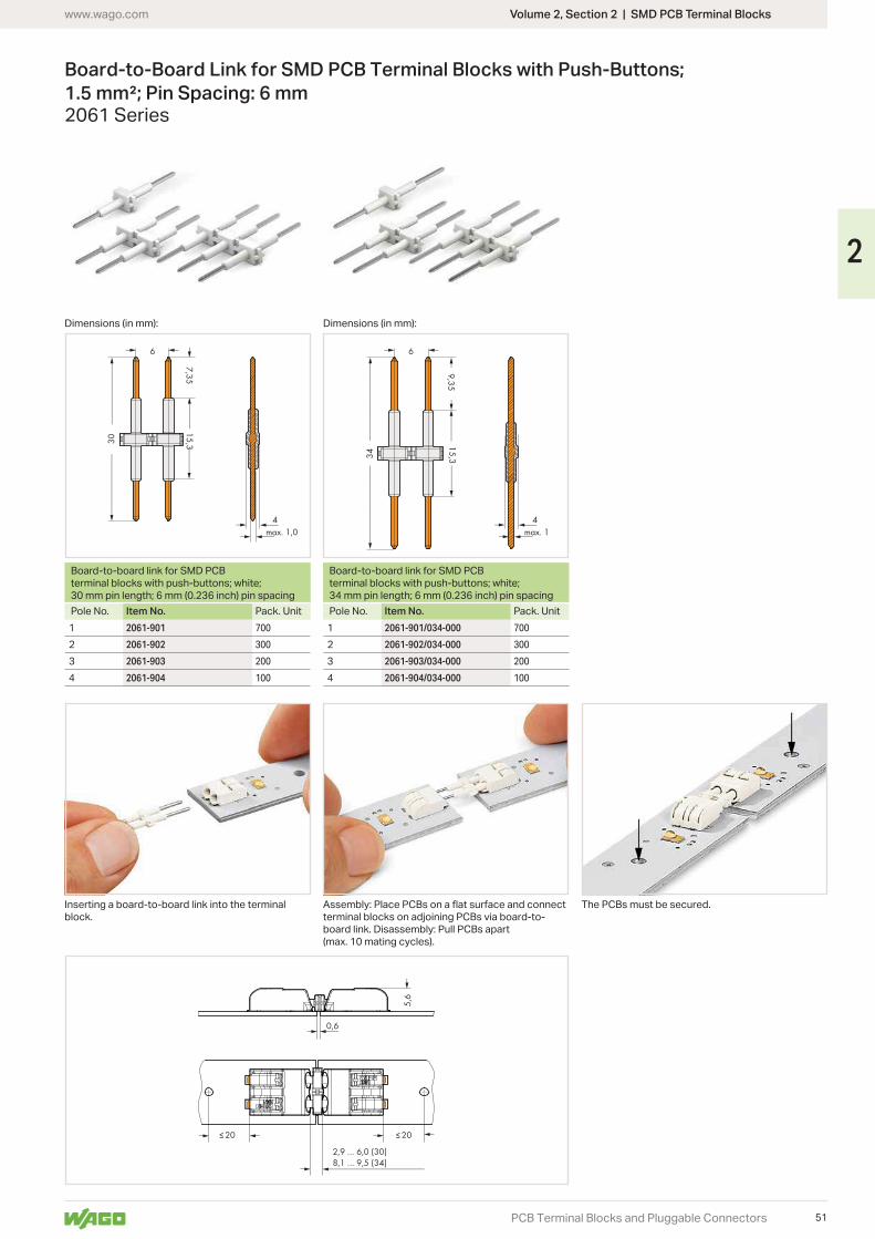
__><
4
<__________________
__________________>
>< 6
__><max. 1
9,35
<
<15,3
<_____
<
_____
34
≤ 20 <<
<
<
≤ 20
0,6
5,6
2,9 … 6,0 (30)8,1 … 9,5 (34)
<<
<______________________
<__
<
__><
4<______________
______________>
>< 6
__><max. 1,0
7,35
<
15,3<
_____
<
_____
30
Volume 2, Section 2 | SMD PCB Terminal Blockswww.wago.com
PCB Terminal Blocks and Pluggable Connectors
Board-to-Board Link for SMD PCB Terminal Blocks with Push-Buttons; 1.5 mm²; Pin Spacing: 6 mm2061 Series
Dimensions (in mm): Dimensions (in mm):
Board-to-board link for SMD PCB terminal blocks with push-buttons; white; 30 mm pin length; 6 mm (0.236 inch) pin spacing
Board-to-board link for SMD PCB terminal blocks with push-buttons; white; 34 mm pin length; 6 mm (0.236 inch) pin spacing
Pole No. Item No. Pack. Unit Pole No. Item No. Pack. Unit1 2061-901 700 1 2061-901/034-000 700
2 2061-902 300 2 2061-902/034-000 300
3 2061-903 200 3 2061-903/034-000 200
4 2061-904 100 4 2061-904/034-000 100
terminal blocks on adjoining PCBs via board-to-board link. Disassembly: Pull PCBs apart (max. 10 mating cycles).
Inserting a board-to-board link into the terminal block.
The PCBs must be secured.
51
2
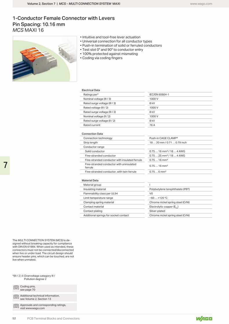
Volume 2, Section 7 | MCS – MULTI CONNECTION SYSTEM MAXI www.wago.com
PCB Terminal Blocks and Connectors
1-Conductor Female Connector with LeversPin Spacing: 10.16 mmMCS MAXI 16
The MULTI CONNECTION SYSTEM (MCS) is de-signed without breaking capacity for compliance
connectors must not be connected/disconnected when live or under load. The circuit design should ensure header pins, which can be touched, are not live when unmated.
Coding pins, see page 70
Additional technical information, see Volume 2, Section 13
Approvals and corresponding ratings, visit www.wago.com
Pollution degree 2
Electrical DataRatings per* IEC/EN 60664-1Nominal voltage (III / 3) 1000 VRated surge voltage (III / 3) 8 kVRated voltage (III / 2) 1000 VRated surge voltage (III / 2) 8 kVNominal voltage (II / 2) 1000 VRated surge voltage (II / 2) 8 kVRated current 76 A
Connection DataConnection technology Push-in CAGE CLAMP®Strip length 18 … 20 mm / 0.71 … 0.79 inchConductor range
Solid conductorFine-stranded conductorFine-stranded conductor with insulated ferruleFine-stranded conductor with uninsulated ferruleFine-stranded conductor, with twin ferrule
Material DataMaterial group IInsulating material Polybutylene terephthalate (PBT)Flammability class per UL94 V0Limit temperature range … +120 °CClamping spring material Chrome nickel spring steel (CrNi)Contact material Electrolytic copper (ECu)Contact plating Silver-platedAdditional springs for socket contact Chrome nickel spring steel (CrNi)
• Intuitive and tool-free lever actuation• Universal connection for all conductor types• Push-in termination of solid or ferruled conductors• Test slot 0° and 90° to conductor entry• 100% protected against mismating• Coding via coding fingers
52
7
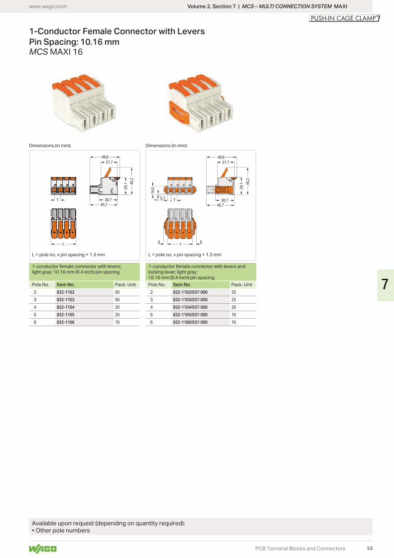
29,1 45
,2
45,730,7
27,749,8
T
L29
,1 45,2
14,5
2 5,7
45,730,7
49,8
L
T
27,7
6 6
Volume 2, Section 7 | MCS – MULTI CONNECTION SYSTEM MAXIwww.wago.com
PCB Terminal Blocks and Connectors
1-Conductor Female Connector with LeversPin Spacing: 10.16 mmMCS MAXI 16
Dimensions (in mm): Dimensions (in mm):
L = pole no. x pin spacing + 1.3 mm L = pole no. x pin spacing + 1.3 mm
1-conductor female connector with levers; light gray; 10.16 mm (0.4 inch) pin spacing
1-conductor female connector with levers and locking lever; light gray; 10.16 mm (0.4 inch) pin spacing
Pole No. Item No. Pack. Unit Pole No. Item No. Pack. Unit832-1102 50 832-1102/037-000 25
832-1103 50 832-1103/037-000 25
832-1104 20 832-1104/037-000 20
832-1105 20 832-1105/037-000 10
832-1106 10 832-1106/037-000 10
Available upon request (depending on quantity required):• Other pole numbers
53
7
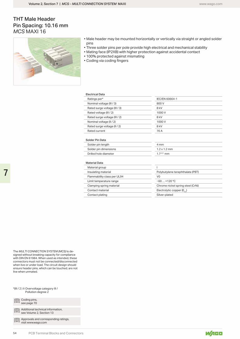
Volume 2, Section 7 | MCS – MULTI CONNECTION SYSTEM MAXI www.wago.com
PCB Terminal Blocks and Connectors
THT Male Header Pin Spacing: 10.16 mmMCS MAXI 16
• Male header may be mounted horizontally or vertically via straight or angled solder pins
• Three solder pins per pole provide high electrical and mechanical stability• Mating face (IP2XB) with higher protection against accidental contact• 100% protected against mismating• Coding via coding fingers
The MULTI CONNECTION SYSTEM (MCS) is de-signed without breaking capacity for compliance
connectors must not be connected/disconnected when live or under load. The circuit design should ensure header pins, which can be touched, are not live when unmated.
Pollution degree 2
Electrical DataRatings per* IEC/EN 60664-1Nominal voltage (III / 3) 800 VRated surge voltage (III / 3) 8 kVRated voltage (III / 2) 1000 VRated surge voltage (III / 2) 8 kVNominal voltage (II / 2) 1000 VRated surge voltage (II / 2) 8 kVRated current 76 A
Solder Pin DataSolder pin length 4 mmSolder pin dimensions 1.2 x 1.2 mmDrilled hole diameter 1.7+0.1 mm
Material DataMaterial group IInsulating material Polybutylene terephthalate (PBT)Flammability class per UL94 V0Limit temperature rangeClamping spring material Chrome nickel spring steel (CrNi)Contact material Electrolytic copper (ECu)Contact plating Silver-plated
Coding pins, see page 70
Additional technical information, see Volume 2, Section 13
Approvals and corresponding ratings, visit www.wago.com
54
7
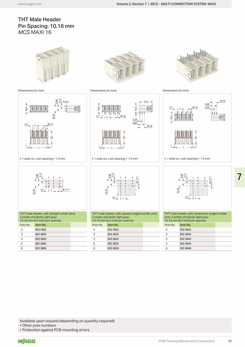
10,1
632
5,08 3,17
16,5
4
5,7
11
Ø 1,2
1 2 3 4
L
T
10,1
65,
08 3,17
Ø 1,7+0,15,7
1 2 n
T
32
16,5
16,5
4
31,8
2,245,08
5,7
11
Ø 1,21 2 3 4
10,16
T
L
10,1
65,
08 3,17
Ø 1
,7+0
,1
5,7
1 2
T
n
32
16,5
2,245,7
11
Ø 1,2
1 2 3 4
5,0810,16
T
L
10,1
65,
08 3,17
Ø 1
,7+0
,1
5,7
n21
T
Volume 2, Section 7 | MCS – MULTI CONNECTION SYSTEM MAXIwww.wago.com
PCB Terminal Blocks and Connectors
THT Male Header Pin Spacing: 10.16 mmMCS MAXI 16
Dimensions (in mm): Dimensions (in mm): Dimensions (in mm):
L = pole no. x pin spacing + 1.3 mm L = pole no. x pin spacing + 1.3 mm L = pole no. x pin spacing + 1.3 mm
THT male header; with straight solder pins; 3 solder pins/pole; light gray; 10.16 mm (0.4 inch) pin spacing
THT male header; with upward-angled solder pins; 3 solder pins/pole; light gray; 10.16 mm (0.4 inch) pin spacing
THT male header; with downward-angled solder pins; 3 solder pins/pole; light gray; 10.16 mm (0.4 inch) pin spacing
Pole No. Item No. Pole No. Item No. Pole No. Item No.832-3602 832-3622 832-3642
832-3603 832-3623 832-3643
832-3604 832-3624 832-3644
832-3605 832-3625 832-3645
832-3606 832-3626 832-3646
Available upon request (depending on quantity required):• Other pole numbers• Protection against PCB mounting errors
55
7
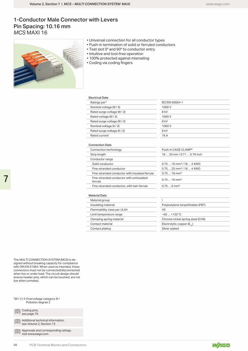
Volume 2, Section 7 | MCS – MULTI CONNECTION SYSTEM MAXI www.wago.com
PCB Terminal Blocks and Connectors
1-Conductor Male Connector with LeversPin Spacing: 10.16 mmMCS MAXI 16
• Universal connection for all conductor types• Push-in termination of solid or ferruled conductors• Test slot 0° and 90° to conductor entry• Intuitive and tool-free operation• 100% protected against mismating• Coding via coding fingers
The MULTI CONNECTION SYSTEM (MCS) is de-signed without breaking capacity for compliance
connectors must not be connected/disconnected when live or under load. The circuit design should ensure header pins, which can be touched, are not live when unmated.
Pollution degree 2
Electrical DataRatings per* IEC/EN 60664-1Nominal voltage (III / 3) 1000 VRated surge voltage (III / 3) 8 kVRated voltage (III / 2) 1000 VRated surge voltage (III / 2) 8 kVNominal voltage (II / 2) 1000 VRated surge voltage (II / 2) 8 kVRated current 76 A
Connection DataConnection technology Push-in CAGE CLAMP®Strip length 18 … 20 mm / 0.71 … 0.79 inchConductor range
Solid conductorFine-stranded conductorFine-stranded conductor with insulated ferruleFine-stranded conductor with uninsulated ferruleFine-stranded conductor, with twin ferrule
Material DataMaterial group IInsulating material Polybutylene terephthalate (PBT)Flammability class per UL94 V0Limit temperature range … +120 °CClamping spring material Chrome nickel spring steel (CrNi)Contact material Electrolytic copper (ECu)Contact plating Silver-plated
Coding pins, see page 70
Additional technical information, see Volume 2, Section 13
Approvals and corresponding ratings, visit www.wago.com
56
7
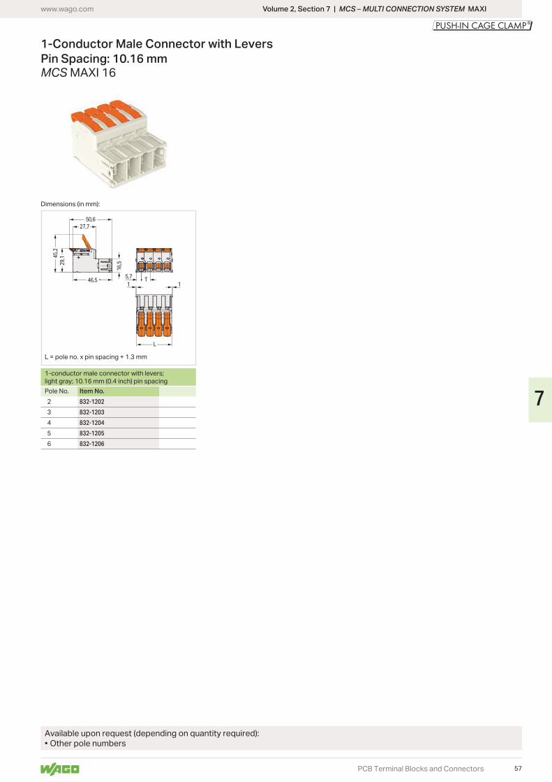
29,145
,2
16,5
T1 1
5,746,5
50,627,7
L
Volume 2, Section 7 | MCS – MULTI CONNECTION SYSTEM MAXIwww.wago.com
PCB Terminal Blocks and Connectors
1-Conductor Male Connector with LeversPin Spacing: 10.16 mmMCS MAXI 16
Dimensions (in mm):
L = pole no. x pin spacing + 1.3 mm
1-conductor male connector with levers; light gray; 10.16 mm (0.4 inch) pin spacingPole No. Item No.
832-1202
832-1203
832-1204
832-1205
832-1206
Available upon request (depending on quantity required):• Other pole numbers
57
7
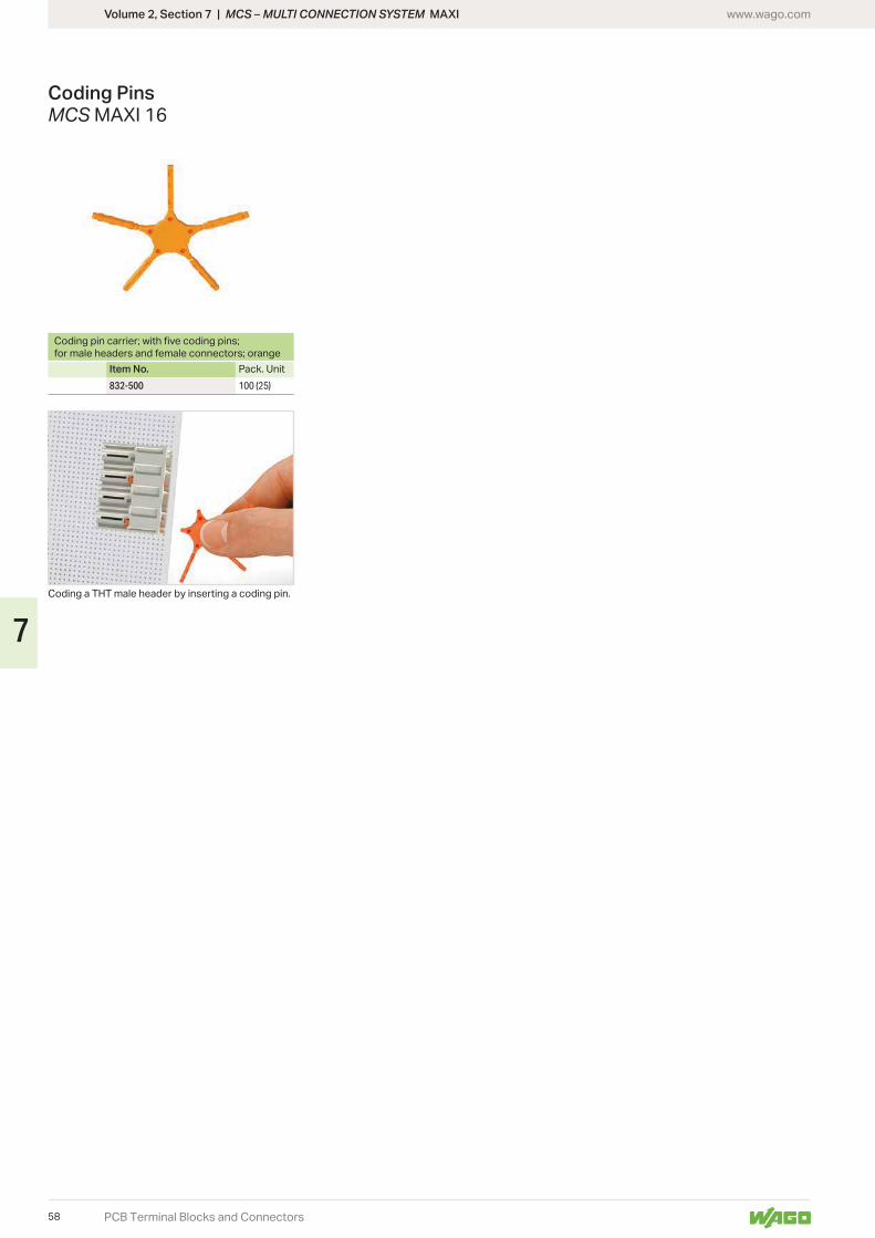
Volume 2, Section 7 | MCS – MULTI CONNECTION SYSTEM MAXI www.wago.com
PCB Terminal Blocks and Connectors
Coding PinsMCS MAXI 16
Coding a THT male header by inserting a coding pin.
for male headers and female connectors; orange
Item No. Pack. Unit832-500 100 (25)
58
7

23,3
11,1
Ø 5,8
Ø 3
28,1
3,5
L
8
1724
8,31,87,5
L
8,7
2,7
8,3
18,6
<_______
<_
<_
<___
<
<___
<
<__
<
<_______
Volume 2, Section 7 | MCS – MULTI CONNECTION SYSTEM MAXIwww.wago.com
PCB Terminal Blocks and Connectors
Snap-In Frames and Lockout PinsMCS MAXI 6
Snap-in frame for MCS MAXI male connectors; light gray
Lockout pins for snap-in frames; light gray
Pole No. Item No. Pack. Unit Item No. Pack. Unit2 45.84 mm 831-302 48 831-321 100
3 831-303 48
4 831-304 24
5 831-305 12
Insert the snap-in frame into the cutout.
Inserting a female connector equipped with lateral locking levers.
Insert the male connector into the snap-in frame.
Inserting a female connector without lateral locking levers – lockout pins are inserted on both sides of the snap-in frame.
Dimensions (in mm): Dimensions (in mm): Dimensions (in mm):
• Snap-in frames for through-panel MCS MAXI 6 connectors• Fast and easy installation – without tools• Compatible with MCS MAXI 6 male and female connectors• For panel thickness ranging from 0.5 to 2.5 mm• Optional screw mounting
L = (pole no. x 7.62 mm) + 30.6 mm L = (pole no. x 7.62 mm) + 26.8 mm
Panel cutout for snap-in frame
59
7
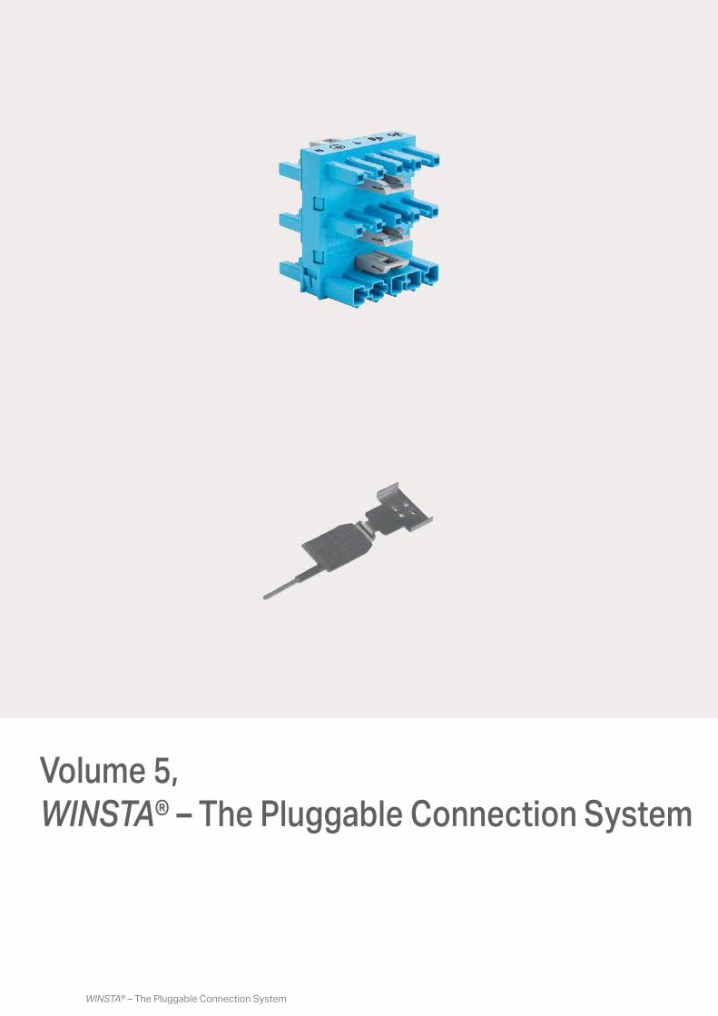
WINSTA® – The Pluggable Connection System
Volume 5, WINSTA® – The Pluggable Connection System
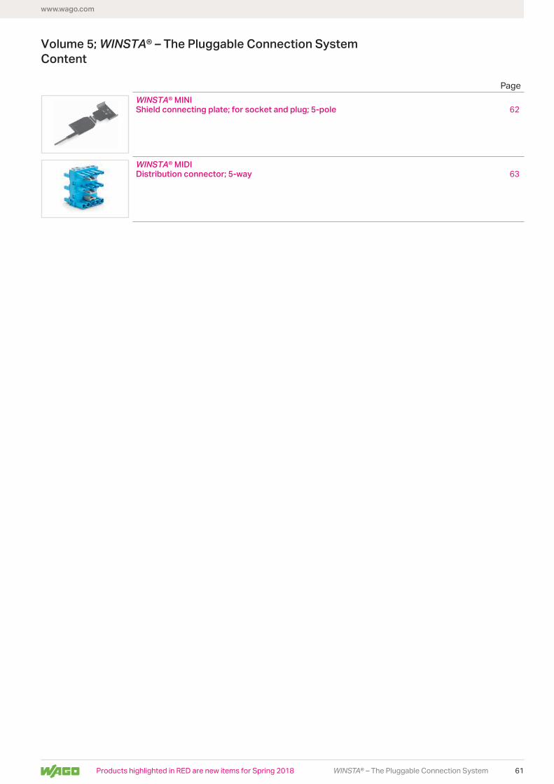
www.wago.com
61WINSTA® – The Pluggable Connection System
Volume 5; WINSTA® – The Pluggable Connection SystemContent
WINSTA® MINIShield connecting plate; for socket and plug; 5-pole 62
WINSTA® MIDIDistribution connector; 5-way 63
Page
Products highlighted in RED are new items for Spring 2018
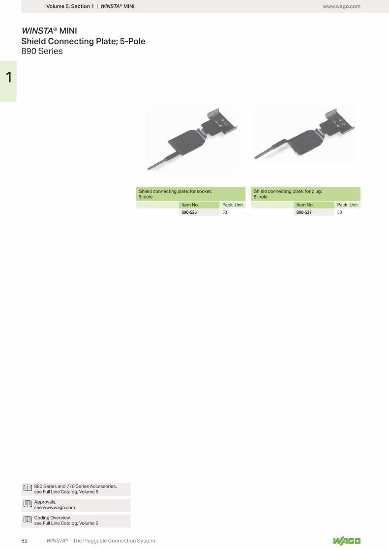
www.wago.com
62
1
WINSTA® – The Pluggable Connection System
Volume 5, Section 1 | WINSTA® MINI
WINSTA® MINI Shield Connecting Plate; 5-Pole890 Series
Shield connecting plate; for socket; 5-pole
Item No. Pack. Unit890-526 50
Shield connecting plate; for plug; 5-pole
Item No. Pack. Unit890-527 50
890 Series and 770 Series Accessories, see Full Line Catalog, Volume 5
Approvals, see www.wago.com
Coding Overview, see Full Line Catalog, Volume 5
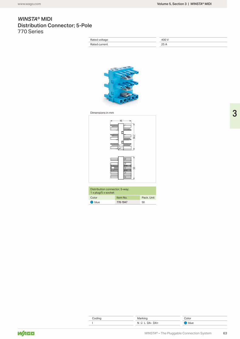
www.wago.com
63
46
5058
,2
3
WINSTA® – The Pluggable Connection System
Volume 5, Section 3 | WINSTA® MIDI
Dimensions in mm
Rated voltage 400 VRated current 25 A
WINSTA® MIDI Distribution Connector; 5-Pole770 Series
Coding Marking ColorI N 3 L DA- DA+ blue
Distribution connector; 5-way; 1 x plug/5 x socketColor Item No. Pack. Unit
blue 770-1947 50
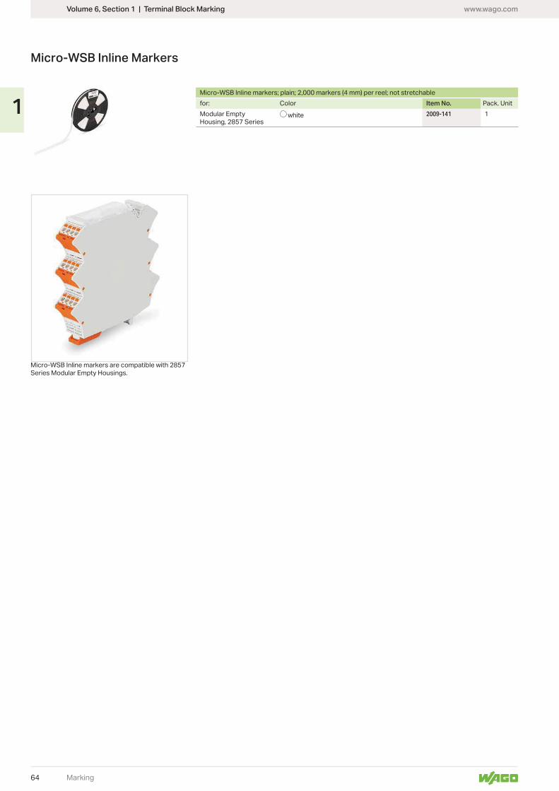
www.wago.com
64
1
Marking
Micro-WSB Inline Markers
Series Modular Empty Housings.
for: Color Item No. Pack. UnitModular Empty Housing, 2857 Series
white 2009-141 1
Volume 6, Section 1 | Terminal Block Marking
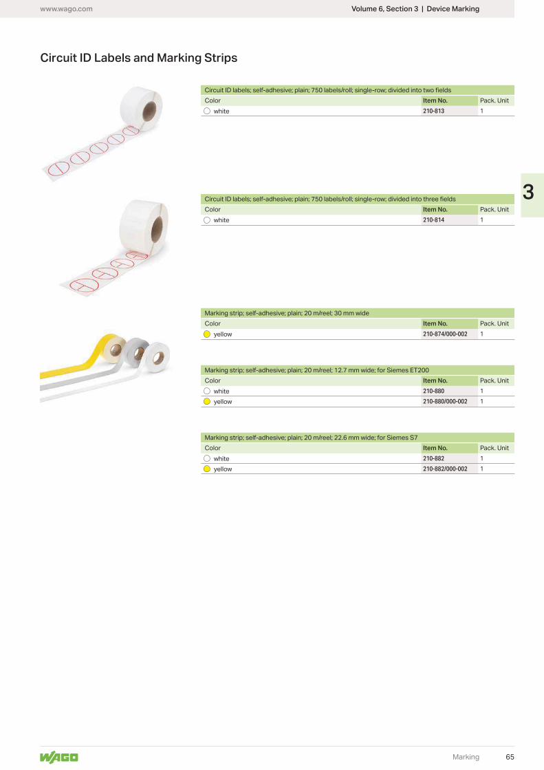
www.wago.com
65
3
Marking
Color Item No. Pack. Unitwhite 210-813 1
Circuit ID Labels and Marking Strips
Volume 6, Section 3 | Device Marking
Color Item No. Pack. Unitwhite 210-814 1
Marking strip; self-adhesive; plain; 20 m/reel; 30 mm wideColor Item No. Pack. Unit
yellow 210-874/000-002 1
Marking strip; self-adhesive; plain; 20 m/reel; 12.7 mm wide; for Siemes ET200Color Item No. Pack. Unit
white 210-880 1
yellow 210-880/000-002 1
Marking strip; self-adhesive; plain; 20 m/reel; 22.6 mm wide; for Siemes S7Color Item No. Pack. Unit
white 210-882 1
yellow 210-882/000-002 1
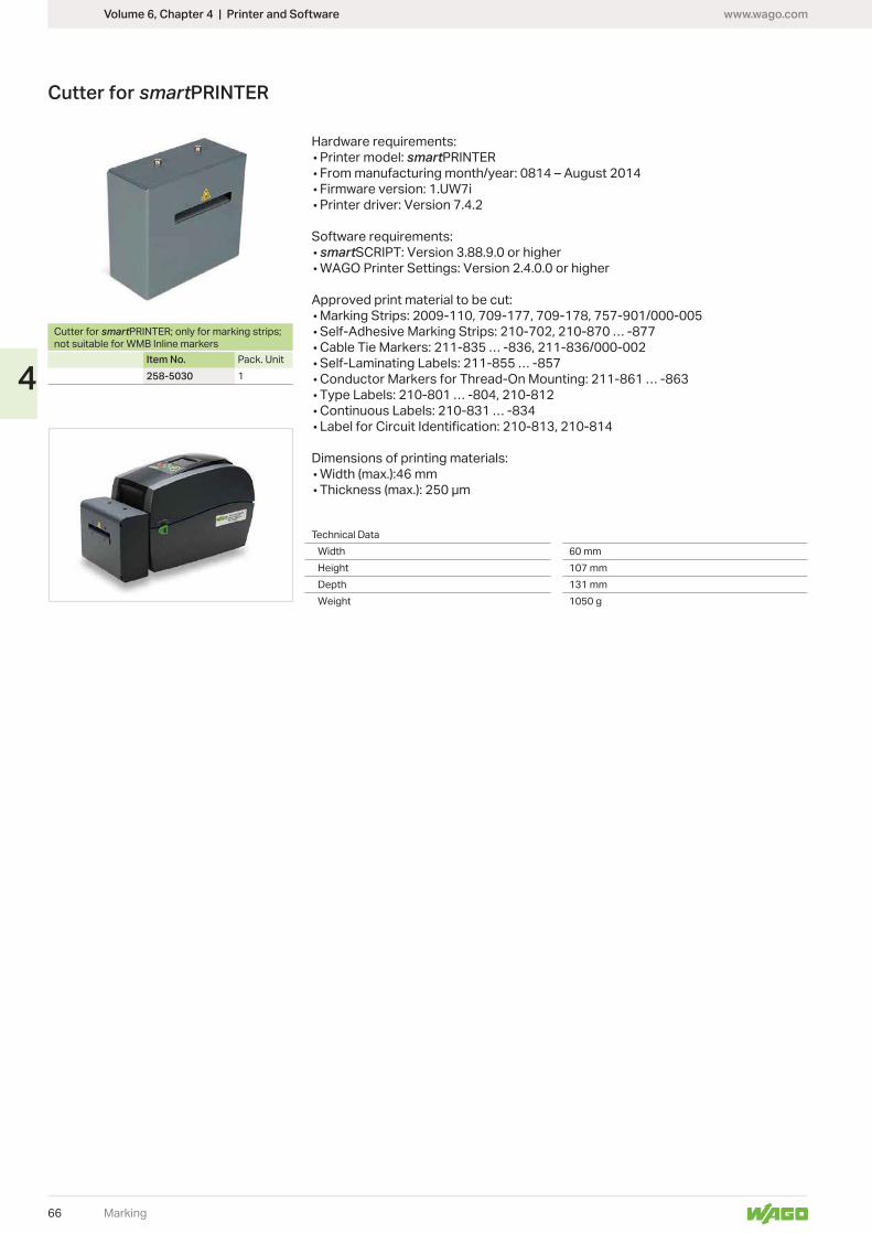
www.wago.com
66
4
Marking
Hardware requirements:• Printer model: smartPRINTER• From manufacturing month/year: 0814 – August 2014• • Printer driver: Version 7.4.2
Software requirements:• smartSCRIPT: Version 3.88.9.0 or higher•
Approved print material to be cut:• Marking Strips: 2009-110, 709-177, 709-178, 757-901/000-005• Self-Adhesive Marking Strips: 210-702, 210-870 … -877• Cable Tie Markers: 211-835 … -836, 211-836/000-002• Self-Laminating Labels: 211-855 … -857• Conductor Markers for Thread-On Mounting: 211-861 … -863• Type Labels: 210-801 … -804, 210-812• Continuous Labels: 210-831 … -834•
Dimensions of printing materials:• • Thickness (max.): 250 μm
Technical Data60 mm
Height 107 mmDepth 131 mm
1050 g
Cutter for smartPRINTER; only for marking strips;
Item No. Pack. Unit258-5030 1
Cutter for smartPRINTER
Volume 6, Chapter 4 | Printer and Software
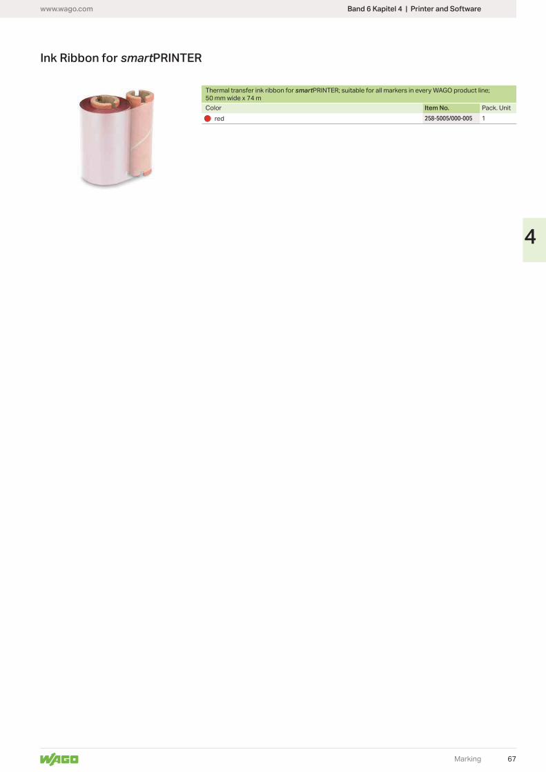
www.wago.com
67
4
Marking
Thermal transfer ink ribbon for smart50 mm wide x 74 mColor Item No. Pack. Unit
red 258-5005/000-005 1
Ink Ribbon for smartPRINTER
Band 6 Kapitel 4 | Printer and Software

68
www.wago.com
Item No. Item No. Item No. Item No.Page Page Page Page
Item Number Index
Item Number Index
Products highlighted in RED are new items for Spring 2018
210 Series210-334 13
210-702 66210-719 9
210-801 66210-812 66210-813 65210-813 65210-813 66210-814 65210-814 65210-814 66210-814 66210-831 66210-870 66210-874/000-002 65210-874/000-002 65210-880 65210-880 65210-880/000-002 65210-880/000-002 65210-882 65210-882 65210-882/000-002 65210-882/000-002 65
211 Series211-835 66211-836/000-002 66211-855 66211-861 66
221 Series221-510 13
221-612 13221-613 13221-615 13
258 Series258-5005/000-005 67258-5030 66
280 Series280-470 8280-471 8280-472 8
282 Series282-435/300-000 4
709 Series709-107 9709-177 66709-178 66
726 Series726-780 9
726-800 9726-801 9
726-905 9
757 Series757-901/000-005 66
769 Series769-101 8769-101/022-000 8
769-435 8769-438 8769-439 8
770 Series770-1947 63
793 Series793-5501 5793-5501/000-002 5793-5501/000-005 5793-5501/000-006 5793-5501/000-007 5793-5501/000-012 5793-5501/000-017 5793-5501/000-023 5793-5501/000-024 5
831 Series831-302 59831-303 59831-304 59831-305 59831-321 59
832 Series832-500 58
832-1102 53832-1102/037-000 53832-1103 53832-1103/037-000 53832-1104 53832-1104/037-000 53832-1105 53832-1105/037-000 53832-1106 53832-1106/037-000 53
832-1202 57832-1203 57832-1204 57832-1205 57832-1206 57
832-3602 55832-3603 55832-3604 55832-3605 55832-3606 55832-3622 55832-3623 55832-3624 55832-3625 55832-3626 55832-3642 55832-3643 55832-3644 55832-3645 55832-3646 55
870 Series870-402 8870-403 8870-404 8870-405 8870-405/011-000 8870-406 8870-406/020-000 8870-407 8870-407/011-000 8870-408 8870-409 8870-409/011-000 8870-410 8870-433 8870-434 8870-435 8870-436 8870-437 8870-438 8870-439 8870-440 8
870-1131 8870-1137 8870-1138 8870-1148 8870-1149 8
887 Series887-917 10887-918 10887-950 11887-952 10887-953 11887-955 11
890 Series890-526 62890-527 62
2002 Series2002-115 5
2002-402 52002-403 52002-404 52002-405 52002-406 52002-407 52002-408 52002-409 52002-410 52002-433 52002-434 52002-435 52002-436 52002-437 52002-438 52002-439 52002-440 52002-472 52002-473 52002-474 52002-475 52002-476 52002-477 52002-478 52002-479 52002-480 52002-481 52002-482 5
2002-1661 52002-1691 52002-1692 5
2002-1761 52002-1791 52002-1792 5
2002-1861 52002-1891 52002-1892 5
2002-1961 52002-1991 52002-1992 5
2003 Series2003-499 6
2003-500 6
2003-911 62003-911/1000-923 6
2003-6661 62003-6692 62003-6693 62003-6694 6
2004 Series2004-911 6
2009 Series2009-110 92009-115 92009-141 64
2009-412 5
2009 Series2009-414 52009-414/000-005 42009-414/000-006 42009-416 5
2042 Series2042-321 52042-331 52042-341 52042-351 5
2059 Series2059-901 492059-901/018-000 492059-901/021-000 492059-902 492059-902/018-000 492059-902/021-000 492059-903 492059-903/018-000 492059-903/021-000 492059-904 492059-904/018-000 492059-904/021-000 49
2061 Series2061-901 512061-901/034-000 512061-902 512061-902/034-000 512061-903 512061-903/034-000 512061-904 512061-904/034-000 51
2065 Series2065-100/998-403 472065-101/998-403 472065-189 47
2070 Series2070-400 452070-451/998-406 412070-452/998-406 412070-453/998-406 412070-461/998-406 422070-462/998-406 422070-463/998-406 42
2070-521/998-406 432070-522/998-406 432070-523/998-406 432070-541/998-406 442070-542/998-406 442070-543/998-406 44
2604 Series2604-1101 172604-1102 172604-1103 172604-1104 172604-1105 172604-1106 172604-1107 172604-1108 172604-1109 172604-1110 172604-1111 172604-1112 17
2604-1302 172604-1303 172604-1304 172604-1305 172604-1306 172604-1307 172604-1308 172604-1309 172604-1310 172604-1311 17
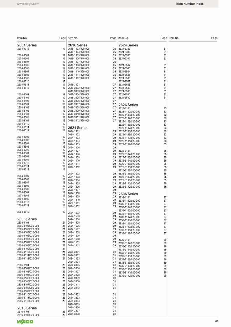
69
www.wago.com
Item No. Item No. Item No. Item No.Page Page Page Page
Item Number Index
2604 Series2604-1312 17
2604-1502 172604-1503 172604-1504 172604-1505 172604-1506 172604-1507 172604-1508 172604-1509 172604-1510 172604-1511 172604-1512 17
2604-3101 192604-3102 192604-3103 192604-3104 192604-3105 192604-3106 192604-3107 192604-3108 192604-3109 192604-3110 192604-3111 192604-3112 19
2604-3302 192604-3303 192604-3304 192604-3305 192604-3306 192604-3307 192604-3308 192604-3309 192604-3310 192604-3311 192604-3312 19
2604-3502 192604-3503 192604-3504 192604-3505 192604-3506 192604-3507 192604-3508 192604-3509 192604-3510 192604-3511 19
2604-3512 19
2606 Series2606-1101 212606-1102/020-000 212606-1103/020-000 212606-1104/020-000 212606-1105/020-000 212606-1106/020-000 212606-1107/020-000 212606-1108/020-000 212606-1109/020-000 212606-1110/020-000 212606-1111/020-000 212606-1112/020-000 21
2606-3101 232606-3102/020-000 232606-3103/020-000 232606-3104/020-000 232606-3105/020-000 232606-3106/020-000 232606-3107/020-000 232606-3108/000-000 232606-3109/020-000 232606-3110/020-000 232606-3111/020-000 232606-3112/020-000 23
2616 Series2616-1101 252616-1102/020-000 25
2616 Series2616-1103/020-000 252616-1104/020-000 252616-1105/020-000 252616-1106/020-000 252616-1107/020-000 252616-1108/020-000 252616-1109/020-000 252616-1110/020-000 252616-1111/020-000 252616-1112/020-000 25
2616-3101 272616-3102/020-000 272616-3103/020-000 272616-3104/020-000 272616-3105/020-000 272616-3106/020-000 272616-3107/020-000 272616-3108/020-000 272616-3109/020-000 272616-3110/020-000 272616-3111/020-000 272616-3112/020-000 27
2624 Series2624-1101 292624-1102 292624-1103 292624-1104 292624-1105 292624-1106 292624-1107 292624-1108 292624-1109 292624-1110 292624-1111 292624-1112 29
2624-1302 292624-1303 292624-1304 292624-1305 292624-1306 292624-1307 292624-1308 292624-1309 292624-1310 292624-1311 292624-1312 29
2624-1502 292624-1503 292624-1504 292624-1505 292624-1506 292624-1507 292624-1508 292624-1509 292624-1510 292624-1511 292624-1512 29
2624-3101 312624-3102 312624-3103 312624-3104 312624-3105 312624-3106 312624-3107 312624-3108 312624-3109 312624-3110 312624-3111 312624-3112 31
2624-3302 312624-3303 312624-3304 312624-3305 312624-3306 312624-3307 312624-3308 31
2624 Series2624-3309 312624-3310 312624-3311 312624-3312 31
2624-3502 312624-3503 312624-3504 312624-3505 312624-3506 312624-3507 312624-3508 312624-3509 312624-3510 312624-3511 312624-3512 31
2626 Series2626-1101 332626-1102/020-000 332626-1103/020-000 332626-1104/020-000 332626-1105/020-000 332626-1106/020-000 332626-1107/020-000 332626-1108/020-000 332626-1109/020-000 332626-1110/020-000 332626-1111/020-000 332626-1112/020-000 33
2626-3101 352626-3102/020-000 352626-3103/020-000 352626-3104/020-000 352626-3105/020-000 352626-3106/020-000 352626-3107/020-000 352626-3108/020-000 352626-3109/020-000 352626-3110/020-000 352626-3111/020-000 352626-3112/020-000 35
2636 Series2636-1101 372636-1102/020-000 372636-1103/020-000 372636-1104/020-000 372636-1105/020-000 372636-1106/020-000 372636-1107/020-000 372636-1108/020-000 372636-1109/020-000 372636-1110/020-000 372636-1111/020-000 372636-1112/020-000 37
2636-3101 392636-3102/020-000 392636-3103/020-000 392636-3104/020-000 392636-3105/020-000 392636-3106/020-000 392636-3107/020-000 392636-3108/020-000 392636-3109/020-000 392636-3110/020-000 392636-3111/020-000 392636-3112/020-000 39
70
www.wago.com
Algeriaplease contact WAGO France
ArgentinaBruno Schillig S.A.Arenales 4030, B1604CFDFlorida, PBAPhone +54 11 4730 1100Fax +54 11 4761 [email protected]
AustraliaWAGO Pty. Ltd.2-4 Overseas DriveNoble Park Victoria 3174Phone +61 03 8791 6300Fax +61 03 9701 [email protected]
NHP ELECTRICAL ENGINEERING PRODUCTS PTY LTD43-67 River StreetRichmond, Victoria, 3121P.O. Box 199Phone +61 3 9429 2999Fax +61 3 9429 [email protected]
AustriaWAGO Kontakttechnik Ges.m.b.H.Europaring F15 602Campus 212345 Brunn am GebirgePhone +43 1 6150780Fax +43 1 [email protected]
AzerbaijanAZ Technics LTD
Y.Safarov str.33, AZ1025,BakuPhone +994 50 210 24 49Fax +994 12 496 83 [email protected]
Bangladeshplease contact WAGO India
BelarusOOO FEKpr-t Pushkina 29-B220015 MinskPhone +375 17 2102189Fax +375 17 [email protected]
UP ATAVA
220006 MinskPhone +375 17 2054015Fax +375 17 2851759
BelgiumWAGO BeLux nvExcelsiorlaan 111930 ZaventemPhone +32 2 717 9090Fax +32 2 717 [email protected]
BoliviaISOTEK S.R.L.Zona Casco ViejoCalle Isso #578, B/San Roque Santa CruzPhone +591 721 000 [email protected]
Bosnia & Herzegovinaplease contact WAGO Bulgaria
ELEKTRON d.o.o. GRUDEHrvatskih branitelja 4688340 GRUDEPhone 00387 39/674 404Fax 00387 39/674 [email protected]
BrazilWAGO Eletroeletrônicos LtdaRua Trípoli, 640, Lotamento Multivias IIJardim Ermida IJundiaí - SP CEP 13212-217Phone +55 (11) 2923 [email protected]
BulgariaWAGO Kontakttechnik GmbH & Co. KG
Business Center Serdika2E Akad. Ivan Geshov Blvd.
Phone +359 2 489 46 09/10Fax +359 2 928 28 [email protected]
Canadaplease contact WAGO USA
ChileDesimat ChileAv Puerto Vespucio 9670Pudahuel SantiagoPhone +56 2 747 0152Fax +56 2 747 [email protected]
ChinaWAGO Electronic (Tianjin) Co., Ltd.No.5, Quan Hui RoadWuqing Development AreaTianjin 301700Phone +86 22 5967 7688Fax +86 22 5961 [email protected]
ColombiaT.H.L. Ltda.Cra. 49 B # 91-33BogotáPhone +57 1 621 85 50Fax +57 1 621 60 [email protected]
CroatiaM.B.A. d.o.o.Frana Supila 551211 MatuljiPhone +385 51 275-736Fax +385 51 [email protected]
MICROSTAR d.o.o.Siget 18 b10020 ZagrebPhone +385 1 3647 849Fax +385 1 3636 [email protected]
Czech RepublicWAGO Elektro spol. sr. o.Rozvodova 1116/36
Phone +420 261 090 143Fax +420 261 090 [email protected]@wago.com
DenmarkWAGO Denmark A/SLejrvej 173500 VærløsePhone +45 44 357 [email protected]
EcuadorECUAINSETEC CIA LTDAYugoslavia N34-110 y AzuayQuitoPhone +593 2 24 50 475Fax +593 2 22 51 [email protected]
EgyptKENANA Automation / System Integrator (Water & Waste Water)2 Building 10, Block 31Ibrahim Shehata StreetNasr CityCairo, EgyptPhone +2 01 02899 3434Fax +2 02 357 [email protected]
IBN Engineering / Distributor (Automation Products)Phone +2 02 3721 4350Fax +2 02 3722 [email protected]
Barkouky Electric / System Integrator (Building Management)Phone +2 02 2269 1192Fax +2 02 2269 [email protected]
EstoniaEltarko OÜLaki 14 - 50210621 TallinnPhone +372 651 7731Fax +372 651 [email protected]
FinlandWAGO Finland OyPerintötie 2 C01510 VantaaPhone +358 9 7744 060Fax +358 9 7744 0660
FranceWAGO Contact SASParis Nord 283 Rue des ChardonneretsB.P. 55065 - Tremblay en France95947 - ROISSY CDG CEDEXPhone +33 1 4817 2590Fax +33 1 4863 [email protected]
GermanyWAGO Kontakttechnik GmbH & Co. KGPostfach 28 80, 32385 MindenHansastraße 2732423 MindenPhone +49 571 887-0Fax +49 571 [email protected]
WAGO Kontakttechnik GmbH & Co. KGWaldstraße 199706 SondershausenPhone +49 3632 659-0Fax +49 3632 [email protected]
Great BritainWAGO LimitedTriton Park, Swift Valley Industrial EstateRUGBYWarwickshire, CV21 1SGPhone +44 1788 568 008Fax +44 1788 568 [email protected]
GreecePANAGIOTIS SP. DIMOULASDIMOULAS AUTOMATIONSKritis Str. 2610439 AthensPhone +30 210 883 3337Fax +30 210 883 [email protected]
HondurasCILASAS S.A. de C.V.Barrio Los Andes7 Calle entre 14 y 15 Ave. N.O.P.O. Box. 1061San Pedro SulaPhone +504 2557 1146/7Fax +504 2557 [email protected]
Hong KongNational Concord Eng., Ltd.Unit A-B, 5/F.Southeast Industrial Building611-619 Castle Peak RoadTsuen Wan, N.T.Phone +852 2429 2611Fax +852 2429 [email protected]
HungaryWAGO Hungá¡ria KFTIpari Park, Gyár u. 22040 BudapestPhone +36 23 502-170Fax +36 23 [email protected]
IcelandS. Gudjonsson ehf.Audbrekku 9-11202 KopavogurPhone +354 520-4500Fax +354 [email protected]
IndiaWAGO Private LimitedC-27, Sector-58, Phase-IIINoida-201 301Gautam Budh Nagar (U.P)Phone +91 120 438 8700Fax +91 120 438 [email protected]
Indonesiaplease contact WAGO Singapore
Irakplease contact WAGO Middle East
IrelandDrives & ControlsUnit F4, Riverview Business ParkNangor RoadDublin 12Phone +353 1 4604474Fax +353 1 [email protected]
IsraelComtel Israel Electronic Solutions Ltd.Bet Hapaamon20 Hataas StreetP.O. Box 6644425 Kefar-SabaPhone +972 9 76 77 240Fax +972 9 76 77 [email protected]
ItalyWAGO Elettronica SRL a Socio UnicoVia Parini 140033 Casalecchio di Reno (BO)Phone +39 051 6132112Fax +39 051 [email protected]
JapanWAGO Co. of JAPAN Ltd.Kinshicho Prime Tower1-5-7, Kameido, Koto-kuTokyo 136-0071Phone +81 3 5627 2050Fax +81 3 5627 [email protected]
JordanOxgen for Engineering Systems Co. L.L.CP.O Box: 2154 Amman11953 JordanPhone +962 79 9 860 869Fax. +962 655 211 [email protected]
KazakhstanTOO INTANT232/2, Ryskulov avenue050061 AlmatyPhone +7 727 356 52 91/92/93Fax +7 727 327 14 92/[email protected][email protected]
TOO Technik-Tradeul. i. A. Protosanova, 81070004 Ust-KamenogorskPhone +7 7232 254 064Fax +7 7232 253 [email protected]
Nova Solut LLC (System Integrator)050042, The Republic Of Kazakhstan,Almaty city, Toktabayeva 23, #10Phone +7 777 206 04 [email protected]@novasolut.kz
KoreaWAGO Korea Co., Ltd.Room 205 AnyangMegaValley,268, Hagui-ro, Dongan-gu, Anyang-si, Gyeonggi-do, 14056, South KoreaPhone +82 31 421 [email protected]
Kosovoplease contact WAGO Bulgaria
LatviaINSTABALT LATVIA SIAVestienas iela 6
Phone +371 6790 1188Fax +371 6790 [email protected]
LebanonGemayel Trading & ContractingRue 55, Antonins Project-Bloc LP.O. BOX 70-1096Antelias, LebanonPhone +961 3 223 029Fax +961 4 521 [email protected]
LithuaniaINSTABALT LIT UAB
Vilnius, 2053Phone +370 52 322 295Fax +370 52 322 [email protected]
Luxembourgplease contact WAGO Belgium
Macedoniaplease contact WAGO Bulgaria
Kompjunet InzeneringVladimir Komarov 1A-3/91000 SkopjePhone +389 2 521 12 00
WAGO WorldwideCompanies and Representatives
Addresses
71
www.wago.com
Malaysia
No 806, Block A4, Leisure Commerce Square,No 9, Jalan PJS 8/9, 46150 Petaling Jaya,Selangor Darul Ehsan, MalaysiaPhone +60 3 7877 1776Fax +60 3 7877 [email protected]
HPH Materials (M) Sdn BhdNo. 4, Jalan Nilam 1/6Suban Hi-Tech Industrial Park40000 Shah AlamSelangor, D.E. MalaysiaPhone +60 3 5638 2213Fax +60 3 5638 [email protected]
Maledivesplease contact WAGO India
MexicoWAGO SA de CVCarretera estatal 431 Km. 2+200Lote 99 Módulo 6Parque Industrial Tecnológico InnovsciónQuerétaroEl Marqués, Qro. 76246Phone +52 442 221 5946Fax +52 442 221 [email protected]
MoldovaElectroservice Slavinschi T.T.
2001 KishinevPhone +373 22 274427Fax +373 22 [email protected]
MoroccoAutomatisme & Connection Maroc23, Rue Boured2ème étage, appt4Roche Noire20300 CasablancaPhone +212 522 24 21 72/73Fax +212 522 24 21 [email protected]
Nepalplease contact WAGO India
NetherlandsWAGO Nederland B.V.Laan van de Ram 197234 BW APELDOORNPhone +31 55 36 83 500Fax +31 55 36 83 [email protected]
New Zealandplease contact WAGO Australia
NHP NZ7 Lockhart PlaceMt WellingtonPhone +64 9 2761967Fax +64 9 [email protected]
NigeriaGIL Automations Ltd.Daily Times Complex2 Lateef Jakande Rd., Agidingbi100271 Ikeja, Lagos StatePhone +234 [email protected]
NorwayWAGO Norge ASJerikoveien 201067 OsloPhone +47 22 30 94 50Fax +47 22 30 94 [email protected]
Omanplease contact WAGO Middle East
PakistanFuziLogiX Automation & ControlSuit No. 14, 5th Floor, Shan ArcadeNew Garden Town, LahorePhone +92 42 594 1503 - 4Fax +92 42 585 [email protected]
S.A. Hamid & Co.7 Brandreth RoadLahore, 54000Phone +92 42 376 500 99Fax +92 42 376 513 [email protected]
ParaguayAESAAv. Madame Lynchc/Antolin Irala2309 AsunciónPhone +59 [email protected]
PeruManufacturas Eléctricas S.A.Av O.R. Benavides 121515000 LimaPhone +511 6196200Fax +511 [email protected]
Philippinesplease contact WAGO Singapore
PolandWAGO ELWAG sp. z o. o.
Phone +48 71 3602970Fax +48 71 [email protected]
PortugalMORGADO & CA. LDA - SEDEEstrada Exterior daCircunvalação 3558/3560Apartado 10574435 Rio TintoPhone +351 22 9770600Fax +351 22 [email protected]
QuatarGEBD - Gulf European Business Development - Company W.L.L.)PO Box: 20 000Doha, QuatarPhone +974 5591 [email protected]
RomaniaWAGO Kontakttechnik GmbH & Co. KG
Sos. Pipera-Tunari nr. 1/1
077190 Voluntari, IlfovPhone +40-(0)31 421 85 [email protected]
VDR & Servicii srl
sector 3Phone +40 21 322 5074/76Fax +40 21 322 5075
Russia
Dmitrovskoe shosse, 157, bldg. 12/5 127411 MoscowPhone +7 495 663-3305Fax +7 495 [email protected]
OOO DecimaProjesd 4922, d. 4, str. 1124460 Moscow / SelenogradPhone +7 495 988 4858Fax +7 495 988 [email protected]
OOO Prosoftul. Profsouznaya, 108117437 MoscowPhone +7 495 2340636Fax +7 495 [email protected]
ITC Electronics: MoscowRadio str. 24105005 MoscowPhone +7 495 775 1845Fax +7 495 775 [email protected]
EkaterinburgPhone +7 343 216 3426
NovosibirskPhone +7 383 217 9244
St. PetersburgPhone +7 812 312 1918
Saudi ArabiaSaudi Electronic TradingP.O. Box 60712Riyadh 11555
Serbiaplease contact WAGO Bulgaria
ELMAT Elektromaterijal doo.Savnicka 1111030 BeogradPhone +381 11 2500800Fax +381 11 2515816
SingaporeWAGO Electronic Pte Ltd7 Tai Seng Drive, #05-02Singapore 535218Phone +65 62866776Fax +65 [email protected]
SlovakiaProelektro spol. s r.o.Na barine 22
Phone +421 2 4569 2503 [email protected]
SloveniaIC elektronika d.o.o.Vodovodna cesta 1001000 LjubljanaPhone +386 1568 0126Fax +386 1568 [email protected]
Elektronabava d.o.o.Cesta 24 junija 31231 LjubljanaPhone +386 1 58 99 300Fax +386 1 58 99 [email protected]
SpainDICOMAT S.L.Avda. de la Industria, 36Apartado Correos, 1.17828108-Alcobendas (Madrid)Phone +34 91 662 1362Fax +34 91 661 [email protected]
South AfricaShorrock Automation CCNellmapius drive5 Regency Drive, Route 21 Corp. Park0051 CenturionPhone +27 12 4500300Fax +27 12 [email protected]
Sri Lankaplease contact WAGO India
SwedenWAGO Sverige ABBox 11127, 161 11 BROMMABesöksadress: Adolfsbergsv. 31Phone +46 [email protected]
SwitzerlandWAGO CONTACT SARte. de l’Industrie 19Case Postale 1681564 DomdidierPhone +41/26 676 75 00Fax +41/26 676 75 [email protected]
SyriaZahabi Co.8/5 Shouhadaa St., P.O. Box 8262AleppoPhone +963 21 21 22 235 / 6Fax +963 21 21 22 23 [email protected]
Taiwan R.O.C.WAGO Contact, Ltd.5F., No.168, Jiankang RdZhonghe CityTaipei County 23585, TaiwanPhone +886 2 2225 0123Fax +886 2 2225 [email protected]
Thailand
4th Floor, KS Building213/6-8 Rachada-Phisek RoadDingdaeng, Bangkok 10400Phone +66 2 6935611Fax +66 2 [email protected]
US Power Distribution Co., Ltd.4th Floor, KS Building213/6-8 Rachada-Phisek RoadDingdaeng, Bangkok 10400
ThailandItthirit Technology Co., Ltd.Vision Business Park 2 Floor 4Soi Raminthra 55/8, Watcharapon RTharaeng, Bangkhen DistrictBangkok Thailand 10220Phone +66 2 347 0780Fax +66 2 347 [email protected]
Tunisiaplease contact WAGO France
Turkey
Cad. Hattat Sok. No. 1034775 Ümraniye - IstanbulPhone +90 216 472 1133Fax +90 216 472 [email protected]
UkraineNPP Logicon
03150 KievPhone +380 44 5228019Fax +380 44 [email protected]
OOO Micropriborul. Kotelnikova, 403115 KievPhone +380 44 5369386Fax +380 44 [email protected]
United Arab Emirates (UAE)WAGO Middle East (FZC)SAIF Zone, Q4-282P.O. Box 120665Sharjah, UAEPhone +971 6 5579920Fax +971 6 [email protected]
UruguayFivisa ElectricidadAvda. Urugay 127411100 MontevideoPhone +59 829 020 808Fax +59 829 021 230
USAWAGO CORPORATIONN120 W19129 Freistadt RoadGermantown, WI 53022Phone +1 262 255 6222Fax +1 262 255 3232Toll-Free: 1-800 DIN Rail (346-7245)[email protected]
VenezuelaPETROBORNAS, C.A.C.C. PLAZA AEROPUERTO - PISO 1 P1-B-03(8015) UNARE - PUERTO ORDAZ - ESTADO BOLÍVARREPÚBLICA BOLIVARIANA DE VENEZUELAPhone +58 286 951 3382Fax +58 286 951 [email protected]
Vietnamplease contact WAGO Germany (Min
Version: 02/2018Current adresses at www.wago.com
Addresses
72
www.wago.com
72
www.wago.com
Notes

is a registered trademark of WAGO Verwaltungsgesellschaft mbH.
0888
-100
1/01
18-6
901
- Sup
pl. C
at. E
lect
rical
Inte
rcon
nect
ion
2018
/1 U
S - 0
3/20
18-0
0 - P
rinte
d in
Ger
man
y - S
ubje
ct to
cha
nges
WAGO Kontakttechnik GmbH & Co. KGPostfach 2880 · D · 32385 MindenHansastraße 27 · D · 32423 [email protected]