ELECTRIC STARTER COMPONENT LOCATION - Quality … TRX(300... · electric starter component location...
8
ELECTRIC START ER COMPONENT LOCATION FA2 model shown: STARTER SWITCH IGNITION SWITCH ENGINE STOP SWITCH __ ____ FRONT BRAKE SWITCH FUSE BOX: - MAIN FUSE 1 (30 A) - MAIN FUSE 2 (10 A) - IGN FUSE (20 A) - OIODE STARTER SWITCH SYSTEM DIAGRAM G *' Y/R ,- Lg/R STARTER RELAY SWITCH G Y/R DIODE PCM/ECM RELAY - STARTER INHIBITOR RELAY - STARTER RELAY SWITCH DIODE STARTER MOTOR Except FA lIfA2 : GEAR POSITION SWITCH FA lIFA2: SHIFT DRUM POSITION SWITCH o 8 BATTERY MAl (40 STARTER INHIBITOR N 1 FUSE ,-_ RlBI AI 1- RlBI - . - o..ro- RIY R MAIN2FUSE IGNITION ( 10 A) DIODE SWITCH RELAY STARTER 81 SWITCH ENGINE STOP SWITCH I Bu --0'--0- 811\'V --0 BI /R 0 - vvv ,- Y/R FRONT BRAKE 0 UGHT M STARTER MOTOR B,/W Bu INHIBITOR SWITCH P 2 0 FUSE LgIR --------+0 .- 9 (20 A) OR BuiY -Il (NEUTRAL) PCMlECM G SWITCH ..;.. 6·3
Transcript of ELECTRIC STARTER COMPONENT LOCATION - Quality … TRX(300... · electric starter component location...

ELECTRIC STARTER
COMPONENT LOCATION FA2 model shown: STARTER SWITCH
IGNITION SWITCH
ENGINE STOP SWITCH __ ~== ~ ____ FRONT BRAKE SWITCH
FUSE BOX: - MAIN FUSE 1 (30 A) - MAIN FUSE 2 (10 A) - IGN FUSE (20 A) - OIODE
STARTER SWITCH
SYSTEM DIAGRAM
G
*'
Y/R , -
Lg/R
STARTER RELAY SWITCH
G ~ Y/R
DIODE
PCM/ECM ---4;"':'~
RELAY - STARTER INHIBITOR RELAY - STARTER RELAY SWITCH DIODE
STARTER MOTOR Except FA lIfA2: GEAR POSITION SWITCH FA lIFA2: SHIFT DRUM POSITION SWITCH
o 8 BATTERY
MAl (40
STARTER INHIBITOR
N 1 FUSE ,-_ RlBI --------f;:;::::~-_, AI 1-
RlBI - . - o..ro- RIY ~ R -t;;;;;;~ MAIN2FUSE ~ IGNITION (10 A) DIODE SWITCH
RELAY STARTER 81 SWITCH ENGINE STOP SWITCH ~~~~\USE I
Bu --0'--0- 811\'V --0 ~ BI/R ~ 0
- vvv ,- Y/R ------o~Bl/Br ~p
FRONT BRAKE 0 UGHT
M STARTER MOTOR
B,/W Bu INHIBITOR SWITCH P 2 0 FUSE
1~-----'-'1--- LgIR --------+0. - 9 ~ (20 A)
O~ ~~~SOR OR ~;ARPOSITION BuiY -Il (NEUTRAL)
PCMlECM
G SWITCH ..;..
6·3

ELECTRIC STARTER
5T ARTER MOTOR REMOVAUINSTALLA TION Remove the air cleaner housing (page 7-17). Disconnecllhe battery negative H cable (page 22-5).
Remove the following:
- terminal nul (1] (open the rubber cap (2]) - slarter motor cable [3] - two mounting bolts (4) and ground cable [5)
Remove the starter motor [1] from the rear crankcase ..,,~~::"
cover. Remove the O-ring (2) from the slarter moior.
Coat a new a·ring with engine oil and install it into the starter motor groove. Apply molybdenum oil solution to the starter motor shaft splines [3).
Install the removed parts in the reverse order of removal.
OISASSEMBL YIASSEMBL Y
I NOTICE I The anna/ure coil may be damaged if the magnet in the motor case pulls the annature against the case.
NUT
WASHER
TERMINAL STOPPER
Align
ARMATURE
BRUSH SPRINGS
SEAL RING Ell MOTOR CASE
J POSITIVE
:RUSH SET Align
REAR COVER i BRUSH HOLDER ~ Af/{;¢ , TERMINAL
NEGATIVEBRUSHSET~ V BOLT
3.7 N'm (004 kgf-m, 2.7Ibf-ft)
6-4
,OIL SEAL ~
FRONTC~ 4.9 N'm (0.5 kgf-m, 3.6 Ibf-ft)

INSPECTION Check the oil seal [1] and ball bearing [2] in the front cover for wear or damage.
Check the commutator bars [I] for damage or abnormal wear.
Check the commutator bars of the armature [2) for discoloration .
Clean any metal debris from between commutator bars.
NOTE: • Do not use emery or sand paper on the commutator.
Check for continuity between pairs of commutator bars 11 I· There should be continuity.
Check for continuity between each commutator bar [I] and the armature shaft {2].
There should be no continuity.
CONTINUITY:
NO CONTINUITY:
ELECTRIC STARTER
[21
[1]
11]
[2]
6-5

ELECTRIC STARTER
Check for continuity between the starter motor cable terminal 11] and positive brushes 12].
There should be continuity.
Check for continuity between the positive brushes [1J ~======:;:~==~~=====~ and the rear cover (2].
There should be no continuity.
Check for continuity between the negative brushes [31 and the rear cover.
There should be continuity.
Check for continuity between the positive and negative brushes.
There should be no continuity.
STARTER RELAY SWITCH OPERATION INSPECTION
6-6
Remove the rear fender cover (page 2-8).
Turn the ignition switch ON and engine stop switch "O~.
Shift the transmission into neutral or apply front brake .
Push the starter switch.
The relay coil is normal if the starter relay switch [1] clicks. If you don't hear the switch "CLICK", inspect the relay switch using the procedure below.
CIRCUIT INSPECTION Ground Line :
Disconnect the starter relay switch 2P (Green) , -----------------, connector (page 6-7).
Check for continuity between the wire harness side 2P (Green) connector [1J terminal and ground.
Connection : Green - Ground
There should be continuity at all limes.
j
,
,

ELECTRIC STARTER
Power Input Line;
Disconnect the starter relay switch 2P (Green) ------- --------connector (page 6-7 ). [1)
Turn the ignition switch ON and engine stop sWitch yt.
Shift the transmission into neutral or apply front brake.
Measure the voltage between the Wife harness side 2P (Green) connector 111 terminal and ground .
Connection : Yellow/red (+) - Ground H There should be battery vol lage only when the starter switch IS pushed.
CONTINUITY INSPECTION Remove the starter relay switch [1J (page 6-7).
Connect the fully charged 12 V [2) battery to the starter relay switch 2P (Green) connector [3J terminals .
Connection: Battery (+) terminal - Yellow/red Battery (-) terminal - Light green/red
There should be continuity between the cable terminals while the battery is connected, and no continuity when the battery is disconnected.
REMOVALIINSTALLA TION Disconneclthe battery negative H cable (page 22-5).
Disconnect the starter relay switch 2P (Green) connector [1].
Remove the terminal nuts [2). spring washers [3). battery positive (+) cable [4) and starter motor cable [5].
Remove the starter relay switch [6] from the rear fender with the shock rubber (71.
Remove the starter relay switch from the shock rubber.
Installation is in the reverse order of removal.
L
Lg/R 111 ®
(31 121
6-7

ELECTRIC STARTER
STARTER INHIBITOR RELAY/STARTER RELAY SWITCH DIODE
6·8
INSPECTION Remove the PCMfECM from the ECM stay (page 4-36).
Remove the screws [1] and relay box lid [2J.
Remove the starter inhibitor relay [1) and starter relay switch diode [2).
Connect an ohmmeter to the starter Inhibitor relay [1] ,-----,-,--------------, terminals as shown and check for continuity. {1 J There should be continuity. \
Connect a 12 V battery to Ihe relay terminals as shown. There should be no continuity only when the 12 V battery is connected.
Check for continuity between the terminals of the diode ~===============~ III III When Ihere is continuity, a small resistance value will register. If there is continuity in one direction. the diode is normal.
j j
I j
;
1
,
•

SERVICE INFORMATION ······· ··· ···· ······· ······ ·· 7-2
SYSTEM COMPONENTS·········· ····················7-3
FUEL LINE TROUBLESHOOTING·· ·············7-4
FUEL LINE INSPECTION ······························7-5
FUEL PUMP UNIT ······ ·································7-11
7. FUEL SYSTEM
FUEL TANK ····· ···· ····· ······ ····························7-16
AIR CLEANER HOUSING .......................... 7-17
THROTILE BODy ...................................... 7-18
lAC V .... _ .... _ .... .. _ ... _ ................. _ .. _ ...... _._ ....... _. 7-21
FUEL INJECTOR · .... · .... ·· .... ··· .... · .. ····· .. · .. ····7-22
7-1
FUEL SYSTEM
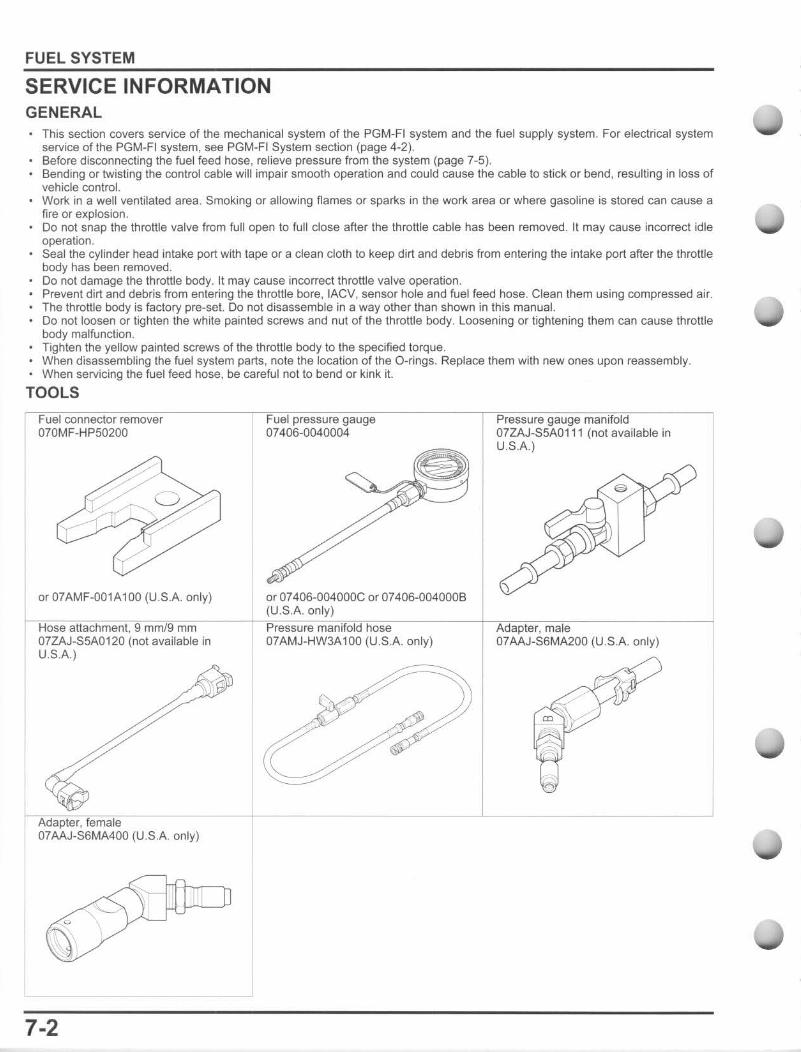
SERVICE INFORMATION GENERAL
This section covers service of the mechanical system of the PGM-FI system and the fuel supply system. For electrical system service of the PGM-FI system, see PGM-Ft System section (page 4-2). Before disconnecting the fuel feed hose, relieve pressure from the system (page 7-5). Bending or twisting the control cable will impair smooth operation and could cause the cable to stick or bend, resulting in loss of vehicle control. Work in a well ventilated area. Smoking or allowing flames or sparks in the work area or where gasoline is stored can cause a fire or explosion . Do nOI snap the throttle valve from full open to full close after the throttle cable has been removed. It may cause incorrect idle operation. Seal the cylinder head intake port with tape or a clean cloth to keep dirt and debris from entering the intake port after the throttle body has been removed. Do not damage the throttle body. It may cause incorrect throttle valve operation. Prevent dirt and debris from entering the throttle bore, IACV, sensor hole and fuel feed hose. Clean them using compressed air. The throttle body is factory pre-set. Do not disassemble in a way other than shown in this manual. Do not loosen or tighten the white painted screws and nut of the throttle body. loosening or tightening them can cause throttle body malfunction. Tighten the yellow painted screws of the throttle body to the specified torque. When disassembling the fuel system parts, note the location of the O-rings. Replace them with new ones upon reassembly. When servicing the fuel feed hose , be careful nolto bend or kink it.
TOOLS
Fuel connector remover 070MF-HP50200
Fuel pressure gauge 0740B-0040004
Pressure gauge manifold 07ZAJ-S5A0111 (not available in U.S.A.)
(U.S.A. only) or 07AMF-001A100 (U .S.A. only~or 07406-004000C or 07406-0040008
Hose attachment, 9 mm/9 mm Pressure manif'~ol"d~h~o~,~e-------1---CA"d<-,~p~le~,~, ~m~'~le;---------~ 07ZAJ-S5A0120 (not available in 07AMJ-HW3A100 (U.S.A. only) 07AAJ-S6MA200 (U .S.A. only) U,SA)
Adapter, female 07AAJ-SBMA400 (U .S.A. only)
7-2
1 ,
1
•
•
j