Electric Service Handbook.pdf
72
Electric Service Handbook June 2012 Commercial/Industrial and Multifamily Projects Permanent & Temporary Service
-
Upload
elmerbarreras -
Category
Documents
-
view
54 -
download
1
Transcript of Electric Service Handbook.pdf
ElectricService
Handbook
June 2012
Commercial/Industrial and Multifamily ProjectsPermanent & Temporary Service

E 2012 by Puget Sound Energy
All rights reserved. No part of this book may be reproduced or transmitted in any form or byany means, electronic or mechanical, including photocopying, recording, or
information storage and retrieval system, without permission from Puget Sound Energy (PSE).
Puget Sound EnergyStandards Department
P.O. Box 97034 EST-07WBellevue, WA 98009-9734
1-888-225-5773

TABLE OF CONTENTS i
ELECTRIC SERVICE HANDBOOK/COMMERCIAL/INDUSTRIAL AND MULTIFAMILY PROJECTS
Table of Contents
PrefaceWhat this handbook contains vii. . . . . . . . . . . . . . . . . . . . . . . . . . . . . . . . . . . . . . . . . . . . . . . . . . . . . .
PSE’s service availability vii. . . . . . . . . . . . . . . . . . . . . . . . . . . . . . . . . . . . . . . . . . . . . . . . . .Glossary of terms used in this handbook vii. . . . . . . . . . . . . . . . . . . . . . . . . . . . . . . . . . . . . .
Electrical service equipment inspection vii. . . . . . . . . . . . . . . . . . . . . . . . . . . . . . . . . . . . . . . . . . . . . .Codes and jurisdictions viii. . . . . . . . . . . . . . . . . . . . . . . . . . . . . . . . . . . . . . . . . . . . . . . . . . . . . . . . . .Scheduling viii. . . . . . . . . . . . . . . . . . . . . . . . . . . . . . . . . . . . . . . . . . . . . . . . . . . . . . . . . . . . . . . . . . . .Other electric service information viii. . . . . . . . . . . . . . . . . . . . . . . . . . . . . . . . . . . . . . . . . . . . . . . . . .How to contact Puget Sound Energy viii. . . . . . . . . . . . . . . . . . . . . . . . . . . . . . . . . . . . . . . . . . . . . . . .PSE’s service providers viii. . . . . . . . . . . . . . . . . . . . . . . . . . . . . . . . . . . . . . . . . . . . . . . . . . . . . . . . . .Overview: New Permanent and Temporary Electric Service Hookup to Existing
PSE Power Facilities for Commercial/Industrial and Multifamily Projects ix. . . . . . . . . . . . . . .
Chapter 1: Steps to a Smooth Permanent Service InstallationThe installation process 1. . . . . . . . . . . . . . . . . . . . . . . . . . . . . . . . . . . . . . . . . . . . . . . . . . . . . . . . . .Setting up an account 1. . . . . . . . . . . . . . . . . . . . . . . . . . . . . . . . . . . . . . . . . . . . . . . . . . . . . . . . . . . .Submitting an application for service 1. . . . . . . . . . . . . . . . . . . . . . . . . . . . . . . . . . . . . . . . . . . . . . .Service voltages 2. . . . . . . . . . . . . . . . . . . . . . . . . . . . . . . . . . . . . . . . . . . . . . . . . . . . . . . . . . . . . . . .Locating other utilities 2. . . . . . . . . . . . . . . . . . . . . . . . . . . . . . . . . . . . . . . . . . . . . . . . . . . . . . . . . . .Cost for service 2. . . . . . . . . . . . . . . . . . . . . . . . . . . . . . . . . . . . . . . . . . . . . . . . . . . . . . . . . . . . . . . .Additional service costs 3. . . . . . . . . . . . . . . . . . . . . . . . . . . . . . . . . . . . . . . . . . . . . . . . . . . . . . . . . .
Voltage flicker and size of transformer 3. . . . . . . . . . . . . . . . . . . . . . . . . . . . . . . . . . . . . . . .Voltage drop calculations 3. . . . . . . . . . . . . . . . . . . . . . . . . . . . . . . . . . . . . . . . . . . . . . . . . .
Chapter 2: Permanent Underground ServicesService equipment installation responsibilities 5. . . . . . . . . . . . . . . . . . . . . . . . . . . . . . . . . . . . . . . .
Puget Sound Energy 5. . . . . . . . . . . . . . . . . . . . . . . . . . . . . . . . . . . . . . . . . . . . . . . . . . . . . .Customer 5. . . . . . . . . . . . . . . . . . . . . . . . . . . . . . . . . . . . . . . . . . . . . . . . . . . . . . . . . . . . . . .
Preparing for your service hookup 5. . . . . . . . . . . . . . . . . . . . . . . . . . . . . . . . . . . . . . . . . . . . . . . . . .Cable limits for transformers 6. . . . . . . . . . . . . . . . . . . . . . . . . . . . . . . . . . . . . . . . . . . . . . . . . . . . . .Customer-provided trenches 7. . . . . . . . . . . . . . . . . . . . . . . . . . . . . . . . . . . . . . . . . . . . . . . . . . . . . .
Trench width for PSE facilities 7. . . . . . . . . . . . . . . . . . . . . . . . . . . . . . . . . . . . . . . . . . . . . .Trench excavating requirements for PSE facilities 8. . . . . . . . . . . . . . . . . . . . . . . . . . . . . . .Trench backfill and restoration 8. . . . . . . . . . . . . . . . . . . . . . . . . . . . . . . . . . . . . . . . . . . . . .
Vault excavation requirements 9. . . . . . . . . . . . . . . . . . . . . . . . . . . . . . . . . . . . . . . . . . . . . . . . . . . . .
Continued on next page

ii TABLE OF CONTENTS
ELECTRIC SERVICE HANDBOOK/COMMERCIAL/INDUSTRIAL AND MULTIFAMILY PROJECTS
Conduit installed at vaults 9. . . . . . . . . . . . . . . . . . . . . . . . . . . . . . . . . . . . . . . . . . . . . . . . . . . . . . . .Attaching a customer’s service line to a power pole 11. . . . . . . . . . . . . . . . . . . . . . . . . . . . . . . . . . . .
When the power pole is on private property 11. . . . . . . . . . . . . . . . . . . . . . . . . . . . . . . . . . . .When the power pole is in a city/county/state right-of-way 11. . . . . . . . . . . . . . . . . . . . . . . .
Racking of cable in vaults 13. . . . . . . . . . . . . . . . . . . . . . . . . . . . . . . . . . . . . . . . . . . . . . . . . . . . . . . .Cable ladder 13. . . . . . . . . . . . . . . . . . . . . . . . . . . . . . . . . . . . . . . . . . . . . . . . . . . . . . . . . . . .Cable supports 13. . . . . . . . . . . . . . . . . . . . . . . . . . . . . . . . . . . . . . . . . . . . . . . . . . . . . . . . . . .Cable training and identification 13. . . . . . . . . . . . . . . . . . . . . . . . . . . . . . . . . . . . . . . . . . . . .
Customer wiring to energized PSE transformers 15. . . . . . . . . . . . . . . . . . . . . . . . . . . . . . . . . . . . . . .Single-phase minipad transformers 15. . . . . . . . . . . . . . . . . . . . . . . . . . . . . . . . . . . . . . . . . . .Three-phase padmount transformers 15. . . . . . . . . . . . . . . . . . . . . . . . . . . . . . . . . . . . . . . . . .
Transformer locations 16. . . . . . . . . . . . . . . . . . . . . . . . . . . . . . . . . . . . . . . . . . . . . . . . . . . . . . . . . . .Landscaping and other obstacles 19. . . . . . . . . . . . . . . . . . . . . . . . . . . . . . . . . . . . . . . . . . . . . . . . . . .Working space 19. . . . . . . . . . . . . . . . . . . . . . . . . . . . . . . . . . . . . . . . . . . . . . . . . . . . . . . . . . . . . . . . .Guard posts for padmount and subsurface equipment 20. . . . . . . . . . . . . . . . . . . . . . . . . . . . . . . . . . .
Approved guard posts 21. . . . . . . . . . . . . . . . . . . . . . . . . . . . . . . . . . . . . . . . . . . . . . . . . . . .Fault current levels 22. . . . . . . . . . . . . . . . . . . . . . . . . . . . . . . . . . . . . . . . . . . . . . . . . . . . . . . . . . . . . .
Chapter 3: Permanent Overhead ServicesService equipment installation responsibilities 25. . . . . . . . . . . . . . . . . . . . . . . . . . . . . . . . . . . . . . . .
Puget Sound Energy 25. . . . . . . . . . . . . . . . . . . . . . . . . . . . . . . . . . . . . . . . . . . . . . . . . . . . . .Customer 25. . . . . . . . . . . . . . . . . . . . . . . . . . . . . . . . . . . . . . . . . . . . . . . . . . . . . . . . . . . . . . .
Preparing for your service hookup 25. . . . . . . . . . . . . . . . . . . . . . . . . . . . . . . . . . . . . . . . . . . . . . . . . .Service mast requirements 26. . . . . . . . . . . . . . . . . . . . . . . . . . . . . . . . . . . . . . . . . . . . . . . . . . . . . . . .
Height requirements 26. . . . . . . . . . . . . . . . . . . . . . . . . . . . . . . . . . . . . . . . . . . . . . . . . . . . . .Clearances from gas meters 26. . . . . . . . . . . . . . . . . . . . . . . . . . . . . . . . . . . . . . . . . . . . . . . .Additional mast supports 26. . . . . . . . . . . . . . . . . . . . . . . . . . . . . . . . . . . . . . . . . . . . . . . . . .
Screw-in service knobs 26. . . . . . . . . . . . . . . . . . . . . . . . . . . . . . . . . . . . . . . . . . . . . . . . . . . . . . . . . .Installing the service equipment 27. . . . . . . . . . . . . . . . . . . . . . . . . . . . . . . . . . . . . . . . . . . . . . . . . . .
List of customer-provided service entrance equipment 27. . . . . . . . . . . . . . . . . . . . . . . . . . .Terrain considerations for meter base/socket locations 27. . . . . . . . . . . . . . . . . . . . . . . . . . .
Customer-owned meter pole 27. . . . . . . . . . . . . . . . . . . . . . . . . . . . . . . . . . . . . . . . . . . . . . . . . . . . . .Meter pole requirements 27. . . . . . . . . . . . . . . . . . . . . . . . . . . . . . . . . . . . . . . . . . . . . . . . . . .Meter pole locations 27. . . . . . . . . . . . . . . . . . . . . . . . . . . . . . . . . . . . . . . . . . . . . . . . . . . . . .Meter pole installation 28. . . . . . . . . . . . . . . . . . . . . . . . . . . . . . . . . . . . . . . . . . . . . . . . . . . .
Chapter 4: Meter Installation
Section 1: General Metering Requirements
Metering equipment responsibilities 29. . . . . . . . . . . . . . . . . . . . . . . . . . . . . . . . . . . . . . . . . . . . . . . .Puget Sound Energy 29. . . . . . . . . . . . . . . . . . . . . . . . . . . . . . . . . . . . . . . . . . . . . . . . . . . . . .Customer 29. . . . . . . . . . . . . . . . . . . . . . . . . . . . . . . . . . . . . . . . . . . . . . . . . . . . . . . . . . . . . . .
Other customer responsibilities 30. . . . . . . . . . . . . . . . . . . . . . . . . . . . . . . . . . . . . . . . . . . . . . . . . . . .Installing or removing meters by a qualified electrician 30. . . . . . . . . . . . . . . . . . . . . . . . . .Inspections and approvals 30. . . . . . . . . . . . . . . . . . . . . . . . . . . . . . . . . . . . . . . . . . . . . . . . . .

TABLE OF CONTENTS iii
ELECTRIC SERVICE HANDBOOK/COMMERCIAL/INDUSTRIAL AND MULTIFAMILY PROJECTS
Sealing provisions on enclosures 30. . . . . . . . . . . . . . . . . . . . . . . . . . . . . . . . . . . . . . . . . . . .Service conductors 30. . . . . . . . . . . . . . . . . . . . . . . . . . . . . . . . . . . . . . . . . . . . . . . . . . . . . . .Grounding 30. . . . . . . . . . . . . . . . . . . . . . . . . . . . . . . . . . . . . . . . . . . . . . . . . . . . . . . . . . . . . .Customer equipment 30. . . . . . . . . . . . . . . . . . . . . . . . . . . . . . . . . . . . . . . . . . . . . . . . . . . . . .Current-limiting fuses 30. . . . . . . . . . . . . . . . . . . . . . . . . . . . . . . . . . . . . . . . . . . . . . . . . . . . .
Meter locations 31. . . . . . . . . . . . . . . . . . . . . . . . . . . . . . . . . . . . . . . . . . . . . . . . . . . . . . . . . . . . . . . . .Preferred locations 31. . . . . . . . . . . . . . . . . . . . . . . . . . . . . . . . . . . . . . . . . . . . . . . . . . . . . . .Locations to avoid 31. . . . . . . . . . . . . . . . . . . . . . . . . . . . . . . . . . . . . . . . . . . . . . . . . . . . . . . .Meter location requirements for manufactured commercial structures(school portables, industrial modular office, etc.) 31. . . . . . . . . . . . . . . . . . . . . . . . . . . . . . .
Electrical equipment room requirements 32. . . . . . . . . . . . . . . . . . . . . . . . . . . . . . . . . . . . . . . . . . . . .Meter room locations in high-rise buildings 33. . . . . . . . . . . . . . . . . . . . . . . . . . . . . . . . . . . . . . . . . .Meter bases/sockets 33. . . . . . . . . . . . . . . . . . . . . . . . . . . . . . . . . . . . . . . . . . . . . . . . . . . . . . . . . . . . .
General requirements 33. . . . . . . . . . . . . . . . . . . . . . . . . . . . . . . . . . . . . . . . . . . . . . . . . . . . .Determining meter base/socket type 34. . . . . . . . . . . . . . . . . . . . . . . . . . . . . . . . . . . . . . . . . .Meter base/socket clearances 34. . . . . . . . . . . . . . . . . . . . . . . . . . . . . . . . . . . . . . . . . . . . . . .
Remote metering 36. . . . . . . . . . . . . . . . . . . . . . . . . . . . . . . . . . . . . . . . . . . . . . . . . . . . . . . . . . . . . . .Meter pedestal requirements for remote metering 36. . . . . . . . . . . . . . . . . . . . . . . . . . . . . . .Meter pedestal location 37. . . . . . . . . . . . . . . . . . . . . . . . . . . . . . . . . . . . . . . . . . . . . . . . . . . .Remote service requirements based on service ampacity 37. . . . . . . . . . . . . . . . . . . . . . . . . .
Multiple meter installations 38. . . . . . . . . . . . . . . . . . . . . . . . . . . . . . . . . . . . . . . . . . . . . . . . . . . . . . .Multifamily 38. . . . . . . . . . . . . . . . . . . . . . . . . . . . . . . . . . . . . . . . . . . . . . . . . . . . . . . . . . . . .Nonresidential 39. . . . . . . . . . . . . . . . . . . . . . . . . . . . . . . . . . . . . . . . . . . . . . . . . . . . . . . . . . .Multiple meter base/socket labeling 39. . . . . . . . . . . . . . . . . . . . . . . . . . . . . . . . . . . . . . . . . .
Section 2: Self-Contained Metering RequirementsSingle-phase services: 400 A or less and Three-phase services: 200 A or less
Meter base/socket main disconnect combinations 40. . . . . . . . . . . . . . . . . . . . . . . . . . . . . . . . . . . . . .Manual block bypass requirements 40. . . . . . . . . . . . . . . . . . . . . . . . . . . . . . . . . . . . . . . . . . .Disconnecting means 40. . . . . . . . . . . . . . . . . . . . . . . . . . . . . . . . . . . . . . . . . . . . . . . . . . . . .Safety sockets 40. . . . . . . . . . . . . . . . . . . . . . . . . . . . . . . . . . . . . . . . . . . . . . . . . . . . . . . . . . .
Load balancing 40. . . . . . . . . . . . . . . . . . . . . . . . . . . . . . . . . . . . . . . . . . . . . . . . . . . . . . . . . . . . . . . . .Service conductor connections 40. . . . . . . . . . . . . . . . . . . . . . . . . . . . . . . . . . . . . . . . . . . . . . . . . . . . .Self-contained meter base/socket requirements 43. . . . . . . . . . . . . . . . . . . . . . . . . . . . . . . . . . . . . . . .
Single-phase services: 400 A or less 43. . . . . . . . . . . . . . . . . . . . . . . . . . . . . . . . . . . . . . . . . .Single-phase services: 200 A or less 43. . . . . . . . . . . . . . . . . . . . . . . . . . . . . . . . . . . . . . . . . .Single-phase services: 201 to 400 A 43. . . . . . . . . . . . . . . . . . . . . . . . . . . . . . . . . . . . . . . . . .Single-phase services: 120/208 V, 200 A or less 43. . . . . . . . . . . . . . . . . . . . . . . . . . . . . . . .Single-phase streetlight services: 120/240 V or 240/480 V pedestals 43. . . . . . . . . . . . . . . .
Three-phase services: 200 A or less 43. . . . . . . . . . . . . . . . . . . . . . . . . . . . . . . . . . . . . . . . . . . . . . . . .All three-phase services 43. . . . . . . . . . . . . . . . . . . . . . . . . . . . . . . . . . . . . . . . . . . . . . . . . . .Three-phase services: 120/240 V, four-wire delta(Restricted — available only for existing services) 44. . . . . . . . . . . . . . . . . . . . . . . . . . . . . .Three-phase services: 277/480 V 44. . . . . . . . . . . . . . . . . . . . . . . . . . . . . . . . . . . . . . . . . . . .

iv TABLE OF CONTENTS
ELECTRIC SERVICE HANDBOOK/COMMERCIAL/INDUSTRIAL AND MULTIFAMILY PROJECTS
Section 3: Current Transformer (CT) Metering Requirements (up to 800 A)Single-phase services: over 400 A and Three-phase services: over 200 A
Puget Sound Energy’s installation responsibilities 45. . . . . . . . . . . . . . . . . . . . . . . . . . . . . . . . . . . . .Customer’s installation responsibilities 45. . . . . . . . . . . . . . . . . . . . . . . . . . . . . . . . . . . . . . . . . . . . . .
Meter base/socket 45. . . . . . . . . . . . . . . . . . . . . . . . . . . . . . . . . . . . . . . . . . . . . . . . . . . . . . . .Metering circuit conduit 45. . . . . . . . . . . . . . . . . . . . . . . . . . . . . . . . . . . . . . . . . . . . . . . . . . .CT enclosure 46. . . . . . . . . . . . . . . . . . . . . . . . . . . . . . . . . . . . . . . . . . . . . . . . . . . . . . . . . . . .Mounting the CT 47. . . . . . . . . . . . . . . . . . . . . . . . . . . . . . . . . . . . . . . . . . . . . . . . . . . . . . . . .
Customer requirements for switchboard metering (over 800 A) 49. . . . . . . . . . . . . . . . . . . . . . . . . . . .Approval drawings required 49. . . . . . . . . . . . . . . . . . . . . . . . . . . . . . . . . . . . . . . . . . . . . . . .Three-phase services 49. . . . . . . . . . . . . . . . . . . . . . . . . . . . . . . . . . . . . . . . . . . . . . . . . . . . . .
Chapter 5: Temporary ServicesWhat this chapter contains 51. . . . . . . . . . . . . . . . . . . . . . . . . . . . . . . . . . . . . . . . . . . . . . . . . . . . . . . .Three-phase temporary service 51. . . . . . . . . . . . . . . . . . . . . . . . . . . . . . . . . . . . . . . . . . . . . . . . . . . .Definition 51. . . . . . . . . . . . . . . . . . . . . . . . . . . . . . . . . . . . . . . . . . . . . . . . . . . . . . . . . . . . . . . . . . . . .Obtaining your temporary service from existing power facilities 51. . . . . . . . . . . . . . . . . . . . . . . . . .Scheduling 52. . . . . . . . . . . . . . . . . . . . . . . . . . . . . . . . . . . . . . . . . . . . . . . . . . . . . . . . . . . . . . . . . . . .Customer charge for service 52. . . . . . . . . . . . . . . . . . . . . . . . . . . . . . . . . . . . . . . . . . . . . . . . . . . . . . .Temporary meter base/socket requirements 52. . . . . . . . . . . . . . . . . . . . . . . . . . . . . . . . . . . . . . . . . . .Temporary underground services 52. . . . . . . . . . . . . . . . . . . . . . . . . . . . . . . . . . . . . . . . . . . . . . . . . . .
Meter location 53. . . . . . . . . . . . . . . . . . . . . . . . . . . . . . . . . . . . . . . . . . . . . . . . . . . . . . . . . . .Trenching and excavation requirements 53. . . . . . . . . . . . . . . . . . . . . . . . . . . . . . . . . . . . . . .Underground temporary service installation process 54. . . . . . . . . . . . . . . . . . . . . . . . . . . . .
Temporary overhead services 56. . . . . . . . . . . . . . . . . . . . . . . . . . . . . . . . . . . . . . . . . . . . . . . . . . . . . .Meter location 56. . . . . . . . . . . . . . . . . . . . . . . . . . . . . . . . . . . . . . . . . . . . . . . . . . . . . . . . . . .Service line path requirements 56. . . . . . . . . . . . . . . . . . . . . . . . . . . . . . . . . . . . . . . . . . . . . .Clearance requirements 56. . . . . . . . . . . . . . . . . . . . . . . . . . . . . . . . . . . . . . . . . . . . . . . . . . . .Overhead temporary service installation process 57. . . . . . . . . . . . . . . . . . . . . . . . . . . . . . . .
Glossary 59. . . . . . . . . . . . . . . . . . . . . . . . . . . . . . . . . . . . . . . . . . . . . . . . . . . . . . . . . . . . . . . . . . . . .

TABLE OF CONTENTS v
ELECTRIC SERVICE HANDBOOK/COMMERCIAL/INDUSTRIAL AND MULTIFAMILY PROJECTS
List of TablesTable 1 Service voltages available from PSE 2. . . . . . . . . . . . . . . . . . . . . . . . . . . . . . . . . . . . . .
Table 2 Color codes for locating utilities 2. . . . . . . . . . . . . . . . . . . . . . . . . . . . . . . . . . . . . . . . .
Table 3 Maximum cable runs per transformer 6. . . . . . . . . . . . . . . . . . . . . . . . . . . . . . . . . . . . .
Table 4 Clearances for padmount transformers 16. . . . . . . . . . . . . . . . . . . . . . . . . . . . . . . . . . . .
Table 5 Maximum short circuit current (in amps) for single-phase transformers,padmounted 22. . . . . . . . . . . . . . . . . . . . . . . . . . . . . . . . . . . . . . . . . . . . . . . . . . . . . . . . .
Table 6 Maximum short circuit current (in amps) for three-phase transformers,padmounted 22. . . . . . . . . . . . . . . . . . . . . . . . . . . . . . . . . . . . . . . . . . . . . . . . . . . . . . . . .
Table 7 Maximum short circuit current (in amps) for Y-Y grounded transformers 23. . . . . . . . .
Table 8 Single-phase (nonresidential only) and all three-phase meter base/socket types 44. . . . .
Table 9 CT enclosure dimensions (minimum) 46. . . . . . . . . . . . . . . . . . . . . . . . . . . . . . . . . . . . .
List of FiguresFigure 1 Typical joint utility trench with primary voltage cable on your private property 7. . . .
Figure 2 Location of customer conduit in PSE vaults 9. . . . . . . . . . . . . . . . . . . . . . . . . . . . . . . .
Figure 3 Minimum dimensions and excavation requirements for a small, secondaryconnection handhole 10. . . . . . . . . . . . . . . . . . . . . . . . . . . . . . . . . . . . . . . . . . . . . . . . . . .
Figure 4 Minimum dimensions and excavation requirements for a single-phase padmounttransformer vault 10. . . . . . . . . . . . . . . . . . . . . . . . . . . . . . . . . . . . . . . . . . . . . . . . . . . . .
Figure 5 Minimum dimensions and excavation requirements for a three-phase padmounttransformer vault, 300 kVA or less 11. . . . . . . . . . . . . . . . . . . . . . . . . . . . . . . . . . . . . . . .
Figure 6 PVC conduit riser placement when pole is on private property only 12. . . . . . . . . . . . .
Figure 7 PSE-installed underground connection handhole 13. . . . . . . . . . . . . . . . . . . . . . . . . . . . .
Figure 8 Minimum dimensions and excavation requirements for a three-phase padmounttransformer vault, 500 kVA and larger 14. . . . . . . . . . . . . . . . . . . . . . . . . . . . . . . . . . . . .
Figure 9 Racking of cable in vaults 14. . . . . . . . . . . . . . . . . . . . . . . . . . . . . . . . . . . . . . . . . . . . . .
Figure 10 Clearances for transformers from structures 17. . . . . . . . . . . . . . . . . . . . . . . . . . . . . . . .
Figure 11 Clearances for transformers 18. . . . . . . . . . . . . . . . . . . . . . . . . . . . . . . . . . . . . . . . . . . . .
Figure 12 Minimum clearances from oil-filled equipment to LP, hazardous liquid,or fuel tanks 18. . . . . . . . . . . . . . . . . . . . . . . . . . . . . . . . . . . . . . . . . . . . . . . . . . . . . . . . .
Figure 13 Plan view of subsurface equipment clear working space 19. . . . . . . . . . . . . . . . . . . . . . .
Figure 14 Plan view of padmount equipment clear working space 19. . . . . . . . . . . . . . . . . . . . . . .
Figure 15 Guard post location requirements 20. . . . . . . . . . . . . . . . . . . . . . . . . . . . . . . . . . . . . . . . .
Figure 16 Typical guard posts 21. . . . . . . . . . . . . . . . . . . . . . . . . . . . . . . . . . . . . . . . . . . . . . . . . . . .
Figure 17 Permanent overhead meter pole installation 28. . . . . . . . . . . . . . . . . . . . . . . . . . . . . . . .
Figure 18 Typical 8 in. x 8 in. x 6 in. exterior wall-mounted AMR antenna installations 33. . . . . .
Figure 19 Meter base/socket minimum clearances 35. . . . . . . . . . . . . . . . . . . . . . . . . . . . . . . . . . . .
Figure 20 Minimum clearances for recessed meters 35. . . . . . . . . . . . . . . . . . . . . . . . . . . . . . . . . . .
Figure 21 Typical factory-built residential multimeter assembly for multifamily complex 38. . . .
Continued on next page

vi TABLE OF CONTENTS
ELECTRIC SERVICE HANDBOOK/COMMERCIAL/INDUSTRIAL AND MULTIFAMILY PROJECTS
Figure 22 Typical multiple nonresidential meter installations for services 200 A or less 39. . . . . .
Figure 23 Typical safety socket 41. . . . . . . . . . . . . . . . . . . . . . . . . . . . . . . . . . . . . . . . . . . . . . . . . .
Figure 24 Typical arrangement of service conductors for underground commercialsingle-phase 320 A service 41. . . . . . . . . . . . . . . . . . . . . . . . . . . . . . . . . . . . . . . . . . . . . .
Figure 25 Typical arrangement of service conductors for overhead commercialsingle-phase 320 A service 42. . . . . . . . . . . . . . . . . . . . . . . . . . . . . . . . . . . . . . . . . . . . . .
Figure 26 Typical arrangement of service conductors for 120/208 V three-phaseself-contained 200 A service 42. . . . . . . . . . . . . . . . . . . . . . . . . . . . . . . . . . . . . . . . . . . .
Figure 27 Preferred method of conduit installation in a single-phase and three-phaseCT enclosure 46. . . . . . . . . . . . . . . . . . . . . . . . . . . . . . . . . . . . . . . . . . . . . . . . . . . . . . . . .
Figure 28 Single-phase CT mounting base bracket. EUSERC 328A or 328B 47. . . . . . . . . . . . . .
Figure 29 Three-phase CT mounting base bracket. EUSERC 329A or 329B 48. . . . . . . . . . . . . . .
Figure 30 Options for switchboard meters 49. . . . . . . . . . . . . . . . . . . . . . . . . . . . . . . . . . . . . . . . . .
Figure 31 Instrument-rated CT meter bases/sockets 49. . . . . . . . . . . . . . . . . . . . . . . . . . . . . . . . . . .
Figure 32 Trenching requirements for power stubout 53. . . . . . . . . . . . . . . . . . . . . . . . . . . . . . . . .
Figure 33 Temporary underground service installation 55. . . . . . . . . . . . . . . . . . . . . . . . . . . . . . . .
Figure 34 Minimum clearance requirements upon installation 57. . . . . . . . . . . . . . . . . . . . . . . . . .
Figure 35 Temporary overhead service installation 58. . . . . . . . . . . . . . . . . . . . . . . . . . . . . . . . . . .
Back PocketExcavation Requirements for Joint Utility Mainline Trench Form 2809. . . . . . . . . . . . . . . . . . . . . . . . . . . . . .Installation Requirements for Underground Services Form 3061. . . . . . . . . . . . . . . . . . . . . . . . . . . . . . . . . . .
PREFACE vii
ELECTRIC SERVICE HANDBOOK/COMMERCIAL/INDUSTRIAL AND MULTIFAMILY PROJECTS
Preface
This handbook is your guide to Puget Sound Energy’s (PSE) requirements for newelectric service installations of less than 600 volts for commercial, industrial,multifamily, and nonresidential applications.
This handbook provides most, but not all, of the information and requirements that youwill need. It does not include all possible standards and specifications required by PSE,state, federal, or local code requirements. If you need additional information, please callPSE Customer Service at 1-888-225-5773, your local government agency, or stateinspector.
What this handbook contains
This handbook contains information on service installations for:
H Commercial and industrial buildings
H Apartment complexes
H Community wells
H Condominium complexes
H Barns and shops
If the type of service you need is not addressed in this handbook, please contact PSE’sCustomer Construction Services (CCS) at 1-888-321-7779.
PSE’s service availability
General boundaries for PSE’s gas and electric service territory are available on PSE.com.A CCS Representative can help you to determine the closest available service line andcan provide you with cost information for establishing new service.
Glossary of terms used in this handbook
For your convenience, glossary words appear in bold italics throughout the text the firsttime they appear (e.g., meter pole).
Electrical service equipment inspection
Once your service equipment is installed, the State of Washington or the city withjurisdiction over your area requires that your installation pass an electrical inspectionbefore PSE can connect you to the system. It is your responsibility to request thisinspection.
PREFACEviii
ELECTRIC SERVICE HANDBOOK/COMMERCIAL/INDUSTRIAL AND MULTIFAMILY PROJECTS
Codes and jurisdictions
This handbook shall not be interpreted to conflict with the regulations of the State ofWashington or other regulatory bodies having jurisdiction. PSE’s metering requirementsmay be more stringent. Local codes and requirements related to the planned work shouldbe addressed before any construction begins.
Scheduling
Engineering, scheduling, and construction of the work will vary depending upon thecomplexity of the job and the volume of work requested by PSE customers. Contact yourCCS Representative at 1-888-321-7779 for current construction scheduling.
Other electric service information
Any of Puget Sound Energy’s handbooks are available, free of charge, from PSE.
How to contact Puget Sound Energy
Please direct any technical questions regarding the information in this booklet, to PSE’sCustomer Construction Services Department at 1-888-321-7779.
You may also visit PSE.com, our web site for online applications, construction videos,and energy efficiency programs, as well as other helpful information.
If you have any general billing questions regarding your account or questions about gasor electric service installation, please call Customer Service at 1-888-225-5773.
PSE’s service providers
PSE contracts with two partner companies to provide construction and engineeringservices: Potelco, Inc. and InfraSource Construction LLC. The project manager and theemployees who install your service may work for these service providers on PSE’sbehalf.

This information applies only if PSE has existing power facilities in your area.If electric power is not readily available, please call:
CUSTOMER CONSTRUCTION SERVICES
1-888-321-7779
Customer Responsibilities:
H Determine if you need overhead or underground service.
H Contact PSE to establish an account, and order your service.
H Obtain an electrical work permit.
H Determine the service rating you want (for example, 200 A or 400 A).
H Determine an approved meter location.
H Notify other utilities of your project.
H Ensure that existing underground utilities are located before you dig. Call 811 at least twoworking days before you dig.
H Prepare job site by providing a clear path/trench for your service line for proper vaultentrance requirements per PSE standards.
H Obtain an approved electrical inspection.
H After the electrical inspection has been completed and approved, request PSE to install andenergize your system.
Puget Sound Energy’s Responsibilities:
H Determine if engineering is required.
H Install your overhead or underground permanent service line conductors.
H Install your meter and energize your system.
Scheduling:
H If engineering is not required, services are typically energized 3 to 5 days after you havepassed your inspection.
Service Charge:
H Charges vary due to the type of service you request and the type of system we have in yourarea. Contact your CCS Representative for current rate information.
PREFACE ix
ELECTRIC SERVICE HANDBOOK/COMMERCIAL/INDUSTRIAL AND MULTIFAMILY PROJECTS
w Electric ServiceHoo
Overview:New Permanent and Temporary Electric Service Hookup
to Existing PSE Power Facilitiesfor Commercial/Industrial and Multifamily Projects

PREFACEx
ELECTRIC SERVICE HANDBOOK/COMMERCIAL/INDUSTRIAL AND MULTIFAMILY PROJECTS
STEPS TO A SMOOTH PERMANENT SERVICE INSTALLATION 1
ELECTRIC SERVICE HANDBOOK/COMMERCIAL/INDUSTRIAL AND MULTIFAMILY PROJECTS CHAPTER 1
Chapter 1
Steps to a Smooth Permanent ServiceInstallation
The installation process
Before a permanent service is energized, you are required to complete the following:
H Establish an account with PSE by calling Customer Service at 1-888-225-5773.
H Determine the type of service needed and if that service will be underground oroverhead.
H Install required service equipment and underground service cable (if applicable).
H Obtain an electrical inspection.
H Call PSE and request that your service be energized.
Setting up an account
Before PSE can provide new service, you must establish an account. Simply callCustomer Service at 1-888-225-5773. They will request billing information and theaddress for the new service from you. If you wish, we can initiate your temporary serviceorder at the same time.
Submitting an application for service
Call Customer Construction Services (CCS) at 1-888-321-7779 and submit ElectricService Application Permanent Non-Residential 201E (Form 1378) or Electric ServiceMulti-Family Development 400E (Form 4409). All forms can be downloaded atPSE.com.
When you fill out the application, make sure that it is as complete as possible, andinclude a copy of each of the following items (if applicable) with the application:
H Legal description of the property
H Title insurance policy, recorded warranty deed, or real estate contract
H Site plan
H Landscaping plan
H Water main plan
H Sewer main and profile plans
H Road and storm drainage plan
H Road cross-section plan
H Streetlight requirements
NOTE: Several of the above plans may be included in one drawing.

STEPS TO A SMOOTH PERMANENT SERVICE INSTALLATION2
ELECTRIC SERVICE HANDBOOK/COMMERCIAL/INDUSTRIAL AND MULTIFAMILY PROJECTSCHAPTER 1
Service voltagesWe offer the following standard voltages for nonresidential customers:
Table 1 Service voltages available from PSE
Service Type Voltage
Single-phase 120/208 V, 3 wire *120/240 V, 3 wire †
Three-phase 120/208 V, 4 wire277/480 V, 4 wire
* Available only if 120/208 secondary voltage exists at the location at the time youapply for service.
† Available for loads up to a maximum demand of 100 kW.
Locating other utilities
Before any digging project, contact the 811 “Call Before You Dig” hotline two businessdays before digging. The “Call Before You Dig” law requires anyone digging into theground to call and have underground utilities located to avoid potential hazards withstriking or digging up utility lines.
The utility locate service is free and necessary. The utility locate service will locate theunderground facilities owned by the member utilities in your area. The locate serviceuses the following color codes to identify underground utilities:
Table 2 Color codes for locating utilities
Color Utility
White Proposed excavation
Pink Temporary survey markings
Red Electric power lines, cables, conduit, and lighting cables
Yellow Gas, oil, steam, petroleum, or gaseous materials
Orange Communication, alarm or signal lines, cables, or conduit
Blue Potable water
Purple Reclaimed water, irrigation, and slurry lines
Green Sewers and drain lines
NOTE: Use white paint to mark the area within which you want utility locations.
Once all utilities are located:
H Do not dig with machinery closer than 24 inches from the locate marks.
H Hand dig to expose all utilities to be crossed.
Cost for serviceContact your CCS Representative to determine the cost for service.
STEPS TO A SMOOTH PERMANENT SERVICE INSTALLATION 3
ELECTRIC SERVICE HANDBOOK/COMMERCIAL/INDUSTRIAL AND MULTIFAMILY PROJECTS CHAPTER 1
Additional service costs
Voltage flicker and size of transformer
Commercial/industrial customers—If the system will serve a facility that is purposelybuilt to serve a single specific customer, and that customer will operate the facility and isknowledgeable about flicker, then the system shall be designed to deliver no more than3 percent voltage flicker at the point of service.
Multifamily customers—If a transformer is built to serve multiple customers, amaximum of 3 percent or less is specified at the point of service. This is common to allcustomers.
In your Application for Service (Form 1378, 4414, or 4409), you must provide PSE withthe locked rotor starting currents for the largest single-phase and three-phase motors.After we determine the size of transformer required to serve the new load of the facility,we will calculate the percent voltage flicker (from the motor’s starting current) at thepoint of service and provide that number to you.
If this voltage dip exceeds PSE’s limits based on facility type, the transformer size mustbe increased to compensate for this. You will be responsible for the difference in cost ofthe larger transformer, or you will need to install sufficient controls to bring flicker backwithin PSE’s limits.
NOTE:We will size PSE’s facilities to provide a level of voltage flicker that is normallyacceptable to customers. If you need to be served with a higher quality of service, contactyour CCS Representative.
Voltage drop calculations
You are responsible for calculating the overall voltage drop to your facility anddetermining what is an acceptable level for your facility. If you determine that thevoltage drop is unacceptable, you must determine a solution. Some possiblesolutions are:
H Run separate services from PSE’s transformer for motor loads.
H Modify or upgrade your equipment or underground service cables (if applicable).
H Pay PSE to increase the size of our transformer.
H Pay PSE to provide a second transformer.

STEPS TO A SMOOTH PERMANENT SERVICE INSTALLATION4
ELECTRIC SERVICE HANDBOOK/COMMERCIAL/INDUSTRIAL AND MULTIFAMILY PROJECTSCHAPTER 1

PERMANENT UNDERGROUND SERVICES 5
ELECTRIC SERVICE HANDBOOK/COMMERCIAL/INDUSTRIAL AND MULTIFAMILY PROJECTS CHAPTER 2
Chapter 2
Permanent Underground Services
This chapter provides you with information on PSE’s underground service installation.Please follow these requirements to avoid a delay in your service hookup. If you haveany questions about this information, call Customer Construction Services (CCS) at1-888-321-7779.
Service equipment installation responsibilities
Puget Sound Energy
PSE is responsible for furnishing, installing, and maintaining the primary voltage systemequipment. This equipment includes primary conduit and cables, service conductorconnectors at the transformer, current transformers, meter(s), and meter wiring.
CustomerYou are responsible for furnishing, installing, and maintaining all required serviceentrance equipment, including the service entrance conduits* from the meter socket orcurrent transformer enclosure to PSE’s designated point of delivery.
For services where current transformers (CTs) are required, you will also need to runconduit from the CT enclosure to the meter base. Refer to Chapter 4, Section 3, CurrentTransformer (CT) Metering (up to 800 amps) for more information.
NOTE: PSE will supply, install, and maintain the CTs and meter wiring.
* DO NOT run a grounding wire to PSE’s point of connection at the transformer orhandhole. PSE will not connect it.
Preparing for your service hookup
The following list will help you prepare your project for the installation of anunderground service. After you complete these items, PSE will connect your service andinstall the metering equipment.
1. Check for any local ordinances/covenants that may prevent you from obtaining anunderground service.
2. Complete Electric Service Application Permanent Non-Residential 201E (Form 1378)or Electric Service Multi-Family Development 400E (Form 4409).
3. Supply site drawings and load information to your CCS Representative (refer toChapter 1, Submitting an Application for Service).
4. Contact CCS to determine where your underground service will originate.
Continued on next page

PERMANENT UNDERGROUND SERVICES6
ELECTRIC SERVICE HANDBOOK/COMMERCIAL/INDUSTRIAL AND MULTIFAMILY PROJECTSCHAPTER 2
5. Determine an approved meter location (refer to Chapter 4, Section 1, GeneralMetering Requirements, Meter locations section).
6. If required by CCS, provide an easement for any permanently installed PSEequipment located on your property.
7. Provide payment for any preconstruction costs determined by your CCSRepresentative.
8. Provide all excavation for PSE’s facilities and get an approval for the proper vaultentrance location of your conductor/conduit.
9. Provide service conductors.
10. Install required service entrance equipment.
11. Connect the meter sockets and permanently label them to indicate the part of thepremises they serve, such as unit number.
12. Obtain an approved electrical inspection.
13. Call CCS at 1-888-321-7779 to initiate a connection and energize your newservice.
Cable limits for transformers
The maximum number of secondary conductors allowed for a specific transformer size islimited to those listed below in Table 3.
Table 3 Maximum cable runs per transformer
Transformer Size and Voltage(PSE-provided)
Maximum Allowed Cable Runs(Customer-provided)
45 thru 300 kVA,120/208 V secondary
12 Runs #2 -- 500 mcm OR10 Runs 501 -- 750 mcm
45 thru 300 kVA,277/480 V secondary
12 Runs #2 --- 500 mcm OR10 Runs 501 --- 750 mcm
500 thru 750 kVA,120/208 V secondary
18 Runs #2 -- 500 mcm OR14 Runs 501 -- 750 mcm
500 thru 750 kVA,277/480 V secondary
12 Runs #2 --- 500 mcm OR10 Runs 501 --- 750 mcm
1000 kVA,120/208 V secondary
24 Runs #2 -- 500 mcm OR18 Runs 501 -- 750 mcm
1000 kVA,277/480 V secondary
18 Runs #2 --- 500 mcm OR14 Runs 501 --- 750 mcm
1500 thru 2500 kVA,277/480 V secondary
24 Runs #2 --- 500 mcm OR18 Runs 501 --- 750 mcm
PERMANENT UNDERGROUND SERVICES 7
ELECTRIC SERVICE HANDBOOK/COMMERCIAL/INDUSTRIAL AND MULTIFAMILY PROJECTS CHAPTER 2
Customer-provided trenches
Trench width for PSE facilities
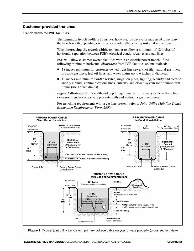
The minimum trench width is 18 inches; however, the excavator may need to increasethe trench width depending on the other conduits/lines being installed in the trench.
When increasing the trench width, remember to allow a minimum of 12 inches ofhorizontal separation between PSE’s electrical conduits/cables and gas lines.
PSE will allow customer-owned facilities within an electric power trench, if thefollowing minimum horizontal clearances from PSE facilities are maintained:
H 18 inches minimum for customer-owned tight-line sewer (not tile), natural gas lines,propane gas lines, fuel oil lines, and water mains up to 6 inches in diameter.
H 12 inches minimum for water service, irrigation pipes, lighting, security and electricsupply circuits, communications lines, culverts, and closed system roof drains/stormdrains (not French drains).
Figure 1 illustrates PSE’s width and depth requirements for primary cable voltage lineextension trenches on private property with and without a gas line present.
For trenching requirements with a gas line present, refer to Joint Utility Mainline TrenchExcavation Requirements (Form 2809).
24I Min
Final Grade
32I Typical(Power, Gas, and Communications)
Communications
Primary PowerCables or Conduit
Gas
ExcavatedDirt Pile
4I MinSeparation
12I MinSeparation
ROADSIDE
36I MinCover
48IMax.
4I Sand Bedding
6I Sand Shading
Backfill(No rocks over 6I diameter)
NOTE: Install 12I sand shading if thebackfill contains rocks greater than 6I dia.
12I MinSeparation
PRIMARY POWER CABLEIn Conduit Installation
Final Grade
36IMinCover
Backfill forConduit
(No Rocks over6I Diameter)
Phone & TV
4I MinSeparation48I
Max.
ROADSIDE
Primary Power CableDirect Buried
3I of sand, 5/8I minus, or clean backfill shading
PRIMARY POWER CABLEDirect Buried Installation
Final Grade
36IMinCover
24I Min(To Excavated Dirt Pile)
Backfill forDirect Bury(No Rocks over6I Diameter)
Phone & TV
4I MinSeparation
48IMax.
ROADSIDE
Primary Power Cablein Conduit
24I Min(To Excavated Dirt Pile)
18ITypical
4I of sand, 5/8I minus, or clean backfill bedding
PRIMARY POWER CABLEWith Gas and Communications
Figure 1 Typical joint utility trench with primary voltage cable on your private property (cross-section view)
PERMANENT UNDERGROUND SERVICES8
ELECTRIC SERVICE HANDBOOK/COMMERCIAL/INDUSTRIAL AND MULTIFAMILY PROJECTSCHAPTER 2
Trench excavating requirements for PSE facilities
The following requirements for the trench must be met before power conduits/cables willbe installed.
H When you trench in the right-of-way on PSE’s behalf, the governing jurisdictionsissue public roadway use permits to PSE. PSE requires that you provide a signedExcavation Requirements & Final Grade Certification document that is supplied byyour PSE Project Manager.
H For trench work provided by you within a public right-of-way or a PSE easement,PSE requires that you use a Washington State licensed and bonded contractor andcomplete and sign a PSE trenching agreement form.
H The trench shall be excavated according to the trench detail, and PSE’s work sketch.
H The trench shall be straight and the trench bottom shall be smooth, level, and freefrom debris, garbage, sharp objects or rocks larger than 4 inches.
H If PSE cable will be direct buried, you must provide at least 3 inches of sand beddingon the bottom of the trench.
H Excavated or loose material shall be placed at least 2 feet from the field edge of thetrench.
H Water shall be removed by pumping or draining.
Trench backfill and restoration
PSE will not energize its facilities until the backfill is complete.
You are responsible for the following:
H Providing a minimum 3-inch layer of sand, 5/8-inch minus, or clean backfill (withrocks no larger than 5/8-inch and no sharp objects) placed below and above directburied cables. The remaining trench shall be backfilled with soil that is free of rockslarger than 6 inches and foreign objects.
H If the cable is in conduit, backfill the trench with soil that is free of foreign objectsand rocks larger than 6 inches. Bedding and shading with a 3-inch layer of sand,5/8-inch minus, or clean backfill is not required.
NOTE: If a natural gas line is in the trench, you must provide a 6-inch or 12-inchlayer of sand above (depending on the backfill soil conditions), and a 4-inch layer ofsand bedding below the utilities before backfilling, as illustrated in Joint UtilityMainline Trench Excavation Requirements (Form 2809).
H Completing backfill as soon as practical after facilities are placed and inspected.
H Carefully placing backfill to prevent damage or movement of the cables or conduit.
H Cost of damages to PSE facilities caused by improper backfill or compaction.
H Relocation costs due to change in grade or alignment.
PERMANENT UNDERGROUND SERVICES 9
ELECTRIC SERVICE HANDBOOK/COMMERCIAL/INDUSTRIAL AND MULTIFAMILY PROJECTS CHAPTER 2
Vault excavation requirements
You are responsible for the following:
H Excavating the vault or handhole location. The most commonly used vault types andthe required excavation dimensions are shown in Figures 2--5.
H Removing debris and leveling the bottom of the excavation with a 6-inch base ofcrushed rock.
H Backfilling the excavation to finished grade at 2 inches below the vault top (if in alandscaped area), or backfilling flush with the grade (if in a hard-surfaced area).
H Installing a felt joint around the vault top or cover when concrete is poured up to thevault (i.e., when the vault is to be in a sidewalk).
Conduit installed at vaults
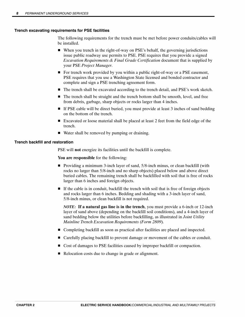
You are responsible for the following:
H Grouting around your service conduits that enter into PSE vaults (except for the vaulttypes shown in Figure 4).
H Sealing service entry conduit at PSE’s vault to prevent water from entering into yourservice panel.
H Contacting CCS for entry location approval and procedures prior to extending conduitor conduit bends into existing service vaults.
NOTE: Refer to the Customer wiring to energized PSE transformers section of thischapter for the proper procedure for entering a PSE vault.
Vault WallCustomer’s service wireconduits may enter thevault through mouseholes or knockouts inthe unshaded area.
PSE Conduit
Figure 2 Location of customer conduit in PSE vaults

PERMANENT UNDERGROUND SERVICES10
ELECTRIC SERVICE HANDBOOK/COMMERCIAL/INDUSTRIAL AND MULTIFAMILY PROJECTSCHAPTER 2
3i- 4I
2I
6CrushedRock
7i
6i
3i- 8I 2i- 8I
3i- 0I
Customer’s conduit or service cable must enterfrom beneath or through the ends of the handhole
PLAN VIEW
SIDE VIEW
Figure 3 Minimum dimensions and excavation requirements for a small,secondary connection handhole
3i- 6I 4i- 0I
SIDEVIEW
6i- 0I
6i- 0I
6ICrushedRock
2I
3i- 6IPrimary cable typically enters eitherthe front, or the front half on theside of a vault
Service and secondary cablestypically enter either the back, or the back
half on the side of a vault
PLAN VIEW
3i- 2I
No Secondary
Figure 4 Minimum dimensions and excavation requirements for a single-phasepadmount transformer vault
PERMANENT UNDERGROUND SERVICES 11
ELECTRIC SERVICE HANDBOOK/COMMERCIAL/INDUSTRIAL AND MULTIFAMILY PROJECTS CHAPTER 2
4i- 8I
SIDE VIEW
8i- 0I
4i- 4I
2I
No Secondary
PLAN VIEW
4i- 8I
3i- 6I
6I
6ICrushedRock
8i- 0I
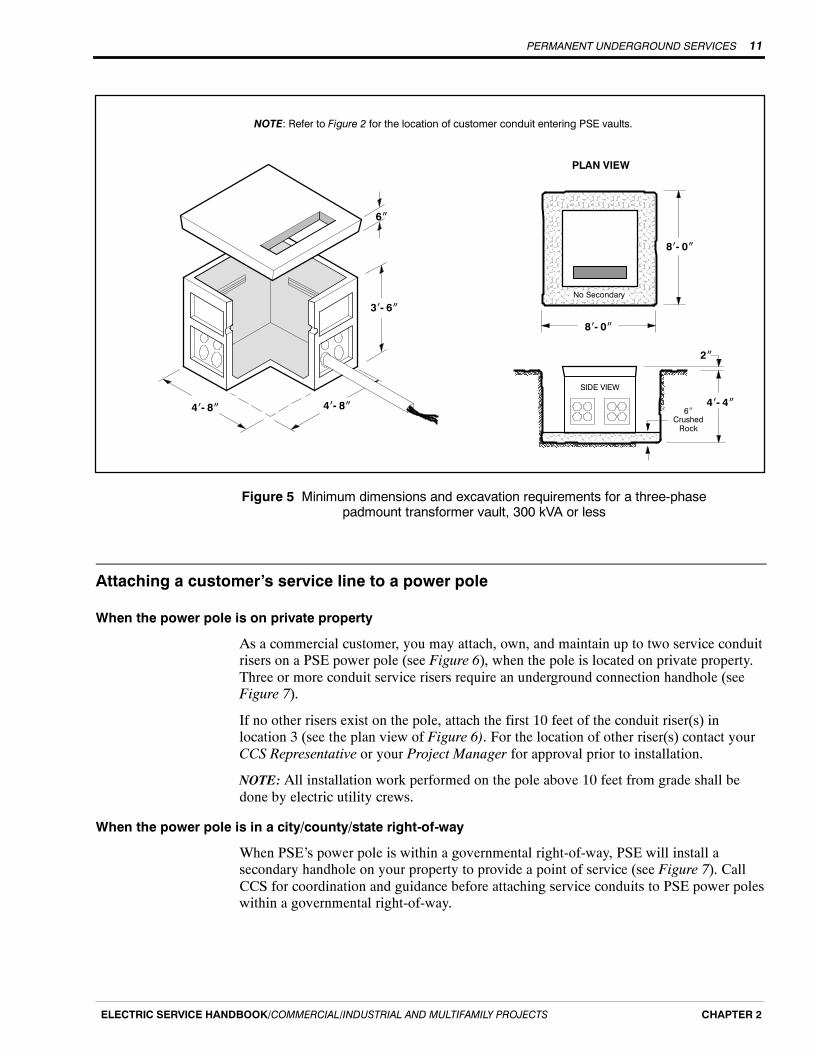
NOTE: Refer to Figure 2 for the location of customer conduit entering PSE vaults.
Figure 5 Minimum dimensions and excavation requirements for a three-phasepadmount transformer vault, 300 kVA or less
Attaching a customer’s service line to a power pole
When the power pole is on private property
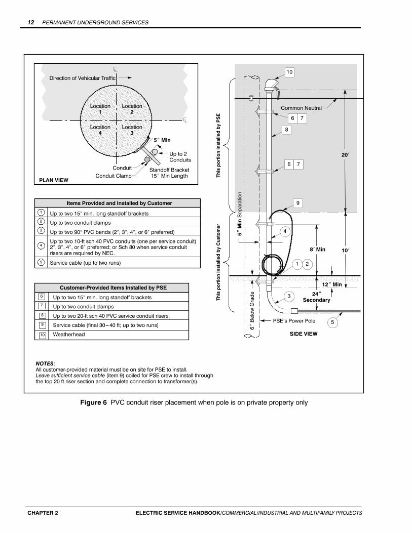
As a commercial customer, you may attach, own, and maintain up to two service conduitrisers on a PSE power pole (see Figure 6), when the pole is located on private property.Three or more conduit service risers require an underground connection handhole (seeFigure 7).
If no other risers exist on the pole, attach the first 10 feet of the conduit riser(s) inlocation 3 (see the plan view of Figure 6). For the location of other riser(s) contact yourCCS Representative or your Project Manager for approval prior to installation.
NOTE: All installation work performed on the pole above 10 feet from grade shall bedone by electric utility crews.
When the power pole is in a city/county/state right-of-way
When PSE’s power pole is within a governmental right-of-way, PSE will install asecondary handhole on your property to provide a point of service (see Figure 7). CallCCS for coordination and guidance before attaching service conduits to PSE power poleswithin a governmental right-of-way.
PERMANENT UNDERGROUND SERVICES12
ELECTRIC SERVICE HANDBOOK/COMMERCIAL/INDUSTRIAL AND MULTIFAMILY PROJECTSCHAPTER 2
Standoff Bracket15I Min Length
5IMin
Conduit
Direction of Vehicular Traffic
Conduit Clamp
Up to 2Conduits
7
6
Customer-Provided Items Installed by PSE
Up to two 15 min. long standoff brackets
Up to two conduit clamps
Up to two 90 PVC bends (2, 3, 4, or 6 preferred)
Up to two 10-ft sch 40 PVC conduits (one per service conduit)2, 3, 4, or 6 preferred; or Sch 80 when service conduitrisers are required by NEC.
Service cable (up to two runs)
Items Provided and Installed by Customer
5
1
2
3
4
Up to two 15 min. long standoff brackets
Up to two conduit clamps
Up to two 20-ft sch 40 PVC service conduit risers.
Service cable (final 30---40 ft; up to two runs)
Weatherhead
8
9
10 SIDE VIEW
NOTES:All customer-provided material must be on site for PSE to install.Leave sufficient service cable (item 9) coiled for PSE crew to install throughthe top 20 ft riser section and complete connection to transformer(s).
24ISecondary
20i
Common Neutral
5IMinSeparation
6IBelowGrade
12IMin
4
10i8iMin
ThisportioninstalledbyPSE
5
1 2
3ThisportioninstalledbyCustomer
8
9
6 7
10
6 7
PSE’s Power Pole
Location1
Location2
Location4
Location3
PLAN VIEW
Figure 6 PVC conduit riser placement when pole is on private property only

PERMANENT UNDERGROUND SERVICES 13
ELECTRIC SERVICE HANDBOOK/COMMERCIAL/INDUSTRIAL AND MULTIFAMILY PROJECTS CHAPTER 2
Secondary HandholePSE-Installed
PL
Consult PSE for number of runsallowed in secondary handhole.Customer-Installed
Final Grade
Secondary Riser, Conduit, andService Run to Secondary Handhole
PSE-Installed(Customer is still responsible for trenching)
Figure 7 PSE-installed underground connection handhole
Racking of cable in vaults
The following applies to 7 x 7 x 6-foot vaults for three-phase padmount transformers of500 kVA and greater, where 12 or more runs of 500 kcmil or larger cables are installed.
Cable ladder
In all 7 x 7 x 6-foot vaults, PSE will install a 30-inch x 4-foot ladder with 6-inch spacingbetween rungs. The cable ladder will be positioned approximately 19-inches from the leftside of the vault wall under the cable access hole.
Cable supports
Cable support racks and arms, that hold cables along the perimeter of the vault wall, arerecommended but not required by PSE.
If cable supports are installed, they shall extend a maximum of 2 feet from the vault wall.The customer may install as many cable supports as they consider necessary.
Cable training and identification
The requirements for cable training and identification are shown below.
H The cable shall extend a minimum of 7 feet above the transformer pad.
H All cables shall be bundled together by phase.
H Cables shall be zip tied to the cable ladder rungs.
H The neutral conductor shall be positioned on the cable ladder (see Figure 9).
H The cable shall be marked with colored tape to indicate its phase.

PERMANENT UNDERGROUND SERVICES14
ELECTRIC SERVICE HANDBOOK/COMMERCIAL/INDUSTRIAL AND MULTIFAMILY PROJECTSCHAPTER 2
8i-0Ior 10i-0I
11i- 0I
4i- 6I
2I
11i- 0I8I
4i- 2I
6ICrushedRock
No Secondary
PLAN VIEW
SIDE VIEW7i- 0I7i- 0I
3i- 6I
8i- 0I
Figure 8 Minimum dimensions and excavation requirements for a three-phasepadmount transformer vault, 500 kVA and larger
11i- 0I
6i- 6I
2I
11i- 0I
6ICrushedRock
PrimaryConduit(PSE)
No Secondary
PLAN VIEW
SIDE VIEW
8i-0Ior 10i-0I
8I
6i- 2I
7i- 0I7i- 0I
5i- 6I
8i- 0I
NeutralConductorPhase
Conductors
Figure 9 Racking of cable in vaults
PERMANENT UNDERGROUND SERVICES 15
ELECTRIC SERVICE HANDBOOK/COMMERCIAL/INDUSTRIAL AND MULTIFAMILY PROJECTS CHAPTER 2
Customer wiring to energized PSE transformers
Before installing commercial service underground cable into any energized transformer,coordinate the work with PSE to ensure a safe installation.
Single-phase minipad transformers
Your electrician may insert conduit 2 inches into an energized minipad transformerhandhole’s wire access holes (located at its base), without a PSE journeyman’s on-siteassistance.
For single-phase padmount transformer vaults with unistrut construction, you may, atyour discretion, provide a minimum 24-inch radius PVC bend for PSE to attach to theunistrut.
Work that involves inserting or pulling cable into the minipad handhole shall be doneonly:
H After the transformer has been de-energized.
H With the on-site assistance of a PSE journeyman.
To train the cable and mark the runs:
H Mark the cables and group them together.
H Label the conductors with the location and service address.
H Leave no more than 8 feet of cable coiled in the vault, neatly installed andtaped together.
Three-phase padmount transformers
The customer’s electrician may install and grout conduit into a vault wall or insert/pullcable into three-phase transformer vaults only:
H After the transformer has been de-energized.
H With the on-site assistance of a PSE journeyman.
To train the cable and mark the runs:
H Label each cable’s phase and the neutrals.
H Leave no more than 15 feet of cable coiled in the vault.

PERMANENT UNDERGROUND SERVICES16
ELECTRIC SERVICE HANDBOOK/COMMERCIAL/INDUSTRIAL AND MULTIFAMILY PROJECTSCHAPTER 2
Transformer locations
PSE will install padmount transformers using the clearances listed in Table 4 and shownin Figures 10 and 11.
Clearances between padmount transformers and structures must be measured from themetal portion of the transformer closest to the building or structure, including anybuilding overhangs, within the following clearances:
Table 4 Clearances for padmount transformers
Feature Clearance distance
Combustible walls or roof (including stucco) 10 feet (3 ft from acombustible wall if using areduced-flammability
transformer). See Figure 10.
Noncombustible walls (including brick, concrete, steel, and stone),provided the side of the transformer facing the wall does not havedoors. Materials that pass UBC Standard 2-1 or ASTM E136-79are considered to be noncombustible.
3 feet. See Figure 10.
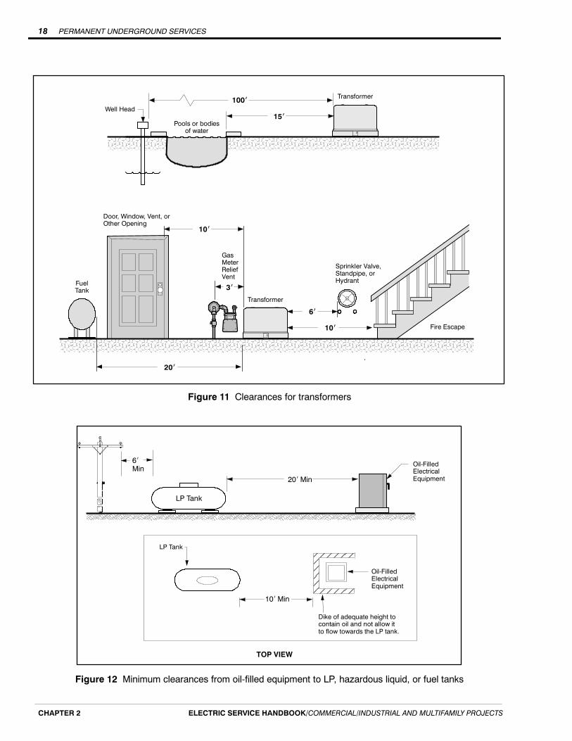
Fire sprinkler valves, standpipes, and fire hydrants 6 feet. See Figure 11.
Doors, windows, vents, fire escapes, and other building openings 10 feet. See Figure 11.
The water’s edge of a swimming pool or any body of water 15 feet. See Figure 11.
Individual domestic and irrigation wells 100 feet. See Figure 11.
Facilities used to dispense or store LP, hazardous liquids or fuels 20 feet. See Figure 12.10 feet. See Figure 12.
Gas service meter relief vents 3 feet. See Figure 11.

PERMANENT UNDERGROUND SERVICES 17
ELECTRIC SERVICE HANDBOOK/COMMERCIAL/INDUSTRIAL AND MULTIFAMILY PROJECTS CHAPTER 2
REDUCED FLAMMABILITY TRANSFORMERCLEARANCES FROM COMBUSTIBLE SURFACES
TRANSFORMER CLEARANCES FROMNONCOMBUSTIBLE SURFACES
TRANSFORMER CLEARANCES FROM NONCOMBUSTIBLEWALLS WITH COMBUSTIBLE ROOFING
10i
10i
10i
Combustiblebuildingwallsandroof.
ApprovedTransformerArea
TRANSFORMER CLEARANCES FROMCOMBUSTIBLE SURFACES
3i
3i
Combustiblebuildingwallsandroof.
10iApprovedTransformerArea
3i
3i3i
Noncombustiblebuildingwalls
ApprovedTransformerArea
3i Noncombustiblebuildingwalls
ApprovedTransformerArea
Combustibleroof or soffit
10i
10i
Noncombustibleroof and soffit
Figure 10 Clearances for transformers from structures
PERMANENT UNDERGROUND SERVICES18
ELECTRIC SERVICE HANDBOOK/COMMERCIAL/INDUSTRIAL AND MULTIFAMILY PROJECTSCHAPTER 2
Door, Window, Vent, orOther Opening
Sprinkler Valve,Standpipe, orHydrant
6i
10i
10i
Transformer
Fire Escape
3iFuelTank
GasMeterReliefVent
20i
100iWell Head
Pools or bodiesof water
15i
Transformer
Figure 11 Clearances for transformers
20i Min
LP Tank
Oil-FilledElectricalEquipment
6iMin
LP Tank
Oil-FilledElectricalEquipment
10i Min
Dike of adequate height tocontain oil and not allow itto flow towards the LP tank.
TOP VIEW
Figure 12 Minimum clearances from oil-filled equipment to LP, hazardous liquid, or fuel tanks

PERMANENT UNDERGROUND SERVICES 19
ELECTRIC SERVICE HANDBOOK/COMMERCIAL/INDUSTRIAL AND MULTIFAMILY PROJECTS CHAPTER 2
Landscaping and other obstacles
Landscaping and other obstructions shall not encroach on the clearances shown inFigures 13 and 14.
Working space
A clear and level working area equal to the full width of the equipment operatingcompartments shall extend a minimum of 10 feet from the compartment opening forpadmount equipment and 6 feet in front of subsurface equipment in vaults (seeFigures 13 and 14).
A minimum of 3 feet of clear working area for subsurface equipment and 18 inches forpadmount equipment (see Figures 13 and 14) shall be provided on the sides of theelectrical equipment without operating compartments (including sides with cooling fins).
A clearance of 36 inches is required on padmounted equipment with cooling fins (seeFigure 14).
6iMin3iMin
3iMin
3iMin
Clear WorkingSpace
Clear WorkingSpace
Figure 13 Plan view of subsurface equipment clear working space
18IMin
36IMin
Cooling Fins
Vault Lid
18IMin
EquipmentAccess Door
EquipmentAccess Door
10iMin
ClearWorkingSpace
ClearWorkingSpace
Figure 14 Plan view of padmount equipment clear working space

PERMANENT UNDERGROUND SERVICES20
ELECTRIC SERVICE HANDBOOK/COMMERCIAL/INDUSTRIAL AND MULTIFAMILY PROJECTSCHAPTER 2
Guard posts for padmount and subsurface equipment
Washington Administrative Code (WAC) requires guard posts around padmountedequipment that is exposed to vehicular traffic. PSE guard post location requirements areshown in Figure 15. You are required to supply and install these guard posts or payPSE to supply and install them.
Access Door Swing
Typical 8i x 8iConcrete Pad
3iMin
5iMax
CL
CL
3iMin
5iMax
Guard Posts
TypicalTransformer
18IMin
5iMax
5iMax
4i Max
5iMax
5iMax
5iMax
5iMax
NOTE: Installation of guard posts must be completedbefore the primary cable is installed and energized.
18IMin
Figure 15 Guard post location requirements

PERMANENT UNDERGROUND SERVICES 21
ELECTRIC SERVICE HANDBOOK/COMMERCIAL/INDUSTRIAL AND MULTIFAMILY PROJECTS CHAPTER 2
Approved guard posts
The following styles of guard posts are approved for PSE transformers:
H Schedule 40 or better galvanized steel pipe filled with concrete, 6 feet x 4 inches indiameter. The concrete shall have a minimum compressive strength of 3,000 psi after28 days. The exposed section of the post shall be painted traffic yellow.
H Precast steel-reinforced concrete post, 6 feet x 9 inches in diameter. These posts areavailable from Utility Vault Company, Auburn, WA; or Hanson Inc., Tacoma, WA.The exposed portion of the post shall be painted traffic yellow.
H Set the post 30 inches deep in undisturbed soil. If soil has been disturbed, useconcrete to stabilize the post.
H Backfill the holes with concrete.
Figure 16 illustrates both styles of guard posts.
3i- 6ILengthPaintedYellow
ConcreteDome Top
6i- 0I
GALVANIZED STEEL FILLED WITH CONCRETE
1I Dia. Lift Hole
PRECAST CONCRETE
4I6I 6I
Concrete
3i- 6ILengthPaintedYellow
6i- 0I
9I6I
Concrete
6I
30I
Figure 16 Typical guard posts
PERMANENT UNDERGROUND SERVICES22
ELECTRIC SERVICE HANDBOOK/COMMERCIAL/INDUSTRIAL AND MULTIFAMILY PROJECTSCHAPTER 2
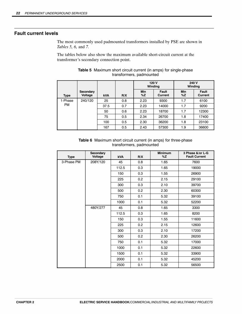
Fault current levels
The most commonly used padmounted transformers installed by PSE are shown inTables 5, 6, and 7.
The tables below also show the maximum available short-circuit current at thetransformer’s secondary connection point.
Table 5 Maximum short circuit current (in amps) for single-phasetransformers, padmounted
120 VWinding
240 VWinding
TypeSecondaryVoltage kVA R/X
Min%Z
FaultCurrent
Min%Z
FaultCurrent
1-PhasePM
240/120 25 0.8 2.23 9300 1.7 610037.5 0.7 2.23 14000 1.7 920050 0.6 2.23 18700 1.7 1230075 0.5 2.34 26700 1.8 17400100 0.5 2.30 36200 1.8 23100167 0.5 2.43 57300 1.9 36600
Table 6 Maximum short circuit current (in amps) for three-phasetransformers, padmounted
TypeSecondaryVoltage kVA R/X
Minimum%Z
3 Phase &/or L-GFault Current
3-Phase PM 208Y/120 45 0.8 1.65 7600
112.5 0.3 1.65 19000
150 0.3 1.55 26900
225 0.2 2.15 29100
300 0.3 2.10 39700
500 0.2 2.30 60300
750 0.1 5.32 39100
1000 0.1 5.32 52200
480Y/277 45 0.8 1.65 3300
112.5 0.3 1.65 8200
150 0.3 1.55 11600
225 0.2 2.15 12600
300 0.3 2.10 17200
500 0.2 2.30 26200
750 0.1 5.32 17000
1000 0.1 5.32 22600
1500 0.1 5.32 33900
2000 0.1 5.32 45200
2500 0.1 5.32 56500

PERMANENT UNDERGROUND SERVICES 23
ELECTRIC SERVICE HANDBOOK/COMMERCIAL/INDUSTRIAL AND MULTIFAMILY PROJECTS CHAPTER 2
Table 7 Maximum short circuit current (in amps) for Y-Y grounded transformers
TypeSecondaryVoltage kVA R/X
Min.%Z
3 Phase &/orL-G FaultCurrent
Three 1-phase OH & UGBanks
208Y/120 30 2.10 4,000
45 0.9 2.00 6,200
75 0.8 1.70 12,200
112.5 0.7 1.70 18,400
150 0.6 1.70 24,500
225 0.5 1.80 34,700
300 0.5 1.80 46,300
500 0.5 1.90 73,000
Three 1-phase OH & UGBanks
480Y/277 30 2.10 1,700
45 0.9 2.16 2,500
75 0.8 1.90 4,800
112.5 0.7 1.70 8,000
150 0.6 1.70 10,600
225 0.5 1.80 15,000
300 0.5 1.80 20,100
500 0.5 1.90 31,700
1000 2.20 54,600
1500 2.30 78,500

PERMANENT UNDERGROUND SERVICES24
ELECTRIC SERVICE HANDBOOK/COMMERCIAL/INDUSTRIAL AND MULTIFAMILY PROJECTSCHAPTER 2
PERMANENT OVERHEAD SERVICES 25
ELECTRIC SERVICE HANDBOOK/COMMERCIAL/INDUSTRIAL AND MULTIFAMILY PROJECTS CHAPTER 3
Chapter 3
Permanent Overhead Services
This chapter provides you with information on PSE’s permanent overhead serviceinstallation. Please follow these requirements to avoid a delay in your service hookup. Ifyou have any questions about this information, call Customer Construction Services(CCS) at 1-888-321-7779.
Service equipment installation responsibilities
Puget Sound Energy
PSE is responsible for furnishing, installing, and maintaining the primary systemequipment, overhead service wire, current transformers, meter(s), and meter wiring.
Customer
You are responsible for furnishing, installing, and maintaining all required serviceentrance equipment, including the service entrance conductors from the meterbase/socket or current transformer enclosure to PSE’s designated point of delivery. Thepoint of delivery for overhead service is at the connectors on the weatherhead.
For services where current transformers (CTs) are required, you will also need to runconduit from the CT enclosure to the meter base. Refer to Chapter 4, Section 3, CurrentTransformer (CT) Metering (up to 800 A) for more information.
Preparing for your service hookup
The following list will help you prepare your project for the installation of an overheadservice. After you complete these items, PSE will install the metering equipment andconnect your service.
1. Check for any local ordinances/covenants that may prevent you from obtaining anoverhead service.
2. Complete Electric Service Application Permanent Non-Residential 201E (Form 1378)or Electric Service Multi-Family Development 400E (Form 4409). All forms can bedownloaded at PSE.com.
3. Supply site drawings and load information to your CCS Representative (refer toChapter 1, Submitting an Application for Service).
4. Contact CCS to determine where your overhead service will originate.
5. Determine an approved meter location (refer to Chapter 4, Section 1, GeneralMetering Requirements, Meter locations).
Continued on next page
PERMANENT OVERHEAD SERVICES26
ELECTRIC SERVICE HANDBOOK/COMMERCIAL/INDUSTRIAL AND MULTIFAMILY PROJECTSCHAPTER 3
6. Verify that the service mast height requirements have been met.
7. Provide and maintain a path, clear of obstructions, between PSE’s pole and yourservice mast.
8. Provide payment for any preconstruction costs determined by your CCSRepresentative.
9. Install the required service equipment.
10. Provide and install service entrance conductors (leave a minimum of 18 inchesexposed at the weatherhead).
11. Connect the meter bases/sockets and permanently label them to indicate the part ofthe premises they serve, such as unit number.
12. Obtain an approved electrical inspection.
13. Call CCS at 1-888-321-7779 to initiate connection and energize your new service.
Service mast requirements
All requirements for the installation of the service mast are located in the NationalElectric Code (NEC) and the Washington Administrative Code (WAC) 296-46B. Thefollowing are PSE-specific requirements.
Height requirements
PSE can assist you with determining the proper service mast height. Call CCS at1-888-321-7779 for assistance.
Clearances from gas meters
A minimum horizontal clearance of 3 feet is required between electric service equipmentand the natural gas meter pressure relief vent.
Additional mast supports
Additional mast supports, typically a guy or a brace, are required for any service lineover 100 feet in length.
Screw-in service knobs
For new or altered overhead service lines, you must provide a substantial point ofattachment that meets NEC requirements.
Older screw-in type service knobs attached to the home’s wall are often inadequate tosupport modern triplexed service lines. PSE may prohibit use of service knobs if deemedinadequate.

PERMANENT OVERHEAD SERVICES 27
ELECTRIC SERVICE HANDBOOK/COMMERCIAL/INDUSTRIAL AND MULTIFAMILY PROJECTS CHAPTER 3
Installing the service equipment
List of customer-provided service entrance equipment
You are responsible for installing the following:
H Meter base/socket
H Current transformer (CT) enclosure and conduit between the meter base/socket, ifrequired
H Service mast
H Insulated clevis for service attachment
H Service entrance conductor
H Ground rods
NOTE: PSE will install the service line and meter, as well as CTs and meter wiring ifthey are required.
Terrain considerations for meter base/socket locations
Meter base/socket locations are covered in Chapter 4, Section 1 of this handbook.However, consider the type of terrain the electrical service line will cross when choosinga meter location. PSE strongly suggests avoiding service line routes that cross adriveway. Service lines crossing driveways can be hit by vehicles, causing damage to theservice equipment or structure.
Contact CCS at 1-888-321-7779 for the minimum height clearance requirements ofoverhead service wires.
If the service line will pass through any trees, you are required to prune those trees toprovide a clear path for the service line. You are also responsible for regular treepruning, and if necessary, tree removal to keep the path clear.
Customer-owned meter pole
Meter pole requirements
If a meter pole is required for the project, it is your responsibility to purchase and installit. The meter pole must meet the following requirements:
H Be sound, round, and made out of wood
H Fully pressure treated
H Class 6 or better
H 30 feet long minimum (25 feet with prior approval)
H Minimum diameter of 5-1/2 inches at the top
H Butt gain cut 12 feet from the bottom of the pole
NOTE:Multiple meter installations shall be approved by PSE’s Meter Department.
Meter pole locationsMeter poles must be:
H Accessible for reading and testing the meter
H Installed within 30 feet of the commercial building (typically)
PERMANENT OVERHEAD SERVICES28
ELECTRIC SERVICE HANDBOOK/COMMERCIAL/INDUSTRIAL AND MULTIFAMILY PROJECTSCHAPTER 3
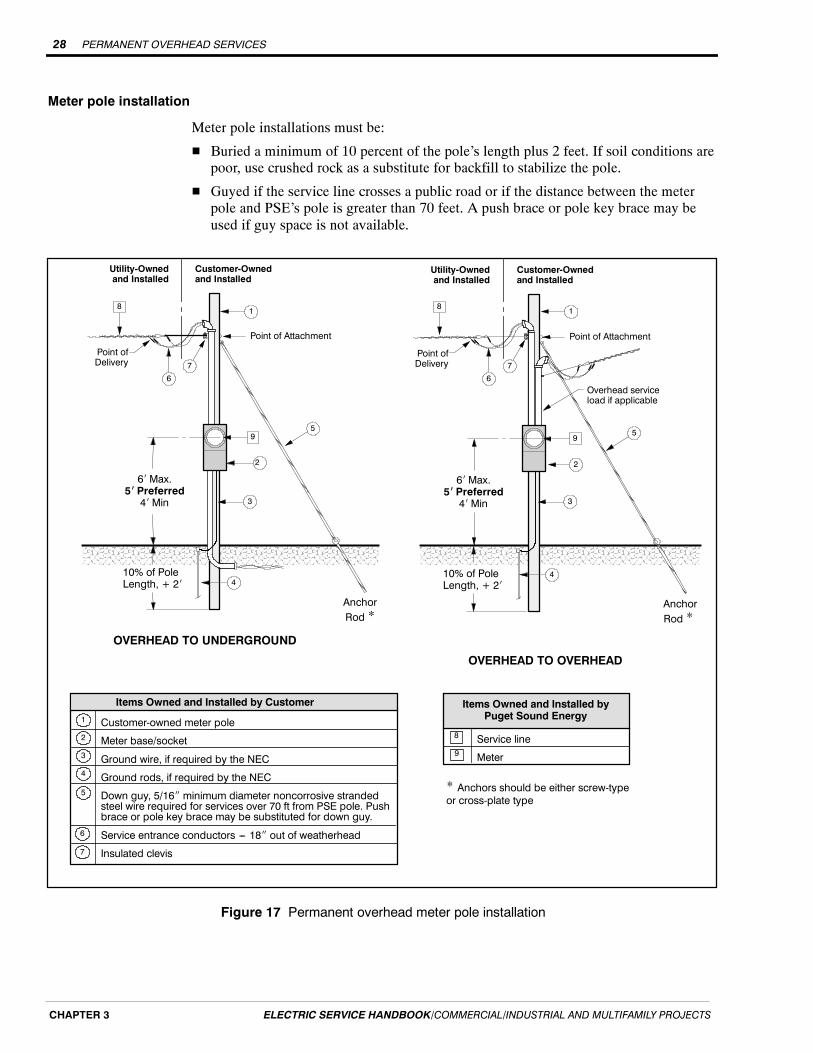
Meter pole installation
Meter pole installations must be:
H Buried a minimum of 10 percent of the pole’s length plus 2 feet. If soil conditions arepoor, use crushed rock as a substitute for backfill to stabilize the pole.
H Guyed if the service line crosses a public road or if the distance between the meterpole and PSE’s pole is greater than 70 feet. A push brace or pole key brace may beused if guy space is not available.
6i Max.5i Preferred4i Min
AnchorRod *
Utility-Ownedand Installed
Customer-Ownedand Installed
Point of Attachment
OVERHEAD TO UNDERGROUND
1
Point ofDelivery
9
8
Items Owned and Installed byPuget Sound Energy
Customer-owned meter pole
Meter base/socket
Ground wire, if required by the NEC
Ground rods, if required by the NEC
Down guy, 5/16I minimum diameter noncorrosive strandedsteel wire required for services over 70 ft from PSE pole. Pushbrace or pole key brace may be substituted for down guy.
Service entrance conductors --- 18I out of weatherhead
Insulated clevis
Items Owned and Installed by Customer
6
5
7
1
2
3
4
Service line
Meter
AnchorRod *
Utility-Ownedand Installed
Customer-Ownedand Installed
Point of Attachment
Point ofDelivery
Overhead serviceload if applicable
10% of PoleLength, + 2i
OVERHEAD TO OVERHEAD
6i Max.5i Preferred4i Min
10% of PoleLength, + 2i
8
9
4
6
7
2
3
95
4
3
2
5
18
6
7
* Anchors should be either screw-typeor cross-plate type
Figure 17 Permanent overhead meter pole installation
METER INSTALLATION 29
ELECTRIC SERVICE HANDBOOK/COMMERCIAL/INDUSTRIAL AND MULTIFAMILY PROJECTS CHAPTER 4
Chapter 4
Meter Installation
This chapter provides you with information on PSE’s metering requirements. Pleasefollow these requirements to avoid a delay in your service hookup. If you have anyquestions about this information, call Customer Construction Services (CCS) at1-888-321-7779.
NOTE: Services of 400 A or greater require the approval of PSE’s Meter Department.PSE’s Project Manager will coordinate this process.
This chapter is divided into three sections:
Section 1: General Metering RequirementsMeter installations requirements such as meter location, clearances, and multiplemeter installations.
Section 2: Self-Contained Metering RequirementsFor single-phase service 400 A or less, and three-phase services 200 A or less.
Section 3: Current Transformer (CT) Metering Requirements (up to 800 A)For services up to 800 A and switchboard metering for services over 800 A.
Other contactsIf you have Net Metering or cogeneration questions please call 425-462-3459.
Section 1: General Metering Requirements
Metering equipment responsibilities
Puget Sound EnergyPSE will furnish, install, and maintain the following equipment:H Revenue meters
H Current transformers (CT)H CT meter wiring
H The connectors where your service line interconnects with PSE’s equipment.
CustomerYou will be responsible for furnishing, installing, and maintaining the followingequipment (located beyond the point of delivery):H Meter bases/socketsH All necessary wiring and connections (except CT meter wiring)H Switches
H EnclosuresH Conduit
H Protection equipment
METER INSTALLATION30
ELECTRIC SERVICE HANDBOOK/COMMERCIAL/INDUSTRIAL AND MULTIFAMILY PROJECTSCHAPTER 4
Other customer responsibilities
Installing or removing meters by a qualified electrician
Only authorized and qualified PSE personnel shall cut seals and remove or install meters.
However, under emergency conditions, exceptions may be granted to qualifiedelectricians by contacting Customer Service at 1-888-225-5773.
When this occurs, the qualified electrician shall accept all liability for damage oralteration to equipment, injury to persons or property, and loss of revenue to PSE fromthe time the seal is removed until 72 hours after PSE has been notified that theequipment is ready to be resealed. The customer or contractor shall promptly notify PSEwhen repairs or modifications are complete.
WARNING: Use extreme caution when removing and installing meters. Depending upon thetype of service or meter base, removal of the meter does not necessarily de-energize service.
Inspections and approvals
Before a new service is energized, the installation shall be inspected and approved by thegoverning city or state electrical inspector.
Sealing provisions on enclosures
CT enclosures, switchgear, gutters that contain unmetered conductors, and meteringequipment shall have provisions for sealing.
Service conductors
Metered circuits shall not enter raceways or enclosures containing unmetered circuits,except for meter loops on poles.
All conductors shall be securely fastened in their terminals. Aluminum conductorconnections require corrosion inhibitor (electrical joint compound).
Grounding
All meter bases/sockets, enclosures, and conduit shall be bonded and grounded inaccordance with Articles 230 and 250 of the latest edition of the NEC.
When self-contained meter bases/sockets are used, the neutral conductor shall beconnected to the neutral terminal in the socket.
Customer equipment
The customer’s load monitoring equipment shall be installed only on the load side ofPSE’s metering. No customer equipment shall be allowed inside a meter or currenttransformer enclosure. This includes customer load monitoring and control devices.
NOTE: Meter base/socket and current transformer enclosures shall not be used as ajunction box.
Current-limiting fuses
Current-limiting fuses to protect the customer’s electrical system from high fault currentshall not be installed in meter bases/sockets, instrument transformer enclosures, or PSE’sdistribution transformers. They may be installed in the customer’s service panel or in aseparate enclosure between the socket and the panel. The separate enclosure may be onthe supply side of the meter bases/sockets in multiple meter installations if the enclosurehas sealing provisions.
METER INSTALLATION 31
ELECTRIC SERVICE HANDBOOK/COMMERCIAL/INDUSTRIAL AND MULTIFAMILY PROJECTS CHAPTER 4
Meter locations
Preferred locations
You are required to provide a location to install metering equipment. The meter locationmust be free from obstruction, corrosive atmosphere, abnormal temperature or vibration,and must be convenient to PSE’s distribution system.
All meters, meter equipment, and CT enclosures shall be installed at ground-levellocations (except high-rise residential structures), that are accessible 24 hours a day,7 days a week for meter reading, maintenance, testing, and installation or removal.
The meter base/socket shall be installed outside on schools, churches, halls, or othersimilar structures which may be locked during normal business hours.
NOTE: All meter locations shall be subject to approval by PSE.
Locations to avoid
Meters shall not be installed at any of the following locations:
H Below the first level of a building.
H In commercial occupancies they do not serve.
H Any place where safety may be compromised.
H On poles owned by PSE.
H On any line pole occupied solely by the telephone company, except to serve telephonecompany equipment.
Meter location requirements for manufactured commercial structures(school portables, industrial modular office, etc.)
If you are installing an overhead service to a manufactured commercial structure, ourservice equipment can be installed on the manufactured commercial structure or on acustomer-owned meter pole.
Meter bases/sockets installed on manufactured commercial structures are required to be:
H Located on an outside wall of your structure and accessible for reading and testing.
H Installed 4 to 6 feet above finished grade with a service mast that meets NECrequirements.
H The proper type for the service (see Table 8).
Meter bases/sockets must not be installed:
H In a breezeway.
H In an area that is subject to being fenced.
METER INSTALLATION32
ELECTRIC SERVICE HANDBOOK/COMMERCIAL/INDUSTRIAL AND MULTIFAMILY PROJECTSCHAPTER 4
Electrical equipment room requirements
Meter bases/sockets may be located inside an electrical equipment room that shall beused solely for power and communication equipment.
NOTE: The electrical equipment room shall be accessible 24 hours a day, 7 days a week.Additionally, the equipment room shall be well lit and not used for storage.
You must provide the following:
H A door that leads directly to the outside, or with prior approval from the PSE MeterDepartment, directly off the lobby of the structure’s main entrance. The size of thedoor shall be a minimum of 2 feet 8 inches x 6 feet 8 inches.
H If the electrical room is inside a parking garage, the minimum clearance is 8 feet6 inches (same as ADA requirement).
H A location near the door for installation of a keybox, a key fitting the equipment roomdoor for the keybox, and a sign on the exterior of the door stating “Electrical Room.”If multiple equipment rooms are needed, each equipment room door shall have adedicated key box with key. If door locks are changed, contact CCS to coordinate theexchange of new keys.
H A 2-inch conduit, from each electrical equipment room to a NEMA 3R enclosure usedfor the automated meter reading (AMR) antenna.
-- The conduit shall have a maximum of 360 degrees in total bends and be no morethan 25 lineal feet total length.
-- If a single meter is installed within the equipment room, the total length of theconduit may be extended to 70 lineal feet.
-- Contact CCS if the conduit length is greater than 25 feet.
-- Antenna enclosure requirements are shown in Figure 18.
-- A 1/8-inch minimum pull string is to be provided in the conduit.
H A NEMA 3R antenna enclosure shall be located on the first story outside wall 8 to10 feet aboveground for buildings with one meter room.
H If the building has multiple aboveground equipment rooms (allowed in high-riseresidential only) where meters are located, a 2-inch conduit pathway connecting all ofthe equipment rooms shall be provided for the AMR antenna cable.
-- From the top level equipment room, provide a 2-inch conduit to a NEMA 3Renclosure mounted on the roof of the building.
-- Mount the enclosure above the building facade and other obstructions. Preferredlocations are adjacent to or on top of the rooftop mechanical room or withinantenna farm locations (see Figure 18).
H A 2-foot-square piece of 3/4-inch plywood shall be mounted on the wall of the meterroom for an AMR repeater. Mount the plywood 4 to 6 feet above the floor near theantenna conduit entry location into the room. Provide a dedicated 120 V receptacleadjacent to the plywood.
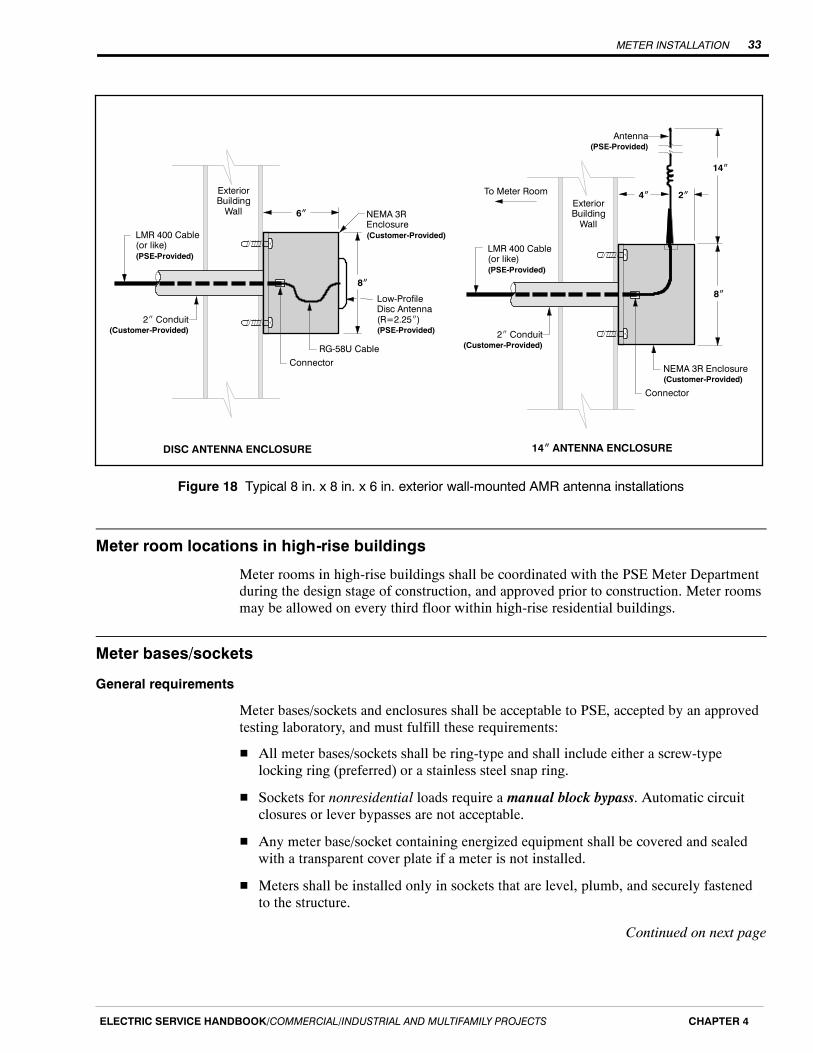
METER INSTALLATION 33
ELECTRIC SERVICE HANDBOOK/COMMERCIAL/INDUSTRIAL AND MULTIFAMILY PROJECTS CHAPTER 4
6I
Low-ProfileDisc Antenna(R=2.25I)(PSE-Provided)
Connector
ExteriorBuildingWall
RG-58U Cable
NEMA 3REnclosure(Customer-Provided)
4I
Connector
To Meter RoomExteriorBuildingWall
LMR 400 Cable(or like)(PSE-Provided)
NEMA 3R Enclosure(Customer-Provided)
2I
14I
DISC ANTENNA ENCLOSURE 14I ANTENNA ENCLOSURE
2I Conduit(Customer-Provided)
8I
LMR 400 Cable(or like)(PSE-Provided)
2I Conduit(Customer-Provided)
8I
Antenna(PSE-Provided)
Figure 18 Typical 8 in. x 8 in. x 6 in. exterior wall-mounted AMR antenna installations
Meter room locations in high-rise buildings
Meter rooms in high-rise buildings shall be coordinated with the PSE Meter Departmentduring the design stage of construction, and approved prior to construction. Meter roomsmay be allowed on every third floor within high-rise residential buildings.
Meter bases/sockets
General requirements
Meter bases/sockets and enclosures shall be acceptable to PSE, accepted by an approvedtesting laboratory, and must fulfill these requirements:
H All meter bases/sockets shall be ring-type and shall include either a screw-typelocking ring (preferred) or a stainless steel snap ring.
H Sockets for nonresidential loads require a manual block bypass. Automatic circuitclosures or lever bypasses are not acceptable.
H Any meter base/socket containing energized equipment shall be covered and sealedwith a transparent cover plate if a meter is not installed.
H Meters shall be installed only in sockets that are level, plumb, and securely fastenedto the structure.
Continued on next page

METER INSTALLATION34
ELECTRIC SERVICE HANDBOOK/COMMERCIAL/INDUSTRIAL AND MULTIFAMILY PROJECTSCHAPTER 4
H All unused openings of the meter base/socket enclosure shall be closed with plugsthat are secured tightly in place from inside the enclosures before a meter is installed.
H All meter equipment exposed to weather shall be rain-tight according to the NationalElectrical Manufacturer’s Association (NEMA) 3R minimum.
H Terminals shall be marked with a conductor range for aluminum or copperconductors. When aluminum conductors are used, the socket must be approved andclearly marked by the manufacturer for that use.
CAUTION: Strands shall not be removed to make conductors fit undersized terminals.Meter bases/sockets shall not be jumped to provide power.
Determining meter base/socket type
To determine meter base/socket types for specific voltages and amperage ratings useTable 8.
Meter base/socket clearances
NOTE: The center of the meter base/socket is always the point of reference.
For... Clearance
Base/Socket height Meter base/socket height shall be 4 ft minimum to 6 ft maximum (5 ftpreferred) above finished grade or floor (see Figure 19).
Working space H Working space in front of metering equipment (including currenttransformer enclosures) shall be at least 3 ft wide and 3 ft deep,measured from the front of the enclosure or meter face (see Figure 19).Plants, shrubs, and trees shall not be planted in this space.
H The center of all meter base/socket enclosures shall be a minimum of10 inches from adjacent walls, ceilings, or other similar obstructions(see Figure 19).
H All service equipment, including disconnect switches, shall be aminimum of 10 inches from the meter’s center.
H Building siding shall not cover or overlap the meter base/socket.
Minimum clearance from gas meter The diagrams and the measurements provided in Gas and ElectricUnderground Service Installation Requirements (Form 3061), provided inthe back pocket of this handbook, show the required minimum distancesbetween building features and the relief vent.
Recessed meters When a meter base/socket enclosure is recessed in the building wall, aflush-type socket is required. Recessed meter bases/sockets require aclearance of 10 inches in all directions between the center of the meterand the closest portion of the wall (see Figure 20).

METER INSTALLATION 35
ELECTRIC SERVICE HANDBOOK/COMMERCIAL/INDUSTRIAL AND MULTIFAMILY PROJECTS CHAPTER 4
4i Min6i Max.5i Preferred
6I Min6i Max.
10I Min
WorkingSpace
3i Min
3i Min
Top View
Figure 19 Meter base/socket minimum clearances
10IMin
10IMin
Figure 20 Minimum clearances for recessed meters

METER INSTALLATION36
ELECTRIC SERVICE HANDBOOK/COMMERCIAL/INDUSTRIAL AND MULTIFAMILY PROJECTSCHAPTER 4
Remote metering
Normally, a meter base/socket and associated devices (current transformers, etc.) areattached to a permanent or fixed structure, such as a building, that contains the loadbeing served. If there is no permanent or fixed structure for the load, then remotemetering is allowed.
Remote metering consists of a meter on a meter pedestal, typically located within 30 feetof the load or the PSE equipment that serves the customer.
Remote metering is allowed only for:
H City, county, or state streetlights and traffic lights;
H Homeowners’ associations; and
H Railroads.
All remote metering requires PSE’s Meter Department approval before constructionbegins. Contact CCS if you require remote metering.
Meter pedestal requirements for remote metering
Meter pedestals must meet the specifications of EUSERC Section 300 (Metering andService Equipment 0 -- 600 V), and drawings 308 or 309, with the following additionalspecifications for the meter base/socket:
H The meter base/socket shall be a 200 A Form 12S with the fifth jaw in the 9 o’clockposition.
H The test bypass safety disconnect shall meet EUSERC drawings 311 or 312.
H For drawing 309, the dimension from the center of the meter base/socket to the insidetop flange should be a minimum of 10 inches.
H Enclosed metering for protection from vandalism, state or city traffic, andstreetlighting must meet EUSERC drawings 300, 308 or 309 and PSE pedestalclearance and socket requirements (10 inches minimum from the center of the meterto the inside flanges on the sides and top of the pedestal, and 10 inches minimumfrom the meter base/socket to the door).
H Drawings shall be submitted for approval by the manufacturer, noting the EUSERCand PSE drawings and specifications used.
H Meter pedestals shall be on structures such as masonry, concrete, or metal.
H Meter pedestals exposed to vehicular traffic (other than those used for trafficmanagement loads) shall be protected by guard posts as described in Chapter 3,Guard posts for padmount and subsurface equipment.
H Single-phase remote services 60 A or less can be mounted on a 6 x 6-inch fullypressure-treated wood post. The minimum height of the meter shall be 3 feet.
METER INSTALLATION 37
ELECTRIC SERVICE HANDBOOK/COMMERCIAL/INDUSTRIAL AND MULTIFAMILY PROJECTS CHAPTER 4
Meter pedestal location
The metering pedestal must be located so that the access for the metering and pullsection are free of surrounding obstructions, with at least 36 inches of working spaceclearance in front of the equipment.
Remote service requirements based on service ampacity
H Remote services 800 A or less for nonresidential loads shall be mounted onpermanent support structures that are made of galvanized steel pipe with unistrutcross-braces, concrete, or masonry blocks. Support structures made of wood (treatedor not) are unacceptable.
-- The customer shall provide a 3-foot x 3-foot x 3-inch thick concrete padsurrounding the meter or holes 2-feet-deep that are filled with concrete to anchorthe structure.
-- The minimum height of the meter shall be 3 feet.
-- Meter base/sockets shall be permanently labeled to indicate the address they serve.PSE requires engraved phenolic nameplates or adhesive die-cut labels at least1-inch high. Service will not be established until marking is complete
NOTE: Felt-tip pens and label maker tape are not considered permanent marking.
Other requirements specified in this handbook for meter bases/sockets and CTenclosures apply.
H Remote services greater than 800 A -- Remote services 800 A or greater requireEUSERC outdoor switchgear. Ask your CCS Representative for more information.

METER INSTALLATION38
ELECTRIC SERVICE HANDBOOK/COMMERCIAL/INDUSTRIAL AND MULTIFAMILY PROJECTSCHAPTER 4
Multiple meter installations
MultifamilyOn residential multimeter panels, the minimum spacing between socket centers shall be7-1/2 inches horizontally, 8-1/2 inches vertically, and the center line shall be a minimumof 3 feet and a maximum of 6 feet above the floor or finished grade.
Multimeter installations serving residential living units shall comply with the equipmentarrangement requirements are shown in Figure 21.
Meter base/socket jumpers shall not be used to serve house meters. House meters shallbe served in the following ways:
H A dedicated set of service entrance conductors.
H A tap on the bussing of residential multimeter panels.
H All-in-one factory assembled multimeter panels.
NOTE: PSE requires house meters to have manual block bypasses.
8-1/2IMin
ServiceEntrance
MainDisconnect
7-1/2IMin
Apt 1 Apt 2 Apt 3
Apt 11 Apt 12 Apt 13
Apt 21 Apt 22 Apt 23
Note: House meter bases/socketsrequire a manual block bypass.
10IMin
4i Min5i Preferred6i Max.
Floor or Finished Grade
6iMax.
3iMin
ResidentialMeters
Nonresidential Meters
ServiceEntrance
PSE SecondaryHandhole
or Transformer Vault Typically located nearthe property line
Figure 21 Typical factory-built residential multimeter panel for multifamily complex

METER INSTALLATION 39
ELECTRIC SERVICE HANDBOOK/COMMERCIAL/INDUSTRIAL AND MULTIFAMILY PROJECTS CHAPTER 4
Nonresidential
On nonresidential multiple meter panels, the minimum spacing between socket centersshall be 12 inches horizontally, 12 inches vertically, and the meter shall be a minimum of3 feet and a maximum of 6 feet above the floor or finished grade.
Meters shall be adequately protected from mechanical damage. Factory-built multiplemeter equipment shall be approved by the PSE Meter Department. A typical example ofa nonresidential multiple meter installation is shown in Figure 22.
Service Entrances
Load
12IMin
Clearances in this drawing (nonresidential) also apply for factory-built multiple meter panels,except that meters may be a minimum of 3 feet above floor.Meter bases/sockets require a manual block bypass.More than six meters requires a main disconnect per NEC.277/480 V services shall have a service disconnect ahead of each meter and a safety socket.
Notes:
232 NE 10St. 234 NE 10St. 236 NE 10St. 238 NE 10StSuite A
238 NE 10St.Suite B
4i Min5i Preferred6i Max.
12IMin
Floor or Finished Grade
Figure 22 Typical multiple nonresidential meter installations for services 200 A or less
Multiple meter base/socket labeling
Meter bases/sockets shall be permanently labeled to indicate the part of the premises theyserve (i.e., unit number). PSE requires engraved phenolic nameplates or adhesive die-cutlabels at least 1-inch high. Service will not be established until marking is complete.
NOTE: Felt-tip pens and label maker tape are not considered permanent marking.
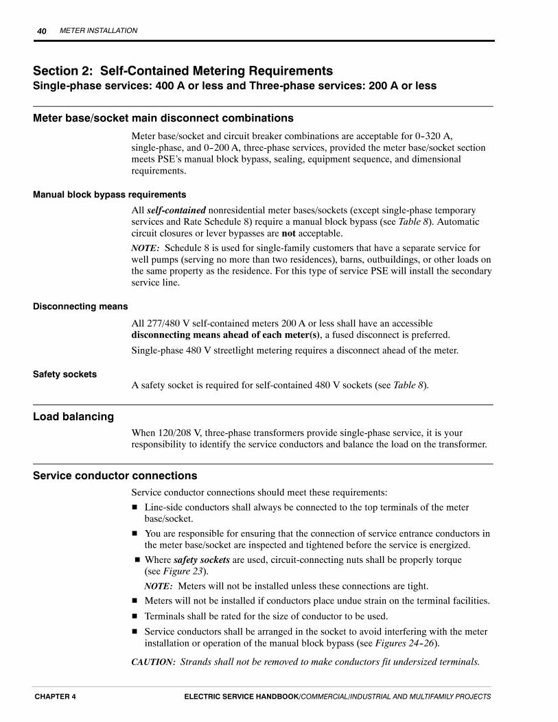
METER INSTALLATION40
ELECTRIC SERVICE HANDBOOK/COMMERCIAL/INDUSTRIAL AND MULTIFAMILY PROJECTSCHAPTER 4
Section 2: Self-Contained Metering RequirementsSingle-phase services: 400 A or less and Three-phase services: 200 A or less
Meter base/socket main disconnect combinations
Meter base/socket and circuit breaker combinations are acceptable for 0--320 A,single-phase, and 0--200 A, three-phase services, provided the meter base/socket sectionmeets PSE’s manual block bypass, sealing, equipment sequence, and dimensionalrequirements.
Manual block bypass requirements
All self-contained nonresidential meter bases/sockets (except single-phase temporaryservices and Rate Schedule 8) require a manual block bypass (see Table 8). Automaticcircuit closures or lever bypasses are not acceptable.
NOTE: Schedule 8 is used for single-family customers that have a separate service forwell pumps (serving no more than two residences), barns, outbuildings, or other loads onthe same property as the residence. For this type of service PSE will install the secondaryservice line.
Disconnecting means
All 277/480 V self-contained meters 200 A or less shall have an accessibledisconnecting means ahead of each meter(s), a fused disconnect is preferred.
Single-phase 480 V streetlight metering requires a disconnect ahead of the meter.
Safety socketsA safety socket is required for self-contained 480 V sockets (see Table 8).
Load balancingWhen 120/208 V, three-phase transformers provide single-phase service, it is yourresponsibility to identify the service conductors and balance the load on the transformer.
Service conductor connectionsService conductor connections should meet these requirements:
H Line-side conductors shall always be connected to the top terminals of the meterbase/socket.
H You are responsible for ensuring that the connection of service entrance conductors inthe meter base/socket are inspected and tightened before the service is energized.
H Where safety sockets are used, circuit-connecting nuts shall be properly torque(see Figure 23).
NOTE: Meters will not be installed unless these connections are tight.
H Meters will not be installed if conductors place undue strain on the terminal facilities.
H Terminals shall be rated for the size of conductor to be used.
H Service conductors shall be arranged in the socket to avoid interfering with the meterinstallation or operation of the manual block bypass (see Figures 24--26).
CAUTION: Strands shall not be removed to make conductors fit undersized terminals.
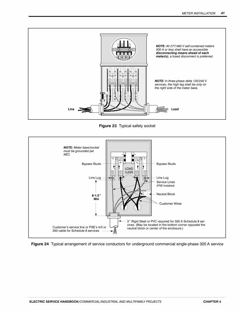
METER INSTALLATION 41
ELECTRIC SERVICE HANDBOOK/COMMERCIAL/INDUSTRIAL AND MULTIFAMILY PROJECTS CHAPTER 4
LoadLine
NOTE: In three-phase delta 120/240 Vservices, the high leg shall be only onthe right side of the meter base.
NOTE: All 277/480 V self-contained meters200 A or less shall have an accessibledisconnecting means ahead of eachmeter(s), a fused disconnect is preferred.
Figure 23 Typical safety socket
8-1/2IMin
NOTE: Meter base/socketmust be grounded perNEC.
Bypass Studs
3I Rigid Steel or PVC required for 320 A Schedule 8 ser-vices. (May be located in the bottom corner opposite theneutral block or center of the enclosure.)
Customer Wires
Line LugService Lines(PSE-Installed)
Line Lug
Bypass StudsLOADLUGS
Neutral Block
Customer’s service line or PSE’s 4/0 or350 cable for Schedule 8 services
Figure 24 Typical arrangement of service conductors for underground commercial single-phase 320 A service

METER INSTALLATION42
ELECTRIC SERVICE HANDBOOK/COMMERCIAL/INDUSTRIAL AND MULTIFAMILY PROJECTSCHAPTER 4
NOTE: Meter base/socket must begrounded per NEC.
Service EntranceConductors(Customer-Installed)
Customer Wires
Bypass Studs
Line Lug Line LugBypass Studs
Load Lug
NOTE: Line lugs shall be turned180_ to allow proper insertion ofwire and to keep from blockingbypass area.
Neutral Block
Load Lug
Figure 25 Typical arrangement of service conductors for overhead commercial single-phase 320 A service
Bypass Block
Service EntranceConductors(Customer-Installed)
Customer Wires
Load
NOTE: In three-phase delta 120/240 Vservices, the high leg shall be only on theright side of the meter base.
NOTE: Service wires shall be installedbehind bypass block so operation ofbypass is not restricted.
Figure 26 Typical arrangement of service conductors for 120/208 V three-phase self-contained 200 A service
METER INSTALLATION 43
ELECTRIC SERVICE HANDBOOK/COMMERCIAL/INDUSTRIAL AND MULTIFAMILY PROJECTS CHAPTER 4
Self-contained meter base/socket requirements
Single-phase services: 400 A or less
A manual block bypass is required on all commercial services. Automatic circuitclosures, sliders, and lever bypasses are not acceptable.
Single-phase services: 200 A or less
A self-contained meter base/socket shall be installed on all new and remodeledsingle-phase services (120/240 V or 120/208 V), where the current-carrying capacity ofthe service entrance conductors does not exceed 200 A, as specified in NEC (see Table 8,Meter Base/Socket Configuration A).
Single-phase services: 201 to 400 A
Two options are available:
1. A self-contained 320-A meter base/socket with a manual block bypass is requiredon all new and remodeled single-phase services (120/240 V) over 200 A, wherethe current-carrying capacity of the service entrance conductors does not exceed400 A, as specified in the NEC (see Table 8, Meter Base/Socket Configuration A).
2. Current transformer metering is available at additional cost; contact PSE’s CCSoffice (see Table 8, Meter Base/Socket Configuration B).
Single-phase services: 120/208 V, 200 A or less
A 5-terminal meter safety socket shall be installed where the fifth terminal is placed inthe nine o’clock position connected to the socket neutral bus conductor (see Table 8,Meter Base/Socket Configuration C).
Single-phase streetlight services: 120/240 V or 240/480 V pedestals
A 5-terminal meter safety socket shall be installed where the fifth terminal is placed inthe nine o’clock position connected to the socket neutral bus conductor (see Table 8,Meter Base/Socket Configuration C).
NOTE: All 240/480 V services require an accessible disconnect ahead of the meter, afused disconnect is preferred.
Three-phase services: 200 A or less
All three-phase services
A manual block bypass is required on all commercial services. Automatic circuitclosures, sliders, and lever bypasses are not acceptable.
The neutral (grounded conductor) shall be connected or tapped to the third terminal fromthe left on the lower terminals (see Table 8, Meter Base/Socket Configuration D).

METER INSTALLATION44
ELECTRIC SERVICE HANDBOOK/COMMERCIAL/INDUSTRIAL AND MULTIFAMILY PROJECTSCHAPTER 4
Three-phase services: 120/240 V, four-wire delta (Restricted — available only for existing services)
In addition to the requirements for all three-phase services, the high-leg (power leg) shallbe connected through the right-hand terminals of the socket.
Three-phase services: 277/480 V
An accessible disconnect (fused disconnect preferred) ahead of each meter base/socketand a safety socket with a manual bypass are required.
Table 8 Single-phase (nonresidential only) and all three-phase meter base/socket types
Voltage WiresServiceCapacityAmp
No. ofTerminals
MeterSocketConfig. *
ManualBlockBypassRequired?
AccessibleDisconnectAhead &
Safety SocketRequired?
Socket
SINGLE-PHASE NONRESIDENTIAL
120/240 3 up to 200 4 A Yes No Self-contained socket
120/240 3 201 to 320 4 A Yes No Self-contained 320 Asocket
120/240 3 above 320 6 B n/a n/aInstrument transformerrated with provision for testswitch
120/208 3 up to 200 5 C Yes No Preferred arrangement
120/240 3 up to 200 5 C Yes Safety socketonly
Streetlight applicationsonly
240/480 3 up to 200 5 C Yes Yes Streetlight applicationsonly
ALL THREE-PHASE
120/208 4 up to 200 7 D Yes No Self-contained socket
120/208 4 above 200 13 E n/a n/aInstrument transformerrated with provision for testswitch
120/240 4 up to 200 7 D Yes No
Self-contained socket(RESTRICTEDAPPLICATION) — High legon right terminals
120/240 4 above 200 13 E n/a n/a
Instrument transformerrated with provision for testswitch (RESTRICTEDAPPLICATION)
277/480 4 up to 200 7 D Yes
YesFused
disconnectpreferred
Self-contained safetysocket
277/480 4 above 200 13 E n/a n/aInstrument transformerrated with provision for testswitch
* Meter Base/Socket Configurations
A B C D E
METER INSTALLATION 45
ELECTRIC SERVICE HANDBOOK/COMMERCIAL/INDUSTRIAL AND MULTIFAMILY PROJECTS CHAPTER 4
Section 3: Current Transformer (CT) Metering Requirements (up to 800 A)Single-phase services: over 400 A and Three-phase services: over 200 A
Puget Sound Energy’s installation responsibilities
PSE is responsible to provide and install:
H Instrument transformers
H Meters and test switches
H Metering circuits (wiring)
Customer’s installation responsibilities
Provisions for current transformers shall be made when the current-carrying capacity ofthe service entrance conductors exceeds 400 A single-phase or 200 A three-phase, asdetermined by the NEC.
Meter base/socket
You are responsible to provide and install the meter base/socket.
Metering circuit conduit
You are responsible to provide and install the metering circuit conduit. Metallic conduit(EMT or Rigid) or Schedule 80 PVC conduit is required between the meter base/socketand CT enclosure.
H The conduit shall be sized as follows:-- Single-phase: 1 inch minimum-- Three-phase: 1-1/4 inches minimum
H Conduit shall be as short as possible and shall not exceed 50 feet in length or360 degrees in bends.
H A pull string is required in any meter conduit over 25 feet.
H When metallic conduit (EMT or Rigid) is used, grounding bushings shall be used atboth ends.
H Conduit shall run from the CT enclosure and enter the test switch portion of themeter base/socket.
NOTE: Metering circuit conduit shall not contain condulets, junction boxes, or flex conduit.The preferred method of installing conduits entering the CT enclosure is shown inFigure 27.
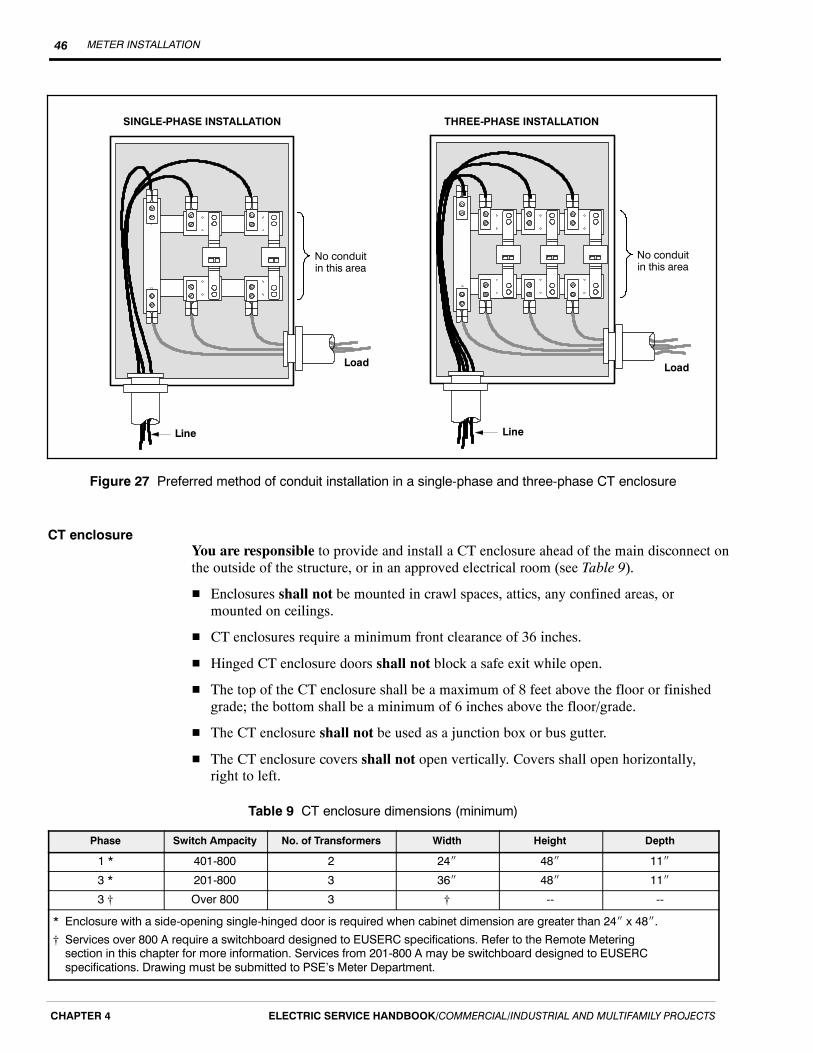
METER INSTALLATION46
ELECTRIC SERVICE HANDBOOK/COMMERCIAL/INDUSTRIAL AND MULTIFAMILY PROJECTSCHAPTER 4
Load
Line
Load
No conduitin this area
No conduitin this area
Line
THREE-PHASE INSTALLATIONSINGLE-PHASE INSTALLATION
Figure 27 Preferred method of conduit installation in a single-phase and three-phase CT enclosure
CT enclosureYou are responsible to provide and install a CT enclosure ahead of the main disconnect onthe outside of the structure, or in an approved electrical room (see Table 9).
H Enclosures shall not be mounted in crawl spaces, attics, any confined areas, ormounted on ceilings.
H CT enclosures require a minimum front clearance of 36 inches.
H Hinged CT enclosure doors shall not block a safe exit while open.
H The top of the CT enclosure shall be a maximum of 8 feet above the floor or finishedgrade; the bottom shall be a minimum of 6 inches above the floor/grade.
H The CT enclosure shall not be used as a junction box or bus gutter.
H The CT enclosure covers shall not open vertically. Covers shall open horizontally,right to left.
Table 9 CT enclosure dimensions (minimum)
Phase Switch Ampacity No. of Transformers Width Height Depth
1 * 401-800 2 24I 48I 11I
3 * 201-800 3 36I 48I 11I
3 † Over 800 3 † -- --
* Enclosure with a side-opening single-hinged door is required when cabinet dimension are greater than 24I x 48I.† Services over 800 A require a switchboard designed to EUSERC specifications. Refer to the Remote Meteringsection in this chapter for more information. Services from 201-800 A may be switchboard designed to EUSERCspecifications. Drawing must be submitted to PSE’s Meter Department.

METER INSTALLATION 47
ELECTRIC SERVICE HANDBOOK/COMMERCIAL/INDUSTRIAL AND MULTIFAMILY PROJECTS CHAPTER 4
Mounting the CT
You are responsible to do the following:
H Install a CT mounting base on services of 800 A or less (see Figures 28 and 29).
H Provide and install two bolt lugs on the line and load sides of each phase and theneutral bus.
NOTE: An instrument transformer enclosure shall contain only the main serviceconductors. A maximum of four main service conductors may be served off the load sideof each current transformer mounting bracket, as long as the lugs are not stacked and donot restrict the mounting of CTs. Use “stair-step” lugs if more than two conductors areterminated at each CT. A gutter or junction box is required if there are more than fourmain service conductors.
H All new CT brackets or rebuilt CT enclosures shall be 50 kA fault current rated.
8I Min
1-3/8I
1-3/8I
8-1/8I
Bus Marking “CT”(Typical 2 Places)
5I
1-1/2I
1-1/2I
CT Mounting Bolts(Typical 4 Places - See Note 3)
7/8I
3/4I
3/4I
1-3/4I
1-3/4I
Cable Term. Bolts(Typical 4 Places - See Note 3)
10-32 MachineScrew & Washer
Drilled andTapped into Bus
2I Min2-1/2I Max.
1/4I
3-1/2I
Insulating Support (See Note 1)
Insulating Barrier
EUSERC 328A SHOWN
N
NOTES:
1. Insulated supports shall be rated for the serving voltage and have sufficientmechanical strength for the application.
2. Mounting base accepts bar-type current transformers only.3. Two 1/2-inch steel bolts shall be provided for each cable terminating positionand each bolt shall be furnished with a spring washer and a nut. The springwasher may be either a cone-type (belleville) or a split-ring washer and a flatwasher. Bolts shall be secured in place and spaced as shown. All parts shall beplated to prevent corrosion.
Figure 28 Single-phase CT mounting base bracket. EUSERC 328A (shown) or 328B
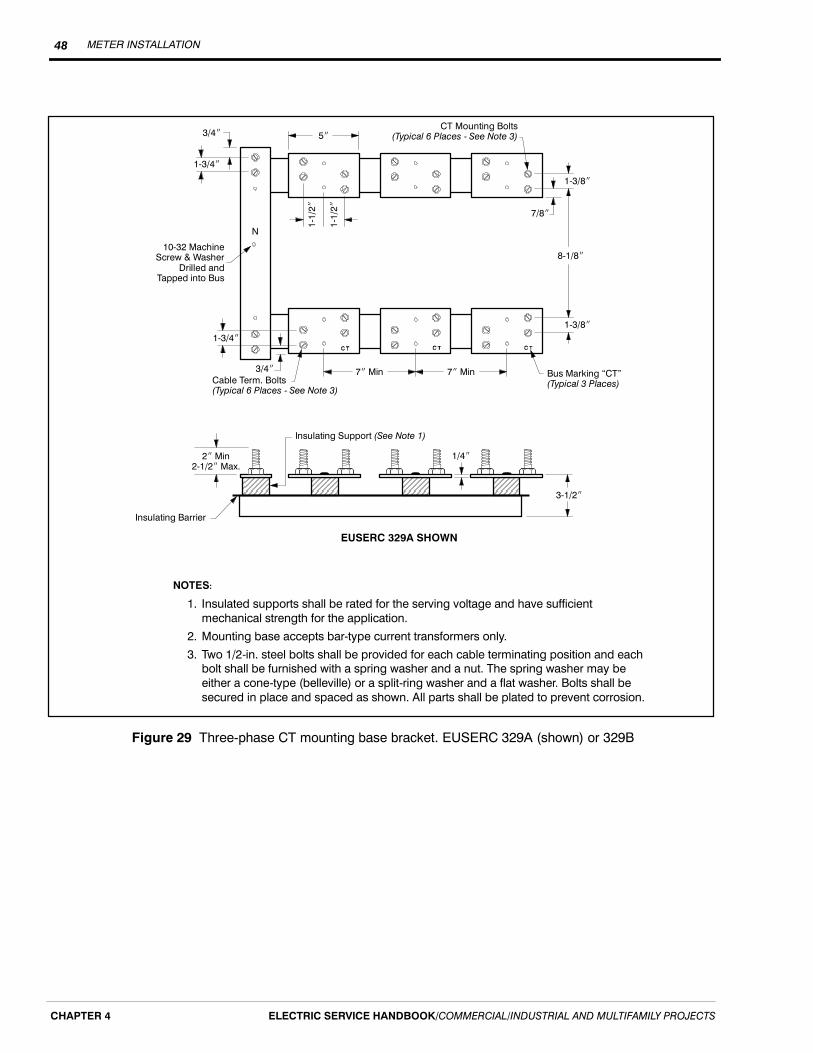
METER INSTALLATION48
ELECTRIC SERVICE HANDBOOK/COMMERCIAL/INDUSTRIAL AND MULTIFAMILY PROJECTSCHAPTER 4
7I Min Bus Marking “CT”(Typical 3 Places)
5I
1-1/2I
1-1/2I
CT Mounting Bolts(Typical 6 Places - See Note 3)3/4I
3/4I
1-3/4I
1-3/4I
Cable Term. Bolts(Typical 6 Places - See Note 3)
10-32 MachineScrew & Washer
Drilled andTapped into Bus
2I Min2-1/2I Max.
1/4I
3-1/2I
Insulating Support (See Note 1)
Insulating Barrier
7I Min
1-3/8I
1-3/8I
8-1/8I
7/8I
EUSERC 329A SHOWN
N
NOTES:
1. Insulated supports shall be rated for the serving voltage and have sufficientmechanical strength for the application.
2. Mounting base accepts bar-type current transformers only.3. Two 1/2-in. steel bolts shall be provided for each cable terminating position and eachbolt shall be furnished with a spring washer and a nut. The spring washer may beeither a cone-type (belleville) or a split-ring washer and a flat washer. Bolts shall besecured in place and spaced as shown. All parts shall be plated to prevent corrosion.
Figure 29 Three-phase CT mounting base bracket. EUSERC 329A (shown) or 329B

METER INSTALLATION 49
ELECTRIC SERVICE HANDBOOK/COMMERCIAL/INDUSTRIAL AND MULTIFAMILY PROJECTS CHAPTER 4
Customer requirements for switchboard metering (over 800 A)
A custom-built switchboard constructed to Equipment Utility Service RequirementsCommittee (EUSERC) specifications is required for services over 800 A. Switchboardmetering may be used on services from 201-800 A, at your discretion.
Approval drawings required
Approval drawings shall be submitted for all switchboard metering prior to shipmentfrom the manufacturer. One set of drawings shall be sent directly to the PSE MeterDepartment for their required approval.
Three-phase services
Three-phase services require 13-terminal meter bases/sockets mounted on theswitchboard according to EUSERC 332 (see Figure 31, Diagram B), or mountedremotely and connected with approved conduit. The conduit shall terminate in the CTcompartment and the test switch portion of the meter base/socket (see Figure 31).
EUSERC 332Configuration
13-terminal meter base/socketsurface-mounted to face ofswitchboard panel
13-terminal meter base/socketremotely-mounted
4i Min5i Preferred6i Max.
Figure 30 Options for switchboard meters
Diagram B120/208 V, 4-Wire Wye277/480 V, 4-Wire Wye120/240 V, 4-Wire DeltaAll dimensions are minimum
DIAGRAM A120/240 V SINGLE-PHASE METER BASE/SOCKET
DIAGRAM BTHREE-PHASE SINGLE METER BASE/SOCKET
20IMin
12IMin
Test SwitchSpace
4IMin
To CT CAN 111I
9I
NOTE 1– No more than four 90_ bends– 50 feet maximum length– No Condulets in the run
20IMin
12I
Test SwitchSpace
4-1/2IMin
11I
9I
To CT Can 1
1 MinConduit Dia
1- 1/4 MinConduit Dia
Figure 31 Instrument-rated CT meter bases/sockets

METER INSTALLATION50
ELECTRIC SERVICE HANDBOOK/COMMERCIAL/INDUSTRIAL AND MULTIFAMILY PROJECTSCHAPTER 4

TEMPORARY SERVICES 51
ELECTRIC SERVICE HANDBOOK/COMMERCIAL/INDUSTRIAL AND MULTIFAMILY PROJECTS CHAPTER 5
Chapter 5
Temporary Services
What this chapter contains
In this chapter you will find answers to questions such as:
H What are the installation requirements for underground and overhead service?
H What are the trenching requirements?
H How do I locate existing underground utilities before I dig?
H How do I get my temporary service energized?
Three-phase temporary service
If you require three-phase temporary service, your Project Manager will contact PSE’sMeter Department.
DefinitionA temporary (temp) service is a means of supplying electricity to your site for lessthan one year. Typically, a temp service provides power for the construction phase ofyour project, while provisions are being made for your permanent power system. Tempservice is provided underground or overhead depending on available PSE facilities.
Obtaining your temporary service from existing power facilities
The following information applies to your temp service installation:
H Determine if you need overhead or underground service (see Preface, Figure 1).
H Call PSE and establish an account with PSE and place your temp service order.
H Obtain an electrical work permit.
H Order underground utility locate service by contacting the 811 “Call Before You Dig”hotline two business days before digging.
H Prepare the job site and install your temp service equipment (service post, pedestal,and meter base).
H Obtain an electrical inspection approval of your temp service equipment (this is doneby you or your contractor).
H Call PSE to request that your temp service be connected and energized after yourelectrical inspection is complete.
H Apply for permanent service.
H At your request, we will check your site to determine if engineering is required.
If you have any questions, please call Customer Construction Services (CCS) at1-888-321-7779.

TEMPORARY SERVICES52
ELECTRIC SERVICE HANDBOOK/COMMERCIAL/INDUSTRIAL AND MULTIFAMILY PROJECTSCHAPTER 5
SchedulingMost temp services are connected to existing power facilities and engineering is notrequired. In these cases temp services are typically energized 3 to 5 days after yourinstallation has passed inspection. Depending on complexity and work volume, timeframes will vary.
Customer charge for service
Charges vary due to the type of system we have in your area. Your CCS Representativewill explain current temp service fees.
Temporary meter base/socket requirements
You are required to provide a meter socket with the following specifications:
H A ring-type socket that includes a screw-type, stainless steel, or aluminum meter ring(snap-type rings must be stainless steel).
H Rated 120/240 V
H Single-phase
H Minimum rating of 100 A
H Maximum rating of 200 A
H Four jaws
H Underwriters Laboratory (UL) approved
NOTE: A 120/208 V single-phase service requires a 5-terminal meter base with the fifthterminal tied to the neutral bus conductor. A 277/480 V three-phase service requires anaccessible disconnect ahead of each meter socket and a safety socket with a manualbypass.
If you would like a service of 201 A or greater, refer to the metering requirements inChapter 4, Meter Installation, located in this handbook.
Temporary underground services
Temp underground service is available in PSE’s service area where the existing powerfacilities are installed underground.
The process and cost of obtaining your temp underground service can vary, depending onthe location of our existing facilities. If there is a power stubout, handhole, pedestal, ortransformer located on your property (see Preface, Figure 1), engineering may not berequired. Simply install your temp service facilities (see Figure 32 and Figure 33),obtain an electrical inspection, and call PSE to connect your temp service.

TEMPORARY SERVICES 53
ELECTRIC SERVICE HANDBOOK/COMMERCIAL/INDUSTRIAL AND MULTIFAMILY PROJECTS CHAPTER 5
Meter locationTo properly locate your temp meter pedestal, set the meter pedestal on your property nomore than 5 feet from the transformer, stubout, handhole, or pedestal.
If a distance greater than 5 feet is required, please contact a CCS Representative forapproval prior to construction.
Trenching and excavation requirements
It is the customer’s responsibility to provide the trenching needed to connect to a powerstubout (shown in Figure 32). The cable you provide is to be sized according to the NECand have a minimum 24 inches of backfill coverage.
NOTE: A 4-foot-square excavation is required at the stubout to provide working room forour personnel to splice your cable to ours.
If the connection point to PSE facilities is a handhole, pedestal, or transformer; trench upto the nearest side and leave your wires exposed. If you discover any other conductorswhile digging your trench, please leave them covered. If further trenching is required, ourpersonnel will complete it.
Remember to order underground utility locate service by contacting the 811 “Call BeforeYou Dig” hotline two business days before digging.
NOTE: Any trenching within 24 inches of existing underground facilities, must be doneby hand.
26I
5iMax.
PSE StuboutStubout conduitcovering the temporaryconnection
4i
PSE Conductor
Customer Post,Meter Base,and Panel
4i
Customercable
6i Maximum5i Preferred4i Minimum
Figure 32 Trenching requirements for power stubout

TEMPORARY SERVICES54
ELECTRIC SERVICE HANDBOOK/COMMERCIAL/INDUSTRIAL AND MULTIFAMILY PROJECTSCHAPTER 5
Underground temporary service installation process
The following items must be completed before energizing your underground tempservice:
1. Contact a CCS Representative at 1-888-321-7779, and request your tempunderground service.
2. Obtain an electrical work permit from the inspecting agency.
3. Order underground utility locate service by contacting the 811 “Call Before YouDig” hotline two business days before digging.
4. Install your meter pedestal and meter base/socket in the appropriate location (seeFigures 32 and 33).
5. Provide the appropriately sized conductor from your meter socket to PSE’sconnection point. Please leave 5 feet of extra cable at the stubout or handhole,and 10 extra feet at a transformer. Consult the NEC for the appropriate cablesizes.
6. Obtain and pass an electrical inspection.
7. Trench up to and expose the PSE connection point at the stubout, handhole, ortransformer.
8. If trenching is provided, cover your cable except in the work pit where ourpersonnel will be splicing your cable to ours.
9. After the above items are complete, call CCS at 1-888-321-7779 and inform aCCS Representative that your installation has been inspected and that you areready for your temp service.
This installation shows a safe temp service. Do not deviate from the installationstandards without approval from your CCS Representative. Doing so may extend thetime frame for your service hookup.
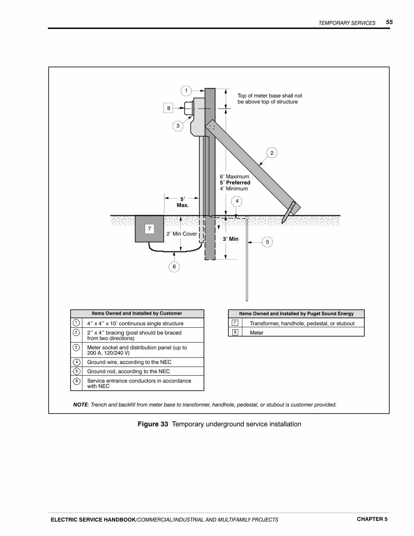
TEMPORARY SERVICES 55
ELECTRIC SERVICE HANDBOOK/COMMERCIAL/INDUSTRIAL AND MULTIFAMILY PROJECTS CHAPTER 5
Top of meter base shall notbe above top of structure
4I x 4I x 10i continuous single structure
2I x 4I bracing (post should be bracedfrom two directions)
Meter socket and distribution panel (up to200 A, 120/240 V)
Ground wire, according to the NEC
Ground rod, according to the NEC
Service entrance conductors in accordancewith NEC
1
5iMax.
3iMin2i Min Cover
4
5
Transformer, handhole, pedestal, or stubout
Meter
7
8
1
2
3
4
5
6
7
8
Items Owned and Installed by Puget Sound EnergyItems Owned and Installed by Customer
6
3
2
NOTE: Trench and backfill from meter base to transformer, handhole, pedestal, or stubout is customer provided.
6i Maximum5i Preferred4i Minimum
Figure 33 Temporary underground service installation
TEMPORARY SERVICES56
ELECTRIC SERVICE HANDBOOK/COMMERCIAL/INDUSTRIAL AND MULTIFAMILY PROJECTSCHAPTER 5
Temporary overhead services
Temp overhead service is available anywhere in PSE’s service area where the existingelectrical system is installed overhead.
The process and cost of obtaining your temp overhead service can vary depending on thelocation of our existing facilities. The least complicated and cheapest way a temp servicecan be installed is if a transformer is located on a pole alongside your property (seePreface, Figure 2). If this is the case, engineering may not be required. All you have todo is install your temp service equipment, have it inspected, and call CustomerConstruction Services (CCS) at 1-888-321-7779 to order your service. Once the aboveitems are completed, your service will be connected within a few business days.
Meter location
Your temp meter post should be located on your property and within 70 feet of the PSEpole that will serve you. This limitation ensures that your temp service pole canwithstand the weight of the conductor. If a distance greater than 70 feet is required, or ifPSE’s pole is on the opposite side of the street, please call CCS for approval prior toconstruction. A taller, stouter post with additional bracing could be required.
Service line path requirements
In addition to the meter post distance limitation mentioned above, please consider theservice line path requirements:H The path that the service line will take should not cross property belonging to other
individuals.H If the service line will pass through trees or brush, clear a path to allow our service
personnel to run the line and to allow the lines to hang without contacting trees orlimbs. Maintaining this clear path is the customer’s responsibility.
H The service line path should avoid areas where vehicular traffic will occur, unlessyour temp service post height is increased to provide adequate clearance(see Figure 34).
Clearance requirements
The National Electric Code (NEC) and the National Electric Safety Code (NESC) haveestablished minimum clearance requirements to maintain safe heights for electricalconductors over various terrains.
Figure 34 shows the clearance requirements for the types of terrain most commonlyencountered.
The NEC and NESC require the lowest point of a service conductor to be at least 12 feetaboveground. The bottom of the drip loop must be a minimum of 10 feet above theground.
You are required to provide a point of attachment on your service pole that will allowPSE to install the conductor and maintain the required clearances.
If you need further details, please consult the current issue of the NEC, or contact thestate or local electrical inspector for your area.

TEMPORARY SERVICES 57
ELECTRIC SERVICE HANDBOOK/COMMERCIAL/INDUSTRIAL AND MULTIFAMILY PROJECTS CHAPTER 5
17-1/2i
26i
TemporaryService
StateHighways
Streets, Alleys, CountyRoads, and Driveways
ResidentialProperty
12i
Service Line(Utility Owned)
10i
Figure 34 Minimum clearance requirements upon installation
Overhead temporary service installation process
The following items must be completed before we can energize your service:
1. Contact a CCS Representative and request your temp underground service.
2. Obtain an electrical work permit from the inspecting agency.
3. Install a meter pole and meter socket.
4. Obtain and pass an electrical inspection.
5. After these items are completed, call CCS and inform a CCS Representative thatyour installation has been inspected and that you are ready for temp service.
Figure 35 shows the standard temp overhead service installation that we recommend.The dimensions shown are the minimum acceptable.
This installation shows a safe temp service. Do not deviate from the installationstandards without approval from your CCS Representative. Doing so may extend thetime frame for your service hookup.
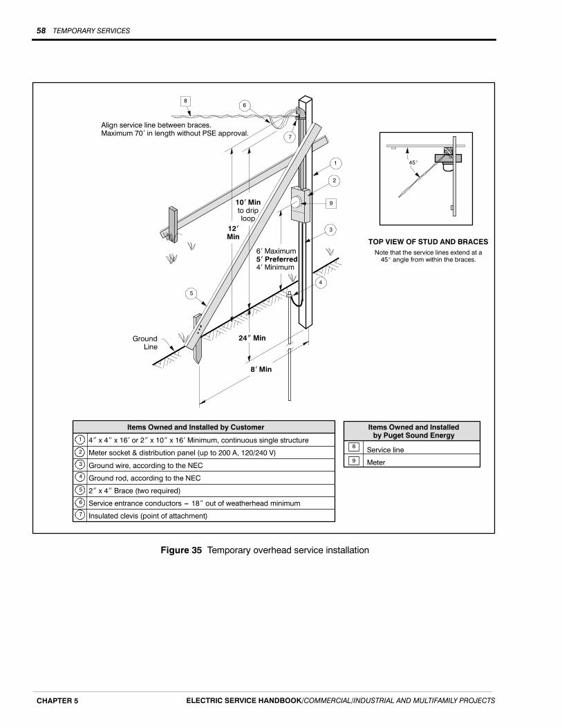
TEMPORARY SERVICES58
ELECTRIC SERVICE HANDBOOK/COMMERCIAL/INDUSTRIAL AND MULTIFAMILY PROJECTSCHAPTER 5
Items Owned and Installedby Puget Sound Energy
4I x 4I x 16i or 2I x 10I x 16i Minimum, continuous single structure
Meter socket & distribution panel (up to 200 A, 120/240 V)
Ground wire, according to the NEC
Ground rod, according to the NEC
2I x 4I Brace (two required)
Service entrance conductors --- 18I out of weatherhead minimum
Insulated clevis (point of attachment)
8
Items Owned and Installed by Customer
6
5
7
1
2
3
4
Service line
Meter
TOP VIEW OF STUD AND BRACES
Align service line between braces.Maximum 70i in length without PSE approval.
10iMinto driploop
24IMin
8iMin
6i Maximum5i Preferred4i Minimum
GroundLine
1
3
4
5
8
9
7
12iMin
6
2
45_
Note that the service lines extend at a45_ angle from within the braces.
9
Figure 35 Temporary overhead service installation
GLOSSARY 59
ELECTRIC SERVICE HANDBOOK/COMMERCIAL/INDUSTRIAL AND MULTIFAMILY PROJECTS
Glossary
Clearance - A set distance between two objects.
Conduit - A listed or approved wireway with a smooth interior surface to permit easydrawing-in of the electrical conductors. A conduit may be metallic or nonmetallic,depending on its usage, in accordance with codes and Puget Sound Energy Standards.
Corrosion Inhibitor - Electrical joint compound used to retard oxidation of electricalconnections.
Demand - The maximum average kilowatt load used by the customer for a specificperiod of time during the billing period.
Direct Burial - The installation of electrical conductors in a trench, without the use ofconduit.
EUSERC - Electrical Utility Service Equipment Requirements Committee
Guard Post - A bollard or post designed to protect the meter installation or transformerfrom vehicular traffic.
Guying - Cables or braces used to relieve the strain of overhead conductors on masts andpoles.
High Leg - (Also wild leg, delta leg) The phase leg that is at higher potential to groundthan any other two-phase legs. This leg shall be identified in red.
High-rise Building - A structure meeting the definition set forth in the InternationalBuilding Code.
Instrument Transformer - Current and/or potential transformers used in connectionwith metering equipment to monitor high current loads and/or high voltage potentials.
Keybox or Keycards - Permanently installed, locked box with keys enclosed, or akeycard screening monitor mounted on the outside of a building, for accessing thecustomer’s premises to read, install, service, or remove Puget Sound Energy metersand/or electrical equipment during reasonable working hours.
Manual Block Bypass (Circuit-Closing Block) - A provision for paralleling the metercircuit, allowing the meter to be removed without interrupting service to the customer.
Meter Jaw - A spring-loaded receptacle installed inside a meter socket, interfacing theterminals of the meter to the source and load conductors of the service.
Meter Loop - Any provision in which an electrical meter may be installed. Does notinclude the service disconnect device.
Meter Pole - A pole which supports the metering equipment owned and maintained bythe customer.

GLOSSARY60
ELECTRIC SERVICE HANDBOOK/COMMERCIAL/INDUSTRIAL AND MULTIFAMILY PROJECTS
Meter Base/Socket - The mounting device consisting of meter jaws, connectors, andenclosure for accommodating socket-type meters. The mounting device may be either asingle socket or a trough to accommodate more than one mounting unit.
Multifamily Building - A single structure comprised of two or more independentdwelling units having permanent provisions for living, sleeping, cooking, and sanitation.
Municipal or State Inspector - The qualified representative of a city or the State ofWashington Department of Labor and Industries, who has been authorized bygovernmental agencies to inspect electrical service installations on their behalf.
NEC - National Electrical Code
Nonresidential Buildings - All structures that are not residential buildings, multifamilybuildings, or where portions of such a building are intended for commercial, retail, orgeneral public activities.
Point of Attachment - The point at which Puget Sound Energy’s service conductors areattached to the customer’s premises by an approved insulated clevis.
Point of Delivery - The location on the customer’s premises where Puget SoundEnergy’s circuit and the customer’s system are interconnected.
RCW - Revised Code of Washington
Safety Socket - A three-phase self-contained meter base socket with provisions tode-energize the meter base without disconnecting the load.
Seal - The locking device used to secure meter and/or service entrance equipment toensure safety and security for the unit.
Secondary Voltage - The lower voltage, after transformation, used to supply thecustomer with electrical energy. Normally less than 600 V.
Self-Contained - In reference to meter sockets: a device designed and rated tocontinuously carry the entire capacity of the service entrance equipment through themeter.
Service Entrance Conductors - Those conductors which extend between the customer’sload center and point of delivery.
Service Entrance Equipment - Service conduit, conductors, weatherhead, meter base,enclosures, service disconnect, and load center.
Service Mast - The conduit above the meter used to provide mechanical protection forthe service conductors and to support the service drop from PSE’s system.
Temporary Service - An electrical service installed by Puget Sound Energy to providepower to a customer on a temporary basis (12 months or less).
WAC - Washington Administrative Code