![First Revision No. 1-NFPA 79-2016 [ Global Input ] · PDF fileIEC 60072–2, Dimensions and output series for rotating electrical machines — Part 2: Frame numbers 355 to 1000 and](https://static.fdocuments.us/doc/165x107/5a9f52a87f8b9a71178c9dc6/first-revision-no-1-nfpa-79-2016-global-input-600722-dimensions-and-output.jpg)
ELECTRIC MOTORS - BARTEC · PDF fileIEC 60072-2 European Directives Description Directive...
132
ELECTRIC MOTORS
Transcript of ELECTRIC MOTORS - BARTEC · PDF fileIEC 60072-2 European Directives Description Directive...

BARTEC GmbH
Max-Eyth-Str. 16 97980 Bad Mergentheim Germany
Phone: +49 7931 597 0 Fax: +49 7931 597 119 [email protected] www.bartec.de
ELECTRIC MOTORS
BARTEC VARNOST d.o.o.
Cesta 9, avgusta 59 1410 Zagorje ob Savi Slovenia
Phone: +386 59 221 471 Fax: +386 59 221 470 [email protected] www.bartec-varnost.si
ELEC
TRIC
MOT
ORS
201
7
UK-D
-BM
E131
0201
7-10
/201
7-M
arke
ting
& Co
mm
unic
atio
ns-4
1566
9


1
2
3
4
5
FLAMEPROOF ELECTRICAL MOTORS SERIES 4KTC
FLAMEPROOF BRAKE MOTORS SERIES BM 4KTC
NEMA EXPLOSION-PROOF MOTORS SERIES 4KTU
SUBMERSIBLE MOTORS SERIES 4KTS
MINING MOTORS SERIES 4KTCR AND 4KTCP
ELECTRIC MOTORS


BARTEC 03-0330-0707/A-10/2017-BAT-344828/2 3
FLAMEPROOF ELECTRICAL MOTORS, SERIES 4KTC

BARTEC VARNOST4
IGNITION TEMPERATURE - TEMPERATURE CLASS 6
MAINTENANCE OF EXPLOSION PROTECTION 6
CONSTRUCTION Dimensions
Type codes
Bearings
Shaft ends
Allowable radial force
Maximum axial loads
Noise level and vibrations
Terminal box and terminals for supply cable
Mechanical protection and coating
Arrangements
Explosion protection and certificates
Electrical datas
Windings
Test and tolerance band of the rated values
Start-up characteristics
Duty cycles
Tables with ratings for single-speed motors
Technical data and tables with ratings for pole changing motors
Three phase motors supplied by frequency inverters
Mounting dimensions
Dimensions
Special execution
8
8
9 - 10
10
10
11
11
12 - 13
14
15
15
16
17
18
19
19 - 20
21 - 28
29 - 42
43 - 47
48
49 - 53
54 - 57
SPECIAL APPLICATIONS/OPTIONS 58
CONTENTS

BARTEC VARNOST6
Temperature class
Ignition temperature range of mixture
Permissible surface temperature of electrical equipment
Permissible temperature rise
T1 > + 450 °C + 450 °C + 410 °C
T2 > + 300... ≤ + 450 °C + 300 °C + 260 °C
T3 > + 200... ≤ + 300 °C + 200 °C + 160 °C
T4 > + 135... ≤ + 200 °C + 135 °C + 95 °C
T5 > + 100... ≤ + 135 °C + 100 °C + 60 °C
T6 > + 85... ≤ + 100 °C + 85 °C + 45 °C
Examples of the categorisation of gases and vapours in temperature classes and explosion protection subgroups.
T1 T2 T3 T4 T5 T6
IIA Methane Propane PetrolAcetalde-hyde
IIB EthyleneDiethyl-ether
IIC Hydrogen AcetyleneCarbon disulphide
Duty type Type of protection
S1* A
B
C
Motor safety switch according to IEC 60034-1 (VDE 0165/9.83)
Motor safety switch and temperature sensors in windings as additional protection.
Only temperature sensors as major protection only allowed if motor is tested and certified and if all control devices (power supplies) used are certified.
S2/S3* D
E
Motor safety switch with switch-on time control and/or temperature sensors in windings as additional protection.
Temperature sensors in windings as major protection. Only allowed if motor is tested and certified and if all control devices (power supplies) used are certified.
S4, S5, S6, S7, S8* F Temperature sensors in windings. Motor must be tested and only certified control devices may be used.
Power supply by means of frequency converters
G
H
Thermal protection of motor by means of sensors in windings is allowed as the only (independent) protection if motor is testedat all power supply frequencies, maximum voltage and S1-S7 (S8) types of operation.
If motor protection and converter are tested and certified as a unit.
* For explanation of duty cycles see chapter “duty cycles“.
IGNITION TEMPERATURE - TEMPERATURE CLASS
The ignition temperature is influenced by various factors such as size, shape, type and composition of a surface. In IEC 79-4, IEC, CENELEC and other standards the authorities have agreed on a ”procedure for the determination of ignition temperature” with a limit approaching the lowest possible value.The gases and vapours are classified into temperature classes. In accordance with these temperature classes, electrical equipment is tested for its maximum surface temperature to ensure that the possibility of ignition due to the surface temperature is excluded in normal and abnormal operation. The standards specify to which extent these standard values may be exceeded and determine the necessary safety margins.
MAINTENANCE OF EXPLOSION PROTECTION
Maintenance of explosion protection during operation. Electric machines must be protected against overheating due to overloads. The type of protection depends on the type of operation as well as the electric machine and its use. Explosion-proof electric motors are usually certified for S1 type of operation, i. e. continuous operation. Other duties are allowed only if the temperature of the motor is controlled by reliable devices.
Temperature class
Ignition temperature - temperature class/Maintenance of explosion protection
BARTEC VARNOST 7
1
Ignition temperature - temperature class/Maintenance of explosion protection
Standard IEC international
EN-CENELEC Europe
Rotating electric machines - classification of insulation materials for electric machines
IEC 60034-1 EN 6O034-1
Climatic protection (IP number) Protection against harmful contact and ingress of solids
IEC 60034-5 EN 6O034-5
Cooling devices for electric machines
IEC 60034-6 EN 6O034-6
Construction and mounting of electric rotating machines
IEC 60034-7 EN 6O034-7
Marking of terminals and directions of rotating of electric machines
IEC 60034-8 EN 6O034-8
Noise levels IEC 60034-9 EN 6O034-9
Starting perfomances of short-circuit motors at 50 Hz and voltages up to 660 V
IEC 60034-12 EN 60034-12
Limited vibration levels for electric machines
IEC 60034-14 EN 60034-14
Relation between terminal sizes and ratings of three-phase short-circuit surface-cooled electric motors
IEC 60072-1, DIN 42673/3
Relation between terminal sizes and ratings for arrangements: IM B5, IM B10, IM B14
IEC 60072-2
European Directives
Description Directive
Directive for explosive atmospheres (ATEX) 94/9/EG,1999/92/EL
Electromagnetic Compatibility (EMC) 2004/108/EG
Low Voltage Directive (LVD) 2006/95/EG
Machinery Directive 2006/42/EG
Packing and packaging waste 2005/20/EG
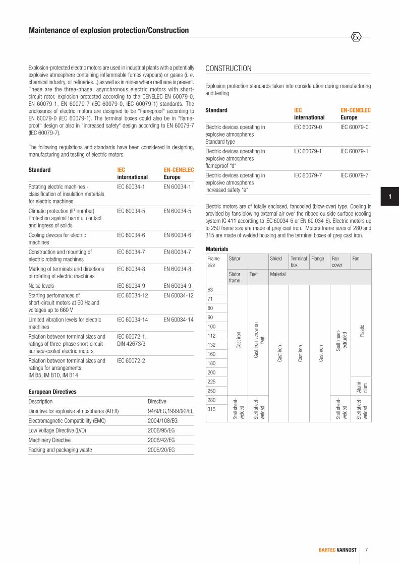
Explosion-protected electric motors are used in industrial plants with a potentially explosive atmosphere containing inflammable fumes (vapours) or gases (i. e. chemical industry, oil refineries...) as well as in mines where methane is present.These are the three-phase, asynchronous electric motors with short-circuit rotor, explosion protected according to the CENELEC EN 60079-0, EN 60079-1, EN 60079-7 (IEC 60079-0, IEC 60079-1) standards. The enclosures of electric motors are designed to be “flameproof“ according to EN 60079-0 (IEC 60079-1). The terminal boxes could also be in “flame-proof“ design or also in “increased safety“ design according to EN 60079-7 (IEC 60079-7).
The following regulations and standards have been considered in designing, manufacturing and testing of electric motors:
CONSTRUCTION
Explosion protection standards taken into consideration during manufacturing and testing
Standard IEC international
EN-CENELEC Europe
Electric devices operating in explosive atmospheres Standard type
IEC 60079-0 IEC 60079-0
Electric devices operating in explosive atmospheres flameproof “d“
IEC 60079-1 IEC 60079-1
Electric devices operating in explosive atmospheres Increased safety “e“
IEC 60079-7 IEC 60079-7
Electric motors are of totally enclosed, fancooled (blow-over) type. Cooling is provided by fans blowing external air over the ribbed ou side surface (cooling system IC 411 according to IEC 60034-6 or EN 60 034-6). Electric motors up to 250 frame size are made of grey cast iron. Motors frame sizes of 280 and 315 are made of welded housing and the terminal boxes of grey cast iron.
Materials
Frame size
Stator Shield Terminal box
Flange Fan cover
Fan
Stator frame
Feet Material
63
Cast
iron
Cast
iron
-scr
ew o
n fe
et
Cast
iron
Cast
iron
Cast
iron St
ell s
heet
- ex
trude
d Plas
tic
71
80
90
100
112
132
160
180
200
225
Alum
i-ni
um
250
280
Stel
l she
et-
weld
ed
Stel
l she
et-
weld
ed
Stel
l she
et-
weld
ed
Stel
l she
et-
weld
ed315
Maintenance of explosion protection/Construction
BARTEC VARNOST8
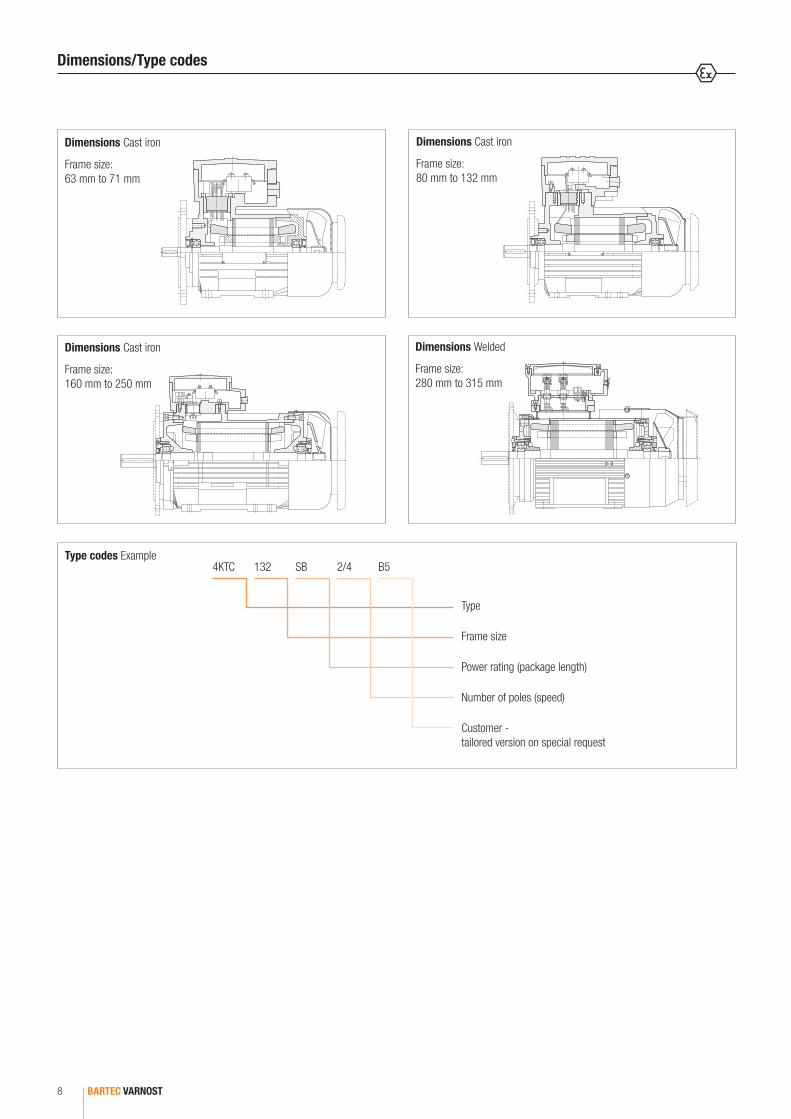
Dimensions Cast iron
Frame size: 63 mm to 71 mm
4KTC 132 SB 2/4 B5
Type
Frame size
Power rating (package length)
Number of poles (speed)
Customer - tailored version on special request
Type codes Example
Dimensions Cast iron
Frame size: 80 mm to 132 mm
Dimensions Cast iron
Frame size: 160 mm to 250 mm
Dimensions Welded
Frame size: 280 mm to 315 mm
Dimensions/Type codes

BARTEC VARNOST 9
1
Frame size
Poles DE bearing
NDE bearing
Bearing dishes
63 2 to 8 6201 2Z C3 6201 2Z C3 12 x 32 x 10
71 2 to 8 6203 2Z C3 6203 2Z C3 17 x 40 x 12
80 2 to 8 6204 2Z C3 6204 2Z C3 20 x 47 x 14
90 2 to 8 6205 2Z C3 6205 2Z C3 25 x 52 x 15
100 2 to 8 6206 2Z C3 6206 2Z C3 30 x 62 x 16
112 2 to 8 6206 2Z C3 6206 2Z C3 30 x 62 x 16
132 2 to 8 6208 2Z C3 6208 2Z C3 40 x 80 x 18
160 2 to 8 6309 2Z C3 6309 2Z C3 45 x 100 x 25
180 2 to 8 6310 2Z C3 6310 2Z C3 50 x 110 x 27
200 2 to 8 6312 2Z C3 6312 2Z C3 60 x 130 x 31
225 2 to 8 6313 2Z C3 6313 2Z C3 65 x 140 x 33
250 2 to 8 6314 2Z C3 6314 2Z C3 70 x 150 x 35
280 2 to 8 6316 2Z C3 6316 2Z C3 80 x 170 x 39
315 2 to 8 NU 317 C3 *6317 2Z C3
6317 2Z C3 85 x 180 x 41
* roller bearings from frame size 160 ** isolated bearing from frame size 250
Bearing lubrication
The following table lists the bearings used in the different motors. The bearings last about 20.000 hours in 4, 6 and 8 pole motors if the loads do not exceed the values indicated in the tables on pages 12 and 13. Only the latest and most innovative bearings of known producers have been used in our motors. On customer request we equip the motors with other bearings (depends on the respective construction!). The rotors are standard constructions and fixed on the D-end (frame size 71 mm to 250 mm) and NDE-end (frame size 280 mm to 315 mm).
Bearing assemblies Drive end
4KTC 63 to 132 4KTC 160 to 250
4KTC 280 4KTC 315
Bearing assemblies Non-drive end
4KTC 63 to 132 4KTC 160 to 250
4KTC 280 4KTC 315
Ball Bearing: Lubrication intervals in duty hours
Frame size
Amount of Grease [g]
Speed of the motor [min-1]
3600 3000 1800 1500 1000 500
160 25 7000 9500 14000 17000 21000 24000
180 30 6000 8000 13500 16000 20000 23000
200 40 4000 6000 11000 13000 17000 21000
225 50 3000 5000 10000 12500 16500 20000
250 60 2500 4000 9000 11500 15000 18000
280 70 2000 3500 8000 10500 14000 17000
315 90 2000 3500 6500 8500 12500 16000
Motors are normally fitted with permanently greased bearings of Type 2Z. According to experience the filled in grease will be sufficient for several years.
Motors fitted with grease nipples
Motors from frame size 160 and above can be fitted with regreasable bearings. For motors with lubrication system we recommend not to exceed lubrication interval of two years in any case. Lubricate the motor when operational. If the motor is fitted with a lubrication plate, use values given, or use values given in the table below. These values are according to L1 – principle. The effectivness of motor lubrication should be checked by measuring the surface temperature of bearing endshield during normal operating conditions. If the measured temperature is +80 °C or above, the relubrication intervals must be shortened. Relubrication interval should be halfened for every 15 K increase in bearing temperature. If this is not possible then use the lubricants suitable for high operation temperature conditions.
Roller Bearing: Lubrication intervals in duty hours
Frame size
Amount of Grease [g]
Speed of the motor [min-1]
3600 3000 1800 1500 1000 500
315 45 1000 1700 3000 4300 6000 8000
Bearings
BARTEC VARNOST10
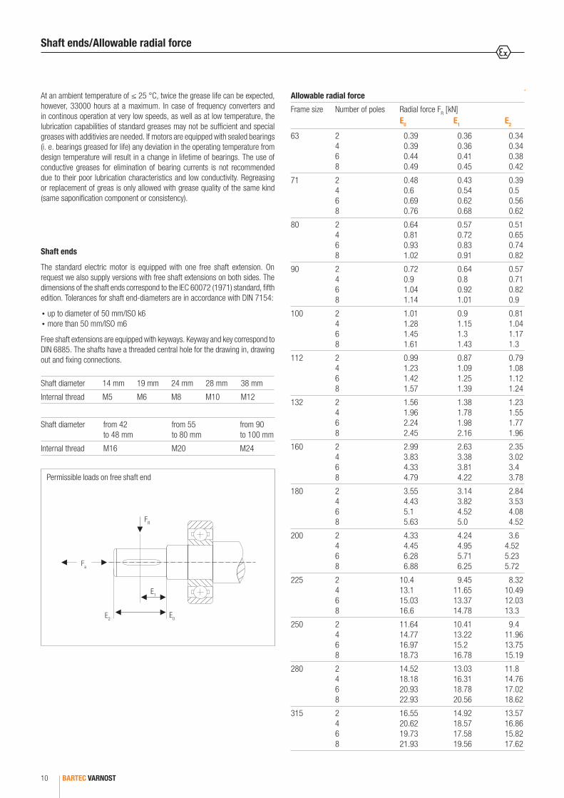
At an ambient temperature of ≤ 25 °C, twice the grease life can be expected, however, 33000 hours at a maximum. In case of frequency converters and in continous operation at very low speeds, as well as at low temperature, the lubrication capabilities of standard greases may not be sufficient and special greases with additivies are needed. If motors are equipped with sealed bearings (i. e. bearings greased for life) any deviation in the operating temperature from design temperature will result in a change in lifetime of bearings. The use of conductive greases for elimination of bearing currents is not recommended due to their poor lubrication characteristics and low conductivity. Regreasing or replacement of greas is only allowed with grease quality of the same kind (same saponification component or consistency).
Shaft ends The standard electric motor is equipped with one free shaft extension. On request we also supply versions with free shaft extensions on both sides. The dimensions of the shaft ends correspond to the IEC 60072 (1971) standard, fifth edition. Tolerances for shaft end-diameters are in accordance with DIN 7154:
up to diameter of 50 mm/ISO k6more than 50 mm/ISO m6
Free shaft extensions are equipped with keyways. Keyway and key correspond to DIN 6885. The shafts have a threaded central hole for the drawing in, drawing out and fixing connections.
Fa
E2E0
E1
FR
Permissible loads on free shaft end
Allowable radial force
Frame size Number of poles Radial force FR [kN] E0 E1 E2
63 2468
0.39 0.39 0.44 0.49
0.36 0.36 0.41 0.45
0.34 0.34 0.38 0.42
71 2468
0.48 0.6 0.69 0.76
0.43 0.54 0.62 0.68
0.39 0.5 0.56 0.62
80 2468
0.64 0.81 0.93 1.02
0.57 0.72 0.83 0.91
0.51 0.65 0.74 0.82
90 2468
0.72 0.9 1.04 1.14
0.64 0.8 0.92 1.01
0.57 0.71 0.82 0.9
100 2468
1.01 1.28 1.45 1.61
0.9 1.15 1.3 1.43
0.81 1.04 1.17 1.3
112 2468
0.99 1.23 1.42 1.57
0.87 1.09 1.25 1.39
0.79 1.08 1.12 1.24
132 2468
1.56 1.96 2.24 2.45
1.38 1.78 1.98 2.16
1.23 1.55 1.77 1.96
160 2468
2.99 3.83 4.33 4.79
2.63 3.38 3.81 4.22
2.35 3.02 3.4 3.78
180 2468
3.55 4.43 5.1 5.63
3.14 3.82 4.52 5.0
2.84 3.53 4.08 4.52
200 2468
4.33 4.45 6.28 6.88
4.24 4.95 5.71 6.25
3.6 4.52 5.235.72
225 2468
10.4 13.1 15.03 16.6
9.45 11.65 13.37 14.78
8.3210.4912.0313.3
250 2468
11.64 14.77 16.97 18.73
10.41 13.22 15.2 16.78
9.411.9613.7515.19
280 2468
14.52 18.18 20.93 22.93
13.03 16.31 18.78 20.56
11.814.7617.0218.62
315 2468
16.55 20.62 19.73 21.93
14.92 18.57 17.58 19.56
13.5716.8615.8217.62
Shaft diameter 14 mm 19 mm 24 mm 28 mm 38 mm
Internal thread M5 M6 M8 M10 M12
Shaft diameter from 42 to 48 mm
from 55 to 80 mm
from 90 to 100 mm
Internal thread M16 M20 M24
Shaft ends/Allowable radial force

BARTEC VARNOST 11
1
The load rating of bearings has been calculated for at least 20 000 operating hours at a frequency of 50 Hz. Only the axial loads have been considered. If the load is made up of axial and radial loads, the working life of the bearings is shorter.
Maximum loads for free shaft extension FA [kN]
Mounting arrangements
IM B7 IM B8 IM B14 IM B34 IM V18 IM V19 IM V1 IM V3 IM V5 IM V6
IM B3 IM B35 IM B5 IMJ B6 Weight of rotor in load direction Weight of rotor in opposite load direction
Speed 3000 1500 1000 750 3000 1500 1000 750 3000 1500 1000 750
63 0.26 0.26 0.31 0.34 0.27 0.27 0.32 0.35 0.13 0.13 0.15 0.17
71 0.27 0.34 0.39 0.43 0.33 0.43 0.47 0.52 0.35 0.46 0.51 0.55
80 0.36 0.45 0.52 0.57 0.43 0.55 0.62 0.69 0.47 0.6 0.69 0.76
90 0.41 0.51 0.59 0.65 0.48 0.61 0.69 0.77 0.54 0.68 0.79 0.86
100 0.55 0.69 0.79 0.88 0.64 0.81 0.92 1.03 0.75 0.94 1.07 1.11
112 0.55 0.69 0.79 0.88 0.63 0.77 0.89 1.0 0.76 0.98 1.1 1.14
132 0.83 1.04 1.2 1.32 0.92 1.13 1.3 1.48 1.16 1.47 1.67 1.82
160 1.52 1.91 2.19 2.41 1.65 2.1 2.4 2.65 2.13 2.68 3.08 3.31
180 1.77 2.24 2.56 2.82 1.85 2.3 2.71 3.0 2.55 3.26 3.74 4.13
200 2.33 2.94 3.37 3.71 2.39 3.06 3.54 3.89 3.45 4.38 4.91 5.5
225 2.66 3.36 3.85 4.23 2.71 3.3 3.78 4.25 4.03 5.05 5.94 6.28
250 2.98 3.76 4.30 4.73 2.92 3.85 4.07 4.48 4.62 5.55 6.81 7.46
280 3.50 4.41 5.05 5.56 3.18 3.76 4.52 4.82 5.51 7.13 7.94 8.89
315 3.58 4.51 5.17 5.69 2.33 2.31 2.01 2.55 6.09 8.15 9.34 10.05
Maximum axial loads/Noise level and vibrations
Maximum noise level L dB allowed at 1 m distance from the machine surface, Values for fan-cooled (blow-over) machines; IP 44
Power ratings P (kW)
Rotation speed min-1
600 < n 960 960 < n 1320 1320 < n 1900 1900 < n 2360 2360 < n 3150 3150 < n 3750
P < 1.1 67 70 71 74 75 79
1.1 < P < 2.2 69 70 73 78 80 82
2.1 < P < 5.5 72 74 77 82 83 85
5.5 < P < 11 75 78 81 86 87 90
11 < P < 22 78 82 85 87 91 93
22 < P < 37 80 84 86 89 92 95
37 < P < 55 81 86 88 92 94 97
55 < P < 110 84 89 92 93 96 98
110 < P < 220 87 91 94 96 98 100
Vibrations
The noise level of electric motors is below the limits prescribed by the IEC 60034-9 recommendation for fan-cooled (blow-over) electric machines. The rotors of electric motors are dynamically balanced with installed fan and 1/2 key. Vibration amplitude corresponds to grade A according to IEC 60034-14 (ISO 2373-N grade).
Grade “A“ applies to machines with no special vibration requirements Grade “B“ applies to machines with special vibration requirements
Limit values for the vibration of electric machines (IEC 60034-14)
Vibration grade Shaft height [mm] 56 H 132 132 < H 280 H > 280
Mounting Velocity [mm/s]
A Free suspension 1.6 2.2 2.8
Rigid mounting 1.3 1.8 2.3
B Free suspension 0.7 1.1 1.8
Rigid mounting - 0.9 1.5

BARTEC VARNOST12
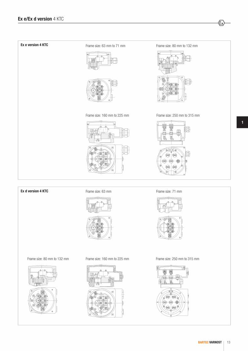
Terminal boxThe terminal box is fitted to the top of the motor with the cable entering from the fan end of the motor. It can be repositioned in steps of 90° to 180° to suit the application. The motors with direct starting are equipped with 3 connection terminals. 6 connection terminals are fitted to Star-Delta, two speed and dual voltage machines. The electric motors with sizes 71 to 132 inclusive and Ex e terminal boxes have 6 additional connection terminals for PTC sensors, heaters etc. The motors with Ex d terminal boxes are also equipped with 6 connection terminals. Exception is the 71 motor with only 4 connection terminals. Each terminal box has one connection terminal for the protective conductor. Ex d terminal boxes include a threaded entry to accept Ex d cable glands (see table below). Ex d thread reducers or adaptors can be included as an option for other thread sizes and thread forms.
Increased safety terminal boxes incl de Ex e cable glands in accordance with EN 60079-0, and EN 60079-7. The empty entries are fitted with suitably certified stopping plugs. Additional entries can only be made in our factory under strict quality procedures. The Ex d terminal may receive additional threaded holes (NPT, ISO 7/1) by means of adapters. One threaded hole M20 x 1.5 is provided on the Ex d terminal boxes for the thermal protection and for heaters. Ex e terminal boxes have an additional cable gland M20 x 1.5 for cable diameters of 6 to 12 mm.
Terminals for supply cable and cable entries
Frame size Terminals for a max. cross section of supply cable (mm2)
Cable entries for main connection
Ex e terminal box Ex d terminal box
Cable glands (with Ex e cable glands) External diameter of supply cable Cable entries (without cable glands)
63 2.5 1 x M20 x 1.5 6 to 13 1 x M20 x 1.5
71 2.5 1 x M20 x 1.5 6.5 to 12 1 x M20 x 1.5
80 90 100
4 1 x M25 x 1.5 10 to 17 1 x M25 x 1.5
112 4 1 x M32 x 1.5 13 to 18 1 x M32 x 1.5
132 4 2 x M32 x 1.5 13 to 18 2 x M32 x 1.5
160 180
16 2 x M40 x 1.5 17 to 28 2 x M40 x 1.5
200 225
16 2 x M50 x 1.5 23 to 38 2 x M50 x 1.5
250 280 315
95 to 300 2 x M63 x 1.5 31 to 48 2 x M63 x 1.5
Additional one cable entrie (gland) M20 x 1.5 for PTC
Terminal box and terminals for supply cable
BARTEC VARNOST 13
1
Frame size: 63 mm to 71 mm Frame size: 80 mm to 132 mm
Frame size: 250 mm to 315 mm
Ex e version 4 KTC
Ex d version 4 KTC Frame size: 71 mm
Frame size: 80 mm to 132 mm Frame size: 160 mm to 225 mm Frame size: 250 mm to 315 mm
Frame size: 160 mm to 225 mm
Frame size: 63 mm
Ex e/Ex d version 4 KTC

BARTEC VARNOST14
IP protection
IP protection of electric motors corresponds to IP 55. Motors with a higher degree of IP protection are manufactured on special request.
Protection against environmental influences, IP protection
IP protection Protection against harmful contact and ingress of solids (1st Numeral)
IP 44 Protection against direct contact with electrically live and rotating inner parts using tools, wire or similar objects with a diameter exceeding 1 mm. Protection against ingress of solids (diameter > 1 mm). Fan air outlets and water exhausts may have a second-degree level of protection.
IP 54/IP 55/IP 56 Complete protection against contact with electrically live and moving rotating inner parts. Protection against harmful ingress of dust. Ingress of dust is not fully pre-vented, but must not reach an extend causing harmful effects to machine operation.
IP 65* Complete protection against contact with electrically live parts and rotating inner parts. Protection against ingress of dust (dust-proof machine).
IP protection Protection against ingress of water (2nd Numeral)
IP 44/IP 54 Water particles spraying from any direction do not have any harmful effects on the machine (i. e. rain).
IP 55/IP 65* A jet of water spraying from any direction does not have any harmful effects on the machine.
IP 56 During rough seas water must not penetrate into the interior of the motor to such an extend as to cause damage to the machine (deck-mounted motors).
* All vertically-mounted electric motors with free shaft extension on the top must be protected against particles falling into the fan cover. This protection is not necessary if the machine itself has such a protection. Electric motors mounted outdoors must be protected against exposure to direct sunlight.
Coating - Surface protection against evironmental influences
Anti-corrosion protection 2 (standard) Anti-corrosion protection 3 (special) Special surface protection
Surface sanding and degreasing sanding and degreasing Products with surface protection for marine/offshore and tropical conditions are available on special request
Undercoating Avtol Avtol
Intermediate Coating 1 - Epoxy
Intermediate Coating 2 - Epoxy
Finishing Korvin Epoxy
Total thickness (mm) 80 140
Colour* blue RAL 5010 blue RAL 5010
Protection against corrosion in enviroments with watter
high humidity, steam, sea water high humidity, steam, sea water
Enviroments resistance periodic spilling or spraying of anorganic acids and lyes
periodic spilling or spraying of anorganic acids and lyes
Suitable for normal industrial atmospheres, relatively high humidity and high concent. of salt and aggressive gases (SO2, NOx)
Chemically agressive atmospheres, high concent. of salt and aggressive gases (SO2, NOx). Condensation of moisture and electrolytes on surface. Solvents and oil derivates have negative effects.
* Mining industry: yellow RAL 1003 for 500 V, grey RAL 9003 for 1000 V
Degrees of IP protection and coating

BARTEC VARNOST 15
1
The types of electric motors and their symbols are prescribed by the IEC 60034-7, EN 60034-7 standards. Motors are manufactured following the basic IM B3, IM B5 and IM B14 types. Table 4 shows the symbols and mounting arrangements for the standard models manufactured by our company. IM B3 type motors can also operate in IM B6, IM B7 and IM B8 mounting positions.
IEC code I IM B3 IM B5 IM B34 IM B14 IM B35IEC code II IM 1001 IM 3001 IM 2101 IM 3601 IM 2001
IEC code I IM V6 IM V3 IM V6/IM V19 IM V19 IM V36IEC code II IM 1031 IM 3031 IM 3631 IM 2031
IEC code I IM V5 IM V1 IM V5/IM V18 IM V18 IM V15IEC code II IM 1011 IM 3011 IM 3611 IM 2011
Arrangements/Explosion protection and certifications
Explosion protection
Markings
frame size 63 II 2G Ex db II(B)C T4-T6 Gb or II 2G Ex db e II(B)C T4-T6 Gb II 2D Ex tb III(B)C T135-85°C Db
frame sizes 71 to 225 II 2G Ex d II(B)C T4-T6 Gb or II 2G Ex d e II(B)C T4-T6 Gb II 2D Ex tb IIIC T135-85°C Db
frame size 250 II 2G Ex db II(B)C T4-T6 Gb or II 2G Ex db eb II(B)C T4-T6 Gb II 2D Ex tb IIIC T135-85°C Db
frame size 280 and 315 II 2G Ex db II(B)C T4-T6 Gb or II 2G Ex db e II(B)C T4-T6 Gb
Certifications
frame size 63 SIQ 15 ATEX 084 X / IECEx SIQ 15.0002 X
frame sizes 71 to 225 BVS 13 ATEX E 125 X / IECEx BVS 13.0121 X
frame size 250 BVS 16 ATEX E 129 X / IECEx BVS 16.0095 X
frame size 280 and 315 BVS 15 ATEX E 075 X / IECEx BVS 15.0066 X

BARTEC VARNOST16
Power, voltage and frequency
The power ratings given in the tables are valid for operation under uniform, continuous load (S-1 according to IEC 60034-1, EN 60034-1) at a rated voltage, a frequency of 50 Hz, temperatures of up to +40 °C and an altitude of less than 1 000 m above sea level. The data in the tables refer to 400 V, but motors have been designed for 380 V and 415 V. Voltage or frequency variations of +/- 5 % are allowed; within these limits the power ratings remain unchanged and the maximum winding temperature is not exceeded. Versions using 110 V to 1 000 V and frequencies of 50 or 60 Hz are available on special request. 50 Hz, 380 V, 400 V, 415 V electric motors may also be connected to 440 V to 480 V and a frequency of 60 Hz. Then the maximum load can be increased by 15 % and the number of revolutions by approximately 20 %. If a 50 Hz, 380 V, 400 V, 415 V electric motor is connected to a 60 Hz line, its maximum load may not exceed the nominal power. The number of revolutions increases by 20 %, while the starting and maximum torque decreases by approx. 18 %.
Efficiency η (%) of the rate load Power factor cos ϕ of the rate load
5/4 4/4 3/4 2/4 5/4 4/4 3/4 2/4
96959493929190898886858483828179787776757473727170696867666564
96959493929190898887868584838281807978777675747372717069686766
9695949392919089838786858483828180797877767574737271706967.566.565
94.593.392919089878685.58584.584838180.580797876757473727169686766646261
0.940.940.920.910.90.890.880.880.870.860.860.850.850.830.820.820.790.780.780.770.760.750.740.730.720.710.70.70.680.680.67
0.940.930.920.910.90.890.880.870.860.850.840.830.820.810.80.790.780.770.760.750.740.730.720.710.70.690.680.670.660.650.64
0.920.920.890.880.870.880.850.840.830.820.810.80.780.760.750.730.730.720.70.690.670.660.650.640.630.620.610.590.570.550.54
0.740.680.650.640.630.60.580.570.550.530.510.490.470.450.430.420.410.40.380.360.360.350.340.340.330.330.320.30.30.30.3
Electrical datas
Overload, efficiency and power factor
Electric motors heated to the operating temperature limit resist to a 2-minute overload of 1.5 In without being damaged. Variations between the 5/4 and 3/4 of the rated load have no essential influence on efficiency and power factor.
BARTEC VARNOST 17
1
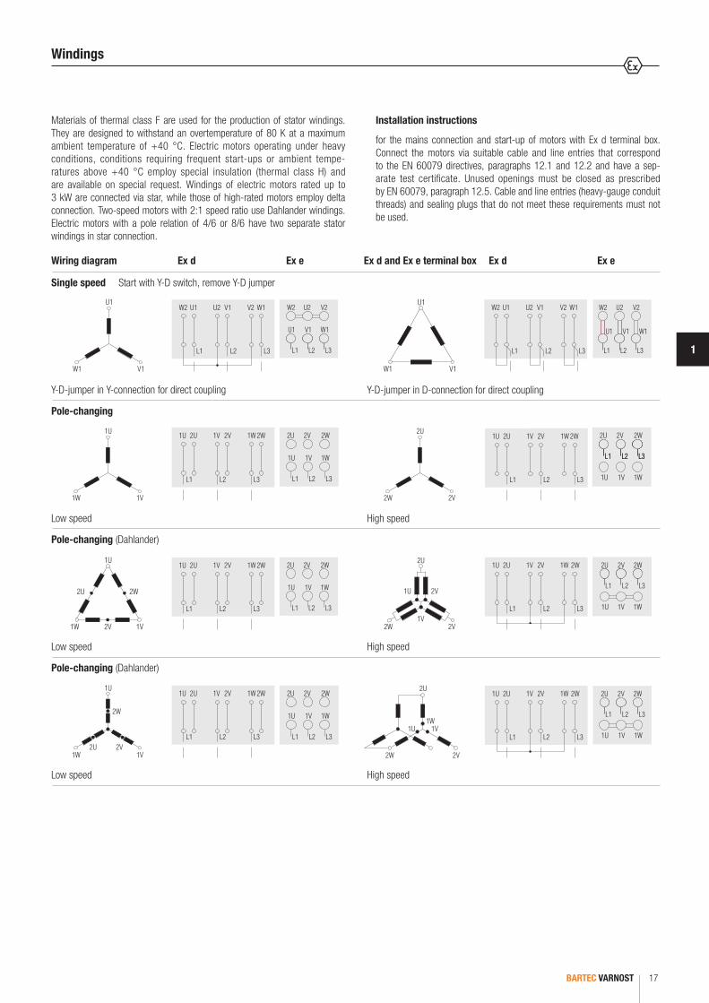
Materials of thermal class F are used for the production of stator windings. They are designed to withstand an overtemperature of 80 K at a maximum ambient temperature of +40 °C. Electric motors operating under heavy conditions, conditions requiring frequent start-ups or ambient tempe-ratures above +40 °C employ special insulation (thermal class H) and are available on special request. Windings of electric motors rated up to 3 kW are connected via star, while those of high-rated motors employ delta connection. Two-speed motors with 2:1 speed ratio use Dahlander windings. Electric motors with a pole relation of 4/6 or 8/6 have two separate stator windings in star connection.
Installation instructions
for the mains connection and start-up of motors with Ex d terminal box. Connect the motors via suitable cable and line entries that correspond to the EN 60079 directives, paragraphs 12.1 and 12.2 and have a sep-arate test certificate. Unused openings must be closed as prescribed by EN 60079, paragraph 12.5. Cable and line entries (heavy-gauge conduit threads) and sealing plugs that do not meet these requirements must not be used.
Wiring diagram Ex d Ex e Ex d and Ex e terminal box Ex d Ex e
Y-D-jumper in Y-connection for direct coupling Y-D-jumper in D-connection for direct coupling
Single speed Start with Y-D switch, remove Y-D jumper
Low speed High speed
Pole-changing
Low speed High speed
Pole-changing (Dahlander)
Low speed High speed
Pole-changing (Dahlander)
Windings
BARTEC VARNOST18
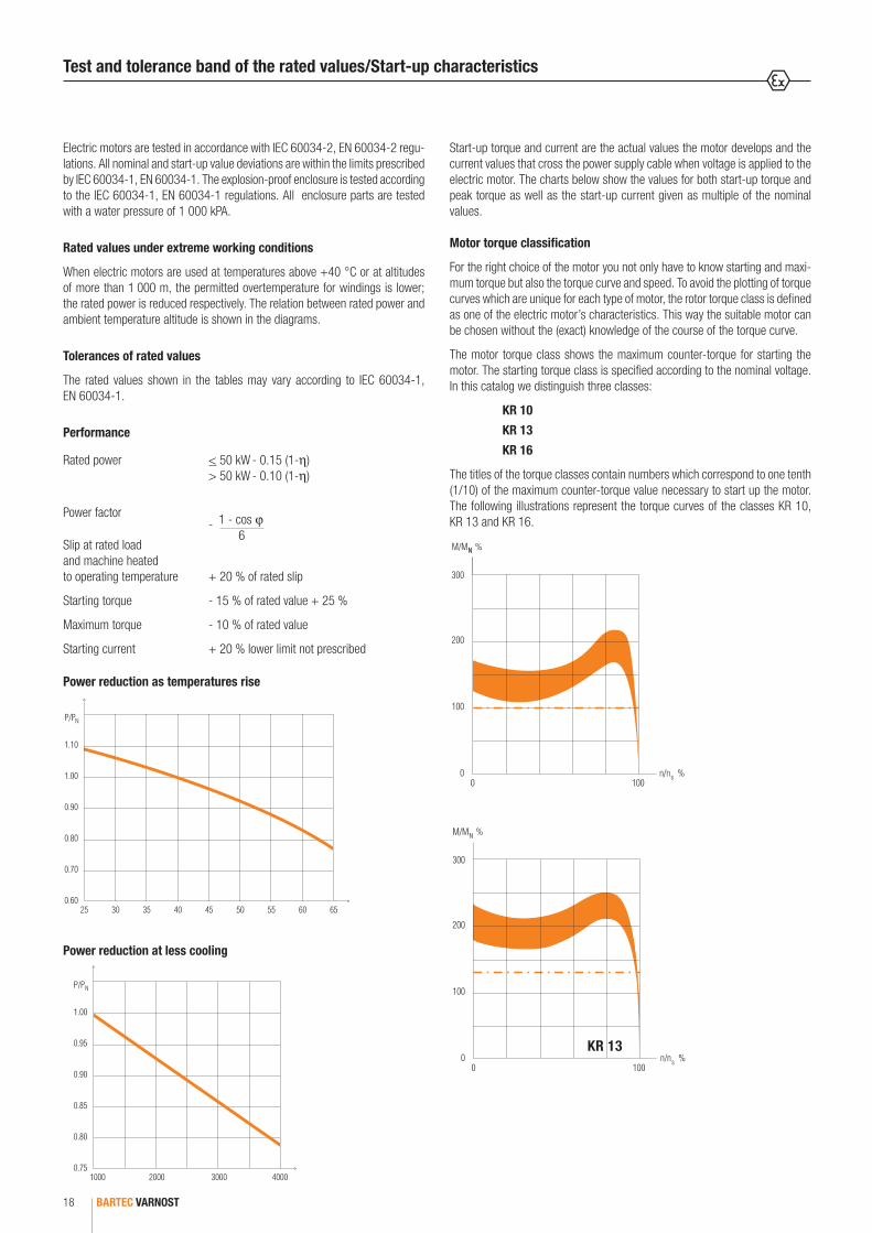
Electric motors are tested in accordance with IEC 60034-2, EN 60034-2 regu-lations. All nominal and start-up value deviations are within the limits prescribed by IEC 60034-1, EN 60034-1. The explosion-proof enclosure is tested according to the IEC 60034-1, EN 60034-1 regulations. All enclosure parts are tested with a water pressure of 1 000 kPA.
Rated values under extreme working conditions
When electric motors are used at temperatures above +40 °C or at altitudes of more than 1 000 m, the permitted overtemperature for windings is lower; the rated power is reduced respectively. The relation between rated power and ambient temperature altitude is shown in the diagrams.
Tolerances of rated values
The rated values shown in the tables may vary according to IEC 60034-1, EN 60034-1.
Performance
Power reduction at less cooling
Rated power < 50 kW - 0.15 (1-η) > 50 kW - 0.10 (1-η)
Power factor
Slip at rated load and machine heated to operating temperature + 20 % of rated slip
Starting torque - 15 % of rated value + 25 %
Maximum torque - 10 % of rated value
Starting current + 20 % lower limit not prescribed
1 - cos ϕ6
-
Test and tolerance band of the rated values/Start-up characteristics
Start-up torque and current are the actual values the motor develops and the current values that cross the power supply cable when voltage is applied to the electric motor. The charts below show the values for both start-up torque and peak torque as well as the start-up current given as multiple of the nominal values.
KR 10
KR 13
Motor torque classification
For the right choice of the motor you not only have to know starting and maxi-mum torque but also the torque curve and speed. To avoid the plotting of torque curves which are unique for each type of motor, the rotor torque class is defined as one of the electric motor’s characteristics. This way the suitable motor can be chosen without the (exact) knowledge of the course of the torque curve.
The motor torque class shows the maximum counter-torque for starting the motor. The starting torque class is specified according to the nominal voltage. In this catalog we distinguish three classes:
KR 10
KR 13
KR 16
The titles of the torque classes contain numbers which correspond to one tenth (1/10) of the maximum counter-torque value necessary to start up the motor. The following illustrations represent the torque curves of the classes KR 10, KR 13 and KR 16.
Power reduction as temperatures rise

BARTEC VARNOST 19
1
KR 16
Start-up characteristics/Duty cycles
S2 Short-time duty
Operation under constant load, for a time too short to allow the machine to reach thermal equilibrium. Idle time of the machine is long enough to allow the machine to cool down to ambient temperature.
Standard duration of short-term operation: 10, 30, 60 and 90 minutes.
Designation: S2 30 minutes.
S3 Intermittent periodic duty
Operation under repeated, constant load in specified cycles. Neither opera-ting nor resting period are long enough to allow the motor to reach thermal equilibrium. The starting losses are small and do not essentially influence the temperature rise. The nominal values of relative starting time are 15, 25, 40, 60 % at a daily 10-minute cycle.
Designation: S3 25 %
S1 Continuous duty
Operation under constant load, lasting long enough to allow the machine to reach thermal equilibrium.
Designation: S1
S4 Intermittent periodic duty
Operation under repeated, constant load in specified cycles. The start of the motor influences the temperature rise. In order to define this type of operation, the number of cycles (starts per hour) and inertia constant must also be known.
Designation: S4 40 %; 120 starts/h; FI2

BARTEC VARNOST20
S6 Continuous operation with cyclic load
Operation consisting of a continuous series of equal cycles. Each cycle is made up of a noload and a constant load period. The cycle duration is not long enough to allow the machine to reach thermal equilibrium in one cycle. In order to define S6 operation, the relative starting time must be specified.
Designation: S6 15 %
S7 Intermittent periodic duty with starting and braking
Uninterrupted operation with a series of constant loading and braking periods. The most demanding type of operation for the motor. In order to define this type of operation, the number of cycles per hour and the inertia constant must be specified.
Designation: S7 500 starts/h; FI3
S5 Intermittent periodic duty
Same as S4 operation, except that the electric braking of the machine has an essential influence on the temperature rise.
Designation: S5 160 %; 120 starts/h; FI2
S8 Intermittent periodic duty with pole changing
This type of operation only exists with pole amplitude modulated motors. In this case the definition of operation must contain the following data for each pole: number of starts per hour inertia constant relative operating period
Designation: S8 30 starts/h; FI10; 740 min-1; 40 % S8 30 starts/h; FI10; 960 min-1; 60 %
S9 Continuous operation with non-periodic load and speed variation (e. g. converter operation)
Duty cycles
BARTEC VARNOST 21
1
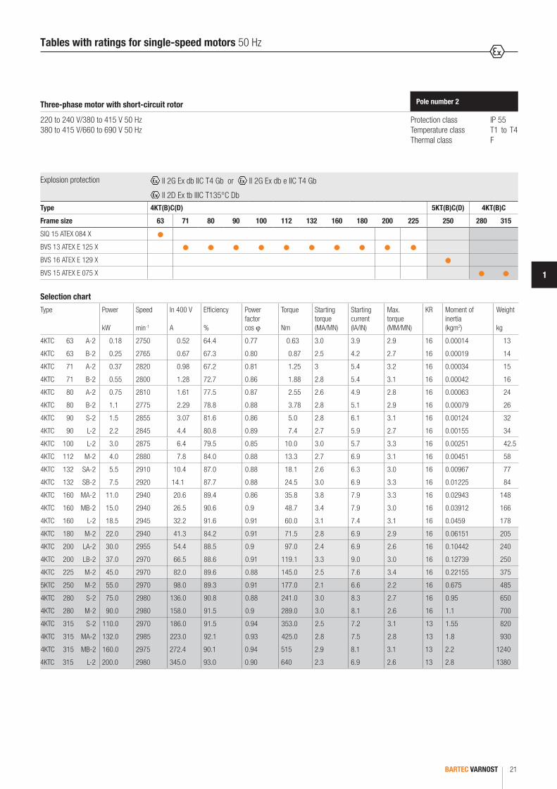
Selection chart
Type Power
kW
Speed
min-1
In 400 V
A
Efficiency
%
Powerfactorcos ϕ
Torque
Nm
Startingtorque (MA/MN)
Starting current (IA/IN)
Max.torque (MM/MN)
KR Moment of inertia (kgm2)
Weight
kg
4KTC 63 A-2 0.18 2750 0.52 64.4 0.77 0.63 3.0 3.9 2.9 16 0.00014 13
4KTC 63 B-2 0.25 2765 0.67 67.3 0.80 0.87 2.5 4.2 2.7 16 0.00019 14
4KTC 71 A-2 0.37 2820 0.98 67.2 0.81 1.25 3 5.4 3.2 16 0.00034 15
4KTC 71 B-2 0.55 2800 1.28 72.7 0.86 1.88 2.8 5.4 3.1 16 0.00042 16
4KTC 80 A-2 0.75 2810 1.61 77.5 0.87 2.55 2.6 4.9 2.8 16 0.00063 24
4KTC 80 B-2 1.1 2775 2.29 78.8 0.88 3.78 2.8 5.1 2.9 16 0.00079 26
4KTC 90 S-2 1.5 2855 3.07 81.6 0.86 5.0 2.8 6.1 3.1 16 0.00124 32
4KTC 90 L-2 2.2 2845 4.4 80.8 0.89 7.4 2.7 5.9 2.7 16 0.00155 34
4KTC 100 L-2 3.0 2875 6.4 79.5 0.85 10.0 3.0 5.7 3.3 16 0.00251 42.5
4KTC 112 M-2 4.0 2880 7.8 84.0 0.88 13.3 2.7 6.9 3.1 16 0.00451 58
4KTC 132 SA-2 5.5 2910 10.4 87.0 0.88 18.1 2.6 6.3 3.0 16 0.00967 77
4KTC 132 SB-2 7.5 2920 14.1 87.7 0.88 24.5 3.0 6.9 3.3 16 0.01225 84
4KTC 160 MA-2 11.0 2940 20.6 89.4 0.86 35.8 3.8 7.9 3.3 16 0.02943 148
4KTC 160 MB-2 15.0 2940 26.5 90.6 0.9 48.7 3.4 7.9 3.0 16 0.03912 166
4KTC 160 L-2 18.5 2945 32.2 91.6 0.91 60.0 3.1 7.4 3.1 16 0.0459 178
4KTC 180 M-2 22.0 2940 41.3 84.2 0.91 71.5 2.8 6.9 2.9 16 0.06151 205
4KTC 200 LA-2 30.0 2955 54.4 88.5 0.9 97.0 2.4 6.9 2.6 16 0.10442 240
4KTC 200 LB-2 37.0 2970 66.5 88.6 0.91 119.1 3.3 9.0 3.0 16 0.12739 250
4KTC 225 M-2 45.0 2970 82.0 89.6 0.88 145.0 2.5 7.6 3.4 16 0.22155 375
5KTC 250 M-2 55.0 2970 98.0 89.3 0.91 177.0 2.1 6.6 2.2 16 0.675 485
4KTC 280 S-2 75.0 2980 136.0 90.8 0.88 241.0 3.0 8.3 2.7 16 0.95 650
4KTC 280 M-2 90.0 2980 158.0 91.5 0.9 289.0 3.0 8.1 2.6 16 1.1 700
4KTC 315 S-2 110.0 2970 186.0 91.5 0.94 353.0 2.5 7.2 3.1 13 1.55 820
4KTC 315 MA-2 132.0 2985 223.0 92.1 0.93 425.0 2.8 7.5 2.8 13 1.8 930
4KTC 315 MB-2 160.0 2975 272.4 90.1 0.94 515 2.9 8.1 3.1 13 2.2 1240
4KTC 315 L-2 200.0 2980 345.0 93.0 0.90 640 2.3 6.9 2.6 13 2.8 1380
Three-phase motor with short-circuit rotor Pole number 2
Protection class IP 55Temperature class T1 to T4 Thermal class F
220 to 240 V/380 to 415 V 50 Hz 380 to 415 V/660 to 690 V 50 Hz
Tables with ratings for single-speed motors 50 Hz
Explosion protection II 2G Ex db IIC T4 Gb or II 2G Ex db e IIC T4 Gb
II 2D Ex tb IIIC T135°C DbType 4KT(B)C(D) 5KT(B)C(D) 4KT(B)C
Frame size 63 71 80 90 100 112 132 160 180 200 225 250 280 315
SIQ 15 ATEX 084 X
BVS 13 ATEX E 125 X
BVS 16 ATEX E 129 X
BVS 15 ATEX E 075 X
BARTEC VARNOST22
Protection class IP 55Temperature class T1 to T4Thermal class F
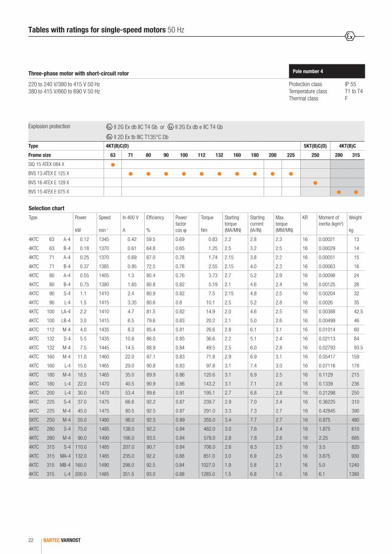
Pole number 4Three-phase motor with short-circuit rotor
220 to 240 V/380 to 415 V 50 Hz 380 to 415 V/660 to 690 V 50 Hz
Selection chart
Type Power
kW
Speed
min-1
In 400 V
A
Efficiency
%
Powerfactorcos ϕ
Torque
Nm
Startingtorque (MA/MN)
Starting current (IA/IN)
Max.torque (MM/MN)
KR Moment of inertia (kgm2)
Weight
kg
4KTC 63 A-4 0.12 1345 0.42 59.5 0.69 0.83 2.2 2.8 2.3 16 0.00021 13
4KTC 63 B-4 0.18 1370 0.61 64.8 0.65 1.25 2.5 3.2 2.5 16 0.00029 14
4KTC 71 A-4 0.25 1370 0.69 67.0 0.78 1.74 2.15 3.8 2.2 16 0.00051 15
4KTC 71 B-4 0.37 1385 0.95 72.5 0.78 2.55 2.15 4.0 2.3 16 0.00063 16
4KTC 80 A-4 0.55 1405 1.3 80.4 0.76 3.73 2.7 5.2 2.9 16 0.00098 24
4KTC 80 B-4 0.75 1380 1.65 80.8 0.82 5.19 2.1 4.6 2.4 16 0.00125 26
4KTC 90 S-4 1.1 1410 2.4 80.9 0.82 7.5 2.15 4.8 2.5 16 0.00204 32
4KTC 90 L-4 1.5 1415 3.35 80.6 0.8 10.1 2.5 5.2 2.8 16 0.0026 35
4KTC 100 LA-4 2.2 1410 4.7 81.5 0.82 14.9 2.0 4.6 2.5 16 0.00388 42.5
4KTC 100 LB-4 3.0 1415 6.5 79.6 0.83 20.2 2.1 5.0 2.6 16 0.00499 46
4KTC 112 M-4 4.0 1435 8.3 85.4 0.81 26.6 2.8 6.1 3.1 16 0.01014 60
4KTC 132 S-4 5.5 1435 10.8 86.0 0.85 36.6 2.2 5.1 2.4 16 0.02113 84
4KTC 132 M-4 7.5 1445 14.5 88.9 0.84 49.5 2.5 6.0 2.8 16 0.02793 93.5
4KTC 160 M-4 11.0 1460 22.0 87.1 0.83 71.8 2.9 6.9 3.1 16 0.05417 159
4KTC 160 L-4 15.0 1465 29.0 90.8 0.83 97.8 3.1 7.4 3.0 16 0.07116 178
4KTC 180 M-4 18.5 1465 35.0 89.9 0.86 120.6 3.1 6.9 2.5 16 0.1129 215
4KTC 180 L-4 22.0 1470 40.5 90.9 0.86 143.2 3.1 7.1 2.6 16 0.1339 236
4KTC 200 L-4 30.0 1470 53.4 89.6 0.91 195.1 2.7 6.8 2.8 16 0.21298 250
4KTC 225 S-4 37.0 1475 66.6 92.2 0.87 239.7 2.9 7.0 2.4 16 0.36225 310
4KTC 225 M-4 45.0 1475 80.5 92.5 0.87 291.0 3.3 7.3 2.7 16 0.42845 390
5KTC 250 M-4 55.0 1480 98.0 92.5 0.89 355.0 3.4 7.7 2.7 16 0.875 480
4KTC 280 S-4 75.0 1485 138.0 92.2 0.84 482.0 3.0 7.6 2.4 16 1.875 610
4KTC 280 M-4 90.0 1490 166.0 93.5 0.84 578.0 2.8 7.8 2.6 16 2.25 685
4KTC 315 S-4 110.0 1485 207.0 90.7 0.84 706.0 2.6 6.3 2.5 16 3.5 820
4KTC 315 MA-4 132.0 1485 235.0 92.2 0.88 851.0 3.0 6.9 2.5 16 3.875 930
4KTC 315 MB-4 160.0 1490 298.0 92.5 0.84 1027.0 1.9 5.8 2.1 16 5.0 1240
4KTC 315 L-4 200.0 1485 351.5 93.0 0.88 1285.0 1.5 6.8 1.6 16 6.1 1380
Tables with ratings for single-speed motors 50 Hz
Explosion protection II 2G Ex db IIC T4 Gb or II 2G Ex db e IIC T4 Gb
II 2D Ex tb IIIC T135°C DbType 4KT(B)C(D) 5KT(B)C(D) 4KT(B)C
Frame size 63 71 80 90 100 112 132 160 180 200 225 250 280 315
SIQ 15 ATEX 084 X
BVS 13 ATEX E 125 X
BVS 16 ATEX E 129 X
BVS 15 ATEX E 075 X

BARTEC VARNOST 23
1
Protection class IP 55Temperature class T1 to T4Thermal class F
Pole number 6Three-phase motor with short-circuit rotor
220 to 240 V/380 to 415 V 50 Hz 380 to 415 V/660 to 690 V 50 Hz
Selection chart
Type Power
kW
Speed
min-1
In 400 V
A
Efficiency
%
Powerfactorcos ϕ
Torque
Nm
Startingtorque (MA/MN)
Starting current (IA/IN)
Max.torque (MM/MN)
KR Moment of inertia (kgm2)
Weight
kg
4KTC 63 A-6 0.09 895 0.43 51.0 0.61 0.96 2.2 2.3 2.3 16 0.00031 13
4KTC 63 B-6 0.12 900 0.52 55.0 0.60 1.27 2.5 2.5 2.5 16 0.00042 14
4KTC 71 A-6 0.18 930 0.67 60.0 0.65 1.86 2.1 3.1 2.3 16 0.00081 15
4KTC 71 B-6 0.25 940 0.85 64.0 0.67 2.56 2.2 3.7 2.5 16 0.00101 16
4KTC 80 A-6 0.37 925 1.1 67.0 0.72 3.83 2.3 3.6 2.5 16 0.00191 25
4KTC 80 B-6 0.55 915 1.5 72.0 0.74 5.7 2.35 4.1 2.5 16 0.00239 26.5
4KTC 90 S-6 0.75 915 2.1 70.0 0.74 7.8 1.8 3.7 2.1 16 0.00323 32
4KTC 90 L-6 1.1 915 3.0 73.0 0.73 11.5 2.1 4.1 2.3 16 0.00419 35
4KTC 100 L-6 1.5 930 3.7 76.0 0.77 15.4 2.2 4.7 2.3 16 0.00657 46
4KTC 112 M-6 2.2 960 5.0 82.0 0.78 21.9 2.6 6.1 2.7 16 0.0158 60
4KTC 132 S-6 3.0 975 6.6 83.5 0.79 29.4 2.3 6.3 2.5 16 0.02722 84
4KTC 132 MA-6 4.0 960 8.8 83.0 0.8 39.9 2.4 6.3 2.9 16 0.03229 88
4KTC 132 MB-6 5.5 955 11.8 83.5 0.81 55.1 2.3 6.1 2.9 16 0.03838 95
4KTC 160 M-6 7.5 970 15.8 86.0 0.8 74.2 2.7 6.7 2.4 16 0.08121 161
4KTC 160 L-6 11.0 965 23.5 88.5 0.77 109.0 2.2 6.0 2.3 16 0.10916 182
4KTC 180 L-6 15.0 965 31.0 89.5 0.78 148.0 1.9 5.2 2.3 16 0.227 236
4KTC 200 LA-6 18.5 965 36.0 91.0 0.81 183.0 1.9 6.0 2.4 16 0.24369 240
4KTC 200 LB-6 22.0 965 43.0 91.5 0.81 218.6 1.9 6.0 2.4 16 0.27888 250
4KTC 225 M-6 30.0 975 56.0 92.5 0.83 293.0 1.8 5.8 2.5 16 0.66117 390
5KTC 250 M-6 37.0 985 69.0 93.5 0.83 359.0 2.8 6.0 2.6 16 1.125 480
4KTC 280 S-6 45.0 985 82.0 94.5 0.84 437.0 2.5 6.3 2.7 16 2.3 610
4KTC 280 M-6 55.0 985 101.0 94.5 0.84 534.0 2.4 6.0 2.8 16 2.625 685
4KTC 315 S-6 75.0 980 140.0 95.0 0.82 732.0 2.5 5.9 2.8 16 4.625 820
4KTC 315 MA-6 90.0 985 163.0 95.5 0.84 874.0 2.1 5.1 2.9 16 5.25 930
4KTC 315 MB-6 110.0 990 198.0 91.5 0.88 1060.0 2.5 6.5 2.4 16 6.0 1240
4KTC 315 L-6 132.0 990 238.0 90.5 0.88 1275.0 2.6 6.8 2.4 16 7.3 1380
Tables with ratings for single-speed motors 50 Hz
Explosion protection II 2G Ex db IIC T4 Gb or II 2G Ex db e IIC T4 Gb
II 2D Ex tb IIIC T135°C DbType 4KT(B)C(D) 5KT(B)C(D) 4KT(B)C
Frame size 63 71 80 90 100 112 132 160 180 200 225 250 280 315
SIQ 15 ATEX 084 X
BVS 13 ATEX E 125 X
BVS 16 ATEX E 129 X
BVS 15 ATEX E 075 X

BARTEC VARNOST24
Protection class IP 55Temperature class T1 to T4Thermal class F
Pole number 8Three-phase motor with short-circuit rotor
220 to 240 V/380 to 415 V 50 Hz 380 to 415 V/660 to 690 V 50 Hz
Selection chart
Type Power
kW
Speed
min-1
In 400 V
A
Efficiency
%
Powerfactorcos ϕ
Torque
Nm
Startingtorque (MA/MN)
Starting current (IA/IN)
Max.torque (MM/MN)
KR Moment of inertia (kgm2)
Weight
kg
4KTC 63 B-8 0.06 600 0.39 31.0 0.73 0.80 1.4 1.7 1.4 16 0.0002 14
4KTC 71 A-8 0.09 680 0.67 38.0 0.51 1.26 2.0 2.0 2.1 16 0.00081 15
4KTC 71 B-8 0.12 655 0.54 45.0 0.71 1.75 1.8 2.4 2.1 16 0.00101 16
4KTC 80 A-8 0.18 680 0.66 61.0 0.65 2.53 2.1 2.9 2.2 16 0.00191 25
4KTC 80 B-8 0.25 680 0.92 58.0 0.68 3.52 2.1 3.1 2.3 16 0.00239 26.5
4KTC 90 S-8 0.37 685 1.25 66.0 0.65 5.2 1.7 3.0 2.0 16 0.00323 32
4KTC 90 L-8 0.55 685 1.75 69.0 0.66 7.7 1.75 3.1 2.1 16 0.00419 35
4KTC 100 LA-8 0.75 690 2.3 69.0 0.69 10.4 1.8 3.5 2.1 16 0.00657 42.5
4KTC 100 LB-8 1.1 695 3.25 70.0 0.7 15.0 1.9 3.8 2.2 16 0.00857 46
4KTC 112 M-8 1.5 710 4.15 78.0 0.67 20.2 2.0 4.3 2.5 16 0.0158 60
4KTC 132 S-8 2.2 710 5.5 79.0 0.74 29.6 1.9 4.3 2.2 16 0.02606 79
4KTC 132 M-8 3.0 710 7.2 80.0 0.76 40.4 2.1 4.8 2.3 16 0.03446 85
4KTC 160 MA-8 4.0 720 10.0 82.6 0.71 53.1 1.8 4.8 2.3 16 0.0688 146
4KTC 160 MB-8 5.5 715 13.4 84.0 0.71 73.6 1.8 4.8 2.1 16 0.08939 160
4KTC 160 L-8 7.5 725 16.7 86.5 0.75 98.8 2.3 5.8 2.1 16 0.12027 182
4KTC 180 L-8 11.0 715 25.0 86.7 0.74 147.0 1.8 4.2 2.5 16 0.227 236
4KTC 200 L-8 15.0 720 29.0 91.0 0.82 196.0 2.1 4.5 2.5 16 0.37827 250
4KTC 225 S-8 18.5 710 37.0 91.0 0.79 249.0 2.1 4.6 2.6 16 0.57008 310
4KTC 225 M-8 22.0 715 45.0 91.5 0.77 294.0 2.1 4.6 2.6 16 0.67806 390
5KTC 250 M-8 30.0 730 59.0 92.8 0.79 398.0 1.7 5.4 2.4 16 1.175 480
4KTC 280 S-8 37.0 730 74.0 93.0 0.78 485.0 1.9 6.0 2.3 16 2.3 610
4KTC 280 M-8 45.0 735 90.0 93.5 0.78 586.0 1.9 6.4 2.7 16 2.625 685
4KTC 315 S-8 55.0 735 104.0 94.5 0.81 716.0 2.2 6.2 2.3 16 4.625 820
4KTC 315 MA-8 75.0 740 140.0 94.5 0.82 969.0 1.8 6.3 2.1 16 5.25 930
4KTC 315 MB-8 90.0 740 173.0 91.1 0.83 1160.0 2.5 6.7 2.5 16 6.0 1240
4KTC 315 L-8 110.0 740 213.0 90.0 0.83 1420.0 2.6 6.9 2.5 16 7.3 1380
Tables with ratings for single-speed motors 50 Hz
Explosion protection II 2G Ex db IIC T4 Gb or II 2G Ex db e IIC T4 Gb
II 2D Ex tb IIIC T135°C DbType 4KT(B)C(D) 5KT(B)C(D) 4KT(B)C
Frame size 63 71 80 90 100 112 132 160 180 200 225 250 280 315
SIQ 15 ATEX 084 X
BVS 13 ATEX E 125 X
BVS 16 ATEX E 129 X
BVS 15 ATEX E 075 X
BARTEC VARNOST 25
1
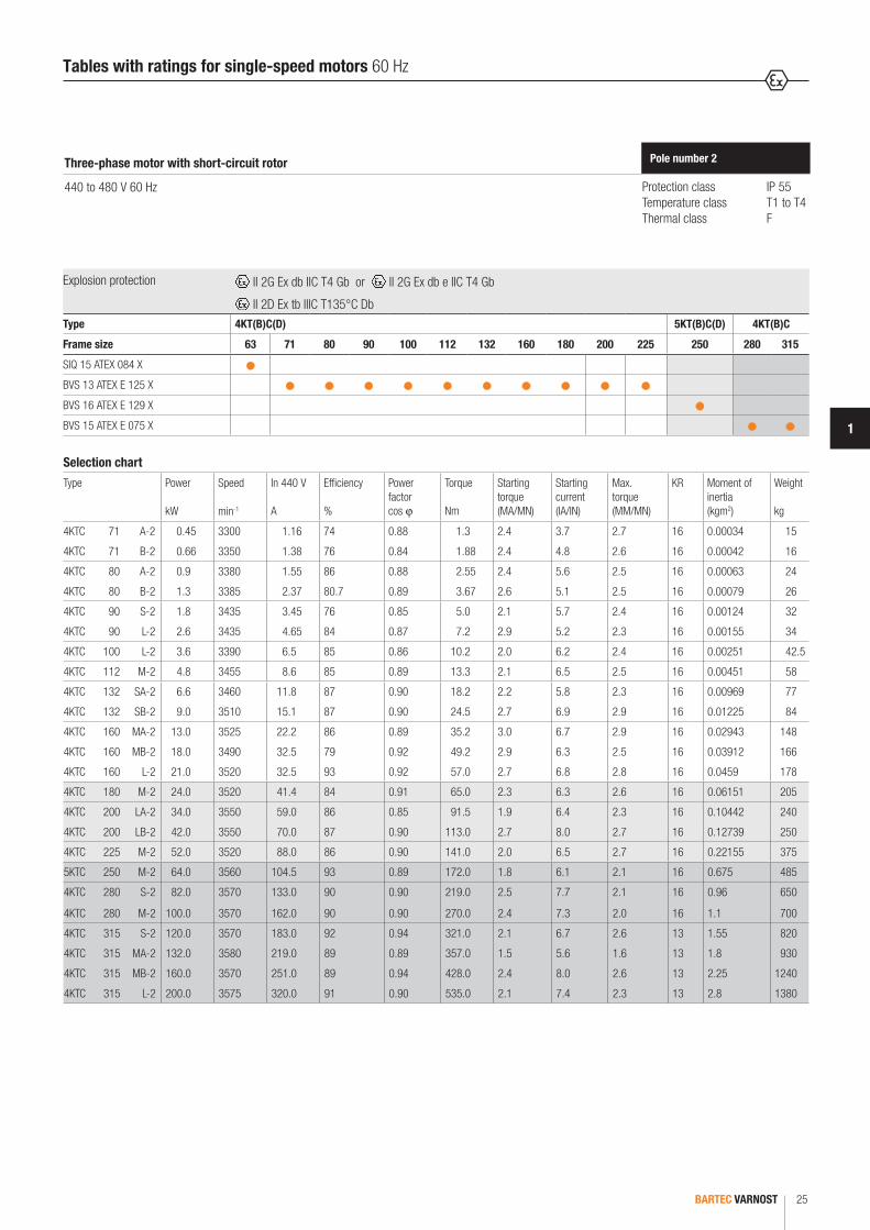
Protection class IP 55Temperature class T1 to T4Thermal class F
Pole number 2Three-phase motor with short-circuit rotor
440 to 480 V 60 Hz
Selection chart
Type Power
kW
Speed
min-1
In 440 V
A
Efficiency
%
Powerfactorcos ϕ
Torque
Nm
Startingtorque (MA/MN)
Starting current (IA/IN)
Max.torque (MM/MN)
KR Moment of inertia (kgm2)
Weight
kg
4KTC 71 A-2 0.45 3300 1.16 74 0.88 1.3 2.4 3.7 2.7 16 0.00034 15
4KTC 71 B-2 0.66 3350 1.38 76 0.84 1.88 2.4 4.8 2.6 16 0.00042 16
4KTC 80 A-2 0.9 3380 1.55 86 0.88 2.55 2.4 5.6 2.5 16 0.00063 24
4KTC 80 B-2 1.3 3385 2.37 80.7 0.89 3.67 2.6 5.1 2.5 16 0.00079 26
4KTC 90 S-2 1.8 3435 3.45 76 0.85 5.0 2.1 5.7 2.4 16 0.00124 32
4KTC 90 L-2 2.6 3435 4.65 84 0.87 7.2 2.9 5.2 2.3 16 0.00155 34
4KTC 100 L-2 3.6 3390 6.5 85 0.86 10.2 2.0 6.2 2.4 16 0.00251 42.5
4KTC 112 M-2 4.8 3455 8.6 85 0.89 13.3 2.1 6.5 2.5 16 0.00451 58
4KTC 132 SA-2 6.6 3460 11.8 87 0.90 18.2 2.2 5.8 2.3 16 0.00969 77
4KTC 132 SB-2 9.0 3510 15.1 87 0.90 24.5 2.7 6.9 2.9 16 0.01225 84
4KTC 160 MA-2 13.0 3525 22.2 86 0.89 35.2 3.0 6.7 2.9 16 0.02943 148
4KTC 160 MB-2 18.0 3490 32.5 79 0.92 49.2 2.9 6.3 2.5 16 0.03912 166
4KTC 160 L-2 21.0 3520 32.5 93 0.92 57.0 2.7 6.8 2.8 16 0.0459 178
4KTC 180 M-2 24.0 3520 41.4 84 0.91 65.0 2.3 6.3 2.6 16 0.06151 205
4KTC 200 LA-2 34.0 3550 59.0 86 0.85 91.5 1.9 6.4 2.3 16 0.10442 240
4KTC 200 LB-2 42.0 3550 70.0 87 0.90 113.0 2.7 8.0 2.7 16 0.12739 250
4KTC 225 M-2 52.0 3520 88.0 86 0.90 141.0 2.0 6.5 2.7 16 0.22155 375
5KTC 250 M-2 64.0 3560 104.5 93 0.89 172.0 1.8 6.1 2.1 16 0.675 485
4KTC 280 S-2 82.0 3570 133.0 90 0.90 219.0 2.5 7.7 2.1 16 0.96 650
4KTC 280 M-2 100.0 3570 162.0 90 0.90 270.0 2.4 7.3 2.0 16 1.1 700
4KTC 315 S-2 120.0 3570 183.0 92 0.94 321.0 2.1 6.7 2.6 13 1.55 820
4KTC 315 MA-2 132.0 3580 219.0 89 0.89 357.0 1.5 5.6 1.6 13 1.8 930
4KTC 315 MB-2 160.0 3570 251.0 89 0.94 428.0 2.4 8.0 2.6 13 2.25 1240
4KTC 315 L-2 200.0 3575 320.0 91 0.90 535.0 2.1 7.4 2.3 13 2.8 1380
Tables with ratings for single-speed motors 60 Hz
Explosion protection II 2G Ex db IIC T4 Gb or II 2G Ex db e IIC T4 Gb
II 2D Ex tb IIIC T135°C DbType 4KT(B)C(D) 5KT(B)C(D) 4KT(B)C
Frame size 63 71 80 90 100 112 132 160 180 200 225 250 280 315
SIQ 15 ATEX 084 X
BVS 13 ATEX E 125 X
BVS 16 ATEX E 129 X
BVS 15 ATEX E 075 X

BARTEC VARNOST26
Protection class IP 55Temperature class T1 to T4Thermal class F
Pole number 4Three-phase motor with short-circuit rotor
440 to 480 V 60 Hz
Selection chart
Type Power
kW
Speed
min-1
In 440 V
A
Efficiency
%
Powerfactorcos ϕ
Torque
Nm
Startingtorque (MA/MN)
Starting current (IA/IN)
Max.torque (MM/MN)
KR Moment of inertia (kgm2)
Weight
kg
4KTC 71 A-4 0.30 1640 0.80 60 0.78 1.75 1.8 3.0 1.9 16 0.00051 15
4KTC 71 B-4 0.45 1650 1.01 71 0.82 2.60 2.1 4.1 2.0 16 0.00063 16
4KTC 80 A-4 0.66 1640 1.52 75 0.83 3.84 1.9 4.1 2.0 16 0.00098 24
4KTC 80 B-4 0.90 1670 1.87 75 0.82 5.10 2.2 4.2 2.3 16 0.00125 26
4KTC 90 S-4 1.3 1675 2.47 82 0.85 7.40 1.9 5.2 2.1 16 0.00204 32
4KTC 90 L-4 1.8 1680 3.40 82 0.85 10.2 2.3 5.8 2.3 16 0.0026 35
4KTC 100 LA-4 2.6 1675 5.1 74 0.85 14.8 1.7 4.2 1.7 16 0.00388 42.5
4KTC 100 LB-4 3.6 1680 6.8 80 0.86 20.5 1.8 4.7 2.2 16 0.00499 46
4KTC 112 M-4 4.8 1730 8.6 87 0.85 26.5 2.3 6.1 2.8 16 0.01014 60
4KTC 132 S-4 6.6 1700 12.3 87 0.87 37.0 1.9 4.8 1.9 16 0.02113 84
4KTC 132 M-4 9.0 1730 15.6 88 0.86 49.6 2.3 4.6 2.3 16 0.02793 93.5
4KTC 160 M-4 13.0 1730 23.4 88 0.86 71.8 2.3 5.0 2.4 16 0.05417 159
4KTC 160 L-4 17.5 1755 29.3 88 0.86 94.2 2.3 6.3 2.5 16 0.07116 178
4KTC 180 M-4 21.0 1740 36.3 88 0.87 115.0 2.8 5.8 2.2 16 0.1129 215
4KTC 180 L-4 26.0 1770 42.7 91 0.85 140.0 2.7 6.5 2.2 16 0.1339 236
4KTC 200 L-4 34.0 1760 54.0 92 0.92 185.0 2.4 6.0 2.5 16 0.21298 250
4KTC 225 S-4 44.0 1770 71.8 91 0.88 237.0 2.1 5.8 1.9 16 0.36225 310
4KTC 225 M-4 52.0 1775 84.4 93 0.87 280.0 2.4 5.9 2.2 16 0.42845 390
5KTC 250 M-4 64.0 1770 104.0 90 0.9 345.0 3.0 7.6 2.2 16 0.875 480
4KTC 280 S-4 87.0 1780 144.0 91 0.86 467.0 2.3 5.5 1.8 16 1.875 610
4KTC 280 M-4 90.0 1790 148.0 93 0.85 481.0 2.5 8.6 2.3 16 2.25 685
4KTC 315 S-4 110.0 1790 186.0 89 0.87 588.0 2.4 6.7 2.1 16 3.9 820
4KTC 315 MA-4 132.0 1790 214.0 92 0.89 714.0 2.7 6.4 2.3 16 3.875 930
4KTC 315 MB-4 170.0 1795 288.0 92 0.85 905.0 1.5 5.5 1.6 16 5.0 1240
4KTC 315 L-4 200.0 1785 324.0 93 0.87 1071.0 1.6 6.8 1.8 16 6.1 1380
Tables with ratings for single-speed motors 60 Hz
Explosion protection II 2G Ex db IIC T4 Gb or II 2G Ex db e IIC T4 Gb
II 2D Ex tb IIIC T135°C DbType 4KT(B)C(D) 5KT(B)C(D) 4KT(B)C
Frame size 63 71 80 90 100 112 132 160 180 200 225 250 280 315
SIQ 15 ATEX 084 X
BVS 13 ATEX E 125 X
BVS 16 ATEX E 129 X
BVS 15 ATEX E 075 X

BARTEC VARNOST 27
1
Protection class IP 55Temperature class T1 to T4Thermal class F
Pole number 6Three-phase motor with short-circuit rotor
440 to 480 V 60 Hz
Selection chart
Type Power
kW
Speed
min-1
In 440 V
A
Efficiency
%
Powerfactorcos ϕ
Torque
Nm
Startingtorque (MA/MN)
Starting current (IA/IN)
Max.torque (MM/MN)
KR Moment of inertia (kgm2)
Weight
kg
4KTC 71 A-6 0.18 1115 0.67 60 0.65 1.55 2.1 3.1 2.3 16 0.00081 15
4KTC 71 B-6 0.25 1100 0.76 62 0.7 2.18 2.4 2.9 2.5 16 0.00101 16
4KTC 80 A-6 0.37 1100 1.06 62 0.74 3.23 2.1 3.5 2.5 16 0.00191 25
4KTC 80 B-6 0.55 1100 1.36 71 0.74 4.8 2.4 4.2 2.4 16 0.00239 26.5
4KTC 90 S-6 0.75 1090 1.94 69 0.72 6.6 1.8 3.6 2.0 16 0.0323 32
4KTC 90 L-6 1.1 1105 2.73 76 0.71 9.5 1.8 3.9 2.1 16 0.00419 35
4KTC 100 L-6 1.5 1110 3.35 76 0.76 12.8 2.2 4.8 2.2 16 0.00657 46
4KTC 112 M-6 2.2 1180 4.5 84 0.71 18 2.6 6.3 2.7 16 0.0158 60
4KTC 132 S-6 3.0 1170 6.0 82 0.79 24 2.3 6.4 2.5 16 0.02722 84
4KTC 132 MA-6 4.0 1150 8.1 80 0.8 33 2.4 6.2 2.9 16 0.03229 88
4KTC 132 MB-6 5.5 1150 10.8 81 0.82 45 2.3 6.2 3.0 16 0.03838 95
4KTC 160 M-6 7.5 1170 14.4 84 0.81 61 2.8 6.7 2.4 16 0.08121 161
4KTC 160 L-6 11.0 1165 20.0 86 0.83 90 2.3 7.2 3.6 16 0.10916 182
4KTC 180 L-6 15.0 1175 27.6 89 0.8 121 2.5 7.6 3.7 16 0.227 236
4KTC 200 LA-6 18.5 1175 32.6 89 0.83 150 1.4 5.6 2.3 13 0.24369 240
4KTC 200 LB-6 22.0 1180 39.3 91 0.81 178 2.2 8.0 3.3 16 0.27888 250
4KTC 225 M-6 30.0 1180 53.5 91 0.81 244 2.4 6.5 1.9 16 0.66117 390
5KTC 250 M-6 37.0 1185 69.0 92 0.75 298 1.9 4.1 1.7 13 1.125 480
4KTC 280 S-6 52.0 1185 94.0 91 0.8 418 1.9 4.4 1.9 16 2.3 610
4KTC 280 M-6 66.0 1170 119.0 90 0.82 540 1.7 3.7 1.6 16 2.625 685
4KTC 315 S-6 75.0 1180 140.0 95 0.82 610 2.5 5.9 2.8 16 4.625 820
4KTC 315 MA-6 90.0 1180 163.0 95 0.84 728 2.1 5.1 2.9 16 5.25 930
4KTC 315 MB-6 110.0 1190 175.0 94 0.88 884 2.1 6.1 2.2 16 6.0 1240
4KTC 315 L-6 132.0 1190 210.0 94 0.88 1160 2.0 6.3 2.1 16 7.3 1380
Tables with ratings for single-speed motors 60 Hz
Explosion protection II 2G Ex db IIC T4 Gb or II 2G Ex db e IIC T4 Gb
II 2D Ex tb IIIC T135°C DbType 4KT(B)C(D) 5KT(B)C(D) 4KT(B)C
Frame size 63 71 80 90 100 112 132 160 180 200 225 250 280 315
SIQ 15 ATEX 084 X
BVS 13 ATEX E 125 X
BVS 16 ATEX E 129 X
BVS 15 ATEX E 075 X

BARTEC VARNOST28
Protection class IP 55Temperature class T1 to T4Thermal class F
Pole number 8Three-phase motor with short-circuit rotor
440 to 480 V 60 Hz
Selection chart
Type Power
kW
Speed
min-1
In 440 V
A
Efficiency
%
Powerfactorcos ϕ
Torque
Nm
Startingtorque (MA/MN)
Starting current (IA/IN)
Max.torque (MM/MN)
KR Moment of inertia (kgm2)
Weight
kg
4KTC 71 A-8 0.09 820 0.42 45 0.62 1 2.2 2.5 2.1 16 0.00081 15
4KTC 71 B-8 0.12 780 0.49 45 0.71 1.47 1.8 2.4 2.0 16 0.00101 16
4KTC 80 A-8 0.18 825 0.62 58 0.63 2.1 2.1 2.9 2.1 16 0.00191 25
4KTC 80 B-8 0.25 825 0.84 58 0.67 2.9 2.0 3.1 2.3 16 0.00239 26.5
4KTC 90 S-8 0.37 820 1.17 64 0.62 4.3 1.6 2.9 1.9 16 0.00323 32
4KTC 90 L-8 0.55 825 1.6 72 0.61 6.4 1.7 3.2 2.0 16 0.00419 35
4KTC 100 LA-8 0.75 825 2.14 67 0.66 8.7 1.6 3.5 1.9 16 0.00657 42.5
4KTC 100 LB-8 1.1 845 3.1 71 0.62 12.4 2.0 4.0 2.3 16 0.00857 46
4KTC 112 M-8 1.5 855 3.8 77 0.67 16.8 2.0 4.3 2.5 16 0.0158 60
4KTC 132 S-8 2.2 845 5.0 75 0.76 24.6 1.8 4.3 2.2 16 0.02606 79
4KTC 132 M-8 3.0 850 6.6 79 0.73 33 2.2 4.9 2.3 16 0.03446 85
4KTC 160 MA-8 4.0 865 8.5 81 0.76 44 1.9 5.3 2.3 16 0.0688 146
4KTC 160 MB-8 5.5 865 10.9 84 0.78 60 1.9 5.0 2.1 16 0.08939 160
4KTC 160 L-8 7.5 875 15.3 85 0.76 82 2.3 6.2 2.1 16 0.12027 182
4KTC 180 L-8 11.0 870 20.7 88 0.8 121 2.0 5.8 2.5 16 0.227 236
4KTC 200 L-8 15.0 880 27.7 91 0.78 163 2.4 7.4 3.7 16 0.37827 250
4KTC 225 S-8 18.5 885 35.0 91 0.76 200 2.4 7.6 3.2 16 0.57008 310
4KTC 225 M-8 22.0 885 42.0 90 0.77 239 2.2 6.9 3.1 16 0.67806 390
5KTC 250 M-8 30.0 875 59.0 92 0.79 332 1.7 5.4 2.4 16 1.175 480
4KTC 280 S-8 37.0 875 74.0 93 0.78 404 1.9 6.0 2.3 16 2.3 610
4KTC 280 M-8 45.0 880 90.0 93 0.78 488 1.9 6.4 2.7 16 2.625 689
4KTC 315 S-8 55.0 880 104.0 94 0.81 597 2.2 6.2 2.3 16 4.625 820
4KTC 315 MA-8 75.0 890 140.0 94 0.82 969 1.8 6.3 2.1 16 5.25 930
4KTC 315 MB-8 90.0 885 153.0 93 0.83 973 1.9 6.4 2.0 16 6.0 1240
4KTC 315 L-8 110.0 885 189.0 93 0.82 1189 1.8 6.3 1.9 16 7.3 1380
Explosion protection II 2G Ex db IIC T4 Gb or II 2G Ex db e IIC T4 Gb
II 2D Ex tb IIIC T135°C DbType 4KT(B)C(D) 5KT(B)C(D) 4KT(B)C
Frame size 63 71 80 90 100 112 132 160 180 200 225 250 280 315
SIQ 15 ATEX 084 X
BVS 13 ATEX E 125 X
BVS 16 ATEX E 129 X
BVS 15 ATEX E 075 X
Tables with ratings for single-speed motors 60 Hz
BARTEC VARNOST 29
1
Protection class IP 55Temperature class T1 to T4Thermal class F
Pole number 4/2Three-phase motor with short-circuit rotor
D/YY 380 to 415 V 50 Hz
Selection chart
Type Power
kW
Speed
min-1
In 400 V
A
Starting current (IA/IN)
Max.torque (MM/MN)
Weight
kg
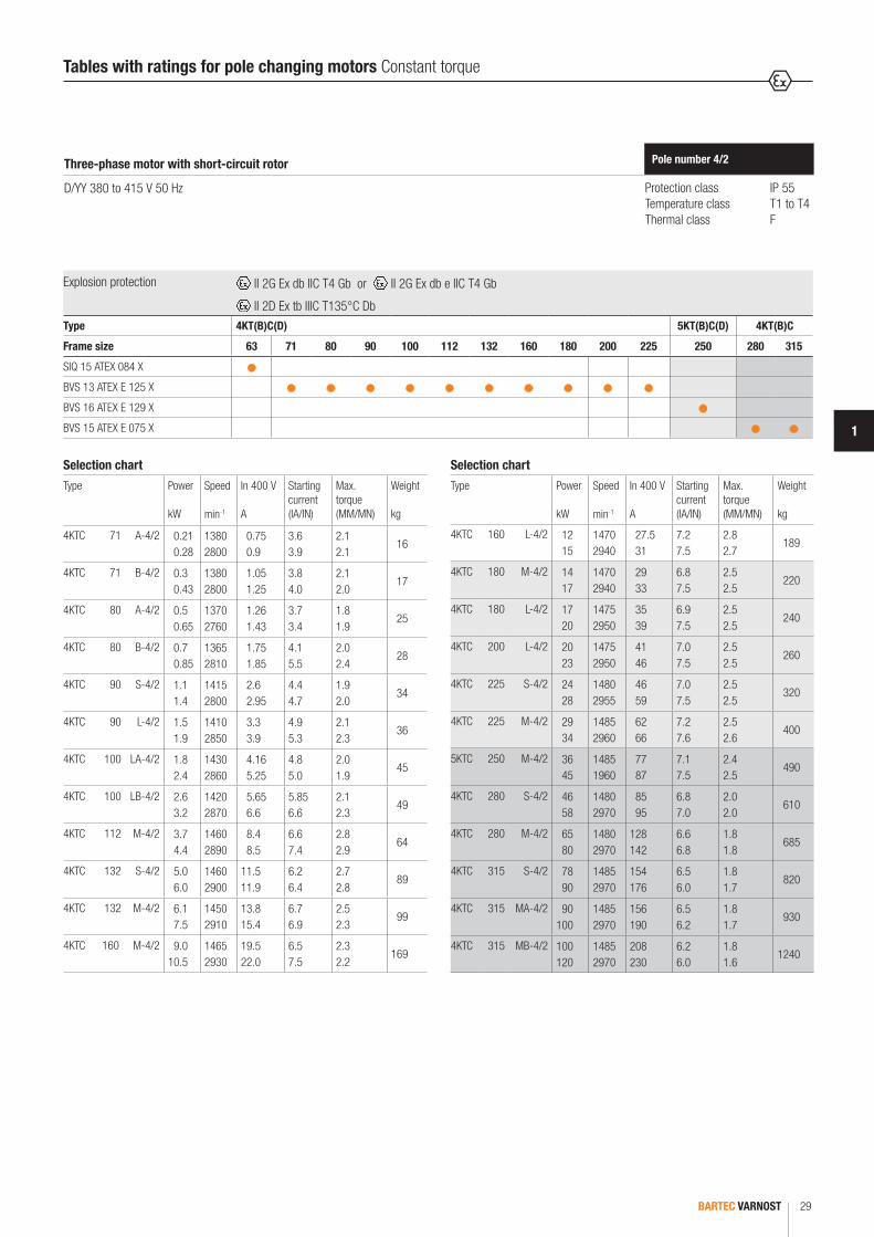
4KTC 71 A-4/2 0.21 0.28
1380 2800
0.75 0.9
3.6 3.9
2.1 2.1
16
4KTC 71 B-4/2 0.3 0.43
1380 2800
1.05 1.25
3.8 4.0
2.1 2.0
17
4KTC 80 A-4/2 0.5 0.65
1370 2760
1.26 1.43
3.7 3.4
1.8 1.9
25
4KTC 80 B-4/2 0.7 0.85
1365 2810
1.75 1.85
4.1 5.5
2.0 2.4
28
4KTC 90 S-4/2 1.1 1.4
1415 2800
2.6 2.95
4.4 4.7
1.9 2.0
34
4KTC 90 L-4/2 1.5 1.9
1410 2850
3.3 3.9
4.9 5.3
2.1 2.3
36
4KTC 100 LA-4/2 1.8 2.4
1430 2860
4.16 5.25
4.8 5.0
2.0 1.9
45
4KTC 100 LB-4/2 2.6 3.2
1420 2870
5.65 6.6
5.85 6.6
2.1 2.3
49
4KTC 112 M-4/2 3.7 4.4
1460 2890
8.4 8.5
6.6 7.4
2.8 2.9
64
4KTC 132 S-4/2 5.0 6.0
1460 2900
11.5 11.9
6.2 6.4
2.7 2.8
89
4KTC 132 M-4/2 6.1 7.5
1450 2910
13.8 15.4
6.7 6.9
2.5 2.3
99
4KTC 160 M-4/2 9.0 10.5
1465 2930
19.5 22.0
6.5 7.5
2.3 2.2
169
Selection chart
Type Power
kW
Speed
min-1
In 400 V
A
Starting current (IA/IN)
Max.torque (MM/MN)
Weight
kg
4KTC 160 L-4/2 12 15
1470 2940
27.5 31
7.2 7.5
2.8 2.7
189
4KTC 180 M-4/2 14 17
1470 2940
29 33
6.8 7.5
2.5 2.5
220
4KTC 180 L-4/2 17 20
1475 2950
35 39
6.9 7.5
2.5 2.5
240
4KTC 200 L-4/2 20 23
1475 2950
41 46
7.0 7.5
2.5 2.5
260
4KTC 225 S-4/2 24 28
1480 2955
46 59
7.0 7.5
2.5 2.5
320
4KTC 225 M-4/2 29 34
1485 2960
62 66
7.2 7.6
2.5 2.6
400
5KTC 250 M-4/2 36 45
1485 1960
77 87
7.1 7.5
2.4 2.5
490
4KTC 280 S-4/2 46 58
1480 2970
85 95
6.8 7.0
2.0 2.0
610
4KTC 280 M-4/2 65 80
1480 2970
128 142
6.6 6.8
1.8 1.8
685
4KTC 315 S-4/2 78 90
1485 2970
154 176
6.5 6.0
1.8 1.7
820
4KTC 315 MA-4/2 90 100
1485 2970
156 190
6.5 6.2
1.8 1.7
930
4KTC 315 MB-4/2 100 120
1485 2970
208 230
6.2 6.0
1.8 1.6
1240
Tables with ratings for pole changing motors Constant torque
Explosion protection II 2G Ex db IIC T4 Gb or II 2G Ex db e IIC T4 Gb
II 2D Ex tb IIIC T135°C DbType 4KT(B)C(D) 5KT(B)C(D) 4KT(B)C
Frame size 63 71 80 90 100 112 132 160 180 200 225 250 280 315
SIQ 15 ATEX 084 X
BVS 13 ATEX E 125 X
BVS 16 ATEX E 129 X
BVS 15 ATEX E 075 X

BARTEC VARNOST30
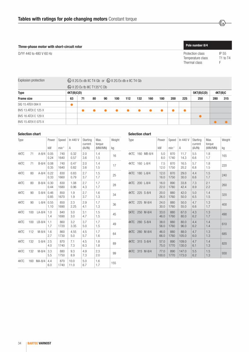
Tables with ratings for pole changing motors Constant torque
Protection class IP 55Temperature class T1 to T4Thermal class F
Pole number 8/4Three-phase motor with short-circuit rotor
D/YY 380 to 415 V 50 Hz
Selection chart
Type Power
kW
Speed
min-1
In 400 V
A
Starting current (IA/IN)
Max.torque (MM/MN)
Weight
kg
4KTC 71 A-8/4 0.048 0.22
620 1370
0.32 0.57
2.1 3.8
1.6 1.8
16
4KTC 71 B-8/4 0.07 0.32
620 1370
0.47 0.82
2.1 3.8
1.6 1.8
17
4KTC 80 A-8/4 0.2 0.3
690 1380
0.83 0.79
2.8 3.9
2.0 2.2
25
4KTC 80 B-8/4 0.27 0.4
690 1400
1.08 0.96
2.9 4.5
2.1 2.2
28
4KTC 90 S-8/4 0.42 0.8
705 1390
1.9 1.9
2.8 3.9
2.0 1.8
34
4KTC 90 L-8/4 0.5 1.0
710 1410
2.3 2.25
3.1 4.3
2.1 1.9
36
4KTC 100 LA-8/4 0.9 1.3
690 1380
3.05 3.0
3.2 4.2
2.1 2.1
45
4KTC 100 LB-8/4 1.0 1.6
720 1430
3.2 3.35
3.9 5.3
2.1 2.2
49
4KTC 112 M-8/4 1.5 2.5
710 1430
4.25 5.0
4.6 5.7
2.2 2.1
64
4KTC 132 S-8/4 2.3 3.6
720 1450
6.7 7.3
5.3 6.9
2.3 2.2
89
4KTC 132 M-8/4 3.0 5.0
720 1445
9.5 9.9
4.5 5.4
2.3 2.3
99
4KTC 160 MA-8/4 4.0 5.5
725 1460
10.5 10.8
5.2 7.0
1.8 1.8
155
Selection chart
Type Power
kW
Speed
min-1
In 400 V
A
Starting current (IA/IN)
Max.torque (MM/MN)
Weight
kg
4KTC 160 MB-8/4 4.6 7.3
725 1460
12.8 14.6
4.6 7.0
1.8 1.9
165
4KTC 160 L-8/4 6.8 11
725 1460
21 23
4.8 7.0
1.8 2.0
197
4KTC 180 L-8/4 11 15
725 1460
29 30
4.6 7.0
1.7 2.0
240
4KTC 200 L-8/4 15 20
730 1465
33 44
5.3 6.8
1.5 1.8
260
4KTC 225 S-8/4 18 24
730 1465
42 50
5.3 6.8
1.6 1.8
320
4KTC 225 M-8/4 22 28
730 1465
50 55
5.0 7.0
1.5 2.0
400
5KTC 250 M-8/4 30 42
730 1465
67 80
4.5 6.5
1.5 2.0
490
4KTC 280 S-8/4 35 51
735 1470
80 96
4.6 6.5
1.6 1.6
610
4KTC 280 M-8/4 42 60
735 1470
88 105
5.0 6.3
1.5 1.5
685
4KTC 315 S-8/4 52 68
740 1475
109 130
5.0 6.4
1.6 1.5
820
4KTC 315 M-8/4 70 90
740 1475
147 173
5.8 6.5
1.7 1.5
930
Explosion protection II 2G Ex db IIC T4 Gb or II 2G Ex db e IIC T4 Gb
II 2D Ex tb IIIC T135°C DbType 4KT(B)C(D) 5KT(B)C(D) 4KT(B)C
Frame size 63 71 80 90 100 112 132 160 180 200 225 250 280 315
SIQ 15 ATEX 084 X
BVS 13 ATEX E 125 X
BVS 16 ATEX E 129 X
BVS 15 ATEX E 075 X
BARTEC VARNOST 31
1
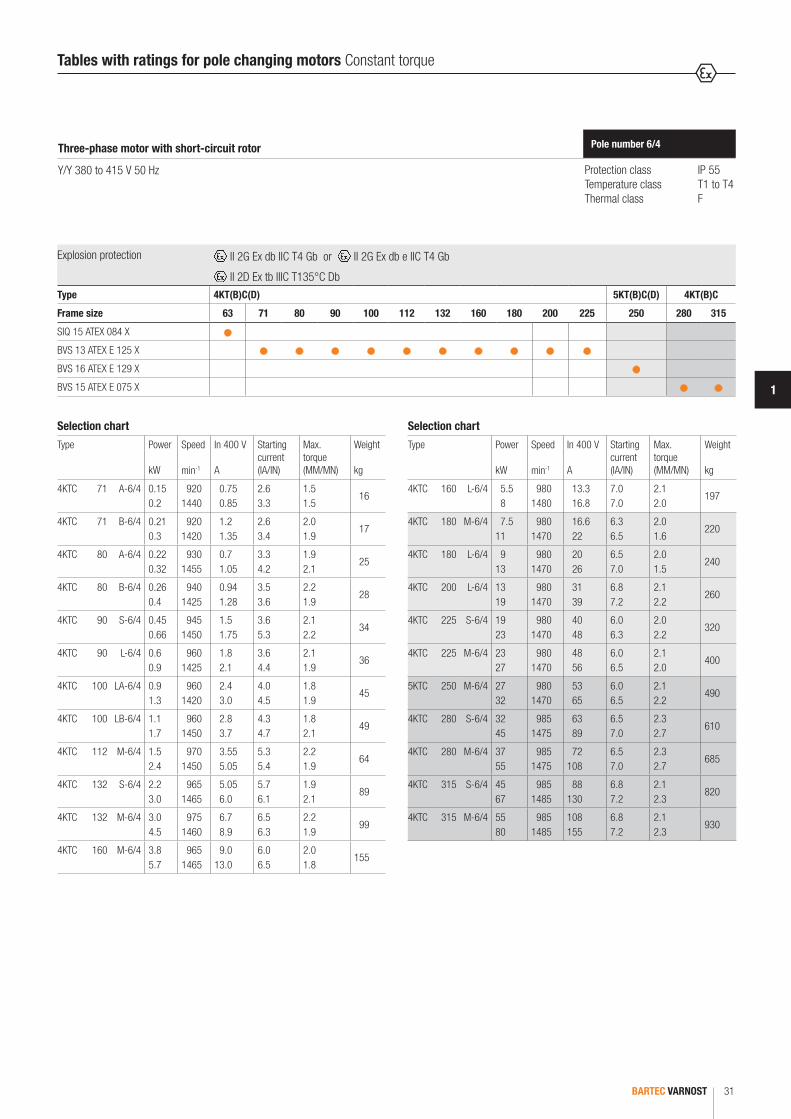
Tables with ratings for pole changing motors Constant torque
Protection class IP 55Temperature class T1 to T4Thermal class F
Pole number 6/4Three-phase motor with short-circuit rotor
Y/Y 380 to 415 V 50 Hz
Selection chart
Type Power
kW
Speed
min-1
In 400 V
A
Starting current (IA/IN)
Max.torque (MM/MN)
Weight
kg
4KTC 71 A-6/4 0.15 0.2
920 1440
0.75 0.85
2.6 3.3
1.5 1.5
16
4KTC 71 B-6/4 0.21 0.3
920 1420
1.2 1.35
2.6 3.4
2.0 1.9
17
4KTC 80 A-6/4 0.22 0.32
930 1455
0.7 1.05
3.3 4.2
1.9 2.1
25
4KTC 80 B-6/4 0.26 0.4
940 1425
0.94 1.28
3.5 3.6
2.2 1.9
28
4KTC 90 S-6/4 0.45 0.66
945 1450
1.5 1.75
3.6 5.3
2.1 2.2
34
4KTC 90 L-6/4 0.6 0.9
960 1425
1.8 2.1
3.6 4.4
2.1 1.9
36
4KTC 100 LA-6/4 0.9 1.3
960 1420
2.4 3.0
4.0 4.5
1.8 1.9
45
4KTC 100 LB-6/4 1.1 1.7
960 1450
2.8 3.7
4.3 4.7
1.8 2.1
49
4KTC 112 M-6/4 1.5 2.4
970 1450
3.55 5.05
5.3 5.4
2.2 1.9
64
4KTC 132 S-6/4 2.2 3.0
965 1465
5.05 6.0
5.7 6.1
1.9 2.1
89
4KTC 132 M-6/4 3.0 4.5
975 1460
6.7 8.9
6.5 6.3
2.2 1.9
99
4KTC 160 M-6/4 3.8 5.7
965 1465
9.0 13.0
6.0 6.5
2.0 1.8
155
Selection chart
Type Power
kW
Speed
min-1
In 400 V
A
Starting current (IA/IN)
Max.torque (MM/MN)
Weight
kg
4KTC 160 L-6/4 5.5 8
980 1480
13.3 16.8
7.0 7.0
2.1 2.0
197
4KTC 180 M-6/4 7.5 11
980 1470
16.6 22
6.3 6.5
2.0 1.6
220
4KTC 180 L-6/4 9 13
980 1470
20 26
6.5 7.0
2.0 1.5
240
4KTC 200 L-6/4 13 19
980 1470
31 39
6.8 7.2
2.1 2.2
260
4KTC 225 S-6/4 19 23
980 1470
40 48
6.0 6.3
2.0 2.2
320
4KTC 225 M-6/4 23 27
980 1470
48 56
6.0 6.5
2.1 2.0
400
5KTC 250 M-6/4 27 32
980 1470
53 65
6.0 6.5
2.1 2.2
490
4KTC 280 S-6/4 32 45
985 1475
63 89
6.5 7.0
2.3 2.7
610
4KTC 280 M-6/4 37 55
985 1475
72 108
6.5 7.0
2.3 2.7
685
4KTC 315 S-6/4 45 67
985 1485
88 130
6.8 7.2
2.1 2.3
820
4KTC 315 M-6/4 55 80
985 1485
108 155
6.8 7.2
2.1 2.3
930
Explosion protection II 2G Ex db IIC T4 Gb or II 2G Ex db e IIC T4 Gb
II 2D Ex tb IIIC T135°C DbType 4KT(B)C(D) 5KT(B)C(D) 4KT(B)C
Frame size 63 71 80 90 100 112 132 160 180 200 225 250 280 315
SIQ 15 ATEX 084 X
BVS 13 ATEX E 125 X
BVS 16 ATEX E 129 X
BVS 15 ATEX E 075 X

BARTEC VARNOST32
Tables with ratings for pole changing motors Constant torque
Protection class IP 55Temperature class T1 to T4Thermal class F
Pole number 8/6Three-phase motor with short-circuit rotor
Y/Y 380 to 415 V 50 Hz
Selection chart
Type Power
kW
Speed
min-1
In 400 V
A
Starting current (IA/IN)
Max.torque (MM/MN)
Weight
kg
4KTC 90 S-8/6 0.35 0.45
695 960
1.35 1.5
2.7 3.3
1.7 1.8
34
4KTC 90 L-8/6 0.45 0.6
695 960
1.68 2.07
2.7 3.5
1.8 2.0
36
4KTC 100 LA-8/6 0.6 0.8
715 970
2.05 2.15
2.9 4.1
1.6 1.8
45
4KTC 100 LB-8/6 0.75 0.9
710 970
2.4 2.5
3.1 4.7
1.6 2.0
49
4KTC 112 M-8/6 0.9 1.2
720 970
2.8 3.0
4.2 5.1
2.2 2.4
64
4KTC 132 S-8/6 1.5 2.0
725 975
5.05 5.5
4.8 6.2
2.5 2.4
89
4KTC 132 M-8/6 2.2 3.0
725 975
6.8 8.1
3.9 5.3
2.1 2.2
99
4KTC 160 M-8/6 3.5 5.0
725 975
8.8 12.0
5.5 6.4
2.3 2.1
155
4KTC 160 L-8/6 5.0 7.0
725 975
12.0 16.0
5.5 6.5
2.4 2.2
197
Selection chart
Type Power
kW
Speed
min-1
In 400 V
A
Starting current (IA/IN)
Max.torque (MM/MN)
Weight
kg
4KTC 180 L-8/6 7.0 9.5
725 980
18 24
5.5 6.2
2.0 1.8
240
4KTC 200 L-8/6 10 13
725 980
23 27
5.5 6.8
2.3 2.1
260
4KTC 225 S-8/6 13 16
725 975
29 36
5.3 6.2
1.7 1.4
320
4KTC 225 M-8/6 17 22
725 975
42 54
5.4 6.5
1.7 1.4
400
5KTC 250 M-8/6 22 30
730 985
51 65
5.8 6.5
1.9 1.6
490
4KTC 280 S-8/6 27 35
735 985
63 80
5.8 6.5
1.8 1.5
610
4KTC 280 M-8/6 33 41
735 985
74 90
6.0 6.7
1.8 1.5
685
4KTC 315 S-8/6 40 50
735 985
90 102
6.0 7.0
1.8 1.4
820
4KTC 315 M-8/6 48 62
735 985
103 125
6.0 7.0
1.8 1.4
930
Explosion protection II 2G Ex db IIC T4 Gb or II 2G Ex db e IIC T4 Gb
II 2D Ex tb IIIC T135°C DbType 4KT(B)C(D) 5KT(B)C(D) 4KT(B)C
Frame size 63 71 80 90 100 112 132 160 180 200 225 250 280 315
SIQ 15 ATEX 084 X
BVS 13 ATEX E 125 X
BVS 16 ATEX E 129 X
BVS 15 ATEX E 075 X

BARTEC VARNOST 33
1
Tables with ratings for pole changing motors Constant torque
Protection class IP 55Temperature class T1 to T4Thermal class F
Pole number 4/2Three-phase motor with short-circuit rotor
D/YY 440 to 480 V 60 Hz
Selection chart
Type Power
kW
Speed
min-1
In 440 V
A
Starting current (IA/IN)
Max.torque (MM/MN)
Weight
kg
4KTC 71 A-4/2 0.23 0.3
1660 3360
0.75 0.9
3.4 3.7
1.8 1.8
16
4KTC 71 B-4/2 0.33 0.45
1600 3360
1.05 1.25
3.6 3.8
1.8 1.7
17
4KTC 80 A-4/2 0.55 0.7
1640 3310
1.26 1.43
3.5 3.2
1.5 1.6
25
4KTC 80 B-4/2 0.75 0.9
1640 3380
1.75 1.85
3.9 5.2
1.6 1.9
28
4KTC 90 S-4/2 1.2 1.5
1700 3360
2.6 3.0
4.2 4.4
1.4 1.5
34
4KTC 90 L-4/2 1.6 2
1690 3420
3.3 3.9
4.6 5
1.6 1.8
36
4KTC 100 LA-4/2 2.0 2.6
1710 3410
4.1 5.2
4.5 3.9
1.5 1.5
45
4KTC 100 LB-4/2 2.8 3.5
1700 3440
5.65 6.6
4.8 5.5
1.6 1.7
49
4KTC 112 M-4/2 4.0 4.8
1750 3470
8.4 8.5
6.3 7.0
2.0 2.0
64
4KTC 132 S-4/2 5.5 6.5
1750 3480
11.5 11.9
5.9 6.0
2.3 2.4
89
4KTC 132 M-4/2 6.5 8.0
1750 3490
13.5 14.5
5.5 6.0
1.9 1.9
99
4KTC 160 M-4/2 10.0 11.0
1760 3520
19.5 22.0
6.2 7.1
2.0 2.2
1.9
Selection chart
Type Power
kW
Speed
min-1
In 440 V
A
Starting current (IA/IN)
Max.torque (MM/MN)
Weight
kg
4KTC 160 L-4/2 13 16
1760 3540
27.5 32.0
8.5 7.6
3.0 2.6
189
4KTC 180 M-4/2 15 18
1760 3530
29.0 33.0
6.5 7.1
2.1 2.1
220
4KTC 180 L-4/2 18 22
1770 3540
35.0 39.0
6.5 7.1
2.1 2.1
240
4KTC 200 L-4/2 22 25
1780 3550
37.0 43.0
8.0 8.0
2.6 2.1
260
4KTC 225 S-4/2 26 30
1780 3550
46.0 59.0
6.6 7.1
2.1 2.1
320
4KTC 225 M-4/2 31 37
1780 3550
62.0 66.0
6.8 7.2
2.1 2.2
400
5KTC 250 M-4/2 40 50
1780 3550
77.0 87.0
6.7 7.1
2.0 2.1
490
4KTC 280 S-4/2 50 63
1780 3560
85.0 95.0
6.5 6.6
1.7 1.7
610
4KTC 280 M-4/2 71 88
1780 3560
128.0 142.0
6.3 6.5
1.5 1.5
685
4KTC 315 S-4/2 85 98
1780 3560
154.0 176.0
6.2 5.7
1.5 1.5
820
4KTC 315 MA-4/2 98 110
1780 3560
156.0 190.0
6.2 5.9
1.5 1.5
930
4KTC 315 MB-4/2 110 130
1780 3560
208.0 230.0
5.9 5.7
1.5 1.4
1240
Explosion protection II 2G Ex db IIC T4 Gb or II 2G Ex db e IIC T4 Gb
II 2D Ex tb IIIC T135°C DbType 4KT(B)C(D) 5KT(B)C(D) 4KT(B)C
Frame size 63 71 80 90 100 112 132 160 180 200 225 250 280 315
SIQ 15 ATEX 084 X
BVS 13 ATEX E 125 X
BVS 16 ATEX E 129 X
BVS 15 ATEX E 075 X
BARTEC VARNOST34
Tables with ratings for pole changing motors Constant torque
Protection class IP 55Temperature class T1 to T4Thermal class F
Pole number 8/4Three-phase motor with short-circuit rotor
D/YY 440 to 480 V 60 Hz
Selection chart
Type Power
kW
Speed
min-1
In 440 V
A
Starting current (IA/IN)
Max.torque (MM/MN)
Weight
kg
4KTC 71 A-8/4 0.05 0.24
740 1640
0.32 0.57
2.0 3.6
1.4 1.5
16
4KTC 71 B-8/4 0.08 0.35
740 1640
0.47 0.82
2.0 3.6
1.4 1.5
17
4KTC 80 A-8/4 0.22 0.33
830 1660
0.83 0.79
2.7 3.7
1.5 1.7
25
4KTC 80 B-8/4 0.30 0.44
830 1680
1.08 0.96
2.7 4.3
1.7 1.7
28
4KTC 90 S-8/4 0.46 0.85
850 1670
1.9 1.9
2.7 3.7
1.6 1.3
34
4KTC 90 L-8/4 0.55 1.10
850 1690
2.3 2.25
2.9 4.1
1.7 1.3
36
4KTC 100 LA-8/4 1.0 1.4
840 1690
3.0 3.0
3.1 4.7
1.5 1.5
45
4KTC 100 LB-8/4 1.1 1.7
860 1720
3.2 3.35
3.7 5.0
1.7 1.5
49
4KTC 112 M-8/4 1.6 2.7
860 1730
4.55 5.0
4.5 5.7
1.7 1.6
64
4KTC 132 S-8/4 2.5 4.0
870 1740
7.1 7.3
4.5 6.3
1.8 1.8
89
4KTC 132 M-8/4 3.3 5.5
880 1750
9.3 8.9
4.9 7.3
2.3 2.0
99
4KTC 160 MA-8/4 4.4 6.0
870 1740
10.0 11.0
5.0 6.7
1.6 1.7
155
Selection chart
Type Power
kW
Speed
min-1
In 440 V
A
Starting current (IA/IN)
Max.torque (MM/MN)
Weight
kg
4KTC 160 MB-8/4 5.0 8.0
870 1740
11.7 14.3
5.5 6.6
1.8 1.7
165
4KTC 160 L-8/4 7.5 12.0
870 1750
16.5 20.2
5.7 6.8
1.8 1.5
220
4KTC 180 L-8/4 12.0 16.0
870 1750
29.0 30.0
4.4 6.6
1.5 1.7
240
4KTC 200 L-8/4 16.0 22.0
890 1780
33.8 42.4
7.3 8.9
2.1 2.2
260
4KTC 225 S-8/4 20.0 26.0
880 1760
42.0 50.0
5.0 6.5
1.4 1.5
320
4KTC 225 M-8/4 24.0 30.0
880 1760
50.0 55.0
4.7 6.6
1.3 1.7
400
5KTC 250 M-8/4 33.0 46.0
880 1760
67.0 80.0
4.3 6.2
1.3 1.7
490
4KTC 280 S-8/4 38.0 56.0
880 1760
80.0 96.0
4.4 6.2
1.4 1.4
610
4KTC 280 M-8/4 46.0 66.0
880 1760
88.0 105.0
4.7 6.0
1.3 1.3
685
4KTC 315 S-8/4 57.0 75.0
890 1770
109.0 130.0
4.7 6.1
1.4 1.3
820
4KTC 315 M-8/4 77.0 100.0
890 1770
147.0 173.0
5.5 6.2
1.5 1.3
930
Explosion protection II 2G Ex db IIC T4 Gb or II 2G Ex db e IIC T4 Gb
II 2D Ex tb IIIC T135°C DbType 4KT(B)C(D) 5KT(B)C(D) 4KT(B)C
Frame size 63 71 80 90 100 112 132 160 180 200 225 250 280 315
SIQ 15 ATEX 084 X
BVS 13 ATEX E 125 X
BVS 16 ATEX E 129 X
BVS 15 ATEX E 075 X

BARTEC VARNOST 35
1
Tables with ratings for pole changing motors Constant torque
Protection class IP 55Temperature class T1 to T4Thermal class F
Pole number 6/4Three-phase motor with short-circuit rotor
Y/Y 440 to 480 V 60 Hz
Selection chart
Type Power
kW
Speed
min-1
In 440 V
A
Starting current (IA/IN)
Max.torque (MM/MN)
Weight
kg
4KTC 71 A-6/4 0.16 0.22
1100 1730
0.75 0.85
2.5 3.1
1.4 1.3
16
4KTC 71 B-6/4 0.23 0.33
1100 1700
1.05 1.05
3.6 3.0
1.6 1.4
17
4KTC 80 A-6/4 0.24 0.35
1120 1750
0.7 1.07
3.1 4.0
1.5 1.6
25
4KTC 80 B-6/4 0.28 0.44
1140 1730
0.95 1.2
3.8 3.9
2.1 1.5
28
4KTC 90 S-6/4 0.5 0.7
1130 1740
1.5 1.75
3.4 5.0
1.8 1.9
34
4KTC 90 L-6/4 0.65 1.0
1150 1700
1.8 2.1
3.4 4.2
1.5 1.4
36
4KTC 100 LA-6/4 1.0 1.4
1150 1700
2.4 3.0
3.8 4.3
1.3 1.4
45
4KTC 100 LB-6/4 1.2 1.8
1150 1730
2.8 3.75
4.1 4.6
1.3 1.5
49
4KTC 112 M-6/4 1.6 2.6
1160 1740
3.55 5.05
5.0 5.2
1.6 1.5
64
4KTC 132 S-6/4 2.4 3.3
1160 1760
5.05 6.0
5.4 5.8
1.5 1.7
89
4KTC 132 M-6/4 3.3 5.0
1170 1750
6.7 8.9
6.2 6.0
1.7 1.5
99
4KTC 160 M-6/4 4.0 6.2
1180 1760
8.75 11.8
6.3 7.6
1.7 1.7
155
Selection chart
Type Power
kW
Speed
min-1
In 440 V
A
Starting current (IA/IN)
Max.torque (MM/MN)
Weight
kg
4KTC 160 L-6/4 6.0 8.8
1180 1770
12.3 15.5
6.7 8.5
1.7 2.0
197
4KTC 180 M-6/4 8.2 12.0
1180 1760
16.6 22.0
6.0 6.2
1.7 1.4
220
4KTC 180 L-6/4 10.0 14.0
1180 1760
20.0 26.0
6.2 6.6
1.7 1.3
240
4KTC 200 L-6/4 14.0 20.0
1180 1760
31.0 39.0
6.5 6.8
1.8 1.9
260
4KTC 225 S-6/4 20.0 25.0
1180 1760
40.0 48.0
5.7 6.0
1.7 1.9
320
4KTC 225 M-6/4 25.0 29.0
1180 1760
48.0 56.0
5.7 6.2
1.8 1.7
400
5KTC 250 M-6/4 29.0 35.0
1180 1760
53.0 65.0
5.7 6.2
1.8 1.9
490
4KTC 280 S-6/4 35.0 50.0
1180 1770
63.0 89.0
6.2 6.6
2.0 2.3
610
4KTC 280 M-6/4 40.0 60.0
1180 1770
72.0 108.0
6.2 6.6
2.0 2.3
685
4KTC 315 S-6/4 50.0 73.0
1180 1780
88.0 130.0
6.5 6.8
1.8 2.0
820
4KTC 315 M-6/4 60.0 88.0
1180 1780
108.0 155.0
6.5 6.8
1.8 2.0
930
Explosion protection II 2G Ex db IIC T4 Gb or II 2G Ex db e IIC T4 Gb
II 2D Ex tb IIIC T135°C DbType 4KT(B)C(D) 5KT(B)C(D) 4KT(B)C
Frame size 63 71 80 90 100 112 132 160 180 200 225 250 280 315
SIQ 15 ATEX 084 X
BVS 13 ATEX E 125 X
BVS 16 ATEX E 129 X
BVS 15 ATEX E 075 X
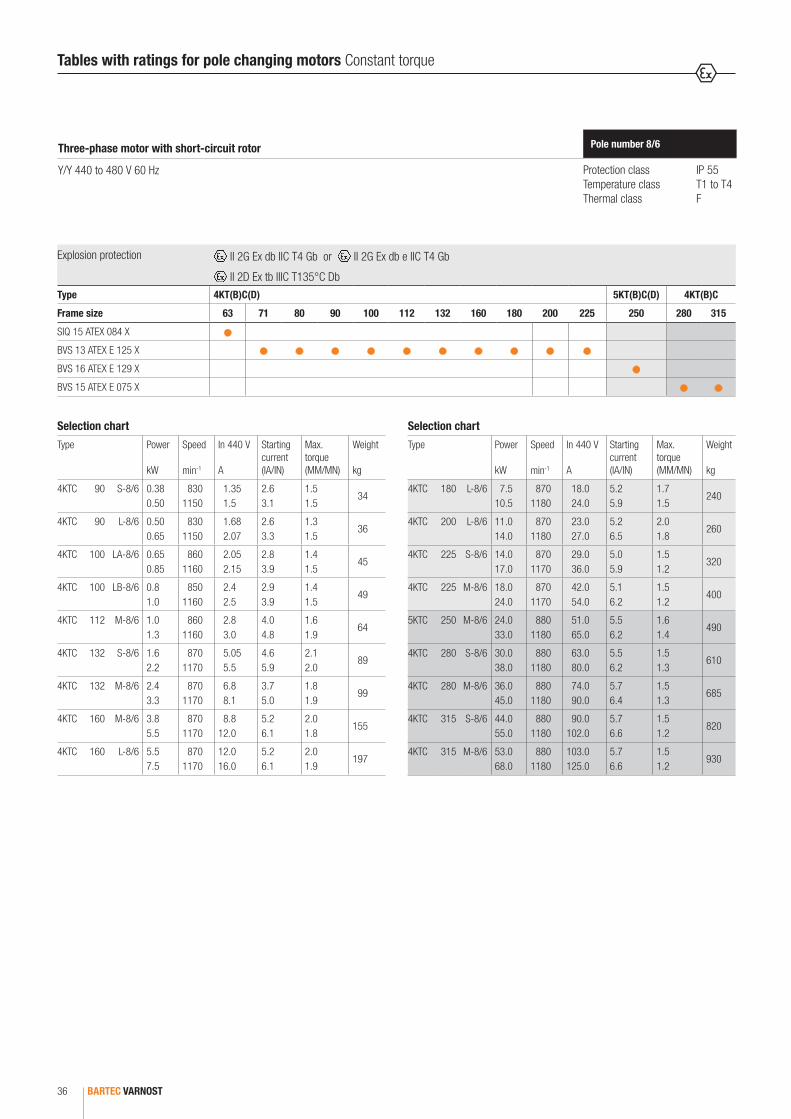
BARTEC VARNOST36
Protection class IP 55Temperature class T1 to T4Thermal class F
Pole number 8/6Three-phase motor with short-circuit rotor
Y/Y 440 to 480 V 60 Hz
Selection chart
Type Power
kW
Speed
min-1
In 440 V
A
Starting current (IA/IN)
Max.torque (MM/MN)
Weight
kg
4KTC 90 S-8/6 0.38 0.50
830 1150
1.35 1.5
2.6 3.1
1.5 1.5
34
4KTC 90 L-8/6 0.50 0.65
830 1150
1.68 2.07
2.6 3.3
1.3 1.5
36
4KTC 100 LA-8/6 0.65 0.85
860 1160
2.05 2.15
2.8 3.9
1.4 1.5
45
4KTC 100 LB-8/6 0.8 1.0
850 1160
2.4 2.5
2.9 3.9
1.4 1.5
49
4KTC 112 M-8/6 1.0 1.3
860 1160
2.8 3.0
4.0 4.8
1.6 1.9
64
4KTC 132 S-8/6 1.6 2.2
870 1170
5.05 5.5
4.6 5.9
2.1 2.0
89
4KTC 132 M-8/6 2.4 3.3
870 1170
6.8 8.1
3.7 5.0
1.8 1.9
99
4KTC 160 M-8/6 3.8 5.5
870 1170
8.8 12.0
5.2 6.1
2.0 1.8
155
4KTC 160 L-8/6 5.5 7.5
870 1170
12.0 16.0
5.2 6.1
2.0 1.9
197
Selection chart
Type Power
kW
Speed
min-1
In 440 V
A
Starting current (IA/IN)
Max.torque (MM/MN)
Weight
kg
4KTC 180 L-8/6 7.5 10.5
870 1180
18.0 24.0
5.2 5.9
1.7 1.5
240
4KTC 200 L-8/6 11.0 14.0
870 1180
23.0 27.0
5.2 6.5
2.0 1.8
260
4KTC 225 S-8/6 14.0 17.0
870 1170
29.0 36.0
5.0 5.9
1.5 1.2
320
4KTC 225 M-8/6 18.0 24.0
870 1170
42.0 54.0
5.1 6.2
1.5 1.2
400
5KTC 250 M-8/6 24.0 33.0
880 1180
51.0 65.0
5.5 6.2
1.6 1.4
490
4KTC 280 S-8/6 30.0 38.0
880 1180
63.0 80.0
5.5 6.2
1.5 1.3
610
4KTC 280 M-8/6 36.0 45.0
880 1180
74.0 90.0
5.7 6.4
1.5 1.3
685
4KTC 315 S-8/6 44.0 55.0
880 1180
90.0 102.0
5.7 6.6
1.5 1.2
820
4KTC 315 M-8/6 53.0 68.0
880 1180
103.0 125.0
5.7 6.6
1.5 1.2
930
Tables with ratings for pole changing motors Constant torque
Explosion protection II 2G Ex db IIC T4 Gb or II 2G Ex db e IIC T4 Gb
II 2D Ex tb IIIC T135°C DbType 4KT(B)C(D) 5KT(B)C(D) 4KT(B)C
Frame size 63 71 80 90 100 112 132 160 180 200 225 250 280 315
SIQ 15 ATEX 084 X
BVS 13 ATEX E 125 X
BVS 16 ATEX E 129 X
BVS 15 ATEX E 075 X
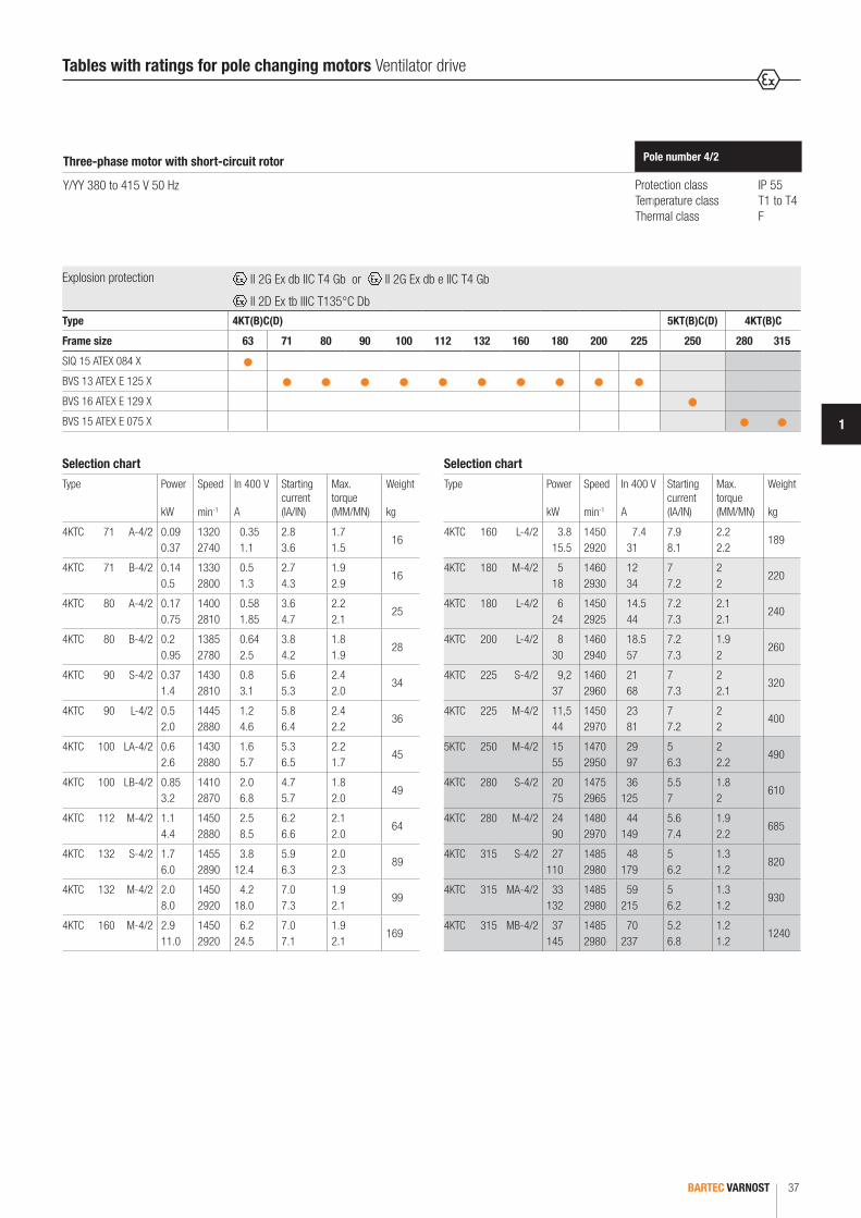
BARTEC VARNOST 37
1
Protection class IP 55Temperature class T1 to T4Thermal class F
Pole number 4/2Three-phase motor with short-circuit rotor
Y/YY 380 to 415 V 50 Hz
Selection chart
Type Power
kW
Speed
min-1
In 400 V
A
Starting current (IA/IN)
Max.torque (MM/MN)
Weight
kg
4KTC 71 A-4/2 0.09 0.37
1320 2740
0.35 1.1
2.8 3.6
1.7 1.5
16
4KTC 71 B-4/2 0.14 0.5
1330 2800
0.5 1.3
2.7 4.3
1.9 2.9
16
4KTC 80 A-4/2 0.17 0.75
1400 2810
0.58 1.85
3.6 4.7
2.2 2.1
25
4KTC 80 B-4/2 0.2 0.95
1385 2780
0.64 2.5
3.8 4.2
1.8 1.9
28
4KTC 90 S-4/2 0.37 1.4
1430 2810
0.8 3.1
5.6 5.3
2.4 2.0
34
4KTC 90 L-4/2 0.5 2.0
1445 2880
1.2 4.6
5.8 6.4
2.4 2.2
36
4KTC 100 LA-4/2 0.6 2.6
1430 2880
1.6 5.7
5.3 6.5
2.2 1.7
45
4KTC 100 LB-4/2 0.85 3.2
1410 2870
2.0 6.8
4.7 5.7
1.8 2.0
49
4KTC 112 M-4/2 1.1 4.4
1450 2880
2.5 8.5
6.2 6.6
2.1 2.0
64
4KTC 132 S-4/2 1.7 6.0
1455 2890
3.8 12.4
5.9 6.3
2.0 2.3
89
4KTC 132 M-4/2 2.0 8.0
1450 2920
4.2 18.0
7.0 7.3
1.9 2.1
99
4KTC 160 M-4/2 2.9 11.0
1450 2920
6.2 24.5
7.0 7.1
1.9 2.1
169
Selection chart
Type Power
kW
Speed
min-1
In 400 V
A
Starting current (IA/IN)
Max.torque (MM/MN)
Weight
kg
4KTC 160 L-4/2 3.8 15.5
1450 2920
7.4 31
7.9 8.1
2.2 2.2
189
4KTC 180 M-4/2 5 18
1460 2930
12 34
7 7.2
2 2
220
4KTC 180 L-4/2 6 24
1450 2925
14.5 44
7.2 7.3
2.1 2.1
240
4KTC 200 L-4/2 8 30
1460 2940
18.5 57
7.2 7.3
1.9 2
260
4KTC 225 S-4/2 9,2 37
1460 2960
21 68
7 7.3
2 2.1
320
4KTC 225 M-4/2 11,5 44
1450 2970
23 81
7 7.2
2 2
400
5KTC 250 M-4/2 15 55
1470 2950
29 97
5 6.3
2 2.2
490
4KTC 280 S-4/2 20 75
1475 2965
36 125
5.5 7
1.8 2
610
4KTC 280 M-4/2 24 90
1480 2970
44 149
5.6 7.4
1.9 2.2
685
4KTC 315 S-4/2 27 110
1485 2980
48 179
5 6.2
1.3 1.2
820
4KTC 315 MA-4/2 33 132
1485 2980
59 215
5 6.2
1.3 1.2
930
4KTC 315 MB-4/2 37 145
1485 2980
70 237
5.2 6.8
1.2 1.2
1240
Tables with ratings for pole changing motors Ventilator drive
Explosion protection II 2G Ex db IIC T4 Gb or II 2G Ex db e IIC T4 Gb
II 2D Ex tb IIIC T135°C DbType 4KT(B)C(D) 5KT(B)C(D) 4KT(B)C
Frame size 63 71 80 90 100 112 132 160 180 200 225 250 280 315
SIQ 15 ATEX 084 X
BVS 13 ATEX E 125 X
BVS 16 ATEX E 129 X
BVS 15 ATEX E 075 X

BARTEC VARNOST38
Tables with ratings for pole changing motors Ventilator drive
Protection class IP 55Temperature class T1 to T4Thermal class F
Pole number 8/4Three-phase motor with short-circuit rotor
Y/YY 380 to 415 V 50 Hz
Selection chart
Type Power
kW
Speed
min-1
In 400 V
A
Starting current (IA/IN)
Max.torque (MM/MN)
Weight
kg
4KTC 71 A-8/4 0.05 0.2
700 1420
0.39 0.82
1.7 3.5
1.4 1.8
16
4KTC 71 B-8/4 0.07 0.3
680 1390
0.44 0.95
1.8 3.6
1.6 1.8
17
4KTC 80 A-8/4 0.1 0.45
690 1425
0.53 1.45
2.4 4.7
1.7 2.4
25
4KTC 80 B-8/4 0.13 0.6
690 1435
0.69 1.9
2.35 4.7
1.9 2.7
28
4KTC 90 S-8/4 0.18 0.8
700 1415
0.76 1.9
2.8 5.0
1.8 2.0
34
4KTC 90 L-8/4 0.3 1.2
700 1435
1.24 2.9
3.0 5.6
2.0 2.3
36
4KTC 100 LA-8/4 0.33 1.6
710 1435
1.45 3.7
3.1 5.1
1.3 1.5
45
4KTC 100 LB-8/4 0.55 2.2
695 1430
2.0 4.9
2.8 5.0
1.6 1.8
49
4KTC 112 M-8/4 0.75 3.0
705 1440
2.44 6.1
3.2 6.5
1.7 2.0
64
4KTC 132 S-8/4 1.1 4.4
710 1450
3.5 9.0
2.8 5.3
1.5 2.0
89
4KTC 132 M-8/4 1.3 5.1
720 1460
4.0 10.2
3.5 6.9
3.1 2.6
99
4KTC 160 MA-8/4 1.8 7.5
725 1465
4.6 14.8
5.3 7.6
1.8 2.0
155
Selection chart
Type Power
kW
Speed
min-1
In 400 V
A
Starting current (IA/IN)
Max.torque (MM/MN)
Weight
kg
4KTC 160 MB-8/4 3.0 10.0
725 1470
10.0 22.0
3.3 6.6
1.9 2.7
165
4KTC 180 M-8/4 4.0 16.0
735 1465
13.0 30.0
4.5 6.1
1.9 2.4
220
4KTC 180 L-8/4 4.5 19.0
730 1470
14.5 38.5
4.0 6.6
2.1 2.4
240
4KTC 200 L-8/4 6.2 25.0
720 1470
14.5 46.0
4.4 6.8
2.2 2.3
260
4KTC 225 S-8/4 7.5 30.0
725 1470
19.0 60.0
4.6 6.7
2.3 2.4
320
4KTC 225 M-8/4 9.0 37.0
730 1475
22.0 67.0
4.8 7.0
2.4 2.8
400
5KTC 250 M-8/4 12.0 48.0
730 1475
24.5 82.0
5.0 5.8
2.2 2.4
490
4KTC 280 S-8/4 16.0 65.0
740 1485
42.0 127.0
4.3 7.5
1.8 2.1
610
4KTC 280 M-8/4 20.0 80.0
740 1485
48.0 140.0
4.3 7.5
1.8 2.2
685
4KTC 315 S-8/4 24.0 98.0
735 1485
45.0 165.0
4.6 7.0
1.4 1.8
820
4KTC 315 M-8/4 30.0 120.0
740 1485
52.0 196.0
4.6 7.0
1.4 1.8
930
Explosion protection II 2G Ex db IIC T4 Gb or II 2G Ex db e IIC T4 Gb
II 2D Ex tb IIIC T135°C DbType 4KT(B)C(D) 5KT(B)C(D) 4KT(B)C
Frame size 63 71 80 90 100 112 132 160 180 200 225 250 280 315
SIQ 15 ATEX 084 X
BVS 13 ATEX E 125 X
BVS 16 ATEX E 129 X
BVS 15 ATEX E 075 X
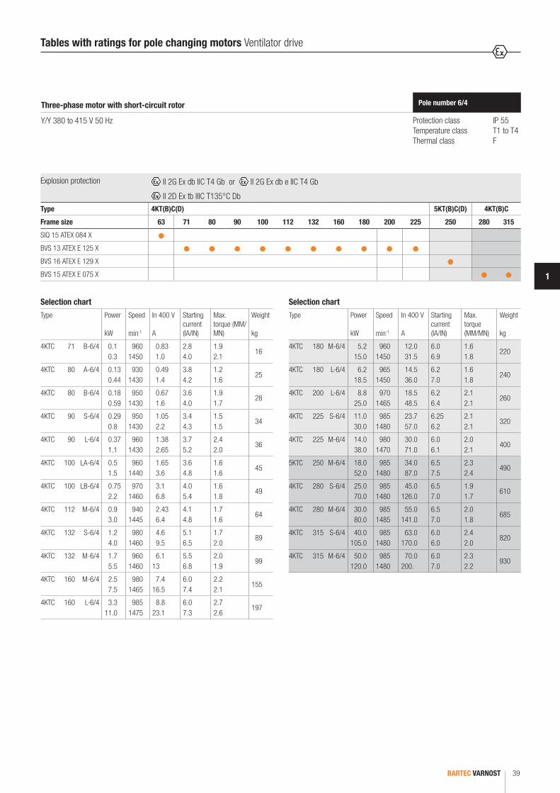
BARTEC VARNOST 39
1
Tables with ratings for pole changing motors Ventilator drive
Protection class IP 55Temperature class T1 to T4Thermal class F
Pole number 6/4Three-phase motor with short-circuit rotor
Y/Y 380 to 415 V 50 Hz
Selection chart
Type Power
kW
Speed
min-1
In 400 V
A
Starting current (IA/IN)
Max.torque (MM/MN)
Weight
kg
4KTC 71 B-6/4 0.1 0.3
960 1450
0.83 1.0
2.8 4.0
1.9 2.1
16
4KTC 80 A-6/4 0.13 0.44
930 1430
0.49 1.4
3.8 4.2
1.2 1.6
25
4KTC 80 B-6/4 0.18 0.59
950 1430
0.67 1.6
3.6 4.0
1.9 1.7
28
4KTC 90 S-6/4 0.29 0.8
950 1430
1.05 2.2
3.4 4.3
1.5 1.5
34
4KTC 90 L-6/4 0.37 1.1
960 1430
1.38 2.65
3.7 5.2
2.4 2.0
36
4KTC 100 LA-6/4 0.5 1.5
960 1440
1.65 3.6
3.6 4.8
1.6 1.6
45
4KTC 100 LB-6/4 0.75 2.2
970 1460
3.1 6.8
4.0 5.4
1.6 1.8
49
4KTC 112 M-6/4 0.9 3.0
940 1445
2.43 6.4
4.1 4.8
1.7 1.6
64
4KTC 132 S-6/4 1.2 4.0
980 1460
4.6 9.5
5.1 6.5
1.7 2.0
89
4KTC 132 M-6/4 1.7 5.5
960 1460
6.1 13
5.5 6.8
2.0 1.9
99
4KTC 160 M-6/4 2.5 7.5
980 1465
7.4 16.5
6.0 7.4
2.2 2.1
155
4KTC 160 L-6/4 3.3 11.0
985 1475
8.8 23.1
6.0 7.3
2.7 2.6
197
Selection chart
Type Power
kW
Speed
min-1
In 400 V
A
Starting current (IA/IN)
Max.torque (MM/MN)
Weight
kg
4KTC 180 M-6/4 5.2 15.0
960 1450
12.0 31.5
6.0 6.9
1.6 1.8
220
4KTC 180 L-6/4 6.2 18.5
965 1450
14.5 36.0
6.2 7.0
1.6 1.8
240
4KTC 200 L-6/4 8.8 25.0
970 1465
18.5 48.5
6.2 6.4
2.1 2.1
260
4KTC 225 S-6/4 11.0 30.0
985 1480
23.7 57.0
6.25 6.2
2.1 2.1
320
4KTC 225 M-6/4 14.0 38.0
980 1470
30.0 71.0
6.0 6.1
2.0 2.1
400
5KTC 250 M-6/4 18.0 52.0
985 1480
34.0 87.0
6.5 7.5
2.3 2.4
490
4KTC 280 S-6/4 25.0 70.0
985 1480
45.0 126.0
6.5 7.0
1.9 1.7
610
4KTC 280 M-6/4 30.0 80.0
985 1485
55.0 141.0
6.5 7.0
2.0 1.8
685
4KTC 315 S-6/4 40.0 105.0
985 1480
63.0 170.0
6.0 6.0
2.4 2.0
820
4KTC 315 M-6/4 50.0 120.0
985 1480
70.0 200.
6.0 7.0
2.3 2.2
930
Explosion protection II 2G Ex db IIC T4 Gb or II 2G Ex db e IIC T4 Gb
II 2D Ex tb IIIC T135°C DbType 4KT(B)C(D) 5KT(B)C(D) 4KT(B)C
Frame size 63 71 80 90 100 112 132 160 180 200 225 250 280 315
SIQ 15 ATEX 084 X
BVS 13 ATEX E 125 X
BVS 16 ATEX E 129 X
BVS 15 ATEX E 075 X
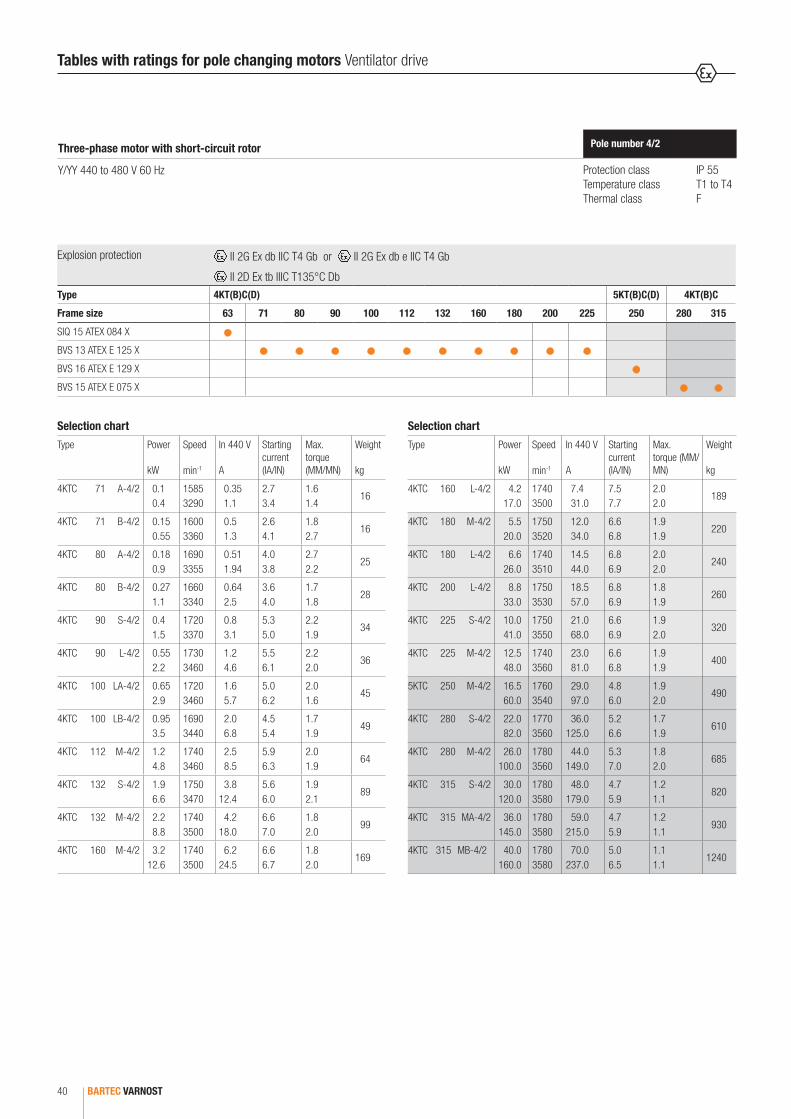
BARTEC VARNOST40
Protection class IP 55Temperature class T1 to T4Thermal class F
Pole number 4/2Three-phase motor with short-circuit rotor
Y/YY 440 to 480 V 60 Hz
Selection chart
Type Power
kW
Speed
min-1
In 440 V
A
Starting current (IA/IN)
Max.torque (MM/MN)
Weight
kg
4KTC 71 A-4/2 0.1 0.4
1585 3290
0.35 1.1
2.7 3.4
1.6 1.4
16
4KTC 71 B-4/2 0.15 0.55
1600 3360
0.5 1.3
2.6 4.1
1.8 2.7
16
4KTC 80 A-4/2 0.18 0.9
1690 3355
0.51 1.94
4.0 3.8
2.7 2.2
25
4KTC 80 B-4/2 0.27 1.1
1660 3340
0.64 2.5
3.6 4.0
1.7 1.8
28
4KTC 90 S-4/2 0.4 1.5
1720 3370
0.8 3.1
5.3 5.0
2.2 1.9
34
4KTC 90 L-4/2 0.55 2.2
1730 3460
1.2 4.6
5.5 6.1
2.2 2.0
36
4KTC 100 LA-4/2 0.65 2.9
1720 3460
1.6 5.7
5.0 6.2
2.0 1.6
45
4KTC 100 LB-4/2 0.95 3.5
1690 3440
2.0 6.8
4.5 5.4
1.7 1.9
49
4KTC 112 M-4/2 1.2 4.8
1740 3460
2.5 8.5
5.9 6.3
2.0 1.9
64
4KTC 132 S-4/2 1.9 6.6
1750 3470
3.8 12.4
5.6 6.0
1.9 2.1
89
4KTC 132 M-4/2 2.2 8.8
1740 3500
4.2 18.0
6.6 7.0
1.8 2.0
99
4KTC 160 M-4/2 3.2 12.6
1740 3500
6.2 24.5
6.6 6.7
1.8 2.0
169
Selection chart
Type Power
kW
Speed
min-1
In 440 V
A
Starting current (IA/IN)
Max.torque (MM/MN)
Weight
kg
4KTC 160 L-4/2 4.2 17.0
1740 3500
7.4 31.0
7.5 7.7
2.0 2.0
189
4KTC 180 M-4/2 5.5 20.0
1750 3520
12.0 34.0
6.6 6.8
1.9 1.9
220
4KTC 180 L-4/2 6.6 26.0
1740 3510
14.5 44.0
6.8 6.9
2.0 2.0
240
4KTC 200 L-4/2 8.8 33.0
1750 3530
18.5 57.0
6.8 6.9
1.8 1.9
260
4KTC 225 S-4/2 10.0 41.0
1750 3550
21.0 68.0
6.6 6.9
1.9 2.0
320
4KTC 225 M-4/2 12.5 48.0
1740 3560
23.0 81.0
6.6 6.8
1.9 1.9
400
5KTC 250 M-4/2 16.5 60.0
1760 3540
29.0 97.0
4.8 6.0
1.9 2.0
490
4KTC 280 S-4/2 22.0 82.0
1770 3560
36.0 125.0
5.2 6.6
1.7 1.9
610
4KTC 280 M-4/2 26.0 100.0
1780 3560
44.0 149.0
5.3 7.0
1.8 2.0
685
4KTC 315 S-4/2 30.0 120.0
1780 3580
48.0 179.0
4.7 5.9
1.2 1.1
820
4KTC 315 MA-4/2 36.0 145.0
1780 3580
59.0 215.0
4.7 5.9
1.2 1.1
930
4KTC 315 MB-4/2 40.0 160.0
1780 3580
70.0 237.0
5.0 6.5
1.1 1.1
1240
Explosion protection II 2G Ex db IIC T4 Gb or II 2G Ex db e IIC T4 Gb
II 2D Ex tb IIIC T135°C DbType 4KT(B)C(D) 5KT(B)C(D) 4KT(B)C
Frame size 63 71 80 90 100 112 132 160 180 200 225 250 280 315
SIQ 15 ATEX 084 X
BVS 13 ATEX E 125 X
BVS 16 ATEX E 129 X
BVS 15 ATEX E 075 X
Tables with ratings for pole changing motors Ventilator drive

BARTEC VARNOST 41
1
Protection class IP 55Temperature class T1 to T4Thermal class F
Pole number 8/4Three-phase motor with short-circuit rotor
Y/YY 440 to 480 V 60 Hz
Selection chart
Type Power
kW
Speed
min-1
In 440 V
A
Starting current (IA/IN)
Max.torque (MM/MN)
Weight
kg
4KTC 71 A-8/4 0.06 0.22
840 1700
0.39 0.82
1.6 3.3
1.3 1.7
16
4KTC 71 B-8/4 0.08 0.33
820 1670
0.44 0.95
1.7 3.4
1.5 1.7
17
4KTC 80 A-8/4 0.11 0.5
830 1710
0.53 1.45
2.3 4.5
1.6 2.2
25
4KTC 80 B-8/4 0.14 0.65
830 1720
0.69 1.9
2.2 4.5
1.8 2.5
28
4KTC 90 S-8/4 0.2 0.9
840 1700
0.76 1.9
4.8 2.7
1.7 1.9
34
4KTC 90 L-8/4 0.33 1.32
834 1715
1.16 2.9
3.4 5.15
2.1 2.7
36
4KTC 100 LA-8/4 0.45 2.0
840 1705
1.4 3.95
2.9 4.7
1.2 1.4
45
4KTC 100 LB-8/4 0.6 2.4
845 1730
2.15 5.1
3.0 5.5
2.1 2.7
49
4KTC 112 M-8/4 0.8 3.3
850 1730
2.44 6.1
3.0 6.2
1.6 1.9
64
4KTC 132 S-8/4 1.2 4.8
850 1740
3.5 9.0
2.7 5.0
1.4 1.9
89
4KTC 132 M-8/4 1.15 5.75
865 1745
3.45 10.4
3.7 6.5
2.9 2.4
99
4KTC 160 MA-8/4 1.6 8.0
875 1755
4.0 14.2
5.6 7.3
1.7 1.9
155
Selection chart
Type Power
kW
Speed
min-1
In 440 V
A
Starting current (IA/IN)
Max.torque (MM/MN)
Weight
kg
4KTC 160 MB-8/4 3.3 11.0
870 1760
10.0 22.0
3.1 6.3
1.8 2.5
165
4KTC 180 M-8/4 4.4 17.6
875 1765
11.2 31.0
3.8 6.5
1.7 2.3
220
4KTC 180 L-8/4 4.5 18.0
880 1775
12.8 33.0
4.0 7.6
2.0 2.2
240
4KTC 200 L-8/4 6.0 30.0
885 1775
14.3 51.0
6.4 8.7
2.0 2.1
260
4KTC 225 S-8/4 9.0 35.0
870 1760
19.0 60.0
4.4 6.4
2.1 2.2
320
4KTC 225 M-8/4 10.0 41.0
880 1770
22.0 67.0
4.6 6.7
2.2 2.6
400
5KTC 250 M-8/4 11.0 50.0
880 1770
24.5 82.0
4.8 5.5
2.0 2.2
490
4KTC 280 S-8/4 19.0 75.0
890 1780
42.0 127.0
4.1 7.1
1.7 2.0
610
4KTC 280 M-8/4 22.0 88.0
890 1780
48.0 140.0
4.1 7.1
1.7 2.0
685
4KTC 315 S-8/4 24.0 105.0
880 1780
45.0 165.0
4.4 6.7
1.3 1.7
820
4KTC 315 M-8/4 29.0 126.0
890 1780
52.0 196.0
4.4 6.7
1.3 1.7
930
Explosion protection II 2G Ex db IIC T4 Gb or II 2G Ex db e IIC T4 Gb
II 2D Ex tb IIIC T135°C DbType 4KT(B)C(D) 5KT(B)C(D) 4KT(B)C
Frame size 63 71 80 90 100 112 132 160 180 200 225 250 280 315
SIQ 15 ATEX 084 X
BVS 13 ATEX E 125 X
BVS 16 ATEX E 129 X
BVS 15 ATEX E 075 X
Tables with ratings for pole changing motors Ventilator drive

BARTEC VARNOST42
Tables with ratings for pole changing motors Ventilator drive
Protection class IP 55Temperature class T1 to T4Thermal class F
Pole number 6/4Three-phase motor with short-circuit rotor
Y/Y 440 to 480 V 60 Hz
Selection chart
Type Power
kW
Speed
min-1
In 440 V
A
Starting current (IA/IN)
Max.torque (MM/MN)
Weight
kg
4KTC 71 B-6/4 0.11 0.33
1150 1740
0.83 1.0
2.7 1.0
1.8 2.0
16
4KTC 80 A-6/4 0.14 0.48
1120 1720
0.49 1.4
3.6 4.0
1.1 1.5
25
4KTC 80 B-6/4 0.2 0.65
1140 1720
0.67 1.6
3.4 3.8
1.8 1.6
28
4KTC 90 S-6/4 0.32 0.88
1140 1720
1.05 2.2
3.2 4.1
1.4 1.4
34
4KTC 90 L-6/4 0.4 1.2
1150 1720
1.38 2.65
3.5 4.9
2.2 1.9
36
4KTC 100 LA-6/4 0.55 1.65
1150 1730
1.65 3.6
3.4 4.6
1.5 1.5
45
4KTC 100 LB-6/4 0.82 2.4
1160 1750
3.1 6.8
3.8 5.1
1.5 1.7
49
4KTC 112 M-6/4 1.0 3.3
1130 1730
2.43 6.4
3.9 4.6
1.6 1.5
64
4KTC 132 S-6/4 1.3 4.4
1180 1750
4.6 9.5
4.8 6.2
1.6 1.9
89
4KTC 132 M-6/4 1.9 6.0
1150 1750
6.1 13
5.2 6.5
1.9 1.8
99
4KTC 160 M-6/4 2.7 8.2
1180 1760
7.4 16.5
5.7 7.0
2.0 2.0
155
4KTC 160 L-6/4 3.6 12.0
1180 1770
8.8 23.1
5.7 6.9
2.5 2.4
197
Selection chart
Type Power
kW
Speed
min-1
In 440 V
A
Starting current (IA/IN)
Max.torque (MM/MN)
Weight
kg
4KTC 180 M-6/4 5.7 16.5
1150 1740
12.0 31.5
5.7 6.6
1.5 1.7
220
4KTC 180 L-6/4 6.8 20.0
1160 1740
14.5 36.0
5.9 6.6
1.5 1.7
240
4KTC 200 L-6/4 10.0 28.0
1160 1760
18.5 48.5
5.9 6.1
2.0 2.0
260
4KTC 225 S-6/4 12.0 33.0
1180 1780
23.7 57.0
5.9 6.2
2.0 2.0
320
4KTC 225 M-6/4 15.0 42.0
1180 1760
30.0 71.0
5.7 5.8
1.9 2.0
400
5KTC 250 M-6/4 19.0 53.0
1180 1780
34.0 87.0
6.2 7.1
2.1 2.2
490
4KTC 280 S-6/4 27.0 77.0
1180 1780
45.0 126.0
6.2 6.7
1.8 1.6
610
4KTC 280 M-6/4 33.0 90.0
1180 1780
55.0 141.0
6.2 6.7
1.9 1.7
685
4KTC 315 S-6/4 35.0 105.0
1180 1780
63.0 170.0
5.7 5.7
2.2 1.9
820
4KTC 315 M-6/4 41.0 126.0
1180 1780
70.0 200.0
5.7 6.7
2.1 2.0
930
Explosion protection II 2G Ex db IIC T4 Gb or II 2G Ex db e IIC T4 Gb
II 2D Ex tb IIIC T135°C DbType 4KT(B)C(D) 5KT(B)C(D) 4KT(B)C
Frame size 63 71 80 90 100 112 132 160 180 200 225 250 280 315
SIQ 15 ATEX 084 X
BVS 13 ATEX E 125 X
BVS 16 ATEX E 129 X
BVS 15 ATEX E 075 X

BARTEC VARNOST 43
1
Three-phase electric motors driven by frequency inverters
UN = net voltage
UFR = voltage of frequency inverter
MN = motor torque on net
MFR = motor torque on frequency inverter
MN = const UN = const
General description
The asynchronous motor with its short-circuit rotor and robust construction offers an excellent price-performance ratio. AC motors are designed for constant speed operation. It is not possible to change speed when they are running on fixed frequency supplies. There are drives which require the additional flexibility of smooth speed variations and this is best achieved with with the use of an inverter.Frequency inverters provide an excellent speed and the speed can be varied continuously over the entire frequency range. To avoid overheating, three PTC elements are built into the head of the winding. As the speed rises (higher frequency), the motor becomes louder. Voltage type frequency inverters cause a noise increase of about 7 to 15 dB, current type ones of about 3 dB.We strongly recommend that you indicate frequency range and working characteristics of the motor (T = f (n) or P = f (n)) when placing your order.
Power and torque characteristics of motors driven by frequency inverters
We distinguish two ranges:
0 to 50 Hz rangeHere the motor develops its normal torque on the shaft at 5 to 10 Hz of the output frequency (10 to 20 % of the nominal speed). The motor maintains the nominal torque at the shaft until the frequency reaches 50 Hz (100 % of the nominal speed). Voltage keeps rising while the magnetic flux is kept constant. The power increase in this range is linear to the revolutions (P = k x M x n).
50 to 87 Hz rangeHere the torque falls parallel to the speed. The voltage of the motor is main-tained on a constant level while the magnetic flux is weaker. The current level is maintained and independent of the speed.

BARTEC VARNOST44
Three-phase electric motors driven by frequency inverters
Pole number 2Three-phase motor with short-circuit rotor
Explosion protection: II 2G Ex d IIC T4 or II 2G Ex de IIC T4
* range 60 to 87 Hz, motors with steel fan ** U = 230/400 V
Selection chart
Operating net frequency inverter
Cooling own own own own own own forced cooling own
Torque T - n2 constant constant constant constant constant constant
Frequency 50 Hz 5 to 50 Hz 20 to 50 Hz 10 to 50 Hz 5 to 50 Hz 50 to 87 Hz 5 to 87 Hz 50 to 87 Hz*
Ratio 1 : 10 1 : 2.5 1 : 5 1 : 10 1 : 1.74 1 : 17.4 1 : 1.74
RPM 300 - 3000 min-1 1200 - 3000 min-1 600 - 3000 min-1 300 - 3000 min-1 3000 - 5220 min-1 300 - 5220 min-1 3000 - 5220 min-1
V/f U/f = const U/f = const U/f = const U/f = const U = const U = const U/f = const**
Type PowerkW
Power50 Hz
TorqueNm
Power50 Hz
TorqueNm
Power50 Hz
TorqueNm
Power50 Hz
TorqueNm
Power87 Hz
TorqueNm
Power87 Hz
TorqueNm
Power87 Hz
Torque Nm
4KTC 71 A-2 B-2
0.37 0.55
0.35 0.53
1.12 1.7
0.32 0.47
1.07 1.62
0.3 0.45
0.97 1.47
0.22 0.33
0.74 1.1
0.35 0.53
0.65 0.98
0.35 0.53
0.65 0.98
0.6 0.9
1.12 1.7
4KTC 80 A-2 B-2
0.75 1.1
0.72 1.0
2.3 3.4
0.65 0.95
2.2 3.25
0.6 0.9
2.0 3.0
0.5 0.75
1.7 2.5
0.7 1.1
1.33 2.0
0.7 1.1
1.33 2.0
1.2 1.8
2.3 3.4
4KTC 90 S-2 L-2
1.5 2.2
1.4 2.1
4.5 6.7
1.3 1.9
4.3 6.4
1.2 1.7
4.0 5.7
1.0 1.4
3.3 4.7
1.4 2.1
2.6 3.8
1.4 2.1
2.6 3.8
2.5 3.7
4.5 6.7
4KTC 100 L-2 3.0 2.8 9.0 2.6 8.6 2.2 7.2 1.8 5.9 2.8 5.2 2.8 5.2 4.9 9.0
4KTC 112 M-2 4.0 3.8 12.0 3.4 11.4 3.2 10.4 2.5 8.2 3.8 6.9 3.8 6.9 6.5 12.0
4KTC 132 SA-2 SB-2
5.5 7.5
5.1 6.9
16.3 22.0
4.7 6.5
15.6 21.1
4.5 6.0
14.1 19.1
3.7 5.0
12.0 16.0
5.1 7.0
9.4 12.7
5.1 7.0
9.4 12.7
8.9 12.0
16.3 22.0
4KTC 160 MA-2 MB-2
L-2
11.0 15.0 18.5
10.0 13.5 16.6
32.2 43.8 54.0
9.5 12.9 15.9
30.8 41.9 51.6
8.8 12.0 15.0
27.9 38.0 46.8
7.5 10.0 12.0
24.0 32.0 41.0
10.2 13.8 17.0
18.6 25.3 31.2
10.2 13.8 17.0
18.6 25.3 31.2
17.6 24.0 29.5
32.2 43.8 54.0
4KTC 180 M-2 22.0 20.0 64.4 18.9 61.5 18.0 55.8 15.0 49.0 20.3 37.2 20.3 37.2 35.0 64.4
4KTC 200 LA-2 LB-2
30.0 37.0
27.0 33.0
87.0 107.0
25.8 31.8
83.4 102.4
24.0 28.0
75.7 90.0
21.0 26.0
68.0 84.0
27.6 34.0
50.4 62.0
27.6 34.0
50.4 62.0
47.0 58.0
87.0 107.0
4KTC 225 M-2 45.0 40.0 130.0 37.0 119.0 34.0 110.0 32.0 101.0 - - - - - -
5KTC 250 M-2 55.0 50.0 159.0 45.0 145.0 43.0 138.0 39.0 124.0 - - - - - -
4KTC 280 S-2 M-2
75.0 90.0
67.0 81.0
217.0 260.0
60.0 73.0
193.0 234.0
58.0 70.0
186.0 225.0
53.0 63.0
169.0 202.0
- -
- -
- -
- -
- -
- -
4KTC 315 S-2 MA-2 MA-2
L-2
110.0 132.0 160.0 200.0
100.0 119.0 144.0 180.0
318.0 382.0 458.0 575.0
90.0 110.0 135.0 165.0
288.0 353.0 433.0 528.0
88.0 105.0 125.0 156.0
282.0 331.0 398.0 498.0
78.0 93.0 112.0 140.0
247.0 297.0 358.0 447.0
- - - -
- - - -
- - - -
- - - -
- - - -
- - - -

BARTEC VARNOST 45
1
Three-phase electric motors driven by frequency inverters
Pole number 4Three-phase motor with short-circuit rotor
Explosion protection: II 2G Ex d IIC T4 or II 2G Ex de IIC T4
* range 60 to 87 Hz, motors with steel fan ** U = 230/400 V
Selection chart
Operating net frequency inverter
Cooling own own own own own own forced cooling own
Torque T - n2 constant constant constant constant constant constant
Frequency 50 Hz 5 to 50 Hz 20 to 50 Hz 10 to 50 Hz 5 to 50 Hz 50 to 87 Hz 5 to 87 Hz 50 to 87 Hz*
Ratio 1 : 10 1 : 2.5 1 : 5 1 : 10 1 : 1.74 1 : 17.4 1 : 1.74
RPM 150 - 1500 min-1 600 - 1500 min-1 300 - 1500 min-1 150 - 1500 min-1 1500 - 2610 min-1 150 - 2610 min-1 1500 - 2610 min-1
V/f U/f = const U/f = const U/f = const U/f = const U = const U = const U/f = const**
Type PowerkW
Power50 Hz
TorqueNm
Power50 Hz
TorqueNm
Power50 Hz
TorqueNm
Power50 Hz
TorqueNm
Power87 Hz
TorqueNm
Power87 Hz
TorqueNm
Power87 Hz
Torque Nm
KTC 71 A-4 B-4
0.25 0.37
0.25 0,36
1.57 2.3
0.23 0.34
1.5 2.2
0.21 0.31
1.35 2.0
0.19 0.28
1.2 1.8
0.25 0.35
0.9 1.3
0.25 0.35
0.9 1.3
0.43 0.63
1.57 2.3
4KTC 80 A-4 B-4
0.55 0.75
0,53 0.72
3.38 4.6
0.5 0.69
3.2 4.4
0.45 0.62
2.9 4.0
0.4 0.56
2.6 3.6
0.55 0.71
2.0 2.6
0.55 0.71
2.0 2.6
0.92 1.2
3.38 4.6
4KTC 90 S-4 L-4
1.1 1.5
1.05 1.4
6.7 9.1
1.0 1.4
6.4 8.7
0.9 1.2
5.8 7.9
0.8 1.1
5.2 7.1
1.05 1.4
3.9 5.2
1.05 1.4
3.9 5.2
1.8 2.5
6.7 9.1
4KTC 100 LA-4 LB-4
2.2 3.0
2.1 2.8
13.4 18.2
2.0 2.7
12.8 17.4
1.8 2.5
11.6 15.7
1.6 2.2
10.4 14.1
2.1 2.9
7.7 10.5
2.1 2.9
7.7 10.5
3.6 5.0
13.4 18.2
4KTC 112 M-4 4.0 3.8 24.0 3.6 22.9 3.2 20.7 2.9 18.6 3.8 13.8 3.8 13.8 6.5 24.0
4KTC 132 S-4 M-4
5.5 7.5
5.2 7.0
33.0 44.5
5.0 6.7
31.5 42.6
4.5 6.0
28.5 38.6
4.0 5.4
25.6 34.6
5.2 7.0
19.0 25.7
5.2 7.0
19.0 25.7
9.0 12.0
33.0 44.5
4KTC 160 M-4 L-4
11.0 15.0
10.0 14.0
64.5 88.0
9.7 13.2
61.7 84.0
8.8 12.0
56.0 76.3
7.8 10.7
50.0 68.0
10.2 13.9
37.3 50.8
10.2 13.9
37.3 50.8
17.0 24.0
64.5 88.0
4KTC 180 M-4 L-4
18.5 22.0
17.0 20.0
108.5 129.0
16.3 19.3
104.0 123.0
14.8 17.6
94.0 112.0
13.2 15.7
84.0 100.0
17.1 20.4
62.7 74.5
17.1 20.4
62.7 74.5
30.0 35.0
108.5 129.0
4KTC 200 L-4 30.0 28.0 176.0 26.4 168.0 23.9 152.0 21.0 136.0 27.7 101.5 27.7 101.5 48.0 176.0
4KTC 225 S-4 M-4
37.0 45.0
34.0 41.0
216.0 262.0
32.3 39.3
206.0 250.0
29.4 35.6
187.0 227.0
26.0 32.0
168.0 204.0
34.2 41.0
125.0 151.0
34.2 41.0
125.0 151.0
- -
- -
5KTC 250 M-4 55.0 50.0 320.0 48.0 305.0 43.5 277.0 39.0 248.0 50.0 185.0 50.0 185.0 - -
4KTC 280 S-4 M-4
75.0 90.0
68.0 82.0
434.0 520.0
65.0 78.0
415.0 497.0
59.0 70.0
376.0 450.0
53.0 64.0
337.0 405.0
68.0 82.0
250.0 300.0
68.0 82.0
250.0 300.0
- -
- -
4KTC 315 S-4 MA-4 MB-4
L-4
110.0 132.0 160.0 200.0
100.0 120.0 145.0 180.0
635.0 766.0 924.0 1154.0
95.0 115.0 138.0 173.0
607.0 732.0 883.0 1102.0
86.0 104.0 126.0 157.0
550.0 664.0 801.0 1000.0
77.0 94.0 113.0 140.0
494.0 596.0 719.0 897.0
100.0 121.0 146.0 182.0
367.0 442.0 534.0 666.0
100.0 121.0 146.0 182.0
367.0 442.0 534.0 666.0
- - - -
- - - -
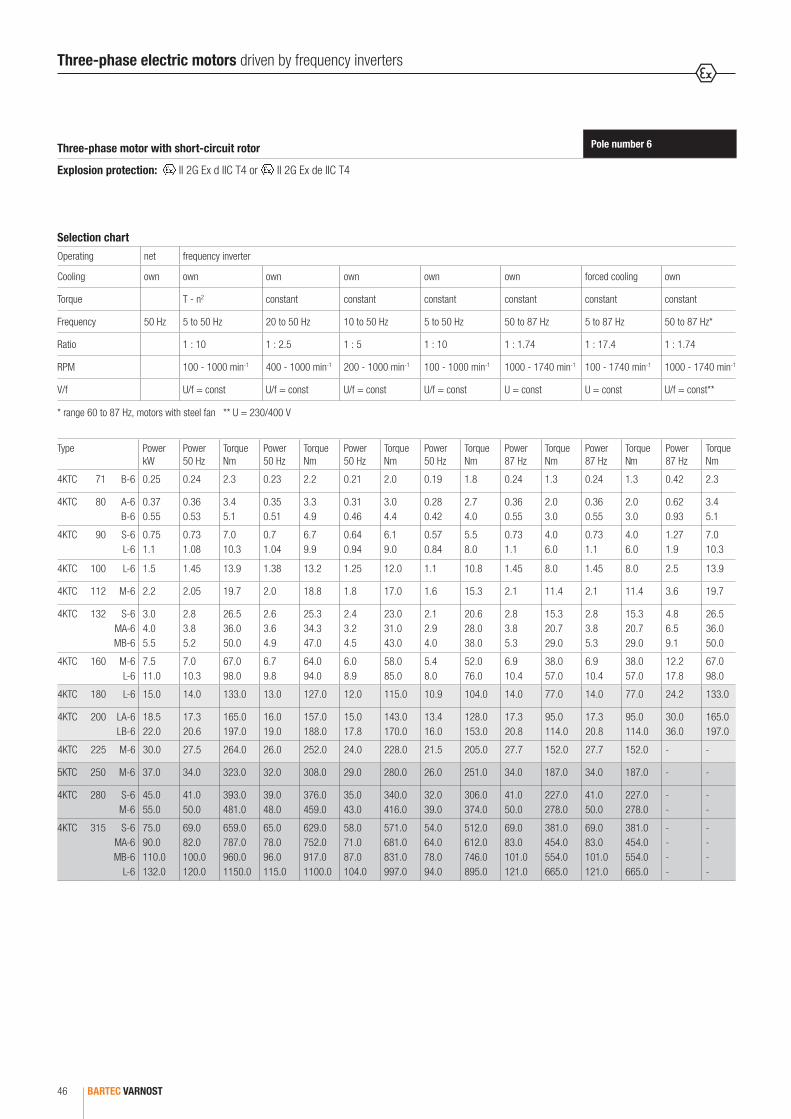
BARTEC VARNOST46
Pole number 6Three-phase motor with short-circuit rotor
Explosion protection: II 2G Ex d IIC T4 or II 2G Ex de IIC T4
* range 60 to 87 Hz, motors with steel fan ** U = 230/400 V
Selection chart
Operating net frequency inverter
Cooling own own own own own own forced cooling own
Torque T - n2 constant constant constant constant constant constant
Frequency 50 Hz 5 to 50 Hz 20 to 50 Hz 10 to 50 Hz 5 to 50 Hz 50 to 87 Hz 5 to 87 Hz 50 to 87 Hz*
Ratio 1 : 10 1 : 2.5 1 : 5 1 : 10 1 : 1.74 1 : 17.4 1 : 1.74
RPM 100 - 1000 min-1 400 - 1000 min-1 200 - 1000 min-1 100 - 1000 min-1 1000 - 1740 min-1 100 - 1740 min-1 1000 - 1740 min-1
V/f U/f = const U/f = const U/f = const U/f = const U = const U = const U/f = const**
Type PowerkW
Power50 Hz
TorqueNm
Power50 Hz
TorqueNm
Power50 Hz
TorqueNm
Power50 Hz
TorqueNm
Power87 Hz
TorqueNm
Power87 Hz
TorqueNm
Power87 Hz
Torque Nm
4KTC 71 B-6 0.25 0.24 2.3 0.23 2.2 0.21 2.0 0.19 1.8 0.24 1.3 0.24 1.3 0.42 2.3
4KTC 80 A-6 B-6
0.37 0.55
0.36 0.53
3.4 5.1
0.35 0.51
3.3 4.9
0.31 0.46
3.0 4.4
0.28 0.42
2.7 4.0
0.36 0.55
2.0 3.0
0.36 0.55
2.0 3.0
0.62 0.93
3.4 5.1
4KTC 90 S-6 L-6
0.75 1.1
0.73 1.08
7.0 10.3
0.7 1.04
6.7 9.9
0.64 0.94
6.1 9.0
0.57 0.84
5.5 8.0
0.73 1.1
4.0 6.0
0.73 1.1
4.0 6.0
1.27 1.9
7.0 10.3
4KTC 100 L-6 1.5 1.45 13.9 1.38 13.2 1.25 12.0 1.1 10.8 1.45 8.0 1.45 8.0 2.5 13.9
4KTC 112 M-6 2.2 2.05 19.7 2.0 18.8 1.8 17.0 1.6 15.3 2.1 11.4 2.1 11.4 3.6 19.7
4KTC 132 S-6 MA-6 MB-6
3.0 4.0 5.5
2.8 3.8 5.2
26.5 36.0 50.0
2.6 3.6 4.9
25.3 34.3 47.0
2.4 3.2 4.5
23.0 31.0 43.0
2.1 2.9 4.0
20.6 28.0 38.0
2.8 3.8 5.3
15.3 20.7 29.0
2.8 3.8 5.3
15.3 20.7 29.0
4.8 6.5 9.1
26.5 36.0 50.0
4KTC 160 M-6 L-6
7.5 11.0
7.0 10.3
67.0 98.0
6.7 9.8
64.0 94.0
6.0 8.9
58.0 85.0
5.4 8.0
52.0 76.0
6.9 10.4
38.0 57.0
6.9 10.4
38.0 57.0
12.2 17.8
67.0 98.0
4KTC 180 L-6 15.0 14.0 133.0 13.0 127.0 12.0 115.0 10.9 104.0 14.0 77.0 14.0 77.0 24.2 133.0
4KTC 200 LA-6 LB-6
18.5 22.0
17.3 20.6
165.0 197.0
16.0 19.0
157.0 188.0
15.0 17.8
143.0 170.0
13.4 16.0
128.0 153.0
17.3 20.8
95.0 114.0
17.3 20.8
95.0 114.0
30.0 36.0
165.0 197.0
4KTC 225 M-6 30.0 27.5 264.0 26.0 252.0 24.0 228.0 21.5 205.0 27.7 152.0 27.7 152.0 - -
5KTC 250 M-6 37.0 34.0 323.0 32.0 308.0 29.0 280.0 26.0 251.0 34.0 187.0 34.0 187.0 - -
4KTC 280 S-6 M-6
45.0 55.0
41.0 50.0
393.0 481.0
39.0 48.0
376.0 459.0
35.0 43.0
340.0 416.0
32.0 39.0
306.0 374.0
41.0 50.0
227.0 278.0
41.0 50.0
227.0 278.0
- -
- -
4KTC 315 S-6 MA-6 MB-6
L-6
75.0 90.0 110.0 132.0
69.0 82.0 100.0 120.0
659.0 787.0 960.0 1150.0
65.0 78.0 96.0 115.0
629.0 752.0 917.0 1100.0
58.0 71.0 87.0 104.0
571.0 681.0 831.0 997.0
54.0 64.0 78.0 94.0
512.0 612.0 746.0 895.0
69.0 83.0 101.0 121.0
381.0 454.0 554.0 665.0
69.0 83.0 101.0 121.0
381.0 454.0 554.0 665.0
- - - -
- - - -
Three-phase electric motors driven by frequency inverters
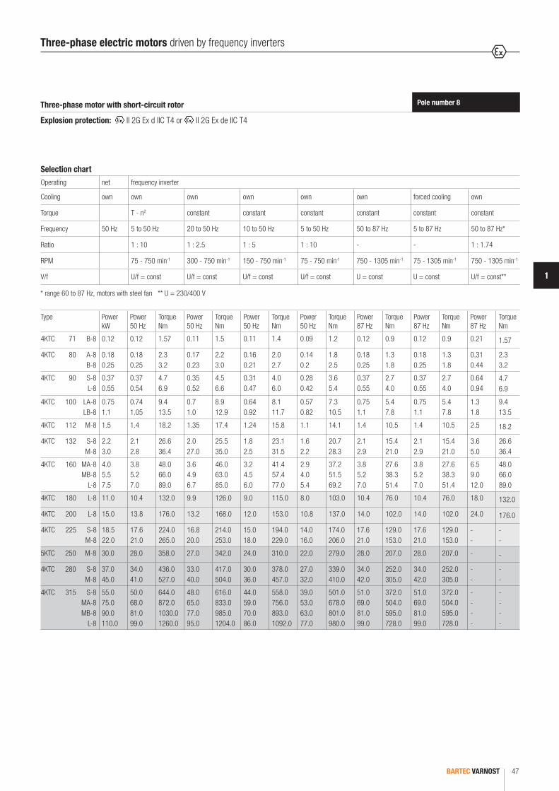
BARTEC VARNOST 47
1
Pole number 8Three-phase motor with short-circuit rotor
Explosion protection: II 2G Ex d IIC T4 or II 2G Ex de IIC T4
* range 60 to 87 Hz, motors with steel fan ** U = 230/400 V
Selection chart
Operating net frequency inverter
Cooling own own own own own own forced cooling own
Torque T - n2 constant constant constant constant constant constant
Frequency 50 Hz 5 to 50 Hz 20 to 50 Hz 10 to 50 Hz 5 to 50 Hz 50 to 87 Hz 5 to 87 Hz 50 to 87 Hz*
Ratio 1 : 10 1 : 2.5 1 : 5 1 : 10 - - 1 : 1.74
RPM 75 - 750 min-1 300 - 750 min-1 150 - 750 min-1 75 - 750 min-1 750 - 1305 min-1 75 - 1305 min-1 750 - 1305 min-1
V/f U/f = const U/f = const U/f = const U/f = const U = const U = const U/f = const**
Type PowerkW
Power50 Hz
TorqueNm
Power50 Hz
TorqueNm
Power50 Hz
TorqueNm
Power50 Hz
TorqueNm
Power87 Hz
TorqueNm
Power87 Hz
TorqueNm
Power87 Hz
Torque Nm
4KTC 71 B-8 0.12 0.12 1.57 0.11 1.5 0.11 1.4 0.09 1.2 0.12 0.9 0.12 0.9 0.21 1.57
4KTC 80 A-8 B-8
0.18 0.25
0.18 0.25
2.3 3.2
0.17 0.23
2.2 3.0
0.16 0.21
2.0 2.7
0.14 0.2
1.8 2.5
0.18 0.25
1.3 1.8
0.18 0.25
1.3 1.8
0,31 0.44
2.3 3.2
4KTC 90 S-8 L-8
0.37 0.55
0.37 0.54
4.7 6.9
0.35 0.52
4.5 6.6
0.31 0.47
4.0 6.0
0.28 0.42
3.6 5.4
0.37 0.55
2.7 4.0
0.37 0.55
2.7 4.0
0.64 0.94
4.7 6.9
4KTC 100 LA-8 LB-8
0.75 1.1
0.74 1.05
9.4 13.5
0.7 1.0
8.9 12.9
0.64 0.92
8.1 11.7
0.57 0.82
7.3 10.5
0.75 1.1
5.4 7.8
0.75 1.1
5.4 7.8
1.3 1.8
9.4 13.5
4KTC 112 M-8 1.5 1.4 18.2 1.35 17.4 1.24 15.8 1.1 14.1 1.4 10.5 1.4 10.5 2.5 18.2
4KTC 132 S-8 M-8
2.2 3.0
2.1 2.8
26.6 36.4
2.0 27.0
25.5 35.0
1.8 2.5
23.1 31.5
1.6 2.2
20.7 28.3
2.1 2.9
15.4 21.0
2.1 2.9
15.4 21.0
3.6 5.0
26.6 36.4
4KTC 160 MA-8 MB-8
L-8
4.0 5.5 7.5
3.8 5.2 7.0
48.0 66.0 89.0
3.6 4.9 6.7
46.0 63.0 85.0
3.2 4.5 6.0
41.4 57.4 77.0
2.9 4.0 5.4
37.2 51.5 69.2
3.8 5.2 7.0
27.6 38.3 51.4
3.8 5.2 7.0
27.6 38.3 51.4
6.5 9.0 12.0
48.0 66.0 89.0
4KTC 180 L-8 11.0 10.4 132.0 9.9 126.0 9.0 115.0 8.0 103.0 10.4 76.0 10.4 76.0 18.0 132.0
4KTC 200 L-8 15.0 13.8 176.0 13.2 168.0 12.0 153.0 10.8 137.0 14.0 102.0 14.0 102.0 24.0 176.0
4KTC 225 S-8 M-8
18.5 22.0
17.6 21.0
224.0 265.0
16.8 20.0
214.0 253.0
15.0 18.0
194.0 229.0
14.0 16.0
174.0 206.0
17.6 21.0
129.0 153.0
17.6 21.0
129.0 153.0
- -
- -
5KTC 250 M-8 30.0 28.0 358.0 27.0 342.0 24.0 310.0 22.0 279.0 28.0 207.0 28.0 207.0 - -
4KTC 280 S-8 M-8
37.0 45.0
34.0 41.0
436.0 527.0
33.0 40.0
417.0 504.0
30.0 36.0
378.0 457.0
27.0 32.0
339.0 410.0
34.0 42.0
252.0 305.0
34.0 42.0
252.0 305.0
- -
- -
4KTC 315 S-8 MA-8 MB-8
L-8
55.0 75.0 90.0 110.0
50.0 68.0 81.0 99.0
644.0 872.0 1030.0 1260.0
48.0 65.0 77.0 95.0
616.0 833.0 985.0 1204.0
44.0 59.0 70.0 86.0
558.0 756.0 893.0 1092.0
39.0 53.0 63.0 77.0
501.0 678.0 801.0 980.0
51.0 69.0 81.0 99.0
372.0 504.0 595.0 728.0
51.0 69.0 81.0 99.0
372.0 504.0 595.0 728.0
- - - -
- - - -
Three-phase electric motors driven by frequency inverters

BARTEC VARNOST48
Dimensions Tolerance
A, B < 250 mm ± 0.75 mm
> 250 mm ... 500 mm ± 1.00 mm
> 500 mm ... 750 mm ± 1.50 mm
H > 50 mm ... 250 mm - 0.50 mm
> 250 mm ... 630 mm - 1.00 mm
C < 85 mm ± 1.00 mm
> 85 mm ... 130 mm ± 2.00 mm
> 130 mm ... 240 mm ± 3.00 mm
> 240 mm ... 500 mm ± 4.00 mm
M < 200 mm ± 0.25 mm
> 200 mm ... 500 mm ± 0.50 mm
> 500 mm ± 1.00 mm
K and S+ 3 % diameter
E < 30 mm - 0.20 mm
> 30 mm ... 110 mm - 0.30 mm
D < ø 50 mm
k 6
> ø 50 mm
m 6
N < 230 mm j 6
> 250 mm h 6
Mounting dimensions
The mounting dimensions allow the following tolerances:
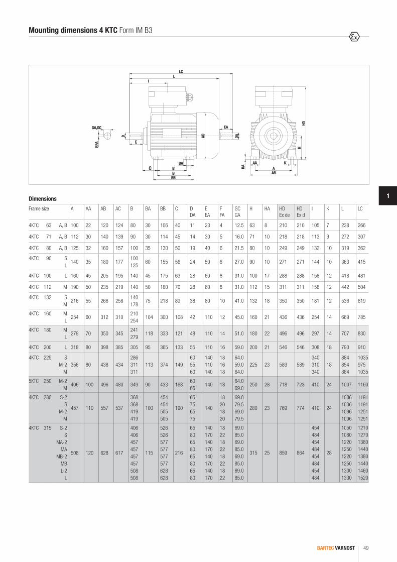
BARTEC VARNOST 49
1
HD
AA
AB
HA
DA
EA
AC
BA
BB
LCL
l
H
AK
BC
D
E
GA,GC
F,FA
B
Dimensions
Frame size A AA AB AC B BA BB C DDA
E EA
F FA
GC GA
H HA HD Ex de
HD Ex d
I K L LC
4KTC 63 A, B 100 22 120 124 80 30 106 40 11 23 4 12.5 63 8 210 210 105 7 238 266
4KTC 71 A, B 112 30 140 139 90 30 114 45 14 30 5 16.0 71 10 218 218 113 9 272 307
4KTC 80 A, B 125 32 160 157 100 35 130 50 19 40 6 21.5 80 10 249 249 132 10 319 362
4KTC 90 S L
140 35 180 177100 125
60 155 56 24 50 8 27.0 90 10 271 271 144 10 363 415
4KTC 100 L 160 45 205 195 140 45 175 63 28 60 8 31.0 100 17 288 288 158 12 418 481
4KTC 112 M 190 50 235 219 140 50 180 70 28 60 8 31.0 112 15 311 311 158 12 442 504
4KTC 132 S M
216 55 266 258140 178
75 218 89 38 80 10 41.0 132 18 350 350 181 12 536 619
4KTC 160 M L
254 60 312 310210 254
104 300 108 42 110 12 45.0 160 21 436 436 254 14 669 785
4KTC 180 M L
279 70 350 345241 279
118 333 121 48 110 14 51.0 180 22 496 496 297 14 707 830
4KTC 200 L 318 80 398 385 305 95 365 133 55 110 16 59.0 200 21 546 546 308 18 790 910
4KTC 225 S M-2
M356 80 438 434
286 311 311
113 374 14960 55 60
140 110 140
18 16 18
64.0 59.0 64.0
225 23 589 589340 310 340
18884 854 884
1035 975 1035
5KTC 250 M-2 M
406 100 496 480 349 90 433 16860 65
140 1864.0 69.0
250 28 718 723 410 24 1007 1160
4KTC 280 S-2 S
M-2 M
457 110 557 537
368 368 419 419
100
454 454 505 505
190
65 75 65 75
140
18 20 18 20
69.0 79.5 69.0 79.5
280 23 769 774 410 24
1036 1036 1096 1096
1191 1191 1251 1251
4KTC 315 S-2 S
MA-2 MA
MB-2 MB L-2
L
508 120 628 617
406 406 457 457 457 457 508 508
115
526 526 577 577 577 577 628 628
216
65 80 65 80 65 80 65 80
140 170 140 170 140 170 140 170
18 22 18 22 18 22 18 22
69.0 85.0 69.0 85.0 69.0 85.0 69.0 85.0
315 25 859 864
454 484 454 484 454 484 454 484
28
1050 1080 1220 1250 1220 1250 1300 1330
1210 1270 1380 1440 1380 1440 1460 1520
Mounting dimensions 4 KTC Form IM B3

BARTEC VARNOST50
lL
LC
EA
DAAC
45°
22.5°
GA,GC
F,FA
HBS
M
T
P DN
E
LA
HB
S
M
Dimensions
Frame size Flange AC D DA
E EA
F FA
GC GA
HB Ex de
HB Ex d
I L LA LC M N P S No. of fixing holes
T
4KTC 63 A, B F 115-I 124 11 23 4 12.5 147 147 105 238 8 266 115 95 140 9 4 3.0
4KTC 71 A, B F 130-I 139 14 30 5 16.0 147 147 113 272 10 307 130 110 160 9 4 3.5
4KTC 80 A, B F 165-I 157 19 40 6 21.5 169 169 132 319 10 362 165 130 200 12 4 3.5
4KTC 90 S, L F 165-I 177 24 50 8 27.0 181 181 144 363 10 415 165 130 200 12 4 3.5
4KTC 100 L F 215-I 195 28 60 8 31.0 188 188 158 418 11 481 215 180 250 14 4 4.0
4KTC 112 M F 215-I 219 28 60 8 31.0 199 199 158 442 11 504 215 180 250 14 4 4.0
4KTC 132 S, M F 265-I 258 38 80 10 41.0 218 218 181 536 12 619 265 230 300 14 4 4.0
4KTC 160 M, L F 300-I 310 42 110 12 45.0 276 276 254 669 15 785 300 250 350 18 4 5.0
4KTC 180 M, L F 300-I 345 48 110 14 51.0 316 316 297 707 15 830 300 250 350 18 4 5.0
4KTC 200 L F 350-I 385 55 110 16 59.0 346 346 308 790 18 910 350 300 400 18 4 5.0
4KTC 225 S M-2
MF 400-I 434
60 55 60
140 110 140
18 16 18
64.0 59.0 64.0
364 364340 310 340
884 854 884
181035 975 1035
400 350 450 18 8 5.0
5KTC 250 M-2 M
F 500-I 48060 65
140 1864.0 69.0
468 473 410 1007 18 1160 500 450 550 19 8 5.0
4KTC 280 S-2 S
M-2 M
F 500-I 537
65 75 65 75
140
18 20 18 20
69.0 79.5 69.0 79.5
489 494 410
1036 1036 1096 1096
18
1191 1191 1251 1251
500 450 550 19 8 5.0
4KTC 315 S-2 S
MA-2 MA
MB-2 MB L-2
L
F 600-I 617
65 80 65 80 65 80 65 80
140 170 140 170 140 170 140 170
18 22 18 22 18 22 18 22
69.0 85.5 69.0 85.5 69.0 85.5 69.0 85.5
544 549
454 484 454 484 454 484 454 484
1050 1080 1220 1250 1220 1250 1300 1330
22
1210 1270 1380 1440 1380 1440 1460 1520
600 550 660 24 8 6.0
Mounting dimensions 4 KTC Form IM B5 (V1)

BARTEC VARNOST 51
1
lL
LC
EA
DAAC
45°
22.5°
HA
AA
AB
HA
AA
AB
HD HD
BA
BB
GA,GC
F,FA
S
M
T
P DN
E
LA
S
M
63 to 200 225 to 315
A
K
H
A
K
H
BC
B
Dimensions
Frame size Flange A AA AB AC B BA BB C D DA
E EA
F FA
GC GA
H HA HD Ex de
HD Ex d
I K L LA LC M N P S No. of fixing holes
4KTC 63 A, B F 115-I 100 22 120 124 80 30 106 40 11 23 4 12.5 63 8 210 210 105 7 238 8 266 115 95 140 9 4
4KTC 71 A, B F 130-I 112 30 140 139 90 30 114 45 14 30 5 16.0 71 10 218 218 113 9 272 10 307 130 110 160 9 4
4KTC 80 A, B F 165-I 125 32 160 157 100 35 130 50 19 40 6 21.5 80 10 249 249 132 10 319 10 362 165 130 200 12 4
4KTC 90 S L
F 165-I 140 35 180 177100 125
60 155 56 24 50 8 27.0 90 10 271 271 144 10 363 10 415 165 130 200 12 4
4KTC 100 L F 215-I 160 45 205 195 140 45 175 63 28 60 8 31.0 100 17 288 288 158 12 418 11 481 215 180 250 14 4
4KTC 112 M F 215-I 190 50 235 219 140 50 180 70 28 60 8 31.0 112 15 311 311 158 12 442 11 504 215 180 250 14 4
4KTC 132 S M
F 265-I 216 55 266 258140 178
75 218 89 38 80 10 41.0 132 18 350 350 181 12 536 12 619 265 230 300 14 4
4KTC 160 M L
F 300-I 254 60 312 310210 254
104 300 108 42 110 12 45.0 160 21 436 436 254 14 669 15 785 300 250 350 18 4
4KTC 180 M-2 L
F 300-I 279 70 350 345241 279
118 333 121 48 110 14 51.0 180 22 496 496 297 14 707 15 830 300 250 350 18 4
4KTC 200 L F 350-I 318 80 398 385 305 95 365 133 55 110 16 59.0 200 21 546 546 308 18 790 18 910 350 300 400 18 4
4KTC 225 S M-2
MF 400-I 356 80 438 433
286 311 311
113 374 14960 55 60
140 110 140
18 16 18
64.0 59.0 64.0
225 23 589 589340 310 340
18884 854 884
181035 975 1035
400 350 450 18 8
5KTC 250 M-2 M
F 500-I 406 100 496 480 349 90 433 16860 65
140 1864.0 69.0
250 28 718 723 410 24 1007 18 1160 500 450 550 19 8
4KTC 280 S-2 S
M-2 M
F 500-I 457 110 557 537
368 368 419 419
100
454 454 505 505
190
65 75 65 75
140
18 20 18 20
69.0 79.5 69.0 79.5
280 23 769 774 410 24
1036 1036 1096 1096
18
1191 1191 1251 1251
500 450 550 19 8
4KTC 315 S-2 S
MA-2 MA
MB-2 MB L-2
L
F 600-I 508 120 628 617
406 406 457 457 457 457 508 508
115
526 526 577 577 577 577 628 628
216
65 80 65 80 65 80 65 80
140 170 140 170 140 170 140
170
18 22 18 22 18 22 18 22
69.0 85.5 69.0 85.5 69.0 85.5 69.0
85.5
315 25 859 864
454 484 454 484 454 484 454
484
28
1050 1080 1220 1250 1220 1250 1300 1330
22
1210 1270 1380 1440 1380 1440 1460
1520
600 550 660 24 8
63 to 200 225 to 315
Mounting dimensions 4 KTC Form IM B3/B5
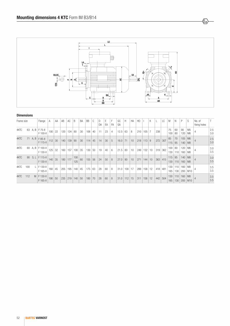
BARTEC VARNOST52
45°
ABA
AA K
HDH
NP
LAT
EA
DA
LLC
I
AC
C
BB
D
E
S
BB
BA
GA,GC
F,FA
Dimensions
Frame size Flange A AA AB AC B BA BB C D DA
E EA
F FA
GC GA
H HA HD I K L LC M N P S No. of fixing holes
T
4KTC 63 A, B F 75-II F 100-II
100 22 120 124 80 30 106 40 11 23 4 12.5 63 8 210 105 7 23875 100
60 80
90 120
M5 M6
42.5 3.0
4KTC 71 A, B F 85-II F 115-II
112 30 140 139 90 30 114 45 14 30 5 16.0 71 10 218 113 9 272 30785 115
70 95
105 140
M6 M8
42.5 3.0
4KTC 80 A, B F 100-II F 130-II
125 32 160 157 100 35 130 50 19 40 6 21.5 80 10 249 132 10 319 362100 130
80 110
120 160
M6 M8
43.0 3.5
4KTC 90 S, L F 115-II F 130-II
140 35 180 177100 125
60 155 56 24 50 8 27.0 90 10 271 144 10 363 415115 130
95 110
140 160
M8 M8
43.0 3.5
4KTC 100 L F 130-II F 165-II
160 45 205 195 140 45 175 63 28 60 8 31.0 100 17 288 158 12 418 481130 165
110 130
160 200
M8 M10
43.5 3.5
4KTC 112 M F 130-II F 165-II
190 50 235 219 140 50 180 70 28 60 8 31.0 112 15 311 158 12 442 504130 165
110 130
160 200
M8 M10
43.5 3.5
Mounting dimensions 4 KTC Form IM B3/B14
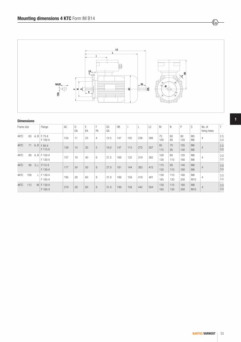
BARTEC VARNOST 53
1
M
S
E
D AC
I
LCL
DA
EA
TLA
P N
HB
GA,GC
F,FA
Dimensions
Frame size Flange AC D DA
E EA
F FA
GC GA
HB I L LC M N P S No. of fixing holes
T
4KTC 63 A, B F 75-II F 100-II
124 11 23 4 12.5 147 105 238 26675 100
60 80
90 120
M5 M6
42.5 3.0
4KTC 71 A, B F 85-II F 115-II
139 14 30 5 16.0 147 113 272 30785 115
70 95
105 140
M6 M8
42.5 3.0
4KTC 80 A, B F 100-II F 130-II
157 19 40 6 21.5 169 132 319 362100 130
80 110
120 160
M6 M8
43.0 3.5
4KTC 90 S, L F115-II F 130-II
177 24 50 8 27.0 181 144 363 415115 130
95 110
140 160
M8 M8
43.0 3.5
4KTC 100 L F 130-II F 165-II
195 28 60 8 31.0 188 158 418 481130 165
110 130
160 200
M8 M10
43.5 3.5
4KTC 112 M F 130-II F 165-II
219 28 60 8 31.0 199 158 442 504130 165
110 130
160 200
M8 M10
43.5 3.5
Mounting dimensions 4 KTC Form IM B14

BARTEC VARNOST54
HB HB
ØD
E LA
T
LB
C BØK
A
AB
H
S
LM
L
ØN
ØM
ØP
B
HM
�KA
AB
H
S HM
Mounting dimensions Special execution Ex brake
Dimensions
Frame size Brake frame size
A AB B C D E H HB HM ∅ K LA LB LM L ∅ M ∅ N ∅ P S No. of fixing holes
4KTC 63 A, B 63 100 120 80 40 11 23 63 185 147 7 10 168 215 383 115 95 140 9 4
4KTC 71 A, B 71 112 140 90 45 14 30 71 185 147 9 10 175 242 417 130 110 160 9 4
4KTC 80 A, B 80 125 160 100 50 19 40 80 215 169 10 12 238 279 517 165 130 200 11 4
4KTC 90 S L
90 140 180100 125
56 24 50 90 215 181 10 12 248 313 651 165 130 200 11 4
4KTC 100 L 100/112 160 205 140 63 28 60 100 240 188 12 14 276 358 634 215 180 250 14 4
4KTC 112 M 100/112 190 235 140 70 28 60 112 240 199 12 14 276 382 658 215 180 250 14 4
4KTC 132 S M
132 216 266140 178
89 38 80 132 265 218 12 18 322 456 778 265 230 300 14 4
4KTC 160 M L
160 254 312210 254
108 42 110 160 265 276 14 18 352 559 911 300 250 350 16 4
4KTC 180 M L
180 279 350241 279
121 48 110 180 282 316 14 21 410 597 1007 300 250 350 18 4
4KTC 200 L 200 318 398 305 133 55 110 200 282 346 18 21 410 680 1090 350 300 400 18 4
4KTC 225 S M2
M225 356 436
286 311 311
14960 55 60
140 110 140
225 282 364 18 21 440 744 1184 300 400 450 18 8
5KTC 250 M2 250 406 496 349 16860 65
140 250 328 473 24 26 450 867 1317 500 450 550 18 8
4KTC 280 S2 S
M2 M
280 457 557
368 368 419 419
190
65 75 65 75
140 280 328 494 24 26 450
896 896 956 956
1346 1346 1406 1406
500 450 550 18 8
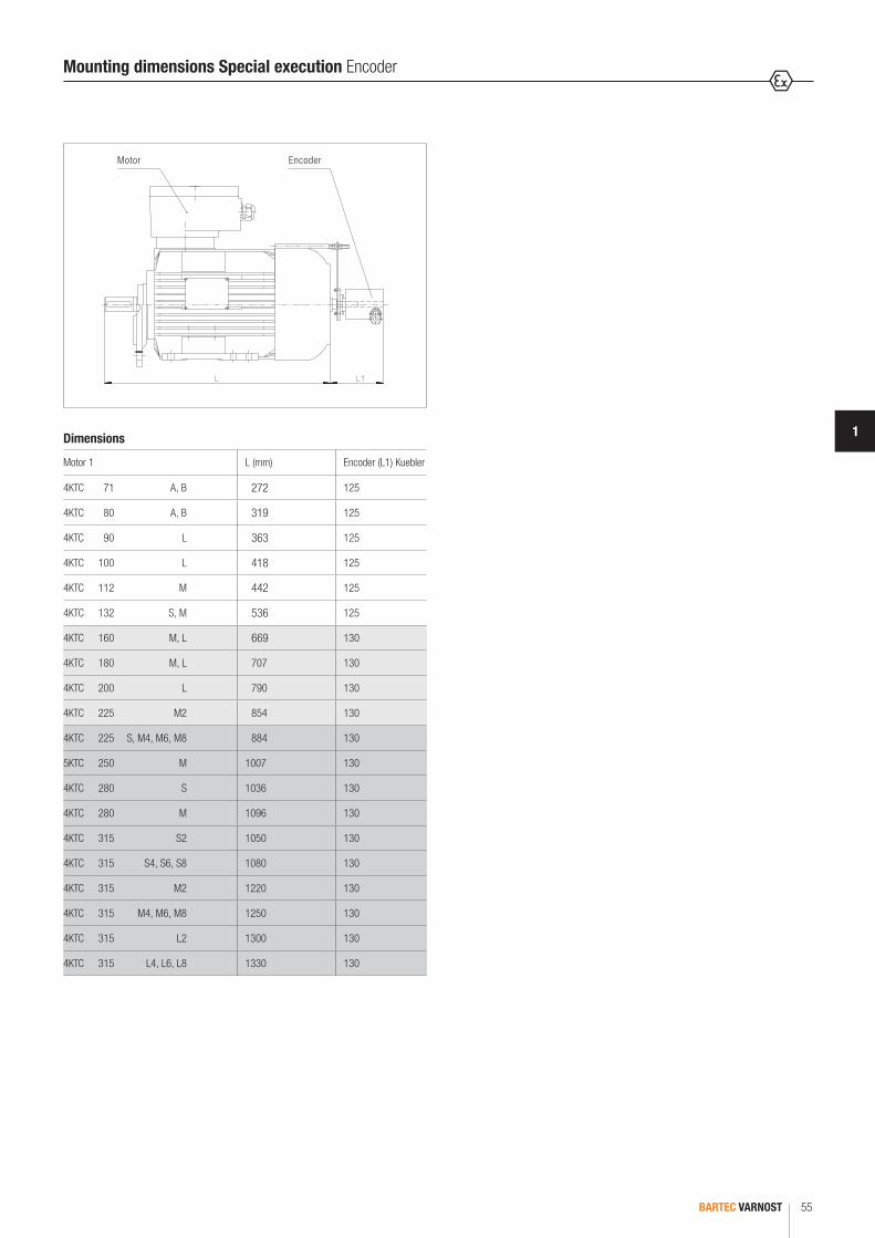
BARTEC VARNOST 55
1
Motor Encoder
Mounting dimensions Special execution Encoder
Dimensions
Motor 1 L (mm) Encoder (L1) Kuebler
4KTC 71 A, B 272 125
4KTC 80 A, B 319 125
4KTC 90 L 363 125
4KTC 100 L 418 125
4KTC 112 M 442 125
4KTC 132 S, M 536 125
4KTC 160 M, L 669 130
4KTC 180 M, L 707 130
4KTC 200 L 790 130
4KTC 225 M2 854 130
4KTC 225 S, M4, M6, M8 884 130
5KTC 250 M 1007 130
4KTC 280 S 1036 130
4KTC 280 M 1096 130
4KTC 315 S2 1050 130
4KTC 315 S4, S6, S8 1080 130
4KTC 315 M2 1220 130
4KTC 315 M4, M6, M8 1250 130
4KTC 315 L2 1300 130
4KTC 315 L4, L6, L8 1330 130
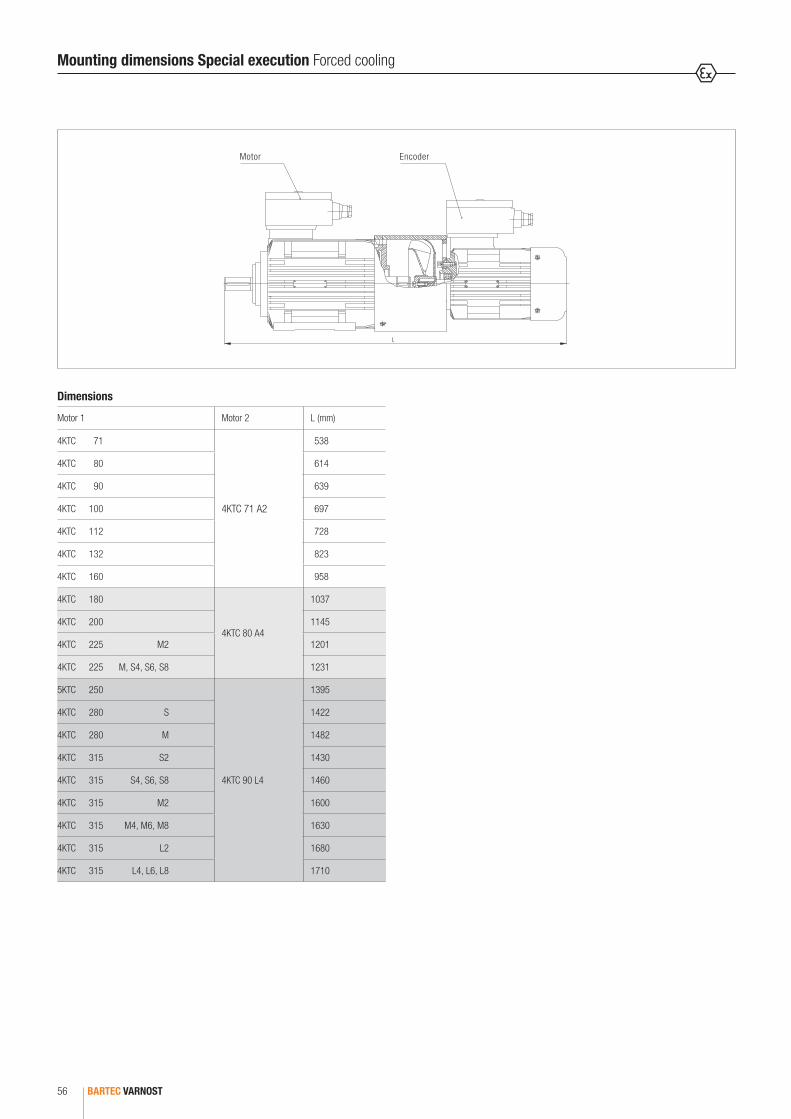
BARTEC VARNOST56
Motor Encoder
Mounting dimensions Special execution Forced cooling
Dimensions
Motor 1 Motor 2 L (mm)
4KTC 71
4KTC 71 A2
538
4KTC 80 614
4KTC 90 639
4KTC 100 697
4KTC 112 728
4KTC 132 823
4KTC 160 958
4KTC 180 4KTC 80 A4
1037
4KTC 200 1145
4KTC 225 M2 1201
4KTC 225 M, S4, S6, S8 1231
5KTC 250
4KTC 90 L4
1395
4KTC 280 S 1422
4KTC 280 M 1482
4KTC 315 S2 1430
4KTC 315 S4, S6, S8 1460
4KTC 315 M2 1600
4KTC 315 M4, M6, M8 1630
4KTC 315 L2 1680
4KTC 315 L4, L6, L8 1710
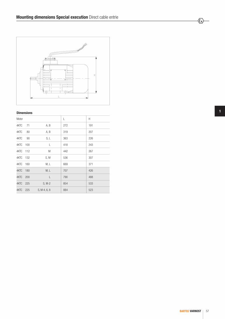
BARTEC VARNOST 57
1
Mounting dimensions Special execution Direct cable entrie
Dimensions
Motor L H
4KTC 71 A, B 272 191
4KTC 80 A, B 319 207
4KTC 90 S, L 363 226
4KTC 100 L 418 243
4KTC 112 M 442 267
4KTC 132 S, M 536 307
4KTC 160 M, L 669 371
4KTC 180 M, L 707 426
4KTC 200 L 790 488
4KTC 225 S, M-2 854 533
4KTC 225 S, M-4, 6, 8 884 523
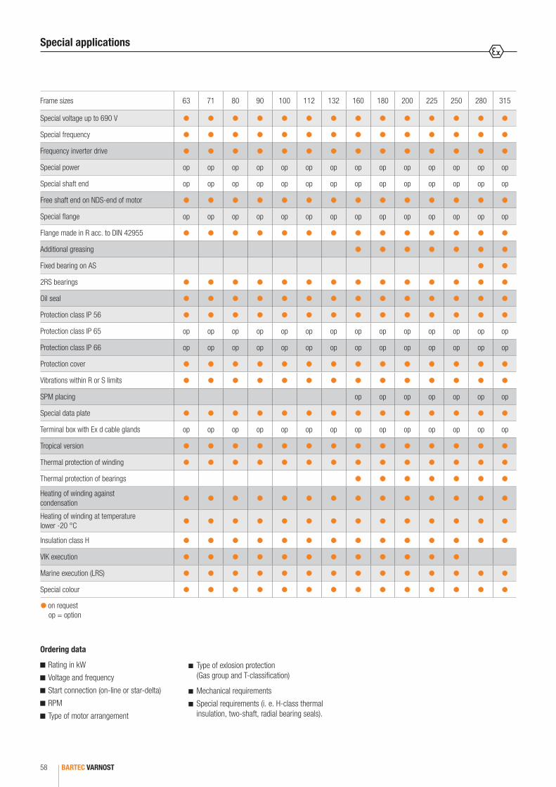
BARTEC VARNOST58
Ordering data
Rating in kW
Voltage and frequency
Start connection (on-line or star-delta)
RPM
Type of motor arrangement
Type of exlosion protection (Gas group and T-classification)
Mechanical requirements
Special requirements (i. e. H-class thermal insulation, two-shaft, radial bearing seals).
Frame sizes 63 71 80 90 100 112 132 160 180 200 225 250 280 315
Special voltage up to 690 V
Special frequency
Frequency inverter drive
Special power op op op op op op op op op op op op op op
Special shaft end op op op op op op op op op op op op op op
Free shaft end on NDS-end of motor
Special flange op op op op op op op op op op op op op op
Flange made in R acc. to DIN 42955
Additional greasing
Fixed bearing on AS
2RS bearings
Oil seal
Protection class IP 56
Protection class IP 65 op op op op op op op op op op op op op op
Protection class IP 66 op op op op op op op op op op op op op op
Protection cover
Vibrations within R or S limits
SPM placing op op op op op op op
Special data plate
Terminal box with Ex d cable glands op op op op op op op op op op op op op op
Tropical version
Thermal protection of winding
Thermal protection of bearings
Heating of winding against condensation
Heating of winding at temperature lower -20 °C
Insulation class H
VIK execution
Marine execution (LRS)
Special colour
on request op = option
Special applications

FLAMEPROOF BRAKE MOTORS, SERIES BM 4KTC


FLAMEPROOF BRAKE MOTORS, SERIES BM 4KTCGeneral performance
BM 4KTC 2 pole and 4 pole motors 50 Hz
62 - 63
Dimensions form IM B3 63
Dimensions form IM B5 V1 and IM B3/B5 64
Dimensions form IM B3/B14 and IM B14 65
Quality 66
CONTENTS

BARTEC VARNOST62
Our flameproof motors type 4KTC can be supplied with flameproof spring loaded brakes. Brakes type 4BM are always attached on NDE side of motor. Cooling fan is installed on back side of brake which provide high efficiency cooling of brake as well as motor. The electrical connection is made in a sep-arate terminal box on a brake. Techical specification for motors series 4KTC is available in our general catalogues of flameproof motors.
Features
Frame size 71-132
First quality class components
Robust design for heavy working conditions
Large terminal box Ex d or Ex de
Duty type S1-S9
Frequency drive from 48 up to 6000 rpm
50 Hz and 60 Hz
PTC or Pt100 or PTO thermal protection
Highest explosion protection for gas and dust
For Zone 1, 2 and Zone 21, 22
Up to IP 66
Ambient temperature from -50 °C up to +85 °C
ATEX and IECEx certificates
Flameproof brake motors 4KTC - General performance
Explosion protection
Marking ATEX
Certification
II 2G Ex d IIC T4 toT6 Gb II 2G Ex de IIC T4 to T6 Gb II 2D Ex tb IIIC T85 °C to T135 °C Db
BVS 12 ATEX E 044 X, IECEx BVS 14.0033X
Technical data
Protection class up to IP 66
Frequency 50 Hz or 60 Hz
Ambient temperature -50 °C to +85 °C
Insulatin class F standard, H on request
Duty type S1 to S9
Material grey cast iron
Standard colour RAL 5010, other colours on request
General performance 2 pole motors 50 Hz
Motor with brake type Nmmin./max.
VoltageAC
WAC (1 ph)
Max. RPM Starts/h max.
Braking timems
Weight kg
S1 S9 B3 B5 B14
BM 4KTC 71 A-2/085/6.5 230 22
2800 5600 290090 27 29 28
BM 4KTC 71 B-2/08 2800 5600 2450
BM 4KTC 80 A-2/1010/13 230 28
2780 5560 1900145 37 39 38
BM 4KTC 80 B-2/10 2800 5600 1600
BM 4KTC 90 S-2/1320/26 230 34
2840 5680 1200280 49 51 50
BM 4KTC 90 L-2/13 2820 5640 1050
BM 4KTC 100 L-2/15 40/52 230 42 2820 5640 630 225 63 67 66
BM 4KTC 112 M-2/17 60/78 230 50 2840 5680 270 290 81 87 86
BM 4KTC 132 SA-2/20100/130 230 76
2860 5720 250420 126 132 131
BM 4KTC 132 SB-2/20 2860 5720 250
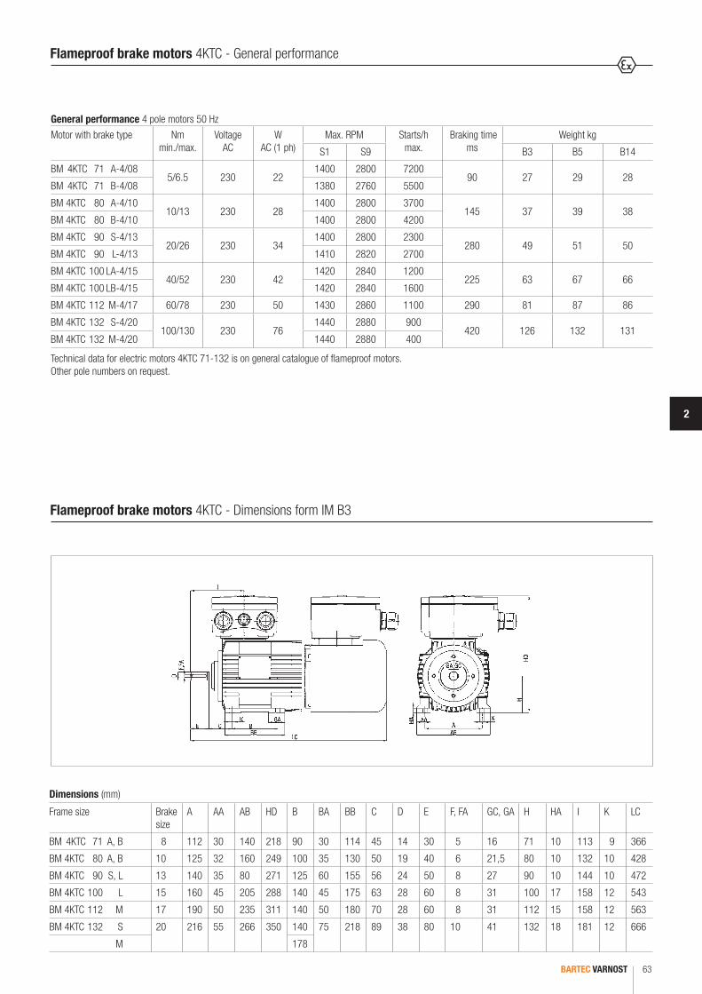
2
BARTEC VARNOST 63
Dimensions (mm)
Frame size Brake size
A AA AB HD B BA BB C D E F, FA GC, GA H HA I K LC
BM 4KTC 71 A, B 8 112 30 140 218 90 30 114 45 14 30 5 16 71 10 113 9 366
BM 4KTC 80 A, B 10 125 32 160 249 100 35 130 50 19 40 6 21,5 80 10 132 10 428
BM 4KTC 90 S, L 13 140 35 80 271 125 60 155 56 24 50 8 27 90 10 144 10 472
BM 4KTC 100 L 15 160 45 205 288 140 45 175 63 28 60 8 31 100 17 158 12 543
BM 4KTC 112 M 17 190 50 235 311 140 50 180 70 28 60 8 31 112 15 158 12 563
BM 4KTC 132 S 20 216 55 266 350 140 75 218 89 38 80 10 41 132 18 181 12 666
M 178
General performance 4 pole motors 50 HzMotor with brake type Nm
min./max.Voltage
ACW
AC (1 ph)Max. RPM Starts/h
max. Braking time
msWeight kg
S1 S9 B3 B5 B14
BM 4KTC 71 A-4/085/6.5 230 22
1400 2800 720090 27 29 28
BM 4KTC 71 B-4/08 1380 2760 5500
BM 4KTC 80 A-4/1010/13 230 28
1400 2800 3700145 37 39 38
BM 4KTC 80 B-4/10 1400 2800 4200
BM 4KTC 90 S-4/1320/26 230 34
1400 2800 2300280 49 51 50
BM 4KTC 90 L-4/13 1410 2820 2700
BM 4KTC 100 LA-4/1540/52 230 42
1420 2840 1200225 63 67 66
BM 4KTC 100 LB-4/15 1420 2840 1600
BM 4KTC 112 M-4/17 60/78 230 50 1430 2860 1100 290 81 87 86
BM 4KTC 132 S-4/20100/130 230 76
1440 2880 900420 126 132 131
BM 4KTC 132 M-4/20 1440 2880 400
Technical data for electric motors 4KTC 71-132 is on general catalogue of flameproof motors.Other pole numbers on request.
Flameproof brake motors 4KTC - General performance
Flameproof brake motors 4KTC - Dimensions form IM B3

BARTEC VARNOST64
Flameproof brake motors 4KTC - Dimensions form IM B5 V1 and IM B3/B5
Dimensions IM B5 V1
Dimensions IM B3/B5
Dimensions (mm)
Frame size Brake size
Flange HB D E F, FA GC, GA
I LA LC M N P S No. of holes S T
BM 4KTC 71 A, B 8 F 130-I 147 14 30 5 16 113 10 366 130 110 160 9
4
3.5
BM 4KTC 80 A, B 10 F 165-I 169 19 40 6 21.5 132 10 428 165 130 200 12 3.5
BM 4KTC 90 S, L 13 F 165-I 181 24 50 8 27 144 10 472 165 130 200 12 3.5
BM 4KTC 100 L 15 F 215-I 188 28 60 8 31 158 11 543 215 180 250 14 4
BM 4KTC 112 M 17 F 215-I 199 28 60 8 31 158 11 563 215 180 250 14 4
BM 4KTC 132 S, M 20 F 265-I 218 38 80 10 41 181 15 666 265 230 300 14 4
Dimensions (mm)Frame size Brake
sizeFlange A AA AB HD B BA BB C D E F,
FAGC,GA
H HA I K LC M N P S No. of holes S
BM 4KTC 71 A, B 8 F 130-I 112 30 140 218 90 30 114 45 14 30 5 16 71 10 113 9 366 130 110 160 9
4
BM 4KTC 80 A, B 10 F 165-I 125 32 160 249 100 35 130 50 19 40 6 21.5 80 10 132 10 428 165 130 200 12
BM 4KTC 90 S, L 13 F 165-I 140 35 80 271 125 60 155 56 24 50 8 27 90 10 144 10 472 165 130 200 12
BM 4KTC 100 L 15 F 215-I 160 45 205 288 140 45 175 63 28 60 8 31 100 17 158 12 543 215 180 250 14
BM 4KTC 112 M 17 F 215-I 190 50 235 311 140 50 180 70 28 60 8 31 112 15 158 12 563 215 180 250 14
BM 4KTC 132 S 20 F 265-I 216 55 266 350 140 75 218 89 38 80 10 41 132 18 181 12 666 265 230 300 14
M 178

2
BARTEC VARNOST 65
Dimensions IM B14
Dimensions IM B3/B14
Dimensions (mm)Frame size Brake size Flange D E F, FA GC, GA HB I LC M N P S No. of holes S T
BM 4KTC 71 A, B 8F 85-II
14 30 5 16 147 113 36685 70 105 M6
4
2.5
F 115-II 115 95 140 M8 3
BM 4KTC A, B 10F 100-II
19 40 6 21.5 169 132 428100 80 120 M6 2.5
F 130-II 130 110 160 M8 3
BM 4KTC 90 L, S 13F 115-II
24 50 8 27 181 144 472115 95 140 M8 3
F 130-II 130 110 160 M8 3.5
BM 4KTC 100 L 15F 130-II
28 60 8 31 188 158 543130 110 160 M8 3.5
F 165-II 165 130 200 M10 3.5
BM 4KTC 112 M 17F 130-II
28 60 8 31 199 158 563130 110 160 M8 3.5
F 165-II 165 130 200 M10 3.5
Dimensions (mm)
Frame size Brake size
Flange A AA AB HD B BA BB C D E F, FA
GC,GA
H I LC M N P S No. of holes S
T
BM 4KTC 71 A, B 8F 85-II
112 30 140 218 90 30 114 45 14 30 5 16 71 113 36685 70 105 M6
4
2.5
F 115-II 115 95 140 M8 3
BM 4KTC A, B 10F 100-II
125 32 160 249 100 35 130 50 19 40 6 21.5 80 132 428100 80 120 M6 2.5
F 130-II 130 110 160 M8 3
BM 4KTC 90 l, S 13F 115-II
140 35 180 271100
60 155 56 24 50 8 27 90 144 472115 95 140 M8 3
F 130-II 125 130 110 160 M8 3.5
BM 4KTC 100 L 15F 130-II
160 45 205 288 140 45 175 63 28 60 8 31 100 158 543130 110 160 M8 3.5
F 165-II 165 130 200 M10 3.5
BM 4KTC 112 M 17F 130-II
190 50 235 311 140 50 180 70 28 60 8 31 112 158 563130 110 160 M8 3.5
F 165-II 165 130 200 M10 3.5
Flameproof brake motors 4KTC - Dimensions form IM B3/B14 and IM B14

BARTEC VARNOST66
Quality
The quality of our products and services is our primary concern. The reliability and high technical level of our systems and components have been confirmed by
the internationally accredited test institutes which have awarded us numerous certificates.
With the help of the ISO 9001:2000 certificate the system of quality BARTEC VARNOST is recognizable throughout the world and assures quality from the devel-
opment to the delivery of a product to the customer.
SIQ 11 ATEX Q 220-2
ISO 9001
ISO 14001
OHSAS 18001

NEMA EXPLOSION-PROOF MOTORS, SERIES 4KTU

03-0330-0407-10/2017-BAT-236279/1BARTEC68

03-0330-0407-10/2017-BAT-236279/1 BARTEC 69
NORTH AMERICA CERTIFICATION 70
INTRODUCTION 71
CONSTRUCTION 71 - 95
Basic design 71
Bearings 72
Shaft ends 73
Allowable radial force 73
Maximum axial loads 74
Terminal box 74 - 75
Degree of protection and painting 76
Mountings form, Explosion protection and certificates 77 - 78
Power, voltage and service factor 78
Windings 79 - 80
Duty cycles 80 - 81
Direct cable entries 82
Motors with brakes 82
Motors with encoders 82
Forced cooling 82
Electrical data for variable speed motors 83
Variable speed drive application 83
Electrical data for single speed motors HIGH EFFICIENCY 84 - 85
Electrical data for single speed motors PREMIUM EFFICIENCY 86 - 87
Motor dimensions 88 - 95
SPECIAL APPLICATIONS 96
CONTENTS
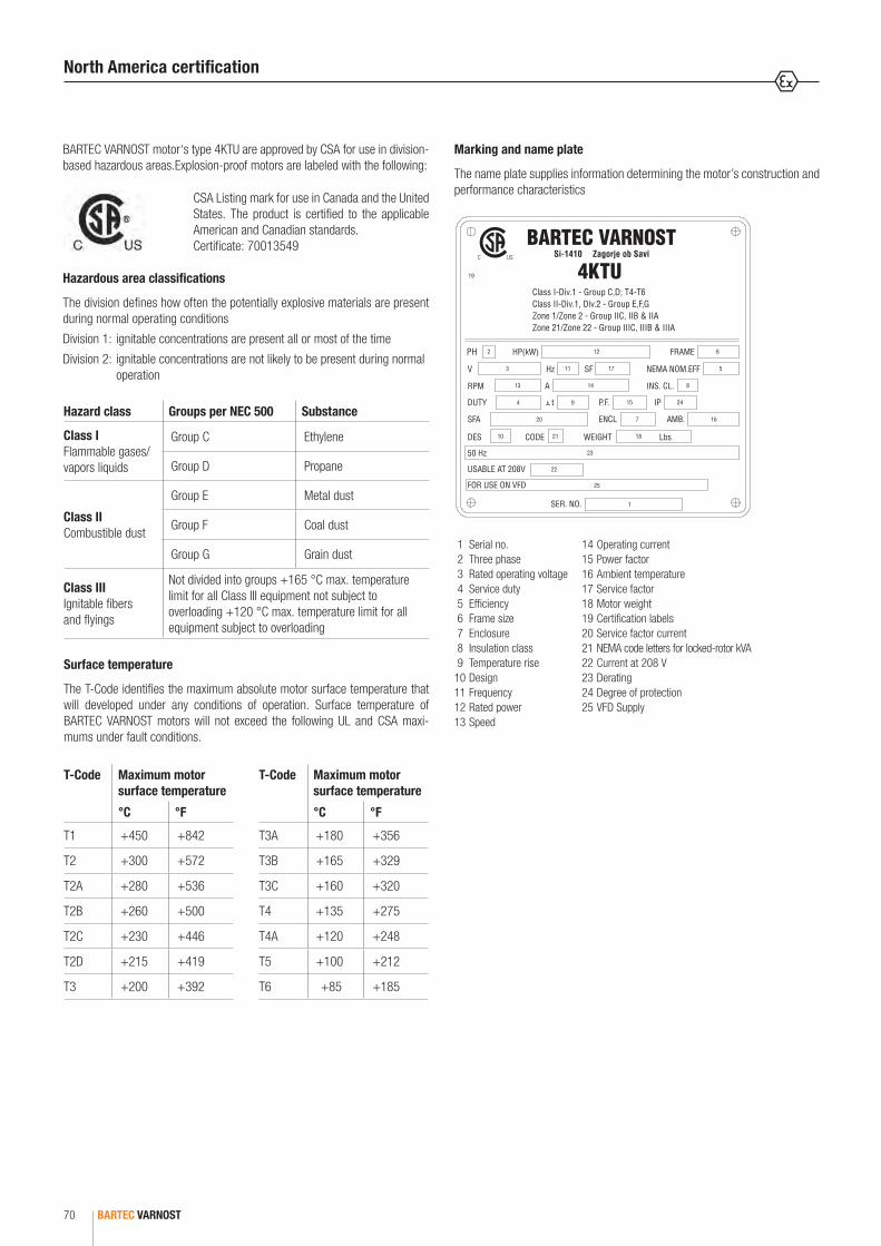
BARTEC VARNOST70
BARTEC VARNOST motor‘s type 4KTU are approved by CSA for use in division-based hazardous areas.Explosion-proof motors are labeled with the following:
CSA Listing mark for use in Canada and the United States. The product is certified to the applicable American and Canadian standards.Certificate: 70013549
Hazardous area classifications
The division defines how often the potentially explosive materials are present during normal operating conditions
Division 1: ignitable concentrations are present all or most of the time
Division 2: ignitable concentrations are not likely to be present during normal operation
Surface temperature
The T-Code identifies the maximum absolute motor surface temperature that will developed under any conditions of operation. Surface temperature of BARTEC VARNOST motors will not exceed the following UL and CSA maxi-mums under fault conditions.
Marking and name plate
The name plate supplies information determining the motor’s construction and performance characteristics
1 Serial no. 2 Three phase 3 Rated operating voltage 4 Service duty 5 Efficiency 6 Frame size 7 Enclosure 8 Insulation class 9 Temperature rise10 Design11 Frequency12 Rated power 13 Speed
C US
North America certification
Hazard class Groups per NEC 500 Substance
Class IFlammable gases/vapors liquids
Group C Ethylene
Group D Propane
Class IICombustible dust
Group E Metal dust
Group F Coal dust
Group G Grain dust
Class IIIIgnitable fibers and flyings
Not divided into groups +165 °C max. temperature limit for all Class III equipment not subject to overloading +120 °C max. temperature limit for all equipment subject to overloading
T-Code Maximum motor surface temperature
°C °F
T1 +450 +842
T2 +300 +572
T2A +280 +536
T2B +260 +500
T2C +230 +446
T2D +215 +419
T3 +200 +392
T-Code Maximum motor surface temperature
°C °F
T3A +180 +356
T3B +165 +329
T3C +160 +320
T4 +135 +275
T4A +120 +248
T5 +100 +212
T6 +85 +185
14 Operating current 15 Power factor 16 Ambient temperature 17 Service factor 18 Motor weight 19 Certification labels20 Service factor current21 NEMA code letters for locked-rotor kVA22 Current at 208 V23 Derating24 Degree of protection 25 VFD Supply

3
BARTEC VARNOST 71
INTRODUCTION
Flame proof AC electric motors are used in hazardous locations or potentially hazardous environments where concentrations of combustible gases, vapors and or dust are present or present some of the time. Motors type 4KTU can be manufactured to NEMA frame size 143 to 365 as well as IEC frame size 71 to 255.
4KTU motors are three-phase, asynchronous electric motors with short circuit rotors explosion-protected according to the:
• “Flame-proof enclosure” for the motor housing and “Increased safety” for terminal box according to UL 60079-1/CSA C22.2 60079-1, UL 60079-7/CSA C22.2 60079-7 and CSA C22.2 No. 30 (Class I, Zone I)
• “Flame-proof enclosure” for the motor housing and “Flame-proof enclosure” for terminal box according to UL 60079-1/CSA C22.2 60079-1 and CSA C22.2 No. 30 (Class I, Zone I)
• Dust Ignition Proof “DIP” (Class II, Division 1) according to CSA C22.2 No. 25
• Dust protected “NI” (Class II, Division 2) according to CSA C22.2 No. 25
• Protection by Enclosure “Ex tb” (Class II, Zone 21) according to UL 60079-31/CSA C22.2 No. 60079-31
The standard electric motor is suitable for T4 to T6 temperature classes or the maximum +257 ˚F to +185 ˚F/+125 ˚C to +85 ˚C surface temperatures of equipment.
Type 4KTU motors are available in a high efficiency class.
The type 4KTU motors are totally enclosed and fan-cooled (TEFC), as per NEMA MG-1 Part 6. Non-ventilated versions (TENV), air over (TEAO) and with forced ventilation (TEFV) are available.
Basic design
Frame size IEC 71
Frame size IEC 80-132; NEMA 143/5 – 213/5
Introduction/Construction Basic design
Materials
Frame size
Stator Shield Terminal box
Flange Fan cover
Fan
Frame Feet Material
143T
Cast
iron
Cast
iron
scr
ew o
n fe
et
Cast
iron
Cast
iron
Cast
iron
scr
ew o
n
Stee
l she
et e
xtru
ded
Ultra
mid
Po
lyam
id145T
182T
184T
213T
Ultra
mid
, Pol
yam
id o
r Alu
min
ium
215T
254T
256T
284TS
286TS
324TS
326TS
364/5TS Alu
Frame size IEC 160-225; NEMA 254/6 – 364/5
CONSTRUCTION

BARTEC VARNOST72
Construction Bearings
Ball bearings: lubrication intervals in duty hours
At the ambient temperature of ≤ +77 °F/+25 °C, the grease lifespan can be expected to double, however, 33000 hours is the maximum.
In case of frequency inverters and in continuous operation at very low speed, as well as at low temperature, the lubrication capabilities of standard greases may not be sufficient and special greases with additives are needed.
If motors are equipped with sealed bearings (i.e. bearings greased for life), any deviation in the operating temperature from the design temperature will result in change in the lifespan of the bearings.
The use of conductive greases to eliminate bearing currents is not recommen-ded due to their poor lubrication characteristics and low conductivity.
Re-greasing or replacing the grease is only allowed using a grease of equal quality (same saponification component or consistency).
Frame size
Amount of grease
Speed of the motor [rpm]
[Lb] 3600 3000 1800 1500 1000 500
254T 0.06 7000 9500 14000 17000 21000 24000
256T
284T 0.07 6000 8000 13500 16000 20000 23000
286T
324T 0.09 4000 6000 11000 13000 17000 21000
326T
364/5T 0.12 3000 5000 10000 12500 16500 20000
Bearing assemblies
Frame size 143 – 213/5 IEC 90-132
Frame size 254/6 – 364/5 IEC 160-225
Drive end
Non-drive end
Bearing lubrication
Motors are normally fitted with permanently greased bearings type 2Z. This bearings are greased for life.
Motors fitted with grease nipples
Motors from frame size 254T and above can be fitted with re-greasable bear-ings. Lubricate the motor during its operation. If the motor is fitted with a lubrication plate, use the value given, or use the values listed in the according table.
The following table lists the bearings used in different motors. Only the latest and most innovative bearings of well-renowned producers are used in our motors. Upon customer request, we equipped the motors with other bearings (depending on the respective construction).
On both sides drive and non-drive, a Pt100 probe can be installed that monitors the temperature of the bearings.
Lubricants and seals used in bearings are suitable to operate at the maximum temperatures of the bearings.
Frame size
Poles DE bearing NDE bearing Bearing dishes
143T 2, 4, 6, 8 6205 6205 25 x 52 x 15
145T 2, 4, 6, 8
182T 2, 4, 6, 8 6206 6206 30 x 62 x 16
184T 2, 4, 6, 8
213T 2, 4, 6, 8 6208 6208 40 x 80 x 18
215T 2, 4, 6, 8
254T 2, 4, 6, 8 6309 6309 45 x 100 x 25
256T 2, 4, 6, 8
284TS 2, 4, 6, 8 6310 6310 50 x 110 x 27
286TS 2, 4, 6, 8
324TS 2, 4, 6, 8 6312 6312 60 x 130 x 31
326TS 2, 4, 6, 8
364/5TS 2, 4, 6, 8 6313 6313 65 x 140 x 33
The effectiveness of motor lubrication should bechecked by measuring the surface temperature of the bearing end shield during normal operating condi-tions. If the measured temperature is +176 °F/+80 °C or above, the intervals between re-lubrications must be shortened. The re-lubrication interval should be halved for every 15 K increase in bearing temperature. If this is not possible then use lubricants that are suitable for high operating temperature conditions.
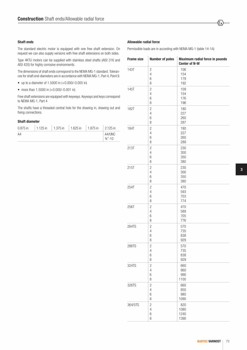
3
BARTEC VARNOST 73
Shaft ends
The standard electric motor is equipped with one free shaft extension. On request we can also supply versions with free shaft extensions on both sides.
Type 4KTU motors can be supplied with stainless steel shafts (AISI 316 and AISI 420) for highly corrosive environments.
The dimensions of shaft ends correspond to the NEMA MG-1 standard. Toleran-ces for shaft end-diameters are in accordance with NEMA MG-1, Part 4, Point 9.
• up to a diameter of 1.5000 in (+0.000/-0.005 in)
• more than 1.5000 in (+0.000/-0.001 in)
Free shaft extensions are equipped with keyways. Keyways and keys correspond to NEMA MG-1, Part 4
The shafts have a threaded central hole for the drawing in, drawing out and fixing connections.
Construction Shaft ends/Allowable radial force
0.875 in 1.125 in 1.375 in 1.625 in 1.875 in 2.125 in
A4 A4/UNC ¾"-10
Shaft diameter
Allowable radial force
Permissible loads are in according with NEMA MG-1 (table 14-1A)
Frame size Number of poles Maximum radial force in pounds Center of N-W
143T 2468
106154179192
145T 2468
109154176196
182T 2468
180227260287
184T 2468
180227260289
213T 2468
230300350380
215T 2468
230300350380
254T 2468
470593703774
256T 2468
470589705776
284TS 2468
570735838929
286TS 2468
570735838929
324TS 2468
660860990
1100
326TS 2468
660850980
1090
364/5TS 2468
820108012401390
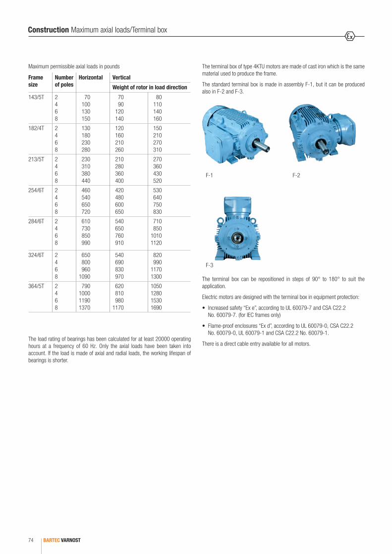
BARTEC VARNOST74
Construction Maximum axial loads/Terminal box
The terminal box of type 4KTU motors are made of cast iron which is the same material used to produce the frame.
The standard terminal box is made in assembly F-1, but it can be produced also in F-2 and F-3.
The terminal box can be repositioned in steps of 90° to 180° to suit the application.
Electric motors are designed with the terminal box in equipment protection:
• Increased safety “Ex e”, according to UL 60079-7 and CSA C22.2 No. 60079-7. (for IEC frames only)
• Flame-proof enclosures “Ex d”, according to UL 60079-0, CSA C22.2 No. 60079-0, UL 60079-1 and CSA C22.2 No. 60079-1.
There is a direct cable entry available for all motors.
F-1 F-2
F-3
Maximum permissible axial loads in pounds
Frame size
Number of poles
Horizontal Vertical
Weight of rotor in load direction
143/5T 2468
70100130150
7090
120140
80110140160
182/4T 2468
130180230280
120160210260
150210270310
213/5T 2468
230310380440
210280360400
270360430520
254/6T 2468
460540650720
420480600650
530640750830
284/6T 2468
610730850990
540650760910
710850
10101120
324/6T 2468
650800960
1090
540690830970
820990
11701300
364/5T 2468
790100011901370
620810980
1170
1050128015301690
The load rating of bearings has been calculated for at least 20000 operating hours at a frequency of 60 Hz. Only the axial loads have been taken into account. If the load is made of axial and radial loads, the working lifespan of bearings is shorter.

3
BARTEC VARNOST 75
Construction Terminal box
Terminal box entries
IEC frame NEMA frame Metric NPT
63 -2 x M25 + 1 x M20
3/4"
71 -
80 -
2 x M25 + 1 x M20
90 143/5
100 -
112 182/41"
132 213/5
160 254/6
2 x M50 + 2 x M20 2"180 284/6
200 324/6
225 364/5
Motors can also be connected with rigid metal conduit, of which the size and lengths are in accordance with this table:
Rigid conduit sizes and lengths
IEC frame NEMA frame Thread size Length
Metric NPT
63 -2 x M25 + 1 x M20
3/4"
2ft
71 -
80 -
3 x M32
90 143/5
100 -
112 182/41"
132 213/5
160 254/6
2 x M50 + 2 x M20 2" 18"180 284/6
200 324/6
225 364/5
The Ex d terminal box has a threaded entry to accept Ex d cable glands or rigid metal conduit. In a terminal box, there can be 6 or 12 main connection terminals and 6 additional terminals for PTC sensors, heaters, etc. Each terminal box has one earth connection terminal.
IEC: 71 IEC: 80-132/NEMA: 143/5 - 213/5
Ex d terminal box
IEC: 160-225/NEMA: 254/6 - 364/5
In the terminal box with increased safety and cable glands according to UL 60079-0, CSA C22.2 No. 60079-0, UL 60079-7 and CSA C22.2 No. 60079-7 are used. Cable glands are fitted for this purpose and are separately certified.
Frame size 71 Frame size 80 - 132
Ex e terminal box (IEC frames only)
Frame size 160 - 225
Ex d terminal box
Terminal boxes can have either metric or NPT threaded entries:
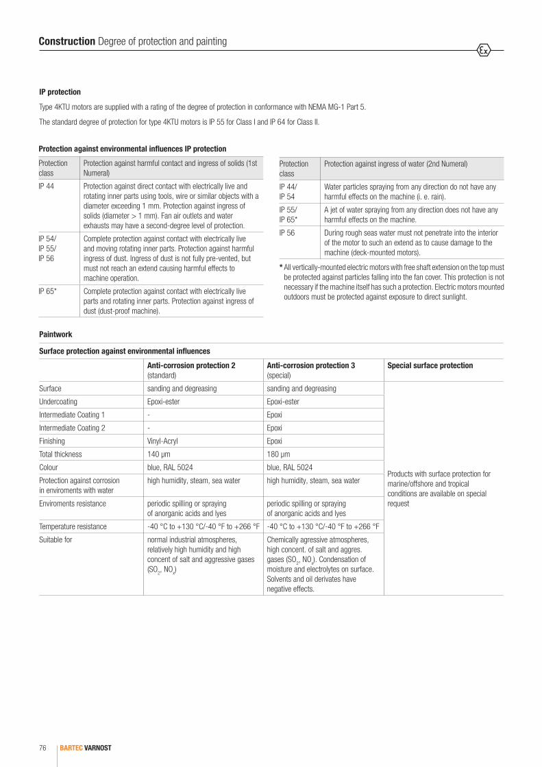
BARTEC VARNOST76
Construction Degree of protection and painting
IP protection
Type 4KTU motors are supplied with a rating of the degree of protection in conformance with NEMA MG-1 Part 5.
The standard degree of protection for type 4KTU motors is IP 55 for Class I and IP 64 for Class II.
* All vertically-mounted electric motors with free shaft extension on the top must be protected against particles falling into the fan cover. This protection is not necessary if the machine itself has such a protection. Electric motors mounted outdoors must be protected against exposure to direct sunlight.
Protection against environmental influences IP protection
Protection class
Protection against harmful contact and ingress of solids (1st Numeral)
IP 44 Protection against direct contact with electrically live and rotating inner parts using tools, wire or similar objects with a diameter exceeding 1 mm. Protection against ingress of solids (diameter > 1 mm). Fan air outlets and water exhausts may have a second-degree level of protection.
IP 54/ IP 55/ IP 56
Complete protection against contact with electrically live and moving rotating inner parts. Protection against harmful ingress of dust. Ingress of dust is not fully pre-vented, but must not reach an extend causing harmful effects to machine operation.
IP 65* Complete protection against contact with electrically live parts and rotating inner parts. Protection against ingress of dust (dust-proof machine).
Paintwork
Surface protection against environmental influences
Anti-corrosion protection 2 (standard)
Anti-corrosion protection 3 (special)
Special surface protection
Surface sanding and degreasing sanding and degreasing
Products with surface protection for marine/offshore and tropical conditions are available on special request
Undercoating Epoxi-ester Epoxi-ester
Intermediate Coating 1 - Epoxi
Intermediate Coating 2 - Epoxi
Finishing Vinyl-Acryl Epoxi
Total thickness 140 µm 180 µm
Colour blue, RAL 5024 blue, RAL 5024
Protection against corrosion in enviroments with water
high humidity, steam, sea water high humidity, steam, sea water
Enviroments resistance periodic spilling or spraying of anorganic acids and lyes
periodic spilling or spraying of anorganic acids and lyes
Temperature resistance -40 °C to +130 °C/-40 °F to +266 °F -40 °C to +130 °C/-40 °F to +266 °F
Suitable for normal industrial atmospheres, relatively high humidity and high concent of salt and aggressive gases (SO2, NOx)
Chemically agressive atmospheres, high concent. of salt and aggres. gases (SO2, NOx). Condensation of moisture and electrolytes on surface. Solvents and oil derivates have negative effects.
Protection class
Protection against ingress of water (2nd Numeral)
IP 44/ IP 54
Water particles spraying from any direction do not have any harmful effects on the machine (i. e. rain).
IP 55/ IP 65*
A jet of water spraying from any direction does not have any harmful effects on the machine.
IP 56 During rough seas water must not penetrate into the interior of the motor to such an extend as to cause damage to the machine (deck-mounted motors).
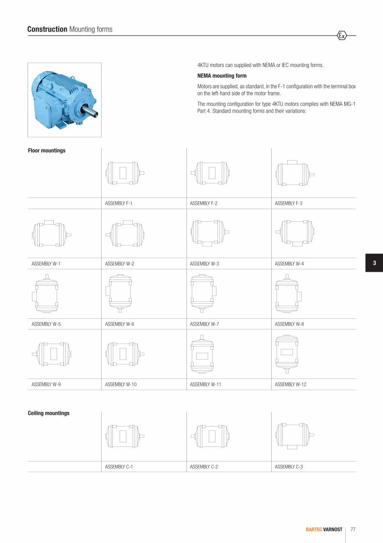
3
BARTEC VARNOST 77
Construction Mounting forms
4KTU motors can supplied with NEMA or IEC mounting forms.
NEMA mounting form
Motors are supplied, as standard, in the F-1 configuration with the terminal box on the left-hand side of the motor frame.
The mounting configuration for type 4KTU motors complies with NEMA MG-1 Part 4. Standard mounting forms and their variations:
ASSEMBLY F-1 ASSEMBLY F-2 ASSEMBLY F-3
ASSEMBLY W-1 ASSEMBLY W-2 ASSEMBLY W-3 ASSEMBLY W-4
ASSEMBLY W-5 ASSEMBLY W-6 ASSEMBLY W-7 ASSEMBLY W-8
ASSEMBLY W-9 ASSEMBLY W-10 ASSEMBLY W-11 ASSEMBLY W-12
ASSEMBLY C-1 ASSEMBLY C-2 ASSEMBLY C-3
Ceiling mountings
Floor mountings

BARTEC VARNOST78
IEC mounting form
Motors are supplied, as standard, with the terminal box on the left-hand side of the motor frame. The mounting form complies with IEC 60 034-7 Standard mounting forms and their variations:
IEC code I IM B3 IM B5 IM B34 IM B14 IM B35IEC code II IM 1001 IM 3001 IM 2101 IM 3601 IM 2001
IEC code I IM V6 IM V3 IM V6/IM V19 IM V19 IM V36IEC code II IM 1031 IM 3031 IM 3631 IM 2031
IEC code I IM V5 IM V1 IM V5/IM V18 IM V18 IM V15IEC code II IM 1011 IM 3011 IM 3611 IM 2011
Power voltage and service factor
The power ratings given in the tables are valid for operating under continuous load (S 1) at a rated voltage, a frequency of 60 Hz. temperature of up to +104 ˚F/+40 ˚C and an altitude of less than 1000 m above sea level. The data in the tables refer to 230/460 V.
NEMA MG-1 Part 12 states that the motor operates successfully under running conditions at a load with a variation in the voltage or frequency of up to the following:
• ±10 % of the rated voltage with rated frequency
• ±5 % of the rated frequency with rated voltage
• a combined variation in voltage and frequency of 10 % (sum of absolute values) of the rated values, provided the frequency variation does not exceed ±5 % of the rated frequency
The Motor Service Factor (SF) is the percentage of overloading that the motor can handle for short periods when operating normally within the correct voltage tolerances.
4KTU motors has a SF of 1.0 and 1.1.
Construction Mounting forms/Power voltage and service factor
T (˚F/˚C)Altitude (m)
1000 1500 2000 2500 3000 3500 4000 4500
10/50 0.97 0.92
15/59 0.96 0.94 0.90
20/68 1.00 0.95 0.91 0.87
25/77 1.00 0.95 0.93 0.80 0.85
30/86 1.00 0.96 0.92 0.90 0.86 0.82
35/95 1.00 0.95 0.93 0.90 0.88 0.84 0.80
40/104 1.00 0.97 0.94 0.90 0.86 0.82 0.80 0.76
45/113 0.95 0.92 0.90 0.88 0.85 0.81 0.76 0.74
50/122 0.92 0.92 0.87 0.85 0.82 0.80 0.77 0.72
55/131 0.88 0.85 0.83 0.81 0.78 0.76 0.73 0.70
60/140 0.83 0.82 0.80 0.77 0.75 0.73 0.70 0.67
Rated values under extreme working conditions
When electric motors are used at temperatures above +104 ˚F/+40 ˚C or at altitudes of more than 1000 m above sea level, the permitted overtemperature for windings is lower and the rated power is reduced respectively. The relation between rated power, ambient temperature, and altitude is shown in this table:

3
BARTEC VARNOST 79
Materials of thermal class F are used for the production of stator windings. They are designed to withstand an overtemperature of 80 K at maximum ambient tempe-rature of +104 ̊ F/+40 ̊ C. Electric motors operating under heavy conditions, conditions requiring frequent start-ups or ambient temperatures above +104 ̊ F/+40 ̊ C employ special insulation thermal class H and are available on special request.
Two speed motors with 2 : 1 speed ratio use Dahlander windings. Electric motors with pole relation of 4/8 or 8/6 have two separate stator windings in star connection.
3 phase - 9 lead - delta
Lines L1 L2 L3 Connected together Conn.
Low voltage T1 T6 T7 T2 T4 T8 T3 T5 T9
High voltage T1 T2 T3 T4 T7 - T5 T8 - T6 T9
Construction Windings
6 lead WYE delta star
Lines L1 L2 L3 Connected together Conn.
start T1 T2 T3 T4 T5 T6 Y
run T1 T6 T2 T4 T3 T5
Part winding start 3 Phase - 6 lead - WYE
Lines L1 L2 L3 Connected
start T1 T2 T3 T7 T8 T9 open
run T1 T7 T2 T8 T3 T9
Double winding
Lines L1 L2 L3 Connected Conn.
Low speed T1 T2 T3 T11 T12 T13 open Y
High speed T11 T12 T13 T1 T2 T3 open Y
Single winding
Lines L1 L2 L3 Connected Conn.
Low speed T1 T2 T3 T4 T5 T6 open Y
High speed T6 T4 T5 T1 T2 T3 together YY
Variable torque
Lines L1 L2 L3 Connected Conn.
Low speed T1 T2 T3 T4 T5 T6 open
High speed T6 T4 T5 T1 T2 T3 together YY
Constant torque
Lines L1 L2 L3 Connected Conn.
Low speed T1 T2 T3 T4 T5 T6 open YY
High speed T6 T4 T5 T1 T2 T3 together
Constant power
T1
T3 T2
T6
T9 T4T7
T8 T5
T6 T1
T3 T4
T5 T2
T7 T1
T3
T9
T8
T2
T1 T11
T3 T2 T13 T12
T4
T3
T1
T5T6T2
T4
T1T3
T5 T6
T2
T4
T3 T1
T5 T6
T2

BARTEC VARNOST80
Motor protectionContinuous duty motors must be protected from overload based on operating temperature or based on operating current. For overload protection based on operating temperature 4KTU motors can have built into the winding following sensors:
PTC thermistorWe use three PTC in serial connection, one per each phase. The nominal shutdown temperature is +248 °F/+120 °C.
PTO thermostatThere are three PTO, one per phase in serial connection with NC or NO contacts. The nominal shutdown temperature is +248 °F/+120 °C.There are also other types of thermal protection available: Pt100; KTY83/84
Space heatersSpace heaters must be applied when motors are intended to be used below -4 ˚F/-20 ˚C or for anti-condensation purposes.
Space heaters
Frame size (NEMA)
Frame size (IEC) Power Voltage
- 71 12.5 W
110 V or 230 V
- 80 25 W
143, 145 90 25 W
- 100 25 W
182, 184 112 50 W
213, 215 132 50 W
254, 256 160 75 W
284, 286 180 150 W
324, 326 200 200 W
364, 365 225 200 W
Construction Duty cycles
Duty cycles
S2 Short-time duty
Operation under constant load, for a time too short to allow the machine to reach thermal equilibrium. Idle time of the machine is long enough to allow the machine to cool down to ambient temperature.
Standard duration of short-term operation: 10, 30, 60 and 90 min.
Designation: S2 30 minutes.
S1 Continuous duty
Operation under constant load, last-ing long enough to allow the machine to reach thermal equilibrium.
Designation: S1
S3 Intermittent periodic duty
Operation under repeated, constant load in specified cycles. Neither operating nor resting period are long enough to allow the motor to reach thermal equilibrium. The starting losses are small and do not essentially influence the temperature rise. The nominal values of relative starting time are 15, 25, 40, 60 % at a daily 10-minute cycle.
Designation: S3 25 %
S4 Intermittent periodic duty
Operation under repeated, constant load in specified cycles. The start of the motor influences the temperature rise.
In order to define this type of ope-ration, the number of cycles (starts per hour) and inertia constant must also be known.
Designation: S4 40 %; 120 starts/h; FI2
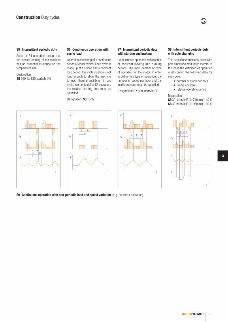
3
BARTEC VARNOST 81
Construction Duty cycles
S6 Continuous operation with cyclic load
Operation consisting of a continuous series of equal cycles. Each cycle is made up of a noload and a constant load period. The cycle duration is not long enough to allow the machine to reach thermal equilibrium in one cycle. In order to define S6 operation, the relative starting time must be specified.
Designation: S6 15 %
S5 Intermittent periodic duty
Same as S4 operation, except that the electric braking of the machine has an essential influence on the temperature rise.
Designation: S5 160 %; 120 starts/h; FI2
S7 Intermittent periodic duty with starting and braking
Uninterrupted operation with a series of constant loading and braking periods. The most demanding type of operation for the motor. In order to define this type of operation, the number of cycles per hour and the inertia constant must be specified.
Designation: S7 500 starts/h; FI3
S8 Intermittent periodic duty with pole changing
This type of operation only exists with pole amplitude modulated motors. In this case the definition of operation must contain the following data for each pole: •number of starts per hour •inertia constant •relative operating period
Designation: S8 30 starts/h; FI10; 740 min-1; 40 %S8 30 starts/h; FI10; 960 min-1; 60 %
S9 Continuous operation with non-periodic load and speed variation (e. g. converter operation)

BARTEC VARNOST82
Construction 4KTU motors
Type 4KTU motors can be equipped with brakes, which are separately certified for suitable explosion protection. The brake can be mounted on the drive end or non-drive end of the motor. The electrical connection of brakes is made in a separate terminal box on the brake.
The electrical, as well as mechanical, characteristics of the brakes is not part of this catalogue and can be found in the brake catalogue.
The dimension of the motors with direct cable entries please see the relevant table at the end of the brochure.
Motors with brakes
Type 4KTU can be run with a frequency inverter. When you want to run the motor below 30 Hz, cooling is not enough. In those cases, a forced ventilation kit can be supplied for type 4KTU motors, which consist of one additional independent motor that drives the fan of the main motor.
The dimension of the motors with direct cable entries please see the relevant table at the end of the brochure.
Forced cooling
Type 4KTU motors can be supplied with encoders for speed control or for positioning. Encoders can be fitted onto motors with either forced ventilation or with shaft mounted cooling fans (TEFC).
Encoders are separately certified for suitable explosion protection. We usually use encoders from the brands Kuebler or Liende&Liende. Other encoder brands can also be used.
The dimensions of motors with encoders please see the relevant table at the end of the brochure.
Motors with encoders
Motors type 4KTU can be produced without a terminal box. This application is very suitable for machines with limited space for example those using axial fans. For this application we use special flameproof cable entries. The type of cables, cross section and length can be adapted as per request.
There is a place for grounding the cable entry from inside the terminal plate.
The dimension of the motors with direct cable entries please see the relevant table at the end of the brochure.
Direct cable entries

3
BARTEC VARNOST 83
Construction Variable speed
Electrical data for variable speed motors
General descriptionThe asynchronous motor with its short-circuit and robust construction offers an excellent price-performance ratio. AC motors are designed for constant speed operation. It is not possible to change speed when they are running on fixed frequency supplies. There are drives which require the additional flexibility of smooth speed variations and this is best achieved with the use of an inverter.
Frequency inverters provide an excellent speed and the speed can be varied continuously over the entire frequency range. To avoid overheating, three PTC elements are built into the head of the winding. As the speed rises (higher frequency), the motor becomes louder. Voltage type frequency inverters cause a noise increase of about 7 to 15 dB, current ones of about 3 dB.
We strongly recommend that you indicate frequency range and working charac-teristics of the motor (T = f (n) or P = f (n)) when placing your order.
Where
Ur : rated stator voltagefr : rated stator frequencyU : stator voltagef : stator frequency
Where
Tr : rated torqueT : torque available on the shaft
Power and torque characteristics of motors driven by frequency inverters
Range above the rated frequen-cy is known as field weakening, where flux decreases as a result of frequency increase, causing the motor torque to decrease gradually.
Where
Pr : rated power P : power available on the shaft
The output is proportional to torque time speed, it grows linearly up to the rated frequency and from that point upwards it is kept constant.
Ur
fr
Volta
ge
Frequency0
U, f
Pr
fr
Powe
r
Frequency0
P
Tr
fr
Torq
ue
Frequency0
T
Variable speed drive application
Type 4KTU motors are designed and certified for variable speed applications in the following ranges:
Frequency range: from 5 Hz to 87 Hz
Speed range: 75 min-1 to 5220 min-1
There are also pole-switching motors available with standard ratios of 4/2, 8/4, 6/4, 8/6. Other ratios are possible upon request.
To avoid overheating, three PTC thermistors are built into the head of the win-ding. When you want to run the motor below 30 Hz, cooling is not enough, and forced cooling must be used.
Power and torque characteristics of motors driven by frequency inverters We distinguish two ranges:
5 Hz to 60 HzHere, the motor develops normal torque on the shaft at 5 Hz to 10 Hz of its output frequency (10 to 20 % of nominal speed). The motor maintains normal torque at the shaft until the frequency reaches 60 Hz (100 % of the nominal speed). Voltage keeps rising while the magnetic flux is kept constant. The power increase in this range is linear to the revolution (P = k x M x n)
60 Hz to 87 HzHere the torque is parallel to the speed. The voltage of the motor is maintained on a constant level while the magnetic flux is weaker. The current level is maintained and independent of the speed.
1
0 5 10 20 30 40 50 60 70 80 87
MN = const UN = const
UFR
UN
MN
MFR
UN : net voltageUFR : voltage of frequency inverterMN : motor torque on netMFR : motor torque on frequency inverter
The ratio U/f is constant in range from 0 Hz to motor rated frequency. From rated frequency upwards the voltage is kept constant at its rated value, while the motor (on the stator windings) frequency keeps growing.
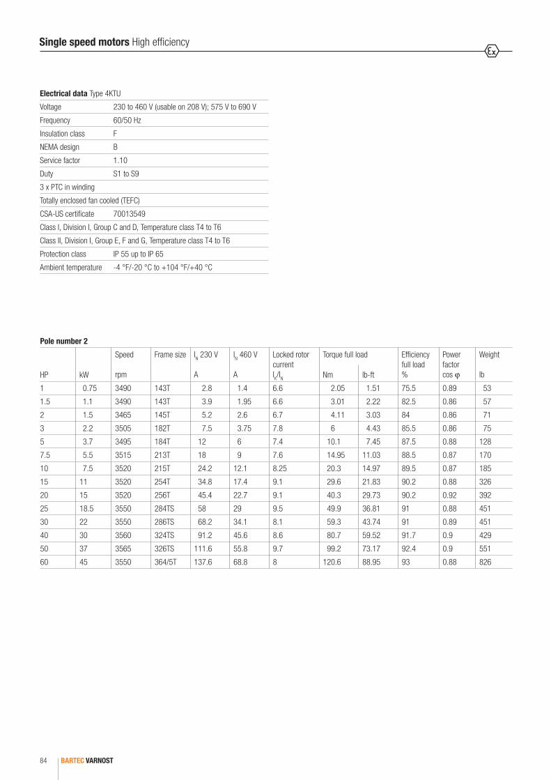
BARTEC VARNOST84
Pole number 2
HP kW
Speed
rpm
Frame size IN 230 V
A
IN 460 V
A
Locked rotor currentIK/IN
Torque full load Efficiency full load %
Power factor cos ϕ
Weight
lbNm lb-ft
1 0.75 3490 143T 2.8 1.4 6.6 2.05 1.51 75.5 0.89 53
1.5 1.1 3490 143T 3.9 1.95 6.6 3.01 2.22 82.5 0.86 57
2 1.5 3465 145T 5.2 2.6 6.7 4.11 3.03 84 0.86 71
3 2.2 3505 182T 7.5 3.75 7.8 6 4.43 85.5 0.86 75
5 3.7 3495 184T 12 6 7.4 10.1 7.45 87.5 0.88 128
7.5 5.5 3515 213T 18 9 7.6 14.95 11.03 88.5 0.87 170
10 7.5 3520 215T 24.2 12.1 8.25 20.3 14.97 89.5 0.87 185
15 11 3520 254T 34.8 17.4 9.1 29.6 21.83 90.2 0.88 326
20 15 3520 256T 45.4 22.7 9.1 40.3 29.73 90.2 0.92 392
25 18.5 3550 284TS 58 29 9.5 49.9 36.81 91 0.88 451
30 22 3550 286TS 68.2 34.1 8.1 59.3 43.74 91 0.89 451
40 30 3560 324TS 91.2 45.6 8.6 80.7 59.52 91.7 0.9 429
50 37 3565 326TS 111.6 55.8 9.7 99.2 73.17 92.4 0.9 551
60 45 3550 364/5T 137.6 68.8 8 120.6 88.95 93 0.88 826
Single speed motors High efficiency
Electrical data Type 4KTU
Voltage 230 to 460 V (usable on 208 V); 575 V to 690 V
Frequency 60/50 Hz
Insulation class F
NEMA design B
Service factor 1.10
Duty S1 to S9
3 x PTC in winding
Totally enclosed fan cooled (TEFC)
CSA-US certificate 70013549
Class I, Division I, Group C and D, Temperature class T4 to T6
Class II, Division I, Group E, F and G, Temperature class T4 to T6
Protection class IP 55 up to IP 65
Ambient temperature -4 °F/-20 °C to +104 °F/+40 °C

3
BARTEC VARNOST 85
Pole number 4
HP kW
Speed
rpm
Frame size IN 230 V
A
IN 460 V
A
Locked rotor currentIK/IN
Torque full load Efficiency full load %
Power factor cos ϕ
Weight
lbNm lb-ft
1 0.75 1745 143T 3.3 1.65 6.9 4.11 3.03 82.5 0.69 75
1.5 1.1 1750 143T 4.8 2.4 7.7 6.01 4.43 84 0.68 77
2 1.5 1735 145T 5.8 2.9 6.5 8.25 6.09 84 0.77 77
3 2.2 1740 182T 7.6 3.8 7.1 12 8.85 87.5 0.83 132
5 3.7 1750 184T 13.2 6.6 7.7 20.2 14.90 87.5 0.8 132
7.5 5.5 1745 213T 18.6 9.3 6.1 30.1 22.20 89.5 0.83 185
10 7.5 1750 215T 25 12.5 6.9 40.9 30.2 89.5 0.84 206
15 11 1760 254T 36.8 18.4 7.6 59.7 44.03 91 0.82 350
20 15 1755 256T 49.4 24.7 7.6 81.6 60.19 91 0.84 392
25 18.5 1770 284TS 59.8 29.9 7.2 99.7 73.54 92.4 0.84 474
30 22 1770 286TS 71 35.5 7.6 118.5 87.41 92.4 0.84 520
40 30 1770 324TS 92 46 8.3 161.7 119.27 93 0.88 551
50 37 1775 326TS 112.2 56.1 6.8 200.3 147.74 93 0.89 551
60 45 1775 364/5T 139.6 69.8 7.6 238.24 175.7 93.6 0.86 859
Pole number 6
HP kW
Speed
rpm
Frame size IN 230 V
A
IN 460 V
A
Locked rotor currentIK/IN
Torque full load Efficiency full load %
Power factor cos ϕ
Weight
lbNm lb-ft
1 0.75 1165 143/5T 4.3 2.15 6.3 6.14 4.53 80 0.55 70.5
1.5 1.1 1170 182/4T 4.4 2.2 7 9.1 6.71 85.5 0.73 132
2 1.5 1175 182/4T 6.8 3.4 8.2 12.2 9.00 86.5 0.64 132
3 2.2 1170 213/5T 9.4 4.7 7.8 17.9 13.20 87.5 0.67 185
5 3.7 1165 213/5T 14 7 6.2 30.3 22.35 87.5 0.76 194
7.5 5.5 1170 254/6T 19.5 9.75 8 44.8 33.04 89.5 0.79 354
10 7.5 1175 254/6T 27 13.5 8.7 60.8 44.85 89.5 0.78 401
15 11 1180 284/6T 39 19.5 8.5 88.9 65.57 90.2 0.78 520
20 15 1175 284/6T 50.2 25.1 6.6 122 89.99 91. 0.82 520
25 18.5 1185 324/6T 67.4 33.7 7.4 148.8 109.75 91.7 0.75 529
30 22 1185 324/6T 77.2 38.6 8.5 177.9 131.22 91.7 0.78 551
40 30 1185 364/5T 100 50 7.6 214.5 158.22 93 0.81 859
50 37 1185 364/5T 120.2 60.1 6.3 298.8 220.39 93 0.83 859
Single speed motors High efficiency
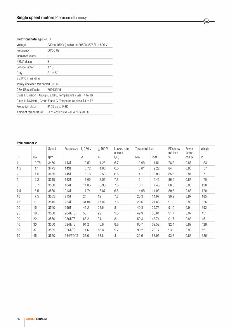
BARTEC VARNOST86
Pole number 2
HP kW
Speed
rpm
Frame size IN 230 V
A
IN 460 V
A
Locked rotor currentIK/IN
Torque full load Efficiency full load %
Power factor cos ϕ
Weight
lbNm lb-ft
1 0.75 3480 143T 2.52 1.26 6.7 2.05 1.51 78.5 0.87 53
1.5 1.1 3475 143T 3.72 1.86 6.5 3.01 2.22 84 0.86 57
2 1.5 3465 145T 5.18 2.59 6.6 4.11 3.03 85.5 0.84 71
3 2.2 3315 182T 7.06 3.53 7.8 6 4.43 86.5 0.88 75
5 3.7 3500 184T 11.86 5.93 7.5 10.1 7.45 88.5 0.88 128
7.5 5.5 3530 213T 17.74 8.87 6.8 14.95 11.03 89.5 0.86 170
10 7.5 3535 215T 24 12 7.2 20.3 14.97 90.2 0.87 185
15 11 3545 254T 34.04 17.02 7.6 29.6 21.83 91.0 0.89 326
20 15 3540 256T 45.2 22.6 8 40.3 29.73 91.0 0.9 392
25 18.5 3550 284T/TS 58 29 9.5 49.9 36.81 91.7 0.87 451
30 22 3550 286T/TS 68.2 34.1 8.1 59.3 43.74 91.7 0.88 451
40 30 3560 324T/TS 91.2 45.6 8.6 80.7 59.52 92.4 0.89 429
50 37 3565 326T/TS 111.6 55.8 9.7 99.2 73.17 93 0.89 551
60 45 3550 364/5T/TS 137.6 68.8 8 120.6 88.95 93.6 0.88 826
Single speed motors Premium efficiency
Electrical data Type 4KTU
Voltage 230 to 460 V (usable on 208 V); 575 V to 690 V
Frequency 60/50 Hz
Insulation class F
NEMA design B
Service factor 1.10
Duty S1 to S9
3 x PTC in winding
Totally enclosed fan cooled (TEFC)
CSA-US certificate 70013549
Class I, Division I, Group C and D, Temperature class T4 to T6
Class II, Division I, Group F and G, Temperature class T4 to T6
Protection class IP 55 up to IP 65
Ambient temperature -4 °F/-20 °C to +104 °F/+40 °C
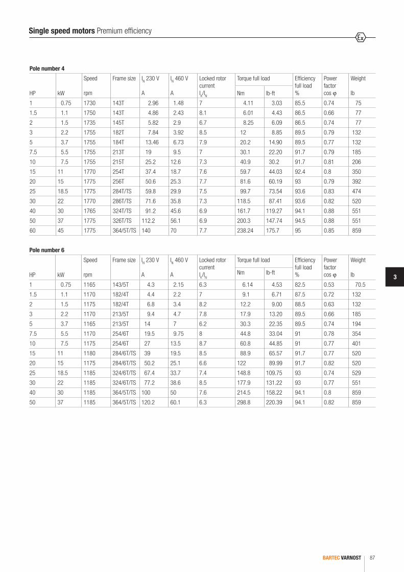
3
BARTEC VARNOST 87
Pole number 4
HP kW
Speed
rpm
Frame size IN 230 V
A
IN 460 V
A
Locked rotor currentIK/IN
Torque full load Efficiency full load %
Power factor cos ϕ
Weight
lbNm lb-ft
1 0.75 1730 143T 2.96 1.48 7 4.11 3.03 85.5 0.74 75
1.5 1.1 1750 143T 4.86 2.43 8.1 6.01 4.43 86.5 0.66 77
2 1.5 1735 145T 5.82 2.9 6.7 8.25 6.09 86.5 0.74 77
3 2.2 1755 182T 7.84 3.92 8.5 12 8.85 89.5 0.79 132
5 3.7 1755 184T 13.46 6.73 7.9 20.2 14.90 89.5 0.77 132
7.5 5.5 1755 213T 19 9.5 7 30.1 22.20 91.7 0.79 185
10 7.5 1755 215T 25.2 12.6 7.3 40.9 30.2 91.7 0.81 206
15 11 1770 254T 37.4 18.7 7.6 59.7 44.03 92.4 0.8 350
20 15 1775 256T 50.6 25.3 7.7 81.6 60.19 93 0.79 392
25 18.5 1775 284T/TS 59.8 29.9 7.5 99.7 73.54 93.6 0.83 474
30 22 1770 286T/TS 71.6 35.8 7.3 118.5 87.41 93.6 0.82 520
40 30 1765 324T/TS 91.2 45.6 6.9 161.7 119.27 94.1 0.88 551
50 37 1775 326T/TS 112.2 56.1 6.9 200.3 147.74 94.5 0.88 551
60 45 1775 364/5T/TS 140 70 7.7 238.24 175.7 95 0.85 859
Pole number 6
HP kW
Speed
rpm
Frame size IN 230 V
A
IN 460 V
A
Locked rotor currentIK/IN
Torque full load Efficiency full load %
Power factor cos ϕ
Weight
lbNm lb-ft
1 0.75 1165 143/5T 4.3 2.15 6.3 6.14 4.53 82.5 0.53 70.5
1.5 1.1 1170 182/4T 4.4 2.2 7 9.1 6.71 87.5 0.72 132
2 1.5 1175 182/4T 6.8 3.4 8.2 12.2 9.00 88.5 0.63 132
3 2.2 1170 213/5T 9.4 4.7 7.8 17.9 13.20 89.5 0.66 185
5 3.7 1165 213/5T 14 7 6.2 30.3 22.35 89.5 0.74 194
7.5 5.5 1170 254/6T 19.5 9.75 8 44.8 33.04 91 0.78 354
10 7.5 1175 254/6T 27 13.5 8.7 60.8 44.85 91 0.77 401
15 11 1180 284/6T/TS 39 19.5 8.5 88.9 65.57 91.7 0.77 520
20 15 1175 284/6T/TS 50.2 25.1 6.6 122 89.99 91.7 0.82 520
25 18.5 1185 324/6T/TS 67.4 33.7 7.4 148.8 109.75 93 0.74 529
30 22 1185 324/6T/TS 77.2 38.6 8.5 177.9 131.22 93 0.77 551
40 30 1185 364/5T/TS 100 50 7.6 214.5 158.22 94.1 0.8 859
50 37 1185 364/5T/TS 120.2 60.1 6.3 298.8 220.39 94.1 0.82 859
Single speed motors Premium efficiency
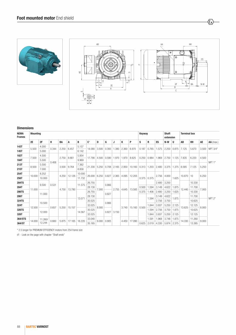
BARTEC VARNOST88
DimensionsNEMA Frames
Mounting Keyway Shaft extension
Terminal box
2E 2F H BA A B C* D G J K P S R ES N-W U AB HH AE AA (max.)
143T5.500
4.0000.344 2.250 6.457
5.15714.580 3.500 0.393 1.380 2.360 6.970 0.187 0.765 1.575 2.250 0.875 7.125 5.670 3.500 NPT 3/4"
145T 5.000 6.142
182T7.500
4.500
0.406
2.750 8.6615.954
17.790 4.500 0.590 1.970 1.970 8.625 0.250 0.984 1.969 2.750 1.125 7.835 6.220 4.500
NPT 1"184T 5.500 9.969
213T8.500
5.5003.500 9.764
7.36221.330 5.250 0.708 2.165 2.950 10.160 0.313 1.203 2.480 3.375 1.375 8.585 7.125 5.250
215T 7.000 8.858
254T10.000
8.252
0.531
4.250 12.12610.000
26.000 6.250 0.827 2.365 4.095 12.2050.375 0.375
2.756 4.0001.625
10.870 10 6.250
NPT 2"
256T 10.000 11.732
284TS
11.000
9.500
4.750 13.780
11.57526.755
7.000
0.866
2.755 4.645 13.585
2.480 3.250
12.440
10.330
7.000284T 28.130 0.500 1.594 3.149 4.622 1.875 11.700
286TS11.000
13.071
26.7550.827
0.375 1.406 2.480 3.250 1.625 10.330
286T 28.130
0.500
1.5943.149 4.622
1.87511.700
324TS
12.500
10.500
0.657 5.250 15.157
30.525
8.000
0.866
3.150
3.740 15.160
2.756 3.750
13.625
10.625
8.000324T 32.025 1.844 3.937 5.250 2.125 12.125
326TS12.000 14.567
30.5250.827
1.594 2.756 3.750 1.875 10.625
326T 32.025 1.844 3.937 5.250 2.125 12.125
364/5TS14.000
11.260/ 12.244
0.660 5.875 17.165 16.22033.040
9.000 0.905 4.450 17.0901.591 1.968 3.748 1.875
14.33011.260
9.000364/5T 35.165 0.625 2.019 4.330 5.874 2.375 13.385
AB
AE DG
O
A
HJ
2E 2FBC
P
AA HH
ES
BA N-WK
S
d1
R
U
* 2.5 longer for PREMIUM EFFICIENCY motors from 254 frame size
d1 - Look on the page with chapter “Shaft ends”
Foot mounted motor End shield

3
BARTEC VARNOST 89
Dimensions
NEMA Frames
Mounting Keyway Shaft extension Terminal box
2E 2F H A B C*** D G J K P S R ES N-W U AB HH AE AA (max.)
143T5.500
4.0000.344 6.457
5.15714.580 3.500 0.393 1.380 2.360 6.970 0.187 0.765 1.575 2.250 0.875 7.125 5.670 3.500 NPT 3/4"
145T 5.000 6.142
182T7.500
4.500
0.406
8.6615.954
17.790 4.500 0.590 1.970 1.970 8.625 0.250 0.984 1.969 2.750 1.125 7.835 6.220 4.500
NPT 1"184T 5.500 9.969
213T8.500
5.5009.764
7.36221.330 5.250 0.708 2.165 2.950 10.160 0.313 1.203 2.480 3.375 1.375 8.585 7.125 5.250
215T 7.000 8.858
254T10.000
8.252
0.531
12.12610.000
26.000 6.250 0.827 2.365 4.095 12.2050.375 0.375
2.756 4.0001.625
10.870 10 6.250
NPT 2"
256T 10.000 11.732
284TS
11.000
9.500
13.780
11.57526.755
7.000
0.866
2.755 4.645 13.585
2.480 3.250
12.440
10.330
7.000284T 28.130 0.500 1.594 3.149 4.622 1.875 11.700
286TS11.000
13.071
26.7550.827
0.375 1.406 2.480 3.250 1.625 10.330
286T 28.130
0.500
1.5943.149 4.622
1.87511.700
324TS
12.500
10.500
0.657 15.157
30.525
8.000
0.866
3.150
3.740 15.160
2.756 3.750
13.625
10.625
8.000324T 32.025 1.844 3.937 5.250 2.125 12.125
326TS12.000 14.567
30.5250.827
1.594 2.756 3.750 1.875 10.625
326T 32.025 1.844 3.937 5.250 2.125 12.125
364/5TS14.000
11.260/ 12.244
0.660 17.165 16.22033.040
9.000 0.905 4.450 17.0901.591 1.968 3.748 1.875
14.33011.260
9.000364/5T 35.165 0.625 2.019 4.330 5.874 2.375 13.385
NEMA Frames
“C” Flange
BA AJ AK BD No. BF BB BC AH
143T 2.250*5.875 4.500 6.500
4
UNC 3/8" x 16
0.156
0.125
2.125145T 2.750**
182T 2.750*
7.250 8.500 8.875
UNC 1/2" x 13
0.250
2.625184T 3.500**
213T 3500*
0.250
3.125215T 4.250**
254T 4.250*3.750
256T 4750**
284TS
4.750 9.000 10.500 11.031
3.000
284T 4.375
286TS 3.000
286T 4.375
324TS
5.250
11.000 12.500
13.583UNC 5/8" x 11
3.500
324T 5.000
326TS 3.500
326T 5.000
364/5TS5.875 15.551 8
3.500
364/5T 5.625
* NEMA Standard ** BA Dimension for motors with “C” Flange *** 2.5 longer for PREMIUM EFFICIENCY motors from 254 frame size
d1 - Look on the page with chapter “Shaft ends”
Foot mounted motor C Face

BARTEC VARNOST90
NEMA Frames
“D” Flange
BA AJ AK BD No. BF BB
143T2.250
10.000 9.000 11.000
4
0.562
0.203
145T
182T2.750
0.828
184T
213T3.500
215T
254T4.250
12.500 11.000 14.000
256T
284TS
4.750284T
286TS
286T
324TS
5.250
16.000 14.000
18.000324T
326TS
326T
364/5TS5.875 17.716
364/5T
Dimensions
NEMA Frames
Mounting Keyway Shaft extension Terminal box
2E 2F H A B C* D G J K P S R ES N-W U AB HH AE AA (max.)
143T5.500
4.0000.344 6.457
5.15714.580 3.500 0.393 1.380 2.360 6.970 0.187 0.765 1.575 2.250 0.875 7.125 5.670 3.500 NPT 3/4"
145T 5.000 6.142
182T7.500
4.500
0.406
8.6615.954
17.790 4.500 0.590 1.970 1.970 8.625 0.250 0.984 1.969 2.750 1.125 7.835 6.220 4.500
NPT 1"184T 5.500 9.969
213T8.500
5.5009.764
7.36221.330 5.250 0.708 2.165 2.950 10.160 0.313 1.203 2.480 3.375 1.375 8.585 7.125 5.250
215T 7.000 8.858
254T10.000
8.252
0.531
12.12610.000
26.000 6.250 0.827 2.365 4.095 12.2050.375 0.375
2.756 4.0001.625
10.870 10 6.250
NPT 2"
256T 10.000 11.732
284TS
11.000
9.500
13.780
11.57526.755
7.000
0.866
2.755 4.645 13.585
2.480 3.250
12.440
10.330
7.000284T 28.130 0.500 1.594 3.149 4.622 1.875 11.700
286TS11.000
13.071
26.7550.827
0.375 1.406 2.480 3.250 1.625 10.330
286T 28.130
0.500
1.5943.149 4.622
1.87511.700
324TS
12.500
10.500
0.657 15.157
30.525
8.000
0.866
3.150
3.740 15.160
2.756 3.750
13.625
10.625
8.000324T 32.025 1.844 3.937 5.250 2.125 12.125
326TS12.000 14.567
30.5250.827
1.594 2.756 3.750 1.875 10.625
326T 32.025 1.844 3.937 5.250 2.125 12.125
364/5TS14.000
11.260/ 12.244
0.660 17.165 16.22033.040
9.000 0.905 4.450 17.0901.591 1.968 3.748 1.875
14.33011.260
9.000364/5T 35.165 0.625 2.019 4.330 5.874 2.375 13.385
* 2.5 longer for PREMIUM EFFICIENCY motors from 254 frame sized1 - Look on the page with chapter “Shaft ends”
Foot mounted motor D Flange

3
BARTEC VARNOST 91
NEMA Frames
“C” Flange
AJ AK BD No. BF BB BC AH
143T5.875 4.500 6.500
4
UNC 3/8" x 16
0.156
0.125
2.125145T
182T
7.250 8.500 8.875
UNC 1/2" x 13
0.250
2.625184T
213T
0.250
3.125215T
254T3.750
256T
284TS
9.000 10.500 11.031
3.000
284T 4.375
286TS 3.000
286T 4.375
324TS
11.000 12.500
13.583UNC 5/8" x 11
3.500
324T 5.000
326TS 3.500
326T 5.000
364/5TS15.551 8
3.500
364/5T 5.625
Dimensions
NEMA Frames
Keyway Shaft extension Terminal box
C* P S R ES N-W U AB HH AA (max.)
143T14.580 6.970 0.187 0.765 1.575 2.250 0.875 7.125 5.670 NPT 3/4"
145T
182T17.790 8.625 0.250 0.984 1.969 2.750 1.125 7.835 6.220
NPT 1"184T
213T21.330 10.160 0.313 1.203 2.480 3.375 1.375 8.585 7.125
215T
254T26.000 12.205
0.375 0.3752.756 4.000
1.62510.870 10
NPT 2"
256T
284TS 26.755
13.585
2.480 3.250
12.440
10.330
284T 28.130 0.500 1.594 3.149 4.622 1.875 11.700
286TS 26.755 0.375 1.406 2.480 3.250 1.625 10.330
286T 28.130
0.500
1.5943.149 4.622
1.87511.700
324TS 30.525
15.160
2.756 3.750
13.625
10.625
324T 32.025 1.844 3.937 5.250 2.125 12.125
326TS 30.525 1.594 2.756 3.750 1.875 10.625
326T 32.025 1.844 3.937 5.250 2.125 12.125
364/5TS 33.04017.090
1.591 1.968 3.748 1.87514.330
11.260
364/5T 35.165 0.625 2.019 4.330 5.874 2.375 13.385
* 2.5 longer for PREMIUM EFFICIENCY motors from 254 frame sized1 - Look on the page with chapter “Shaft ends”
Round body motor C Face

BARTEC VARNOST92
NEMA Frames
“D” Flange
AJ AK BD No. BF BB
143T
10.000 9.000 11.000
4
0.562
0.203
145T
182T
0.828
184T
213T
215T
254T
12.500 11.000 14.000
256T
284TS
284T
286TS
286T
324TS
16.000 14.000
18.000324T
326TS
326T
364/5TS17.716
364/5T
Dimensions
NEMA Frames
Keyway Shaft extension Terminal box
C* P S R ES N-W U AB HH AA (max.)
143T14.580 6.970 0.187 0.765 1.575 2.250 0.875 7.125 5.670 NPT 3/4"
145T
182T17.790 8.625 0.250 0.984 1.969 2.750 1.125 7.835 6.220
NPT 1"184T
213T21.330 10.160 0.313 1.203 2.480 3.375 1.375 8.585 7.125
215T
254T26.000 12.205
0.375 0.3752.756 4.000
1.62510.870 10
NPT 2"
256T
284TS 26.755
13.585
2.480 3.250
12.440
10.330
284T 28.130 0.500 1.594 3.149 4.622 1.875 11.700
286TS 26.755 0.375 1.406 2.480 3.250 1.625 10.330
286T 28.130
0.500
1.5943.149 4.622
1.87511.700
324TS 30.525
15.160
2.756 3.750
13.625
10.625
324T 32.025 1.844 3.937 5.250 2.125 12.125
326TS 30.525 1.594 2.756 3.750 1.875 10.625
326T 32.025 1.844 3.937 5.250 2.125 12.125
364/5TS 33.04017.090
1.591 1.968 3.748 1.87514.330
11.260
364/5T 35.165 0.625 2.019 4.330 5.874 2.375 13.385
HHAB90°
45°
AJ
BF
ES
BB
P AK BD
N-WCS
d1
R
U
* 2.5 longer for PREMIUM EFFICIENCY motors from 254 frame size
d1 - Look on the page with chapter “Shaft ends”
Round body motor D Flange
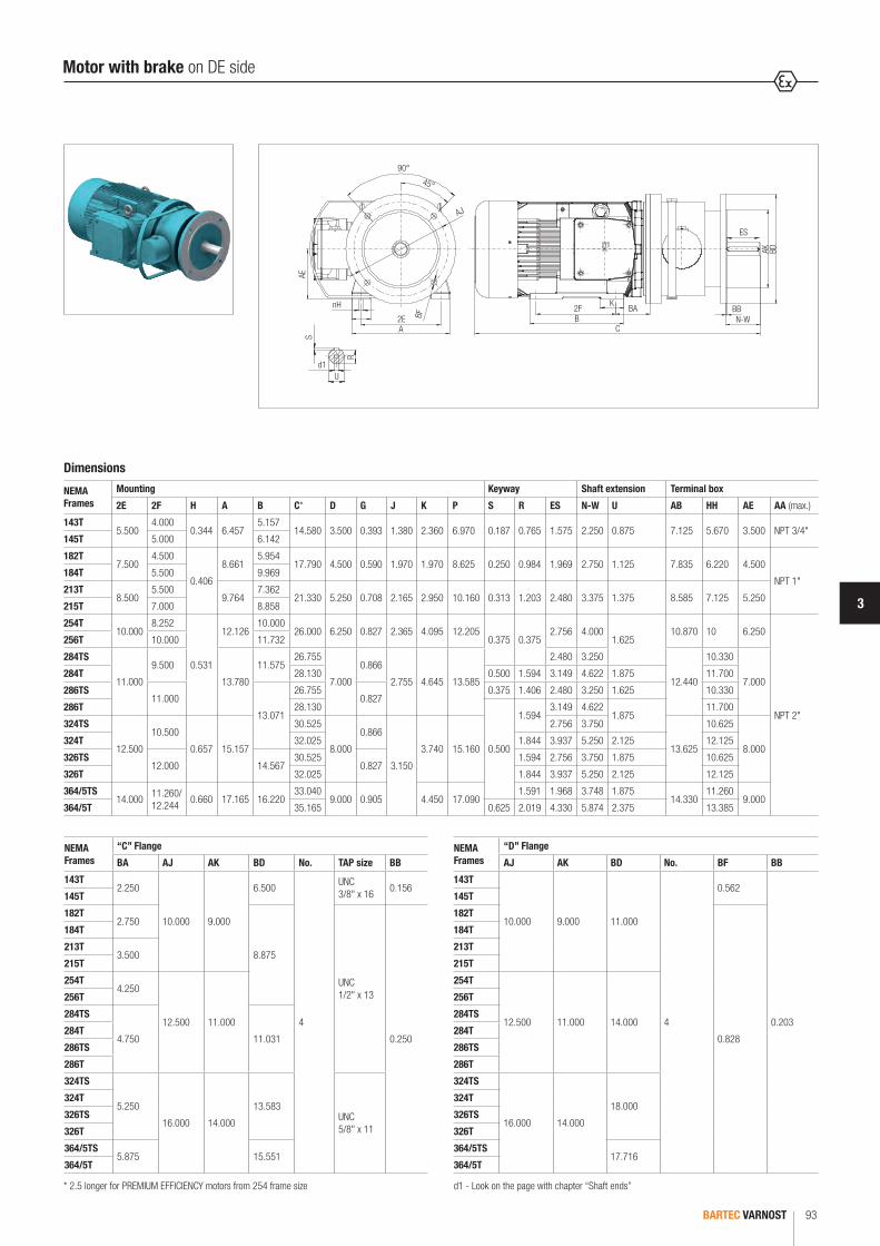
3
BARTEC VARNOST 93
NEMA Frames
“C” Flange
BA AJ AK BD No. TAP size BB
143T2.250
10.000 9.000
6.500
4
UNC 3/8" x 16
0.156145T
182T2.750
8.875
UNC 1/2" x 13
0.250
184T
213T3.500
215T
254T4.250
12.500 11.000
256T
284TS
4.750 11.031284T
286TS
286T
324TS
5.250
16.000 14.000
13.583UNC 5/8" x 11
324T
326TS
326T
364/5TS5.875 15.551
364/5T
Dimensions
NEMA Frames
Mounting Keyway Shaft extension Terminal box
2E 2F H A B C* D G J K P S R ES N-W U AB HH AE AA (max.)
143T5.500
4.0000.344 6.457
5.15714.580 3.500 0.393 1.380 2.360 6.970 0.187 0.765 1.575 2.250 0.875 7.125 5.670 3.500 NPT 3/4"
145T 5.000 6.142
182T7.500
4.500
0.406
8.6615.954
17.790 4.500 0.590 1.970 1.970 8.625 0.250 0.984 1.969 2.750 1.125 7.835 6.220 4.500
NPT 1"184T 5.500 9.969
213T8.500
5.5009.764
7.36221.330 5.250 0.708 2.165 2.950 10.160 0.313 1.203 2.480 3.375 1.375 8.585 7.125 5.250
215T 7.000 8.858
254T10.000
8.252
0.531
12.12610.000
26.000 6.250 0.827 2.365 4.095 12.2050.375 0.375
2.756 4.0001.625
10.870 10 6.250
NPT 2"
256T 10.000 11.732
284TS
11.000
9.500
13.780
11.57526.755
7.000
0.866
2.755 4.645 13.585
2.480 3.250
12.440
10.330
7.000284T 28.130 0.500 1.594 3.149 4.622 1.875 11.700
286TS11.000
13.071
26.7550.827
0.375 1.406 2.480 3.250 1.625 10.330
286T 28.130
0.500
1.5943.149 4.622
1.87511.700
324TS
12.500
10.500
0.657 15.157
30.525
8.000
0.866
3.150
3.740 15.160
2.756 3.750
13.625
10.625
8.000324T 32.025 1.844 3.937 5.250 2.125 12.125
326TS12.000 14.567
30.5250.827
1.594 2.756 3.750 1.875 10.625
326T 32.025 1.844 3.937 5.250 2.125 12.125
364/5TS14.000
11.260/ 12.244
0.660 17.165 16.22033.040
9.000 0.905 4.450 17.0901.591 1.968 3.748 1.875
14.33011.260
9.000364/5T 35.165 0.625 2.019 4.330 5.874 2.375 13.385
A
90°
45°
AJ
BF
ES
BB
C
AK BD
N-W2E
nHAE
BAB2F
KS
d1
R
U
NEMA Frames
“D” Flange
AJ AK BD No. BF BB
143T
10.000 9.000 11.000
4
0.562
0.203
145T
182T
0.828
184T
213T
215T
254T
12.500 11.000 14.000
256T
284TS
284T
286TS
286T
324TS
16.000 14.000
18.000324T
326TS
326T
364/5TS17.716
364/5T
* 2.5 longer for PREMIUM EFFICIENCY motors from 254 frame size
Motor with brake on DE side
d1 - Look on the page with chapter “Shaft ends”

BARTEC VARNOST94
Motor with brake on NDE side
Dimensions
NEMA Frames
Keyway Shaft extension
C* S R ES N-W U
143T20.480 0.187 0.765 1.575 2.250 0.875
145T
182T25.230 0.250 0.984 1.969 2.750 1.125
184T
213T28.655 0.313 1.203 2.480 3.375 1.375
215T
254T33.245
0.375 0.3752.756 4.000
1.625256T
284TS 36.790 2.480 3.250
284T 36.795 0.500 1.594 3.149 4.622 1.875
286TS 36.790 0.375 1.406 2.480 3.250 1.625
286T 36.795
0.500
1.5943.149 4.622
1.875324TS 42.120 2.756 3.750
324T 43.620 1.844 3.937 5.250 2.125
326TS 42.120 1.594 2.756 3.750 1.875
326T 43.620 1.844 3.937 5.250 2.125
364/5TS 44.635 1.591 1.968 3.748 1.875
364/5T 46.760 0.625 2.019 4.330 5.874 2.375
* 2.5 longer for PREMIUM EFFICIENCY motors from 254 frame sized1 - Look on the page with chapter “Shaft ends”
Motor with brake on NDE side/with encoder
Dimensions
NEMA Frames
with encoder
C* C1 C2
143T19.580 14.580
5
145T
182T22.790 17.790
184T
213T26.330 21.330
215T
254T31.000 26.000
256T
284TS 31.755 26.755
284T 33.130 28.130
286TS 31.755 26.755
286T 33.130 28.130
324TS 35.525 30.525
324T 37.025 32.025
326TS 35.525 30.525
326T 37.025 32.025
364/5TS 38.040 33.040
364/5T 40.165 35.165
Motor with encoder
CC1 C2
* 2.5 longer for PREMIUM EFFICIENCY motors from 254 frame size
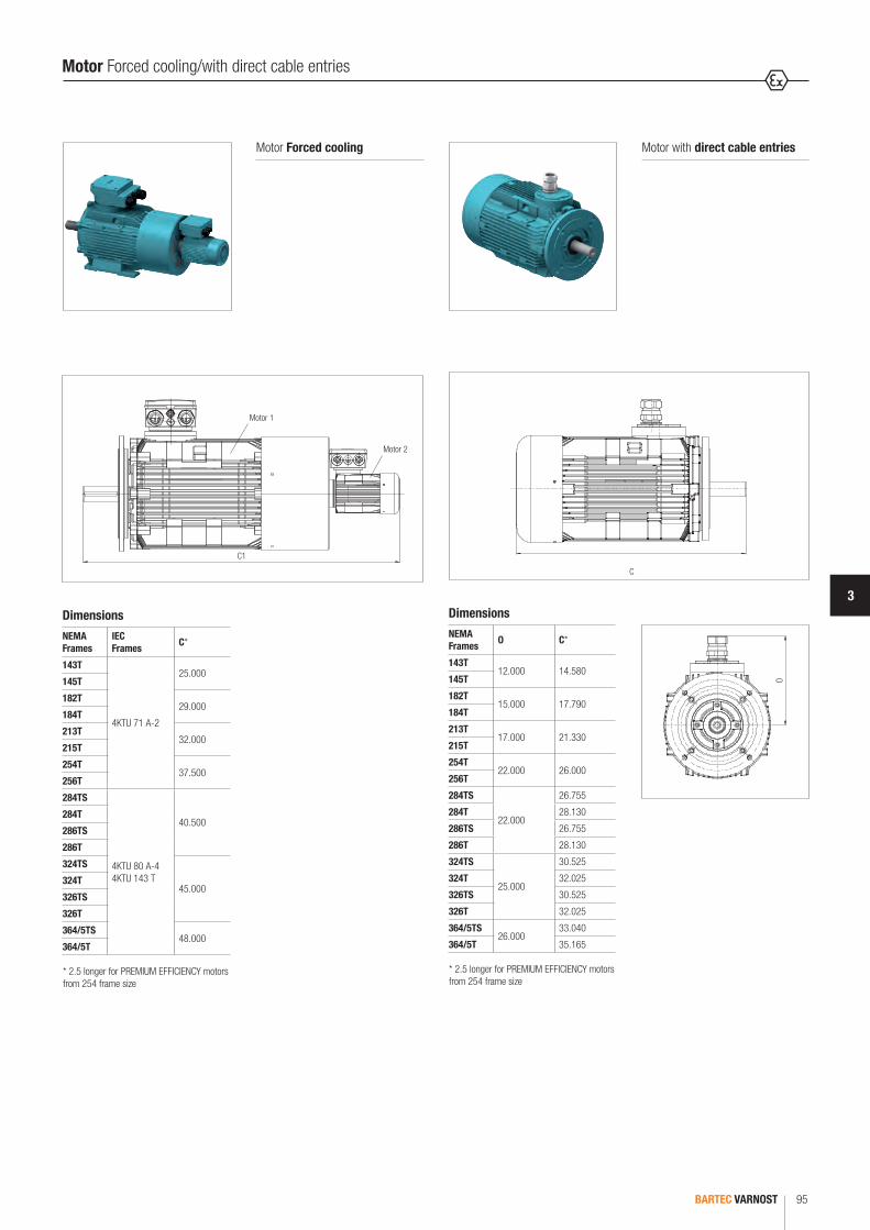
3
BARTEC VARNOST 95
Motor Forced cooling
DimensionsNEMA Frames
IEC Frames C*
143T
4KTU 71 A-2
25.000145T
182T29.000
184T
213T32.000
215T
254T37.500
256T
284TS
4KTU 80 A-4 4KTU 143 T
40.500284T
286TS
286T
324TS
45.000324T
326TS
326T
364/5TS48.000
364/5T
C1
Motor 1
Motor 2
* 2.5 longer for PREMIUM EFFICIENCY motors from 254 frame size
Motor Forced cooling/with direct cable entries
Motor with direct cable entries
DimensionsNEMA Frames O C*
143T12.000 14.580
145T
182T15.000 17.790
184T
213T17.000 21.330
215T
254T22.000 26.000
256T
284TS
22.000
26.755
284T 28.130
286TS 26.755
286T 28.130
324TS
25.000
30.525
324T 32.025
326TS 30.525
326T 32.025
364/5TS26.000
33.040
364/5T 35.165
C
O
* 2.5 longer for PREMIUM EFFICIENCY motors from 254 frame size
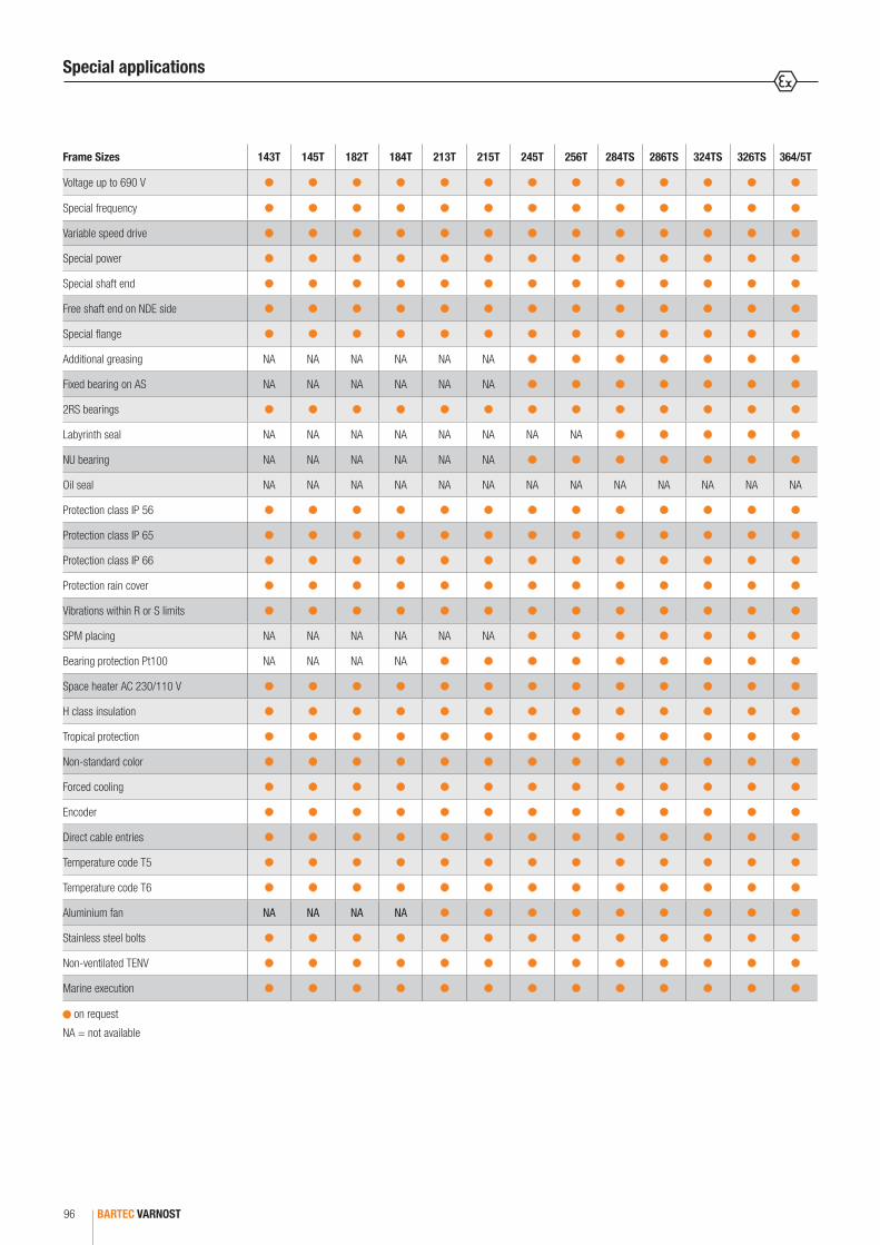
BARTEC VARNOST96
Frame Sizes 143T 145T 182T 184T 213T 215T 245T 256T 284TS 286TS 324TS 326TS 364/5T
Voltage up to 690 V
Special frequency
Variable speed drive
Special power
Special shaft end
Free shaft end on NDE side
Special flange
Additional greasing NA NA NA NA NA NA
Fixed bearing on AS NA NA NA NA NA NA
2RS bearings
Labyrinth seal NA NA NA NA NA NA NA NA
NU bearing NA NA NA NA NA NA
Oil seal NA NA NA NA NA NA NA NA NA NA NA NA NA
Protection class IP 56
Protection class IP 65
Protection class IP 66
Protection rain cover
Vibrations within R or S limits
SPM placing NA NA NA NA NA NA
Bearing protection Pt100 NA NA NA NA
Space heater AC 230/110 V
H class insulation
Tropical protection
Non-standard color
Forced cooling
Encoder
Direct cable entries
Temperature code T5
Temperature code T6
Aluminium fan NA NA NA NA
Stainless steel bolts
Non-ventilated TENV
Marine execution
on request
NA = not available
Special applications

SUBMERSIBLE MOTORS, SERIES 4 KTS
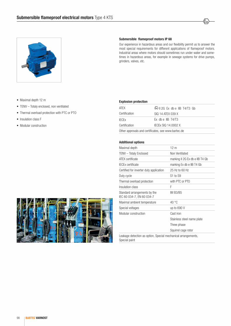
BARTEC VARNOST98
Submersible flameproof electrical motors Type 4 KTS
Submersible flameproof motors IP 68
Our experience in hazardous areas and our flexibility permit us to answer the most special requirements for different applications of flameproof motors. Industrial areas where motors should sometimes run under water and some-times in hazardous areas, for example in sewage systems for drive pumps, grinders, valves, etc.
• Maximal depth 12 m
• TENV – Totaly enclosed, non ventilated
• Thermal overload protection with PTC or PTO
• Insulation class F
• Modular construction
Additional options
Maximal depth 12 m
TENV – Totaly Enclosed Non Ventilated
ATEX certificate marking II 2G Ex db e IIB T4 Gb
IECEx certificate marking Ex db e IIB T4 Gb
Certified for inverter duty application 25 Hz to 60 Hz
Duty cycle S1 to S9
Thermal overload protection with PTC or PTO
Insulation class F
Standard arrangements by the IEC 60 034-7, EN 60 034-7
IM B3/B5
Maximal ambient temperature 40 °C
Special voltages up to 690 V
Modular construction Cast iron
Stainless steel name plate
Three phase
Squirrel cage rotor
Leakage detection as option, Special mechanical arrangements, Special paint
Explosion protection
ATEX
Certification II 2G Ex db e IIB T4/T3 Gb
SIQ 14 ATEX 039 X
IECEx
Certification
Ex db e IIB T4/T3
IECEx SIQ 14.0002 X
Other approvals and certificates, see www.bartec.de

4
BARTEC VARNOST 99
Submersible flameproof electrical motors Type 4 KTS
DimensionsFrame size Flange D E F G HB L LA M N P S No. of
fixing holes
T
4KTS 90 S, L F 165-I 24 50 8 27 181 323 10 165 130 200 12 4 3.5
4KTS 100 L F 215-I 28 60 8 31 188 358 11 215 180 250 14 4 4
4KTS 132 S, M F 265-I 38 80 10 41 218 469 12 265 230 300 14 4 4
4KTS 160M, L F 300-I 42 110 12 45 276 604 15 300 250 350 18 4 5
4KTS 180 M, L F 300-I 48 110 14 51 316 627 15 300 250 350 18 4 5
N
L
MP D F
HB
S4 x 90°
45°
E
E
TLA


BARTEC 03-0330-0707/A-10/2017-BAT-344828/2 101
MINING MOTORS, SERIES 4KTCR AND 4KTCP


FLAMEPROOF MOTORSCast iron enclosure
4KTCR 71-225, 5KTCR 250-315
104 - 108
Welded enclosure
3KTCR 180-225, 4KTCR 250-315, 5KTCR 355
109 - 113
Motors for heavy working conditions
3KTCP 180-225, 4KTCP 250-315, 5KTCP 355
114 - 115
Motors with electric brake
4KTCR 71-225, 5KTCR 250-280
116
MOTORS WITH ADDITIONAL COOLING FOR VARIABLE SPEED DRIVE 117
MOTORS WITH SOCKET 118
MOTORS FOR AXIAL FANS 118
DIMENSIONSCast iron enclosure
4KTCR 71-225, 5KTCR 250-315
119 - 121
Welded enclosure
3KTCR 180-225, 4KTCR 250-315, 5KTCR 355
122 - 124
Motors for heavy working conditions
3KTCP 180-225, 4KTCP 250-315, 5KTCP 355
125 - 126
SPECIAL APPLICATIONS/OPTIONS 127
CONTENTS
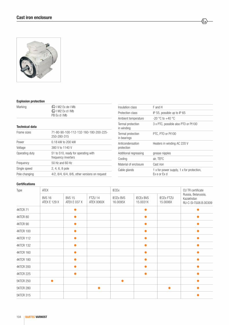
BARTEC VARNOST104
Certifications
Type ATEX IECEx CU TR certificate Russia, Belarussia, Kazakhstan RU-C-SI-ГБ08.B.00309
BVS 16 ATEX E 129 X
BVS 15 ATEX E 037 X
FTZU 14 ATEX 0060X
IECEx BVS 16.0095X
IECEx BVS 15.0031X
IECEx FTZU 15.0006X
4KTCR 71
4KTCR 80
4KTCR 90
4KTCR 100
4KTCR 112
4KTCR 132
4KTCR 160
4KTCR 180
4KTCR 200
4KTCR 225
5KTCR 250
5KTCR 280
5KTCR 315
Technical data
Frame sizes 71-80-90-100-112-132-160-180-200-225- 250-280-315
Power 0.18 kW to 200 kW
Voltage 380 V to 1140 V
Operating duty S1 to S10, ready for operating with frequency inverters
Frequency 50 Hz and 60 Hz
Single speed 2, 4, 6, 8 pole
Pole changing 4/2, 8/4, 6/4, 8/6, other versions on request
Insulation class F and H
Protection class IP 55, possible up to IP 65
Ambient temperature -20 °C to +40 °C
Termal protection in winding
3 x PTC, possible also PTO or Pt100
Termal protection in bearings
PTC, PTO or Pt100
Anticondensation protection
Heaters in winding AC 220 V
Additional regreasing grease nipples
Cooling air, TEFC
Material of enclosure Cast iron
Cable glands 1 x for power supply, 1 x for protection, Ex e or Ex d
Explosion protection
Marking I M2 Ex de I Mb I M2 Ex d I Mb
PB Ex d I Mb
Cast iron enclosure
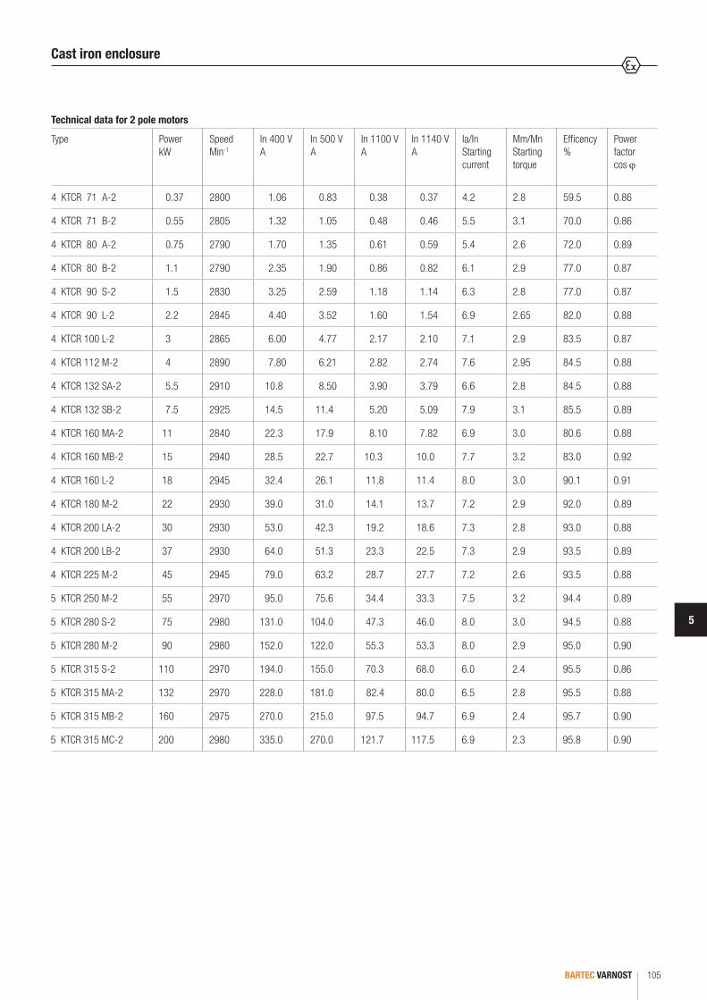
5
BARTEC VARNOST 105
Technical data for 2 pole motors
Type Power kW
Speed Min-1
In 400 V A
In 500 V A
In 1100 V A
In 1140 V A
Ia/In Starting current
Mm/Mn Starting torque
Efficency %
Power factor cos ϕ
4 KTCR 71 A-2 0.37 2800 1.06 0.83 0.38 0.37 4.2 2.8 59.5 0.86
4 KTCR 71 B-2 0.55 2805 1.32 1.05 0.48 0.46 5.5 3.1 70.0 0.86
4 KTCR 80 A-2 0.75 2790 1.70 1.35 0.61 0.59 5.4 2.6 72.0 0.89
4 KTCR 80 B-2 1.1 2790 2.35 1.90 0.86 0.82 6.1 2.9 77.0 0.87
4 KTCR 90 S-2 1.5 2830 3.25 2.59 1.18 1.14 6.3 2.8 77.0 0.87
4 KTCR 90 L-2 2.2 2845 4.40 3.52 1.60 1.54 6.9 2.65 82.0 0.88
4 KTCR 100 L-2 3 2865 6.00 4.77 2.17 2.10 7.1 2.9 83.5 0.87
4 KTCR 112 M-2 4 2890 7.80 6.21 2.82 2.74 7.6 2.95 84.5 0.88
4 KTCR 132 SA-2 5.5 2910 10.8 8.50 3.90 3.79 6.6 2.8 84.5 0.88
4 KTCR 132 SB-2 7.5 2925 14.5 11.4 5.20 5.09 7.9 3.1 85.5 0.89
4 KTCR 160 MA-2 11 2840 22.3 17.9 8.10 7.82 6.9 3.0 80.6 0.88
4 KTCR 160 MB-2 15 2940 28.5 22.7 10.3 10.0 7.7 3.2 83.0 0.92
4 KTCR 160 L-2 18 2945 32.4 26.1 11.8 11.4 8.0 3.0 90.1 0.91
4 KTCR 180 M-2 22 2930 39.0 31.0 14.1 13.7 7.2 2.9 92.0 0.89
4 KTCR 200 LA-2 30 2930 53.0 42.3 19.2 18.6 7.3 2.8 93.0 0.88
4 KTCR 200 LB-2 37 2930 64.0 51.3 23.3 22.5 7.3 2.9 93.5 0.89
4 KTCR 225 M-2 45 2945 79.0 63.2 28.7 27.7 7.2 2.6 93.5 0.88
5 KTCR 250 M-2 55 2970 95.0 75.6 34.4 33.3 7.5 3.2 94.4 0.89
5 KTCR 280 S-2 75 2980 131.0 104.0 47.3 46.0 8.0 3.0 94.5 0.88
5 KTCR 280 M-2 90 2980 152.0 122.0 55.3 53.3 8.0 2.9 95.0 0.90
5 KTCR 315 S-2 110 2970 194.0 155.0 70.3 68.0 6.0 2.4 95.5 0.86
5 KTCR 315 MA-2 132 2970 228.0 181.0 82.4 80.0 6.5 2.8 95.5 0.88
5 KTCR 315 MB-2 160 2975 270.0 215.0 97.5 94.7 6.9 2.4 95.7 0.90
5 KTCR 315 MC-2 200 2980 335.0 270.0 121.7 117.5 6.9 2.3 95.8 0.90
Cast iron enclosure
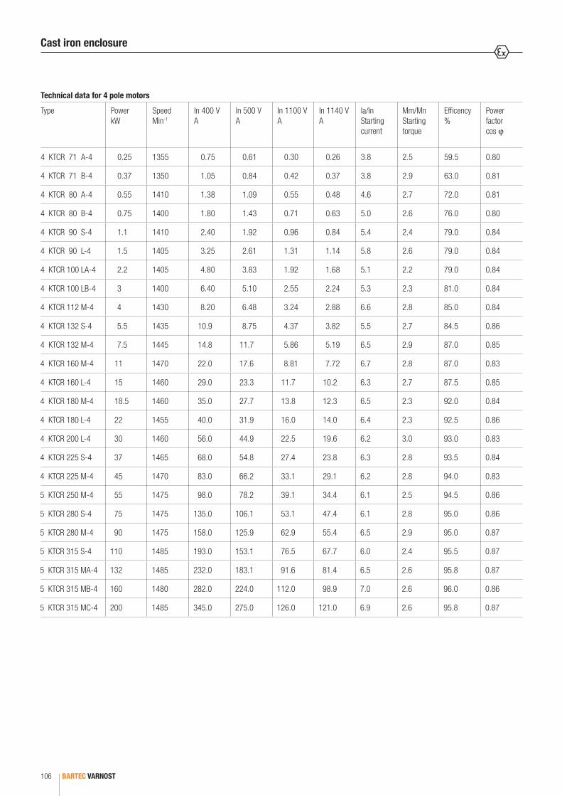
BARTEC VARNOST106
Technical data for 4 pole motors
Type Power kW
Speed Min-1
In 400 V A
In 500 V A
In 1100 V A
In 1140 V A
Ia/In Starting current
Mm/Mn Starting torque
Efficency %
Power factor cos ϕ
4 KTCR 71 A-4 0.25 1355 0.75 0.61 0.30 0.26 3.8 2.5 59.5 0.80
4 KTCR 71 B-4 0.37 1350 1.05 0.84 0.42 0.37 3.8 2.9 63.0 0.81
4 KTCR 80 A-4 0.55 1410 1.38 1.09 0.55 0.48 4.6 2.7 72.0 0.81
4 KTCR 80 B-4 0.75 1400 1.80 1.43 0.71 0.63 5.0 2.6 76.0 0.80
4 KTCR 90 S-4 1.1 1410 2.40 1.92 0.96 0.84 5.4 2.4 79.0 0.84
4 KTCR 90 L-4 1.5 1405 3.25 2.61 1.31 1.14 5.8 2.6 79.0 0.84
4 KTCR 100 LA-4 2.2 1405 4.80 3.83 1.92 1.68 5.1 2.2 79.0 0.84
4 KTCR 100 LB-4 3 1400 6.40 5.10 2.55 2.24 5.3 2.3 81.0 0.84
4 KTCR 112 M-4 4 1430 8.20 6.48 3.24 2.88 6.6 2.8 85.0 0.84
4 KTCR 132 S-4 5.5 1435 10.9 8.75 4.37 3.82 5.5 2.7 84.5 0.86
4 KTCR 132 M-4 7.5 1445 14.8 11.7 5.86 5.19 6.5 2.9 87.0 0.85
4 KTCR 160 M-4 11 1470 22.0 17.6 8.81 7.72 6.7 2.8 87.0 0.83
4 KTCR 160 L-4 15 1460 29.0 23.3 11.7 10.2 6.3 2.7 87.5 0.85
4 KTCR 180 M-4 18.5 1460 35.0 27.7 13.8 12.3 6.5 2.3 92.0 0.84
4 KTCR 180 L-4 22 1455 40.0 31.9 16.0 14.0 6.4 2.3 92.5 0.86
4 KTCR 200 L-4 30 1460 56.0 44.9 22.5 19.6 6.2 3.0 93.0 0.83
4 KTCR 225 S-4 37 1465 68.0 54.8 27.4 23.8 6.3 2.8 93.5 0.84
4 KTCR 225 M-4 45 1470 83.0 66.2 33.1 29.1 6.2 2.8 94.0 0.83
5 KTCR 250 M-4 55 1475 98.0 78.2 39.1 34.4 6.1 2.5 94.5 0.86
5 KTCR 280 S-4 75 1475 135.0 106.1 53.1 47.4 6.1 2.8 95.0 0.86
5 KTCR 280 M-4 90 1475 158.0 125.9 62.9 55.4 6.5 2.9 95.0 0.87
5 KTCR 315 S-4 110 1485 193.0 153.1 76.5 67.7 6.0 2.4 95.5 0.87
5 KTCR 315 MA-4 132 1485 232.0 183.1 91.6 81.4 6.5 2.6 95.8 0.87
5 KTCR 315 MB-4 160 1480 282.0 224.0 112.0 98.9 7.0 2.6 96.0 0.86
5 KTCR 315 MC-4 200 1485 345.0 275.0 126.0 121.0 6.9 2.6 95.8 0.87
Cast iron enclosure

5
BARTEC VARNOST 107
Technical data for 6 pole motors
Type Power kW
Speed Min-1
In 400 V A
In 500 V A
In 1100 V A
In 1140 V A
Ia/In Starting current
Mm/Mn Starting torque
Efficency %
Power factor cos ϕ
4 KTCR 71 A-6 0.18 930 0.67 0.54 0.24 0.24 3.1 2.3 60.0 0.65
4 KTCR 71 B-6 0.25 940 0.85 0.68 0.31 0.30 3.7 2.5 64.0 0.67
4 KTCR 80 A-6 0.37 925 1.1 0.88 0.40 0.39 3.6 2.5 67.0 0.72
4 KTCR 80 B-6 0.55 915 1.5 1.20 0.55 0.53 4.1 2.5 72.0 0.74
4 KTCR 90 S-6 0.75 915 2.1 1.68 0.76 0.74 3.7 2.1 70.0 0.74
4 KTCR 90 L-6 1.1 915 3.0 2.40 1.09 1.05 4.1 2.3 73.0 0.73
4 KTCR 100 L-6 1.5 930 3.7 2.96 1.35 1.30 4.7 2.3 76.0 0.77
4 KTCR 112 M-6 2.2 960 5.0 4.00 1.82 1.75 6.1 2.7 82.0 0.78
4 KTCR 132 S-6 3 975 6.6 5.28 2.40 2.32 6.3 2.5 83.5 0.79
4 KTCR 132 MA-6 4 960 8.8 7.04 3.20 3.09 6.3 2.9 83.0 0.80
4 KTCR 132 MB-6 5.5 955 11.8 9.44 4.29 4.14 6.1 2.9 83.5 0.81
4 KTCR 160 M-6 7.5 970 15.8 12.6 5.75 5.54 6.7 2.4 86.0 0.80
4 KTCR 160 L-6 11 965 23.5 18.8 8.55 8.25 6.0 2.3 88.5 0.77
4 KTCR 180 L-6 15 965 31.0 24.8 11.3 10.9 5.2 2.3 89.5 0.78
4 KTCR 200 LA-6 18.5 965 36.0 28.8 13.1 12.6 6.0 2.4 91.0 0.81
4 KTCR 200 LB-6 22 965 43.0 34.4 15.6 15.1 6.0 2.4 91.5 0.81
4 KTCR 225 M-6 30 975 56.0 44.8 20.4 19.6 5.8 2.5 92.5 0.83
5 KTCR 250 M-6 37 985 69.0 55.2 25.1 24.2 6.0 2.6 93.5 0.83
5 KTCR 280 S-6 45 985 82.0 65.6 29.8 28.8 6.3 2.7 94.5 0.84
5 KTCR 280 M-6 55 985 101.0 80.8 36.7 35.4 6.0 2.8 94.5 0.84
5 KTCR 315 S-6 75 980 140.0 112.0 50.9 49.1 5.9 2.8 95.0 0.82
5 KTCR 315 MA-6 90 985 163.0 130.4 59.3 57.2 5.1 2.9 95.5 0.84
5 KTCR 315 MB-6 110 990 198.0 158.4 72.0 69.5 6.5 2.4 91.5 0.88
5 KTCR 315 L-6 132 990 238.0 190.4 86.5 83.5 6.8 2.4 90.5 0.88
Cast iron enclosure

BARTEC VARNOST108
Technical data for 8 pole motors
Type Power kW
Speed Min-1
In 400 V A
In 500 V A
In 1100 V A
In 1140 V A
Ia/In Starting current
Mm/Mn Starting torque
Efficency %
Power factor cos ϕ
4 KTCR 71 A-8 0.09 680 0.74 0.59 0.27 0.26 2.0 2.1 38.0 0.51
4 KTCR 71 B-8 0.12 655 0.59 0.48 0.22 0.21 2.4 2.1 45.0 0.71
4 KTCR 80 A-8 0.18 680 0.73 0.58 0.26 0.25 2.9 2.2 61.0 0.65
4 KTCR 80 B-8 0.25 680 1.01 0.81 0.37 0.36 3.1 2.3 58.0 0.68
4 KTCR 90 S-8 0.37 685 1.38 1.10 0.50 0.48 3.0 2.0 66.0 0.65
4 KTCR 90 L-8 0.55 685 1.93 1.54 0.70 0.68 3.1 2.1 69.0 0.66
4 KTCR 100 LA-8 0.75 690 2.53 2.02 0.92 0.89 3.5 2.1 69.0 0.69
4 KTCR 100 LB-8 1.1 695 3.58 2.86 1.30 1.25 3.8 2.2 70.0 0.70
4 KTCR 112 M-8 1.5 710 4.57 3.65 1.66 1.60 4.3 2.5 78.0 0.67
4 KTCR 132 S-8 2.2 710 6.05 4.84 2.20 2.12 4.3 2.2 79.0 0.74
4 KTCR 132 M-8 3.0 710 7.92 6.34 2.88 2.78 4.8 2.3 80.0 0.76
4 KTCR 160 MA-8 4.0 720 11.0 8.80 4.00 3.86 4.8 2.3 82.6 0.71
4 KTCR 160 MB-8 5.5 715 14.7 11.8 5.36 5.17 4.8 2.1 84.0 0.71
4 KTCR 160 L-8 7.5 725 18.4 14.7 6.68 6.45 5.8 2.1 86.5 0.75
4 KTCR 180 L-8 11.0 715 27.5 22.0 10.0 9.65 4.2 2.5 86.7 0.74
4 KTCR 200 L-8 15.0 720 31.9 25.5 11.6 11.2 4.5 2.5 91.0 0.82
4 KTCR 225 S-8 18.5 710 40.7 32.6 14.8 14.3 4.6 2.6 91.0 0.79
4 KTCR 225 M-8 22.0 715 49.5 39.6 18.0 17.4 4.6 2.6 91.5 0.77
5 KTCR 250 M-8 30.0 730 64.9 51.9 23.6 22.8 5.4 2.4 92.8 0.79
5 KTCR 280 S-8 37.0 730 81.4 65.1 29.6 28.6 6.0 2.3 93.0 0.78
5 KTCR 280 M-8 45.0 735 99.0 79.2 36.0 34.7 6.4 2.7 93.5 0.78
5 KTCR 315 S-8 55.0 735 114.4 91.5 41.6 40.1 6.2 2.3 94.5 0.81
5 KTCR 315 MA-8 75.0 740 154.0 123.2 56.0 54.0 6.3 2.1 94.5 0.82
5 KTCR 315 MB-8 90.0 740 190.3 152.2 69.2 66.8 6.7 2.5 91.1 0.83
5 KTCR 315 L-8 110.0 740 234.3 187.4 85.2 82.2 6.9 2.5 90.0 0.83
Cast iron enclosure

5
BARTEC VARNOST 109
Welded enclosure
Technical data
Frame sizes 180-200-225-250-280-315-355
Power 22 kW to 400 kW
Voltage 380 V to 1140 V
Operating duty S1 to S10, ready for operating with frequency inverters
Frequency 50 Hz and 60 Hz
Single speed 2, 4, 6, 8 pole
Pole changing 4/2, 8/4, 6/4, 8/6, other versions on request
Insulation class F and H
Protection class IP 55, possible up to IP 65
Ambient temperature -20 °C to +40 °C
Termal protection in winding
3 x PTC, possible also PTO or Pt100
Termal protection in bearings
PTC, PTO or Pt100
Anticondensation protection
Heaters in winding AC 220 V
Additional regreasing grease nipples
Cooling air, TEFC
Material of enclosure welded steel plates
Cable glands 1 x for power supply, 1 x for protection, Ex e or Ex d
Explosion protection
Marking I M2 Ex de I Mb, I M2 Ex dbe I Mb I M2 Ex d I Mb, I M2 Ex db I Mb
PB Ex d I Mb
Certifications
Type ATEX IECEx CU TR certificate Russia, Belarussia, Kazakhstan RU-C-SI-ГБ08.B.00309BVS 15 ATEX E 075 X FTZU 13 ATEX 0111X IECEx BVS 15.0066X IECEx FTZU 14.0006X
3KTCR 180
3KTCR 200
3KTCR 225
4KTCR 250
4KTCR 280
4KTCR 315
5KTCR 355

BARTEC VARNOST110
Technical data for 2 pole motors
Type Power kW
Speed Min-1
In 400 V A
In 500 V A
In 1100 V A
In 1140 V A
Ia/In Starting current
Mm/Mn Starting torque
Efficency %
Power factor cos ϕ
3 KTCR 180 M-2 22 2930 39.0 31.0 14.1 13.7 7.2 2.9 92.0 0.89
3 KTCR 200 LA-2 30 2930 53.0 42.3 19.2 18.6 7.3 2.8 93.0 0.88
3 KTCR 200 LB-2 37 2930 64.0 51.3 23.3 22.5 7.3 2.9 93.5 0.89
3 KTCR 225 M-2 45 2945 79.0 63.2 28.7 27.7 7.2 2.6 93.5 0.88
4 KTCR 250 M-2 55 2970 95.0 75.6 34.4 33.3 7.5 3.2 94.4 0.89
4 KTCR 280 S-2 75 2980 131.0 104.0 47.3 46.0 8.0 3.0 94.5 0.88
4 KTCR 280 M-2 90 2980 152.0 122.0 55.3 53.3 8.0 2.9 95.0 0.90
4 KTCR 315 S-2 110 2970 194.0 155.0 70.3 68.0 6.0 2.4 95.5 0.86
4 KTCR 315 MA-2 132 2970 228.0 181.0 82.4 80.0 6.5 2.8 95.5 0.88
4 KTCR 315 MB-2 160 2975 270.0 215.0 97.5 94.7 6.9 2.4 95.7 0.90
4 KTCR 315 MC-2 200 2980 335.0 270.0 121.7 117.5 6.9 2.3 95.8 0.90
5 KTCR 355 SA-2 200 2980 330.0 264.0 120.0 115.8 7.2 2.5 95.6 0.92
5 KTCR 355 SB-2 250 2985 414 331.2 150.5 145.3 7.4 2.5 95.2 0.92
5 KTCR 355 LA-2 280 2985 463.7 371 168.6 162.7 7.3 2.4 95.4 0.91
5 KTCR 355 LB-2 315 2985 517 413.6 188 181.4 7.4 2.5 95.5 0.92
Welded enclosure
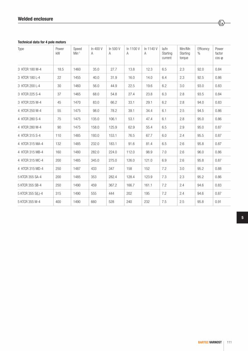
5
BARTEC VARNOST 111
Technical data for 4 pole motors
Type Power kW
Speed Min-1
In 400 V A
In 500 V A
In 1100 V A
In 1140 V A
Ia/In Starting current
Mm/Mn Starting torque
Efficency %
Power factor cos ϕ
3 KTCR 180 M-4 18.5 1460 35.0 27.7 13.8 12.3 6.5 2.3 92.0 0.84
3 KTCR 180 L-4 22 1455 40.0 31.9 16.0 14.0 6.4 2.3 92.5 0.86
3 KTCR 200 L-4 30 1460 56.0 44.9 22.5 19.6 6.2 3.0 93.0 0.83
3 KTCR 225 S-4 37 1465 68.0 54.8 27.4 23.8 6.3 2.8 93.5 0.84
3 KTCR 225 M-4 45 1470 83.0 66.2 33.1 29.1 6.2 2.8 94.0 0.83
4 KTCR 250 M-4 55 1475 98.0 78.2 39.1 34.4 6.1 2.5 94.5 0.86
4 KTCR 280 S-4 75 1475 135.0 106.1 53.1 47.4 6.1 2.8 95.0 0.86
4 KTCR 280 M-4 90 1475 158.0 125.9 62.9 55.4 6.5 2.9 95.0 0.87
4 KTCR 315 S-4 110 1485 193.0 153.1 76.5 67.7 6.0 2.4 95.5 0.87
4 KTCR 315 MA-4 132 1485 232.0 183.1 91.6 81.4 6.5 2.6 95.8 0.87
4 KTCR 315 MB-4 160 1480 282.0 224.0 112.0 98.9 7.0 2.6 96.0 0.86
4 KTCR 315 MC-4 200 1485 345.0 275.0 126.0 121.0 6.9 2.6 95.8 0.87
4 KTCR 315 MD-4 250 1487 433 347 158 152 7.2 3.0 95.2 0.88
5 KTCR 355 SA-4 200 1485 353 282.4 128.4 123.9 7.3 2.3 95.2 0.86
5 KTCR 355 SB-4 250 1490 459 367.2 166.7 161.1 7.2 2.4 94.6 0.83
5 KTCR 355 S(L)-4 315 1490 555 444 202 195 7.2 2.4 94.6 0.87
5 KTCR 355 M-4 400 1490 660 528 240 232 7.5 2.5 95.8 0.91
Welded enclosure
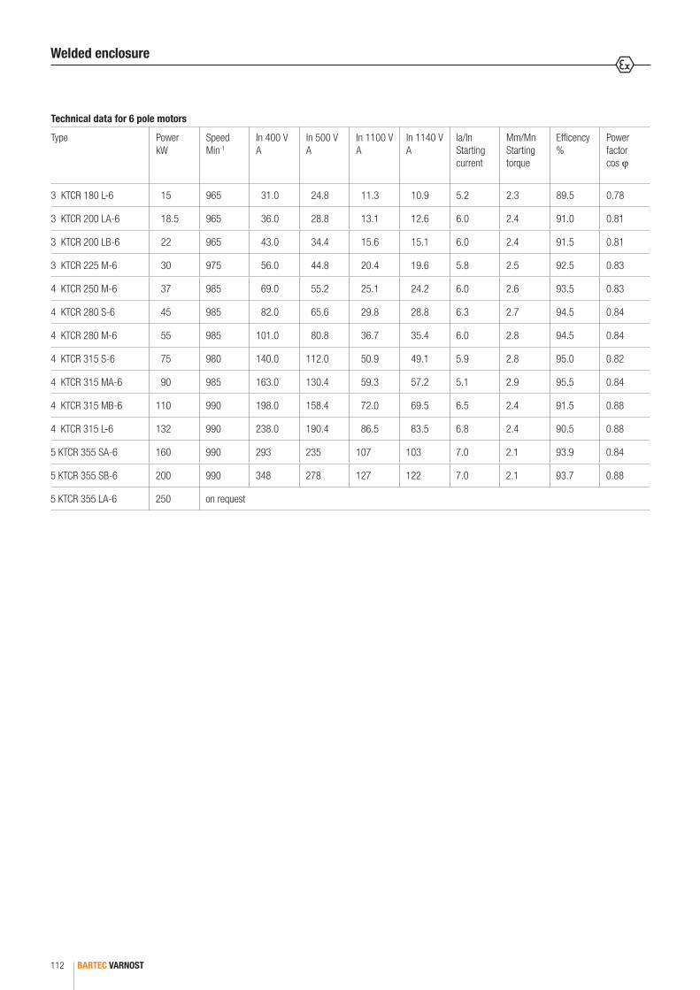
BARTEC VARNOST112
Technical data for 6 pole motors
Type Power kW
Speed Min-1
In 400 V A
In 500 V A
In 1100 V A
In 1140 V A
Ia/In Starting current
Mm/Mn Starting torque
Efficency %
Power factor cos ϕ
3 KTCR 180 L-6 15 965 31.0 24.8 11.3 10.9 5.2 2.3 89.5 0.78
3 KTCR 200 LA-6 18.5 965 36.0 28.8 13.1 12.6 6.0 2.4 91.0 0.81
3 KTCR 200 LB-6 22 965 43.0 34.4 15.6 15.1 6.0 2.4 91.5 0.81
3 KTCR 225 M-6 30 975 56.0 44.8 20.4 19.6 5.8 2.5 92.5 0.83
4 KTCR 250 M-6 37 985 69.0 55.2 25.1 24.2 6.0 2.6 93.5 0.83
4 KTCR 280 S-6 45 985 82.0 65.6 29.8 28.8 6.3 2.7 94.5 0.84
4 KTCR 280 M-6 55 985 101.0 80.8 36.7 35.4 6.0 2.8 94.5 0.84
4 KTCR 315 S-6 75 980 140.0 112.0 50.9 49.1 5.9 2.8 95.0 0.82
4 KTCR 315 MA-6 90 985 163.0 130.4 59.3 57.2 5.1 2.9 95.5 0.84
4 KTCR 315 MB-6 110 990 198.0 158.4 72.0 69.5 6.5 2.4 91.5 0.88
4 KTCR 315 L-6 132 990 238.0 190.4 86.5 83.5 6.8 2.4 90.5 0.88
5 KTCR 355 SA-6 160 990 293 235 107 103 7.0 2.1 93.9 0.84
5 KTCR 355 SB-6 200 990 348 278 127 122 7.0 2.1 93.7 0.88
5 KTCR 355 LA-6 250 on request
Welded enclosure

5
BARTEC VARNOST 113
Technical data for 8 pole motors
Type Power kW
Speed Min-1
In 400 V A
In 500 V A
In 1100 V A
In 1140 V A
Ia/In Starting current
Mm/Mn Starting torque
Efficency %
Power factor cos ϕ
4 KTCR 160 L-8 7.5 725 18.4 14.7 6.68 6.45 5.8 2.1 86.5 0.75
3 KTCR 180 L-8 11.0 715 27.5 22.0 10.0 9.65 4.2 2.5 86.7 0.74
3 KTCR 200 L-8 15.0 720 31.9 25.5 11.6 11.2 4.5 2.5 91.0 0.82
3 KTCR 225 S-8 18.5 710 40.7 32.6 14.8 14.3 4.6 2.6 91.0 0.79
3 KTCR 225 M-8 22.0 715 49.5 39.6 18.0 17.4 4.6 2.6 91.5 0.77
4 KTCR 250 M-8 30.0 730 64.9 51.9 23.6 22.8 5.4 2.4 92.8 0.79
4 KTCR 280 S-8 37.0 730 81.4 65.1 29.6 28.6 6.0 2.3 93.0 0.78
4 KTCR 280 M-8 45.0 735 99.0 79.2 36.0 34.7 6.4 2.7 93.5 0.78
4 KTCR 315 S-8 55.0 735 114.4 91.5 41.6 40.1 6.2 2.3 94.5 0.81
4 KTCR 315 MA-8 75.0 740 154.0 123.2 56.0 54.0 6.3 2.1 94.5 0.82
4 KTCR 315 MB-8 90.0 740 190.3 152.2 69.2 66.8 6.7 2.5 91.1 0.83
4 KTCR 315 L-8 110.0 740 234.3 187.4 85.2 82.2 6.9 2.5 90.0 0.83
5 KTCR 355 SA-8 132 740 256 205 93.1 89.8 6.9 2.2 93.2 0.80
5 KTCR 355 SB-8 160 740 323 258 118 113 6.9 2.2 93.8 0.76
5 KTCR 355 LA-8 200on request
5 KTCR 355 LB-8 250
Welded enclosure
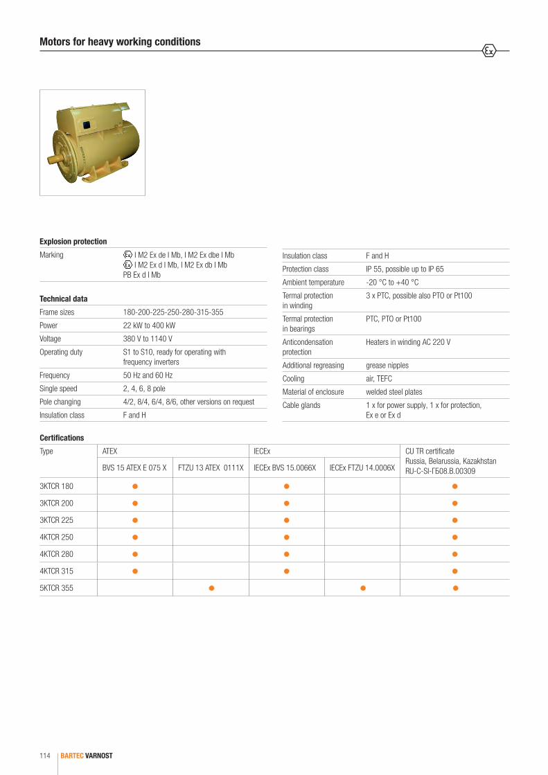
BARTEC VARNOST114
Motors for heavy working conditions
Technical data
Frame sizes 180-200-225-250-280-315-355
Power 22 kW to 400 kW
Voltage 380 V to 1140 V
Operating duty S1 to S10, ready for operating with frequency inverters
Frequency 50 Hz and 60 Hz
Single speed 2, 4, 6, 8 pole
Pole changing 4/2, 8/4, 6/4, 8/6, other versions on request
Insulation class F and H
Insulation class F and H
Protection class IP 55, possible up to IP 65
Ambient temperature -20 °C to +40 °C
Termal protection in winding
3 x PTC, possible also PTO or Pt100
Termal protection in bearings
PTC, PTO or Pt100
Anticondensation protection
Heaters in winding AC 220 V
Additional regreasing grease nipples
Cooling air, TEFC
Material of enclosure welded steel plates
Cable glands 1 x for power supply, 1 x for protection, Ex e or Ex d
Explosion protection
Marking I M2 Ex de I Mb, I M2 Ex dbe I Mb I M2 Ex d I Mb, I M2 Ex db I Mb
PB Ex d I Mb
Certifications
Type ATEX IECEx CU TR certificate Russia, Belarussia, Kazakhstan RU-C-SI-ГБ08.B.00309BVS 15 ATEX E 075 X FTZU 13 ATEX 0111X IECEx BVS 15.0066X IECEx FTZU 14.0006X
3KTCR 180
3KTCR 200
3KTCR 225
4KTCR 250
4KTCR 280
4KTCR 315
5KTCR 355

5
BARTEC VARNOST 115
Technical data for 4 pole motors
Type Power kW
Speed Min-1
In 400 V A
In 500 V A
In 1100 V A
In 1140 V A
Ia/In Starting current
Mm/Mn Starting torque
Efficency %
Power factor cos ϕ
3 KTCP 180 L-4 22 1455 44 34.5 15.3 15.3 5.0 2.2 89 0.84
3 KTCP 200 L-4 30 1460 54 45 20.2 19.0 4.7 2.3 90 0.85
3 KTCP 225 M-4 45 1465 81 65 29.2 28.5 4.8 2.5 91 0.86
3 KTCP 225 S-4 37 1470 68 54 24.3 23.7 4.8 2.5 92 0.86
4 KTCP 250 M-4 55 1475 103 82 38.2 36.0 4.8 2.5 92.5 0.86
4 KTCP 280 S-4 75 1475 134 108 48.6 47.0 4.9 2.4 93 0.87
4 KTCP 280 M-4 90 1475 162 129 58.5 56.7 4.8 2.4 92.5 0.88
4 KTCP 315 S-4 110 1485 201 161 72 70.7 5.0 2.4 93 0.88
4 KTCP 315 MA-4 132 1485 240 184 82.8 84.3 5.0 2.4 93 0.88
4 KTCP 315 MB-4 160 1480 280 224 100.8 98.3 5.5 2.4 93.5 0.89
4 KTCP 315 MC-4 200 1485 328 275 126.0 115.0 6.9 2.6 95.8 0.87
4 KTCP 315 MD-4 250 1487 433 347 158 152 7.2 3.0 95.2 0.88
5 KTCP 355 SA-4 200 1485 353 282.4 128.4 123.9 7.3 2.3 95.2 0.86
5 KTCP 355 SB-4 250 1490 459 367.2 166.7 161.1 7.2 2.4 94.6 0.83
5 KTCP 355 S(L)-4 315 1490 555 444 202 195 7.2 2.4 94.6 0.87
5 KTCP 355 M-4 400 1490 660 528 240 232 7.5 2.5 95.8 0.91
Data for 2, 6 and 8 pole motors on request
Motors for heavy working conditions

BARTEC VARNOST116
Motors with electric brake
Technical data
Frame sizes 71-80-90-100-112-132-160-180-200-225- 250-280
Power 0.18 kW to 90 kW
Voltage Motors 380 V to 1140 V Brake AC 230 V or 400 V
Brake torque 8 to 2000 Nm
Operating duty S1 to S10, ready for operating with frequency inverters
Frequency 50 Hz and 60 Hz
Single speed 2, 4, 6, 8 pole
Pole changing 4/2, 8/4, 6/4, 8/6, other on request
Insulation class F and H
Protection class IP 55, possible up to IP 65
Ambient temperature -20 °C to +40 °C
Termal protection in winding
3 x PTC, possible also PTO or Pt100
Termal protection in bearings
PTC, PTO or Pt100
Anticondensation protection
Heaters in winding AC 220 V
Additional regreasing grease nipples
Cooling air, TEFC
Material of enclosure Cast iron
Cable glands 1 x for power supply, 1 x for protection, Ex e or Ex d
Explosion protection
Marking I M2 Ex de I Mb I M2 Ex d I Mb
Certifications
Type Motor Brake
ATEX IECEx ATEX
BVS 15 ATEX E 037 X FTZU 14 ATEX 0060X IECEx BVS 15.0031X IECEx FTZU 15.0006X INERSIS 06 ATEX 0047X/03
4KTCR 71
4KTCR 80
4KTCR 90
4KTCR 100
4KTCR 112
4KTCR 132
4KTCR 160
4KTCR 180
4KTCR 200
4KTCR 225
5KTCR 250
5KTCR 280
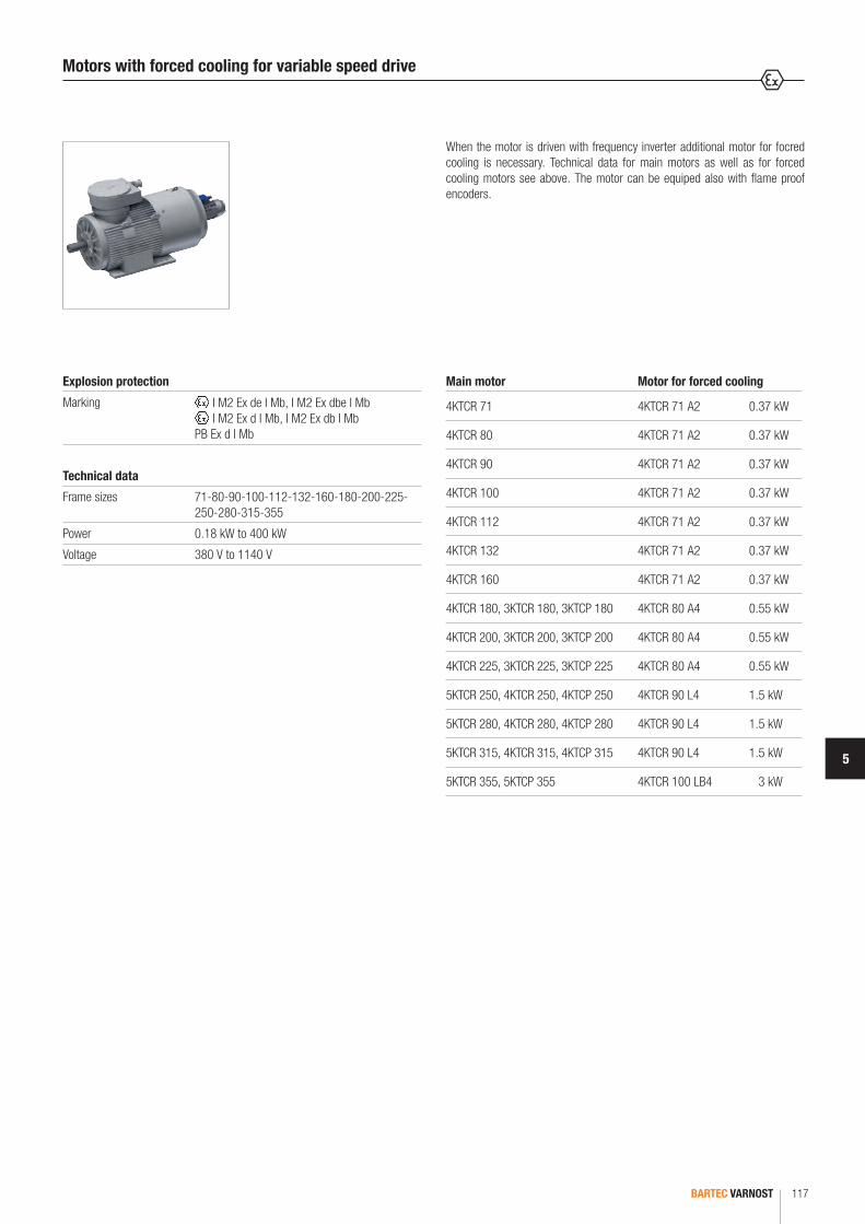
5
BARTEC VARNOST 117
Main motor Motor for forced cooling
4KTCR 71 4KTCR 71 A2 0.37 kW
4KTCR 80 4KTCR 71 A2 0.37 kW
4KTCR 90 4KTCR 71 A2 0.37 kW
4KTCR 100 4KTCR 71 A2 0.37 kW
4KTCR 112 4KTCR 71 A2 0.37 kW
4KTCR 132 4KTCR 71 A2 0.37 kW
4KTCR 160 4KTCR 71 A2 0.37 kW
4KTCR 180, 3KTCR 180, 3KTCP 180 4KTCR 80 A4 0.55 kW
4KTCR 200, 3KTCR 200, 3KTCP 200 4KTCR 80 A4 0.55 kW
4KTCR 225, 3KTCR 225, 3KTCP 225 4KTCR 80 A4 0.55 kW
5KTCR 250, 4KTCR 250, 4KTCP 250 4KTCR 90 L4 1.5 kW
5KTCR 280, 4KTCR 280, 4KTCP 280 4KTCR 90 L4 1.5 kW
5KTCR 315, 4KTCR 315, 4KTCP 315 4KTCR 90 L4 1.5 kW
5KTCR 355, 5KTCP 355 4KTCR 100 LB4 3 kW
When the motor is driven with frequency inverter additional motor for focred cooling is necessary. Technical data for main motors as well as for forced cooling motors see above. The motor can be equiped also with flame proof encoders.
Motors with forced cooling for variable speed drive
Technical data
Frame sizes 71-80-90-100-112-132-160-180-200-225- 250-280-315-355
Power 0.18 kW to 400 kW
Voltage 380 V to 1140 V
Explosion protection
Marking I M2 Ex de I Mb, I M2 Ex dbe I Mb I M2 Ex d I Mb, I M2 Ex db I Mb
PB Ex d I Mb

BARTEC VARNOST118
For fast connection our electric motors can be equiped with flame proof restrained socket.
Motor for axial fans can have shaft on DE and NDE side. Installation into the fan can be with one or with two flanges as well as on the foot.
Motors with socket/Motors for axial fans
Technical data
Frame sizes 80-90-100-112-132-160-180-200-225-250- 280-315-355
Power 0.55 kW to 400 kW
Voltage 380 V to 1140 V
Flameproof restrained socket
250 A or 350 A; 1300 V
Technical data
Frame sizes 80-90-100-112-132-160-180-200-225-250- 280-315-355
Power 0.55 kW to 400 kW
Voltage 380 V to 1140 V
With extention of connection box
Lenght of extention tube by demand
Explosion protection
Marking I M2 Ex de I Mb I M2 Ex d I Mb
PB Ex d I Mb
Explosion protection
Marking I M2 Ex de I Mb I M2 Ex d I Mb
PB Ex d I Mb
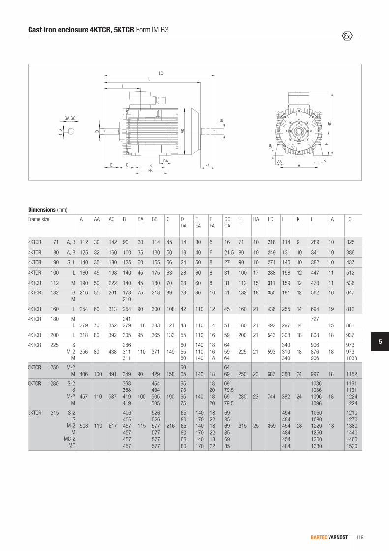
5
BARTEC VARNOST 119
HDH
DA
ACDF,FA
GA,GC
I
LLC
E CBBB
BA
DA
EAAA
AK
Dimensions (mm)
Frame size A AA AC B BA BB C D DA
EEA
F FA
GC GA
H HA HD I K L LA LC
4KTCR 71 A, B 112 30 142 90 30 114 45 14 30 5 16 71 10 218 114 9 289 10 325
4KTCR 80 A, B 125 32 160 100 35 130 50 19 40 6 21.5 80 10 249 131 10 341 10 386
4KTCR 90 S, L 140 35 180 125 60 155 56 24 50 8 27 90 10 271 140 10 382 10 437
4KTCR 100 L 160 45 198 140 45 175 63 28 60 8 31 100 17 288 158 12 447 11 512
4KTCR 112 M 190 50 222 140 45 180 70 28 60 8 31 112 15 311 159 12 470 11 536
4KTCR 132 S M
216 55 261 178 210
75 218 89 38 80 10 41 132 18 350 181 12 562 16 647
4KTCR 160 L 254 60 313 254 90 300 108 42 110 12 45 160 21 436 255 14 694 19 812
4KTCR 180 M L 279 70 352
241 279 118 333 121 48 110 14 51 180 21 492 297 14
727 15 881
4KTCR 200 L 318 80 392 305 95 365 133 55 110 16 59 200 21 543 308 18 808 18 937
4KTCR 225 S M-2
M356 80 438
286 311 311
110 371 14960 55 60
140 110 140
18 16 18
64 59 64
225 21 593340 310 340
18906 876 906
18973 973 1033
5KTCR 250 M-2 M 406 100 491 349 90 429 158
60 65 140 18
64 69 250 23 687 380 24 997 18 1152
5KTCR 280 S-2 S
M-2 M
457
110
537
368 368 419 419
100
454 454 505 505
190
65 75 65 75
140
18 20 18 20
69 79.5 69 79.5
280
23
744
382
24
1036 1036 1096 1096
18
1191 1191 1224 1224
5KTCR 315 S-2 S
M-2 M
MC-2 MC
508
110
617
406 406 457 457 457 457
115
526 526 577 577 577 577
216
65 80 65 80 65 80
140 170 140 170 140 170
18 22 18 22 18 22
69 85 69 85 69 85
315
25
859
454 484 454 484 454 484
28
1050 1080 1220 1250 1300 1330
18
1210 1270 1380 1440 1460 1520
Cast iron enclosure 4KTCR, 5KTCR Form IM B3

BARTEC VARNOST120
HD
ACD
F,FA
GA,GC
I
LAT
LLC
E C B
P N
BB
BA
DA
DA
4x90°
45°
H
M
EA AKAA
Dimensions (mm)
Frame size Flange AC D DA
EEA
F FA
GC GA
H HB I K L LA LC M N P S No. of fixing holes
4KTCR 71 A, B F 130-I 142 14 30 5 16 71 147 114 9 289 10 325 130 110 160 9 4
4KTCR 80 A, B F 165-I 160 19 40 6 21.5 80 169 131 10 341 10 386 165 130 200 12 4
4KTCR 90 S, L F 165-I 180 24 50 8 27 90 181 140 10 382 10 437 165 130 200 12 4
4KTCR 100 L F 215-I 198 28 60 8 31 100 188 158 12 447 11 512 215 180 250 14 4
4KTCR 112 M F 215-I 222 28 60 8 31 112 199 159 12 470 11 536 215 180 250 14 4
4KTCR 132 S, M F 265-I 261 38 80 10 41 132 218 181 12 562 16 647 265 230 300 14 4
4KTCR 160 M, L F 300-I 313 42 110 12 45 160 276 255 14 694 19 812 300 250 350 18 4
4KTCR 180 M L
F 300-I F 300-I 352 48 110 14 51 180 312 297 14
727 15
841 881 300 250 350 18 4
4KTCR 200 L F 350-I 392 55 110 16 59 200 343 308 18 808 18 937 350 300 400 18 4
4KTCR 225 S M-2
M
F 400-I F 400-I F 400-I
43860 55 60
140 110 140
18 16 18
64 59 64
225 368340 310 340
18906 876 906
18973 973 1033
400 350 450 18 8
5KTCR 250 M-2 M
F 500-I F 500-I 491
60 65 140 18
64 69 250 437 380 24 997 18 1152 500 450 550 19 8
5KTCR 280 S-2 S
M-2 M
F 500-I F 500-I F 500-I F 500-I
537
65 75 65 75
140
18 20 18 20
69 79.5 69 79.5
280
464
382
24
1036 1036 1096 1096
18
1191 1191 1224 1224
500
450
550
19
8
5KTCR 315 S-2 S
M-2 M
MC-2 MC
F 600-I F 600-I F 600-I F 600-I F 600-I F 600-I
617
65 80 65 80 65 80
140 170 140 170 140 170
18 22 18 22 18 22
69 85 69 85 69 85
315
544
454 484 454 484 454 484
28
1050 1080 1220 1250 1300 1330
18
1210 1270 1380 1440 1460 1520
600
550
660
24
8
Cast iron enclosure 4KTCR, 5KTCR Form IM B5 (V1)

5
BARTEC VARNOST 121
HD
ACD
F,FA
GA,GC
I
LAT
LLC
E C B
P N
BB
BA
DA
DA
4x90°
45°
H
M
EA AKAA
Dimensions (mm)
Frame size Flange A AA AB AC B BA BB C D DA
EEA
F FA
GC GA
H HA HD I K L LA LC M N P S No. of fixing holes
4KTCR 71 A, B F 130-I 112 30 140 142 90 30 114 45 14 30 5 16 71 10 218 114 9 289 10 325 130 110 160 9 4
4KTCR 80 A, B F 165-I 125 32 160 160 100 35 130 50 19 40 6 21.5 80 10 249 131 10 341 10 386 165 130 200 12 4
4KTCR 90 S, L F 165-I 140 35 180 180 125 60 155 56 24 50 8 27 90 10 271 140 10 382 10 437 165 130 200 12 4
4KTCR 100 L F 215-I 160 45 205 198 140 45 175 63 28 60 8 31 100 17 288 158 12 447 11 512 215 180 250 14 4
4KTCR 112 M F 215-I 190 50 235 222 140 45 180 70 28 60 8 31 112 15 311 159 12 470 11 536 215 180 250 14 4
4KTCR 132 S, M F 265-I 216 55 266 261 178 75 218 89 38 80 10 41 132 18 350 181 12 562 16 647 265 230 300 14 4
4KTCR 160 M, L F 300-I 254 60 312 313 254 90 300 108 42 110 12 45 160 21 436 255 14 694 19 812 300 250 350 18 4
4KTCR 180 M L
F 300-I F 300-I 279 70 348 352
241 279 118
333 121 48 110 14 51 180 21 492 297 14
727 15
841 881 300 250 350 18 4
4KTCR 200 L F 350-I 318 80 398 392 305 95 365 133 55 110 16 59 200 21 543 308 18 808 18 937 350 300 400 18 4
4KTCR 225 S M-2 M
F 400-I F 400-I F 400-I
356 80 436 438286 311 311
110376 371 371
14960 55 60
140 110 140
18 16 18
64 59 64
225 21 593340 310 340
18906 876 906
18976 973 1033
400 350 450 18 8
5KTCR 250 M-2 M
F 500-I F 500-I 406 100 506 491 349 90 429 158
60 65 140 18
64 69 250 23 687 380 24 997 18 1152 500 450 550 19 8
5KTCR 280 S-2 S M-2 M
F 500-I F 500-I F 500-I F 500-I
457
110
557
537
368 368 419 419
100
454 454 505 505
190
65 75 65 75
140
18 20 18 20
69 79.5 69 79.5
280
23
744
382
24
1036 1036 1096 1096
18
1191 1191 1224 1224
500
450
550
19
8
5KTCR 315 S-2 S M-2 M MC-2 MC
F 600-I F 600-I F 600-I F 600-I F 600-I F 600-I
508
110
628
617
406 406 457 457 457 457
115
526 526 577 577 577 577
216
65 80 65 80 65 80
140 170 140 170 140 170
18 22 18 22 18 22
69 85 69 85 69 85
315
25
859
454 484 454 484 454 484
28
1050 1080 1220 1250 1300 1330
18
1210 1270 1380 1440 1460 1520
600
550
660
24
8
Cast iron enclosure 4KTCR, 5KTCR Form IM B5/B5

BARTEC VARNOST122
HD
ACD
F,FA
GA,GC
IL
LC
E
C BBBB
BA
EA
DA
H
HA
AAA
K
AB
Dimensions (mm)
Frame size A AA AC B BA BB C D DA
EEA
F FA
GC GA
H HA HD I K L LA LC
3KTCR 180 M L 279 70 352
241 279
80295 333
121 48 110 14 51 180 21 492 299 14721 761
15841 881
3KTCR 200 L 318 80 392 305 90 395 133 55 110 16 59 200 21 543 310 18 817 18 937
3KTCR 225 S M-2
M356 80 438
286 311 311
90346 371 371
14960 55 60
140 110 140
18 16 18
64 59 64
225 21 593341 311 341
18823 853 883
18973 973 1033
4KTCR 250 M-2 M 406 100 491
34990 429 158
60 65
140 1864 69
250 23 687 380 24 997 18 1152
4KTCR 280 S-2 S
M-2 M
457 110 537
368 368 419 419
100
454 454 505 505
190
65 75 65 75
140
18 20 18 20
69 79.5 69 79.5
280 23 744 382 24
1036 1036 1096 1096
18
1191 1191 1224 1224
4KTCR 315 S-2 S
M-2 M
MC-2 MC MD
508 508 508 508 508 508 503
110 617
406 406 457 457 457 457 457
115
526 526 577 577 577 577 577
216
65 80 65 80 65 80 80
140 170 140 170 140 170 170
18 22 18 22 18 22 22
69 85 69 85 69 85 85
315 25
859 859 859 859 859 859 864
454 484 454 484 454 484 484
28
1050 1080 1220 1250 1300 1330 1430
18
1210 1270 1380 1440 1460 1520 --
5KTCR 355 SA-2 SA
SB-2 SB
LA-2 LA
LB-2 LB M
610 130 698
500 500 560 560 630 630 630 630 630
210
734 734 734 734 804 804 804 804 804
244
75 100 75 100 75 100 75 100 100
140 210 140 210 140 210 140 210 210
20 28 20 28 20 28 20 28 28
79.5 106 79.5 106 79.5 106 79.5 106 106
355 35 981
511 581 511 581 511 581 511 581 581
28
1587 1657 1587 1657 1587 1657 1587 1657 1657
25
1737 1877 1737 1877 1737 1877 1737 1877 1877
Welded enclosure 3KTCR, 4KTCR, 5KTCR Form IM B3
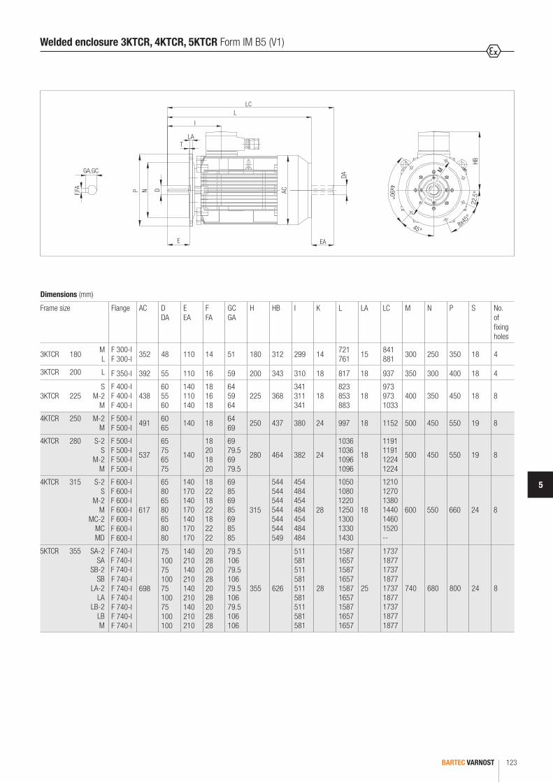
5
BARTEC VARNOST 123
HB
ACDF,FA
GA,GC
I
LAT
LLC
E
P N
DA
4x90°
8x45°
22.5
°
45°
M
EA
Dimensions (mm)
Frame size Flange AC D DA
EEA
F FA
GC GA
H HB I K L LA LC M N P S No. of fixing holes
3KTCR 180 M L
F 300-I F 300-I
352 48 110 14 51 180 312 299 14 721 761
15 841 881
300 250 350 18 4
3KTCR 200 L F 350-I 392 55 110 16 59 200 343 310 18 817 18 937 350 300 400 18 4
3KTCR 225S
M-2 M
F 400-I F 400-I F 400-I
43860 55 60
140 110 140
18 16 18
64 59 64
225 368341 311 341
18823 853 883
18973 973 1033
400 350 450 18 8
4KTCR 250 M-2 M
F 500-I F 500-I
491 60 65
140 18 64 69
250 437 380 24 997 18 1152 500 450 550 19 8
4KTCR 280 S-2 S
M-2 M
F 500-I F 500-I F 500-I F 500-I
537
65 75 65 75
140
18 20 18 20
69 79.5 69 79.5
280 464 382 24
1036 1036 1096 1096
18
1191 1191 1224 1224
500 450 550 19 8
4KTCR 315 S-2 S
M-2 M
MC-2 MC MD
F 600-I F 600-I F 600-I F 600-I F 600-I F 600-I F 600-I
617
65 80 65 80 65 80 80
140 170 140 170 140 170 170
18 22 18 22 18 22 22
69 85 69 85 69 85 85
315
544 544 544 544 544 544 549
454 484 454 484 454 484 484
28
1050 1080 1220 1250 1300 1330 1430
18
1210 1270 1380 1440 1460 1520 --
600 550 660 24 8
5KTCR 355 SA-2 SA
SB-2 SB
LA-2 LA
LB-2 LB M
F 740-I F 740-I F 740-I F 740-I F 740-I F 740-I F 740-I F 740-I F 740-I
698
75 100 75 100 75 100 75 100 100
140 210 140 210 140 210 140 210 210
20 28 20 28 20 28 20 28 28
79.5 106 79.5 106 79.5 106 79.5 106 106
355 626
511 581 511 581 511 581 511 581 581
28
1587 1657 1587 1657 1587 1657 1587 1657 1657
25
1737 1877 1737 1877 1737 1877 1737 1877 1877
740 680 800 24 8
Welded enclosure 3KTCR, 4KTCR, 5KTCR Form IM B5 (V1)
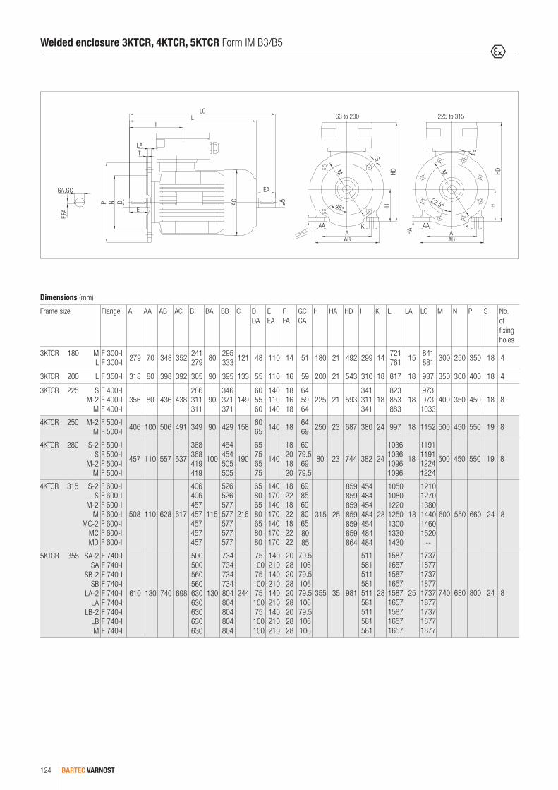
BARTEC VARNOST124
63 to 200 225 to 315
HD HD
ACDNP
F,FA
GA,GC
LA
IL
LC
T
E
EA
DA H
HA
AAA
K
AB
AAA
K
AB
SS
M M
45°22.5°
Welded enclosure 3KTCR, 4KTCR, 5KTCR Form IM B3/B5
Dimensions (mm)
Frame size Flange A AA AB AC B BA BB C D DA
EEA
F FA
GC GA
H HA HD I K L LA LC M N P S No. of fixing holes
3KTCR 180 M L
F 300-I F 300-I 279 70 348 352 241
279 80 295 333 121 48 110 14 51 180 21 492 299 14 721
761 15 841 881 300 250 350 18 4
3KTCR 200 L F 350-I 318 80 398 392 305 90 395 133 55 110 16 59 200 21 543 310 18 817 18 937 350 300 400 18 4
3KTCR 225 S M-2
M
F 400-I F 400-I F 400-I
356 80 436 438286 311 311
90346 371 371
14960 55 60
140 110 140
18 16 18
64 59 64
225 21 593341 311 341
18823 853 883
18973 973
1033400 350 450 18 8
4KTCR 250 M-2 M
F 500-I F 500-I 406 100 506 491 349 90 429 158 60
65 140 18 64 69 250 23 687 380 24 997 18 1152 500 450 550 19 8
4KTCR 280 S-2 S
M-2 M
F 500-I F 500-I F 500-I F 500-I
457 110 557 537
368 368 419 419
100
454 454 505 505
190
65 75 65 75
140
18 20 18 20
69 79.5 69
79.5
80 23 744 382 24
1036 1036 1096 1096
18
1191 1191 1224 1224
500 450 550 19 8
4KTCR 315 S-2 S
M-2 M
MC-2 MC MD
F 600-I F 600-I F 600-I F 600-I F 600-I F 600-I F 600-I
508 110 628 617
406 406 457 457 457 457 457
115
526 526 577 577 577 577 577
216
65 80 65 80 65 80 80
140 170 140 170 140 170 170
18 22 18 22 18 22 22
69 85 69 80 65 80 85
315 25
859 859 859 859 859 859 864
454 484 454 484 454 484 484
28
1050 1080 1220 1250 1300 1330 1430
18
1210 1270 1380 1440 1460 1520
--
600 550 660 24 8
5KTCR 355 SA-2 SA
SB-2 SB
LA-2 LA
LB-2 LB M
F 740-I F 740-I F 740-I F 740-I F 740-I F 740-I F 740-I F 740-I F 740-I
610 130 740 698
500 500 560 560 630 630 630 630 630
130
734 734 734 734 804 804 804 804 804
244
75 100 75
100 75
100 75
100 100
140 210 140 210 140 210 140 210 210
20 28 20 28 20 28 20 28 28
79.5 106 79.5 106 79.5 106 79.5 106 106
355 35 981
511 581 511 581 511 581 511 581 581
28
1587 1657 1587 1657 1587 1657 1587 1657 1657
25
1737 1877 1737 1877 1737 1877 1737 1877 1877
740 680 800 24 8
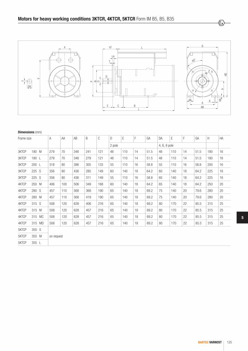
5
BARTEC VARNOST 125
HDH
HA
DNP
V
F
GA
X L Gq1
E C14
B
T
LA
L
AAA
M
45°
AB
K
Motors for heavy working conditions 3KTCR, 4KTCR, 5KTCR Form IM B5, B5, B35
Dimensions (mm)
Frame size A AA AB B C D E F GA DA E F GA H HA
2 pole 4, 6, 8 pole
3KTCP 180 M 279 70 348 241 121 48 110 14 51.5 48 110 14 51.5 180 16
3KTCP 180 L 279 70 348 279 121 48 110 14 51.5 48 110 14 51.5 180 16
3KTCP 200 L 318 80 398 305 133 55 110 16 58.8 55 110 16 58.8 200 16
3KTCP 225 S 356 80 436 285 149 60 140 18 64.2 60 140 18 64.2 225 16
3KTCP 225 S 356 80 436 311 149 55 110 16 58.8 60 140 18 64.2 225 16
4KTCP 250 M 406 100 506 349 168 60 140 18 64.2 65 140 18 64.2 250 20
4KTCP 280 S 457 110 568 368 190 65 140 18 69.2 75 140 20 79.6 280 20
4KTCP 280 M 457 110 568 419 190 65 140 18 69.2 75 140 20 79.6 280 20
4KTCP 315 S 508 120 628 406 216 65 140 18 69.2 80 170 22 85.5 315 25
4KTCP 315 M 508 120 628 457 216 65 140 18 69.2 80 170 22 85.5 315 25
4KTCP 315 MC 508 120 628 457 216 65 140 18 69.2 80 170 22 85.5 315 25
4KTCP 315 MD 508 120 628 457 216 65 140 18 69.2 80 170 22 85.5 315 25
5KTCP 355 S
on request5KTCP 355 M
5KTCP 355 L
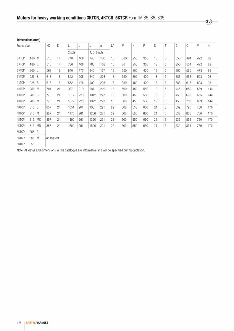
BARTEC VARNOST126
Motors for heavy working conditions 3KTCR, 4KTCR, 5KTCR Form IM B5, B5, B35
Dimensions (mm)
Frame size HD K L q L q LA M N P S T G O V X
2 pole 4, 6, 8 pole
3KTCP 180 M 510 14 740 168 740 168 15 300 250 350 18 5 350 494 422 82
3KTCP 180 L 510 14 780 168 780 168 15 30 250 350 18 5 350 534 422 82
3KTCP 200 L 563 18 840 177 840 177 18 350 300 400 18 5 385 585 473 98
3KTCP 225 S 613 18 842 208 842 208 18 350 300 400 18 5 386 556 523 98
3KTCP 225 S 613 18 872 178 902 208 18 350 450 400 18 5 386 616 523 98
4KTCP 250 M 701 24 987 219 987 219 18 500 450 550 19 5 446 660 589 144
4KTCP 280 S 770 24 1012 223 1012 223 18 500 450 550 19 5 456 690 655 144
4KTCP 280 M 770 24 1072 223 1072 223 18 500 450 550 19 5 456 750 659 144
4KTCP 315 S 857 24 1051 261 1081 291 22 600 550 660 24 6 532 795 760 170
4KTCP 315 M 857 24 1176 261 1206 291 22 600 550 660 24 6 532 855 760 170
4KTCP 315 MC 857 24 1390 261 1390 291 22 600 550 660 24 6 532 855 760 170
4KTCP 315 MD 857 24 1600 261 1600 291 22 600 550 660 24 6 532 855 760 170
5KTCP 355 S
on request5KTCP 355 M
5KTCP 355 L
Note: All datas and dimensions in this catalogue are informative and will be specified during quotation.

5
BARTEC VARNOST 127
Special applications/options
Frame size 71 80 90 100 112 132 160 180 200 225 250 280 315 355
Special voltage up to 1140 V
Special frequency
Frequency inverter drive
Special power op op op op op op op op op op op op op op
Special shaft end op op op op op op op op op op op op op op
Free shaft end on NDS-end of motor
Special flange op op op op op op op op op op op op op op
Flange made in R acc. to DIN 42955
Additional greasing
Fixed bearing on AS
2RS bearings
Labyrinth seal
Oil seal
Protection IP 56
Protection IP 65 op op op op op op op op op op op op op op
Protection IP 66 op op op op op op op op op op op op op op
Protection cover
Vibrations within R or S limits
SPM placing op op op op op op op op
Special data plate
Terminal box with Ex d cable glands op op op op op op op op op op op op op op
Terminal box with socket op op op op op op op op op op op op op op
Thermal protection of winding
Heating of winding against condensation
Heating of winding at temp. lower -20 °C
Insulation class H
Special colour
= on requestop = option
Ordering data
rating in kW
voltage and frequency
r.p.m.
type of motor arrangement (form IM ..)
mechanical requirements
special requirements (i.e. H-class thermal insulation, two-shaft, radial bearing seals…).

BARTEC Catalogue Electric Motors Edition 2017 Printed in Germany
Reservation
Technical data subject to change without notice. No claims for damages arising from alterations, errors or misprints shall be allowed. Attention is drawn to the applicable standards and regulations on safety components and systems together with the relevant operating and installation instructions.


BARTEC GmbH
Max-Eyth-Str. 16 97980 Bad Mergentheim Germany
Phone: +49 7931 597 0 Fax: +49 7931 597 119 [email protected] www.bartec.de
ELECTRIC MOTORS
BARTEC VARNOST d.o.o.
Cesta 9, avgusta 59 1410 Zagorje ob Savi Slovenia
Phone: +386 59 221 471 Fax: +386 59 221 470 [email protected] www.bartec-varnost.si
ELEC
TRIC
MOT
ORS
201
7
UK-D
-BM
E131
0201
7-10
/201
7-M
arke
ting
& Co
mm
unic
atio
ns-4
1566
9


![inDEx [ ] · PDF fileCEi En50347 iEC 60072-1 iEC 60072-2 The coupling dimensions are in compliance with the following standards: unEL 13113-71 for the B3 mounting and for other frame](https://static.fdocuments.us/doc/165x107/5a9f52a87f8b9a71178c9dee/index-en50347-iec-60072-1-iec-60072-2-the-coupling-dimensions-are-in-compliance.jpg)