Electric Motor and Dry Clutch Control in Launch Manoeuvres ...
17
Exchanges: The Interdisciplinary Research Journal 65 Pisaturo & Senatore. Exchanges 2019 7(1), pp. 65-81 Electric Motor and Dry Clutch Control in Launch Manoeuvres of Mild-Hybrid Vehicles Based on AMT/DCT Transmissions Mario Pisaturo * and Adolfo Senatore Department of Industrial Engineering, University of Salerno, Italy *Correspondence: [email protected] Abstract Mild-Hybrid Electric Vehicles (mild-HEVs) earned market share over the last years an as effective roadmap to limit air pollution in big cities. In addition to this role, hybrid propulsion can be used to avoid dry clutch overheating in mild-HEVs equipped with automated manual transmissions. Indeed, high thermal level could result in serious damaging of dry clutch linings with very fast decay of expected lifespan affecting vehicle reliability. This paper shows results of vehicle launch simulations to highlight how the propulsion due to electric motor can effectively reduce clutch thermal stress during the slipping phase. Keywords: Hybrid electric vehicle; dry clutch; engagement control Introduction In the last decades, Hybrid Electric Vehicles (HEVs) and Electric Vehicles (EVs) are gaining significant share of the automobile market. Their success is mainly due to higher fuel efficiency than conventional vehicles which results also in a reduction of pollutant emissions. By analysing the driveline structure, in parallel HEVs both the internal combustion engine (ICE) and electric motor (EM) can propel, separately or at the same time, the vehicle wheels. Series HEVs differ from parallel HEVs in the role of ICE as energy from combustion engine is converted into electric energy to charge the battery pack or to propel the wheels (Chan, 2007; Oh et al., 2007; Pisu & Rizzoni, 2007). The importance of moving toward sustainable mobility is strongly linked to the need to reduce air pollution and the greenhouse effect, especially in big cities. To this aim, many studies have been proposed to improve the efficiency of hybrid vehicles. Peer review: This article has been subject to a double-blind peer review process Copyright notice: This article is issued under the terms of the Creative Commons Attribution License, which permits use and redistribution of the work provided that the original author and source are credited. You must give appropriate credit (author attribution), provide a link to the license, and indicate if changes were made. You may do so in any reasonable manner, but not in any way that suggests the licensor endorses you or your use. You may not apply legal terms or technological measures that legally restrict others from doing anything the license permits. https://creativecommons .org/licenses/by/4.0/
Transcript of Electric Motor and Dry Clutch Control in Launch Manoeuvres ...

Exchanges: The Interdisciplinary Research Journal
65 Pisaturo & Senatore. Exchanges 2019 7(1), pp. 65-81
Electric Motor and Dry Clutch Control in
Launch Manoeuvres of Mild-Hybrid
Vehicles Based on AMT/DCT Transmissions
Mario Pisaturo* and Adolfo Senatore
Department of Industrial Engineering, University of Salerno, Italy
*Correspondence: [email protected]
Abstract
Mild-Hybrid Electric Vehicles (mild-HEVs) earned market share over the last
years an as effective roadmap to limit air pollution in big cities. In addition
to this role, hybrid propulsion can be used to avoid dry clutch overheating
in mild-HEVs equipped with automated manual transmissions. Indeed,
high thermal level could result in serious damaging of dry clutch linings
with very fast decay of expected lifespan affecting vehicle reliability. This
paper shows results of vehicle launch simulations to highlight how the
propulsion due to electric motor can effectively reduce clutch thermal
stress during the slipping phase.
Keywords: Hybrid electric vehicle; dry clutch; engagement control
Introduction
In the last decades, Hybrid Electric Vehicles (HEVs) and Electric Vehicles
(EVs) are gaining significant share of the automobile market. Their success
is mainly due to higher fuel efficiency than conventional vehicles which
results also in a reduction of pollutant emissions.
By analysing the driveline structure, in parallel HEVs both the internal
combustion engine (ICE) and electric motor (EM) can propel, separately or
at the same time, the vehicle wheels. Series HEVs differ from parallel HEVs
in the role of ICE as energy from combustion engine is converted into
electric energy to charge the battery pack or to propel the wheels (Chan,
2007; Oh et al., 2007; Pisu & Rizzoni, 2007).
The importance of moving toward sustainable mobility is strongly linked
to the need to reduce air pollution and the greenhouse effect, especially
in big cities. To this aim, many studies have been proposed to improve the
efficiency of hybrid vehicles.
Peer review: This article
has been subject to a
double-blind peer review
process
Copyright notice: This
article is issued under the
terms of the Creative
Commons Attribution
License, which permits
use and redistribution of
the work provided that
the original author and
source are credited.
You must give
appropriate credit
(author attribution),
provide a link to the
license, and indicate if
changes were made. You
may do so in any
reasonable manner, but
not in any way that
suggests the licensor
endorses you or your use.
You may not apply legal
terms or technological
measures that legally
restrict others from doing
anything the license
permits.
https://creativecommons
.org/licenses/by/4.0/

Exchanges: The Interdisciplinary Research Journal
66 Pisaturo & Senatore. Exchanges 2019 7(1), pp. 65-81
In (Wang et al., 2015), dynamic programming global optimization
algorithm is applied in HEV to search optimal solution in an assigned speed
cycle that minimize the fuel consumption keeping the balance of battery
state of charge (SOC). Moreover, in (Tribioli et al., 2014) a real-time energy
management strategy for plugin HEVs based on optimal control theory is
proposed.
In (Ye et al., 2013), a comprehensive control scheme, including energy
management and coordinated control of parallel hybrid electric bus with
automated manual transmission (AMT) based on dry clutch is presented.
Instead, in (Vagg et al., 2016) a stochastic dynamic programming (SDP) is
applied to optimal control of HEV.
The electric motor (EM) can even play a crucial role to reduce the thermal
stress in dry clutch automated manual transmission (AMT) and dual clutch
transmission (DCT) during the slipping phase by avoiding critical values
(Pisaturo & Senatore, 2017; Pisaturo, Senatore & D’Agostino, 2017).
Indeed, the most important problem with dry clutch systems like AMT and
DCT is the overheating due to repeated shifting (Pica et al., 2016; Pisaturo
& Senatore, 2016) that results in poor quality engagements or even
permanent damage of clutch frictional materials or facings. Thus, the
accuracy of clutch temperature estimation deeply affects the control unit
decisions. This paper is an extended version of (Pisaturo & Senatore, 2017)
but conversely from it, in this paper a more complex thermal model has
been implemented in the transmission control unit (TCU) to activate the
EM and reduce thermal stress on clutch components. Indeed, the
advantage to have a complex thermal model is to better predict the
transmitted clutch torque and consequently the improvement of the
passenger comfort together to the extension of clutch life. Furthermore,
the actuators’ delay have been considered in the Model Predictive Control
(MPC) design in the choice of both control and prediction to improve
control performances. Particularly, critical launch manoeuvres with high
initial clutch material temperature are taken into account. The results
highlight how the activation of EM reduces the thermal power generated
during the engagement manoeuvre by inhibiting clutch damage.
Parallel HEV Driveline
Driveline model
This section describes the driveline model used for simulating the parallel
HEV longitudinal dynamics, where T indicates the torques, J the inertias
and b the damping coefficients. Moreover, the subscripts e, f, c, g, d, m, w
indicate engine, flywheel, clutch disc, gearbox, differential, electric motor
and wheels, respectively. The scheme of the analysed driveline under the

Exchanges: The Interdisciplinary Research Journal
67 Pisaturo & Senatore. Exchanges 2019 7(1), pp. 65-81
hypothesis of rigidity of all the shafts is reported in Figure 1 and the related
equations are:
ef e e e e fcJ T b T = − − (1)
( ) ( )( )2 2
1 2 1 2v w d fc d m g d m d w wJ r r T sr r T b r r sb r r T = + − + − (2)
where r1, r2 and rd, are the gear ratios on the engine side, electric motor
side and differential respectively. Moreover, s is a parameter used to
switch between the HEV mode (s = 1) and pure ICE mode (s = 0). In
addition, the following positions hold:
( ) ( )( ) ( )( )
( )
2 22
2 1 1 3 2
2
1sin( ) cos( )
2
ef e f
v w d g d g c d g m d
w w x w brake
J J J
J J J J r J J r r J sJ r r
T mgR f AC v R T
= +
= + + + + + +
= + + +
(3)
where, m is the vehicle mass, Rw is the wheel radius, is the road slope, f
is the rolling resistance coefficient, aria ρ is the air density, A is the vehicle
frontal area, Cx is the air drag coefficient, v the vehicle speed and Tbrake is
the braking torque.
Figure 1 Driveline model.
The equation related to the “locked-up” model can be easily achieved from
eqs. (1) and (2) by taking into account driveline dynamics reduced to
engine (or wheel) shaft.
Internal combustion engine model
The engine behaviour has been implemented through a static torque map
as function of engine speed (“plant” output) and accelerator pedal as well.
Particularly, the first MPC output given by the reference engine torque is
used to achieve the accelerator pedal signal by way of engine map
inversion. Moreover, the delay introduced by the so-called engine torque
build-up is modelled in all the performed simulations. Such an effect is
related to the transient response turbocharger in modern automotive and
truck diesel engines to attain steady-state conditions since optimization as

Exchanges: The Interdisciplinary Research Journal
68 Pisaturo & Senatore. Exchanges 2019 7(1), pp. 65-81
design key-factor is based on low specific consumption in stationary states
(Rakopoulos & Giakoumis, 2009).
Models for Dry Clutch and Electric Motor
Dry clutch model
In (Vasca et al., 2011), a model of frictional torque in dry clutch based AMT
gearbox is proposed. The paper underlines the role of the cushion spring
load-deflection characteristic as well as its influence on clutch torque
transmission. The model is depicted by neglecting the thermal effects.
Instead, in (D’Agostino, Senatore & Pisaturo, 2013) the Authors proposed
a more complex transmissibility model which covers thermal effects both
on cushion spring and clutch frictional response:
( , , , , ) ( , , ) ( ( ( , ), ))fc to fs cm s s cm m fc f pp to fs fsT x v p n v p R F x x =
(4)
where Tfc is the transmitted clutch torque, xto is the throwout bearing
position, θfs and θcm are the cushion spring and clutch material
temperature respectively. vs = Rm ωsl is the linear sliding speed, Rm is the
mean radius, ωsl = |e-c| is the difference between the engine and clutch
angular speeds, p is the contact pressure, n is the number of friction
surfaces, μ is the friction coefficient, Ffc is the clamping force, δf is the
cushion spring deflection and xpp is the pressure plate position.
The clutch torque model is coupled to the temperature rise equation
through the cushion spring load-deflection characteristic and frictional
material response as well. The clutch actuator dynamics is given by
discrete-time model with unitary gain first-order transfer and 0.1 s time
constant. Thus, the reference clutch torque, i.e. the second output of the
controller is inverted by a simplified clutch model to provide as output the
reference throwout bearing position (“position controlled clutch”). The
latter signal as input of the clutch actuator allows the calculation of the
actual clutch torque in a detailed clutch torque map (n-D look-up table).
By considering the clutch transmissibility model described in equation (4),
it is clear that an estimation of both clutch facing and cushion spring
temperature is necessary. For this reason, a lumped thermal model has
been implemented to take the temperature rise into account during the
slipping phase. The model is inspired to the thermal model proposed in
(Pica et al., 2016) whereas in the present paper the cushion spring
response to the temperature change is modelled in addition to frictional
material response. The main hypothesis is that the whole mechanical work
is converted into heat by friction phenomena and that it is equally
distributed onto the frictional surfaces. Moreover, when clutch is open,
i.e. = 0, only convective losses take place whereas when clutch is in the
slipping phase, i.e. = 1, only conductive phenomena occur and

Exchanges: The Interdisciplinary Research Journal
69 Pisaturo & Senatore. Exchanges 2019 7(1), pp. 65-81
convective losses are negligible on cushion spring and clutch material. On
the contrary, the body convective losses cannot be neglected when the
clutch is closed. For this reason, the term (2 - ) accounts for about
doubled clutch surface active to convective heat exchange when clutch is
open. Thus, the thermal dynamics of clutch material θcm, body θb and
cushion spring θfs is provided by first order differential equations:
( ) ( )( )
( ) ( )( ) ( )
( ) ( )( )
1 2 3
4 5 6 7
8 9
22
12
2 1
fc sl
b cm b b h
fc sl
cm cm b cm h cm fs
fs cm fs fs h
T
T
= − − − − +
= − − − − − − − +
= − − − − −
(5)
where θh is the ambient temperature assumed constant and αi are the
thermal parameters which need to be identified.
Due to the difficulties and costs to measure both the interface
temperature and cushion spring temperature in a real system, results from
Finite Element Analysis (FEA) (Pisaturo & Senatore, 2016) have been used
to estimate the thermal parameters αi. Particularly, the same thermal
power used as energy source in FEA model has been fed as input of
thermal model described above.
Furthermore, both clutch material and cushion spring reference
temperatures used for parameter estimation have been calculated at
mean radius. For the sake of brevity, the readers can find details on
thermal parameters, on thermal power input and how the latter has been
calculated for the three analysed launch manoeuvres in (Pisaturo &
Senatore, 2016).
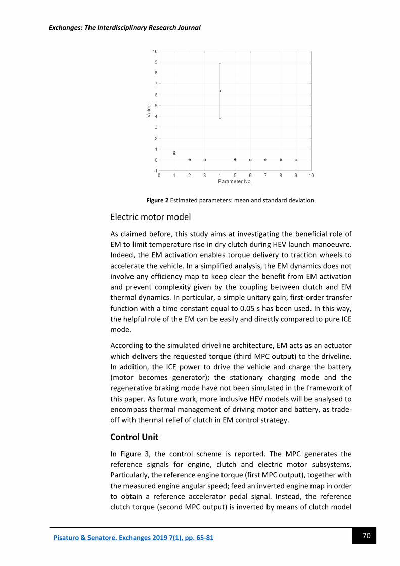
Finally, In Figure 4 the mean and standard deviation of each parameter has
been plotted. It is worth noting that, the main influencing phenomenon is
the thermal conduction between clutch material and pressure plate
(flywheel). Indeed, the two parameters 1 and 4 have the greatest values.
Particularly, the parameter 4 features both the highest value and the
highest uncertainty.
Exchanges: The Interdisciplinary Research Journal
70 Pisaturo & Senatore. Exchanges 2019 7(1), pp. 65-81
Figure 2 Estimated parameters: mean and standard deviation.
Electric motor model
As claimed before, this study aims at investigating the beneficial role of
EM to limit temperature rise in dry clutch during HEV launch manoeuvre.
Indeed, the EM activation enables torque delivery to traction wheels to
accelerate the vehicle. In a simplified analysis, the EM dynamics does not
involve any efficiency map to keep clear the benefit from EM activation
and prevent complexity given by the coupling between clutch and EM
thermal dynamics. In particular, a simple unitary gain, first-order transfer
function with a time constant equal to 0.05 s has been used. In this way,
the helpful role of the EM can be easily and directly compared to pure ICE
mode.
According to the simulated driveline architecture, EM acts as an actuator
which delivers the requested torque (third MPC output) to the driveline.
In addition, the ICE power to drive the vehicle and charge the battery
(motor becomes generator); the stationary charging mode and the
regenerative braking mode have not been simulated in the framework of
this paper. As future work, more inclusive HEV models will be analysed to
encompass thermal management of driving motor and battery, as trade-
off with thermal relief of clutch in EM control strategy.
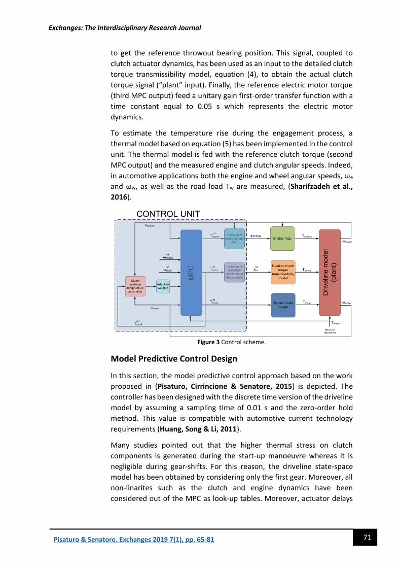
Control Unit
In Figure 3, the control scheme is reported. The MPC generates the
reference signals for engine, clutch and electric motor subsystems.
Particularly, the reference engine torque (first MPC output), together with
the measured engine angular speed; feed an inverted engine map in order
to obtain a reference accelerator pedal signal. Instead, the reference
clutch torque (second MPC output) is inverted by means of clutch model
Exchanges: The Interdisciplinary Research Journal
71 Pisaturo & Senatore. Exchanges 2019 7(1), pp. 65-81
to get the reference throwout bearing position. This signal, coupled to
clutch actuator dynamics, has been used as an input to the detailed clutch
torque transmissibility model, equation (4), to obtain the actual clutch
torque signal (“plant” input). Finally, the reference electric motor torque
(third MPC output) feed a unitary gain first-order transfer function with a
time constant equal to 0.05 s which represents the electric motor
dynamics.
To estimate the temperature rise during the engagement process, a
thermal model based on equation (5) has been implemented in the control
unit. The thermal model is fed with the reference clutch torque (second
MPC output) and the measured engine and clutch angular speeds. Indeed,
in automotive applications both the engine and wheel angular speeds, ωe
and ωw, as well as the road load Tw are measured, (Sharifzadeh et al.,
2016).
Figure 3 Control scheme.
Model Predictive Control Design
In this section, the model predictive control approach based on the work
proposed in (Pisaturo, Cirrincione & Senatore, 2015) is depicted. The
controller has been designed with the discrete time version of the driveline
model by assuming a sampling time of 0.01 s and the zero-order hold
method. This value is compatible with automotive current technology
requirements (Huang, Song & Li, 2011).
Many studies pointed out that the higher thermal stress on clutch
components is generated during the start-up manoeuvre whereas it is
negligible during gear-shifts. For this reason, the driveline state-space
model has been obtained by considering only the first gear. Moreover, all
non-linarites such as the clutch and engine dynamics have been
considered out of the MPC as look-up tables. Moreover, actuator delays

Exchanges: The Interdisciplinary Research Journal
72 Pisaturo & Senatore. Exchanges 2019 7(1), pp. 65-81
have been considered in the MPC design to improve controller
performances.
The state-space representation used to design the MPC is reported below:
1 ( )k k MV k k MD k
k k
+ −= + +
=
x A
y
vx B u
Cx
B
(6)
where x = [ωe ωw]T is the state vector, y = [ωe ωc]T is the output vectors
and u = [Te Tfc Tm]T is the manipulated variables vector, v = [Tw] is the
measured disturbance vector and ωe and ωw are the measured outputs of
the controller.
The state matrix is ( )
2
1
0
0
e
ef
g d
v
b
J
b r r
J
−
= −
A , the input matrix is
1 2
0 01
0
1
1
ef ef
d d
v v v
J J
r r r rs
J J J
−
= =
−
MV MDB B B and the output matrix is
1
1 0
0 dr r
=
C .
Plant constraints
Some constraints both on the “plant” input and output have been selected
to design the MPC and avoid the engine stall condition and provide
comfortable lock-up at the same time. On the “plant” input saturation
constraints have been imposed both on the torques:
82 334eT Nm− (7)
0 400fcT Nm
(8)
0 140mT Nm (9)
where -82 Nm and 334 Nm are the minimum and maximum engine torque
values obtained from the engine static map. Moreover, 0 Nm and 400 Nm
are the minimum and maximum torque values that the clutch can
transmit. The maximum value has been assumed 20 % greater than
maximum engine torque. Finally, 0 Nm and 140 Nm are the minimum and
maximum torque values that the electric motor can generate. As
introduced before, in this study only the pure electric mode has been
considered and the regenerative phase has not simulated.
Besides, to avoid the engine stall condition and guarantee comfortable
lock-up, some constraints have been adopted also on “plant” outputs, i.e.
engine and clutch angular speeds.

Exchanges: The Interdisciplinary Research Journal
73 Pisaturo & Senatore. Exchanges 2019 7(1), pp. 65-81
80 500 /e rad s (10)
0 /c rad s (11)
where 80 rad/s represents the so-called no-kill condition (Glielmo et al.,
2006), 500 rad/s is the maximum value of the engine speed before
attaining critical conditions. Also these values have been obtained from
the engine static map. Finally, 0 rad/s is the minimum clutch angular speed
imposed to avoid reverse motion. It is worth noting that it is not necessary
to impose a maximum clutch angular speed, because it is equal to the
engine angular speed during the engaged phase and it can only decrease
for passive resistance during the idle phase.
Optimization problem and tuning
The goal of the optimization problem is to minimize a cost function while
satisfying constraints at each time step. As previously explained, the
actuator delays have been considered in the MPC design. This affects the
choice of both control and prediction horizon as follows:
( )max ,c m
s
p mT
−
(12)
where p is the prediction horizon, m is the control horizon, τc and τm are
the clutch and electric motor actuator delays respectively and Ts is the
sampling time. As mentioned above, the clutch actuator delay is 0.1 s and
the sampling time is 0.01 s, thus the implemented values are p = 25, m =
1. The implemented cost function to be minimizes is:
(13)
2 2 2
, arg , , arg , ,
T TT
j j y j j j i t et i u i i t et i i u i iF = − − + + − − y r W y r u u W u u u W u
where ui is the input vector, utarget,i = [0, 0, Tm,max] is the input target vector,
ui is the input increment vector, yi is the output vector, ri is the set point
trajectory vector. Finally, the subscript i and j take into account the i-th
inputs and j-th outputs of the “plant” respectively.
According to working conditions, adjustable weights for “plant” inputs and
outputs have been implemented to trigger on the electric motor when the
estimated clutch temperature reaches the threshold value of 200 °C.
Particularly, if the clutch temperature is lower than 200 °C the input
weights are Wu = diag(0, 0, 0). On the contrary, when the clutch
temperature overcomes 200 °C the input weights are Wu = diag(0, 0, 5). In
this way, to minimize the second term of the cost function, the difference
between the input vector and the input target vector should be zero, i.e.
Tmref = Tm,max. It is worth noting that the weights of the first two inputs are
zero. This means that their difference from the target values does not

Exchanges: The Interdisciplinary Research Journal
74 Pisaturo & Senatore. Exchanges 2019 7(1), pp. 65-81
affect the cost function. Finally, constant weights have been assumed for
input increment Wu = diag(0.15, 0.10, 0.20) and output Wy = diag(1, 1).
Simulation Results
In this section, two scenarios of vehicle launch manoeuvre simulating
heavy working conditions are presented. Particularly, in the first scenario,
an initial temperature of 190 °C as a result of previous engagements is
assumed whereas an initial temperature of 210 °C in the second scenario.
Moreover, for both scenarios a road slope of 10 degree has been
considered. In such circumstances, the amount of heat produced during
the start-up manoeuvre could result in clutch material drawback.
Moreover, repeated uphill launch makeovers in crowded traffic
conditions, namely repeated clutch engagement in short time, are tangible
danger to attain high interface temperatures and consequently clutch
facings damage (Feng, Yimin and Juncheng, 2010). At this end, custom
Matlab/Simulink model which takes into account a detailed dry clutch
torque transmissibility model (i.e. by considering cushion spring thermal
expansion and temperature-pressure-sliding speed dependent friction
coefficient) has been implemented to simulate the longitudinal vehicle
dynamics.
As previously explained, the control strategy penalizes the electric motor
activation if the estimated clutch material temperature is less than 200 °C.
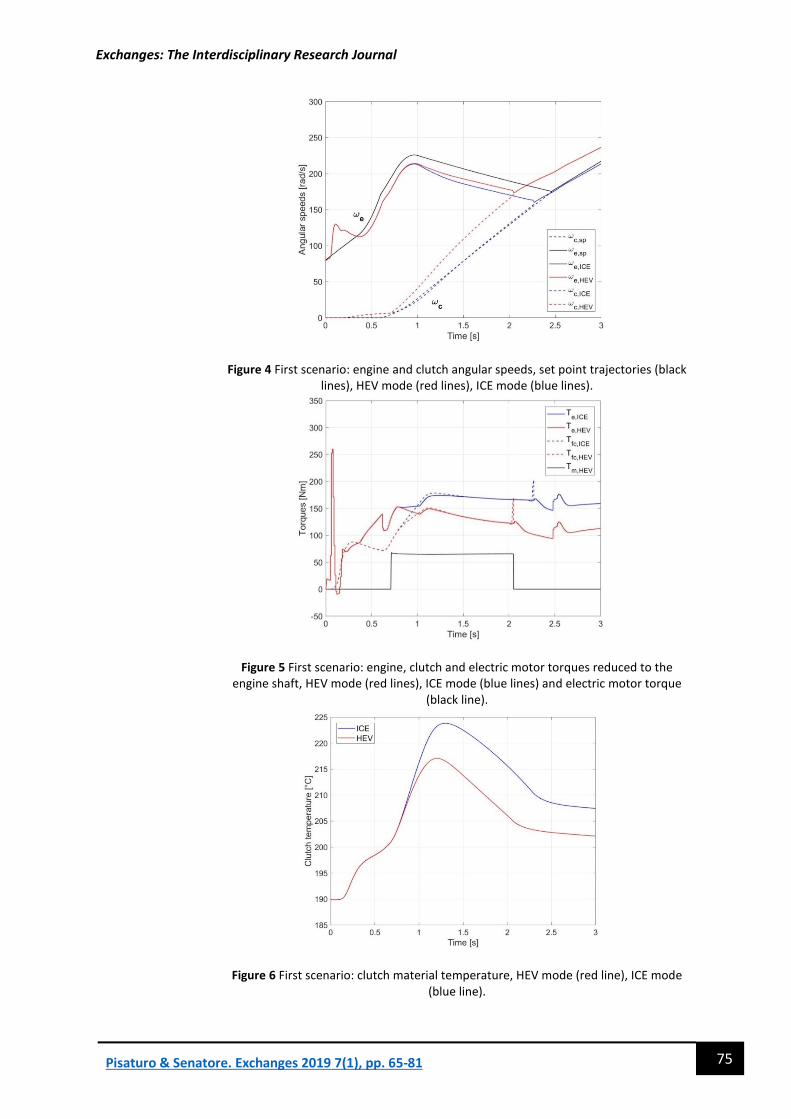
In Figures 4, 5 and 6, results of the analysed launch manoeuvre are
reported in pure ICE mode and HEV mode. With reference to the latter
case, in Figure 4 is highlighted as after about 0.7 s the clutch angular speed
slope is higher than the pure ICE mode. This is due to the electric motor
activation which delivers more torque to the traction wheels, see Figure 5.
This results in a decrease of both engine and clutch torque and
consequently in a reduction of the thermal power generated during the
slipping phase. Moreover, as shown in Figure 6, the activation
temperature threshold is reached and there is the transition from pure ICE
to hybrid propulsion, i.e. Tm > 0 (red line). Finally, in Figure 6 is shown as in
the HEV mode clutch peak temperature is about 7 °C lower than the ICE
mode.
Exchanges: The Interdisciplinary Research Journal
75 Pisaturo & Senatore. Exchanges 2019 7(1), pp. 65-81
Figure 4 First scenario: engine and clutch angular speeds, set point trajectories (black lines), HEV mode (red lines), ICE mode (blue lines).
Figure 5 First scenario: engine, clutch and electric motor torques reduced to the engine shaft, HEV mode (red lines), ICE mode (blue lines) and electric motor torque
(black line).
Figure 6 First scenario: clutch material temperature, HEV mode (red line), ICE mode (blue line).

Exchanges: The Interdisciplinary Research Journal
76 Pisaturo & Senatore. Exchanges 2019 7(1), pp. 65-81
In the second scenario, an initial clutch temperature equal to 210 °C is
selected; so, the activation temperature has already been overcome after
previous clutch operations. With the same arrangement of the figures as
for previous case, the first obvious result is the switching-on of the electric
motor (Tm > 0 in Figure 8) since the first instants, as the MPC control rapidly
triggers the electric propulsion to comply with the discussed temperature
onset. The clutch torque spikes at the end of the engagement phase,
highlighted in Figure 5 and 8, occur because the difference between the
engine and clutch angular speeds are lower than the threshold at which
the clutch is considered locked-up. Consequently, the TCU drives rapidly
the clutch actuator to its rest position. This could results into longitudinal
vibrations but by adapting the threshold it is possible to reduce them. In
our case, the aim is to reduce the clutch damage due to thermal stress thus
slightly higher vibrations are accepted.
In Figure 9, it is shown the clutch material temperature rising around 33 °C
in ICE mode, whereas the temperature rise in the same manoeuvre in HEV
mode is only 18 °C: i.e. about 45% less than the clutch temperature
increase in ICE mode.
Figure 7 Second scenario: engine and clutch angular speeds, set point trajectories
(black lines), HEV mode (red lines), ICE mode (blue lines).
Conclusions
This paper explores the benefits achievable in HEVs equipped with
automated manual transmissions in preventing dry-clutch system from
overheating problems. At this end, an investigation on the role of EM to
minimize temperature rise in dry clutch AMT/DCT during the slipping
phase is proposed. Simulations of start-up manoeuvre under hypothesis of
initial temperature of 190 °C or 210 °C and road slope of 10 degree with
and without electric propulsion aid have been carried out. The results

Exchanges: The Interdisciplinary Research Journal
77 Pisaturo & Senatore. Exchanges 2019 7(1), pp. 65-81
Figure 8 Second scenario: engine, clutch and electric motor torques reduced to the engine shaft, HEV mode (red lines), ICE mode (blue lines) and electric motor torque
(black line).
Figure 9 First scenario: clutch material temperature, HEV mode (red line), ICE mode
(blue line).
underline lower temperature rise of clutch material in HEV mode: with the
aid of EM, the reduction of clutch temperature attains 20% or even 45%,
according to the given scenarios. Under this light, the electric motor
activation remarkably prevents clutch overheating after repeated
engagements. Future analyses will embody more complex HEV model to
include also the thermal evolution of the electric motor as well as the
battery status to explore optimal trade-off between the temperatures of
such components with the required thermal relief of dry clutch system.
Exchanges: The Interdisciplinary Research Journal
78 Pisaturo & Senatore. Exchanges 2019 7(1), pp. 65-81
Table of Figures
Figure 1. Driveline model.
Figure 2. Estimated parameters: mean and standard deviation.
Figure 3. Control scheme.
Figure 4. First scenario: engine and clutch angular speeds, set point
trajectories (black lines), HEV mode (red lines), ICE mode (blue lines).
Figure 5. First scenario: engine, clutch and electric motor torques reduced
to the engine shaft, HEV mode (red lines), ICE mode (blue lines) and
electric motor torque (black line).
Figure 6. First scenario: clutch material temperature, HEV mode (red line),
ICE mode (blue line).
Figure 7. Second scenario: engine and clutch angular speeds, set point
trajectories (black lines), HEV mode (red lines), ICE mode (blue lines).
Figure 8. Second scenario: engine, clutch and electric motor torques
reduced to the engine shaft, HEV mode (red lines), ICE mode (blue lines)
and electric motor torque (black line).
Figure 9. First scenario: clutch material temperature, HEV mode (red line),
ICE mode (blue line).

Exchanges: The Interdisciplinary Research Journal
79 Pisaturo & Senatore. Exchanges 2019 7(1), pp. 65-81
Mario Pisaturo received the M.Sc. and Ph.D. degrees
in mechanical engineering from the University of
Salerno, Italy, in 2010 and 2014, respectively. He is
fellow of Department of Industrial Engineering,
University of Salerno. The main research topic is:
analysis theoretical/experimental of dry clutches for
automotive with regard to automated manual
transmissions and hybrid vehicles. He served as
reviewer for several journals on the topics of
Mechanics, Mechatronics, Tribology.
Adolfo Senatore received Ph.D. degree in Tribology
from the University of Pisa, Italy, in 2002. He has been
serving as Associate Professor at the Department of
Industrial Engineering, University of Salerno, (2014-
current). Teacher of Mechatronics (2004-) and
Mechanical Vibrations (2016-). His scientific work is
documented by more than 190 scientific papers in the
following areas: frictional modeling and model-based
control of automotive transmissions, lubrication in
internal combustion engines and journal bearings,
innovative lubricants. He visited as Guest Professor
the Department of Applied Mechanics of the
Technische Universitat Berlin under DAAD program.
References
Chan, C. C. (2007) ‘The State of the Art of Electric, Hybrid, and Fuel Cell
Vehicles’, Proceedings of the IEEE, 95(4), pp. 704–718. doi:
10.1109/JPROC.2007.892489.
D’Agostino, V., Senatore, A. and Pisaturo, M. (2013) ‘Improving the
engagement performance of automated dry clutch through the analysis
of the influence of the main parameters on the frictional map’, in 5th
World Tribology Congress. Turin.
Feng, H., Yimin, M. and Juncheng, L. (2010) ‘Study on heat fading of
phenolic resin friction material for micro-automobile clutch’, 2010
International Conference on Measuring Technology and Mechatronics
Automation, ICMTMA 2010, 3, pp. 596–599. doi:
10.1109/ICMTMA.2010.386.
Glielmo, L. et al. (2006) ‘Gearshift control for automated manual
transmissions’, IEEE/ASME Transactions on Mechatronics, 11(1), pp. 17–
26. doi: 10.1109/TMECH.2005.863369.

Exchanges: The Interdisciplinary Research Journal
80 Pisaturo & Senatore. Exchanges 2019 7(1), pp. 65-81
Huang, Q., Song, J. and Li, L. (2011) ‘Research on rapid testing platform
for TCU of automated manual transmission’, Proceedings - 3rd
International Conference on Measuring Technology and Mechatronics
Automation, ICMTMA 2011, 3, pp. 67–70. doi:
10.1109/ICMTMA.2011.588.
Oh, K. et al. (2007) ‘Optimization of control strategy for a single-shaft
parallel hybrid electric vehicle’, Proceedings of the Institution of
Mechanical Engineers, Part D: Journal of Automobile Engineering, 221(5),
pp. 554–565. doi: 10.1243/09544070JAUTO93.
Pica, G. et al. (2016) ‘Dry Dual Clutch Torque Model with Temperature
and Slip Speed Effects’, Intelligent Industrial Systems. Springer Singapore,
2(2), pp. 133–147. doi: 10.1007/s40903-016-0049-6.
Pisaturo, M., Cirrincione, M. and Senatore, A. (2015) ‘Multiple
constrained MPC design for automotive dry clutch engagement’,
IEEE/ASME Transactions on Mechatronics. doi:
10.1109/TMECH.2014.2335894.
Pisaturo, M. and Senatore, A. (2016) ‘Simulation of engagement control
in automotive dry-clutch and temperature field analysis through finite
element model’, Applied Thermal Engineering, 93, pp. 958–966. doi:
10.1016/j.applthermaleng.2015.10.068.
Pisaturo, M. and Senatore, A. (2017) ‘Launch maneuver in Hybrid Vehicle:
Electric Motor assistance to limit Temperature Rise in Automated Dry
Clutch’, in 21st International Conference on Mechatronics Technology. Ho
Chi Minh City, Vietnam.
Pisaturo, M., Senatore, A. and D’Agostino, V. (2017) ‘Could electric motor
in HEV assist vehicle launch and relief dry clutch from thermal damage?’,
IEEE/ASME International Conference on Advanced Intelligent
Mechatronics, AIM, pp. 327–333. doi: 10.1109/AIM.2017.8014038.
Pisu, P. and Rizzoni, G. (2007) ‘A Comparative Study Of Supervisory
Control Strategies for Hybrid Electric Vehicles’, IEEE Transactions on
Control Systems Technology, 15(3), pp. 506–518. doi:
10.1109/TCST.2007.894649.
Rakopoulos, C. D. and Giakoumis, E. G. (2009) Diesel Engine Transient
Operation. Springer.
Sharifzadeh, M. et al. (2016) ‘Vehicle tyre/road interaction modeling and
identification of its parameters using real-time trust-region methods’,
IFAC-PapersOnLine. Elsevier B.V., 49(3), pp. 111–116. doi:
10.1016/j.ifacol.2016.07.019.

Exchanges: The Interdisciplinary Research Journal
81 Pisaturo & Senatore. Exchanges 2019 7(1), pp. 65-81
Tribioli, L. et al. (2014) ‘A real time energy management strategy for plug-
in hybrid electric vehicles based on optimal control theory’, Energy
Procedia. Elsevier B.V., 45, pp. 949–958. doi:
10.1016/j.egypro.2014.01.100.
Vagg, C. et al. (2016) ‘Stochastic Dynamic Programming in the Real-World
Control of Hybrid Electric Vehicles’, IEEE Transactions on Control Systems
Technology, 24(3), pp. 853–866. doi: 10.1109/TCST.2015.2498141.
Vasca, F. et al. (2011) ‘Torque transmissibility assessment for automotive
dry-clutch engagement’, IEEE/ASME Transactions on Mechatronics, 16(3),
pp. 564–573. doi: 10.1109/TMECH.2010.2047509.
Wang, J. et al. (2015) ‘Hybrid electric vehicle modeling accuracy
verification and global optimal control algorithm research’, International
Journal of Automotive Technology, 16(3), pp. 513–524. doi:
10.1007/s12239-015-0053-y.
Ye, X. et al. (2013) ‘Modeling and control strategy development of a
parallel hybrid electric bus’, International Journal of Automotive
Technology, 14(6), pp. 971–985. doi: 10.1007/s12239-013-0107-y.
To cite this article:
Pisaturo, M., & Senatore, A., 2019. Electric motor and dry clutch control in
launch manoeuvres of Mild-Hybrid vehicles based on AMT/DCT
transmissions. Exchanges: The Interdisciplinary Research Journal, 7(1), 65-81.
Retrieved from: http://doi.org/10.31273/eirj.v7i1.319.