ELECTRIC HEATER ACCESSORY (6HK SERIES) - The … · 2017-04-13 · 3 Phase Heat Kits 2.4 6HK(0,1...
4
Johnson Controls Unitary Products 669997-UAI-E-0812 ACCESSORY KIT INSTALLATION MANUAL ELECTRIC HEATER ACCESSORY (6HK SERIES) FOR USE WITH MODELS: AHR / AHE / AHV GENERAL INFORMATION These instructions cover the installation of the following electric heater models with AHR, AHE, and AHV single piece air han- dlers. The 6HK series of electric heat kits use a single polarized plug to easily connect the air handler power and controls. These electric heat accessories are used for applications of cooling with electric heat and heat pump with electric heat. Each of the air handler unit models are approved for use with specific electric heat accessories. The air handler unit installa- tion instructions or name plate list the possible combinations and other important electrical data and limitations. Refer to unit instructions for further electrical specifications. CLEARANCE All installations of the 6HK electric heater kits are approved for zero-clearance to combustibles when the minimum speed tap on the blower motor is set per the air handler installation instruction or nameplate. See air handler installation instruc- tions for more information on changing motor speed taps. MODELS NOMENCLATURE - ELECTRICAL ELECTRICAL SHOCK HAZARD Installation or repairs made by unqualified persons can result in hazards to you and others. Installation must conform with local building codes or, in the absence of local codes, with National Electrical Code ANSI/NFPA 70-1996 or current edi- tion. The information contained in this manual is intended for use by a qualified service technician familiar with safety proce- dures and equipped with the proper tools and test instru- ments. Shut OFF electric power at unit disconnect and/or service panel before beginning the following procedures. Failure to carefully read and follow all instructions in this man- ual can result in malfunction, property damage, personal injury, and/or death. Verify edges of foil faced insulation are not in contact with any exposed electrical connections. TABLE 1: Models Covered * Heater Kw @ 240V 1 Phase Heat Kit 1,2 1. (0,1) - 0 = no circuit breaker OR 1 = with circuit breaker. 2. (1,2) - 1 = with circuit breaker, no breaker jumper bar OR 2 = with circuit breaker & breaker jumper bar. 3 Phase Heat Kits 2.4 6HK(0,1)6500206 – 4.8 6HK(0,1)6500506 – 7.7 6HK(0,1)6500806 – 9.6 6HK(0,1)6501006 6HK06501025 12.5 6HK(1,2)6501306 – 14.4 6HK(1,2)6501506 6HK06501525 17.3 6HK(1,2)6501806 6HK06501825 19.2 6HK(1,2)6502006 6HK16502025 24.0 6HK(1,2)6502506 6HK16502525 6 Product Category 6 = Electric heat for AHR/AHE/AHV residential air handlers HK Family Identifier HK = Electric Heater 1 Power Connection 0 = Terminal Block 1 = Circuit Breaker 2 = Circuit Breaker & Single Point wiring kit 65 Class Identifier 65 = Electric Heater 002 Electric Heat, Nom. kW 002=2.5kW; 005=5kW; 008=8kW; 010=10kW; 013=13kW; 013=13kW; 015=15kW; 018=18kW; 020=20kW; 025=25kW 25 Voltage Code 06 = 208/230-1-60 25 = 208/230-3-60
Transcript of ELECTRIC HEATER ACCESSORY (6HK SERIES) - The … · 2017-04-13 · 3 Phase Heat Kits 2.4 6HK(0,1...

Johnson Controls Unitary Products 669997-UAI-E-0812
ACCESSORY KIT INSTALLATION MANUALELECTRIC HEATER ACCESSORY (6HK SERIES)
FOR USE WITH MODELS: AHR / AHE / AHV
GENERAL INFORMATION
These instructions cover the installation of the following electricheater models with AHR, AHE, and AHV single piece air han-dlers. The 6HK series of electric heat kits use a single polarizedplug to easily connect the air handler power and controls.
These electric heat accessories are used for applications ofcooling with electric heat and heat pump with electric heat.Each of the air handler unit models are approved for use withspecific electric heat accessories. The air handler unit installa-tion instructions or name plate list the possible combinationsand other important electrical data and limitations. Refer to unitinstructions for further electrical specifications.
CLEARANCEAll installations of the 6HK electric heater kits are approved forzero-clearance to combustibles when the minimum speed tapon the blower motor is set per the air handler installationinstruction or nameplate. See air handler installation instruc-tions for more information on changing motor speed taps.
MODELS
NOMENCLATURE - ELECTRICAL
ELECTRICAL SHOCK HAZARDInstallation or repairs made by unqualified persons can resultin hazards to you and others. Installation must conform withlocal building codes or, in the absence of local codes, withNational Electrical Code ANSI/NFPA 70-1996 or current edi-tion.The information contained in this manual is intended for useby a qualified service technician familiar with safety proce-dures and equipped with the proper tools and test instru-ments.Shut OFF electric power at unit disconnect and/or servicepanel before beginning the following procedures.Failure to carefully read and follow all instructions in this man-ual can result in malfunction, property damage, personalinjury, and/or death.Verify edges of foil faced insulation are not in contact with anyexposed electrical connections.
TABLE 1: Models Covered *
Heater Kw @ 240V
1 Phase
Heat Kit 1,2
1. (0,1) - 0 = no circuit breaker OR 1 = with circuit breaker.2. (1,2) - 1 = with circuit breaker, no breaker jumper bar OR 2 = with circuit
breaker & breaker jumper bar.
3 Phase Heat Kits
2.4 6HK(0,1)6500206 –
4.8 6HK(0,1)6500506 –
7.7 6HK(0,1)6500806 –
9.6 6HK(0,1)6501006 6HK06501025
12.5 6HK(1,2)6501306 –
14.4 6HK(1,2)6501506 6HK06501525
17.3 6HK(1,2)6501806 6HK06501825
19.2 6HK(1,2)6502006 6HK16502025
24.0 6HK(1,2)6502506 6HK16502525
6 Product Category 6 = Electric heat for AHR/AHE/AHV residential air handlers
HK Family Identifier HK = Electric Heater
1 Power Connection
0 = Terminal Block
1 = Circuit Breaker
2 = Circuit Breaker & Single Point wiring kit
65 Class Identifier 65 = Electric Heater
002 Electric Heat, Nom. kW002=2.5kW; 005=5kW; 008=8kW; 010=10kW; 013=13kW;013=13kW; 015=15kW; 018=18kW; 020=20kW; 025=25kW
25 Voltage Code06 = 208/230-1-60 25 = 208/230-3-60
669997-UAI-E-0812
2 Johnson Controls Unitary Products
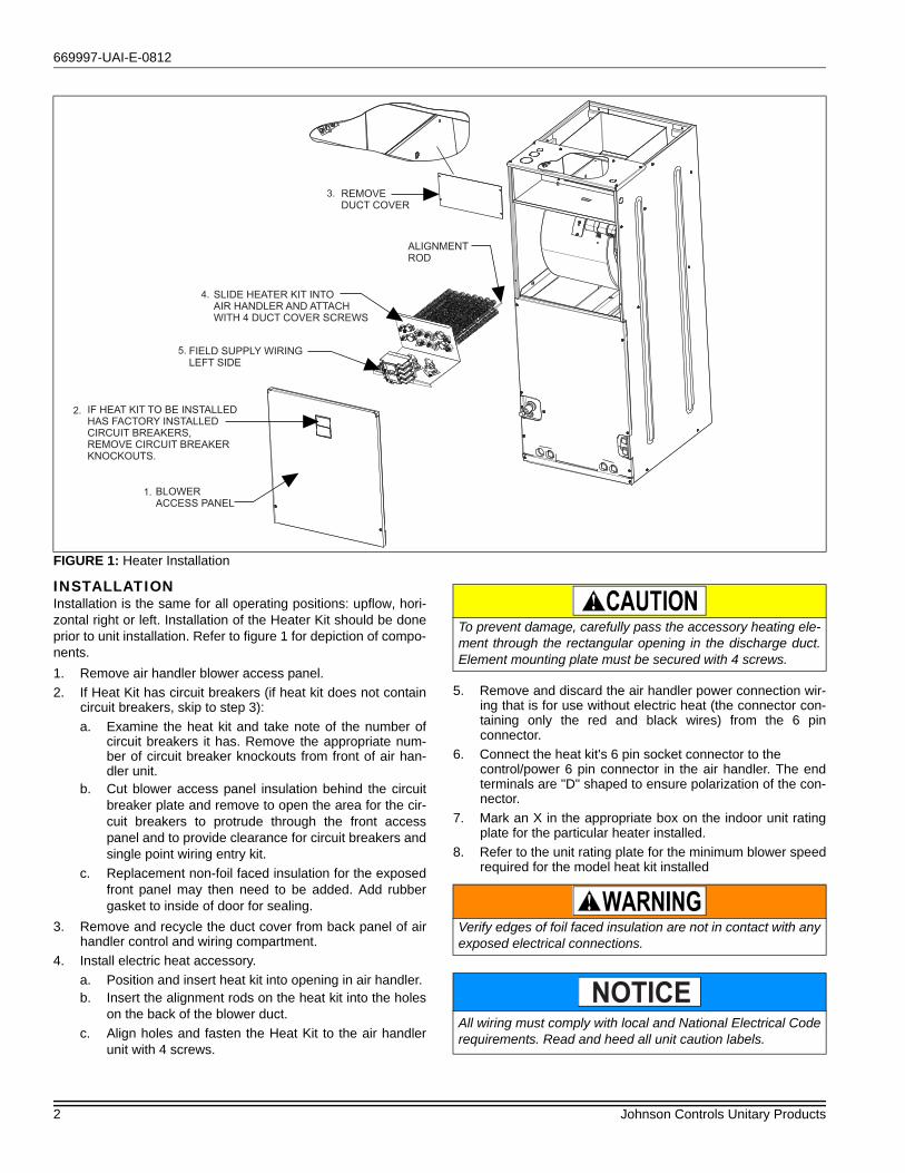
INSTALLATIONInstallation is the same for all operating positions: upflow, hori-zontal right or left. Installation of the Heater Kit should be doneprior to unit installation. Refer to figure 1 for depiction of compo-nents.
1. Remove air handler blower access panel.
2. If Heat Kit has circuit breakers (if heat kit does not containcircuit breakers, skip to step 3):
a. Examine the heat kit and take note of the number ofcircuit breakers it has. Remove the appropriate num-ber of circuit breaker knockouts from front of air han-dler unit.
b. Cut blower access panel insulation behind the circuitbreaker plate and remove to open the area for the cir-cuit breakers to protrude through the front accesspanel and to provide clearance for circuit breakers andsingle point wiring entry kit.
c. Replacement non-foil faced insulation for the exposedfront panel may then need to be added. Add rubbergasket to inside of door for sealing.
3. Remove and recycle the duct cover from back panel of airhandler control and wiring compartment.
4. Install electric heat accessory.
a. Position and insert heat kit into opening in air handler.b. Insert the alignment rods on the heat kit into the holes
on the back of the blower duct.
c. Align holes and fasten the Heat Kit to the air handlerunit with 4 screws.
5. Remove and discard the air handler power connection wir-ing that is for use without electric heat (the connector con-taining only the red and black wires) from the 6 pinconnector.
6. Connect the heat kit's 6 pin socket connector to the control/power 6 pin connector in the air handler. The endterminals are "D" shaped to ensure polarization of the con-nector.
7. Mark an X in the appropriate box on the indoor unit ratingplate for the particular heater installed.
8. Refer to the unit rating plate for the minimum blower speedrequired for the model heat kit installed
FIGURE 1: Heater Installation
FIELD SUPPLY WIRING
LEFT SIDE
5.
SLIDE HEATER KIT INTO
AIR HANDLER AND ATTACH
WITH 4 DUCT COVER SCREWS
4.
BLOWER
ACCESS PANEL
1.
IF HEAT KIT TO BE INSTALLED
HAS FACTORY INSTALLED
CIRCUIT BREAKERS,
REMOVE CIRCUIT BREAKER
KNOCKOUTS.
2.
REMOVE
DUCT COVER
3.
ALIGNMENT
ROD
To prevent damage, carefully pass the accessory heating ele-ment through the rectangular opening in the discharge duct.Element mounting plate must be secured with 4 screws.
Verify edges of foil faced insulation are not in contact with anyexposed electrical connections.
All wiring must comply with local and National Electrical Coderequirements. Read and heed all unit caution labels.
NOTICE

669997-UAI-E-0812
Johnson Controls Unitary Products 3
LINE POWER CONNECTIONSPower may be brought into the unit through the out-let air end ofthe unit (top left when unit is vertical) or the left side panel. Tominimize air leakage, seal the field wiring entry point.
Field wiring connects to heat kits with circuit breaker or terminalblock depending on the heat kit model. The multiple circuit, sin-gle phase heater kits have options for a single power supply.For the 3 phase 20kW and 25kW kits with multiple circuits, asingle point power accessory kit may be ordered separately. Aground lug is also provided on the kits. Refer to unit instructionsfor electrical specifications.
ELECTRIC HEATERS & OPERATING CONTROLS
FIGURE 2: Heat Kit Connection
FACTORY WIRING ATTACHED
TO THIS SIDE
(Do not need to remove)TERMINAL BLOCK OR
CIRCUIT BREAKERS
(May be 1, 2, or 3)
FIELD SUPPLY WIRING WILL
BE ATTACHED TO LEFT SIDE
FIGURE 3: Supply Power Connection
FIELD POWER WIRING
(208/230V)
COMPONENT CODES
GND - GROUND LUG
CB - CIRCUIT BREAKER
CKT - CIRCUIT
CN - WIRE CONNECTOR/NUT
GND
JUMPER BAR
SINGLE SOURCE POWER MULTI-SOURCE POWERMULTI-SOURCE POWER
WITH JUMPER BAR
TERMINAL BLOCK OR
CIRCUIT BREAKER
POWER
SUPPLY POWER
SUPPLY
SINGLE SOURCE POWER
TERMINAL BLOCK OR
CIRCUIT BREAKER
CKT 2
CKT 1
POWER
SUPPLY
CB
CB
CB
CB
CB
2 CIRCUITS ON 13KW-20KW
3 CIRCUITS ON 25KW
POWER
SUPPLY
GNDGND
GNDGND
POWER
SUPPLY
L1
L2
L1
L2
L1L2
CKT 3
L1
L2L1
L2CB
CB
CB
L1
L2
L3
L1
L2
L3
L1
L2
L3
MULTI-SOURCE POWER
CKT 2
CKT 1
2 CIRCUITS ON 13KW-20KW
3 CIRCUITS ON 25KW
1 PHASE ELECTRIC HEAT OPTIONS:
3 PHASE ELECTRIC HEAT POWER OPTIONS:
For blower speed connections, electrical information and wir-ing diagrams, see indoor unit installation instructions.
NOTICE The electric heaters have both auto resettable and one shotthermal limit controls.If failure occurs, this one shot thermal limit control must bereplaced with a direct replacement.
NOTICE

Subject to change without notice. Published in U.S.A. 669997-UAI-E-0812Copyright © 2012 by Johnson Controls, Inc. All rights reserved. Supersedes: 669997-UAI-D-1111
York International Corp.5005 York Drive
Norman, OK 73069
LOW VOLTAGE CONTROL CONNECTIONSThe low voltage transformer and the fan control are standard onall models.
The 24 volt power supply is provided by an internally wired lowvoltage transformer which is standard on all air handler models.
Field supplied low voltage wiring can exit the unit on the topright hand corner or the right hand side panel. Refer to Figure 1.Remove desired knockout and pierce foil faced insulation toallow wiring to pass through. Use as smallest hole possible tominimize air leakage. Install a 7/8" plastic bushing in theselected hole and keep low voltage wiring as short as possibleinside the control box. To further minimize air leakage, seal thewiring entry point at the outside of the unit. The field wiring is tobe connected at the screw terminals of the control board.
All wiring must comply with local and national electrical coderequirements. Read and heed all unit caution labels.
NOTICE
FIGURE 4: Typical Installed Application
UPFLOW
HORIZONTAL RIGHT
HORIZONTAL LEFT
HEAT
HE
AT
HE
AT

![The Order Generated by Implications{0,1}, to fuzzy logic, where the truth values belong to the unit interval [0,1]. In general situation, since [0,1] is a bounded lattice, like in](https://static.fdocuments.us/doc/165x107/5e610a9c561167412703e510/the-order-generated-by-01-to-fuzzy-logic-where-the-truth-values-belong-to-the.jpg)