Electric Fireplace Instruction ManualQuick Reference Guide 1. Prior to installation, please ensure...
22
Electric Fire Wal ww eplace Instruction Ma ll- Mount Fireplace Yosemite Home Décor 1-800-305-9872 ww.YosemiteHomeDecor.com anual
Transcript of Electric Fireplace Instruction ManualQuick Reference Guide 1. Prior to installation, please ensure...

Electric Fireplace Instruction Manual
Wall
www.YosemiteHomeDecor.com
Electric Fireplace Instruction Manual
Wall- Mount Fireplace
Yosemite Home Décor
1-800-305-9872
www.YosemiteHomeDecor.com
Electric Fireplace Instruction Manual

2 | P a g e
Quick Reference Guide
1. Prior to installation, please ensure the rated voltage of your fireplace fits the output
voltage of your outlet.
2. Find a location for the electric fireplace that is protected from direct sunlight.
3. Do not plug the unit into the power outlet before reading all instructions.
NOTE: Light bulbs may become loose during shipping. If the flame effect is dim or does not
work, please check that light bulb or bulbs are finger tight in socket. See instructions for
replacing bulb or bulbs.
NOTE: The electric fireplace heater may emit a slight harmless odor when first turned on. This
odor is a normal condition caused by the initial heating of internal parts and will not occur
again.

3 | P a g e
Table of Content
Important Safety Instructions Page 4
Packing List Page 6
Product Dimensions
Installation Instructions
Electrical Works Instructions
Grounding Instructions
Operation
Maintenance

4 | P a g e
IMPORTANT SAFETY INSTRUCTIONS______________________________________
When using electric fireplaces, basic precautions should always be followed to reduce the risk of
fire, electric shock and injury to persons, including the following:
1. Read all instructions before using this heater.
2. This heater is hot when in use. To avoid burns, do not let bare skin touch hot surfaces, such as
surfaces near the heater outlet or light bulbs. The grill directly in front of the heater outlet
becomes hot during heater operation. If provided, use handles when moving this heater. Keep
combustible materials, such as clothes, pillows, furniture, bedding, papers and curtains at least 3
feet from the front of this appliance.
3. CAUTION: Whenever the heater is left operating and unattended, extreme caution is necessary
if children or invalids are nearby.
4. Do not install the heater directly on carpet or a similar surface, which may restrict air circulation
beneath the unit.
5. Always unplug heater when not in use.
6. To disconnect heater, turn controls to off then remove plug from outlet.
7. Do not use outdoors.
8. This heater is not intended for use in wet locations, such as bathrooms, laundry areas and similar
indoor locations. Never locate heater where it may fall into a bathtub or other water container.
9. Do not operate any heater with a damaged cord or plug, or if the heater has malfunctioned, or if
the heater has been dropped or damaged in any manner. Discard heater, or Return heater to
authorized service for examination, adjustment or repair.
10. Do not run cord under carpeting. Do not cover cord with throw rugs and runners. Arrange cord
away from traffic areas and where it will not be tripped over. Do not route cord under furniture
or appliances
11. Do not insert or allow foreign objects to enter any ventilation or exhaust opening as this may
cause an electric shock, fire, or may damage the heater.
12. To prevent a possible fire, do not block heater outlet or any ventilation or exhaust in any manner.
Do not use on soft surfaces, like a bed, where openings may become blocked.
Front view Upper view
Air outlet 50mmm
250mm
Air inlet 175mm
360mm

5 | P a g e
13. All electrical heaters have hot and arcing or sparking parts inside. Do not use it in areas where
gasoline, paint, or flammable liquids are used or stored or where the unit will be exposed to
flammable vapours.
14. Do not modify this heater. Use it only as described in this manual. Any other use not
recommended by the manufacturer may cause fire, electric shock or injury to persons.
15. Always plug heaters directly into a wall outlet/receptacle. Never use with an extension cord or
relocatable power tap (outlet/power strip).
16. Do not burn wood or other materials in this heater.
17. Do not strike heater glass.
18. Always use a certified electrician should new circuits or outlets be required.
19. Always use properly grounded, fused and polarized outlets.
20. Always use ground fault protection where required by electrical code.
21. Always disconnect power before performing any cleaning, maintenance or relocation of the
heater.
22. When transporting or storing the heater and cord, keep in a dry place and free from excessive
vibration.
23. The heater must not be located immediately below a socket-outlet.
24. This appliance is not intended for use by persons (including children) with reduced physical,
sensory or mental capabilities, or lack of experience and knowledge, unless they have been given
supervision or instruction concerning use of the appliance by a person responsible for their
safety.
25. Children should be supervised to ensure that they do not play with the appliance.
26. Heater is for household use only.

6 | P a g e
PACKING LIST_________________________________________________________________
Parts list Quantity
A. Front Glass/ Glass Face ……………………………………………………………………………………………….. 1
B. Firebox …………………………………………………………………………………………………………………………….. 1
C. Mounting Plate ………………………………………………………………………………………………………………. 1
D. Remote Control ……………………………………………………………………………………………………………… 1
E. Music Remote Control …………………………………………………………………………………………………. 1
(for models: DF-EFP700 & DF-EFP300 only)
F. Instruction Manual ………………………………………………………………………………………………………… 1
G. Coin-cell Battery …………………………………………………………………………………………………………….. 1
H. Fastener Package …………………………………………………………………………………………………………….. 1
7 | P a g e
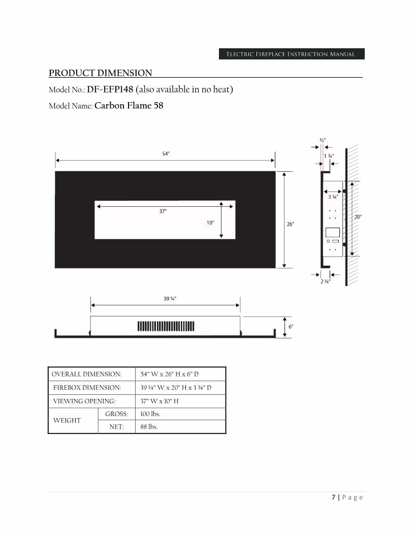
PRODUCT DIMENSION_______________________________________________________
Model No.: DF-EFP148 (also available in no heat)
Model Name: Carbon Flame 58
OVERALL DIMENSION: 54” W x 26” H x 6” D
FIREBOX DIMENSION: 39 ¼” W x 20” H x 3 ¾” D
VIEWING OPENING: 37” W x 10” H
WEIGHT GROSS: 100 lbs.
NET: 88 lbs.

8 | P a g e
Model No.: DF-EFP400
Model Name: Vision 26
OVERALL DIMENSION: 27” W x 28 ½” H x 7” D
FIREBOX DIMENSION: 14 ¼” W x 22” H x 6 ¾” D
VIEWING OPENING: 13 ½” W x 13 ½” H
WEIGHT GROSS: 60 lbs.
NET: 55 lbs.

9 | P a g e
Model No.: DF-EFP600
Model Name: Adobe 59
OVERALL DIMENSION: 58 ¼” W x 26” H x 6 ½” D
FIREBOX DIMENSION: 39 ¼” W x 20” H x 4 ¼” D
VIEWING OPENING: 37” W x 10” H
WEIGHT GROSS: 51 lbs.
NET: 44 lbs.

10 | P a g e
Model No.: DF-EFP700
Model Name: Symphonic Carbon 59
OVERALL DIMENSION: 55” W x 25 ¼” H x 5 ¼” D
FIREBOX DIMENSION: 39 ¼” W x 20” H x 3” D
VIEWING OPENING: 37” W x 10” H
WEIGHT GROSS: 77 lbs.
NET: 68 lbs.

11 | P a g e
Model No.: DF-EFP800
Model Name: Adobe 38
OVERALL DIMENSION: 37 ½” W x 25 ½” H x 7” D
FIREBOX DIMENSION: 22 ¾” W x 20 ¾” H x 4 ½” D
VIEWING OPENING: 20 ¼” W x 10” H
WEIGHT GROSS: 4 6 lbs.
NET: 42 lbs.

12 | P a g e
Model No.: DF-EFP900
Model Name: Carbon Flame 35
OVERALL DIMENSION: 35 ½” W x 20” H x 6” D
FIREBOX DIMENSION: 24 ½” W x 13 ¾” H x 3 ½” D
VIEWING OPENING: 21” W x 11 ¼” H
WEIGHT GROSS: 33 lbs.
NET: 31 lbs.

13 | P a g e
Model No.: DF-EFP1313 (also available in no heat)
Model Name: Hera
OVERALL DIMENSION: 95” W x 26 ½” H x 7” D
FIREBOX DIMENSION: 81” W x 19” H x 6 ¾” D
VIEWING OPENING: 78 ½” W x 10 ½” H
WEIGHT GROSS: 179 lbs.
NET: 158 lbs.

14 | P a g e
INSTALLATION INSTRUCTIONS_____________________________________________
1. The fireplace may be hanged on any wall surface that can support its weight and where it
can be leveled. As it does not irradiate any heat from the back and no rear clearances are
needed.
2. The heater, which is located at the base of the fireplace, must be a minimum of 20 inches
away from any combustible material.
3. It is important that the wall on to which the fireplace is to be installed is of sound
construction. It is recommended that the brackets are installed directly into beams fro
support but not necessary depending on the size and weight of the unit.
4. Yosemite fireplaces are approved for indoor use only.
5. The fireplace must be kept away from any source of damp or moist conditions. Avoid
any close contact with water.
6. This fireplace produces heat. Consequently it is important to ensure that a suitable wall
covering is selected behind and around the appliance. Typical wood frame drywall
construction is suitable.

15 | P a g e
Figure 1
1. Select the position of the fireplace on the wall to which it is to be mounted. Draw a level
horizontal line on the wall at the required height of 25-35 inches from the floor. This line
will correspond to the top of the fireplace so it is important to allow for the extra height
of the glass face.
2. Mark the center line of the fireplace on to the horizontal line.
3. Place the Mounting plate along the horizontal line and line up the center “V” cut out
with the center line. See Figure 1.
4. DRYWALL INSTALLATION
Install screws provided into studs at 4 outside corner screw holes. If studs are not
present, install self drilling hollow wall anchors provided at the 4 outside corners and find wood studs with at least 4 more screws on the mounting plate (two high and two
low). Holes are offset to allow finding wood studs at normal spacing. Attach more
screws into larger models as needed.
5. MASONRY INSTALLATION
If the wall is of a sound masonry construction the attaching holes should be drilled with
a 5/16” masonry drill. First secure the four outside corners. Use the masonry anchors and
screws provided. Double check that a firm, solid attachment is achieved or add
additional anchors as required.

16 | P a g e
6. If a firm attachment cannot be achieved it may be necessary to install extra support to
the framing. It is most important that the mounting plate is firm and solid and that the
structure is capable of holding the weight of the fireplace and glass face.
7. The mounting plate has four location pins, one at each corner of the plate. See Figure 1.
8. Lift the fireplace and place the keyhole slots situated on the back of the fire (Figure 2) to
the location pins on the mounting plate. A gentle application of downward pressure will
lock it into place. Make sure all of the pins have been located into the top section of each
keyhole fixing slot. (See Figures 3 & 4)

17 | P a g e
A. Electrical Works
This fireplace must be grounded
9. A standard electrical outlet must be close to the fireplace. If the electric outlet is required
to be concealed, it can be located above or on the right hand side of the fire and behind
the glass face.
10. DO NOT INSTALL THE FIREPLACE WHERE THE HEATER IS DIRECTLY
ABOVE AN OUTLET
The fireplace’s vent is located in the center of the fireplace base.
11. If the power supply cable becomes damaged in any manner it MUST be replaced.
12. DO NOT connect the fireplace to an extension cord or cable. This can create an unsafe
condition.
13. The fireplace must not be modified in any way or used for purpose other than those
recommended by Yosemite Home Decor.
14. If the fireplace shows any signs of damage it is important that it is examined by a
qualified professional before use is continued.
15. Please observe these instructions as failure to do so may result in electric shock or other
injury.
16. Always ensure that all electrical work complies with the relevant Building Codes. All
electrical work should be carried out by a qualified electrician.
17. If in any doubt contact your supplier or a qualified electrician.

18 | P a g e
B. Attaching the Face
Two people may be required to carry out this installation
1. On each side of the fireplace are two locating studs. (Figure 5)
2. On the back of the face there are two brackets which hooks over these studs
3. Lift the face up to the fireplace. Then lower the face into place so that the brackets on
the rear of the face locate either side of the studs on the fireplace. Once in place firmly
tighten the locking both. (Figure 6)

19 | P a g e
GROUNDING INSTRUCTIONS_______________________________________________
This fireplace is for use on 120 volts. The cord has a plug as shown in (A) at Figure 7. An
adapter as shown in (C) is available for connecting three-blade grounding type plugs to two-slot
receptacles. The green grounding lug extending from the adapter must be connected to a
permanent ground such as a properly grounded outlet box. The adapter should not be used if a
three-slot grounded receptacle is available.
Figure 7

20 | P a g e
OPERATING INSTRUCTIONS________________________________________________ This section will explain the function of each convenient control.
A. Operation by Control Panel
The control panel is located on the right hand side of the fireplace. (Figure 8)
A Main Power Switch
B On/Off Switch
C Flame Effect Dimmer Switch
D Heater Maximum Heat 1500 W
E Heater Low Heat 750 W
There are four indicators on the control panel. See Figure 8
is the power indicator, it lights up when the fireplace insert is working, and turned out when
the fireplace is turned off;
indicates the status of the simulated flame and logs.
indicates the heater is working in low-power status;
Indicates the heater is working in high-power status.

21 | P a g e
B. Operation by Remote Control
1. Prior to use, the handheld remote control requires installation of two (2) AAA batteries
for the old style and/or one (1) coin-cell battery for the new style. Figure 8
2. Remove the cover on the rear of the remote control by sliding backwards. Install the
batteries as shown and then slide the cover back into original position.
3. To enable the remote control to function the power to the fireplace, it must be switch on.
4. At a distance of 4 to 6 feet (1.5 ft to 2 ft.), point the remote control directly towards the
sensor. See Figure 9 & Figure 11
Old Style Remote Control New Style Remote Control
Figure 9 Figure 10 Figure 11
A. Infrared Window
B. On/Off Switch Press on/off switch to turn fire on.

22 | P a g e
C. Flame Effect Dimmer To operate press once to commence dimming cycle.
During the dimming cycle the fire will slowly dim then brighten allowing user to choose
suitable level. Press a second time to stop cycle when the desired level is obtained.
Failure to press dimmer a second time will result in the fire dimming then brightening
cycle repeatedly.
D. Heater Maximum Heat (1500 W) Press this once to switch to high heat. The
indicator light will come on as well as the fan. Press again to turn off. (The fan will
continue to run for a few moments until sensors indicate cool condition).
E. Heater Low Heat (750W) Press this once to switch to low heat. The indicator light
will come on as well as the fan. Press again to turn off. (The fan will continue to run for
a few moments until sensors indicate cool condition).
F. Indicator Lamps will verify current activity. If you are unsure if heat is on or off check
the lamps on the control panel. If the function is On, the indicator lamp