Electric Fireplace DZ1GEC - Valor · Electric Fireplace DZ1GEC Installation Instructions and...
24
Electric Fireplace DZ1GEC Installation Instructions and Owner’s Manual Please read this manual before installing and operating this heater. This manual should remain with the homeowner. Easy to install and operate Operates with or without Heat No pollution, No smoke, No ashes CSA certified Plugs into standard outlet 4001025-04 Miles Industries Ltd. British Columbia, Canada © 2006, Miles Industries Ltd. All rights reserved.
-
Upload
vuongduong -
Category
Documents
-
view
216 -
download
0
Transcript of Electric Fireplace DZ1GEC - Valor · Electric Fireplace DZ1GEC Installation Instructions and...

Electric FireplaceDZ1GEC
Installation Instructions andOwner’s Manual
Please read this manual before installing and operating this heater.This manual should remain with the homeowner.
Easy to install and operate
Operates with or without Heat
No pollution, No smoke, No ashes
CSA certified
Plugs into standard outlet
4001025-04
Miles Industries Ltd.British Columbia, Canada
© 2006, Miles Industries Ltd. All rights reserved.
2
CONGRATULATIONS!
We know that there are a lot of other brands that you could have purchased, and we appreciate that you have chosen a Valor product. Be assured that you have not only selected a superior heater, but also superior service.Your dedicated dealer will maintain the performance and efficiency of your electric heater. All dealers are certified experts and will be happy to answer any questions you may have, so please don’t hesitate to call them as your satisfaction is our number one priority.
Sincerely, Miles Industries Ltd.
Please read and carefully follow all of the instructions found in this manual. Please pay special attention to the safety instructions. The instructions included here will assure that you have many years of dependable and enjoyable service from your electric heater.
Should you encounter an operational problem, call your dealer immediately. Do not try to repair the unit as you may cause an injury or damage the heater.
�
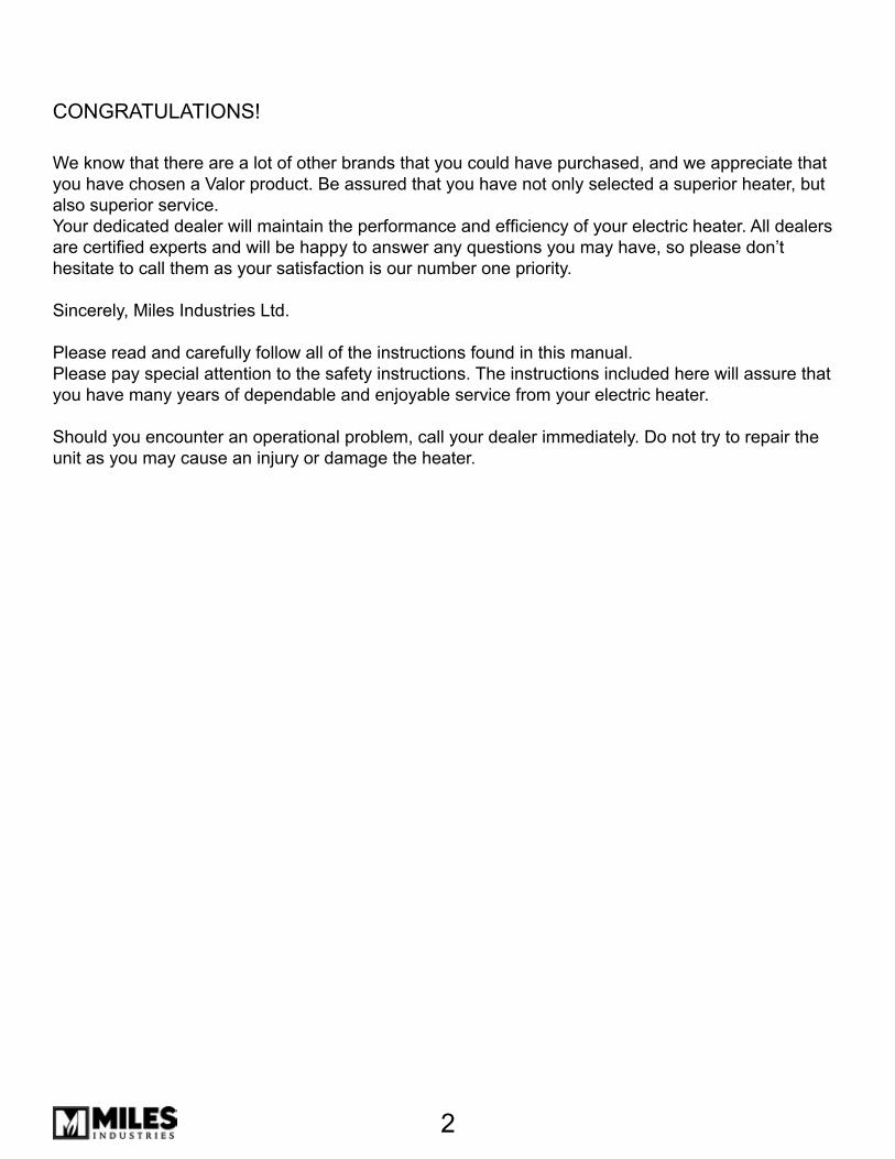
Table of Contents
Safety Information 4Specifications, Dimensions & Clearances 5Testing the Unit 8Grounding 8Installation 8Installation with the Bolero Front 11Installation with the Adorn Front 13Installation with the Arch Fronts 15Operating Instructions 17Maintenance 19Spare Parts List 21Spare Parts Diagram 22Wiring Diagram 23Warranty 24
4
Safety Information
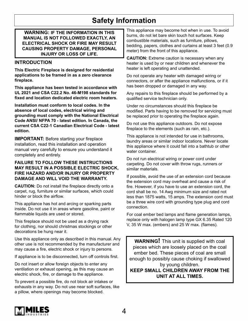
INTRODUCTIONThis Electric Fireplace is designed for residential applications to be framed in as a zero clearance fireplace.
This appliance has been tested in accordance with UL 2021 and CSA C22.2 No. 46-M198 standards for fixed and location dedicated electric room heaters.
Installation must conform to local codes. In the absence of local codes, electrical wiring and grounding must comply with the National Electrical Code ANSI/ NFPA 70 - latest edition. In Canada, the current CSA C22-1 Canadian Electrical Code - latest edition.
IMPORTANT: Before starting your fireplace installation, read this installation and operation manual very carefully to ensure you understand it completely and entirely.
FAILURE TO FOLLOW THESE INSTRUCTIONS MAY RESULT IN A POSSIBLE ELECTRIC SHOCK, FIRE HAZARD AND/OR INJURY OR PROPERTY DAMAGE AND WILL VOID THE WARRANTY.CAUTION: Do not install the fireplace directly onto a carpet, rug, furniture or similar surfaces, which could hinder or block the airflow.
This appliance has hot and arcing or sparking parts inside. Do not use it in areas where gasoline, paint or flammable liquids are used or stored.
This fireplace should not be used as a drying rack for clothing, nor should christmas stockings or other decorations be hung near it.
Use this appliance only as described in this manual. Any other use is not recommended by the manufacturer and may cause a fire, electric shock or injury to persons.
If appliance is to be disconnected, turn off controls first.
Do not insert or allow foreign objects to enter any ventilation or exhaust opening, as this may cause an electric shock, fire, or damage to the appliance.
To prevent a possible fire, do not block air intakes or exhausts in any way. Do not use near soft surfaces, like a pillow, where openings may become blocked.
This appliance may become hot when in use. To avoid burns, do not let bare skin touch hot surfaces. Keep combustible materials, such as furniture, pillows, bedding, papers, clothes and curtains at least � feet (0.9 meter) from the front of this appliance.
CAUTION: Extreme caution is necessary when any heater is used by or near children and whenever the heater is left operating and unattended.
Do not operate any heater with damaged wiring or connectors, or after the appliance malfunctions, or if it has been dropped or damaged in any way.
Any repairs to this fireplace should be performed by a qualified service technician only.
Under no circumstances should this fireplace be modified. Parts having to be removed for servicing must be replaced prior to operating the fireplace again.
Do not use this appliance outdoors. Do not expose fireplace to the elements (such as rain, etc.).
This appliance is not intended for use in bathrooms, laundry areas or similar indoor locations. Never locate this appliance where it could fall into a bathtub or other water container.
Do not run electrical wiring or power cord under carpeting. Do not cover with throw rugs, runners or similar materials.
If possible, avoid the use of an extension cord because the extension cord may overheat and cause a risk of fire. However, if you have to use an extension cord, the cord shall be no. 14 Awg minimum size and rated not less than 1875 watts, 15 amps. The extension cord must be a three wire cord with grounding type plug and cord connection.
For coal ember bed lamps and flame generation lamps, replace only with halogen lamp type GX 6.�5 Rated 120 V, 35 W max. (embers) and 25 W max. (flames).
WARNING! This unit is supplied with coal pieces which are loosely placed on the coal ember bed. These pieces of coal are small
enough to possibly cause choking if swallowed by young children.
KEEP SMALL CHILDREN AWAY FROM THE UNIT AT ALL TIMES.
WARNING: IF THE INFORMATION IN THIS MANUAL IS NOT FOLLOWED EXACTLY, AN ELECTRICAL SHOCK OR FIRE MAY RESULT CAUSING PROPERTY DAMAGE, PERSONAL
INJURY OR LOSS OF LIFE.
5
Specifications, Dimensions & Clearances
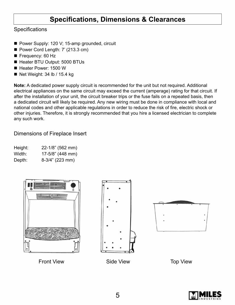
Top ViewFront View Side View
Specifications
Power Supply: 120 V; 15-amp grounded, circuitPower Cord Length: 7’ (21�.� cm)Frequency: 60 HzHeater BTU Output: 5000 BTUsHeater Power: 1500 WNet Weight: �4 lb / 15.4 kg
Note: A dedicated power supply circuit is recommended for the unit but not required. Additional electrical appliances on the same circuit may exceed the current (amperage) rating for that circuit. If after the installation of your unit, the circuit breaker trips or the fuse fails on a repeated basis, then a dedicated circuit will likely be required. Any new wiring must be done in compliance with local and national codes and other applicable regulations in order to reduce the risk of fire, electric shock or other injuries. Therefore, it is strongly recommended that you hire a licensed electrician to complete any such work.
Dimensions of Fireplace Insert
Height: 22-1/8” (562 mm)Width: 17-5/8” (448 mm)Depth: 8-�/4” (22� mm)
6
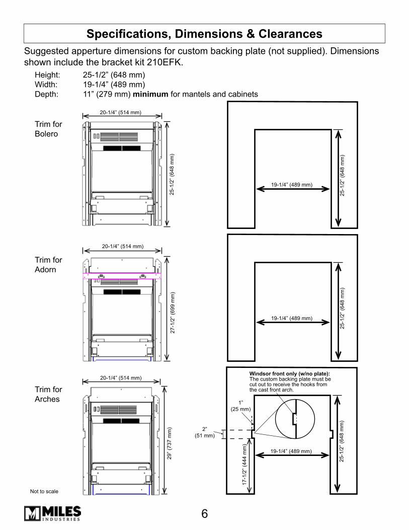
Specifications, Dimensions & ClearancesSuggested apperture dimensions for custom backing plate (not supplied). Dimensions shown include the bracket kit 210EFK.
Trim for Arches
Trim for Bolero
Trim for Adorn
Height: 25-1/2” (648 mm)Width: 19-1/4” (489 mm)Depth: 11” (279 mm) minimum for mantels and cabinets
20-1/4” (514 mm)
25-1
/2” (
648
mm
)
25-1
/2” (
648
mm
)
29” (
7�7
mm
)
19-1/4” (489 mm)
25-1
/2” (
648
mm
)
19-1/4” (489 mm)
25-1
/2” (
648
mm
)
19-1/4” (489 mm)
27-1
/2” (
699
mm
)
20-1/4” (514 mm)
20-1/4” (514 mm)Windsor front only (w/no plate): The custom backing plate must be cut out to receive the hooks from the cast front arch.
17-1
/2” (
444
mm
)
2”(51 mm)
1”(25 mm)
Not to scale
7
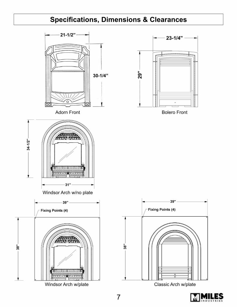
Bolero FrontAdorn Front
Specifications, Dimensions & Clearances
Windsor Arch w/no plate
Classic Arch w/plateWindsor Arch w/plate
8
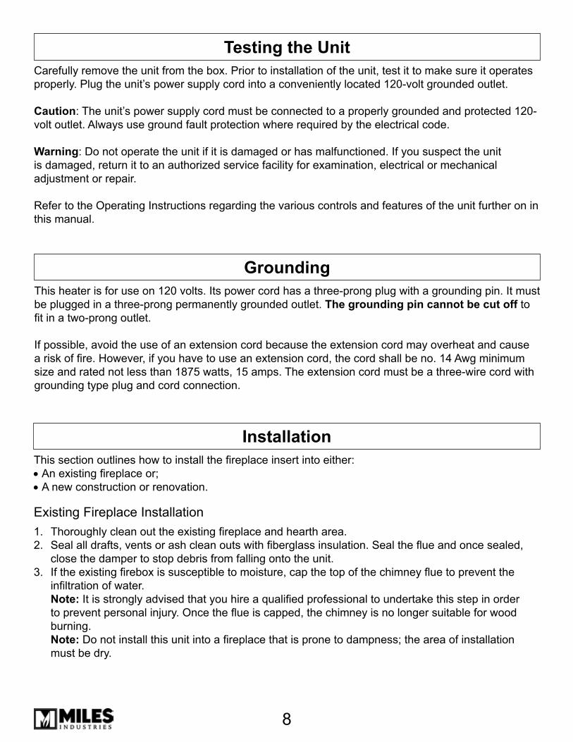
This section outlines how to install the fireplace insert into either:• An existing fireplace or;• A new construction or renovation.
Existing Fireplace InstallationThoroughly clean out the existing fireplace and hearth area.Seal all drafts, vents or ash clean outs with fiberglass insulation. Seal the flue and once sealed, close the damper to stop debris from falling onto the unit.If the existing firebox is susceptible to moisture, cap the top of the chimney flue to prevent the infiltration of water. Note: It is strongly advised that you hire a qualified professional to undertake this step in order to prevent personal injury. Once the flue is capped, the chimney is no longer suitable for wood burning. Note: Do not install this unit into a fireplace that is prone to dampness; the area of installation must be dry.
1.2.
�.
GroundingThis heater is for use on 120 volts. Its power cord has a three-prong plug with a grounding pin. It must be plugged in a three-prong permanently grounded outlet. The grounding pin cannot be cut off to fit in a two-prong outlet.
If possible, avoid the use of an extension cord because the extension cord may overheat and cause a risk of fire. However, if you have to use an extension cord, the cord shall be no. 14 Awg minimum size and rated not less than 1875 watts, 15 amps. The extension cord must be a three-wire cord with grounding type plug and cord connection.
Testing the UnitCarefully remove the unit from the box. Prior to installation of the unit, test it to make sure it operates properly. Plug the unit’s power supply cord into a conveniently located 120-volt grounded outlet.
Caution: The unit’s power supply cord must be connected to a properly grounded and protected 120-volt outlet. Always use ground fault protection where required by the electrical code.
Warning: Do not operate the unit if it is damaged or has malfunctioned. If you suspect the unit is damaged, return it to an authorized service facility for examination, electrical or mechanical adjustment or repair.
Refer to the Operating Instructions regarding the various controls and features of the unit further on in this manual.
Installation
9
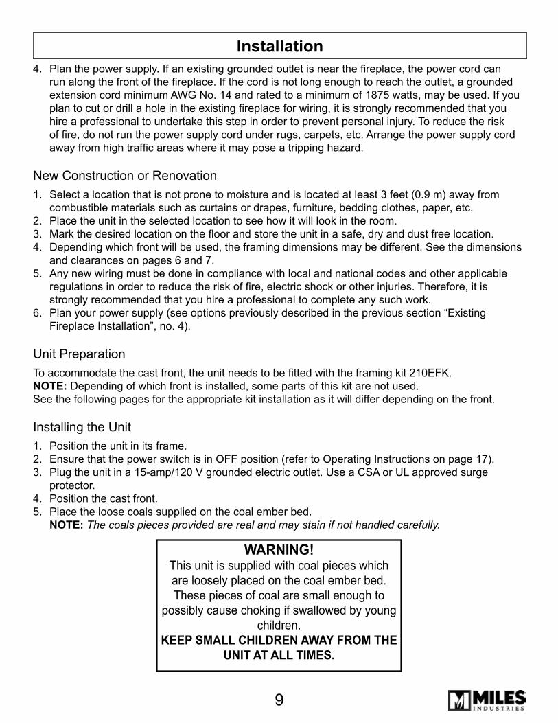
InstallationPlan the power supply. If an existing grounded outlet is near the fireplace, the power cord can run along the front of the fireplace. If the cord is not long enough to reach the outlet, a grounded extension cord minimum AWG No. 14 and rated to a minimum of 1875 watts, may be used. If you plan to cut or drill a hole in the existing fireplace for wiring, it is strongly recommended that you hire a professional to undertake this step in order to prevent personal injury. To reduce the risk of fire, do not run the power supply cord under rugs, carpets, etc. Arrange the power supply cord away from high traffic areas where it may pose a tripping hazard.
New Construction or RenovationSelect a location that is not prone to moisture and is located at least � feet (0.9 m) away from combustible materials such as curtains or drapes, furniture, bedding clothes, paper, etc. Place the unit in the selected location to see how it will look in the room. Mark the desired location on the floor and store the unit in a safe, dry and dust free location.Depending which front will be used, the framing dimensions may be different. See the dimensions and clearances on pages 6 and 7. Any new wiring must be done in compliance with local and national codes and other applicable regulations in order to reduce the risk of fire, electric shock or other injuries. Therefore, it is strongly recommended that you hire a professional to complete any such work.Plan your power supply (see options previously described in the previous section “Existing Fireplace Installation”, no. 4).
Unit PreparationTo accommodate the cast front, the unit needs to be fitted with the framing kit 210EFK.NOTE: Depending of which front is installed, some parts of this kit are not used.See the following pages for the appropriate kit installation as it will differ depending on the front.
Installing the UnitPosition the unit in its frame.Ensure that the power switch is in OFF position (refer to Operating Instructions on page 17).Plug the unit in a 15-amp/120 V grounded electric outlet. Use a CSA or UL approved surge protector.Position the cast front.Place the loose coals supplied on the coal ember bed. NOTE: The coals pieces provided are real and may stain if not handled carefully.
4.
1.
2.�.4.
5.
6.
1.2.�.
4.5.
WARNING!This unit is supplied with coal pieces which are loosely placed on the coal ember bed. These pieces of coal are small enough to
possibly cause choking if swallowed by young children.
KEEP SMALL CHILDREN AWAY FROM THE UNIT AT ALL TIMES.
10
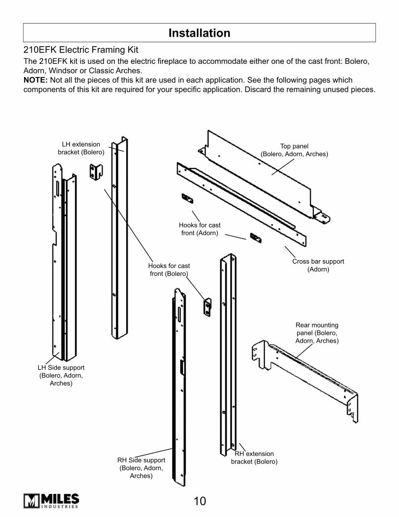
Installation210EFK Electric Framing Kit
Top panel(Bolero, Adorn, Arches)
RH extension bracket (Bolero)
LH extension bracket (Bolero)
RH Side support (Bolero, Adorn,
Arches)
Rear mounting panel (Bolero, Adorn, Arches)
LH Side support (Bolero, Adorn,
Arches)
Cross bar support (Adorn)
Hooks for cast front (Adorn)
Hooks for cast front (Bolero)
The 210EFK kit is used on the electric fireplace to accommodate either one of the cast front: Bolero, Adorn, Windsor or Classic Arches.NOTE: Not all the pieces of this kit are used in each application. See the following pages which components of this kit are required for your specific application. Discard the remaining unused pieces.
11
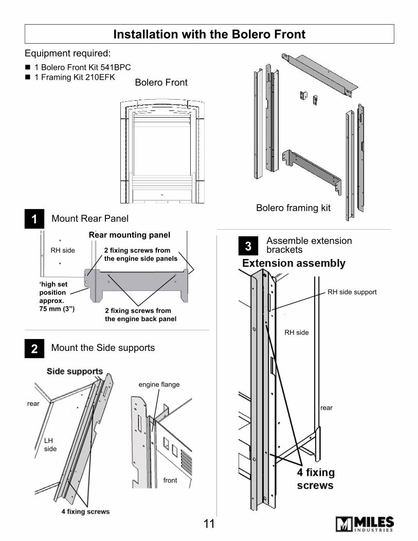
Installation with the Bolero FrontEquipment required:
1 Bolero Front Kit 541BPC1 Framing Kit 210EFK
Mount the Side supports
Mount Rear Panel
Assemble extension brackets
1
2
3
Bolero Front
Bolero framing kit
Rear mounting panel
‘high set position approx.75 mm (3”) 2 fixing screws from
the engine back panel
RH side
engine flange
front
LH side
rear
RH side
2 fixing screws from the engine side panels
RH side support
rear

12
Change hooks on cast front5
Complete bracket assembly
Installation with the Bolero Front
Assemble top panel4
Assemble front to fireplace6
rear view
rear view
rear view
1�
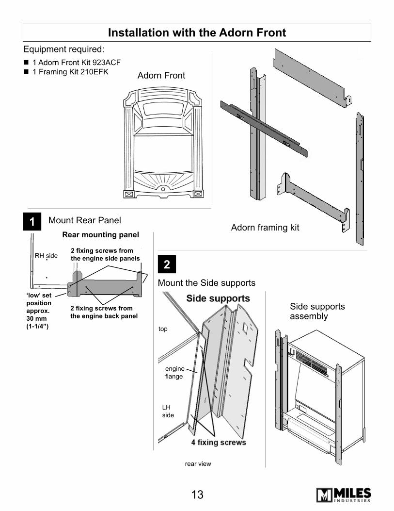
Installation with the Adorn Front
Mount Rear Panel1
Mount the Side supports
2
Equipment required:1 Adorn Front Kit 92�ACF1 Framing Kit 210EFK
Adorn Front
Side supports assembly
Adorn framing kit
RH side
‘low’ set position approx.30 mm (1-1/4”)
2 fixing screws from the engine back panel
Rear mounting panel
2 fixing screws from the engine side panels
engine flange
LH side
top
rear view
14
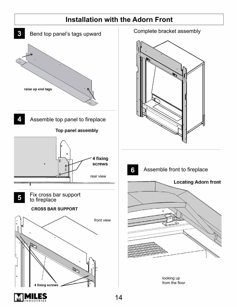
Installation with the Adorn Front
Bend top panel’s tags upward3
Assemble top panel to fireplace4
Complete bracket assembly
Assemble front to fireplace6
Fix cross bar support to fireplace5
rear view
front view
looking up from the floor

15
Installation with the Arch FrontsEquipment required:
1 Windsor Arch Kit 5�9AFB or 5�9AFP (w/plate) or1 Windsor Arch Kit 549AFB or 5�9AFP (w/out plate) or1 Classic Arch Kit 550CAP (w/plate)1 Framing Kit 210EFK
Mount Rear Panel1
Mount the Side Supports2
Windsor ArchWindsor Arch w/plate
Arch framing kit
Rear mounting panel
‘high set position approx.75 mm (3”) 2 fixing screws from
the engine back panel
RH side 2 fixing screws from the engine side panels
engine flange
LH side
top
rear view
Classic Arch w/plate

16
Installation with the Arch Fronts
Assemble outer casting or backing plate to fireplace5
Complete bracket assembly
Assemble top panel to fireplace
4
Bend top panel’s tags downward
3
Hook inner casting to outer casting or backing plate6
rear view
rear view
17
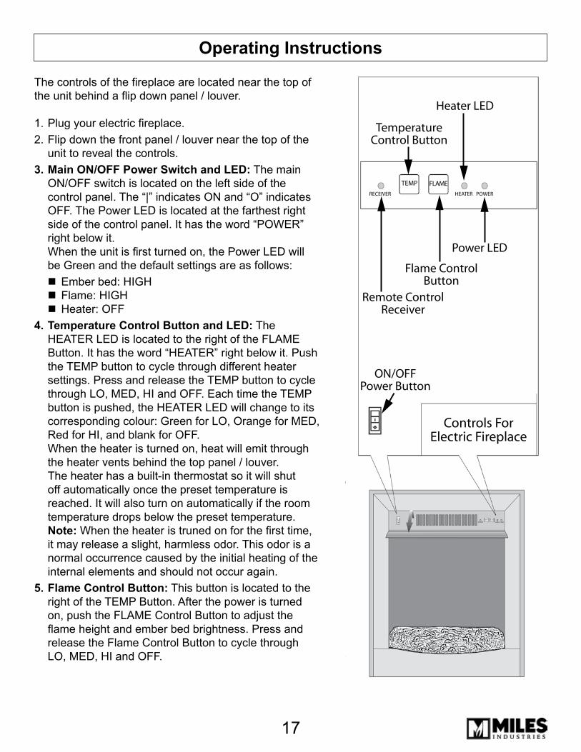
Operating Instructions
The controls of the fireplace are located near the top of the unit behind a flip down panel / louver.
Plug your electric fireplace.Flip down the front panel / louver near the top of the unit to reveal the controls.Main ON/OFF Power Switch and LED: The main ON/OFF switch is located on the left side of the control panel. The “|” indicates ON and “O” indicates OFF. The Power LED is located at the farthest right side of the control panel. It has the word “POWER” right below it. When the unit is first turned on, the Power LED will be Green and the default settings are as follows:
Ember bed: HIGHFlame: HIGHHeater: OFF
Temperature Control Button and LED: The HEATER LED is located to the right of the FLAME Button. It has the word “HEATER” right below it. Push the TEMP button to cycle through different heater settings. Press and release the TEMP button to cycle through LO, MED, HI and OFF. Each time the TEMP button is pushed, the HEATER LED will change to its corresponding colour: Green for LO, Orange for MED, Red for HI, and blank for OFF. When the heater is turned on, heat will emit through the heater vents behind the top panel / louver. The heater has a built-in thermostat so it will shut off automatically once the preset temperature is reached. It will also turn on automatically if the room temperature drops below the preset temperature. Note: When the heater is truned on for the first time, it may release a slight, harmless odor. This odor is a normal occurrence caused by the initial heating of the internal elements and should not occur again.Flame Control Button: This button is located to the right of the TEMP Button. After the power is turned on, push the FLAME Control Button to adjust the flame height and ember bed brightness. Press and release the Flame Control Button to cycle through LO, MED, HI and OFF.
1.2.
3.
4.
5.
Heater LED
TemperatureControl Button
Power LED
Flame ControlButton
Remote ControlReceiver
ON/OFFPower Button
Controls ForElectric Fireplace
RECEIVER HEATER POWER
TEMP FLAME
TEMP FLAME
HEATER POWERRECEIVER
18
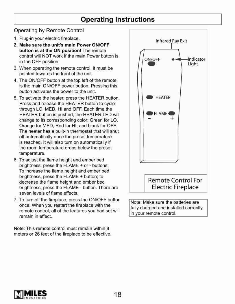
Operating InstructionsOperating by Remote Control
Plug-in your electric fireplace.Make sure the unit’s main Power ON/OFF button is at the ON position! The remote control will NOT work if the main Power button is in the OFF position.When operating the remote control, it must be pointed towards the front of the unit.The ON/OFF button at the top left of the remote is the main ON/OFF power button. Pressing this button activates the power to the unit.To activate the heater, press the HEATER button. Press and release the HEATER button to cycle through LO, MED, HI and OFF. Each time the HEATER button is pushed, the HEATER LED will change to its corresponding color: Green for LO, Orange for MED, Red for HI, and blank for OFF. The heater has a built-in thermostat that will shut off automatically once the preset temperature is reached. It will also turn on automatically if the room temperature drops below the preset temperature.To adjust the flame height and ember bed brightness, press the FLAME + or - buttons. To increase the flame height and ember bed brightness, press the FLAME + button; to decrease the flame height and ember bed brightness, press the FLAME - button. There are seven levels of flame effects.To turn off the fireplace, press the ON/OFF button once. When you restart the fireplace with the remote control, all of the features you had set will remain in effect.
Note: This remote control must remain within 8 meters or 26 feet of the fireplace to be effective.
1.2.
�.
4.
5.
6.
7.
Infrared Ray Exit
IndicatorLight
ON/OFF
HEATER
FLAME+-
Remote Control ForElectric Fireplace
Note: Make sure the batteries are fully charged and installed correctly in your remote control.
19
MaintenanceWarning: The unit must be unplugged from the power supply prior to any maintenance or cleaning in order to reduce the risk electric shock or fire.
Light Bulb Replacement Procedure
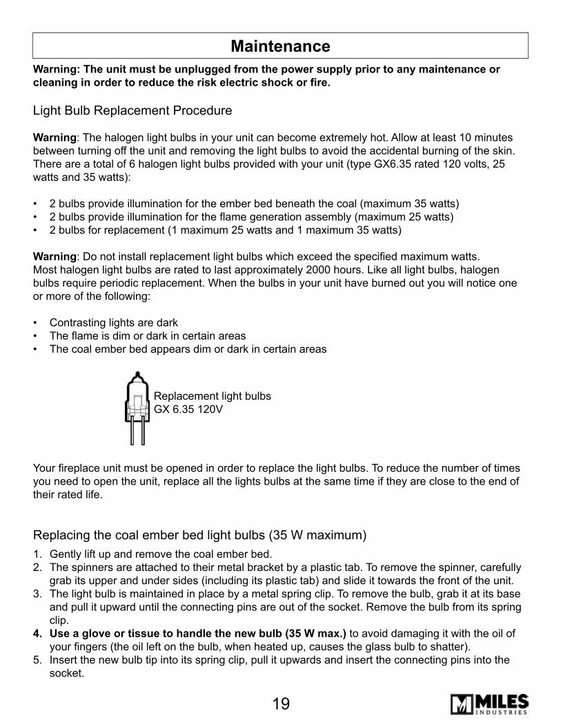
Warning: The halogen light bulbs in your unit can become extremely hot. Allow at least 10 minutes between turning off the unit and removing the light bulbs to avoid the accidental burning of the skin. There are a total of 6 halogen light bulbs provided with your unit (type GX6.�5 rated 120 volts, 25 watts and �5 watts):
2 bulbs provide illumination for the ember bed beneath the coal (maximum 35 watts)2 bulbs provide illumination for the flame generation assembly (maximum 25 watts)2 bulbs for replacement (1 maximum 25 watts and 1 maximum 35 watts)
Warning: Do not install replacement light bulbs which exceed the specified maximum watts.Most halogen light bulbs are rated to last approximately 2000 hours. Like all light bulbs, halogen bulbs require periodic replacement. When the bulbs in your unit have burned out you will notice one or more of the following:
Contrasting lights are dark The flame is dim or dark in certain areasThe coal ember bed appears dim or dark in certain areas
Your fireplace unit must be opened in order to replace the light bulbs. To reduce the number of times you need to open the unit, replace all the lights bulbs at the same time if they are close to the end of their rated life.
•••
•••
Replacement light bulbs GX 6.�5 120V
Replacing the coal ember bed light bulbs (35 W maximum)Gently lift up and remove the coal ember bed.The spinners are attached to their metal bracket by a plastic tab. To remove the spinner, carefully grab its upper and under sides (including its plastic tab) and slide it towards the front of the unit.The light bulb is maintained in place by a metal spring clip. To remove the bulb, grab it at its base and pull it upward until the connecting pins are out of the socket. Remove the bulb from its spring clip.Use a glove or tissue to handle the new bulb (35 W max.) to avoid damaging it with the oil of your fingers (the oil left on the bulb, when heated up, causes the glass bulb to shatter).Insert the new bulb tip into its spring clip, pull it upwards and insert the connecting pins into the socket.
1.2.
�.
4.
5.
20
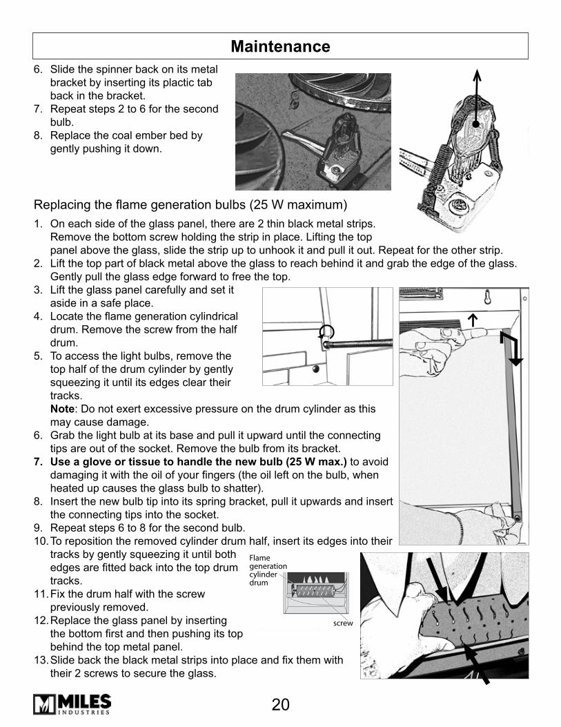
MaintenanceSlide the spinner back on its metal bracket by inserting its plactic tab back in the bracket.Repeat steps 2 to 6 for the second bulb.Replace the coal ember bed by gently pushing it down.
Replacing the flame generation bulbs (25 W maximum)On each side of the glass panel, there are 2 thin black metal strips. Remove the bottom screw holding the strip in place. Lifting the top panel above the glass, slide the strip up to unhook it and pull it out. Repeat for the other strip.Lift the top part of black metal above the glass to reach behind it and grab the edge of the glass. Gently pull the glass edge forward to free the top.Lift the glass panel carefully and set it aside in a safe place.Locate the flame generation cylindrical drum. Remove the screw from the half drum.To access the light bulbs, remove the top half of the drum cylinder by gently squeezing it until its edges clear their tracks. Note: Do not exert excessive pressure on the drum cylinder as this may cause damage.Grab the light bulb at its base and pull it upward until the connecting tips are out of the socket. Remove the bulb from its bracket.Use a glove or tissue to handle the new bulb (25 W max.) to avoid damaging it with the oil of your fingers (the oil left on the bulb, when heated up causes the glass bulb to shatter).Insert the new bulb tip into its spring bracket, pull it upwards and insert the connecting tips into the socket.Repeat steps 6 to 8 for the second bulb.To reposition the removed cylinder drum half, insert its edges into their tracks by gently squeezing it until both edges are fitted back into the top drum tracks. Fix the drum half with the screw previously removed.Replace the glass panel by inserting the bottom first and then pushing its top behind the top metal panel.Slide back the black metal strips into place and fix them with their 2 screws to secure the glass.
6.
7.
8.
1.
2.
�.
4.
5.
6.
7.
8.
9.10.
11.
12.
1�.
Flamegenerationcylinderdrum
screw

21
Spare Parts List
Valor Electric Fireplace
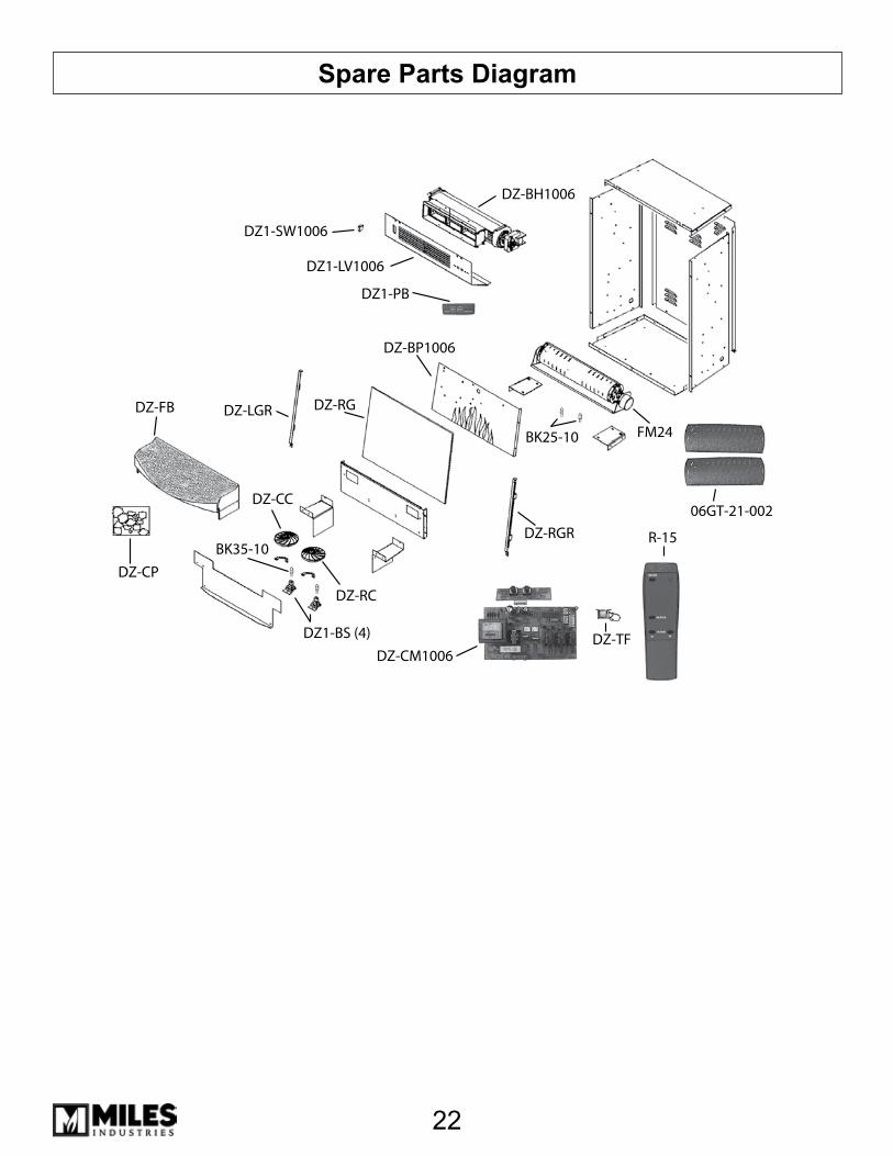
Part Number Quantity DescriptionDZ-RG 1 Rear Glass (Mirror)DZ-BP1006 1 Back Panel (control board, wires, and switches)DZ-BH1006 1 Blower and Heating Element Assembly (cord and plug)BK25-10 10 Bulb Kit (25 W Halogen) for drum flameBK�5-10 10 Bulb Kit (�5 W Halogen) for ember bed06GT-21-002 2 Flame Cylinder Drum CoverDZ-TF 1 TransformerDZ-FS 1 FuseDZ1-LV1006 1 Louver PanelDZ1-BS 4 Light Bulb SocketsDZ-CP 1 Coal packDZ-CC 1 LH Spinner (clear cap)DZ-RC 1 RH Spinner (red cap)FM24 1 24 rpm motorDZ-LGR 1 LH glass retainerDZ-RGR 1 RH glass retainerDZ-FB 1 Fuel bed mouldingR-15 1 Black remote controlDZ-CM1006 1 Circuit BoardDZ-RS 1 Remote Control SensorDZ-SW1006 1 Main ON/OFF SwitchDZ-PO 1 Potentiometer (not shown)
22
Spare Parts Diagram
DZ-BP1006
06GT-21-002
R-15
DZ-CM1006
BK35-10
BK25-10
DZ1-LV1006
DZ1-PB
DZ-BH1006
FM24
DZ-CC
DZ-RC
DZ-CP
DZ-FB DZ-LGR
DZ-RGR
DZ-TF
DZ-RG
DZ1-SW1006
DZ1-BS (4)
2�
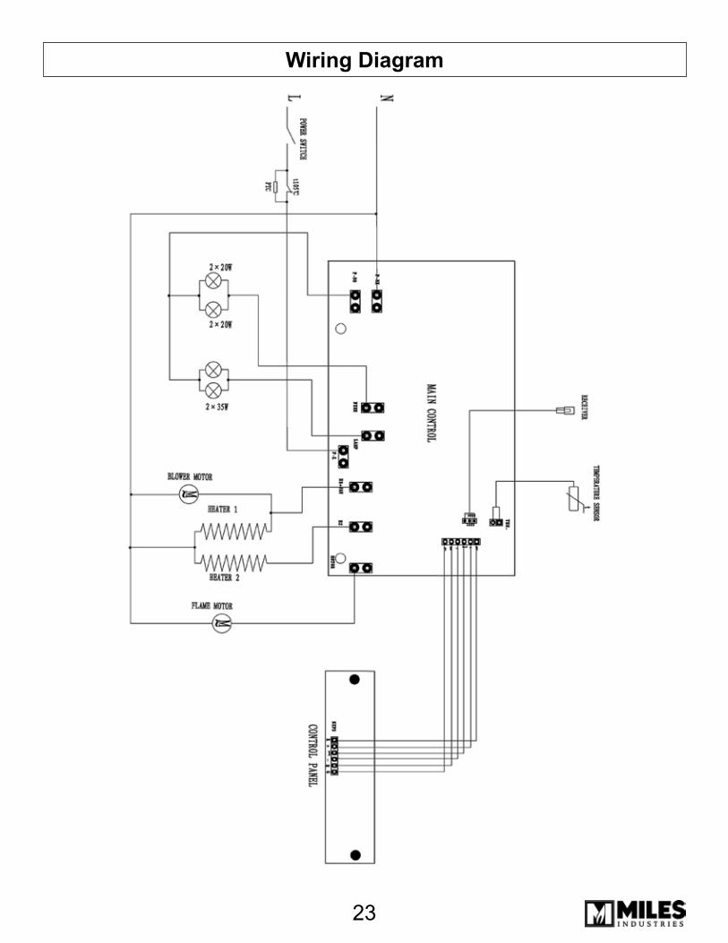
Wiring Diagram

24
WarrantyThis electric fireplace was inspected, tested and carefully packaged to minimize the chance of dam-age during shipment. If a part (excluding light bulbs*) within one year from the date of purchase proves to be defective in material or fabrication under normal use, the part will be repaired or re-placed. The Company’s obligation under the warranty is to replace or repair defective parts or to re-fund the purchase price. Any expenses or damage resulting from the installation, removal or transpor-tation of the product will the responsibility of the owner and are not covered by this warranty. Defects must be reported to the authorized dealer where the product was purchased. The owner assumes all other risks arising out from the use or misuse of the product. The warranty will be void if the product damage or failure is deemed by the Company to be caused by accident, alteration, misuse, abuse, incorrect installation or removal, or connection to an incorrect power source by the owner. The Com-pany neither assumes, nor authorizes any person or entity to assume for it any obligation or liability associated with its products.
* Light bulbs are not covered under this warranty
Miles Industries Ltd.British Columbia, Canada
© 2006, Miles Industries Ltd. All rights reserved.