Electric Current Note
21
Electric Current. Symbol I Electric current is the flow of electric charge. An electric current is a flow of electrons from one point to another . For an elect ric current to f low there are two requirements (i) A source of electrons e.g. electric cell which is a source of electrons and also electrical energy which causes the electrons to flow (ii) Current will only f low in an electric c ircuit only if there is a complete circuit. S.I. unit of current : Ampere Amp A If energy is used in when a current flows through a material then that material has what we call resistance. esistance is defined as that which opposes the flow of electric current. S.I. unit of electric resistance : !hms Ω Electrons flow from the negati"e side of an electric cell to the positi"e side.
description
Electric symbol and notes
Transcript of Electric Current Note
7/21/2019 Electric Current Note
http://slidepdf.com/reader/full/electric-current-note 1/21
Electric Current. Symbol I
Electric current is the flow of electric charge.
An electric current is a flow of electrons from one
point to another. For an electric current to flow there
are two requirements
(i) A source of electrons e.g. electric cell which is a
source of electrons and also electrical energy whichcauses the electrons to flow
(ii) Current will only flow in an electric circuit only if
there is a complete circuit.
S.I. unit of current : Ampere Amp A
If energy is used in when a current flows through a
material then that material has what we call resistance.
esistance is defined as that which opposes the flow of
electric current.
S.I. unit of electric resistance : !hms Ω
Electrons flow from the negati"e side of an electric
cell to the positi"e side.
7/21/2019 Electric Current Note
http://slidepdf.com/reader/full/electric-current-note 2/21
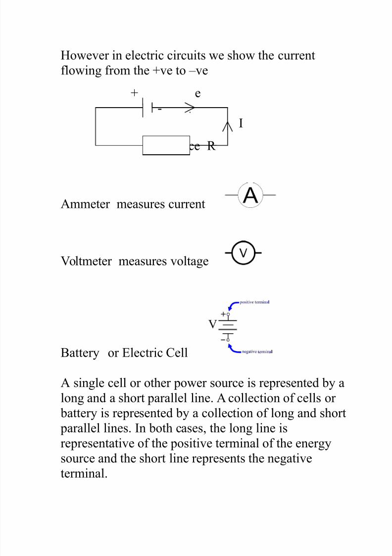
#owe"er in electric circuits we show the current
flowing from the $"e to %"e
$ e &
I
esistance
Ammeter measures current
'oltmeter measures "oltage
attery or Electric Cell
A single cell or other power source is represented y along and a short parallel line. A collection of cells or
attery is represented y a collection of long and short
parallel lines. In oth cases* the long line is
representati"e of the positi"e terminal of the energy
source and the short line represents the negati"e
terminal.
7/21/2019 Electric Current Note
http://slidepdf.com/reader/full/electric-current-note 3/21
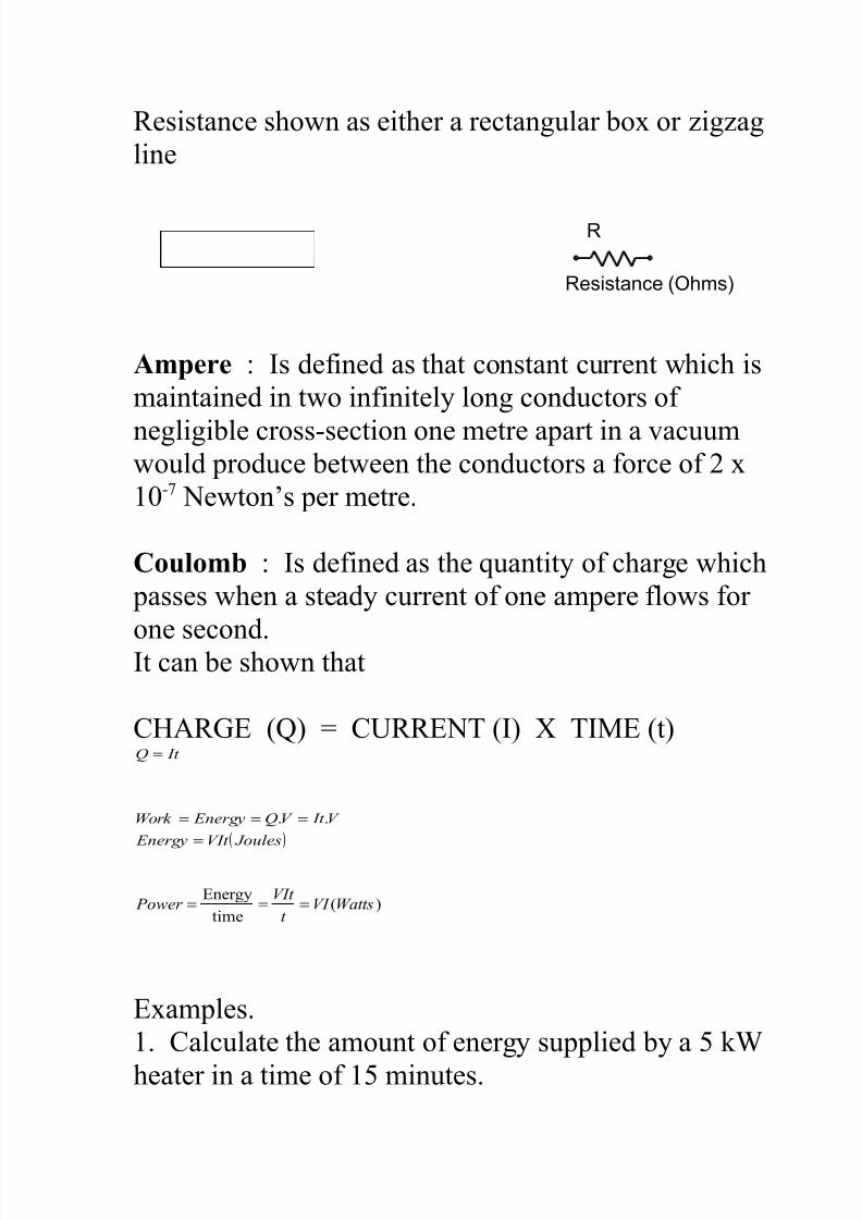
esistance shown as either a rectangular o+ or ,ig,ag
line
R
Resistance (Ohms)
Ampere : Is defined as that constant current which is
maintained in two infinitely long conductors of
negligile cross§ion one metre apart in a "acuumwould produce etween the conductors a force of - +
/&0 1ewton2s per metre.
Coulomb : Is defined as the quantity of charge which
passes when a steady current of one ampere flows for
one second.It can e shown that
C#A3E (4) 5 C6E17 (I) 8 7I9E (t) It Q =
( ) JoulesVIt Energy
V It V Q EnergyWork
=
=== ..
)(time
EnergyWattsVI
t
VIt Power ===
E+amples.
. Calculate the amount of energy supplied y a ;<
heater in a time of minutes.
7/21/2019 Electric Current Note
http://slidepdf.com/reader/full/electric-current-note 4/21
-. #ow long will it ta;e a - ;< ;ettle to oil -// g of
water initially of -/o C.
=. If the p.d. across an electrical heater is -/ ' and its
electrical power is ; < calculate the current flowing.
>. If the power rating of a heater is // < and the
current flowing through it is A calculate the p.d.
across it.
OHM’S LAW.
7he current flowing through a conductor is directly
proportional to the potential difference across its ends
7/21/2019 Electric Current Note
http://slidepdf.com/reader/full/electric-current-note 5/21
pro"ided that the temperature remains constant I
∝ ' at constant temperature
7he constant of proportionality is the resistance of the
conductor IRV =
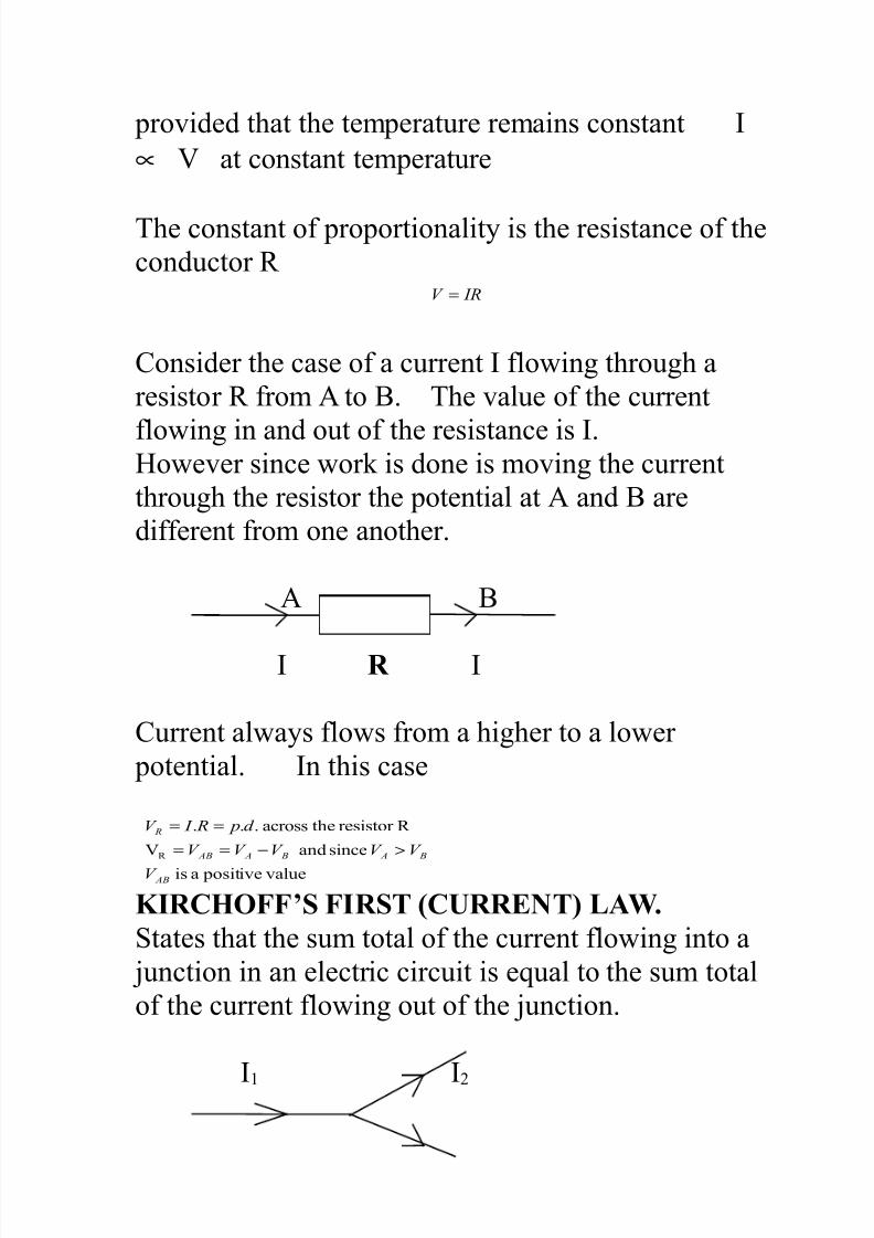
Consider the case of a current I flowing through a
resistor from A to . 7he "alue of the current
flowing in and out of the resistance is I.#owe"er since wor; is done is mo"ing the current
through the resistor the potential at A and are
different from one another.
A
I R I
Current always flows from a higher to a lower
potential. In this case
"alue positi"eais
sinceand '
resistortheacross...
AB
B A B A AB
R
V
V V V V V
d p R I V
>−==
==
KIRCHOFF’S FIRST (CRRE!T" LAW.
States that the sum total of the current flowing into a
?unction in an electric circuit is equal to the sum total
of the current flowing out of the ?unction.
I I-
7/21/2019 Electric Current Note
http://slidepdf.com/reader/full/electric-current-note 6/21
I=
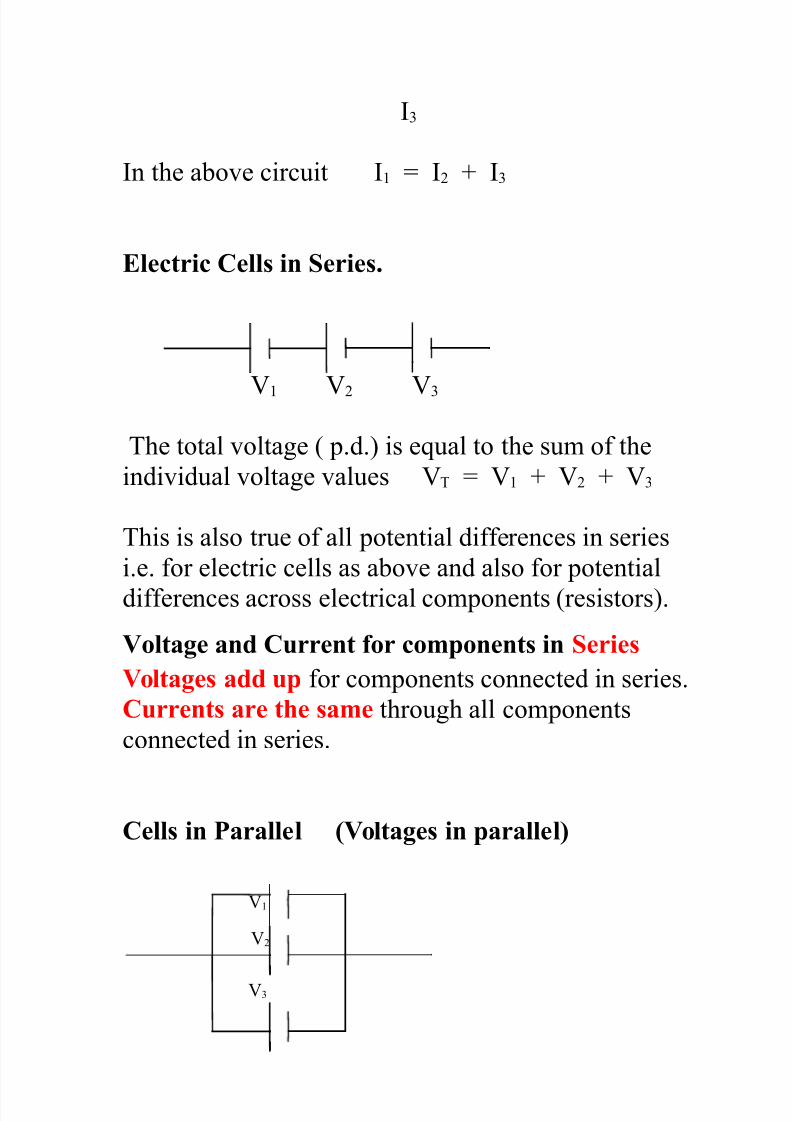
In the ao"e circuit I 5 I- $ I=
Electric Cell# in Serie#.
' '- '=
7he total "oltage ( p.d.) is equal to the sum of the
indi"idual "oltage "alues '7 5 ' $ '- $ '=
7his is also true of all potential differences in series
i.e. for electric cells as ao"e and also for potential
differences across electrical components (resistors).
$olt%&e %n' Current or component# in Serie#
$olt%&e# %'' up for components connected in series.
Current# %re t)e #%me through all components
connected in series.
Cell# in *%r%llel ($olt%&e# in p%r%llel"
'
'-
'=
7/21/2019 Electric Current Note
http://slidepdf.com/reader/full/electric-current-note 7/21
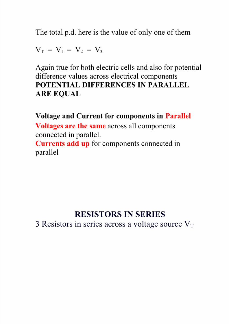
7he total p.d. here is the "alue of only one of them
'7 5 ' 5 '- 5 '=
Again true for oth electric cells and also for potential
difference "alues across electrical components
*OTE!TIAL +IFFERE!CES I! *ARALLEL
ARE E,AL
$olt%&e %n' Current or component# in *%r%llel
$olt%&e# %re t)e #%me across all components
connected in parallel.
Current# %'' up for components connected in
parallel
RESISTORS I! SERIES
= esistors in series across a "oltage source '7
7/21/2019 Electric Current Note
http://slidepdf.com/reader/full/electric-current-note 8/21
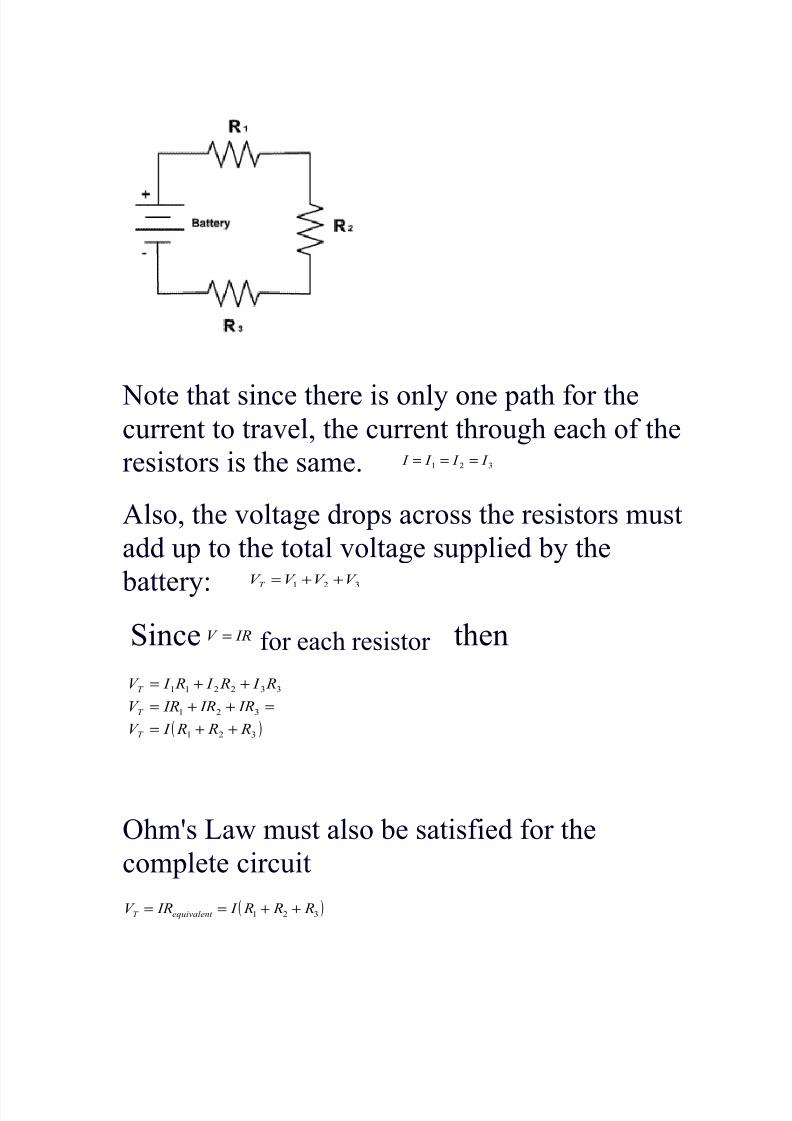
1ote that since there is only one path for thecurrent to tra"el* the current through each of the
resistors is the same. =-. I I I I ===
Also* the "oltage drops across the resistors must
add up to the total "oltage supplied y the
attery:=- V V V V T ++=
Since IRV = for each resistor then
( )=-.
=-.
==--..
R R R I V
IR IR IRV
R I R I R I V
T
T
T
++=
=++=
++=
!hm@s aw must also e satisfied for the
complete circuit
( )=-. R R R I IRV equivalent T ++==
7/21/2019 Electric Current Note
http://slidepdf.com/reader/full/electric-current-note 9/21
7herefore the e+pression for equi"alent resistance
for = resistors connected in series is
=- R R R Requivalent ++=
In general* the equi"alent resistance of resistors
connected in series is the sum of their resistances.
7hat is for n resistors in series the equi"alent
resistance is
∑=
=n
i
iequivalent R R.
R ESISTORS I! *ARALLEL
esistors can e connected such that they ranch
out from a single point (;nown as a no'e)* and
?oin up again somewhere else in the circuit. If we
lael the point at the $ side of the attery A and
the point at the % side of the attery and
7/21/2019 Electric Current Note
http://slidepdf.com/reader/full/electric-current-note 10/21
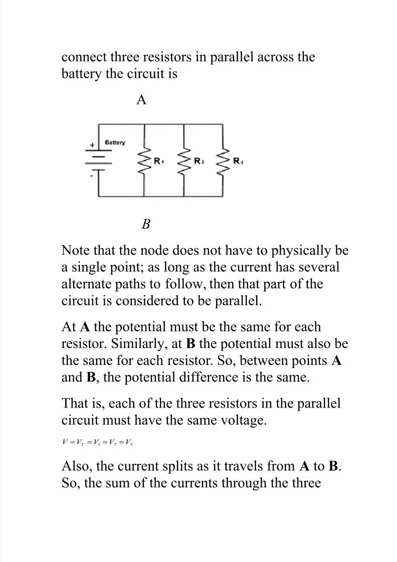
connect three resistors in parallel across the
attery the circuit is
A
B
1ote that the node does not ha"e to physically e
a single pointB as long as the current has se"eral
alternate paths to follow* then that part of the
circuit is considered to e parallel.
At A the potential must e the same for each
resistor. Similarly* at - the potential must also e
the same for each resistor. So* etween points A
and -* the potential difference is the same.
7hat is* each of the three resistors in the parallel
circuit must ha"e the same "oltage.
=- V V V V V T ====
Also* the current splits as it tra"els from A to -.
So* the sum of the currents through the three
7/21/2019 Electric Current Note
http://slidepdf.com/reader/full/electric-current-note 11/21
ranches is the same as the current at A and at -
(where the currents from the ranch reunite).
=-. I I I I ++=
y !hm@s aw and recalling that all the "oltages
are equal the equation is equi"alent to:
=-.=
=
-
-
.
.
R
V
R
V
R
V
R
V
R
V
R
V
R
V
equivalent
++=++=
As the "oltages are equal. So the 'oltages cancelout* and we are left with
∑=
=
++=
n
i iequivalent
equivalent
R R
or
R R R R
=-
7he general equation for any numer of resistors
connected in parallel.
!ne prolem with this equation is that the
solution gi"e the in"erse "alue of equi"alent and so
you must rememer to re&in"ert the "alue to
determine equi"alent
#owe"er If the numer of resistors in parallel is
- the equation ecomes
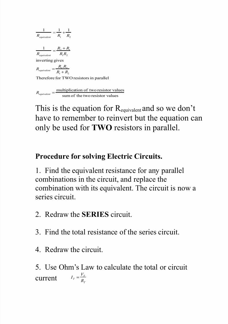
7/21/2019 Electric Current Note
http://slidepdf.com/reader/full/electric-current-note 12/21
aluesresistor "twotheof sum
aluesresistor "twoof tionmultiplica
parallelinresistors7<!for7herefore
.
gi"esin"erting
-
-
-
-
-
=
+=
+=
+=
equivalent
equivalent
equivalent
equivalent
R
R R
R R R
R R
R R
R
R R R
7his is the equation for equi"alent and so we don2t
ha"e to rememer to rein"ert ut the equation can
only e used for TWO resistors in parallel.
*roce'ure or #olin& Electric Circuit#.
. Find the equi"alent resistance for any parallelcominations in the circuit* and replace the
comination with its equi"alent. 7he circuit is now a
series circuit.
-. edraw the SERIES circuit.
=. Find the total resistance of the series circuit.
>. edraw the circuit.
. 6se !hm2s aw to calculate the total or circuit
currentT
T T
R
V I =
7/21/2019 Electric Current Note
http://slidepdf.com/reader/full/electric-current-note 13/21
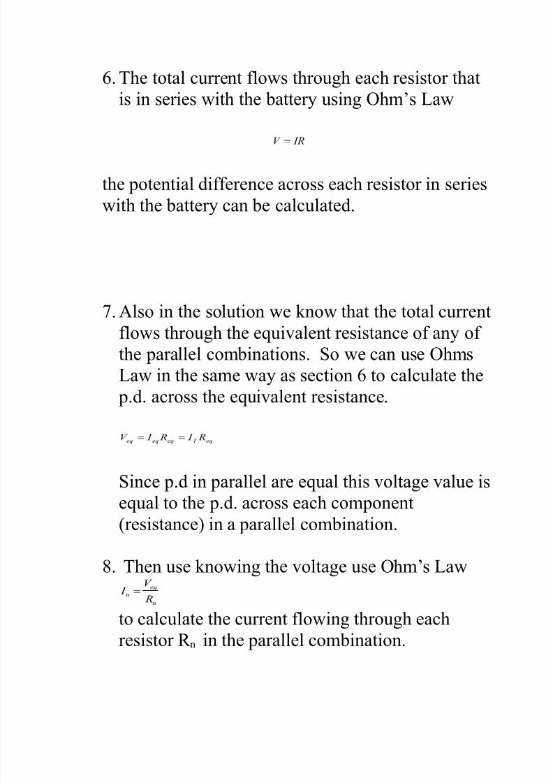
. 7he total current flows through each resistor that
is in series with the attery using !hm2s aw
IRV =
the potential difference across each resistor in series
with the attery can e calculated.
0. Also in the solution we ;now that the total current
flows through the equi"alent resistance of any of
the parallel cominations. So we can use !hms
aw in the same way as section to calculate the
p.d. across the equi"alent resistance.
eqT eqeqeq R I R I V ==
Since p.d in parallel are equal this "oltage "alue is
equal to the p.d. across each component
(resistance) in a parallel comination.
D. 7hen use ;nowing the "oltage use !hm2s aw
n
eq
n R
V I =
to calculate the current flowing through each
resistor n in the parallel comination.
7/21/2019 Electric Current Note
http://slidepdf.com/reader/full/electric-current-note 14/21
. 7o calculate the power dissipated through any
component (resistance) use the equation.
VI Power =
7/21/2019 Electric Current Note
http://slidepdf.com/reader/full/electric-current-note 15/21
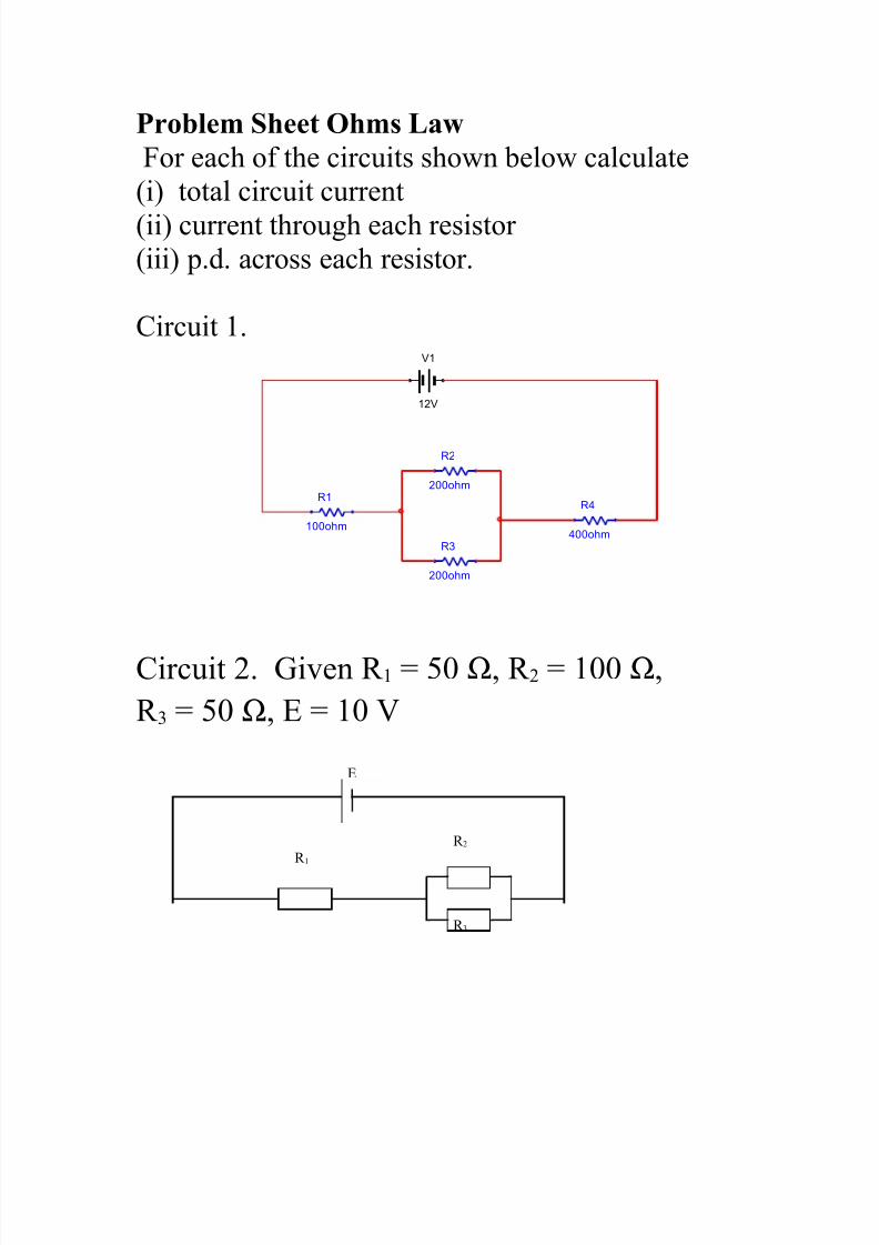
*roblem S)eet O)m# L%/
For each of the circuits shown elow calculate
(i) total circuit current
(ii) current through each resistor(iii) p.d. across each resistor.
Circuit .V1
12V
R1
100ohm
R3
200ohm
R2
200ohm
R4
400ohm
Circuit -. 3i"en 5 / Ω* - 5 // Ω*
= 5 / Ω* E 5 / '
E
-
=
7/21/2019 Electric Current Note
http://slidepdf.com/reader/full/electric-current-note 16/21
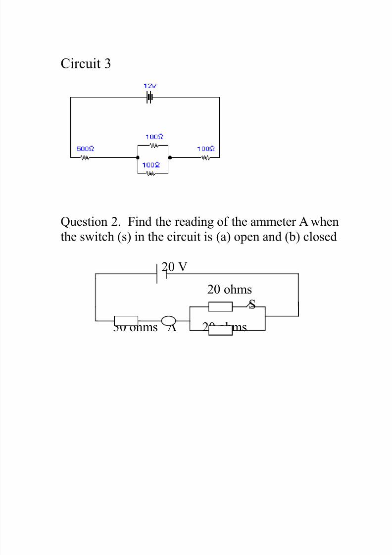
Circuit =
4uestion -. Find the reading of the ammeter A when
the switch (s) in the circuit is (a) open and () closed
-/ '
-/ ohms S
=/ ohms A -/ ohms
7/21/2019 Electric Current Note
http://slidepdf.com/reader/full/electric-current-note 17/21
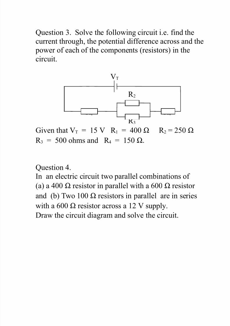
4uestion =. Sol"e the following circuit i.e. find the
current through* the potential difference across and the
power of each of the components (resistors) in the
circuit.
'7
-
> =
3i"en that '7 5 ' 5 >// Ω - 5 -/ Ω
= 5 // ohms and > 5 / Ω.
4uestion >.In an electric circuit two parallel cominations of
(a) a >// Ω resistor in parallel with a // Ω resistor
and () 7wo // Ω resistors in parallel are in series
with a // Ω resistor across a - ' supply.
raw the circuit diagram and sol"e the circuit.
7/21/2019 Electric Current Note
http://slidepdf.com/reader/full/electric-current-note 18/21
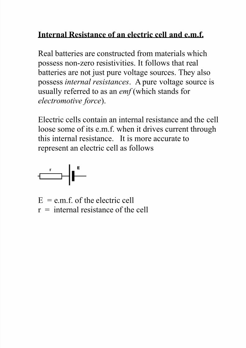
Intern%l Re#i#t%nce o %n electric cell %n' e.m..
eal atteries are constructed from materials which
possess non&,ero resisti"ities. It follows that real atteries are not ?ust pure "oltage sources. 7hey also
possess internal resistances. A pure "oltage source is
usually referred to as an e! (which stands forelectrootive !orce).
Electric cells contain an internal resistance and the cellloose some of its e.m.f. when it dri"es current through
this internal resistance. It is more accurate to
represent an electric cell as follows
E 5 e.m.f. of the electric cell
r 5 internal resistance of the cell
7/21/2019 Electric Current Note
http://slidepdf.com/reader/full/electric-current-note 19/21
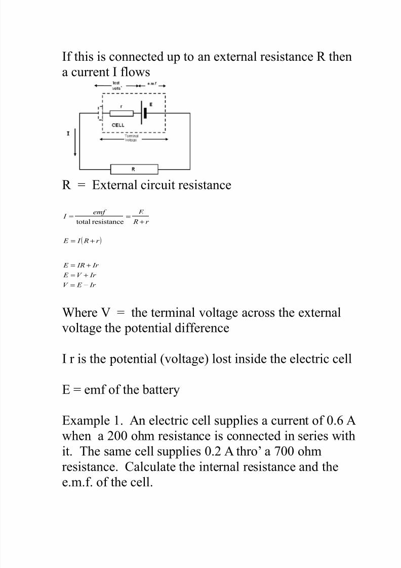
If this is connected up to an e+ternal resistance then
a current I flows
5 E+ternal circuit resistance
( )r R I E
r R
E e! I
+=
+==
resistancetotal
Ir E V
Ir V E
Ir IR E
−=
+=
+=
<here ' 5 the terminal "oltage across the e+ternal
"oltage the potential difference
I r is the potential ("oltage) lost inside the electric cell
E 5 emf of the attery
E+ample . An electric cell supplies a current of /. A
when a -// ohm resistance is connected in series with
it. 7he same cell supplies /.- A thro2 a 0// ohm
resistance. Calculate the internal resistance and the
e.m.f. of the cell.
7/21/2019 Electric Current Note
http://slidepdf.com/reader/full/electric-current-note 20/21
-. A cell can supply(a) a current of .- A thro2 two -/
ohm resistors when they are connected in parallel and
() a current of /.> A when they are in series.
Calculate the e.m.f. internal resistance of the cell andthe p.d. of the attery for (a) and ()
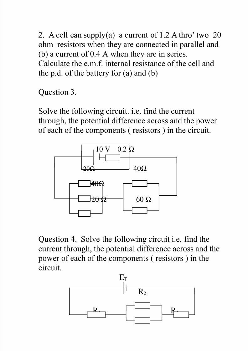
4uestion =.
Sol"e the following circuit. i.e. find the current
through* the potential difference across and the powerof each of the components ( resistors ) in the circuit.
/ ' /.- Ω
-/Ω 40Ω
40Ω
20 Ω 60 Ω
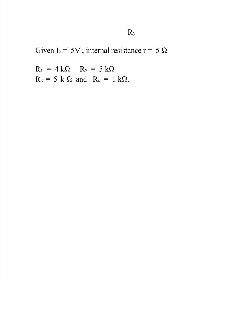
4uestion >. Sol"e the following circuit i.e. find the
current through* the potential difference across and the power of each of the components ( resistors ) in the
circuit.
E7
-
>
7/21/2019 Electric Current Note
http://slidepdf.com/reader/full/electric-current-note 21/21
=
3i"en E 5' * internal resistance r 5 Ω
5 > ; Ω - 5 ; Ω
= 5 ; Ω and > 5 ; Ω.
![PPU 960 Physics Note [Sem 2 Chapter 14 - Electric Current]](https://static.fdocuments.us/doc/165x107/577ce0011a28ab9e78b27c28/ppu-960-physics-note-sem-2-chapter-14-electric-current.jpg)