Electric Circuits. 1970
28
= Telecom Australia ENGINEERING TRAINll\!G 210 Kingsway South Melbourne 3205 Training Publication ETP 0075 ELECTRIC CIRCUITS PUBLISHED 1970 PREVIOUSLY RGP 002 1. INTRODUCTION .. 2. ELECTRIC CIRCUITS 3. OHM'S LAW 4. KIRCHOFF'S LAWS 5. SERIES CIRCUITS 6. PARALLEL CIRCUITS 7, SERIES-PARALLEL CIRCUITS 8. USING RESISTORS TO CONTROL CURRENT AND VOLT.AGE 1 2 4 6 9 9. POWER AND ENETIGY IN ELR(;'J'RTC CJRCUITS 10, ELECTRIC SUPPLY SOURCES ll, INTRODUCTION TO EQUIVALENT CIRCUITS 12. MAXIMUM POWER TRANSFER 13. TEST QUESTIONS 11 14 15 18 21 25 26 28 1. INTRODUCTION. 1.1 An electric current will flow when an electric potential is connected a continuous conducting path called a circuit, The number of components included in the circuit varies according to what the circuit is designed to do, but generally, most electric circuits include: • a source of voltage such as a battery or generator; • apparatus, such as a lamp or bell, to be operated by the current; • controlling and protective devices such as switches and fuses. In addition, electric circuits often include measuring instruments such as ammeters and voltmeters, so that the operating conditions in the circuit can be checked. ,. 10/0895
Transcript of Electric Circuits. 1970

=Telecom Australia ENGINEERING TRAINll\!G 210 Kingsway South Melbourne 3205
Training Publication ETP 0075
ELECTRIC CIRCUITS PUBLISHED 1970
PREVIOUSLY RGP 002
1. INTRODUCTION ..
2. ELECTRIC CIRCUITS
3. OHM'S LAW
4. KIRCHOFF'S LAWS
5. SERIES CIRCUITS
6. PARALLEL CIRCUITS
7, SERIES-PARALLEL CIRCUITS
8. USING RESISTORS TO CONTROL CURRENT AND VOLT.AGE
1
2
4
6
9
9. POWER AND ENETIGY IN ELR(;'J'RTC CJRCUITS
10, ELECTRIC SUPPLY SOURCES
ll, INTRODUCTION TO EQUIVALENT CIRCUITS
12. MAXIMUM POWER TRANSFER
13. TEST QUESTIONS
11
14
15
18
21
25
26
28
1. INTRODUCTION.
1.1 An electric current will flow when an electric potential is connected a continuous conducting path called a circuit, The number of components included
in the circuit varies according to what the circuit is designed to do, but generally, most electric circuits include:
• a source of voltage such as a battery or generator;
• apparatus, such as a lamp or bell, to be operated by the current;
• controlling and protective devices such as switches and fuses.
In addition, electric circuits often include measuring instruments such as ammeters and voltmeters, so that the operating conditions in the circuit can be checked.
,. 10/0895
ELECTRIC CIRCUITS
1.2 Modern telecom systems are usually made up from a number of smaller units, each designed to do a certain job. The electric circuit of each unit often consists
of the combination of many smaller circuits, each of vh.i ch plays its part in the overall operation. A knowledge of the principles of electric circuits is therefore essential to the understanding of the operation of telecom equipment, as the performance of the system as a whole depends to a large extent on each of the smaller circuits working correctly.
1.3 This paper describes the characteristics of the basic types of electric circuits, and defines and explains the rules and laws governing their operation.
2. ELECTRIC CIRCUITS.
2.1 The term "circuit" refers to the complete path for electric current, including the source of voltage, the connecting wires and the circuit components.
2.2 CIRCUIT DIAGRAMS. Whenever it is necessary to represent an electric circuit diagramatically, the circuit components are shown by standard symbols joined by
lines to represent the connecting wires. These diagrams are called schematic circuit diagrams, or more commonly, schematic circuits.
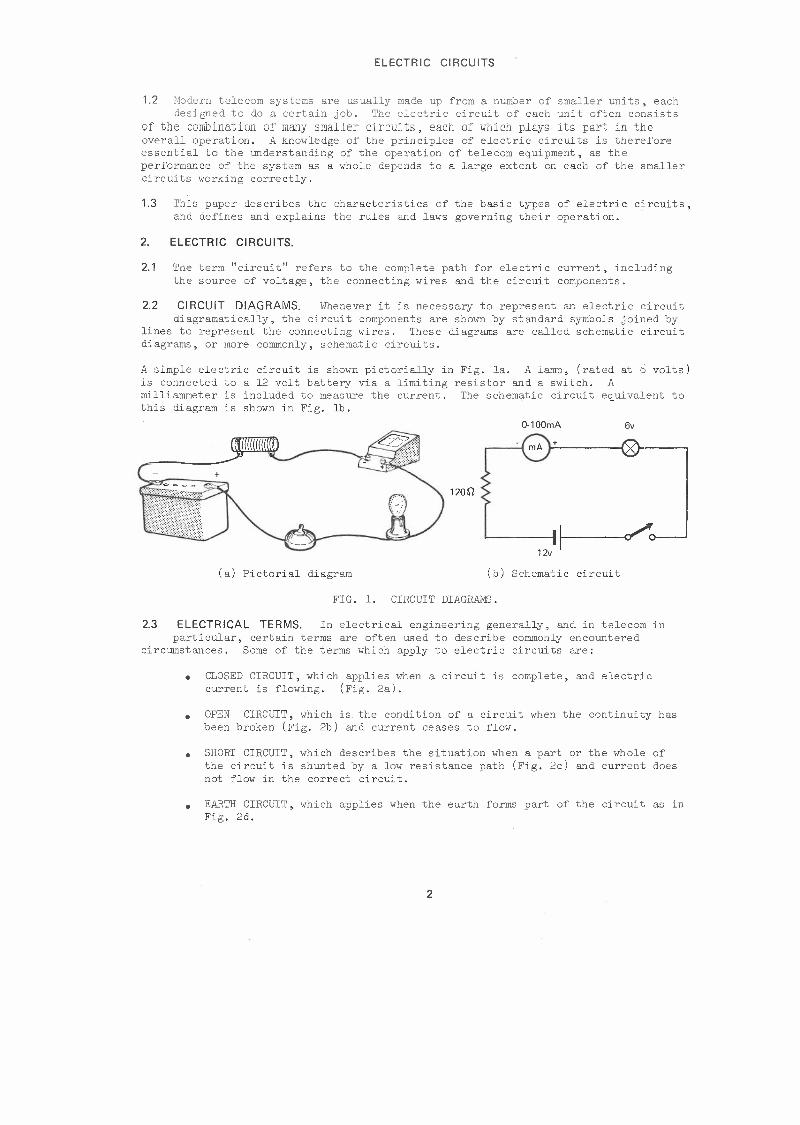
A simple electric circuit is shown pictorially in Fig. la. A lamp, (rated at 6 volts) is connected to a 12 volt battery via a limiting resistor and a switch. A milliammeter is included to measure the current. The schematic circuit equivalent to this diagram is shown in Fig. lb.
0-100mA
120n
6v
~ mA ) + (X i-------,
•' ,./,. 12v~ C
(a) Pictorial diagram (b) Schematic circuit
FIG. 1. CIRCUIT DIAGRAMS.
2.3 ELECTRICAL TERMS. In electrical engineering generally, and in telecom in particular, certain terms are often used to describe commonly encountered
circumstances. Some of the terms which apply to electric circuits are:
• CLOSED CIRCUIT, which applies when a circuit is complete, and electric current is flowing. (Fig. 2a).
• OPEN CIRCUIT, which is. the condition of a circuit when the continuity has been broken (Fig. 2b) and current ceases to flow.
• SHORT CIRCUIT, which describes the situation when a part or the whole of the circuit is shunted by a low resistance path (Fig. 2c) and current does not flow in the correct circuit.
• EARTH CIRCUIT, which applies when the earth forms part of the circuit as in Fig. 2d.
2

ELECTRIC CIRCUITS
R R 0/C -~
(a) Closed circuit (b) Open circuit
R
SIC
R
T (c) Short circuit (d) Earth circuit
FIG. 2. ELECTRICAL TERMS.
2.4 TYPES OF CIRCUITS. In most cases, items of telecom equipment consist of large numbers of smaller components, connected together in such a way as to
perform the desired function. Although the circuit diagrams of major equipment items are often extremely complex, in most cases, these can be broken down into smaller Uc~its in which the circuit connections are quite basic.
There are two basic types of electric circuits. These are:
• SERIES CIRCUITS, in which the current flows in a single continuous path, through each component. If the circuit is broken at any point, current
ceases to flow in the entire circuit. A simple series circuit containing two 6 volt lamps operating from a battery is shown in Fig. 3a.
PARALLEL CIRCUITS, in which the current divides and flows in two or more branch circuits. In a parallel circuit, a break in the continuity only
affects the branch in which the break occurs. Fig. 3b shows two 6 volt lamps
•
operating in parallel.
6V 6V
12V
( a) Series circuit (b) Parallel circuit
FIG. 3. BASIC ELECTRIC CIRCUITS.
Examples of series and parallel circuits are to be found in the electrical apparatus used in nur homes. For example, the coloured lights used to decorate home Christmas trees are an example of a series circuit. The individual lights are connected in series with one another and operated from the electricity supply mains. If one lamp fails, the entire chain is extinguished; when the faulty lamp is replaced, the lights come on again.
The electrical wiring in our homes is a practical example of a parallel circuit, as all lights and power outlets are connected in parallel with the electricity supply mains. This connection allows individual lights and appliances to be turned on or off without affecting other lights and appliances in the house.
3

ELECTRIC CIRCUITS
The electrical characteristics of series and parallel circuits are described in a later section in this paper.
2.5 SERIES-PARALLEL CIRCUITS. It is also possible to obtain an electric circuit which is a combination of the series and parallel types. This type of circuit
is part series and part parallel, and is called a series-parallel circuit.
A simple series-parallel circuit is shown in Fig. 4a, which represents a lamp, rated at 6 volts, connected in series with two similar 6 volt lamps which are connected in parallel. The combination operates from a 12 volt battery.
Another type of series-parallel connection is shown in Fig. 4b. In this circuit, a 12 volt lamp is connected in parallel with two 6 volt lamps which are operating in series. The three lamps operate from a 12 volt battery.
12V
12V I I I 12V
(a) (b)
FIG. 4. SERIES-PARALLEL CIRCUITS.
3. OHM'S LAW.
3.1 In the early part of the nineteenth century, Dr. George Simon Ohm, a German physicist, proved by experiment that a precise relationship existed between the
current and volt age in an ele et ri c circuit. The statement in whi eh his findings are summarised is called Ohm's Law.
3.2 OHM'S LAW. Ohm's Law is one of the most important laws in the study of electrical principles, as it defines the relationship between current, voltage
and resistance.
Ohm's Law is stated as follows:
The current in an electric circuit is directly proportional to the applied voltage, and inversely proportional to the circuit resistance.
Ohm's Law is summarised by these statements:
• •
increasing the applied voltage causes a corresponding increase in current;
increasing the resistance causes a corresponding decrease in current.
Ohm's Law is expressed mathematically by the formula,
I= Current in amperes V R where V = Potential Difference in volts
R = Resistance in ohms
When any two Quantities are known, the formula can be transposed to find the third. Therefore:
R V T and V I X R
4
ELECTRIC CIRCUITS
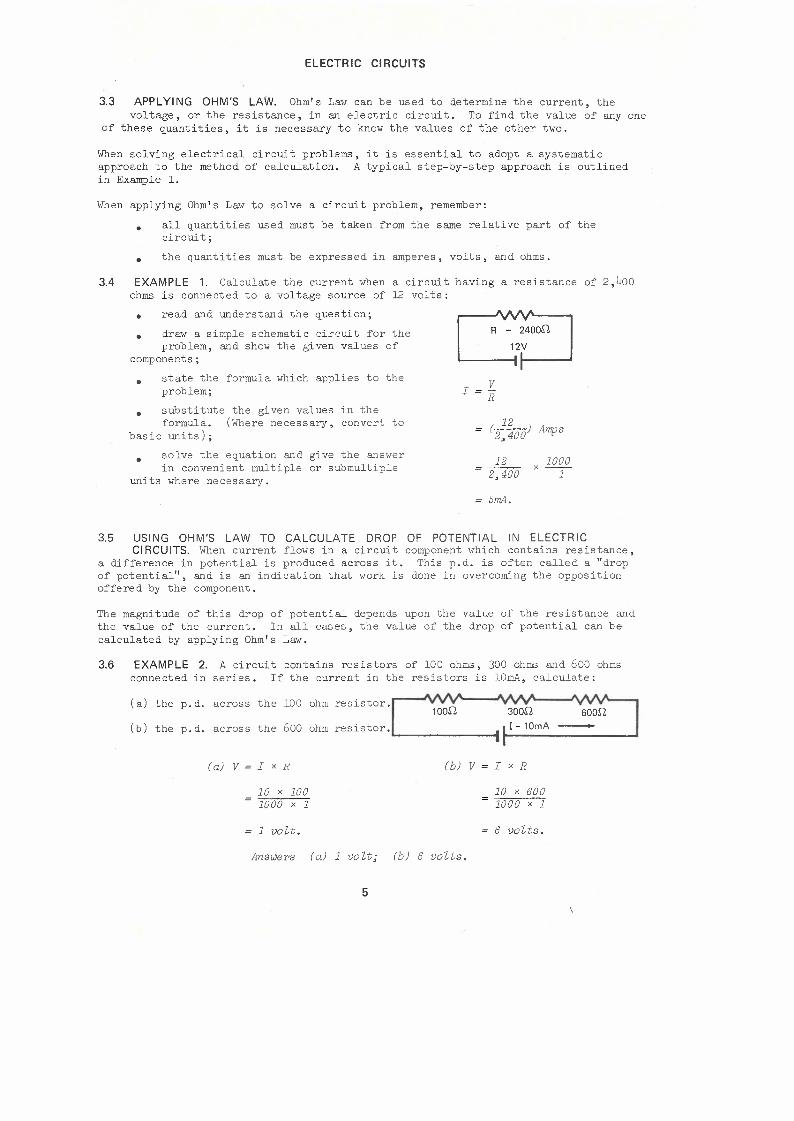
3.3 APPLYING OHM'S LAW. Ohm's Law can be used to determine the current, the voltage, or the resistance, in an electric circuit. To find the value of any one
of these quantities, it is necessary to know the values of the other two.
When solving electrical circuit problems, it is essential to adopt a systematic approach to the method of calculation. A typical step-by-step approach is outlined in Example l.
When applying Ohm's Law to solve a circuit problem, remember:
all quantities used must be taken from the same relative part of the circuit;
•
• the quantities must be expressed in amperes, volts, and ohms,
3.4 EXAMPLE 1. Calculate the current when a circuit having a resistance of 2,400 ohms is connected to a voltage source of 12 volts:
read and understand the question;
draw a simple schematic circuit for the problem, and show the given values of
components;
• •
• state the formula which applies to the problem;
substitute the given values in the formula. (Where necessary, convert to
basic units);
•
solve the equation and give the answer in convenient multiple or submultiple
units where necessary •
•
R = 2400[/,
12V --I
I=l'._ R
12 ( 2 400) Amps ,
12 1000 = 2,400 x--
1
5mA.
3.5 USING OHM'S LAW TO CALCULATE DROP OF POTENTIAL IN ELECTRIC CIRCUITS. When current flows in a circuit component which contains resistance,
a difference in potential is produced across it. This p.d. is often called a "drop of potential", and is an indication that work is done in overcoming the opposition offered by the component.
The magnitude of this drop of potential depends upon the value of the resistance and the value of the current. In all cases, the value of the drop of potential can be calculated by applying Ohm's Law.
3.6 EXAMPLE 2. A circuit contains resistors of 100 ohms, 300 ohms and 600 ohms connected in series. If the current in the resistors is lOmA, calculate:
( a) the p. d.
(b) the p.d.
across
across
the 100 ohm
the 600 ohm
=sistor.~ 1 oon 300n Boon resistor • ._ ,. ~
( a) V = I x R
10 X 100 1000 X 1
1 volt.
(b) V I X R
10 X 600 1000 X 1
6 volts.
Answers (a) 1 volt; (b) 6 volts.
5

ELECTRIC CIRCUITS
While Ohm's Law allows the magnitude of a drop of potential to be calculated, it does not tell us its polarity. The polarity of the difference of potential across a resistor depends upon the direction of the current through it, and is indicated by the use of plus and minus signs.
Fig. 5 shows a simple circuit containing two resistors Rl and R2, connected in series to a battery. The current in the circuit produces the drops of potential Vl and V2 across the resistors. By convention, the current is said to flow from positive to negative in the circuit, so the end at which the current enters each resistor is at a higher positive potential than the end at which it leaves. Therefore, the polarity of Vl is positive at point A with respect to point B, and these points are marked+ and - respectively. The polarity of V2 is determined in the same way, so that point C is positive with res-pect to point D, and these polarities are marked as shown in Fig. 5.
+ V1 + V2
A D
FIG. 5. POLARITY OF DROP OF POTENTIAL.
3.7 USING OHM'S LAW TO CALCULATE RESISTANCE. Ohm's Law can be used to find the resistance of a circuit, or of part of a circuit, when the current and
voltage in the particular part of the circuit are known.
3.8 EXAMPLE 3. A resistor is connected in series with two parallel-connected lamps and a battery. If the current through the resistor is 16OmA, and the p.d.
across it is 4 volts, find the resistance of the resistor.
R=_I:'.. I
4 X 1000 ] X ]60
250,
4. Kl RCHOFF'S LAWS.
4V
+-: ~1.....---..r-½-½
4.1 While Ohm's Law outlines the way in which the three basic q_uantities in the same part of a circuit are related, it does not define the relationship between
q_uantities of the same type in different parts of the circuit. To cover this aspect of circuit behaviour, Ohm's Law was extended by two statements which are now known as Kirchoff' s Laws.
4.2 KIRCHOFF'S FIRST LAW. The first law is sometimes called Kirchoff's Current Law. It states:
The algebraic eum of the currents entering OJ?.d leaving OJ?.y point in a circuit is zero.
This law can be expressed mathematically as:
Il + 12 + 13 + •• " In = 0 where I1 I2 I3
Currents entering or leaving a corronon point in
In a circuit.
6

ELECTRIC CIRCUITS
This expression can be used to find the magnitude and direction of an unknown current which has a common junction with a number of known currents. When applying Kirchoff's Current Law, currents entering a point in a circuit are given a positive sign and those leaving the same point are given a negative sign.
4.3 EXAMPLE 4. The diagram shows the currents at a junction point in a circuit. Find:
(a) the value of the current 14;
(b) the direction of 14 with respect !2 = 7A -
to the junction.
( a) Il + I2 + I3 + I4 = 0 !1 = 10A --+ / I3=5A-
10 + (-7) + (-5) + I4 = 0
-2 + I4 = 0 "'14
I4 = 2 Amps.
(b) As the result is positive, I4 flows towards the junction.
Answers (a) 2 amperes; (b) towards the junction.
4.4 APPLICATION OF KIRCHOFF'S CURRENT LAW TO PARALLEL CIRCUITS. The application of Kirchoff's Current Law to parallel circuits is shown in
Fig. 6. The current (i), arriving at point x is the total current taken from the source. The current leaving point x divides into the branch circuits Il, 12 and 13.
I 13 I
' FIG. 6. APPLICATION OF KIRCHOFF'S FIRST LAW.
According to our convention, the sign of the total current is positive; the signs allotted to the branch currents are negative. Therefore,
I - Il - I2 - I3 = 0
This expression can now be rearranged to show the relationship between the total current and the branch currents in a parallel circuit.
I = Il + I2 + I3.
This statement summarises one of the most important characteristics of parallel circuits.
4.5 Kl RCHOFF'S SECOND LAW. Kirchoff' s second law relates to the voltage distribution in an electric circuit. It is sometimes called Kirchoff' s Voltage
Law.
The law states:
In a closed circuit, the algebraic sum of the applied volta.ge and the potential drops around the circuit is zero.
7
ELECTRIC CIRCUITS
This law can be written mathematically as:
V +VI+ V2 + ... Vn 0 where
V = Applied Voltage
Vl V2 = Potential drops around the Vn circuit.
This expression can be used to find the value of any one of the potential differences in a circuit, provided that the values of the other voltages are known. When applying Kirchoff's Voltage Law, the polarities of the circuit voltages must be taken into account so that they can be added algebraically.
To simplify the algebraic addition of the circuit voltages, a convention is adopted by which the applied voltage is said to be positive while the drops of potential around the circuit are said to be negative.
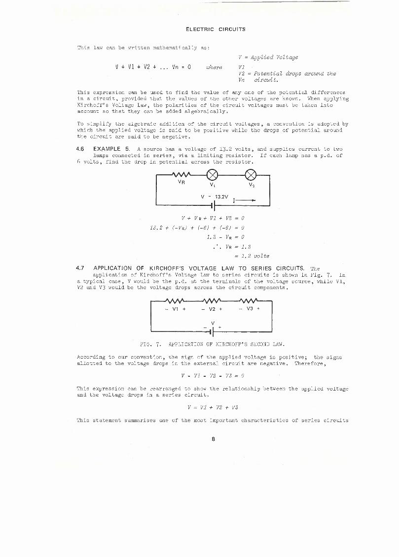
4.6 EXAMPLE 5. A source has a voltage of 13.2 volts, and supplies current to two lamps connected in series, via a limiting resistor. If each lamp has a p.d. of
6 volts, find the drop in potential across the resistor.
V = 13.2V I--
V + V R + Vl + V2 = 0
13.2 + (-VR) + (-6) + (-6) = 0
1.2-VR=O
VR = 1.2
1. 2 volts
4.7 APPLICATION OF KIRCHOFF'S VOLTAGE LAW TO SERIES CIRCUITS. The application of Kirchoff's Voltage Law to series circuits is shown in Fig. 7. In
a typical case, V would be the p.d. at the terminals of the voltage source, while Vl, V2 and V3 would be the voltage drops across the circuit components.
FIG. 7. APPLICATION OF KIRCHOFF'S SECOND LAW.
According to our convention, the sign of the applied voltage is positive; the signs allotted to the voltage drops in the external circuit are negative. Therefore,
V - Vl - V2 - V3 = 0
This expression can be rearranged to show the relationship between the applied voltage and the voltage drops in a series circuit.
V = Vl + V2 + V3
This statement summarises one of the most important characteristics of series circuits
8

ELECTRIC CIRCUITS
5. SERIES CIRCUITS.
5.1 In a series circuit, the current has only one path, and the s ame value of current flows in each component. When current flows in the circuit, a potential
drop is produced across each part of the circuit which contains resistance.
Fig. 8 shows three resistances Rl, R2 and R3 connected in series to a voltage source, V. The current I, produces the potential drops, Vl, V2 and V3.
R1 R2 R3
1---v,-...J i.-·;2 ~ V r-
FIG. 8. SERIES CIRCUIT.
5.2 CURRENT IN SERIES CIRCUITS. As there is only one path for current, the current in Rl is the same as that in R2 and R3. In a series circuit therefore,
the current is the same in all parts.
5.3 VOLTAGES IN SERIES CIRCUITS. The voltages present in a series circuit are the applied voltage, and the potential drops across the individual resistances
in the circuit. Each p.d. represents the part of the potential of the applied voltage which is expended in overcoming the resistance of that part of the circuit.
From Kirchoff's Voltage Law, the sum of the potential drops is e~ual to the applied voltage.
In Fig. 8 therefore:
V Vl + V2 + V3 where
V = Applied p.d. in volts Vl V2 = Circuit p. ds in volts V.3
The value of each of the potential drops in the circuit can be found from Ohm's Law.
That is, Vl = I X Rl
V2 I x R2 where
Vl V2 V.3
I
Circuit p. de in volts
Current in anrperes
V3 =Ix R.3
Rl R2 = Circuit resistances in ohms R.3
5.4 TOTAL RESISTANCE OF SERIES CIRCUITS. As the path for current is through each resistance in turn, the effects of the individual resistances are additive
in limiting the current flow.
In a series circuit therefore, the total resistance is the sum of the individual resistances in the circuit:
In Fig. 8,
Rl + R2 + R3 where RT - Total resistance in ohms Rl R2 = Circuit resistances in ohms R.3
9

ELECTRIC CIRCUITS
5.5 VOLTAGE DISTRIBUTION IN SERIES CIRCUITS. The values of the potential drops around a series circuit are determined by the relative values of current and
resistance. Since the current is the same in all parts, the values of the various p.ds are proportional to the values of resistance across which they are produced.
In Fig. 8, therefore,
V 1 V2 V3 : : Rl R2 R3
This simple relationship offers a convenient method of determining the manner in which the applied voltage is distributed amongst the various p.ds. in the circuit . .Arl example of its application is given in example No. 6.
5.6 EXAMPLE 6. Three. resistors, ru , R2 and R3 of values 100 ohms, 400 ohms and 500 ohms are connected in series to a 10 volt source. Find:
( a) the total resistance of the circuit;
(b) the current;
(c) the pv d , across Rl;
(d) the p.d. across R3.
R1=100.11 R2=400.11 R3=500.11
10V
(a) R = Rl + R2 + R3
100 + 400 + 500
(b) I = .!'.'._ R
100011
10 -- X 1000
1000 -1- lOmA
ALTERNATIVE METHODS
( c) Vl = I x Rl ( c) Vl : V2 : V3 : : Rl R2 R3
10 X 100 And V = Vl + V2 + V3 1000 -1-
IV Rl V Vl = Rl + R2 + R3 X
100 10 = 1V 100 + 400 + 500 X
(d) V3 =Ix R3 R3 (d) VJ= Rl + R2 + R3 X V
10 500 500 10 = 5V = 1000 X -1- = 100 + 400 + t,00 X
= 5V
Answers ( a) lOOO<J; (b) lOmA; (c) 1 V; (d) 5V.
5.7 CHARACTERISTICS OF SERIES CIRCUITS. We can summarise the characteristics of series circuits as follows:
• the current is the same in all parts;
• the applied voltage is the sum of the potential drops around the circuit;
• the total resistance is the sum of the individual resistances in the circuit.
10

ELECTRIC CIRCUITS
Ohm's Law can be applied to a complete series circuit, or to any part of the circuit, provided that the values used are taken from the same part of the circuit.
6. PARALLEL CIRCUITS.
6.1 In a parallel circuit, there are as many current paths as there are branch circuits. The current from the source of voltage divides, and part flows in
each of the branch circuits.
Fig. 9 shows three resistances Rl, R2 and R3 connected in parallel to a source, V. The total current I, divides into the branch circuits Il, I2, and I3, according to the branch conductances Gl, G2 and G3.
V
.. R1 R2
I2
R3
FIG. 9. PARALLEL CIRCUIT.
6.2 VOLTAGE IN PARALLEL CIRCUITS. As all the branch circuits are connected to the same point, the p. d. across Rl is the same as that across R2 and across R3.
In a parallel circuit, therefore, the p.d. is the same acros~ each parallel branch.
In simple circuits such as Fig. 9, the p.d. across each branch is also equal to the voltage of the source.
6.3 CURRENTS IN PARALLEL CIRCUITS. The total current divides so that part flows in each of the branch circuits. After passing through the branch
circuits, the branch currents recombine to return to the source.
From Kirchoff's Current Law, the sum of the branch currents equals the total current.
In Fig. 9, therefore:
= 11 + 12 + 13 where
I = Total current in amperes
I1 I2 n
Branch currents in amperes
The value of each of the branch currents can be found from Ohm's Law.
That is,
V I1 Il = RT I2 = Branch currents in amperes
I3
V where = App lied p. d. in vo Us 12 = R2 V
13 = ~3 Rl R2 = Branch resistances in ohms R3
11

ELECTRIC CIRCUITS
6.4 TOTAL CONDUCTANCE OF A PARALLEL CIRCUIT. The conductance of a circuit is a measure of the ease with which it conducts electric current. When a circuit
contains a number of parallel branches, the total conductance is greater than that of any of the brancheg congidered singly. Each time an additional current path is connected in parallel, the total conductance increases by an amount equal to the conductance of the new branch. The total conductance is therefore equal to the sum of the branch conductances.
In Fig. 9, GT = Total conductance in siemens
Gl + G2 + G3 where G1 G2 G3
Branch conductances in siemens
6.5 CURRENT DIVISION IN PARALLEL CIRCUITS. The values of the currents flowing in the branch circuits are determined by the relative values of potential
difference and branch resistance. Since the same p.d. exists across all parallel branches, the values of the branch currents are inversely proportional to the resistance values of the various branches.
In Fig. 9, therefore,
Il I2 I3 1 . 1 . 1 RT · R2 • R3
Alternatively, this relationship can be written as:
Il I2 I3 Gl G2 G3
This means that when the branches of a parallel circuit contain equal resistance, the total current divides equally between them. When the resistances of the branch circuits are not equal, the total current divides llilequally, with the greatest part flowing in the branch circuit which has the least resistance (or greatest conductance).
6.6 TOTAL RESISTANCE OF PARALLEL CIRCUITS. The total or equivalent resistance of a parallel circuit or parallel group of resistances, is that single value of
resistance, which when connected in place of the circuit or group, has the same resistance.
The basic method of determining the total resistance of a parallel circuit is as follows:
• • •
calculate the current in each branch circuit;
add the branch currents to find the total current;
using the total current and the applied voltage, calculate the total resistance by applying Ohm's Law.
This method can be applied to all parallel circuits, irrespective of the number of branches or the type of current flowing.
6.7 EXAMPLE 7. In the adjacent circuit, find:
20V l R1 (a) the total current; - son (b) the total resistance.
I1 = £_ = 20 x 1000 = 250mA R1 80
R1 200.11
R3 400.11
12

ELECTRIC CIRCUITS
I2 = .!'.'._ = §2._ x 1000 R2 200
I3 = .!'.'._ = §2._ X 1000 R3 400
(a) I= Il + I2 + I3
= 250 + 100 + 50
(b) R = y
lO0mA
50mA
400mA
Answers (a) 400mA; (b) 50~.
6.8 TOTAL RESISTANCE FORMULA. There is an alternative and more direct method of finding the total resistance of a parallel circuit. This method is based on
the conductance values of the branches, and can be applied directly to a network of resistors such as that shown in Fig. 10.
FIG. 10. PARALLEL RESISTORS.
In Fig. 10, GT
But GT
Gl + G2 + G3
1 1 1 Rl + R2 + R3
1 RT
6.9 TOTAL RESISTANCE OF TWO PARALLEL RESISTANCES. When the circuit contains only two parallel paths, the basic formula for total resistance can be
resolved further.
1 -= RT 1 1 -+ - Rl R2
R2 + Rl Rl x R2
Rl x R2 RT= Rl + R2
It must always be remembered that this method, often called the "product over the sum" method, is restricted to circuits containing two resistances only.
13

ELECTRIC CIRCUITS
6.10 TOTAL RESISTANCE OF EQUAL PARALLEL RESISTANCES. ~Then two resistances of the same value are connected in parallel, the current is the same value in each
resistance. The total current is therefore double that which would flow if the circuit contained only one branch, so that the total resistance is half the value of one of the resistances.
From this we can formulate a general rule from which the total resistance of a parallel arrangement of eQual value resistances can be found.
RT= Total resistance in ohms R n where R
n Resistance of one branch in ohms
Number of branches having equal resistance
In all cases, where resistances are connected in parallel, the connection of an additional parallel resistor provides another path for current and reduces the total resistance. Therefore the total resistance of a parallel resistance network must always be less than the smallest value of resistance in the network.
6.11 CHARACTERISTICS OF PARALLEL CIRCUITS. The characteristics of a parallel circuit can be summarised as follows:
• • •
the p.d. is the same across each parallel branch;
the total current is the sum of the branch currents;
the total conductance is the sum of the branch conductances.
Ohm's Law can be applied to parallel circuits, either to the complete circuit or to any part, provided that the values used are taken from the same part of the circuit.
7. SERIES-PARALLEL CIRCUITS.
7.1 Series-parallel circuits are formed when three or more resistors are connected in a complex circuit, part series and part parallel. There are two basic
arrangements:
•
•
when a resistance is connected in series with a parallel combination, (Fig. lla);
when one or more parallel branches contain r-e s i.s t an ce s in series. (Fig. llb).
R1 R2
R3 R1 R2
R3
(a) (b)
FIG. 11. TWO WAYS TO CONNECT RESISTANCES IN SERIES-PARALLEL.
7.2 CHARACTERISTICS OF SERIES-PARALLEL CIRCUITS. Series-parallel circuits have no special characteristics of their own, and no new rules or formulas relate
specifically to these circuits. However the rules relating to series circuits still apply to those components connected in series, and the rules relating to parallel circuits similarly apply to those components connected in parallel.
14

ELECTRIC CIRCUITS
These rules are summarised as follows:
• the same current flows through each resistance in a series group;
• the current flowing into a parallel group of components equals the sum of the individual branch currents in the group;
• the same voltage exists across each branch of a parallel group;
• the sum of the voltages around the circuit equals the applied voltage.
7.3 EXAMPLE 8. In the series-parallel circuit shown below, calculate ....--J\A.Af\-.----...,
( a) the total resistance;
(b) the circuit current;
(c) the p.d. across Rl. 25V
R2 and R3 in p aral.Lel:
(a) Total Resistance
(b) Circuit Current
R2 x R3 R2 + R3
100 X 300 100 + 300
Rl + 750
50 + 75
V R
25 1000 = 125 X -1-
750
1250
200mA
(c) P.D. across Rl IX Rl
_ 200 50 - 1000 x 1 = lOV
Answers ( a) 1250; (b) 200mA; ( c) 10 V.
8. USING RESISTORS TO CONTROL CURRENT AND VOLTAGE.
8.1 To vary the current in a circuit, or to change the p.d. across an item of equipment, either the applied voltage or the resistance must be altered. In
practice, altering the resistance is generally the simplest way available, and often additional resistors are included in the circuit for control purposes. These resistors can be of the fixed value or variable type, and they can be connected in series or in parallel with the circuits they control.
8.2 USE OF A FIXED RESISTOR IN SERIES. A resistor can be connected in series with a circuit when it is desired to limit the current to a certain value, or
when it is required to reduce the p.d. across one of the circuit components. Often, a resistor is connected in series with a component to allow the component to operate from a circuit voltage source higher than its voltage rating.
Fig. 12 shows an application of this method. It is desired to operate a small switch-board lamp from a 50 volt battery. The lamp is rated at 6 volts and operates normally with a current of 40mA. The series resistor used must therefore produce a p.d. of 44 volts when the current is 40mA.
15

ELECTRIC CIRCUITS
V Value of R = y
R 40mA --
SOY
44 = - X 40 1000 -1-
11000,
FIG. 12. USING A SERIES RESISTOR TO CONTROL VOLTAGE.
8.3 USE OF A FIXED RESISTOR IN PARALLEL. There are occasions when it is necessary to connect in series, two items which have different current
requirements. In these cases, a resistor can be connected in parallel with the low current item, so that the total current of this combination equals the operating current of the other item of equipment.
Fig. 13 shows how two 6 volt lamps, LPl and LP2, with operating currents of 6OmA and 4OmA respectively, are operated from a 12 volt battery. The value of the parallel resistor is chosen so that with a p s d; of 6 volts, its current is equal to the difference between the lamp currents.
Current in R = 20mA 6V
60mA-LPl Value of R V I
6 = 20
1000 x-- 1
3000,
FIG. 13. USING A PARALLEL RESISTOR TO CONTROL CURRENT.
8.4 USE OF A VARIABLE RESISTOR AS A RHEOSTAT. A variable resistor connected in series with a piece of equipment for the purpose of controlling the
current is usually called a rheostat.
An example of the use of a rheostat is shown in the simple lamp dimming circuit of Fig. 14. When the rheostat is set for maximum resistance (Fig. 14a) the value of the current is reduced and the lamp is dimmed. When the rheostat is set for minimum resistance, (Fig. 14b) the lamp glows normally.
6V • I I 6V
(a) Lamp Dimmed. (b) Lamp Normal.
FIG. 14. USING A RHEOSTAT TO CONTROL CURRENT.
8.5 USE OF A VARIABLE RESISTOR AS A POTENTIOMETER. A variable resistor connected to a voltage source for the purpose of deriving a variable output
voltage is usually called a potentiometer.
16

ELECTRIC CIRCUITS
The usual method of connecting a potentiometer in a circuit is shown in Fig. 15. The input voltage is connected directly across the resistance element; the variable output voltage is available between the wiper arm and one end of the resistance element.
INPUT VOLTAGE
OUTPUT VOLTAGE
FIG. 15. USING A POTENTIOMETER TO CONTROL VOLTAGE.
When the potentiometer is set so that the wiper arm is contactipg the upper end of the resistance element, the output voltage is eg_ual to the input voltage. When the potentiometer is set to the other extreme, the output vo.Lt age is zero. Intermediate settings of the wiper arm give intermediate values of output voltage. The connections to the potentiometer are usually made in such a way that the output voltage is increased when the potentiometer control knob is turned in a clockwise direction.
S.6 VOLTAGE DIVIDERS. A voltage divider is similar to a potentiometer in that it is used to control voltage. However, where the potentiometer provides a
continuously variable output voltage, the voltage available from a voltage divider is fixed.
Fig. 16a shows a voltage divider connected across a 100 volt battery. The voltage divider connections are adjusted to tap off various voltages between zero and 100 volts. With no load connected, the potential at point B, one g_uarter of the way along the resistance element, is 25 volts negative with respect to point A. Point C, half way along the voltage divider is 50 volts negative to point A.
- lOOV E D - 75V
100V I ~c - - SOY
INPUT VOLTAGE
B - - 25V
Rl
R2 OUTPUT VOLTAGES
A + R3
( a) Voltage Divider. (b) Voltage Divider using Resistors.
FIG. 16. USING A VOLTAGE DIVIDER TO CONTROL VOLTAGE.
Many voltage dividers use a specially constructed wire wound resistor which has adjustable tapping points to allow precise adjustment of the tapped off voltage. An alternative arrangement using a network of fixed resistors is shown in Fig. 16b. With this type of voltage divider the output voltage is determined by the relative values of the resistors and is not adjustable.
17

ELECTRIC CIRCUITS
It is important to realise that the output voltage from a voltage divider or potentiometer depends to a large extent upon the current taken from the output terminals. In Fig. 16a, if a load circuit such as a small 50 volt lamp is connected at the 50 volt tapping point (between A and c), the lamp current flows via the upper half of the resistance element, but not in the lower section. This means that the p.d. from E to C is greater than that from C to A, and the p.d. across the lamp is less than 50 volts. When a circuit with a varying resistance is connected instead 01 the lamp, the current flowing in the upper section of the voltage divider constantly changes in value, and consequently, the output voltage varies.
This effect can be reduced by choosing the resistance value of the voltage divider so that the value of the "bleed" current, that is, the current flowing in the voltage divider itself, is several times greater than the current taken by the load circuit.
9. POWER AND ENERGY IN ELECTRIC CIRCUITS.
9.1 The operation of electrical equipment depends upon the conversion of energy from one form to another. In an electric torch, for example, the chemical energy of
the battery is converted into electrical energy, which is in turn converted into light and heat energy. The rate at which energy transformation takes place is described in terms of the power of the circuit.
9.2 POWER. Power is defined as the rate of doing work. In a mechanical application, power is found by dividing the total work performed by the time taken. In this
way, the horse-power (equal to 33,000 foot-pounds per minute), is derived,
In an electric circuit, power similarly depends upon relative values of work and time. However, work and time are not quantities which are usually measured in an electric circuit. To determine the power therefore, it is necessary to express work and time in terms of basic circuit quantities such as current and voltage.
We have seen that:
Voltage Work Charge and Current Charge
Time
Transposing these expressions,
Work Voltage x Charge and Time Charge Current
Therefore,
Power Work Time
Voltage x Charge x Current Charge
= Voltage x Current.
9.3 UNIT OF ELECTRIC POWER. The unit used to measure electric power is the WATT, the abbreviation for which is W. The power in a circuit is one watt when
a current of one ampere is produced by an applied voltage of one volt. Also a circuit component transforms energy at the rate of one watt when a current of one ampere produces a potential drop of one volt across its terminals.
18

ELECTRIC CIRCUITS
This relationship is expressed by the formula:
P = PoweP in watts
P = V x I where V = Potential difference in volts
I = Current: in amperes
Where large powers are involved, multiple units are used. These are:
• the kilowatt (abbreviated kW), lkW = lW x 103;
• the megawatt (abbreviated MW), lMW = lW x 106•
In telecom, the powers are often much less than a watt, and submultiple units are used. These are:
• •
the milliwatt ( abbreviated mW), lmW
the microwatt (abbreviated µW), lµW
lW x 10-3;
lW x 10-6.
In some alternating current circuits, the product of the current and the applied voltage is expressed in Volt-Amps rather than in watts. The term volt-amp (abbreviated V.A.) is used because some circuit components are capable of storing energy so that the rate of energy dissipation is less than that indicated by the product of voltage and current. This aspect of circuit behaviour is fully explained in other publications.
9.4 POWER FORMULAS. The basic expression for power can be rearranged to give alternate formulas which are extremely useful in determining the power in a
particular circuit component. These formulas are derived as follows:
The basic expression for power is:
Power V X I
According to Ohm's Law,
V = I X R and I V R
Substituting in the basic expression,
p = (I X R) X I and p V X (.::{_) R
Therefore,
p or P = v2 R
The three power formulas apply to all D.C. circuits, either to the whole circuit or to any part. When the formulas are being applied, however, the values used must be taken from the same part of the circuit.
9.5 POWER IN SERIES AND PARALLEL CIRCUITS. The power in any component in any type of circuit, that is, series, parallel, or series-parallel, can be
determined by application of the appropriate formula. The values used however, must be taken from the particular part of the circuit under consideration.
19

ELECTRIC CIRCUITS
In all cases, the total power is equal to the sllill of the individual powers in the circuit. This relationship can be expressed as:
Pr Pl + P2 + P3 where FT = Total power> in tJatts Pl P2 P:3
Circuit powers in watts
9.6 POWl;R RATING OF ELECTRICAL APPARATUS. Most items of electrical apparatus are given a power rating. The power rating in watts indicates the rate
at which the device converts electrical energy into energy of another form.
In some cases, the power rating indicates the actual power of the device when it is operated under specified conditions. For example, a 240 volt, 100 watt lamp transforms electrical energy into light and heat at the rate of 100 watts when it is connected to a 240 volt supply.
In other instances, the power rating indicates the maximllill power that the device is designed to dissipate. When the device is operating normally, the power may be much less than the rated value. The method of rating resistors is an example of this type of power rating. For example, a 100 ohm, 1 watt resistor is physically larger than a 100 ohm,½ watt resistor of similar composition, so that it can allow electrical energy to be transformed into heat at a greater rate than in the smaller resistor. Where this method of rating is used, the device is not normally given a voltage or current rating, and it can be operated with any combination of current and voltage, as long as their product does not exceed the power rating.
9.7 RELATIONSHIP BETWEEN ELECTRICAL AND MECHANICAL POWER. It is accepted practice to rate the power of some types of electrical equipment, mainly motors,
in terms of the mechanical horsepower they develop.
For practical purposes, the conversion from electrical to mechanical power is given by the following relationship:
1 HORSEPOWER 750 WATTS.
9.8 ELECTRIC ENERGY. Energy is the capacity for doing work. The energy of a mechanical device or electric circuit is equal to the total amount of work
performed, and is found from the product of the rate of doing work and the time taken.
Therefore:
ENERGY POWER x TI ME.
The unit used to measure kinetic, potential, chemical, electrical, and all other forms of energy is the JOULE. One joule (J) is the amount of energy expended in one second by a circuit with a power of one watt.
The joule is inconveniently small, and in practice larger units are used to measure electrical energy. These are:
• the watt-hour (abbreviated Wh) which equals 3,600 watt-seconds (3.6kJ);
• the kilowatt-hour (abbreviated kWh) which equals 1000 watt-hours (3.6MJ).
In terms of these units, the energy used by a 240 volt, 100 watt lamp is:
• • • •
100 joules in one second;
6000 joules in one minute;
100 watt-hours in one hour;
2 kilowatt-hours in 20 hours.
20

ELECTRIC CIRCUITS
The kilowatt-hour is the unit of energy used in the sale of electricity for domestic and industrial use, and electricity supply meters (kilowatt-hour meters) show the consumption of electrical energy in terms of this unit.
9.9 HEATING EFFECT OF ELECTRIC CURRENT. Electrical energy is converted into heat whenever current flows through resistance. Some items of equipment are
expressly intended to utilise the heating effect of electric current. In others, the production of heat is an unavoidable side-effect, and constitutes an energy loss.
Early scientific studies supposed heat to be some form of intangible fluid called "caloric". The unit defining the amount of caloric was called the calorie, which is defined as the quantity of heat required to raise the temperature of one gramme of water by 1°c .
Although traditionally given in units of calories, heat is really a form of energy, for which the unit of quantity is the joule. By experiment, an English brewer named Joule demonstrated that heat is a manifestation of mechanical work, and was the first to measure the magnitude of the conversion factor needed to relate the "heat unit" to the energy unit.
This relationship is expressed as:
• •
1 calorie
1 joule
4.2 joules;
0.24 calorie.
The quantity of heat produced in an electrical circuit is the product of the circuit power and the period of time the power is applied. This relationship is generally expressed in terms of current and resistance, as these are the quantities most directly associated with the production of heat. However, any of the expressions for electrical power can be used in the formula, with identical results.
The heating effect of an electric current in a conductor can be found from:
Q where Q I R t
Quantity of heat in joules Current in amperes Resistance in ohms Time in seconds
9.10 EFFICIENCY OF ELECTRICAL APPARATUS. In general, the efficiency of a device used for converting one form of energy to another is determined by the
ratio of the energy output in the desired form from the device, to the energy input to effect the conversion.
Efficiency is usually represented as a percentage, and can be found from the following expression:
PERCENTAGE EFFICIENCY
10. ELECTRIC SUPPLY SOURCES.
ENERGY OUTPUT x 100 •..•• ,,-n, ,...,, T r.r •..•• I,..,..
10.1 The preceding topics in this publication have concentrated attention on that part of the electric circuit which is external to the source of supply. In
most cases, it has been assumed that the circuit is energised from a battery or similar device which is capable of supplying the current requirements of the load.
21

ELECTRIC CIRCUITS
While some items of telecom equipment operate from such a battery, many others operate with input voltages derived from telephone lines, radio receiving antennae and other low-power sources which have electrical characteristics vastly different from those of high-power sources such as large battery installations and motor-driven generators. In all cases, the supply source has certain electrical characteristics and these must be taken into account when considering the operation of the circuit as a whole.
10.2 TYPES OF SUPPLY SOURCES. From the viewpoint of explaining the operation of electrical equipment, there are two "ideal" types of supply sources. These are:
•
•
THE CONSTANT VOLTAGE SOURCE, in which the output voltage remains constant when the resistance of the load circuit varies.
THE CONSTANT CURRENT SOURCE, in which the output current remains constant, independent of variations in the resistance of the load circuit.
Both of these supplies have their particular applications in telecommunications, examples of which will be found in other publications.
10.3 CONSTANT VOLTAGE CHARACTERISTICS. Fig. 17 shows the electrical characteristics of an ideal constant voltage source. The variation of output
current with change of load resistance is shown in Fig. 17a, which shows that as the load resistance increases, the output current decreases, but the output voltage remains constant.
In many applications, it is desirable to show the effect that variation of output current has on the output voltage. Fig. 17b shows the previous characteristic drawn in this form.
E
OUTPUT VOLTAGE
AND CURRENT
', ', I ', .•....... ......... -=
LOAD RESISTANCE (a)
OUTPUT CURRENT (b)
FIG. 17. IDEAL CONSTANT VOLTAGE SOURCE CHARACTERISTICS.
10.4 CONSTANT CURRENT CHARACTERISTICS. Fig. 18 shows the characteristics of an ideal constant current source. As the load resistance is increased, the current
remains the same but the output voltage increases. This is shown in Fig. 18a, while Fig. 18b shows the same characteristic in which output voltage is drawn as a function of output current.
OUTPUT VOLTAGE
AND CURRENT
I .•.•.. ...... _,,,,.,.,,,.
E .,,,..-' .,,,.,, ....• .•.• ~,.,.
OUTPUT VOLTAGE
LOAD RESISTANCE
(a)
OUTPUT CURRENT
(b)
FIG. 18. IDEAL CONSTANT CURRENT CHARACTERISTICS.
22
ELECTRIC CIRCUITS
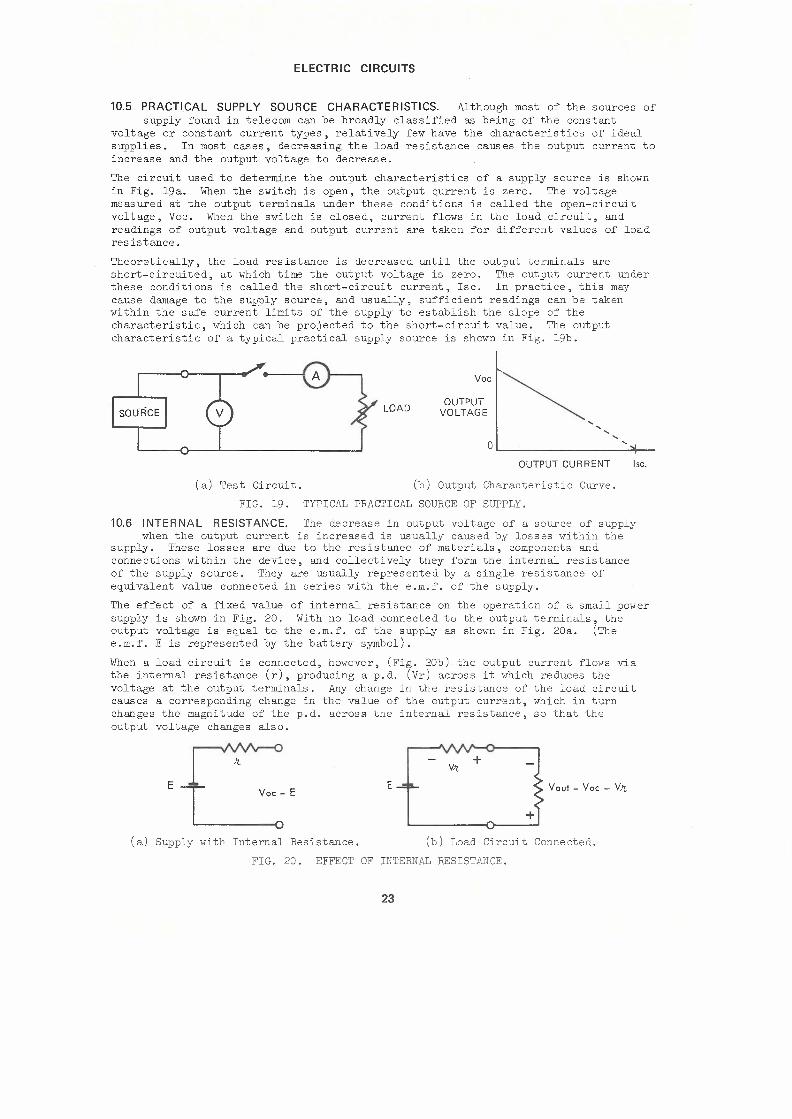
10.5 PRACTICAL SUPPLY SOURCE CHARACTERISTICS. Although most of the sources of supply found in telecom can be broadly classified as being of the constant
voltage or constant current types, relatively few have the characteristics of ideal supplies. In most cases, decreasing the load resistance causes the output current to increase and the output voltage to decrease.
The circuit used to determine the output characteristics of a supply source is shown in Fig. 19a. When the switch is open, the output current is zero. The voltage measured at the output terminals under these conditions is called the open-circuit voltage, Voc. When the switch is closed, current flows in the load circuit, and readings of output voltage and output current are taken for different values of load resistance.
Theoretically, the load resistance is decreased until the output terminals are short-circuited, at which time the output voltage is zero. The output current under these conditions is called the short-circuit current, Isc. In practice, this may cause damage to the supply source, and usually, sufficient readings can be taken within the safe current limits of the supply to establish the slope of the characteristic, which can be projected to the short-circuit value. The output characteristic of a typical practical supply source is shown in Fig. 19b.
LOAD
Voc
OUTPUT VOLTAGE
0 '
OUTPUT CURRENT lsc.
(a) Test Circuit. (b) Output Characteristic Curve.
FIG. 19. TYPICAL PRACTICAL SOURCE OF SUPPLY.
10.6 INTERNAL RESISTANCE. The decrease in output voltage of a source of supply when the output current is increased is usually caused by losses within the
supply. These losses are due to the resistance of materials, components and connections within the device, and collectively they form the internal resistance of the supply source. They are usually represented by a single resistance of eg_ui valent value connected in series with the e.m.f. of the supply.
The effect of a fixed value of internal resistance on the operation of a small power supply is shown in Fig. 20. With no load connected to the output terminals, the output voltage is eg_ual to the e.m.f. of the supply as shown in Fig. 20a. (The e.m.f. Eis represented by the battery symbol).
When a load circuit is connected, however, (Fig. 20b) the output current flows via the internal resistance (r), producing a p.d. (Vr) across it which reduces the voltage at the output terminals. Any change in the resistance of the load circuit causes a corresponding change in the value of the output current, which in turn changes the magnitude of the p.d. across the internal resistance, so that the output voltage changes also.
E~ T Voc= E
'--------o (a) Supply with Internal Resistance.
E
Y!t + You!= Voc - V1t
(b) Load Circuit Connected.
FIG. 20. EFFECT OF INTERNAL RESISTANCE.
23

ELECTRIC CIRCUITS
In addition to its effect on output voltage, internal resistance also limits the maximum value of current that a source can deliver. To a large extent, therefore, the internal reoiotance of a oource determine~ the type of load circuit it i~ capable of supplying, and sources can be classified according to the value of their internal resistance in relation to the resistance of the intended load circui. t.
10.7 CONSTANT VOLTAGE SOURCES. When the internal resistance of a source is much lower than that of its load circui.t, the source behaves as a constant voltage
source.
Fig. 21 shows a generator with an open-circui.t voltage of 10 volts and an internal resistance of 100 ohms connected to a load circui.t which can vary in resistance from 2,000 to 4,000 ohms. The output characteristics of the generator are shown in the accompanying table. (The term "generator", as used above, implies any device capable of producing a difference of potential across its· terminals.)
2kn to 4kn
LOAD RESISTANCE (Q) 2000 3000 4000
Output Current (mA) 4,76 3.23 2.44
Output Voltage (V) 9,52 9.69 9.76
FIG. 21. CONSTANT VOLTAGE SOURCE.
The table shows that although the output current is reduced to about half its original value as the load resistance increases, the output voltage remains substantially constant. This is because the changes in current cause only relatively small changes of p.d. across the internal resistance and so the output voltage is not greatly affected. It emphasises the importance of the internal resistance of the source being much less than the load resistance.
Practical constant voltage sources include generators and batteries which have internal resistance of much less than an ohm, and which supply currents of up to hundreds of amperes, as well as oscillators and signal generators which have internal resistances of hundreds of ohms, delivering currents of the order of a few milliamperes.
10.8 CONSTANT CURRENT SOURCES. When the internal resistance of a source is many times greater than the resistance of the load circuit it supplies, the source
behaves as a constant current source. The generator shown in Fig. 22 comes into this category.
As in the previous example, the open-circui.t voltage is 10 volts, and the load resistance can vary in value from 2,000 ohms to 4,000 ohms. The difference lies in the internal resistance, which in this case is 50,000 ohms. The output characteristics of the generator are shown in the table.
2kQ to
4kQ
LOAD RESISTANCE (Q) 2000 3000 4000
Output Current (mA) 0.192 0.189 0.185
Output Voltage (V) 0.31:i 0,57 0.74
FIG. 22. CONSTANT CURRENT SOURCE.
24

ELECTRIC CIRCUITS
In this instance, it is the output current which remains substantially constant, even though the output voltage almost doubles in value over the range of load resistance. It is interesting to note that even when the load resistance is reduced to zero ohms, that is, when the output terminals are short circuited, the output current rises to only 0.2mA.
Examples of constant current sources include some types of microphones and radio receiving antennae, Under certain circumstances, some types of electron tubes and transistors also behave as constant current devices.
11. INTRODUCTION TO EQUIVALENT CIRCUITS.
11.1 The understanding of the operation of an item of equipment can sometimes be complicated by the complexity of the device which acts as its source of supply.
On these occasions the operation of the load circuit can often be better appreciated when the circuit of the source is simplified to an equivalent connection which has the same characteristics.
11.2 EQUIVALENT CIRCUITS. An equivalent circuit is one which is electrically equivalent to another, and therefore can be substituted for it.
200
55V 100 300, 210
FIG. 23. CIRCUIT OF POWER SUPPLY WITH 210~ LOAD.
Fig. 23 shows the circuit of a small power supply which delivers lOOmA into a load circuit having a resistance of 210 ohms, Fig. 24a shows a simpler circuit, which, when connected to a 210 ohm load, delivers the same value of current. It has a constant voltage source of 33 volts in series with an internal resistance of 120 ohms. As far as the load circuit is concerned, the simpler crrcuit, although it has different values of internal resistance and e.m.f., is equivalent to the actual circuit, and could be substituted for it for all values of load resistance. This can be verified by calculations.
120
275mA CONSTANT VOLTAGE
100mA - 210 CONSTANT
CURRENT 120 210
(a) Constant Voltage Equivalent. (b) Constant Current Equivalent.
FIG. 24. TYPES OF EQUIVALENT CIRCUITS.
The constant voltage source in Fig. 24a is only one type of equivalent circuit. Another equivalent of the same circuit could be obtained using a constant current source. This is shown in Fig. 24b.
25

ELECTRIC CIRCUITS
This circuit can also be verified by calculations to be the electrical equivalent of Fig. 23 and therefore also of Fig. 24a for all values of load connected to it. It should be noted that where calculations are made in a circuit containing a constant current source, the value of cu~~ent given must be used as the output current of the constant current generator for all load conditions. The output voltage will vary depending upon the value of the load.
11.3 The two preceding examples show that a simpler equivalent circuit can be used to determine the behaviour of a circuit which has a complex supply source. The
circuit function will determine whether the equivalent circuit used is to have a constant voltage or a constant current basis. These simplifications are applied to circuits which use transistors or electron tubes, where the "complex" arrangement of the circuit being studied can be reduced to a circuit similar to Figs. 24a or 24b. An example of this is shown in Fig. 25.
H11
6V ~ - R1
J c,
! CONSTANT~ RL
o-1 crJ t RL CURRENT
I (3
(a) Amplifier Circuit. (b) Output Circuit Equivalent.
FIG. 25. SINGLE-STAGE AMPLIFIER.
Fig. 25a is the circuit of a single-stage amplifier, and Fig. 25b is a simplified equivalent for the output circuit of the amplifier. The equivalent circuit can be used to calculate the signal current in the load. The output section of the circuit is represented as a constant current source which has an internal impedance R. This represents the output impedance of the amplifier. RL represents the external load to which the output signal of the amplifier is applied, and in which the useful power is dissipated. Methods of calculating the values of Rand I are beyond the scope of this paper, but are covered in other Technical Training Publications.
12. MAXIMUM POWER TRANSFER.
12.1 When a source is required to supply its highest possible output voltage, the load resistance should be as high as possible with respect to the resistance of the
source. When the maximum value of output current is required, the value of the load resistance must be as low as possible. In telecom, however, we are often more concerned with the transfer of power from a source to its load. As power is proportional to the product of E and I, the conditions for maximum power in the load are in opposition, and a compromise is necessary.
The necessary conditions for maximum power transfer are defined in what is known as the Maximum Power Transfer theorem. This theorem states, in effect, that for a given source with a fixed value of internal resistance, maximum power is transferred to the load circuit when the resistance of the load is equal to the internal resistance of the source.
26

ELECTRIC CIRCUITS
12.2 MAXIMUM POWER TRANSFER. Fig. 26 shows a generator, having an open-circuit voltage of 10 volts and an internal resistance of 300 oh=, connected to a load
circuit which can be varied in resistance from 100 ohms to 2000 ohms. The values of output current, voltage and power for each chosen value of load resistance are listed in the table •
100n to
Voc=10V 2kr2
LJOAD RESISTANCE (D) 100 200 300 400 600 1000 2000
Output Current (mA) 25 20 16. 7 14.3 11.1 7.7 4.3
Output Voltage (V) 2.5 4 5 5.7 6.7 7.7 8.6
Output Power (mW) 62.5 80 83.5 81.5 74.4 59.3 37
FIG. 26. MAXIMUM POWER TRANSFER.
These values are used to draw the graph, (Fig. 27) which shows that as the resistance of the load is progressively increased, the current decreases and mA the output voltage increases. The output power however, attains a peak value when the resistance of the load is 300 ohms, which is the same value as the internal resistance of the source. At this mW point the load is said to be "matched" to the source.
Although the power transfer between source and load is at a maximum value when the resistance of the Volts load eQuals the internal resistance of the source, the efficiency of the circuit under these conditions is only 50%, as there is as much energy dissipated in the internal resistance of the source as there is 100 in the load. However, matching bestows other advantages, and in telecom eQuipment special procedures are often adopted to ensure that this condition is achieved. FIG. 27.
Volts
mW
mA
300
LOAD RESISTANCE
2000
MAXIMUM POWER TRANSFER.
27

ELECTRIC CIRCUITS
13. TEST QUESTIONS.
1. What is meant by the fotlowin,g terms? ( a) closed circuit; (c) short circuit;
(b) open circuit; ( d) earth circuit.
2. Dr(J}J) simple circuit diagrams containing a battery and two lamps, with the Zamps connected (a) in series, and (b) in parallel.
J. State Ohm's LCJ}J), and quote the mathematical expression of this l(J}J).
4. State Kirahoff's First and Second Laws.
5. What are the three basia aharaateristics of series circuits?
6. Find the total resistance of a network containing three paralleled resistors, having values of 40Q, lOOQ and 200Q.
?. What are the three basic characteristics of parallel circuits?
8. Dr(J}J) simple circuit diagrams, each containing three resistors and a battery to show the two basic ne thode of series-parallel connection.
9. By means of a simple circuit diagram, show how a 12 volt lamp which normally operates with a current of 50mA, can be operated from a 50 volt battery.
10. Dr(J}J) a simple circuit diagram to show how two 6 volt lampe , with operating currents of 50mA and ?5mA respectively, can be operated from a 12 volt battery.
11. What is a rheostat?
12. Dr(J}J) a simple circuit diagram showing how a variable voltage can be derived from a fixed voltage source by rreans of a potentiometer.
13. Define the term "power", as applied to electric circuits.
14. Name the basic unit used to measure power in electric circuits. Name two other units, equal to one thousand times and one thousandth of the basia unit respeatively.
15. Calculate the power in a lOOQ resistor whiah has a p.d. of 5 volts across its terminals.
16. Express in calories the amount of heat generated when a current of 10 amperes flows for 8 hours in a 21 ohm heater.
17. What is meant by (a) a aonstant voltage source, and (b) a aonstant current source? Dr(J}J) simple graphs to shOliJ the output characteristics of eaah type of source.
18. What effect does the internal reei.etonoe of a sourae have on its output voltage when a load is aonnected to the sourae?
END OF PAPER
28