
Electric chain hoists
31
Electric chain hoists Moving on up. crane systems ABUCompact • Product information • Technical data
Transcript of Electric chain hoists

Ele
ctr
ic c
hain
hois
ts
Moving on up.crane systems
ABUCompact• Product information• Technical data

Dimensioned sketchesABUCompact GMC, GM2 – GM6
Please fold page out

3/4/5
Dimensioned sketches of chain hoists
ABUCompact GMC and GM2 to GM6
stationary
with EF electric trolley
with additional housing
with HF push trolley

Standard equipment
The new generation of ABUCompact chain hoists fea-ture a fresh new design and convincing technical solu-tions. The 3 phase 400 volt hoists units are available infour different sizes to reliably handle loads from 80 kgthrough 4000 kg. The motor and the gear unit are ofmodular design, allowing us to produce a wide varietyof versions for lifting speeds up to 20 m/min and FEMgroups up to 4m at attractive prices.
The GM2, GM4 and GM8 hoists have already been introduced. The series will be completed by the intro-duction of the GM6 hoist in 2005.
ABUCompact GM2
ABUCompact GMC
ABUCompact GM8
ABUCompact GMC
Scope of supply: electric chain hoist with pendant con-trol handset and cable, ready to connect up to start workwith its chain collector, chain, approximately 3 meters ofmains power cable and connection already fitted.
• hoist body finish painted RAL 5017 (traffic blue)• hinged, removable suspension bracket• operating voltage: single-phase AC, 230 V, 50 Hz• degree of protection IP 21, insulation class F• control via pendant control handset complete with
emergency stop button, degree of protection IP 65• direct control• infinitely variable lifting speed• overload protection by slipping clutch with
fixed adjustment• high-strength, galvanized round steel chain
with chain container• hook path 3000 mm• pendant control cable to suit hoist hook path
Until then, GM5 hoists from the tried and tested “NewClassic” series will continue to be available. Details ofthe ABUS electric chain hoist range and introductiondates are given in the selection table on page 11. Why not take advantage of the additional features described from page 8 onwards.
The small GMC hoist rounds off the ABUCompact range. With infinitely variable lifting speed and a loadcapacity of 100 kg or 200 kg, this unit, supplied readyfor connection to a 230 V power socket, is the idealhoist for flexible and low capacity applications.
ABUCompact GM2 to GM8
Scope of supply: electric chain hoist with pendant con-trol handset and cable, ready to connect up to start work with its chain collector, chain and mains connectionalready fitted.
• hoist body finish painted RAL 5017 (traffic blue)• hinged, removable suspension bracket• operating voltage: 3-phase AC, 380 to 415 V, 50 Hz• degree of protection IP 55, insulation class F• control via pendant control handset complete with
emergency stop button, degree of protection IP 65• direct control• alternatively contactor-type control with semiconductor
technology for GM8• quick plug-type connections with twist lock• 2 lifting speeds (main and precision lift)• overload protection with externally adjustable slipping
clutch• high-strength, galvanized profile steel chain with chain
container• hook path 3000 mm• pendant control cable to suit hoist hook path

Moving on up.crane systems
Contents
Conditions:
Page 3 Dimensioned sketches, ABUCompact GMC, GM2 – GM6
Page 4 Standard equipment
Page 5 Conditions
Pages 6 and 7 Technical details – useful information on the ABUCompact GM2 to GM8
Pages 8 and 9 Optional extras – for more convenience
Page 9 ABUS trolleys
Page 10 An important subject: drive group (FEM group) selection
Page 11 Selection tables/type designations/introduction dates
Pages 12 and 13 PricesABUCompact GM2 to GM8 electric chain hoists
Page 14 Additional charges for longer hook paths/control lines
Page 15 Additional charges for optional extras
Page 16 ABUCompact GMC electric chain hoistsABUS clamping buffers
Page 17 ABUS HF push trolleysABUS EF electric trolleysABUS trolley current collectors
Page 18 ABUS festoon power supply system
Page 19 ABUS power supply system with mobile control
Page 20 ABUS protected conductor system
Pages 21 and 22 Weights and dimensionsABUCompact GM2 to GM8 electric chain hoistsABUCompact GMC electric chain hoists
Page 23 ABUS HF push trolleys
Page 24 and 25 ABUS EF electric trolleys
Page 26 Fax enquiry and order form
Pages 27 to 29 Notes
Page 30 Drawings with dimensions, ABUCompact GM8
All
dat
a ar
e su
bje
ct t
o ch
ange
s in
tec
hnic
al s
pec
ifica
tions
OO = Prices on application

§
6/7
Technical detailsuseful information on the ABUCompact GM2 to GM8
Standards and safety regulations
All ABUS chain hoists are designedand manufactured in accordancewith the applicable EU directivesand harmonized standards, as wellas the BGV D8 accident preventionregulations and the German Equip-ment Safety Act.
Motor and gear unit
The motor and gear units are of modular design, allowing a variety of combinations for different liftingspeeds. All the motors used aresturdy squirrel-cage units with 2-pole and 8-pole windings and the gear unit is separately encapsu-lated. This ensures considerablebenefits for installation and main-tenance. The permanently lubrica-ted spur gear features bevelled gear wheels and roller bearings forsmooth running.
2 lifting speeds
Two lifting speeds, one for fast lifting and one for precision positio-ning, are a standard feature. Thespeed ratio (precision:main lift) is1:4 for the GM2 and GM4 and 1:6for the GM8.
Integrated safety brake
The DC disk brake features as-bestos-free brake linings with along service life (a million brakingoperations up to the first adjust-ment). The adjustable brake is designed for a very short run-on.
Slipping clutch
The slipping clutch offers reliableprotection against overloading.Special linings designed for mini-mum wear ensure high safety levelsover the entire service life of theunit. The slipping clutch is designedfor easy external adjustment.
Suspension bracket
The removable, hinged suspensionbracket is designed for easy sus-pension and removal of the hoist.The bracket ensures that the hoistis positioned in a fixed direction.On GM2 and GM4 hoists, the bra-cket is designed for installation intwo positions, with an angle of 90°between them.Without the suspension bracket,the hoist may also be rigidly fixedby other means. The reduced installation spacing then allows anincrease in the lifting height.
Chain system
The chain system consists of ahigh-precision chain sprocket entirely surrounded by the chainguide. Both the chain sprocket and the chain guide are of modulardesign, allowing easy replacementwithout the need to spend time and money dismantling the hoist toreach the parts.
90°

Moving on up.crane systems
Profile steel chain
The specially hardened galvanizedsteel profile chain allows loads about 25 % higher than a roundsteel chain of the same nominal dimensions. The contact surfacebetween the chain links is larger, reducing wear on the chain. In practice, safety levels are im-proved and the service life of thechain is prolonged.
Rotating hook block (single fall)
The hook block is designed to rotate on the chain. The hook and the hook block form a single,torsionally stable unit. The load canbe effectively guided and orientedusing a hand on the hook block.
48 V contactor-type control system
The electronic contactor-type con-trol system features no-wear semi-conductor technology. This confi-guration allows considerable weightand space savings compared withmechanical contactors. (Standardequipment for GM8, optional forGM2 and GM4)
Quick plug-type connectors
The power supply and the controlunit are connected up using quickplug-type connectors with twistlocks. The connection is firm andconfusion is not possible. Theseconnectors save time and make installation and maintenance worksafer.
Pendant control
ABUCompact hoists are controlledfrom ground level using ergonomi-cally designed ABUCommanderpendant controls with 2-stage pushbuttons and large emergency stopswitches. The pendant control isconnected using quick plug-typeconnectors with twist locks (bayo-net locks).
Sheathed control line
No additional strain relief devices arerequired with the new sheathed con-trol line. Tensile forces are absorbedby the specially coated fabric of thesheath. The conductors inside thesheath can move freely and are effectively protected against mecha-nical damage.
∞360°

8/9
Optional extrasfor MORE convenience
Operating hours meter
An operating hours meter allows a realistic assessment of the workactually performed by a hoist. Theoperating hours indicated can beused for calculating the remainingservice life of the hoist in accor-dance with FEM 9.755. With anoperating hours meter, longer safeworking periods are normally possi-ble.
ABUliner frequency converter forlifting and lowering
Infinitely variable speed control forthe smooth handling of sensitiveproducts such as glass or ceramicsor long, bulky loads. The ABUlineralso allows precise positioning fortricky assembly and joining opera-tions.For additional safety, the frequencyconverter features an electronicshut-down system with two pro-grammable shut-down points thatcan be set via the pendant control.
Contactor-type control systemfor lifting and lowering
The electronic contactor-type control system features advanced,no-wear semiconductor technologyand is integrated in the hoist. This configuration features consi-derable weight and space savingscompared with conventional me-chanical contactors. The controlvoltage is 48 V.
Alternative: contactor-type control system for lifting, lowering and trolley travel
Extended semiconductor contactor-type control system also incorpora-ting trolley travel control functions.If this option is selected for a GM2hoist, the contactor-type controlsystem is installed in an additionalhousing on the hoist.
Cruciform limit switch for trolleytravel
These switches can be used toslow the trolley to a lower speedahead of the end stops. When thetrolley has passed the limit switch,it can be moved back in the otherdirection at low speed. This optionis only available in combinationwith a contactor-type control sys-tem.
Alternative: Deceleration to lowtrolley travel speed followed byshut-down at the end of trolley travel before the end stops are reached. When the trolley has passed the limit switch, it can bemoved back in the other directionat high speed.
Electronic limit switch (two positions)
The electronic limit switch featurestwo programmable shut-down points for even safer operation. The shut-down points for highestand lowest hook position can beprogrammed individually using a teach-in button on the pendantcontrol. When the shut-down pointis reached, the lifting or loweringmovement is stopped. This optionis only available in combinationwith a 48 V contactor-type controlsystem.
Alternative: limit switch with two additional switching points
This option features two additionalswitching points between the highest and lowest hook position. These can be used as stop-and-gopoints during operation.

Moving on up.crane systems
Units for special voltages available on request:
440 – 480 V / 60 Hz 208 – 230 V / 60 Hz220 – 240 V / 50 Hz 550 – 600 V / 60 Hz360 – 400 V / 60 Hz 460 – 500 V / 50 Hz
Alternative: Mini-RC for two-stagelifting and lowering as well as trolley travel. For radio remotecontrol, cruciform limit switches arerecommended for limiting trolley travel. For optimum operation, ad-vance slow-down followed by shut-down is strongly recommended.
ABUS trolleys
ABUS EF electric trolleys
• sturdy design with roller bearings• virtually no maintenance required• speed 5/20 m/min• high-quality standard drive system• degree of protection IP 55• durable electromechanical disk
brake• machined rollers• fitted with drop stop and wheel climb
prevention lugs• colour RAL 5017 (traffic blue), suits
many different chain hoist models• adjustable for flange widths from
42 to 300 mm
ABUS Mini-RC remote control unit
ABUS Mini-RC plug and play radioremote control unit for two-stage lifting and lowering. The control unitconsists of a lightweight hand-heldtransmitter with batteries and beltclip, an integrated horn, emergencystop switch and undervoltage detec-tion system with buzzer. The recei-ver is designed for plug and playoperation and can simply be plug-ged into the hoist instead of thependant control. This option is only available in com-bination with a 48 V contactor-typecontrol system.
Additional power socket on hoist
This option includes an additional5-pole (3/N/PE) power socket onthe hoist for ancillary equipment.The socket is connected upstreamfrom the emergency stop switchand the ancillary equipment there-fore remains in operation followingan emergency stop. Easy connec-tion and disconnection is possible.Depending on the individual appli-cation, it may be necessary to provide a 5-pole power supply.(This option is not available in com-bination with an electric trolley.)
ABUS HF push trolleys
• sturdy design with roller bearings• virtually no maintenance required• machined rollers• fitted with drop stop and wheel climb
prevention lugs• colour RAL 5017 (traffic blue), suits
many different chain hoist models• adjustable for flange widths from
42 to 300 mm

10/11
Drive/FEM group in accordance with DIN 15020 or FEM 9.511 1Bm 1Am 2m 3m 4m
Load population Definition of load population Mean working time tm per working day in h
Apart from the type of hoist required, the load capacity,the hook path and the lifting speed, the drive or FEMgroup is one of the main criteria to consider when selecting a hoist. The drive group must be selected toensure that the hoist is fit for use for its intended pur-pose.Standard hoists are normally designed for a mean theoretical service life of 10 years, subject to operationin accordance with FEM 9.511. If the drive group selec-ted is not appropriate in view of actual service con-ditions, the actual service life may be considerablyshorter than 10 years. The results are excessive expen-diture for maintenance, repairs and overhauls. In Ger-many, accident prevention regulations VBG D8 and D6require hoist operators to determine the used-up por-tion of the theoretical service life during each regularinspection of the hoist. When the theoretical service lifehas elapsed, the hoist must be de-commissioned. Continued operation is only permitted if an inspectorfinds that there are no objections to continued opera-tion and lays down conditions for operation. Normally,the inspector requires the hoist to be overhauled. The objective of these requirements is to ensure that each hoist is only operated within its safe workingperiod (S.W.P.).
The following table indicates the theoretical service lifeD in hours for FEM groups 1 Bm, 1 Am, 2 m, 3 m and4m.
In addition to the mean working time per day, tm (totalaverage hours of operation of the hoist per day), thecorrect assessment of the load population is essentialfor selecting the appropriate drive group. The value tm
is given by the following equation:
tm =2 x mean lifting hight (m) x load cycles (1/h) x working time (h/day)
60 (min/h) x lifting speed (m/min)
Mean lifting heightthe average hook travel under actual operatingconditions
Load cyclesthe average number of lifting operations per hour.A load cycle consists of one lifting and one lowe-ring operation, i.e. two hook movements (liftingoperations with an empty hook as a result of pro-cess conditions must also be taken into accountin determining load cycles, but also make the loadpopulation determined less severe.
Working timeaverage working time per day within which theaverage load cycles per hour are performed
Lifting speedaverage lifting speed (normally the maximum liftingspeed) at which the load cycles are performed.
The selection of the next highest FEM group results ina doubling of the theoretical service life if the operatingconditions assumed remain unchanged.
Further information on this rather complex subject is gi-ven by FEM 9.755 and the fourth supplement to acci-dent prevention regulation VBG 8 for winches, hoistsand traction systems. We will also be pleased to sendyou our planning service form for selecting the correctFEM group as well as an article concerning the deter-mination of remaining service life.
An important subject: drive group (FEM group) selection
If the mean working time tm and the load population are known, the correct drive group in accordance with DIN 15020 or FEM 9.755 can be selected using the following table.
1(light)
2(medium)
3(heavy duty)
4(very heavy duty)
≤ 2 2 – 4 4 – 8 8 – 16 > 16
≤ 1 1 – 2 2 – 4 4 – 8 8 – 16
≤ 0,5 0,5 – 1 1 – 2 2 – 4 4 – 8
≤ 0,25 0,25 – 0,5 0,5 – 1 1 – 2 2 – 4
(0.63 < k ≤ 0.80)operated frequently at maximum load, operated continuously at medium load, heavy dead load
(0.50 < k ≤ 0.63)operated quite frequently at maximumload, operated continuously at low load, medium dead load
(k ≤ 0.50)Only operated at maximum loadin exceptional cases, mainly operated at very low load,small dead load
(0.80 < k ≤ 1)operated regularly at maximum load, very heavy dead load
0 10 50 100
% o
f max
.ult.
load
% of operat. time
40
100
% of operat. time
0 16,7 33,3 50 100
% o
f max
.ult.
load 73
47
20
0
% of operat. time
0 50 100
% o
f max
.ult.
load
40
0
% of operat. time
0 90 100
% o
f max
.ult.
load
80
0
2 medium 1 600 3 200 6300 12500 25000
Drive group 1Bm/M3 1Am/M4 2m/M5 3m/M6 4m/M7
1 light 3 200 6300 12500 25000 50000
3 heavy duty 800 1 600 3 200 6300 12500
4 very heavy duty 400 800 1 600 3 200 6300
Line Load population Theoretical sevice life D (h)

Main lift 6 m/min (infinitely variable) 12 m/min (infinitely variable)No. of falls 2/1 1/1
Moving on up.crane systems
Selection table for electric chain hoists (operating voltage 230 V, 50 Hz, 1-phase)
Selection table for electric chain hoists (operating voltage 400 V, 50 Hz, 3-phase)
Load capacitykg 100 GMC (1Am)
200 GMC (1Am)
No. of falls 2/1 2/1 2/1 1/1 2/1 1/1 2/1 1/1 2/1 1/1 1/1 1/1Main lift 3 m/min 4 m/min 5 m/min 6 m/min 8 m/min 10 m/min 12 m/min 16 m/min 20 m/min
Load capacity
kg 80 GM2 (4m) GM2 (4m) GM2 (4m) GM2 (4m) GM2 (4m) GM2 (3m)
100 GM2 (4m) GM2 (4m) GM2 (4m) GM2 (4m) GM2 (3m) GM2 (2m)
125 GM2 (4m) GM2 (4m) GM2 (4m) GM2 (3m) GM2 (2m)
160 GM2 (4m) GM2 (4m) GM2 (4m) GM2 (4m) GM2 (4m) GM2 (4m) GM2 (4m) GM2 (3m) GM2 (3m) GM2 (2m)
200 GM2 (4m) GM2 (4m) GM2 (4m) GM2 (3m) GM2 (4m) GM2 (3m) GM2 (3m) GM2 (2m) GM2 (2m)
250 GM2 (4m) GM2 (4m) GM2 (4m) GM2 (2m) GM2 (3m) GM2 (2m) GM2 (2m) GM4 (4m) GM4 (4m) GM4 (3m) GM4 (2m)
GM4 (4m)
320 GM2 (4m) GM2 (4m) GM2 (3m) GM2 (1Am) GM2 (2m) GM4 (4m) GM4 (4m) GM4 (3m) GM4 (2m)
400 GM2 (3m) GM2 (3m) GM2 (2m) GM4 (3m) GM4 (3m) GM4 (2m)
500 GM2 (2m) GM2 (2m) GM4 (4m) GM5 (3m) GM4 (4m) GM4 (2m) GM4 (3m) GM4 (2m) GM4 (2m)
GM4 (4m) GM5 (3m)
630 GM2 (1Am) GM4 (4m) GM4 (4m) GM5 (3m) GM4 (3m) GM4 (1Am) GM4 (2m) GM5 (2m)
800 GM4 (3m) GM4 (3m) GM5 (2m) GM4 (2m) GM8 (3m) GM5 (2m) GM5 (1Am) GM8 (3m) GM8 (3m) GM8 (2m)
GM8 (3m)
1000 GM4 (2m) GM5 (3m) GM5 (1Am) GM8 (3m) GM5 (1Bm) GM8 (3m) GM8 (2m)
GM4 (2m) GM8 (3m)
1250 GM4 (1Am) GM5 (2m) GM8 (3m) GM8 (2m) GM8 (2m)
1600 GM8 (3m) GM5 (1Am) GM8 (3m) GM8 (2m) GM8 (3m) GM8 (1Am) GM8 (2m)
GM8 (3m)
2000 GM8 (3m) GM5 (1Bm) GM8 (3m) GM8 (1Am) GM8 (2m)
GM8 (3m)
2500 GM8 (3m) GM8 (2m) GM8 (2m)
3200 GM8 (2m) GM8 (1Am)
4000 GM8 (1Am)
Type designation Availability:
GM 2 320. 6 – 1 / EF 14
Size
Model
No. of falls
Main lifting speed, m/min
Load capacity, kg
Size
Series
New Classic GM3 until Sept. 2004(with reservations)
ABUCompact GM4 from July 2004
ABUCompact GM6 2005
HoistTrolley
(optional)

12/13
Load Lifting FEM/ISO Model No. Hook Motor Statio- With Withcapa- speed group of nary push trolley electric trolleycity falls 2) 2)
kg m/min kw %ED1) c/h Model Model
Prices for ABUCompact GM2 to GM8 electric chain hoists (operating voltage 400 V, 50 Hz, 3-phase)
80 1.5 / 6 4m / M7 GM 2 80.6-1 1 012 0.09 / 0.35 60 360 OO HF 3 OO EF 14 OO80 2 / 8 4m / M7 GM 2 80.8-1 1 012 0.09 / 0.35 60 360 OO HF 3 OO EF 14 OO80 2.5 / 10 4m / M7 GM 2 80.10-1 1 012 0.09 / 0.35 60 360 OO HF 3 OO EF 14 OO80 3 / 12 4m / M7 GM 2 80.12-1 1 012 0.09 / 0.35 60 360 OO HF 3 OO EF 14 OO80 4 / 16 4m / M7 GM 2 80.16-1 1 012 0.09 / 0.35 60 360 OO HF 3 OO EF 14 OO80 5 / 20 3m / M6 GM 2 80.20-1 1 012 0.09 / 0.35 60 360 OO HF 3 OO EF 14 OO
100 1.5 / 6 4m / M7 GM 2 100.6-1 1 012 0.09 / 0.35 60 360 OO HF 3 OO EF 14 OO100 2 / 8 4m / M7 GM 2 100.8-1 1 012 0.09 / 0.35 60 360 OO HF 3 OO EF 14 OO100 2.5 / 10 4m / M7 GM 2 100.10-1 1 012 0.09 / 0.35 60 360 OO HF 3 OO EF 14 OO100 3 / 12 4m / M7 GM 2 100.12-1 1 012 0.09 / 0.35 60 360 OO HF 3 OO EF 14 OO100 4 / 16 3m / M6 GM 2 100.16-1 1 012 0.09 / 0.35 60 360 OO HF 3 OO EF 14 OO100 5 / 20 2m / M5 GM 2 100.20-1 1 012 0.09 / 0.35 60 360 OO HF 3 OO EF 14 OO
125 1.5 / 6 4m / M7 GM 2 125.6-1 1 012 0.09 / 0.35 60 360 OO HF 3 OO EF 14 OO125 2 / 8 4m / M7 GM 2 125.8-1 1 012 0.09 / 0.35 60 360 OO HF 3 OO EF 14 OO125 2.5 / 10 4m / M7 GM 2 125.10-1 1 012 0.09 / 0.35 60 360 OO HF 3 OO EF 14 OO125 3 / 12 3m / M6 GM 2 125.12-1 1 012 0.09 / 0.35 60 360 OO HF 3 OO EF 14 OO125 4 / 16 2m / M5 GM 2 125.16-1 1 012 0.09 / 0.35 60 360 OO HF 3 OO EF 14 OO
160 1.5 / 6 4m / M7 GM 2 160.6-1 1 012 0.09 / 0.35 60 360 OO HF 3 OO EF 14 OO160 2 / 8 4m / M7 GM 2 160.8-1 1 012 0.09 / 0.35 60 360 OO HF 3 OO EF 14 OO160 2.5 / 10 3m / M6 GM 2 160.10-1 1 012 0.09 / 0.35 60 360 OO HF 3 OO EF 14 OO160 3 / 12 2m / M5 GM 2 160.12-1 1 012 0.09 / 0.35 60 360 OO HF 3 OO EF 14 OO160 0.8 / 3 4m / M7 GM 2 160.3-2 2 05 0.09 / 0.35 60 360 OO HF 3 OO EF 14 OO160 1 / 4 4m / M7 GM 2 160.4-2 2 05 0.09 / 0.35 60 360 OO HF 3 OO EF 14 OO160 1.3 / 5 4m / M7 GM 2 160.5-2 2 05 0.09 / 0.35 60 360 OO HF 3 OO EF 14 OO160 1.5 / 6 4m / M7 GM 2 160.6-2 2 05 0.09 / 0.35 60 360 OO HF 3 OO EF 14 OO160 2 / 8 4m / M7 GM 2 160.8-2 2 05 0.09 / 0.35 60 360 OO HF 3 OO EF 14 OO160 2.5 / 10 3m / M6 GM 2 160.10-2 2 05 0.09 / 0.35 60 360 OO HF 3 OO EF 14 OO
200 1.5 / 6 3m / M6 GM 2 200.6-1 1 012 0.09 / 0.35 60 360 OO HF 3 OO EF 14 OO200 2 / 8 3m / M6 GM 2 200.8-1 1 012 0.09 / 0.35 60 360 OO HF 3 OO EF 14 OO200 2.5 / 10 2m / M5 GM 2 200.10-1 1 012 0.09 / 0.35 60 360 OO HF 3 OO EF 14 OO200 0.8 / 3 4m / M7 GM 2 200.3-2 2 05 0.09 / 0.35 60 360 OO HF 3 OO EF 14 OO200 1 / 4 4m / M7 GM 2 200.4-2 2 05 0.09 / 0.35 60 360 OO HF 3 OO EF 14 OO200 1.3 / 5 4m / M7 GM 2 200.5-2 2 05 0.09 / 0.35 60 360 OO HF 3 OO EF 14 OO200 1.5 / 6 4m / M7 GM 2 200.6-2 2 05 0.09 / 0.35 60 360 OO HF 3 OO EF 14 OO200 2 / 8 3m / M6 GM 2 200.8-2 2 05 0.09 / 0.35 60 360 OO HF 3 OO EF 14 OO200 2.5 / 10 2m / M5 GM 2 200.10-2 2 05 0.09 / 0.35 60 360 OO HF 3 OO EF 14 OO
250 1.5 / 6 2m / M5 GM 2 250.6-1 1 012 0.09 / 0.35 60 360 OO HF 3 OO EF 14 OO250 2 / 8 2m / M5 GM 2 250.8-1 1 012 0.09 / 0.35 60 360 OO HF 3 OO EF 14 OO250 0.8 / 3 4m / M7 GM 2 250.3-2 2 05 0.09 / 0.35 60 360 OO HF 3 OO EF 14 OO250 1 / 4 4m / M7 GM 2 250.4-2 2 05 0.09 / 0.35 60 360 OO HF 3 OO EF 14 OO250 1.3 / 5 4m / M7 GM 2 250.5-2 2 05 0.09 / 0.35 60 360 OO HF 3 OO EF 14 OO250 1.5 / 6 3m / M6 GM 2 250.6-2 2 05 0.09 / 0.35 60 360 OO HF 3 OO EF 14 OO250 2 / 8 2m / M5 GM 2 250.8-2 2 05 0.09 / 0.35 60 360 OO HF 3 OO EF 14 OO250 2 / 8 4m / M7 GM 4 250.8-1 1 025 0.22 / 0.9 60 360 OO HF 3 OO EF 14 OO250 2.5 / 10 4m / M7 GM 4 250.10-1 1 025 0.22 / 0.9 60 360 OO HF 3 OO EF 14 OO250 3 / 12 4m / M7 GM 4 250.12-1 1 025 0.22 / 0.9 60 360 OO HF 3 OO EF 14 OO250 4 / 16 3m / M6 GM 4 250.16-1 1 025 0.22 / 0.9 60 360 OO HF 3 OO EF 14 OO250 5 / 20 2m / M5 GM 4 250.20-1 1 025 0.22 / 0.9 60 360 OO HF 3 OO EF 14 OO
320 1.5 / 6 1Am / M4 GM 2 320.6-1 1 025 0.09 / 0.35 60 360 OO HF 6 OO EF 14 OO320 0.8 / 3 4m / M7 GM 2 320.3-2 2 05 0.09 / 0.35 60 360 OO HF 6 OO EF 14 OO320 1 / 4 4m / M7 GM 2 320.4-2 2 05 0.09 / 0.35 60 360 OO HF 6 OO EF 14 OO320 1.3 / 5 3m / M6 GM 2 320.5-2 2 05 0.09 / 0.35 60 360 OO HF 6 OO EF 14 OO320 1.5 / 6 2m / M5 GM 2 320.6-2 2 05 0.09 / 0.35 60 360 OO HF 6 OO EF 14 OO320 2 / 8 4m / M7 GM 4 320.8-1 1 025 0.22 / 0.9 60 360 OO HF 6 OO EF 14 OO320 2.5 / 10 4m / M7 GM 4 320.10-1 1 025 0.22 / 0.9 60 360 OO HF 6 OO EF 14 OO320 3 / 12 3m / M6 GM 4 320.12-1 1 025 0.22 / 0.9 60 360 OO HF 6 OO EF 14 OO320 4 / 16 2m / M5 GM 4 320.16-1 1 025 0.22 / 0.9 60 360 OO HF 6 OO EF 14 OO
400 0.8 / 3 3m / M6 GM 2 400.3-2 2 05 0.09 / 0.35 60 360 OO HF 6 OO EF 14 OO400 1 / 4 3m / M6 GM 2 400.4-2 2 05 0.09 / 0.35 60 360 OO HF 6 OO EF 14 OO
2) For prices fortrolley currentcollectors, seepage 17
1) Duty cycle, %

Moving on up.crane systems
400 1.3 / 5 2m / M5 GM 2 400.5-2 2 05 0.09 / 0.35 60 360 OO HF 6 OO EF 14 OO400 2 / 8 3m / M6 GM 4 400.8-1 1 025 0.22 / 0.9 60 360 OO HF 6 OO EF 14 OO400 2.5 / 10 3m / M6 GM 4 400.10-1 1 025 0.22 / 0.9 60 360 OO HF 6 OO EF 14 OO400 3 / 12 2m / M5 GM 4 400.12-1 1 025 0.22 / 0.9 60 360 OO HF 6 OO EF 14 OO
500 0.8 / 3 2m / M5 GM 2 500.3-2 2 05 0.09 / 0.35 60 360 OO HF 6 OO EF 14 OO500 1 / 4 2m / M5 GM 2 500.4-2 2 05 0.09 / 0.35 60 360 OO HF 6 OO EF 14 OO500 2 / 8 2m / M5 GM 4 500.8-1 1 025 0.22 / 0.9 60 360 OO HF 6 OO EF 14 OO500 2.5 / 10 2m / M5 GM 4 500.10-1 1 025 0.22 / 0.9 60 360 OO HF 6 OO EF 14 OO500 1 / 4 4m / M7 GM 4 500.4-2 2 05 0.22 / 0.9 60 360 OO HF 6 OO EF 14 OO500 1.3 / 5 4m / M7 GM 4 500.5-2 2 05 0.22 / 0.9 60 360 OO HF 6 OO EF 14 OO500 1.5 / 6 4m / M7 GM 4 500.6-2 2 05 0.22 / 0.9 60 360 OO HF 6 OO EF 14 OO500 2 / 8 3m / M6 GM 4 500.8-2 2 05 0.22 / 0.9 60 360 OO HF 6 OO EF 14 OO500 2.5 / 10 2m / M5 GM 4 500.10-2 2 05 0.22 / 0.9 60 360 OO HF 6 OO EF 14 OO
630 0.8 / 3 1Am / M4 GM 2 630.3-2 2 05 0.09 / 0.35 60 360 OO HF 14 OO EF 14 OO630 2 / 8 1Am / M4 GM 4 630.8-1 1 025 0.22 / 0.9 60 360 OO HF 14 OO EF 14 OO630 1 / 4 4m / M7 GM 4 630.4-2 2 05 0.22 / 0.9 60 360 OO HF 14 OO EF 14 OO630 1.3 / 5 4m / M7 GM 4 630.5-2 2 05 0.22 / 0.9 60 360 OO HF 14 OO EF 14 OO630 1.5 / 6 3m / M6 GM 4 630.6-2 2 05 0.22 / 0.9 60 360 OO HF 14 OO EF 14 OO630 2 / 8 2m / M5 GM 4 630.8-2 2 05 0.22 / 0.9 60 360 OO HF 14 OO EF 14 OO
800 1 / 4 3m / M6 GM 4 800.4-2 2 05 0.22 / 0.9 60 360 OO HF 14 OO EF 14 OO800 1.3 / 5 3m / M6 GM 4 800.5-2 2 05 0.22 / 0.9 60 360 OO HF 14 OO EF 14 OO800 1.5 / 6 2m / M5 GM 4 800.6-2 2 05 0.22 / 0.9 60 360 OO HF 14 OO EF 14 OO800 1.3 / 8 3m / M6 GM 8 800.8-1 1 05 0.2 / 1.3 50 300 OO HF 22 OO EF 22 OO800 1.7 / 10 3m / M6 GM 8 800.10-1 1 05 0.3 / 1.6 50 300 OO HF 22 OO EF 22 OO800 2 / 12 3m / M6 GM 8 800.12-1 1 05 0.33 / 2 50 300 OO HF 22 OO EF 22 OO800 2.7 / 16 3m / M6 GM 8 800.16-1 1 05 0.4 / 2.5 50 300 OO HF 22 OO EF 22 OO800 3.3 / 20 2m / M5 GM 8 800.20-1 1 05 0.5 / 3 40 240 OO HF 22 OO EF 22 OO
1000 1 / 4 2m / M5 GM 4 1000.4-2 2 05 0.22 / 0.9 60 360 OO HF 14 OO EF 14 OO1000 1.3 / 5 2m / M5 GM 4 1000.5-2 2 05 0.22 / 0.9 60 360 OO HF 14 OO EF 14 OO1000 1.3 / 8 3m / M6 GM 8 1000.8-1 1 05 0.3 / 1.6 50 300 OO HF 22 OO EF 22 OO1000 1.7 / 10 3m / M6 GM 8 1000.10-1 1 05 0.33 / 2 50 300 OO HF 22 OO EF 22 OO1000 2 / 12 3m / M6 GM 8 1000.12-1 1 05 0.4 / 2.5 50 300 OO HF 22 OO EF 22 OO1000 2.7 / 16 2m / M5 GM 8 1000.16-1 1 05 0.5 / 3 40 240 OO HF 22 OO EF 22 OO
1250 1 / 4 1Am / M4 GM 4 1250.4-2 2 05 0.22 / 0.9 60 360 OO HF 14 OO EF 14 OO1250 1.3 / 8 3m / M6 GM 8 1250.8-1 1 05 0.33 / 2 50 300 OO HF 22 OO EF 22 OO1250 1.7 / 10 2m / M5 GM 8 1250.10-1 1 05 0.4 / 2.5 40 240 OO HF 22 OO EF 22 OO1250 2 / 12 2m / M5 GM 8 1250.12-1 1 05 0.5 / 3 40 240 OO HF 22 OO EF 22 OO
1600 1.3 / 8 2m / M5 GM 8 1600.8-1 1 05 0.4 / 2.5 40 240 OO HF 22 OO EF 22 OO1600 1.7 / 10 1Am / M4 GM 8 1600.10-1 1 05 0.5 / 3 40 240 OO HF 22 OO EF 22 OO1600 0.7 / 4 3m / M6 GM 8 1600.4-2 2 1.0 0.2 / 1.3 50 300 OO HF 22 OO EF 22 OO1600 0.8 / 5 3m / M6 GM 8 1600.5-2 2 1.0 0.3 / 1.6 50 300 OO HF 22 OO EF 22 OO1600 1 / 6 3m / M6 GM 8 1600.6-2 2 1.0 0.33 / 2 50 300 OO HF 22 OO EF 22 OO1600 1.3 / 8 3m / M6 GM 8 1600.8-2 2 1.0 0.4 / 2.5 50 300 OO HF 22 OO EF 22 OO1600 1.7 / 10 2m / M5 GM 8 1600.10-2 2 1.0 0.5 / 3 40 240 OO HF 22 OO EF 22 OO
2000 1.3 / 8 1Am / M4 GM 8 2000.8-1 1 05 0.5 / 3 40 240 OO HF 22 OO EF 22 OO2000 0.7 / 4 3m / M6 GM 8 2000.4-2 2 1.0 0.3 / 1.6 50 300 OO HF 22 OO EF 22 OO2000 0.8 / 5 3m / M6 GM 8 2000.5-2 2 1.0 0.33 / 2 50 300 OO HF 22 OO EF 22 OO2000 1 / 6 3m / M6 GM 8 2000.6-2 2 1.0 0.4 / 2.5 50 300 OO HF 22 OO EF 22 OO2000 1.3 / 8 2m / M5 GM 8 2000.8-2 2 1.0 0.5 / 3 40 240 OO HF 22 OO EF 22 OO
2500 0.7 / 4 3m / M6 GM 8 2500.4-2 2 1.0 0.33 / 2 50 300 OO HF 36 OO EF 36 OO2500 0.8 / 5 2m / M5 GM 8 2500.5-2 2 1.0 0.4 / 2.5 40 240 OO HF 36 OO EF 36 OO2500 1 / 6 2m / M5 GM 8 2500.6-2 2 1.0 0.5 / 3 40 240 OO HF 36 OO EF 36 OO
3200 0.7 / 4 2m / M5 GM 8 3200.4-2 2 1.0 0.4 / 2.5 40 240 OO HF 36 OO EF 36 OO3200 0.8 / 5 1Am / M4 GM 8 3200.5-2 2 1.0 0.5 / 3 40 240 OO HF 36 OO EF 36 OO
4000 0.7 / 4 1Am / M4 GM 8 4000.4-2 2 1.0 0.5 / 3 40 240 OO – – EF 50 OO
Load Lifting FEM/ISO Model No. Hook Motor Statio- With Withcapa- speed group of nary push trolley electric trolleycity falls 2) 2)
kg m/min kw %ED1) c/h Model Model 1) Duty cycle, %
2) For prices fortrolley currentcollectors, seepage 17

14/15
Model No. of falls Hook path Chain container Add. charge for chain, Add. charge size incl. chain container for control cable
mm
Additional charges for longer hook paths/control cables
GM 2 1 3000 1 OO OOGM 2 1 4000 1 OO OOGM 2 1 5000 3 OO OOGM 2 1 6000 3 OO OOGM 2 1 8000 3 OO OOGM 2 1 10000 3 OO OOGM 2 1 12000 3 OO OOGM 2 1 16000 4 OO OOGM 2 1 20000 4 OO OOGM 2 1 24000 4 OO OOGM 2 1 32000 6 OO OO
GM 2 2 3000 3 OO OOGM 2 2 4000 3 OO OOGM 2 2 5000 3 OO OOGM 2 2 6000 3 OO OOGM 2 2 8000 4 OO OOGM 2 2 10000 4 OO OOGM 2 2 12000 4 OO OOGM 2 2 16000 6 OO OO
GM 4 1 3000 3 OO OOGM 4 1 4000 3 OO OOGM 4 1 5000 4 OO OOGM 4 1 6000 4 OO OOGM 4 1 8000 4 OO OOGM 4 1 10000 4 OO OOGM 4 1 12000 6 OO OOGM 4 1 16000 6 OO OOGM 4 1 20000 6 OO OOGM 4 1 24000 6 OO OOGM 4 1 32000 8 OO OO
GM 4 2 3000 4 OO OOGM 4 2 4000 4 OO OOGM 4 2 5000 4 OO OOGM 4 2 6000 6 OO OOGM 4 2 8000 6 OO OOGM 4 2 10000 6 OO OOGM 4 2 12000 6 OO OOGM 4 2 16000 8 OO OO
GM 8 1 3000 8 OO OOGM 8 1 4000 8 OO OOGM 8 1 5000 8 OO OOGM 8 1 6000 8 OO OOGM 8 1 8000 8 OO OOGM 8 1 10000 8 OO OOGM 8 1 12000 8 OO OOGM 8 1 16000 8 OO OOGM 8 1 20000 8 OO OO
GM 8 2 3000 8 OO OOGM 8 2 4000 8 OO OOGM 8 2 5000 8 OO OOGM 8 2 6000 8 OO OOGM 8 2 8000 8 OO OOGM 8 2 10000 8 OO OO
Model No. of falls Additional charge per metre of chain
Additional charge per metre of control cable
GM21 OO
OO2 OO
GM41 OO
OO2 OO
GM81 OO
OO2 OO

Moving on up.crane systems
Additional charges for optional extras
Optional extra
Electricmovements
H/SLifting/lowering
H/S/KFLifting/lowering/
trolley travel
Price on requestNotes on scope of supply
GM2 GM4 GM8
Operating hours meter OO OO OO
Additional outlet for ancil-lary equipment, 3 ph/N/PE H/S OO OO –
Control extension for electric trolley H/S/KF OO OO OO
Pendant control with addi-tional buttons, trolley motorcable, electrical system
48 V contactor-type control system
H/S OO OO standard
H/S/KF OO OO OOGM2 with additional housing on hoist
Limit switch, electronic, 2 shut-down points
H/SOO
incl. contactor-typecontrol system
OOincl. contactor-type
control systemOO Pendant control with
teach-in button. Alternative: teach-in connectorH/S/KF
OOincl. contactor-type
control system
OOincl. contactor-type
control systemOO
Limit switch, electronic, 4 shut-down points
H/SOO
incl. contactor-typecontrol system
OOincl. contactor-type
control systemOO
H/S/KF for GM2, GM4 withadditional housing on hoist
H/S/KFOO
incl. contactor-typecontrol system
OOincl. contactor-type
control systemOO
ABUliner frequency converter
H/S OO OO –With additional housing on hoist
H/S/KF OO OO –
Mini-RC radio remote control
H/SOO
incl. contactor-typecontrol system
OOincl. contactor-type
control systemOO
H/S/KFOO
incl. contactor-typecontrol system
OOincl. contactor-type
control systemOO
Incl. trolley travel limitswitch, GM2 with additionalhousing
Cross-type limit switch for electric hoists OO OO OO
Special voltages H/SH/S/KF OO OO OO
Price reductions
No pendant control, no control cable
H/SH/S/KF OO OO OO
External control H/SH/S/KF OO OO OO
No pendant control, no control cable
The additional charges shown below for optional extras are based on the prices for standard hoists:stationary type, pendant control for lifting/lowering, control from trolley, operating voltage 3~380-415 V/50 HzGM2, GM4: direct controlGM8: 48 V contactor-type control
The additional charges are complete prices for the optional extras concerned, including any extensions whichmay be required to electrical systems, pendant controls and control lines.
Further information on the optional extras is given from page 8 onwards.

16/17
Prices for ABUCompact GMC electric chain hoists(operating voltage 230 V, 50 Hz, 1-phase)
Loadcapa-city
Liftingspeed
FEM/ISOgroup
Model No. of
falls
Hookpath
Hook Motor Statio-nary
With push trolley
2)
kg m/min m kW %ED1) c/h Model
100 0.7 / 12 1Am / M4 GMC 100.12-1 1
3
012 0.43 40 240
OO
HF 3
OO
6 OO OO
10 OO OO
20 OO OO
200 0.3 / 6 1Am / M4 GMC 200.6-2 2
3
025 0.43 40 240
OO
HF 3
OO
6 OO OO
10 OO OO
Prices for ABUS clamping buffers
Selection table for shaped clamping buffers
TypeSize
Dimensions, mmWeight
kgRubber
b c d a e g k
alpha 110 20 63 45 40 15 26 2,6
beta 170 32 90 80 60 35 30 5,9
TypeSize
Beam For use with ABUS electricchain hoists
Orderno.
Price per pair
BPRmm
t mm 1 pair from
20 pairs
alpha
64 – 120 ≤ 20,5ABUCompactGMC to GM8,
up to 2.0 t loadcapacity
37329 OO OO
121 – 190 ≤ 20,5 37434 OO OO
191 – 243 ≤ 20,5 37435 OO OO
244 – 300 ≤ 20,5 37443 OO OO
beta
110 – 160 ≤ 30,0ABUCompact
GM8 from 2.5 t to4 t load capacity
37444 OO OO
161 – 230 ≤ 30,0 37445 OO OO
231 – 283 ≤ 30,0 37446 OO OO
284 – 340 ≤ 30,0 37447 OO OO
BPR
2) For prices fortrolley currentcollectors, seepage 17
1) Duty cycle, %
Moving on up.crane systems
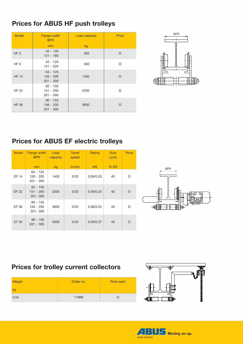
Prices for ABUS HF push trolleys
Prices for ABUS EF electric trolleys
Model Flange widthBPR
Load capacity Price
mm kg
HF 342 - 120
121 - 180300 OO
HF 642 - 120
121 - 220580 OO
HF 1464 - 125
126 - 200201 - 300
1400 OO
HF 2282 - 150
151 - 200201 - 300
2200 OO
HF 3690 - 155
156 - 200201 - 300
3600 OO
Model Flange widthBPR
Load capacity
Travel speed
Rating Duty cycle
Price
mm kg m/min kW % ED
EF 1464 - 125
126 - 200201 - 300
1400 5/20 0.06/0.25 40 OO
EF 2282 - 150
151 - 200201- 300
2200 5/20 0.06/0.25 40 OO
EF 3690 - 155
156 - 200201- 300
3600 5/20 0.06/0.25 40 OO
EF 5098 - 190
201 - 3005000 5/20 0.09/0.37 40 OO
Weight Order no. Price each
kg
3,54 11898 OO
BPR
BPR
Prices for trolley current collectors

18/19
Prices for ABUS festoon power supply system*
• The riser cable from the mainsswitch and cabling from the mainsswitch to the terminal box, includingaccessories, are not included in thescope of supply.
The voltage drop must be taken intoconsideration for the design of the festoon system.The festoon system is prefabricated,i.e. supplied with the flat cable on thecable carriers, current collector carrierand end clamp.
Standard equipment
Flat cable carrier
Transitional terminal box (flat/round cable)
End clamp
1
2
3
Flat cable4
Rail5
Rail support6
Clamping brackets8
Current collector carrier9
Trolley current collector10
Rail connector11
Mains switch12
Mounting console7
7 8 6 511
•
2
1
10
3
4
12
Lump-sum price for fixed components
Transitional terminal box, end clamp,current collector carrier, mains switch,trolley current collector
Price in EUR OO
Price for length-dependent components
Flat cable carriers, flat cable, rails, railsupports, rail connectors, mountingconsoles, clamping brackets
Price in EUR/m OO
* for track lengthsup to 30 m
max. 1,70 m
9

Moving on up.crane systems
Prices for ABUS power supply system with mobile control* * for track lengthsup to 30 m
2
1
Standard equipment
In the standard version, the pen-dant control is attached directly to the hoist by a quick plug-typeconnector.
Alternative:With this alternative, the pendantcontrol can be moved along thetrolley track independently from thehoist.The additional components requi-red include rail, flat cable, cablecarrier and control carrier with connector. The basic design is the same as for the festoon cablesystem. A mobile control carriercannot be combined with a protec-ted conductor system.
Additional rail2
The voltage drop must be taken into consideration for the design of the system.
The system is prefabricated, i.e.supplied with the flat cable on thecable carriers, current collector car-rier and end clamp.
Ple
ase
spec
ify le
ngth
Mobile control carrier1
Lump-sum price for fixed components
Fixed components as for festoon system on page 18, plus: end clamp,mobile control carrier, bolted joints,end stop
Price in EUR OO
Price for length-dependent components
Length-dependent components as for festoon system on page 18, plus:additional cable carriers, flat cable, rail supports, rail connectors for mobile control carrier
Price in EUR/m OO
20/21
3
•
49
5
7
6
1
2
8
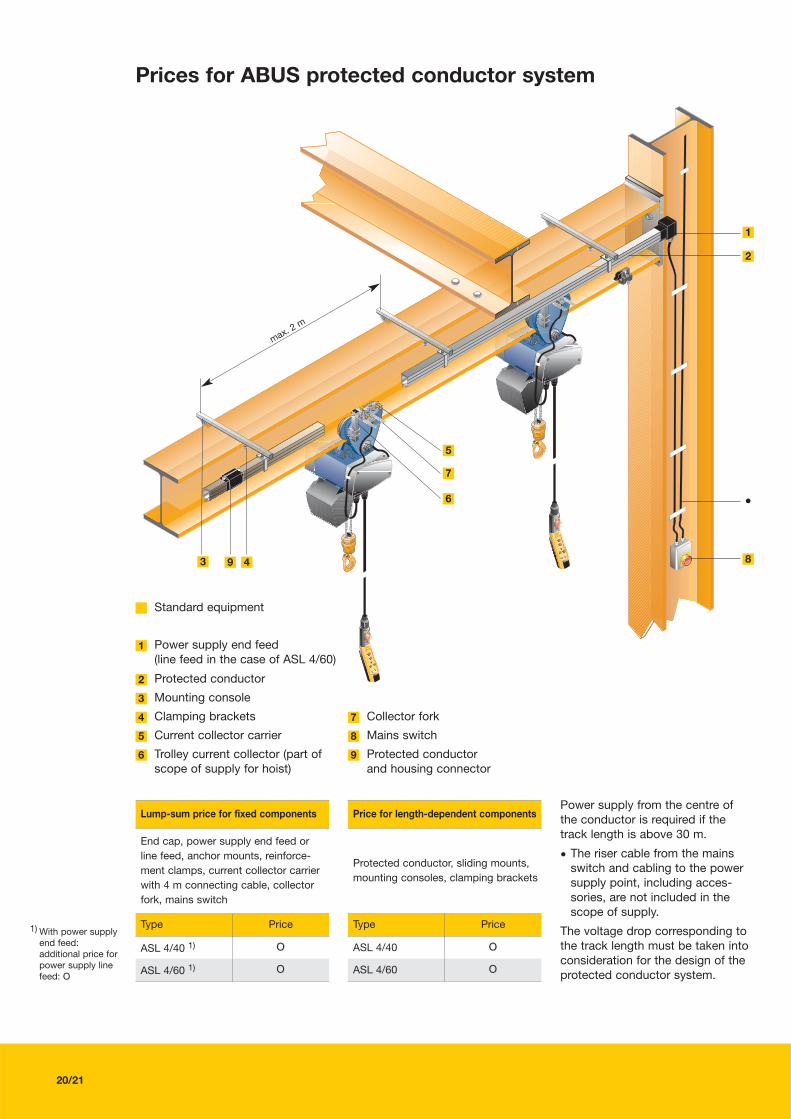
Power supply from the centre of the conductor is required if thetrack length is above 30 m.
• The riser cable from the mainsswitch and cabling to the powersupply point, including acces-sories, are not included in thescope of supply.
The voltage drop corresponding tothe track length must be taken intoconsideration for the design of theprotected conductor system.
1) With power supplyend feed: additional price forpower supply linefeed: OO
Prices for ABUS protected conductor system
Standard equipment
Mounting console
Power supply end feed(line feed in the case of ASL 4/60)
Protected conductor
1
2
3
Clamping brackets4
Current collector carrier5
Trolley current collector (part ofscope of supply for hoist)
6
Mains switch8
Protected conductor and housing connector
9
Collector fork7
Lump-sum price for fixed components
End cap, power supply end feed or line feed, anchor mounts, reinforce-ment clamps, current collector carrierwith 4 m connecting cable, collectorfork, mains switch
Type Price
ASL 4/40 1) OO
ASL 4/60 1) OO
Price for length-dependent components
Protected conductor, sliding mounts,mounting consoles, clamping brackets
Type Price
ASL 4/40 OO
ASL 4/60 OO
max. 2 m

Moving on up.crane systems
Weights and dimensions
Dimensions, ABUCompact GM2 to GM8
Dimensions, ABUCompact GM2 to GM8, stationary and with trolley
Model No. of falls Hook Trolley C C1 D1 D2 A2mm mm mm mm mm
GM2 1 012 HF 3 344 390 42 30 22GM2 1 012 HF 6 344 397 42 30 22GM2 1 012 HF 14 344 412 42 30 22GM2 1 012 EF 14 344 412 42 30 22GM2 1 025 HF 6 358 411 42 36 26GM2 1 025 HF 14 358 426 42 36 26GM2 1 025 EF 14 358 426 42 36 26GM2 2 05 HF 3 425 471 42 43 34GM2 2 05 HF 6 425 478 42 43 34GM2 2 05 HF 14 425 493 42 43 34GM2 2 05 EF 14 425 493 42 43 34GM4 1 025 HF 3 380 426 42 36 26GM4 1 025 HF 6 380 433 42 36 26GM4 1 025 HF 14 380 448 42 36 26GM4 1 025 EF 14 380 448 42 36 26GM4 2 05 HF 6 460 513 42 43 34GM4 2 05 HF 14 460 528 42 43 34GM4 2 05 EF 14 460 528 42 43 34GM8 1 05 HF 22 553 632 65 43 34GM8 1 05 EF 22 553 632 65 43 34GM8 2 1.0 HF 22 674 753 65 50 40GM8 2 1.0 HF 36 674 758 65 50 40GM8 2 1.0 EF 22 674 753 65 50 40GM8 2 1.0 EF 36 674 758 65 50 40GM8 2 1.0 EF 50 704 789 75 50 40
1) with additionalhousing
2) with EF 50 for loadcapacity 4000 kg
Weights and dimensions dependant on hook path, ABUCompact GM2 to GM8
Model No. of falls Hook path D1 H2 C2 Weightmm mm mm kg
GM 2 1 3000 42 65 357 21,8GM 2 1 4000 42 65 357 22,2GM 2 1 5000 42 65 394 22,5GM 2 1 6000 42 65 394 22,8GM 2 1 8000 42 65 394 23,5GM 2 1 10000 42 65 394 24,2GM 2 1 12000 42 65 394 24,9GM 2 1 16000 42 65 494 26,2GM 2 1 20000 42 65 494 27,6GM 2 1 24000 42 65 494 29,0GM 2 1 32000 42 65 671 31,7GM 2 2 3000 42 65 394 24,4GM 2 2 4000 42 65 394 25,1GM 2 2 5000 42 65 394 25,8GM 2 2 6000 42 65 394 26,5GM 2 2 8000 42 65 494 27,8GM 2 2 10000 42 65 494 29,2GM 2 2 12000 42 65 494 30,6GM 2 2 16000 42 65 671 33,3
Model Width Length Height Suspension bracket
Bmm
B3 mm
B4mm
Lmm
L1mm
L2mm
L3mm
Hmm
H1mm
D1mm
H2mm
Tmm
B5mm
GM2 346 175 171 313 181 132 103 194 129 42 65 21 24
GM2 1) 346 175 171 352 220 132 103 194 129 42 65 21 24
GM4 400 217 183 353 197 156 120 227 158 42 69 21 24
GM4 1) 400 217 183 390 234 156 120 227 158 42 69 21 24
GM8 542 306 236 472 254 218 198 340 235 65 105 28 28
GM8 2) 542 306 236 472 254 218 198 370 235 75 135 33 28
GM8 542 306 236 567 349 218 198 340 235 65 105 28 28
GM8 2) 542 306 236 567 349 218 198 370 235 75 135 33 28
(fold-out dimen-sioned sketches on pages 3 and 30)

22/23
Model No. of falls Hook Trolley C C1 D1 D2 A2mm mm mm mm mm
GMC 1 012 HF 3 310 356 24 30 22GMC 2 025 HF 3 355 401 24 36 26
Dimensions, ABUCompact GMC, stationary and with trolley
Dimensions, ABUCompact GMC
Weights and dimensions dependant on hook path, ABUCompact GM2 to GM8
Model No. of falls Hook path D1 H2 C2 Weightmm mm mm kg
GM 4 1 3000 42 69 417 34,5GM 4 1 4000 42 69 417 35,1GM 4 1 5000 42 69 517 35,8GM 4 1 6000 42 69 517 36,4GM 4 1 8000 42 69 517 37,7GM 4 1 10000 42 69 517 39,0GM 4 1 12000 42 69 629 40,3GM 4 1 16000 42 69 629 42,9GM 4 1 20000 42 69 629 45,5GM 4 1 24000 42 69 629 48,1GM 4 1 32000 42 69 683 53,3GM 4 2 3000 42 69 517 38,0GM 4 2 4000 42 69 517 39,3GM 4 2 5000 42 69 517 40,6GM 4 2 6000 42 69 629 41,9GM 4 2 8000 42 69 629 44,5GM 4 2 10000 42 69 629 47,1GM 4 2 12000 42 69 629 49,7GM 4 2 16000 42 69 683 54,9GM 8 1 3000 65 105 816 92,3GM 8 1) 1 3000 75 135 846 92,3GM 8 1 4000 65 105 816 94,5GM 8 1) 1 4000 75 135 846 94,5GM 8 1 5000 65 105 816 96,8GM 8 1) 1 5000 75 135 846 96,8GM 8 1 6000 65 105 816 99,1GM 8 1) 1 6000 75 135 846 99,1GM 8 1 8000 65 105 816 103,6GM 8 1) 1 8000 75 135 846 103,6GM 8 1 10000 65 105 816 108,2GM 8 1) 1 10000 75 135 846 108,2GM 8 1 12000 65 105 816 112,7GM 8 1) 1 12000 75 135 846 112,7GM 8 1 16000 65 105 816 121,8GM 8 1) 1 16000 75 135 846 121,8GM 8 1 20000 65 105 816 130,9GM 8 1) 1 20000 75 135 846 130,9GM 8 2 3000 65 105 816 101,1GM 8 1) 2 3000 75 135 846 101,1GM 8 2 4000 65 105 816 105,6GM 8 1) 2 4000 75 135 846 105,6GM 8 2 5000 65 105 816 110,2GM 8 1) 2 5000 75 135 846 110,2GM 8 2 6000 65 105 816 114,7GM 8 1) 2 6000 75 135 846 114,7GM 8 2 8000 65 105 816 123,8GM 8 1) 2 8000 75 135 846 123,8GM 8 2 10000 65 105 816 132,9GM 8 1) 2 10000 75 135 846 132,9
Weights and dimensions dependant on hook path, ABUCompact GMC
Model No. of falls Hook path D1 C2 Weightmm mm kg
GMC 1 3000 24 340 10,1GMC 1 6000 24 340 10,7GMC 1 10000 24 340 11,5GMC 1 20000 24 375 13,6GMC 2 3000 24 340 11,2GMC 2 6000 24 340 12,5GMC 2 10000 24 375 14,1
1) with EF 50 for loadcapacity 4000 kg
Model Width Length Height Suspension bracketB
mmB3 mm
B4mm
Lmm
L1mm
L2mm
L3mm
Hmm
H1mm
D1mm
H2mm
Tmm
B5mm
GMC 275 115 160 275 125 150 0 177 130 24 47 8 18
(fold-out dimen-sioned sketches on pages 3 and 30)

Moving on up.crane systems
Weights and dimensions, ABUS HF push trolleys
Dimension table, ABUS HF push trolleys
Model Flange widthBPR
Load capacity
Dimensionsmm
Minimum bend radius
Weight
mm kgAL AB DL DS DB H HK HU LB LR LH SB
(max.)N
(min.)T
(max.) mm kg
HF 342 - 7071 - 8586 - 120
300 90 85 56 75 22 135 47 28 20 165 17 2 110 20600700
10004,1
HF 3 121 - 180 300 90 85 56 75 22 135 47 28 20 165 17 2 110 20 1200 4,5
HF 642 - 7071 - 8586 - 120
580 120 100 65 85 30 153 55 32 24 205 19 2 120 20700800
11006,0
HF 6121 - 180181 - 220
580 120 100 65 85 30 153 55 32 24 205 19 2 120 2013001600
6,7
HF 1464 - 9091 - 125
1400 150 125 80 100 34 193 70 41 33 250 22 2 130 2011001500
11,0
HF 14126 - 140141 - 200
1400 150 125 80 100 34 193 70 41 33 250 22 2 130 2017002100
11,9
HF 14 201 - 300 1400 150 125 80 100 34 193 70 41 33 250 22 2 130 20 2250 12,9
HF 2282 - 125
126 - 1402200 180 160 112 140 50 236 90 41 41 320 28 2 160 21,5
17002100
23,8
HF 22 141 - 200 2200 180 160 112 140 50 236 90 41 41 320 28 2 160 21,5 2200 24,8
HF 22 201 - 300 2200 180 160 112 140 50 236 90 41 41 320 28 2 160 21.5 2300 26,9
HF 3690 - 125
126 - 1403600 180 170 112 140 60 253 90 41 49 320 33 2 160 21,5
17002100
28,6
HF 36 141 - 200 3600 180 170 112 140 60 253 90 41 49 320 33 2 160 21,5 2200 29,9
HF 36 201 - 300 3600 180 170 112 140 60 253 90 41 49 320 33 2 160 21,5 2300 32,2

Moving on up.crane systems
24/25
Dimension table, ABUS EF push trolleys
Counterweight only for EF 14 with F = 64 to 200 mm and EF 22 with F = 82 to 150 mm
ABUS EF 14-36 electric trolleys ABUS EF 50 electric trolleys
Model Flange widthBPR
Load capacity
Travel speed Rating Duty cycle
Dimensionsmm
Dimensionsmm
Minimum bend radius
Weight
mm kg m/min kW % EDAL AB DL DS DK DB H HK HV HU LB LR LH LV SB
(max.)LE LW LC MO OK N
(min.)T
(max.) mm kg
EF 1464 - 9091 -125
1400 5/20 0.06/0.25 40 150 125 80 100 115 34 193 70 31.5 41 33 265 22 175 2 34 373 339 124 - 130 2011001500
31,2
EF 14126 -140141 -200
1400 5/20 0.06/0.25 40 150 125 80 100 115 34 193 70 31.5 41 33 265 22 175 2 34 373 339 124 - 130 2017002100
32,2
EF 14 201 -300 1400 5/20 0.06/0.25 40 150 125 80 100 115 34 193 70 31.5 41 33 265 22 0 2 34 373 339 124 - 130 20 2250 32,9
EF 2282 -125
126 -1402200 5/20 0.06/0.25 40 180 160 112 140 155 50 236 90 47 41 41 335 28 175 2 39 377 338 124 - 160 21,5
17002100
32,4
EF 22 141 -200 2200 5/20 0.06/0.25 40 180 160 112 140 155 50 236 90 47 41 41 335 28 0 2 39 377 338 124 - 160 21,5 2200 33,4
EF 22 201 -300 2200 5/20 0.06/0.25 40 180 160 112 140 155 50 236 90 47 41 41 335 28 0 2 39 377 338 124 - 160 21.5 2300 35,5
EF 3690 -125
126 -1403600 5/20 0.06/0.25 40 180 170 112 140 155 60 253 90 47 41 49 335 33 0 2 44 383 339 124 - 160 21,5
17002100
36,5
EF 36 141 -200 3600 5/20 0.06/0.25 40 180 170 112 140 155 60 253 90 47 41 49 335 33 0 2 44 383 339 124 - 160 21,5 2200 37,7
EF 36 201 -300 3600 5/20 0.06/0.25 40 180 170 112 140 155 60 253 90 47 41 49 335 33 0 2 44 383 339 124 - 160 21,5 2300 40,0
EF 5090 -125
126 -2005000 5/20 0.09/0.37 40 220 190 140 180 183 70 348 115 30 90 50 403 54 0 2 54 477 423 158 100 190 40
18002000
71,1
EF 50 201 -300 5000 5/20 0.09/0.37 40 220 190 140 180 183 70 348 115 30 90 50 403 54 0 2 54 477 423 158 100 190 40 2200 76,1
Weights and dimensions, ABUS EF electric trolleys

Company:
Name:
Address:
Phone:
Fax:
26/27
F��
����
The first step towards your ABUCompact
Just copy the form, fill in your details
and fax it to us. We will send you an
initial quotation as soon as possible.
Quantity: ___________ Load capacity: _____________ kg Hook path: _____________ m
Quantity: ___________ Load capacity: _____________ kg Hook path: _____________ m
What lifting speeds do you need?
Details of the hoist you need:
high lifting speeds because of long hook path and frequent use
precise lifting and lowering more important than speed
please provide advice
What operating voltage is available?
3 x 400 V / 50 Hz
______ V / ______ Hz
Is a power supply system required?
no
yes, I am interested in
Do you need to move the load along a girder?
no (stationary use)
If so, is a trolley track girder available?
yes
yes, with push trolley (push-pull operation)
yes, with electric trolley (electric operation)
a festoon system (max. travel 30 m)
a protected conductor (for longer travel or more thanone hoist on one girder)
please provide advice
length: ____________________________ mm
height: ____________________________ mm
flange width BPR: ________________ mm
type of profile: ________________________
no
If you prefer a festoon system, do you need a mobile control carrier?
please provide advice
no
yes

Moving on up.crane systems
Notes
28/29/30
Notes

Notes

with EF electric trolleywith HF push trolley
Moving on up.crane systems
Dimensioned sketches of chain hoists
ABUCompact GM8
stationary with additional housing

Dimensioned sketchesABUCompact GM8
Please fold page out

____
_/__
__/8
.04
Moving on up.crane systems
Australia – Eilbeck Cranes6 Moorlands Road · Ingleburn NSW 2565 · Ph. 61 (0)2 9829 3700 · fax 61 (0)2 9829 3500 · e-mail: [email protected] Jackson Street · Bassendean WA 6054 · Ph. 61 (0)8 9279 4800 · fax 61 (0)8 9378 3689 · e-mail: [email protected] Sudbury Street · Darra QLD 4076 · Ph. 61 (0)7 3271 3790 · fax 61 (0)7 3271 3791 · e-mail: [email protected]
Australia – Modular Cranes33 Colbert Road · Cambellfield VIC 3061 · Ph. 61 (0)3 9357 9877 · fax 61 (0)3 9357 9822 · e-mail: [email protected]
New Zealand – Baker Cranes10 Aerovista Place · Wiri, Auckland · Ph. 64 (0)9 277 0736 · fax 64 (0)9 277 0736 · e-mail: [email protected]
Vietnam – AVC206 Road · Lac Hong Commune · Van Lam District · Hung Yen Province · VietnamPh. 84 321 980 410 · fax 84 321 980 411 · e-mail: [email protected]