ELCT 201: Digital Logic Designeee.guc.edu.eg/Courses/Electronics/ELCT201 Digital Logic...BASIC LOGIC...
54
ELCT201: DIGITAL LOGIC DESIGN Prof. Dr. Eng. Tallal El-Shabrawy, [email protected] Dr. Eng. Wassim Alexan, [email protected] Lecture 1 حرم م1441 هــSpring 2020 Following the slides of Dr. Ahmed H. Madian
Transcript of ELCT 201: Digital Logic Designeee.guc.edu.eg/Courses/Electronics/ELCT201 Digital Logic...BASIC LOGIC...

ELCT201: DIGITAL LOGIC DESIGN Prof. Dr. Eng. Tallal El-Shabrawy, [email protected]
Dr. Eng. Wassim Alexan, [email protected]
Lecture 1
هــ 1441محرم
Spring 2020
Following the slides of Dr. Ahmed H. Madian

2


4

5

6
Most of electronic devices consist of two integrated systems
Software Hardware
Programs that control hardware to execute user wishes
To learn how to design this you need to study
Programming
Circuits that execute the program commands
To learn more about how to design this you need to study
Digital Logic Design
THE IMPORTANCE OF DIGITAL LOGIC

THE IMPORTANCE OF DIGITAL LOGIC
Floyd 11th edition
7

COURSE OBJECTIVES
Understand the theory of operation for most of digital electronic devices
Analyze how a digital computer performs complex operations, based on simply manipulating bits (0s and 1s)
Design digital logic systems
8
TEXT AND REFERENCE BOOKS
Textbook:
M. Morris Mano, “Digital Design”, 3rd Edition, Prentice-Hall, 2002, ISBN 0-13-062121-8.
References:
S. Brown , Z. Vranesic, “Fundamentals Of Digital Logic With VHDL Design”, ISBN 0-07-012591-0.
G. Langholz, A. Kandel, & J. L Mott, “Foundations of digital logic design”, ISBN 981-02-3110-5.
D. J. Comer, “Digital Logic and State Machine Design”, ISBN 978-0195107234.
Thomas L. Floyd, “Digital Fundamentals”, ISBN 978-0131946095
9

ELCT 201: DIGITAL LOGIC
Instructors Prof. Tallal El-Shabrawy
Dr. Wassim Alexan
Teaching Assistants Eng. Minar El-Aasser
Eng. Sara Farrag
Eng. Yasmin Massoud
Eng. Heba El-Hosary
Eng. Hadeer Ramadan
Eng. Menna Saleh
10
Grading
Assignments 5%
Project 5%
Quizzes 20%
Midterm Exam 25%
Final Exam 45%

COURSE OUTLINE
1. Introduction
2. Gate-Level Minimization
3. Combinational Logic
4. Synchronous Sequential Logic
5. Registers and Counters
6. Memories and Programmable Logic
11

FLASHBACK ON DIGITAL LOGIC DESIGN HISTORY
12

HOW DID IT ALL START?
1850: George Boole invents Boolean algebra
13

HOW DID IT ALL START?
14
1946: ENIAC, the first electronic computer is developed
18,000 vacuum tubes
5,000 operations per second
1,000 square feet
It really cost a lot of power to
turn on the switch!
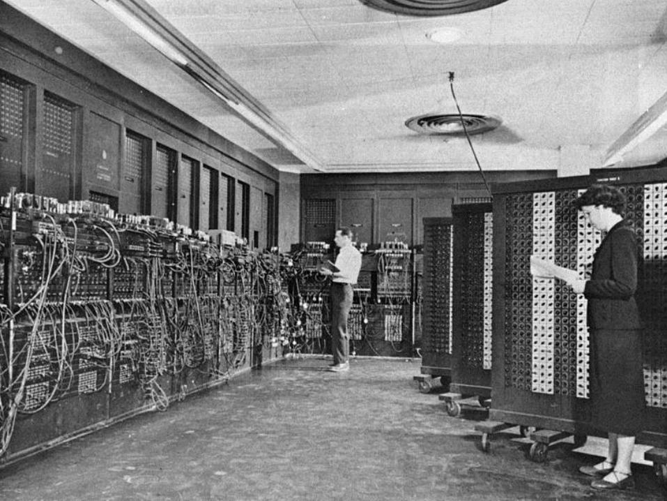
Dr. Haitham Omran, Dr. Wassim Alexan 15

AND IT WENT ON…
1947: Shockley, Brattain, and Bardeen invent the transistor
Replaces vacuum tubes
Enables integration of multiple devices into one package
1956: They received the Nobel
Prize in Physics
16

AND IT WENT ON…
1955: AT&T Bell Labs announced the first fully transistorized computer, TRADIC
1958: The first 2D Integrated Circuit (Kilby received the Nobel prize in 2000)
•Transistors, resistors and capacitors on the same piece of semiconductor
•Interconnects between components is not integrated
•Low connectivity between components
17
AND IT WENT ON…
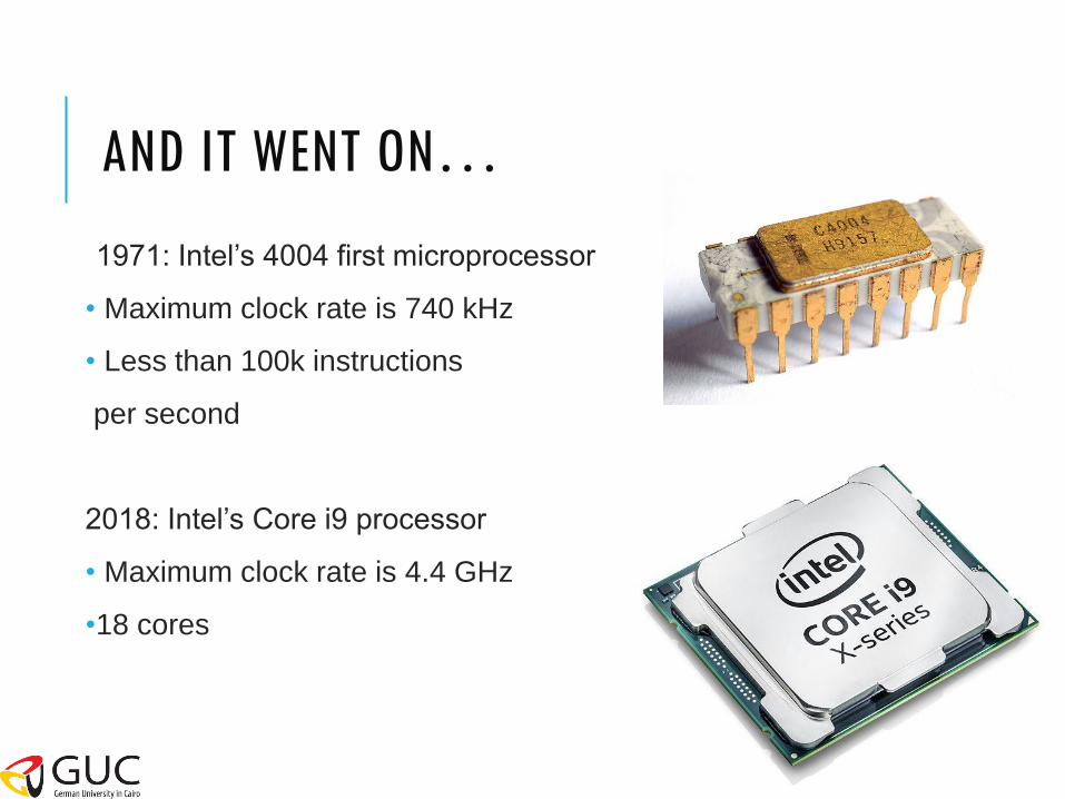
1971: Intel’s 4004 first microprocessor
• Maximum clock rate is 740 kHz
• Less than 100k instructions
per second
2018: Intel’s Core i9 processor
• Maximum clock rate is 4.4 GHz
•18 cores
18

Conventional computer design
CPUs, busses, peripherals
Networking and communications
Phones, modems, routers
Embedded products
Cars
Toys
Appliances
Entertainment devices: MP3 players, gaming consoles (PlayStation, Xbox, etc…)
APPLICATIONS OF DIGITAL LOGIC DESIGN
19

20
BUT WHAT IS THE MEANING OF DIGITAL LOGIC DESIGN?

WHAT IS DIGITAL?
• Digital describes any system based on discontinuous data or events
• Computers are digital machines because at their most basic level they can
distinguish between just two values, 0s and 1s, or off and on
• There is no simple way to represent all the values in between, such as 0.25
• All data that a computer processes must be encoded digitally, as a sequence
of 0s and 1s
21

ANALOG VS. DIGITAL
22
• An analog signal is any variable signal continuous in both time and amplitude
(e.g. sound)
Example:
A typical analog device is a clock in which the hands move continuously around the face. Such a clock is capable of indicating every possible time of day. In contrast, a digital watch is capable of representing only a finite number of times (e.g. every tenth of a second)

WHY DIGITAL?
Digital systems are easier to design and implement than analog systems.
23

WHAT IS LOGIC DESIGN?
Given a specification of a problem, an engineer needs to come up with a way of solving it, choosing appropriately from a collection of available components, while meeting some criteria for size, cost or power.
24

25
Digital Logic Gates!
These are the basic units used to build any digital circuit
WHAT ARE THE BASIC UNITS USED TO BUILD THESE DIGITAL CIRCUITS?
26
DIGITAL LOGIC LEVELS
26
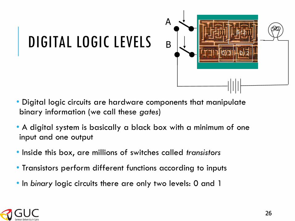
Digital System
A
B
• Digital logic circuits are hardware components that manipulate binary information (we call these gates)
• A digital system is basically a black box with a minimum of one input and one output
• Inside this box, are millions of switches called transistors
• Transistors perform different functions according to inputs
• In binary logic circuits there are only two levels: 0 and 1

27
DIGITAL LOGIC LEVELS
27
• What is the physical meaning of logic 0 and logic 1?
• How can we recognize them?

DIGITAL LOGIC LEVELS
28
Voltage
Time
Logic – 1 range
Transition (occurs
between the two limits)
Intermediate
region,
crossed only
during state
transition Logic – 0 range
5
0.8
0
2
• Electrical signals (voltages or currents) that exist in a digital system are in either of two recognizable values (logic 1 or logic 0)

29
BOOLEAN ALGEBRA
29
• What is the difference between Boolean algebra and arithmetic algebra?
• The first difference is that in Boolean algebra we have only the (+) and () operators, but we do not have subtraction (-) or division (/) like in mathematics
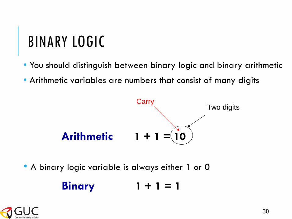
BINARY LOGIC
• You should distinguish between binary logic and binary arithmetic
• Arithmetic variables are numbers that consist of many digits
• A binary logic variable is always either 1 or 0
Binary 1 + 1 = 1
30
Arithmetic 1 + 1 = 10
Two digits Carry
DIGITAL LOGIC GATES
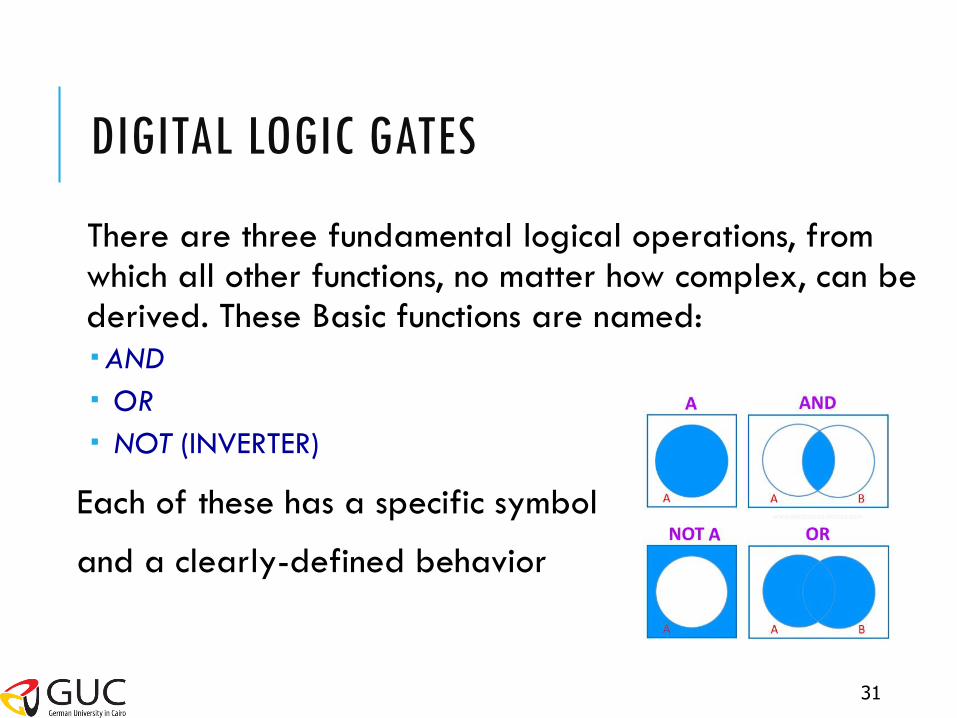
There are three fundamental logical operations, from which all other functions, no matter how complex, can be derived. These Basic functions are named:
AND
OR
NOT (INVERTER)
Each of these has a specific symbol
and a clearly-defined behavior
31

BASIC DIGITAL LOGIC GATES (CONT.)
AND Gate
Represented by any of the following notations:
X AND Y
X . Y
X Y
Function definition:
Z=1 only if X=Y=1
0 otherwise
X
YZ
32
Symbol diagram
AND
AND X Y
Switch representation
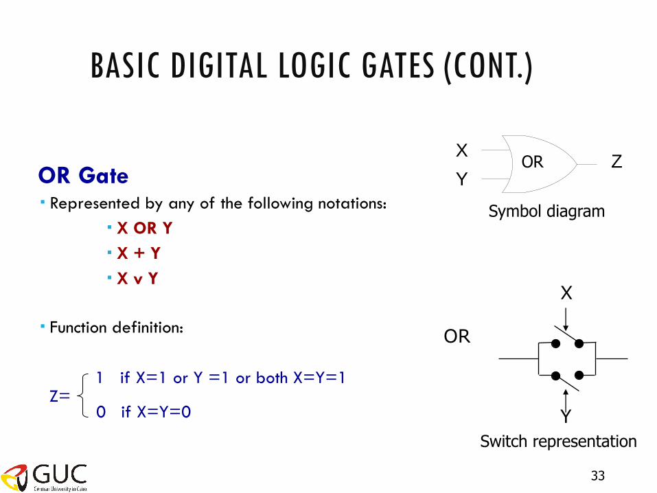
BASIC DIGITAL LOGIC GATES (CONT.)
OR Gate Represented by any of the following notations:
X OR Y
X + Y
X v Y
Function definition:
1 if X=1 or Y =1 or both X=Y=1
0 if X=Y=0
X
YZ
33
Symbol diagram
OR
OR
X
Y
Switch representation
Z=
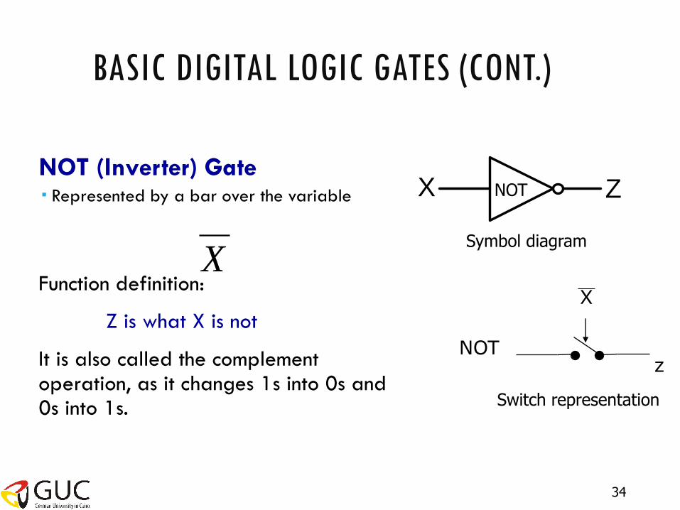
BASIC DIGITAL LOGIC GATES (CONT.)
NOT (Inverter) Gate Represented by a bar over the variable
Function definition:
Z is what X is not
It is also called the complement operation, as it changes 1s into 0s and 0s into 1s.
X Z
X
34
Symbol diagram
NOT
NOT
X
z
Switch representation

LOGIC GATES TIMING DIAGRAM
35
• Timing diagrams illustrate the response of any gate to all possible input
signal combinations
• The horizontal axis of the timing diagram represents time and the vertical
axis represents the signal as it changes between the two possible voltage
levels 1 or 0

DIGITAL LOGIC GATES
Gates can have more than 2 inputs
Other Types of logic gates
36
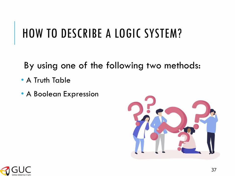
HOW TO DESCRIBE A LOGIC SYSTEM?
37
By using one of the following two methods:
• A Truth Table
• A Boolean Expression

Z Y X
0
0
0
1
0
1
0
1
0
0
1
1
X
YZ
38
A Truth Table is a table of combinations of the binary variables showing the relationship between the different values that the input variables take and the result of the operation (output). The number of rows in the Truth Table is , where n = number of input variables in the function. The binary combinations are obtained from the binary number by counting from 0 to
n2
12n
Truth table of an AND gate
Example: AND gate with 2 inputs
n=2
The truth table has 22 rows = 4
The binary combinations are from 0 to (22-1=(3)) {00,01,10,11}
All input
combinations output
TRUTH TABLES

BOOLEAN EXPRESSIONS
We can use these basic operations to form more complex expressions:
f(x,y,z) = (x + y’)z + x’
Some terminology and notation: f is the name of the function
(x,y,z) are the input variables, each representing 1 or 0. Listing the inputs is optional, but sometimes helpful
A literal is any occurrence of an input variable or its complement. The function above has four literals: x, y’, z, and x’
Precedencies are important, but not too difficult NOT has the highest precedence, followed by AND, and then OR
Fully parenthesized, the function above would be kind of messy:
f(x,y,z) = (((x +(y’))z) + x’)
39
39

40
HOW TO GET THE BOOLEAN EXPRESSION FROM THE TRUTH TABLE?

BOOLEAN EXPRESSIONS FROM TRUTH TABLES
41
Each 1 in the output of a truth table specifies one term in the corresponding Boolean expression The expression can be read off by inspection…
A B C F
0 0 0 0
0 0 1 0
0 1 0 1
0 1 1 0
1 0 0 0
1 0 1 0
1 1 0 0
1 1 1 1
F is true when: A is false AND B is true AND C is false OR A is true AND B is true AND C is true
F = A’BC’ + ABC
Sum-of-Products-Algorithm

ANOTHER EXAMPLE
42
F = A’B’C +
A’BC’ +
AB’C’ +
ABC
F = ?
A B C F
0 0 0 0
0 0 1 1
0 1 0 1
0 1 1 0
1 0 0 1
1 0 1 0
1 1 0 0
1 1 1 1
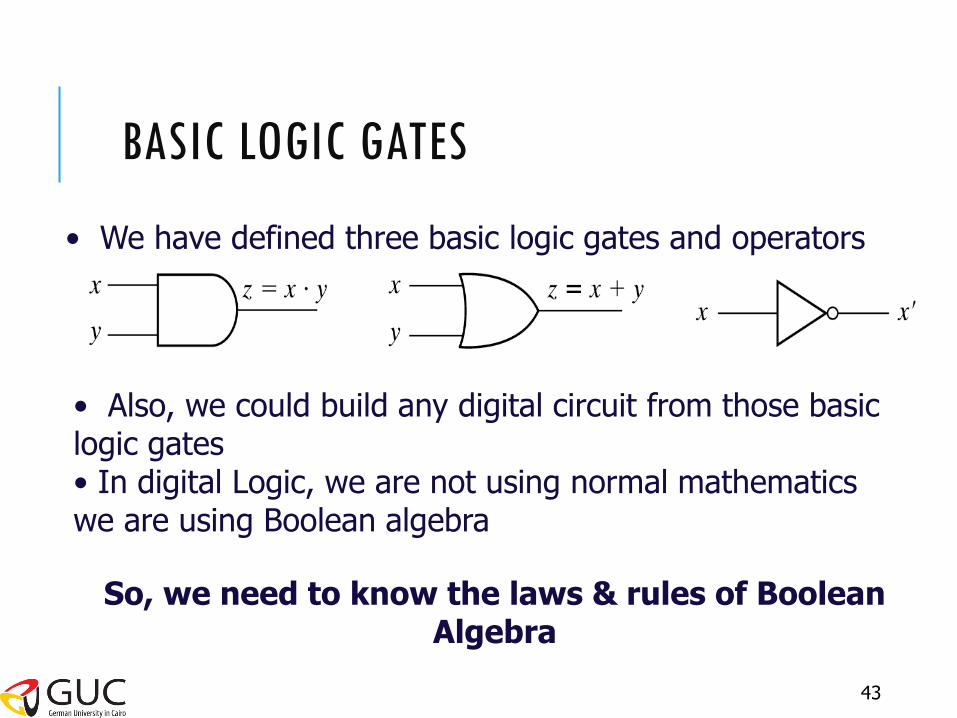
BASIC LOGIC GATES
• We have defined three basic logic gates and operators
• Also, we could build any digital circuit from those basic logic gates • In digital Logic, we are not using normal mathematics we are using Boolean algebra
So, we need to know the laws & rules of Boolean Algebra
43

LAWS & RULES OF BOOLEAN ALGEBRA
The basic laws of Boolean algebra The commutative law
The associative law The distributive law
44

COMMUTATIVE LAW
45
The commutative law of addition for two variables is
A+B = B+A
The commutative law of multiplication for two variables is AB = BA
A
B A+B
B
A B+A
A
B AB
B
A BA
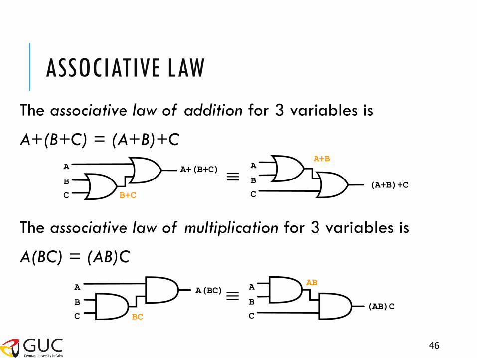
ASSOCIATIVE LAW
A
B
A+(B+C)
C
A
B (A+B)+C
C
A
B
A(BC)
C
A
B (AB)C
C
B+C
A+B
BC
AB
46
The associative law of addition for 3 variables is
A+(B+C) = (A+B)+C
The associative law of multiplication for 3 variables is
A(BC) = (AB)C

DISTRIBUTIVE LAW
47
B
C
A
B+C A
B
C
A X
AB
AC
X=A(B+C) X=AB+AC
X=A+(B.C)
B
C
A X
A
B
C
A
X
X=(A+B)(A+C)
BC A+B
A+C
The distributive law for multiplication is
A(B+C) = AB + AC
The distributive law for addition is
A+(B.C) = (A+B)(A+C)
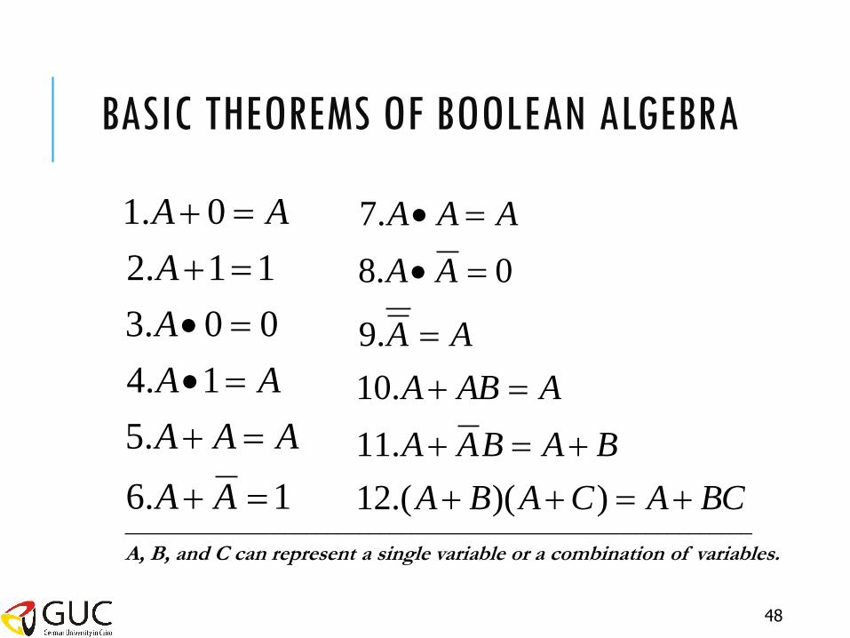
BASIC THEOREMS OF BOOLEAN ALGEBRA
1.6
.5
1.4
00.3
11.2
0.1
AA
AAA
AA
A
A
AA
BCACABA
BABAA
AABA
AA
AA
AAA
))(.(12
.11
.10
.9
0.8
.7
___________________________________________________________
A, B, and C can represent a single variable or a combination of variables.
48
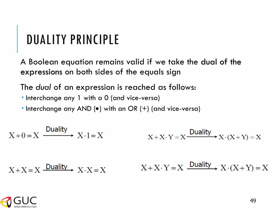
DUALITY PRINCIPLE
49
A Boolean equation remains valid if we take the dual of the expressions on both sides of the equals sign
The dual of an expression is reached as follows:
Interchange any 1 with a 0 (and vice-versa)
Interchange any AND () with an OR (+) (and vice-versa)

DEMORGAN’S LAW
BABA
BABA
50
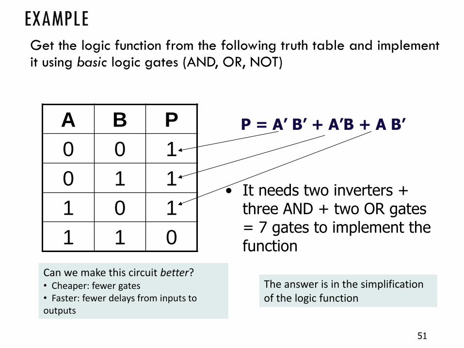
EXAMPLE Get the logic function from the following truth table and implement it using basic logic gates (AND, OR, NOT)
A B P
0 0 1
0 1 1
1 0 1
1 1 0
P = A’ B’ + A’B + A B’
• It needs two inverters + three AND + two OR gates = 7 gates to implement the function
Can we make this circuit better? • Cheaper: fewer gates • Faster: fewer delays from inputs to outputs
The answer is in the simplification of the logic function
51

SIMPLIFICATION OF THE LOGIC FUNCTION
P=A’B’ + A’B + AB’
= A’ * (B’ + B) + A * B’ (Distributivity)
= A’ * (B + B’) + A * B’ (Commutativity)
= A’ * 1 + A * B’ (x + x’ = 1)
= A’ + (A * B’) (x +x’y)=(x+x’)(x+y)(Distributivity)
= (A’ + B’) (De Morgan’s)
= (A B)’ 1 GATE (NAND) ONLY
Simplification rules allow us here to optimize the design and use a single gate!
52
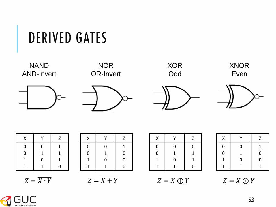
Z Y X
1
0
0
1
0
1
0
1
0
0
1
1
Z Y X
0
1
1
0
0
1
0
1
0
0
1
1
Z Y X
1
1
1
0
0
1
0
1
0
0
1
1
Z Y X
1
0
0
0
0
1
0
1
0
0
1
1
NAND
AND-Invert
NOR
OR-Invert
XOR
Odd
XNOR
Even
53
DERIVED GATES

FINAL NOTE
Check the EEE website http://eee.guc.edu.eg for the course materials as well as any announcements
54
![Gates and Logic: From Transistors to Logic Gates and Logic ......Gates and Logic: From Transistors to Logic Gates and Logic Circuits [Weatherspoon, Bala, Bracy, and Sirer] Prof. Hakim](https://static.fdocuments.us/doc/165x107/5fa95cb6eb1af8231472f381/gates-and-logic-from-transistors-to-logic-gates-and-logic-gates-and-logic.jpg)